

Page 1
Data sheet
Actuator for three point control
AMV 435
Description
AMV 435 actuator is used with two and three-way
valves type VRB, VRG, VF and VL up to DN 80
diameter and for AHQM DN 40-100. It is also
used with pressure independent balancing and
control valve type AB-QM from DN 40 to DN 100.
Ordering Actuator
Typ e Supply voltage Code No.
AMV 435
Accessories - Stem heater
Typ e DN
Stem heater 15- 80 24 V 065Z0315
24 VAC /DC 082H0162
230 VAC 082H0163
Power
supply
Code No.
The advanced design incorporates load related
‘switch-o’ to ensure that actuators and valves
are not exposed to overload.
Combinations with other valves could be seen
under Accessories.
Main data:
• Nominal voltage:
- 24 VAC/DC, 50 Hz/60 Hz
- 230 VAC, 50 Hz/60 Hz
• Control input signal:
3 point
• Force: 400 N
• Stroke: 20 mm
• Speed (selectable):
- 7.5 s/mm
- 15 s/mm
• Max. medium temperature: 130 °C
• LED signalling
• End-position signals
• Manual operation
Accessories - Adapter
Valves DN
For old VRB, VRG,
VF, VL valves
For AB-QM 1st gen. 40 - 100 -
max Δp
(bar)
15 9
20 4
25 2
32 1
40 0.8
50 0.5
Code No.
065Z0313
Technical data
DEN-SMT/SI
Power supply V 24 AC/DC, 230 AC; +10 to –15%
Power consumption VA 3 (24 V); 7,6 (230 V)
Frequency Hz 50 or 60 (for VAC power supply)
Control input 3 point
Close of force N 400
Max. stroke mm 20
Speed s/mm 7,5 or 15
Max. medium temperature
Ambient temperature 0 … 55
Storage and transport temperature –40 … +70
Protection class II
Degree of protection IP 54
Weight kg 0,45
- marking in accordance with
standards
VD.LE.N5.02 © Danfoss 11/2014
o
C
Low Voltage Directive (LVD) 2006/95/EC: EN 60730-1, EN 60730-2-14
EMC Directive 2004/108/EC: EN 61000-6-2, EN 61000-6-3
130
1
Page 2
Data sheet Actuator for three point control AMV 435
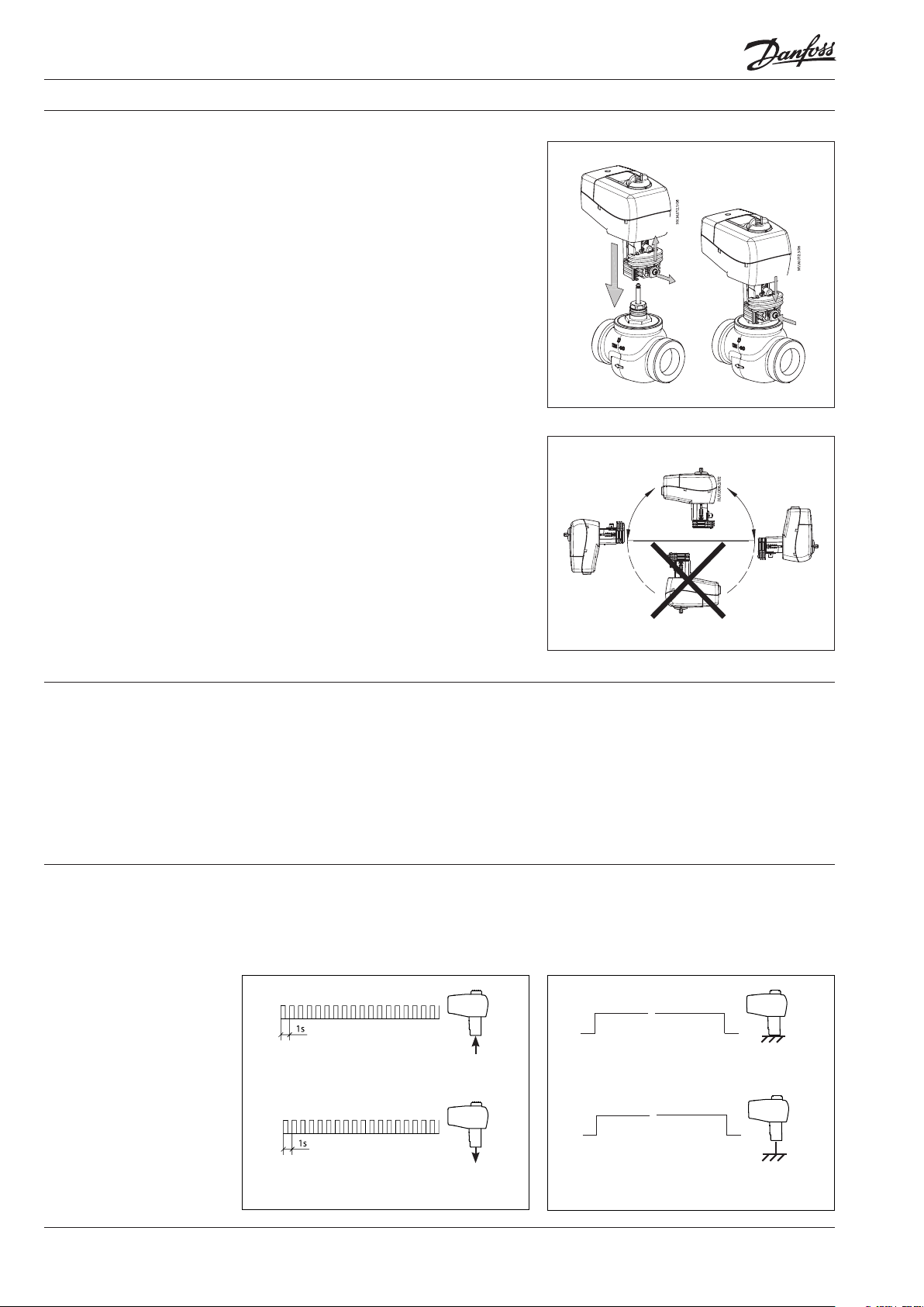
Installation Mechanical
No tool is required to mount actuator on the
valve. Installation of the valve with the actuator
is allowed in horizontal position or upwards.
Installation downwards is not allowed.
The actuator must not be installed in an
explosive atmosphere, at ambient temperature
lower than 0 °C or at ambient temperature higher
than 55 °C. It must not be subject to steam jets,
water jets or dripping liquid as well.
Note:
The actuator may be rotated up to 360° with respect
to the valve stem by loosening the retaining xture.
Once the actuator is placed, retighten the xture.
Electrical
Electrical connections can be accessed by
removing the actuator cover. Two cable gland
entries without thread (Ø16 and combined Ø16/
Ø20) are prepared for cable glands. From factory
one entry is provided by rubber cable gland and
the other entry is prepared for opening.
Note:
Cable and cable gland used must not compromise
the actuator’s IP rating, and must ensure the
connectors are fully strain relieved.
Rubber cable gland delivered from factory does not
compromise IP rating but it does not provide fully
strain relieve according to LVD directive.
Please observe local rules and regulations as well.
③
①
②
⑤
④
Commissioning
LED signalling/
Actuator operating mode
Complete the mechanical and electrical
installation and perform the necessary checks
and tests:
• Apply power
• Apply the appropriate control signal and
check that the valve stem direction is correct
for the application.
The unit is now fully commissioned.
LED function indicator
The bi-colour (green/red) LED function indicator
is located on the actuator cover. It indicates the
operating modes.
Flashing red LED:
moving to retracted position
≈
Constant red LED:
retracted position reached
≈
Flashing green LED:
moving to extrac ted position
2
VD.LE.N5.02 © Danfoss 11/2014
Constant green LED:
extracted position reached
DEN-SMT/SI
Page 3

Data sheet Actuator for three point control AMV 435
Manual override Manual override is done by means of control
knob on actuator housing:
• Disconnect control signal
• Adjust valve position using the control knob
(observe the rotation direction)
After manual override is not needed:
• Restore control signal
Wiring
Do not touch anything on the PCB!
Do not remove the cover before the
power supply is fully switched o.
Max. power allowed on ports
4 and 5 is 7 VA.
down
power
supply
down
Terminals 1, 3:
Control voltage input from the controller.
Power supply 24 VAC/DC, 230 VAC (dependent
on type)
Note:
AB-QM valve closes if moved to extracted position
(terminal 1) and opens if moved to retracted
position (terminal 3).
up
Terminals 4, 5:
Output used for position indication or
monitoring
N
Neutral/Common (0 V)
Wiring length
0-50 m 0.75 mm
> 50 m 1.5 mm
up
Recommended crosssectional area of the wiring
2
2
Disposal The actuator must be dismantled and the
elements sorted into various material groups
before disposal.
DEN-SMT/SI
VD.LE.N5.02 © Danfoss 11/2014
3
Page 4

Data sheet Actuator for three point control AMV 435
Dimensions
147
82,5
Actuator - valve combinations
159, 5
min. 180
AMV 435 + AMV 435 + AMV 435 + AMV 435 + AMV 435 + AMV 435 +
VRB 2, VRG 2 VRB 3, VRG 3 VF 2, VL 2 VF 3, VL 3 AB-QM (DN 40-100) AHQM (DN 40-100)
4
VD.LE.N5.02
Produce d by Danfoss A/S © 11/2014
 Loading...