

Tech Note
Electrical Connection – Actuator substitution
AMV(E) 410,413,613,633 AME 655GA / 659 SD
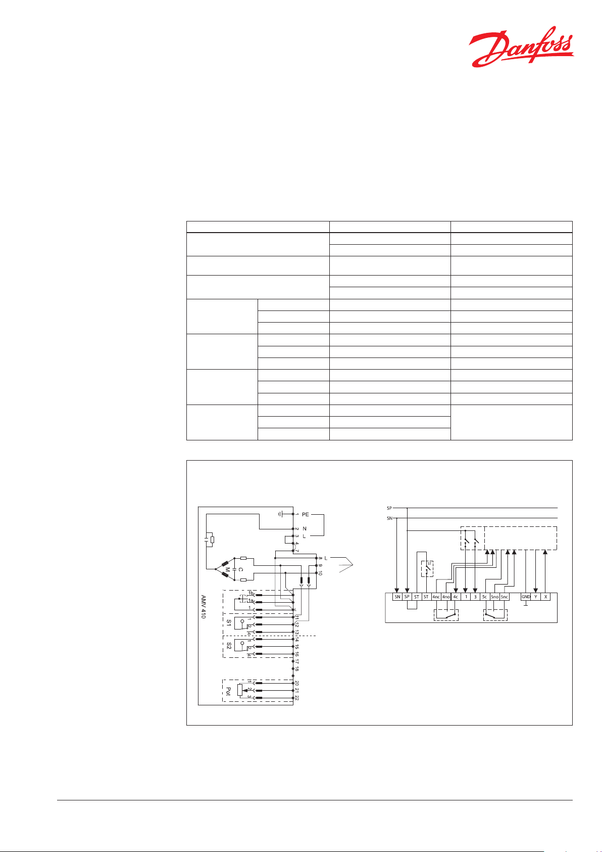
AMV 410 to
AME 655 GA / 659 SD
Description AMV 410 AME 655 GA / 659 SD
Power supply
Protective conductor PE
Safety device STV / ASB / SDB
L SP
N SN
No longer necessary (protective
insulated housing)
4 ST
7 ST
L 8 No longer necessary
Setpoint
Open 9 3
Close 10 1
Limit switch
(open)
Limit switch
(clos ed)
Combined 11 5c
NC 12 5nc
NO 13 5no
Combined 14 4c
NC 15 4nc
NO 16 5nc
Open 20
Potentiometer
Stroke 21
Use feedback signal instead
closed 22
AMV 410
AME 655 GA / 659 SD
DEN-SMT/SI
VN .I R.A1. 02 © Danf oss 01/2016
Power supply
230 V AC
with connection of STB/SDW
remove jumper
open
close
open
close
open
stroke
close
to from
controller
1
Tech Note Electrical Connection – Actuator substitution
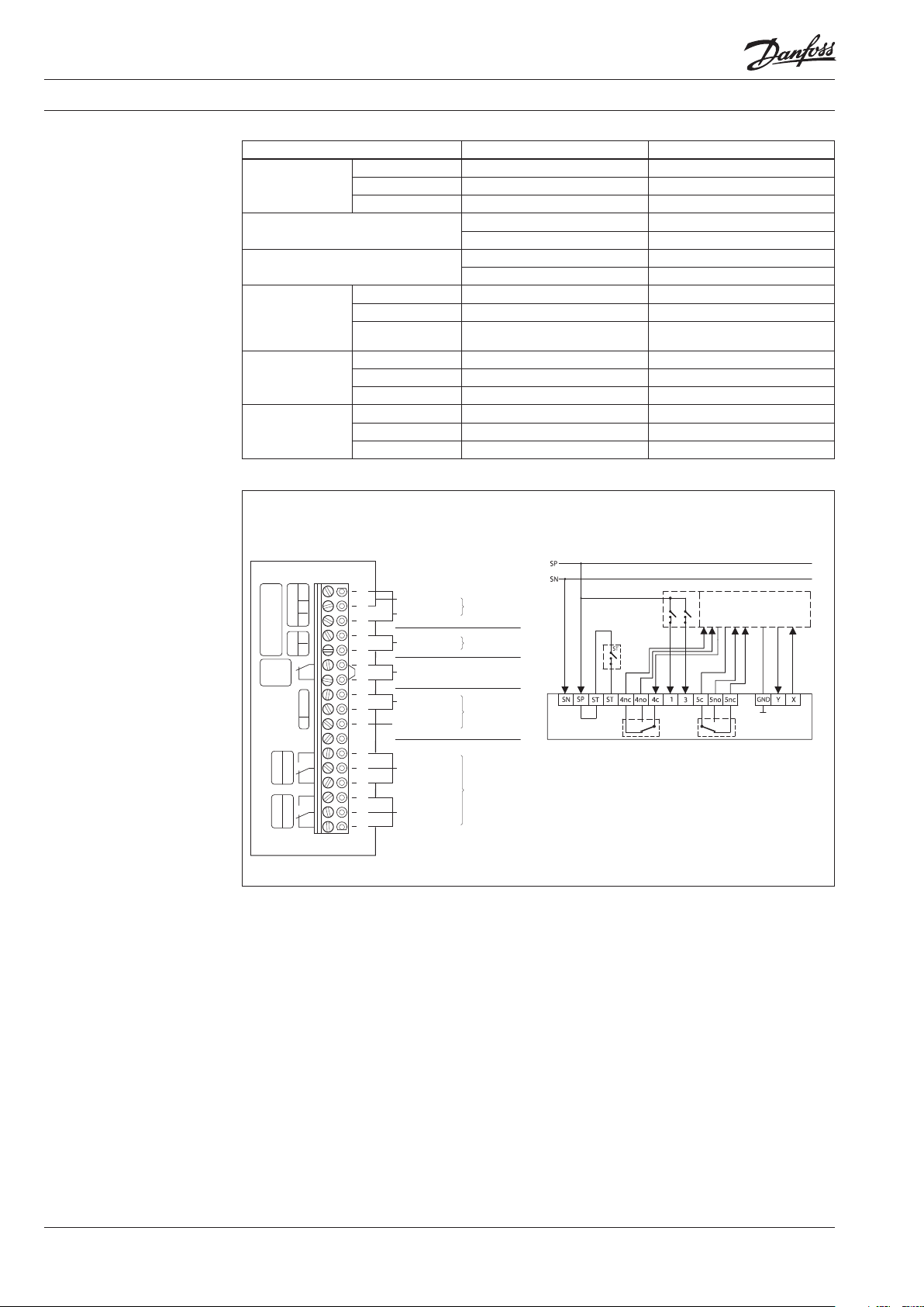
AME 410/413 to
AME 655 GA/659 SD
Description AME 410 / 413 AME 655 GA / 659 SD
Ground 1 GND
Setpoint
Current-Signal 2 Y (DIP 8 for U/I Selection)
Voltage-Signal 3
Feedback signal
Safety Device STW/STB/SDB
4 GND
5 X (DIP 9 for U/I Selection)
6 ST
7 ST
L 8 SP
Power supply
Limit switch
(clos ed)
Limit switch
(clos ed)
N 9 SN
PE 10
No longer necessary
(protective insulated housing)
NO 11 4no
Combined 12 4c
NC 13 4nc
NO 14 5no
Combined 15 5c
NC 16 5nc
AM E 410, 413 AME 655 GA / 659 SD
0(2) - 10V oder
0(4) - 20m A
AUSG . EING.
STB
STW
SD B
GND.
+U –I
PE 24V AC
0(4) - 20 mA DC
0(2) - 10 V DC
0(4) - 20 mA DC
0(2) - 10 V DC
At connection of STB, STW, SDB
remove jumper
24 V AC
PE
Input
Output stroke
Power supply
ZU AUF
GRENZK. GRENZK.
Valve
“CLOSE”
extend stem
Valve
“OPEN”
stem raised
Limit contacts
maks. 24 V
2
VN .I R.A1. 02 © Danf oss 01/2016
DEN-SMT/SI

Valve stroke
0/4 - 20 mA
External control
pot. freie Kontakte
Limit contacts for position “CLOSE”
Limit contacts for position “OPEN”
Safety pressure limiter
Safety temperature limiter
Power supply
L/N/PE ~ 230
Tech Note Electrical Connection – Actuator substitution
AMV 610/613/633 to
AME 655 GA/659 SD
Description AMV 610 / 613 / 633 AME 655 GA / 659 SD
-mA 20 GND
Feedback signal
+mA 19 X (Dip 9 for U/I Selection)
Isolation 18 No longer necessary
No longer necessary
(protective insulated housing)
Setpoint
PE 17
Open 16 3
Close 15 1
Feedback auto L 14 No longer necessary
Limit switch
(open)
Limit switch
(clos ed)
Safety device STW/STB/SDB
Power-Supply
NO 13 5no
NC 12 5nc
combined 11 5c
NO 10 4no
NC 9 4nc
combined 8 4c
7 ST
4 ST
PE 3
No longer necessary
(protective insulated housing)
N 2 SN
L 1 SP
AMV 610, 613, 633 AME 655 GA / 659 SD
V/ 50 Hz
– mA 20
+ mA
19
18
PE
17
Open
Close
L
L
L
PE
N
L
Manual switch
Open
Stop
Aut o
Stop
Close
Open
Close
16
15
14
13
12
11
10
9
8
7
Br .
6
5
Br .
4
3
2
1
DEN-SMT/SI
VN .I R.A1. 02 © Danf oss 01/2016
3
SDB
Tech Note Electrical Connection – Actuator substitution
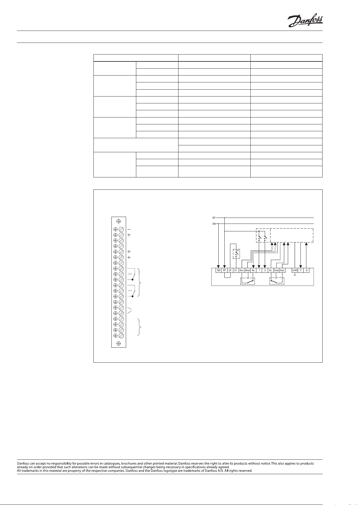
AME 610/613/633 to
AME 655 GA/659 SD
Description AME 610 / 613 / 633 AME 655 GA / 659 SD
Feedback signal
Setpoint
Limit switch
(open)
Limit switch
(clos ed)
Safety device STW/STB/SDB
Power supply
Ground 20 ( - ) GND
Signal 19 ( + ) X (DIP 9 for U/I Selection)
Ground 17 (GND) GND
Current-signal 16 (+ mA) Y (DIP 8 for U/I Selection)
Voltage-signal 15 (+ V)
NC 13 5nc
NO 12 5no
Combined 11 5c
NC 10 4nc
NO 9 4no
Combined 8 4c
6 ST
5 ST
N 4 SN
L 3 SP
PE 1
No longer necessary
(protective insulated housing)
AME 610, 613, 633 AME 655 GA / 659 SD
Output stroke
0(4) - 20 nA
0(2) - 10 V
GND Input
0(4) - 20 nA
0(2) - 10 V
OPEN
End switches
CLOSE
at connection of STB, STW,
remove jumper
N
L
Power supply
230 V AC
PE
4
VN .I R.A1. 02
Produce d by Danfoss A/S © 01/2016
 Loading...