

Page 1

Operating Guide
AMV 130(H), AMV 140(H)
AME 130, 140
AME 130H, 140H
ENGLISH
DANSK
DEUTSCH
NEDERLANDS
ITALIANO
MAGYAR
ČESKY
POLSKI
LIETUVIŲ K.
LATVISKI
AMV + VZ 2 / VZL 2 AMV + VZ 3 / VZL 3 AMV + VZ 4 / VZL 4
Actuators for three point control
AMV 130, AMV 140, AMV 130H, AMV 140H
Motorer til 3-punkts styring
AMV 130, AMV 140, AMV 130H, AMV 140H
Stellantriebe für 3-Pkt.- Schmittsignall
AMV 130, AMV 140, AMV 130H, AMV 140H
Servomotoren met 3-puntssturing
AMV 130, AMV 140, AMV 130H, AMV 140H
Attuatore per il controllo a due punti
AMV 130, AMV 140, AMV 130H, AMV 140H
Szelepmozgatók hárompontos szabályozáshoz
AMV 130, AMV 140, AMV 130H, AMV 140H
Servopohony s tříbodovým regulačním signálem
AMV 130, AMV 140, AMV 130H, AMV 140H
Siłowniki sterowane sygnałem 3-punktowym
AMV 130, AMV 140, AMV 130H, AMV 140H
Pavaros trijų padėčių valdymui
AMV 130, AMV 140, AMV 130H, AMV 140H
Motori trīs punktu kontrolei
AMV 130, AMV 140, AMV 130H, AMV 140H
AMV + AHQM
www.danfoss.com Page 4
www.danfoss.dk Page 5
www.danfoss.de Page 5
www.danfoss.nl Page 6
www.danfoss.com Page 6
www.danfoss.com Page 7
www.danfoss.cz Page 7
www.danfoss.pl Page 8
www.danfoss.lt Page 8
www.danfoss.com Page 9
© Danfoss | 2017.07
VI.KU.L5.9O | 1
Page 2

AMV 130(H), AMV 140(H)
❶
❷
MAINTENANCE
FREE
AMV 130/140, AMV 130H/140H - 24V
5-95 % RH
no condensing
30°
30°
4 – 6 mm × 1 mm 6 mm
❸
①
AMV 130/140, AMV 130H/140H - 230V
AMV 130, 140
❹
①
2 | © Danfoss | 2017.07
②
6 mm
③
④
②
②
①
①
⑤
VI.KU.L5.9O
Page 3
AMV 130(H), AMV 140(H)
mm
AMV 130H, 140H
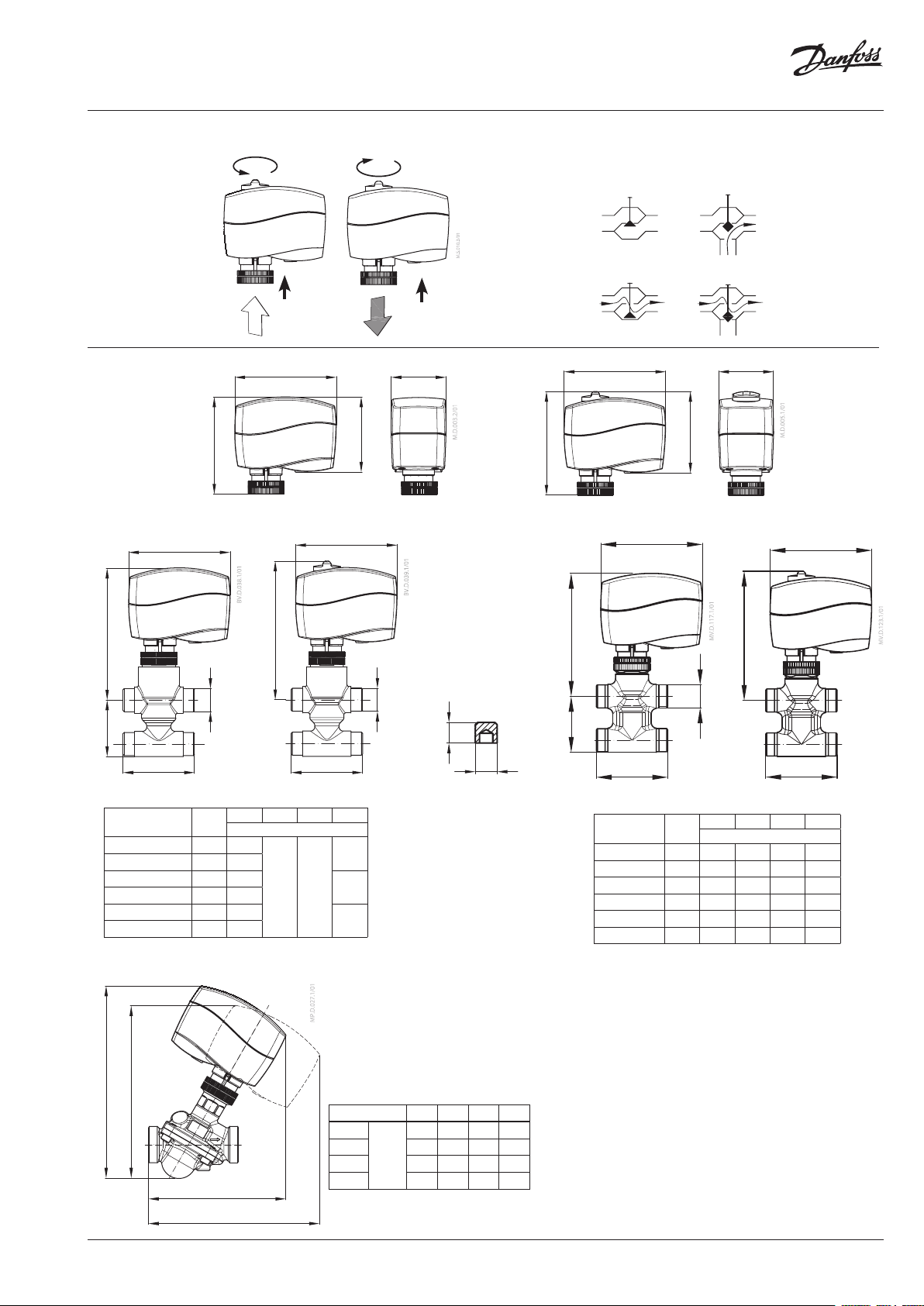
❺
stem up
2 port
3 or 4 port
➏
92
H
h
L
AMV 130/140 +
VZ (DN 15, 20)
Valve t ype d
VZ 2 / DN 15 G ½” 65
VZ 2 / DN 20 G ¾” 77
VZ 3 / DN 15 G ½” 65
VZ 3 / DN 20 G ¾” 77
VZ 4 / DN 15 G ½” 65
VZ 4 / DN 20 G ¾” 77
88
H
d
L H H1h
①
92
68
AMV 130, 140
92
1
L
AMV 130H/140H +
VZ 2, VZ 3, VZ 4 (DN 15, 20)
26.5
119 125
35
65
①
stem down
50
94
d
4.7
Ø5
Stem extension
plug
h
92 50
74
AMV 130H, 140H
92
H
1
L
AMV130/140 + VZL
+ stem exte nsion plug
Valve t ype d
VZL 2 DN 15 G ½” 65 111 117 29.5
VZL 2 DN 20* G ¾” 77 117 123 34.0
VZL 3 DN 15 G ½” 65 111 117 35.0
VZL 3 DN 20 G ¾” 77 117 12 3 35.0
VZL 4 DN 15 G ½” 65 111 117 51.0
VZL 4 DN 20* G ¾” 77 117 123 65.0
* conex valve s DN 20 - G 1 ¹/₈” 14 TPI
1
H
d
L H H1h
92
L
AMV130H/140H + VZL
+ stem exte nsion plug
mm
1
VI.KU.L5.9O
1
2
H
H
DN 15 20 25 32
L
1
L
2
H
1
H
L
1
L
2
2
118 125 141 160
148 156 174 194
mm
168 178 19 6 216
152 162 180 200
© Danfoss | 2017.07 | 3
Page 4

AMV 130(H), AMV 140(H)
24 V
230 V
ENGLISH
Safety Notes
To avoid injury of persons and
damages to the device, it is absolutely
necessary to read and observe these
instructions carefully.
Necessary assembly, start-up, and maintenance
work must be performed by qualified and
authorized personnel only.
Please comply with the instructions of the
system manufacturer or system operator.
Do not remove the cover before th e
power supply is ful ly switched off.
Disposal instruction
This product shou ld be dismantled
and its components so rted, if possible,
in various groups befo re recycling or
disposal.
Always follow the local d isposal regulations.
Mounting ❶
In case of ship applications (on water) actuator
should be mounted with the valve stem in
either 30° above horizontal position or pointing
upwards.
In case of building applications actuator should
be mounted with the valve stem in either
horizontal position or pointing upwards.The
actuator is fixed to the valve body by means
of a ribbed nut which requires no tools for
mounting. The ribbed nut should be tightened
by hand.
Wiring ❷
Grey Stem down
Black Common
Red Stem up
Black Stem down
Blue Common
Brown Stem up
Do not touch anythin g on the PCB!
Lethal voltage!
Installation ❸
1. Check the valve neck. The actuator should
be in steam up position (factory setting).
Ensure that the actuator is mounted securely
on the valve body
2. Wire the actuator according to the wiring
diagram
3. The direction of stem movement can be
observed on the position indicator ①
Manual override
(for service purposes only)
Do not manually o perate the drive if
power is connected!
AMV 130, AMV 140 ❹
① Remove cover
② Insert the Allen key 6 into the spindle
③ Press and hold the button (on the bottom
side of the actuator) during manual override
④ Pull out the tool
⑤ Replace cover
Remark: A ‘click’ sound after energising the
actuator means that the gear wheel has
jumped into normal position.
AMV 130H, AMV 140H ❺
Press and hold the button ① (on the bottom
side of the actuator) during manual override.
Remark: A ‘click’ sound after energising the
actuator means that the gear wheel has
jumped into normal position.
Dimensions ❻
Part Name
部件名称
Connecting nut X O O O O O
连接螺母
O: Indica tes that this hazar dous substance con tained in all of the h omogeneous ma terial for this par t is below the limi t requirement in GB /T 26572;
O: 表示该有害物质在该部件所有均质材料中的含量均在GB/T 26572规定的限量要求以下。
X: Indica tes that this hazar dous substance co ntained in at least o ne of the homogen eous material fo r this part is above th e limit requirem entw in GB/T 26572;
X: 表示该有害物质至少在该部件的某一均质材料中的含量超出GB/T 26572规 定的限量要求。
Lead (P b)
铅 (Pb)
X O O O O O
Mercur y (Hg)
汞 (Hg)
Cadmium (Cd)
镉 (Cd)
Hazardous Substances Table/有害物质含量表
Hexavalent Chromium (Cr(V I))
六价铬 (Cr (VI))
Polybrominated biphenyls (PBB)
多溴联 苯 (PB B)
4 | © Danfoss | 2017.07
Polybrominated diphenyl ethers (PBDE)
多溴二 苯醚 (PBDE)
VI.KU.L5.9O
Page 5

AMV 130(H), AMV 140(H)
24 V
230 V
24 V
230 V
DANSK
Sikkerhedsbestemmelser
For at undgå personskader og
erstatningsskader på produkter, er det
absolut nødvendig at gennemlæse
følgende instruktion.
Montering, opstart og vedligeholdelse må
kun foretages af kvalificeret og autoriseret
personale.
Leverandørens retningslinier skal følges.
Dækslet må ikke f jernes, før
strømforsyningen er fjernet fra
stikkontakten.
Bortskaffelse
Før genbrug eller b ortskaffelse skal
dette produk t skilles ad, og
komponenterne skal sor teres i
forskellige materialegrupper.
Der henvises til de lokal e regulativer for
bortskaffelse.
Montering ❶
I tilfælde af anvendelser ombord på et skib skal
motoren monteres med ventilspindelen i enten
30° over vandret stilling eller pegende opad.
I tilfælde af anvendelser i bygninger skal
motoren monteres med ventilspindelen i enten
vandret eller pegende opad.
Motoren monteres på ventilhuset med en riflet
møtrik, der kan monteres uden værktøj. Den
riflede møtrik skal spændes med håndkraft
El-tilslutning ❷
Grå Spindel ned
Sort Fælle s
Rød Spindel op
Sort Spindel ned
Blå Fælle s
Brun Spindel op
Rør ikke ved noget so m helst på
printkortet! Livsfarlig spænding!
Installation ❸
1. Kontroller ventilens hals. Motoren skal stå
i en position med spindelen trukket op.
(fabriksindstilling). Kontroller, at motoren er
monteret solidt på ventilhuset.
2. Tilslut motoren iht. ledningsdiagrammet – se
“El-tilslutning“.
3. Spindelens bevægelsesretning kan ses på
positionsindikatoren ①.
Manuel overstyring
Motoren må ikke betje nes manuelt,
når spændingen e r tisluttet!
AMV 130, AMV 140 ❹
① Tag dækslet af.
② Sæt en unbrakonøgle nr. 6 i spindelen.
③ Tryk på knappen (på undersiden af motoren)
og hold den inde under en manuel
overstyring.
④ Træk værktøjet ud.
⑤ Sæt dækslet tilbage på plads på motoren.
Bemærk:
Hvis der høres en klik-lyd, efter at spændingen
er sluttet, bet yder det, at tandhjulet er drejet
ind i normal position.
AMV 130H, AMV 140H ❺
① Tryk på knappen (på undersiden af motoren)
og hold den inde under en manuel overstyring.
Bemærk:
Hvis der høres en klik-lyd, efter at
strømforsyningen er sluttet til motoren,
betyder det, at tandhjulet er drejet i normal
position.
Mål ❻
DEUTSCH
Sicherheitshinweise
Um Verletzungen an Personen und
Schäden am Gerät zu vermeiden,
diese Anleitung unbedingt beachten.
Montage, Inbetriebnahme und
Wartungsarbeiten dürfen nur von sachkundigen
und autorisierten Personen durchgeführt
werden.
Die Vorgaben des Anlagenherstellers und
Anlagenbetreibers sind zu beachten.
Abdeckung erst e ntfernen, wenn die
Stromversorgung komplett
ausgeschaltet ist.
Anweisung zur Entsorgung
Dieses Produkt so llte ausgebaut und in
dessen Bestandteile zerle gt werden.
Sortieren Sie di e einzelnen
Bestandteile entspreche nd der
Entsorgungsgruppe n zur Wiederverwe rtung
oder Entsorgung. Be achten sie dabei immer die
lokalen Entsorgungsrichtlinien.
Montage ❶
Bei Schiffsanwendungen (auf dem Wasser) sollte
der Stellmotor so installiert werden, dass die
Ventilspindel entweder 30° steiler als horizontal
ausgerichtet ist oder nach oben zeigt
Beim Einsatz in Gebäuden sollte der Stellmotor
so installiert werden, dass die Ventilspindel
entweder horizontal ausgerichtet ist oder nach
oben zeigt.
Der Stellantrieb wird am Ventilgehäuse mittels
einer Rändelschraube befestigt, für die kein
besonderes Werkzeug nötig ist. Diese Schraube
wird mit der Hand angezogen.
Verdrahtung ❷
Antriebsstange
Grau
ausfahrend
Schwarz Nullleiter
Antriebsstange
Rot
einfahrend
Antriebsstange
Schwarz
ausfahrend
Blau Nullleiter
Antriebsstange
Braun
einfahrend
Bitte die Platine nicht dire kt berühren!
Lebensgefahr!
Einbau ❸
1. Überprüfen Sie den Anschluss am Ventil.
Die Antriebsstange des Stellantriebs sollte
eingefahren sein. Stellen Sie sicher, dass
der Stellantrieb fest auf dem Ventilkörper
montiert ist.
2. Schließen Sie den Stellantrieb entsprechend
dem Verdrahtungsplan - oben an
“Verdrahtung“.
3. Die Bewegungsrichtung der Antriebsstange
kann an der Positionsanzeige überprüft
werden ①.
Manuelle Hubverstellung
(nur zu War tungszwecken)
Verstellen Sie den Antrieb nicht vo n
Hand, solange er unte r Strom steht!
AMV 130, AMV 140 ❹
① Deckel abnehmen.
② Den Inbusschlüssel in die Antriebsstange
stecken.
③ Knopf (auf der Unterseite des Stellantriebs)
drücken und während der manuellen
Hubverstellung gedrückt halten.
④ Werkzeug entfernen.
⑤ Deckel wieder auf den Stellantrieb setzen.
Anmerkung: Der hörbare „Klick “ nach dem
Einschalten der Stromzufuhr zeigt, dass das
Getriebe in Normalstellung eingerastet ist.
AMV 130H, AMV 140H ❺
Knopf (auf der Unterseite des Stellantriebs)
① drücken und während der manuellen
Hubverstellung gedrückt halten.
Die Hubverstellung erfolgt durch das
Drehen des Handrades auf der Oberseite des
Stellantriebs.
Anmerkung: Der hörbare „Klick “ nach dem
Einschalten der Stromzufuhr zeigt, dass das
Getriebe in Normalstellung eingerastet ist.
Abmessungen ❻
VI.KU.L5.9O
© Danfoss | 2017.07 | 5
Page 6

AMV 130(H), AMV 140(H)
24 V
230 V
24 V
230 V
NEDERLANDS
Veiligheid
Om verwondingen van personen en
schade aan het apparaat te
voorkomen dient men deze instructies
met aandacht te lezen.
Montage, inbedrijfstelling en
onderhoudswerkzaamheden mogen alleen
door deskundig en erkend personeel uitgevoerd
worden.
Neem alle instructies betreffende
installatiecomponenten van andere fabrikanten
in acht.
Verwijder de afdek kap niet voordat de
voedingsspanning volle dig is
uitgeschakeld.
Afvalverwerking
Dit product of delen ervan dienen te
worden afgevoerd op een
milieuverantwoorde wijze.
Apparatuur die elektrische onderdelen bevat,
mag niet samen met huishoudelijk afval
worden afgevoerd.
Deze apparatuur moet apart worden
ingezameld samen met ander elek trisch
en elektronisch afval conform de geldende
wetgeving.
Montage ❶
Wanneer de servomotoren op een schip
worden toegepast dan dient de positie van
de afsluiterspindel minimaal 30° boven het
horizontale vlak gemonteerd te zijn.
Wanneer de servomotoren in een gebouw
worden toegepast dan dient de afsluiterspindel
tussen een horizontale- en een naar boven
wijzende positie gemonteerd te zijn.
De servomotor wordt op de afsluiter
gemonteerd d.m.v. het aandraaien van de
gekartelde ring onder de servomotor. Deze
ring mag uitsluitend met de hand worden
vastgezet..
Elektrische aansluiting ❷
grijs spindel omlaag
gemeenschappe-
zwart
lijk (nul)
rood spindel omhoog
zwart spindel omlaag
gemeenschappe-
blauw
lijk (nul)
bruin spindel omhoog
Gevaarlijke spanning, raak n iets aan
op de printplaat.
Installatie ❸
1. Controleer of de servomotor op de afsluiter
past. De servomotor dient in de geopende
stand te staan. (fabrieksinstelling) Controleer
of de servomotor goed is bevestigd op de
afsluiter.
2. Sluit de servomotor aan volgens het
bovenstaande aansluitschema.
3. De richting van de spindel kan afgelezen
worden aan de positie van de indicator aan
de onderzijde van de servomotor ①.
Handbediening
Maak geen gebr uik van de
handbediening wanneer de
servomotor ond er spanning staat!
AMV 130, AMV 140 ❹
① Verwijder de afdekkap.
② Steek de imbussleutel 6 in de spindel.
③ Houd de knop aan de onderzijde van de
servomotor ingedrukt gedurende het
verdraaien van de spindel.
④ Verwijder de sleutel.
⑤ Plaats de afdekkap terug op de servomotor.
Opmerking: Wanneer de servomotor weer
onder spanning wordt ge zet, is er een ˝ klik˝
hoorbaar, dit wil zeggen dat de aandrijving
weer in de normale positie staat.
AMV 130H, AMV 140H ❺
Houd de knop ① aan de onderzijde van
de servomotor ingedrukt gedurende het
verdraaien van de handbediening aan de
bovenzijde van de servomotor.
Opmerking: Wanneer de servomotor weer
onder spanning wordt ge zet, is er een ˝ klik˝
hoorbaar, dit wil zeggen dat de aandrijving
weer in de normale positie staat.
Afmetingen ❻
ITALIANO
Nota di sicurezza
Per evitare danni alle persone e
all’apparecchio, è assolutamente
necessario leggere e osservare
attentamente queste istruzioni.
Montaggio, avviamento e manutenzione
devono essere eseguiti solo da personale
autorizzato e qualificato.
Seguire sempre le istruzioni del costruttore o
dell’assistenza.
Non rimuovere il coperchio p rima di
aver completamente scollegato
l’alimentazione elettrica.
Istruzioni per lo smaltimento
Questo prodot to deve essere smontato
e i componenti smistati, se possibile ,
prima di procedere con il ri ciclaggio o lo
smaltimento.
Seguire sempre le nor mative locali sullo
smaltimento.
Montaggio ❶
Nel caso di applicazioni navali (in acqua)
l’attuatore deve essere montato con lo stelo
valvola orientato a 30° rispetto alla posa
orizzontale o rivolto verso l’alto.
In caso di applicazioni residenziali l’attuatore
può essere montato con lo stelo valvola in
posizione orizzontale o rivolto verso l’alto.
L’attuatore è fissato sul corpo valvola tramite un
dado nervato, la cui installazione non richiede
l’uso di alcun attrezzo. Il dado va serrato a mano.
Collegamento elettrico ❷
Grigio gambo abbassato
Nero Comune
Rosso gambo abbassato
Nero gambo abbassato
Blu Comune
Marrone gambo abbassato
Non toccare i componenti del P CB!
Tensione mortale!
Installazione ❸
1. Controllare il collo della valvola. L’attuatore
deve trovarsi in posizione gambo valvola
completamente esteso (impostazione di
fabbrica). Assicurarsi che l’attuatore sia
saldamente fissato sul corpo valvola.
2. Collegare l’attuatore secondo lo schema
elettrico.
3. La direzione del movimento dello stelo
può essere osservata sull’indicatore di
posizione ①
Override manuale
(solo per manutenzione/assistenza)
Non azionare manu almente l’unità
se alim entata!
AMV 130, AMV 140 ❹
① Rimuovere il coperchio
② Inserire la chiave esagonale di 6 mm
nell’alberino
③ Premere senza rilasciare il pulsante
(sulla base dell’attuatore) durante l’ovverride
manuale
④ Rimuovere l’attrezzo
⑤ Rimontare il coperchio
Nota: Un “clic” dopo l’eccitazione
dell’attuatore indica che la ruota dentata si è
innestata nella sua posizione normale.
AMV 130H, AMV 140H ❺
Premere senza rilasciare il pulsante ①
(sulla base dell’attuatore) durante il controllo
manuale.
Nota: Un “clic” dopo l’eccitazione
dell’attuatore indica che la ruota dentata si è
innestata nella sua posizione normale.
Dimensioni ❻
6 | © Danfoss | 2017.07
VI.KU.L5.9O
Page 7

AMV 130(H), AMV 140(H)
24 V
230 V
24 V
230 V
MAGYAR
Biztonsági megjegyzések
Az itt szereplő utasítások gondos
elolvasása és betartása feltétlenül
fontos a személyi sérülések és
berendezés károsodások elkerülésére.
A szükséges szerelési, beállítási és
munkákat kizárólag szakképzett
személyzet végezheti el.
Kérjük, tartsa be a rendszer gyártójának és
üzemeltetőjének rendelkezéseit!
Ne távolítsa el a fedelet a
tápfeszültség teljes lekapcsolása
előtt.
Hulladék tárolási instrukció
Ezt a terméket s zét kell szerelni és
annak alkatrészeit szét válogatni
amennyiben lehetséges különböző
csoportok s zerint az újrahasznosítás vagy a
szemétbe dobás e lőtt.
Mindig keresse a helyi s zemét lerakási helyeket!
Beépítés ❶
Hajózási alkalmazásoknál, a hajtás a vízszintestől
minimum 30°-os szögben elforgatva vagy felfelé
nézően függőleges helyzetben építhető be.
Épületgépészeti alkalmazásoknál a hajtás
vízszintes helyzetben ill. a vízszintes helyzettől
felfelé irányulóan építhető be.
karbantartási
és megbízott
A szelepmozgató a szeleptesthez egy recézett
anyával van rögzítve, - szerszán nélküli szerelés.
A recézett anyát kézzel kell meghúzni.
Elektromos bekötés ❷
Szürke Szelepszár le
Fekete Közös
Piros Szelepszár fel
Fekete Szelepszár le
Kék Közös
Barna Szelepszár fel
A nyomtatott áramköri kárt yán
semmit ne érintsen meg ! Halált okozó
feszültség!
Beépítés ❸
1. Ellenőrizze a szelepnyak helyzetét.
A szelepmozgatót felfelé mutató
szelepszárra kell felszerelni.(gyári beállítás).
Bizonyosodjon meg a szelepmozgató
szeleptestre történő biztonságos
rögzítéséről.
2. Kösse be a szelepmozgatót a huzalozási rajz
szerint – lásd “Elektromos bekötés“.
3. A szelepszár mozgás iránya megfigyelhető a
pozíció kijelzőn ①.
Kézi működtetés
(csak szerviz esetén)
Feszültség alatti h elyzetben kézzel ne
működtesse a szelepet!
AMV 130, AMV 140 ❹
① Távolítsa el a szelepmozgató fedelét.
② Helyezze a 6mm-es imbusz-kulcsot az
orsóba.
③ Kézi működtetés során nyomja meg és
tartsa nyomva a szelepmozgató alsó részén
elhelyezett gombot.
④ Húzza ki az imbusz-kulcsot.
⑤ Helyezze vissza a fedelet a szelepmozgatóra.
Megjegyzés: A szelepmozgató
tápfeszültségre kapcsolása utáni „kattanás”
azt jelenti, hogy a fogaskerék normál
pozícióba ugrott.
AMV 130H, AMV 140H ❺
Kézi működtetés során ① nyomja meg és
tartsa nyomva a szelepmozgató alsó részén
elhelyezett gombot.
Megjegyzés: A szelepmozgató
tápfeszültségre kapcsolása utáni „kattanás”
azt jelenti, hogy a fogaskerék normál
pozícióba ugrott.
Méretek ❻
ČESKY
Bezpečnostní pokyny
Abyste předešli zranění osob a
poškození zařízení, před montáží a
uváděním zařízení do provozu si musíte
přečíst tyto pokyny a bezpečnostní instrukce.
Nedemontujte servopohony s funkcí
bezpečnostní pružiny! Při nesprávné manipulaci
hrozí nebezpečí zranění nebo usmrcení!
Servopohon je těžký. Manipulujte s ním opatrně,
abyste předešli zranění osob nebo poškození
produktu.
Nesundávejte kryt, dokud není
napájení zcela vypnuto.
Pokyny pro likvidaci
Tento výrobek by měl být před
recyklací nebo likvidací rozebrán na
součástky a ty u místěny do různých
skupin odpadu.
Vždy dbejte aktuál ních pokynů místní
legislativy.
Montáž ❶
V případě lodních aplikací (na vodu) by měl být
pohon instalován s vřetenem ventilu buď 30%
nad horizontální pozicí nebo směrem nahoru.
V případě aplikací v budovách by měl být pohon
instalován s vřetenem ventilu buď v horizontální
pozici nebo směrem nahoru.
Servopohon je k tělesu ventilu připojen pomocí
drážkované převlečné matice. K montáži není
potřeba používat žádné nářadí.
Zapojení ❷
Šedá Vřeteno dolů
Černá Společný
Červená Vřeteno nahoru
Černá Vřeteno dolů
Modrá Společ ný
Hnědá Vřeteno nahoru
V žádném případě se ne dotýkejte
žádné součásti desky s p lošnými
spoji! Přítomnost napě tí nebezpečné
životu!
Instalace ❸
1. Zkontrolujte připojovací hrdlo ventilu.
Servopohon je potřeba montovat s
vřetenem nastaveným do horní polohy
(tovární nastavení). Ujistěte se, že
servopohon je k tělesu ventilu správně
namontován.
2. Servopohon zapojte dle schéma zapojení-viz
“Zapojení“.
3. Směr pohybu vřetena je možné sledovat
pomocí indikátoru polohy ①.
Ruční ovládání
(pouze pro servisní účely)
Je-li ser vopohon pod napětí m, tak se
ho nikdy nesnažte ovládat ručně!
AMV 130, AMV 140 ❹
① Sejměte kryt servopohonu.
② Do vřetena zasuňte imbusový klíč číslo 6.
③ Na spodní straně servopohonu stiskněte
tlačítko a držte ho stisknuté po celou dobu
ručního ovládání.
④ Vytáhněte klíč.
⑤ Kryt nainstalujte zpět na servopohon.
Poznámka: Ozve-li se po připojení na zdroj
elektrické energie slyšitelné cvaknutí, tak
to znamená, že převodové kolo zapadlo do
správné polohy.
AMV 130H, AMV 140H ❺
Na spodní straně servopohonu stiskněte tlačítko
a držte ho stisknuté po celou dobu ručního
ovládání ①.
Poznámka: Ozve-li se po připojení na zdroj
elektrické energie slyšitelné cvaknutí, tak
to znamená, že převodové kolo zapadlo do
správné polohy.
Rozměry ❻
VI.KU.L5.9O
© Danfoss | 2017.07 | 7
Page 8

AMV 130(H), AMV 140(H)
24 V
230 V
24 V
230 V
POLSKI
Warunki bezpieczeństwa
Aby uniknąć obrażeń u ludzi oraz
uszkodzenia sprzętu, należy
koniecznie zapoznać się z tymi
informacjami i przestrzegać ich.
Niezbędne prace związane z montażem,
uruchomieniem i konserwacją mogą być
wykonywane wyłącznie przez autoryzowany i
wykwalifikowany personel.
Należy postępować zgodnie z instrukcjami
producenta lub operatora systemu.
Nie zdejmować obud owy przed
całkowitym odłączeniem napięcia
zasilania.
Instrukcja usuwania odpadów
Ten produkt powinien być rozebrany a
jego komponent y posegregowane,
jeśli to możliwe, na różne gru py przed
poddaniem rec yklingowi lub utyli zacji.
Zawsze stosuj się do miejscowych pr zepisów w
zakresie usuwania odpadów.
Montaż ❶
W przypadku aplikacji do instalacji na statku (na
wodzie) siłownik powinien być zamontowany
tak, aby trzpień zaworu był w położeniu pod
kątem 30° powyżej poziomu lub był skierowany
do góry.
W przypadku aplikacji do instalacji w budynkach
siłownik powinien być zamontowany tak, aby
trzpień zaworu był w pozycji poziomej lub
skierowany do góry.
Siłownik jest montowany na zaworze za
pomocą karbowanej nakrętki, nie wymagającej
stosowania narzędzi. Nakrętkę należy dokręcić
ręcznie.
Podłączenia elektryczne ❷
Szary Trzpień w dół
Czarny Wspólny
Czerwony Trzpień w górę
Czarny Trzpień w dół
Niebieski
Wspólny
Brązowy Trzpień w górę
Nie dotykać nic zego na płytce
drukowanej. Napięcie niebezpieczne
dla życia!
Montaż ❸
1. Sprawdzić szyjkę zaworu. Siłownik powinien
być w pozycji podniesionego trzpienia
zaworu (ustawienie fabryczne). Upewnić
się, że siłownik został zamontowany we
właściwy sposób.
2. Podłączyć do siłownika zasilanie elektryczne
zgodnie z podanym schematem (patrz
powyżej).
3. Sprawdzić kierunek ruchu trzpienia
obserwując wskaźnik położenia
(pozycjoner) ①.
Sterowanie ręczne
(tylko w celach serwisowych)
Nie wolno uży wać sterowania
ręcznego, je żeli siłownik jest pod
napięciem!
AMV 130, AMV 140 ❹
① Zdjąć pokrywę.
② Wsunąć klucz imbusowy 6 do otworu we
wrzecionie.
③ Podczas sterowania ręcznego kluczem
imbusowym przycisnąć i przytrzymać
przycisk znajdujący się pod spodem
siłownika.
④ Wyciągnąć klucz imbusowy.
⑤ Założyć pokrywę na siłownik.
Uwaga: “Kliknięcie” po załączeniu zasilania
elektrycznego oznacza, że koło zębate
wskoczyło w normalną pozycję roboczą.
AMV 130H, AMV 140H ❺
Podczas sterowania ręcznego przycisnąć
i przytrzymać przycisk znajdujący się pod
spodem siłownika ①.
Uwaga: „Kliknięcie” po załączeniu zasilania
elektrycznego oznacza, że koło zębate
wskoczyło w normalną pozycję roboczą.
Wymiary ❻
LIETUVIŲ K.
Saugos informacija
Siekiant išvengti traumų ir įrenginio
gedimų, būtina atidžiai perskaityti šias
instrukcijas ir jomis vadovautis.
Būtiną montavimą, paleidimą ir techninį
aptarnavimą turi atlikti tik kvalifikuotas
įgaliotasis personalas.
Rekomenduojame laikytis sistemos gamintojų
sistemos operatoriaus instrukcijų.
Nenuimkite dangtelio, kol
maitinimas bus visiškai išjungtas.
Sunaikinimo instrukcija
Šis gaminys turi būti išmontuotas ir jo
dalys surūšiuotos, jei įmanoma, pagal
atskiras medžiagų grup es, prieš
sunaikinant.
Vadovaukitės vietinėmis sunaikinimo
nuostatomis.
Montavimas ❶
Naudojant pavarą laivų sistemose (vandenyje),
ją reiktų montuoti taip, kad pavaros stiebas būtų
30° virš horizontalios padėties arba nukreiptas
į viršų.
Naudojant pavarą pastatų sistemose, ją reiktų
montuoti taip, kad pavaros stiebas būtų
horizontalioje padėtyje arba nukreiptas į viršų.
arba
Pavara prie vožtuvo korpuso prisukama
rantuota veržle, todėl montavimui nereikalingi
jokie įrankiai. Rantuota veržlė priveržiama ranka.
Elektriniai sujungimai ❷
Pilka Stiebu žemyn
Įprastinė padėtis
Juoda
Raudona
Stiebu žemyn
Juoda Stiebu žemyn
Įprastinė padėtis
Mėlyna
Ruda Stiebu žemyn
Nelieskite jokių da lių, esančių ant
montažinės plokštės! Įtampa
pavojinga gyvybei!
Montavimas ❸
1. Patikrinkite vožtuvo ir pavaros jungimą.
Pavaros stiebas turi būti viršutinėje padėtyje
(gamintojo nustatymas). Tvirtai sujunkite
pavarą su vožtuvo korpusu.
2. Prijunkite prie pavaros elektros laidus pagal
aukščiau pateiktą sujungimų schemą.
3. Pavaros stiebo judėjimo kryptį rodo padėties
indikatorius ①.
Rankinis valdymas
(tik techninės priežiūros tikslais)
Rankiniu būdu nevald ykite pavaros,
prie kurios prijungtas ele ktros
maitinimas!
AMV 130, AMV 140 ❹
① Nuimkite dangtelį.
② Į vožtuvo stiebą įkiškite 6 numerio “Allen”
raktelį.
③ Rankiniu būdu sukdami pavarą, paspauskite
ir laikykite mygtuką, esantį pavaros apačioje.
④ Ištraukite įrankį.
⑤ Vėl uždėkite pavaros dangtelį.
Pastaba: Įjungus pavarą, spragtelėjimas
rodo, kad pavaros krumpliaratis įėjo į
normalią padėtį.
AMV 130H, AMV 140H ❺
Rankiniu būdu sukdami pavarą, paspauskite ir
laikykite mygtuką, esantį pavaros apačioje ①.
Pastaba: Įjungus pavarą, spragtelėjimas
rodo, kad pavaros krumpliaratis įėjo į
normalią padėt.
Matmenys ❻
8 | © Danfoss | 2017.07
VI.KU.L5.9O
Page 9

AMV 130(H), AMV 140(H)
24 V
230 V
LATVIEŠU
Informācija par drošību
Lai novērstu traumu gūšanas un ierīces
bojājumu risku, obligāti rūpīgi jāizlasa
un jāievēro šie norādījumi.
Nepieciešamā montāža, palaišana un apkope
jāveic tikai kvalificētiem un pilnvarotiem
darbiniekiem.
Lūdzu, ievērojiet sistēmas izstrādātāja vai
sistēmas operatora norādījumus.
Nenoņemiet vāku, p irms strāvas
padeve nav pilnībā izslēgta.
Utilizācijas instrukcija
Šis produkts ir jād emontē pa daļām un
tā komponentes ir jāšķiro dažādās
grupās pirms otreizējās pār strādes vai
utilizācijas.
Vienmēr ievērojiet vietējo likumdošanu
attiecībā uz atkr itumu apsaimniekošanu.
Uzstādīšana ❶
Pielietojuma gadījumā uz kuģa (uz ūdens)
izpildmehānisms jāuzstāda ar vārsta pamatni
30° virs horizontālā stāvokļa vai virzienā uz
augšu.
Pielietojuma gadījumā būvniecībā
izpildmehānisms jāuzstāda ar vārsta pamatni
horizontālā stāvoklī vai virzienā uz augšu.
Izpildmehānisms tiek piestiprināts pie vārsta ar
rievotu uzgriezni, kuram nav nepieciešami citi
instrumenti. Rievotais uzgrieznis ir jāpievelk ar
roku.
Elektroinstalācija ❷
Pelēks Kā ts uz leju
Melns Kopējs
Sarkans Kāts uz au gšu
Melns Kāts uz leju
Zils Kopējs
Brūns Kāts u z augšu
Neaiztiecie t neko, kas atrodas uz PBC!
Nāvējošs spriegu ms!
Instalācija ❸
1. Pārbaudiet vārsta kātu. Izpildmehānismam
ir jāatrodas ar vārsta kātu uz augšu.
Pārliecinieties, ka izpildmehānisms ir droši
piemontēts pie vārsta.
2. Pieslēdziet izpildmehānismu, izmantojot
elektroinstalācijas diagrammu – skat.
“Elektroinstalācija“.
3. Mehānisma kustības virzienu var noteikt pēc
indikatora stāvokļa ①.
Brīdinājuma instrukcija
Neaiztiecie t ar rokām dzinēju, kas
atrodas zem sprieguma!
AMV 130, AMV 140 ❹
① Noņemiet vāciņu.
② Ievietojiet kātā Allen 6. atslēgu.
③ Piespiediet un paturiet pogu
(izpildmehānisma apakšdaļā).
④ Izņemiet instrumentu.
⑤ Novietojiet vāciņu atpakaļ uz motora.
Piezīme: Klikšķa skaņa pēc motora
pieslēgšanas nozīmē, ka zobrats ir pārlecis
normālā stāvoklī.
AMV 130H, AMV 140H ❺
Piespiediet un paturiet pogu (izpildmehānisma
apakšdaļā) ①.
Piezīme: Klikšķa skaņa pēc motora
pieslēgšanas nozīmē, ka zobrats ir pārlecis
normālā stāvoklī.
Izmēri ❻
VI.KU.L5.9O
© Danfoss | 2017.07 | 9
Page 10

AMV 130(H), AMV 140(H)
10 | © Danfoss | 2017.07
VI.KU.L5.9O
Page 11

AMV 130(H), AMV 140(H)
VI.KU.L5.9O
© Danfoss | 2017.07 | 11
Page 12

Danf
already on order pro
All trademarks in this material are property of the respec
AMV 130(H), AMV 140(H)
oss can accept no responsibility for possible errors in catalogues, brochures and other printed material. Danfoss reserves the right to alter its products without notice. This also applies to products
vided that such alterations can be made without subsequential changes being necessary eady agreed.
12 | © Danfoss | DHS-SRMT/SI | 2017.07
tive companies. Danfoss and the Danfoss logotype are trademarks of Danfoss A/S. All rights reserved.
73690980 / VI.KU.L5.9O
 Loading...