

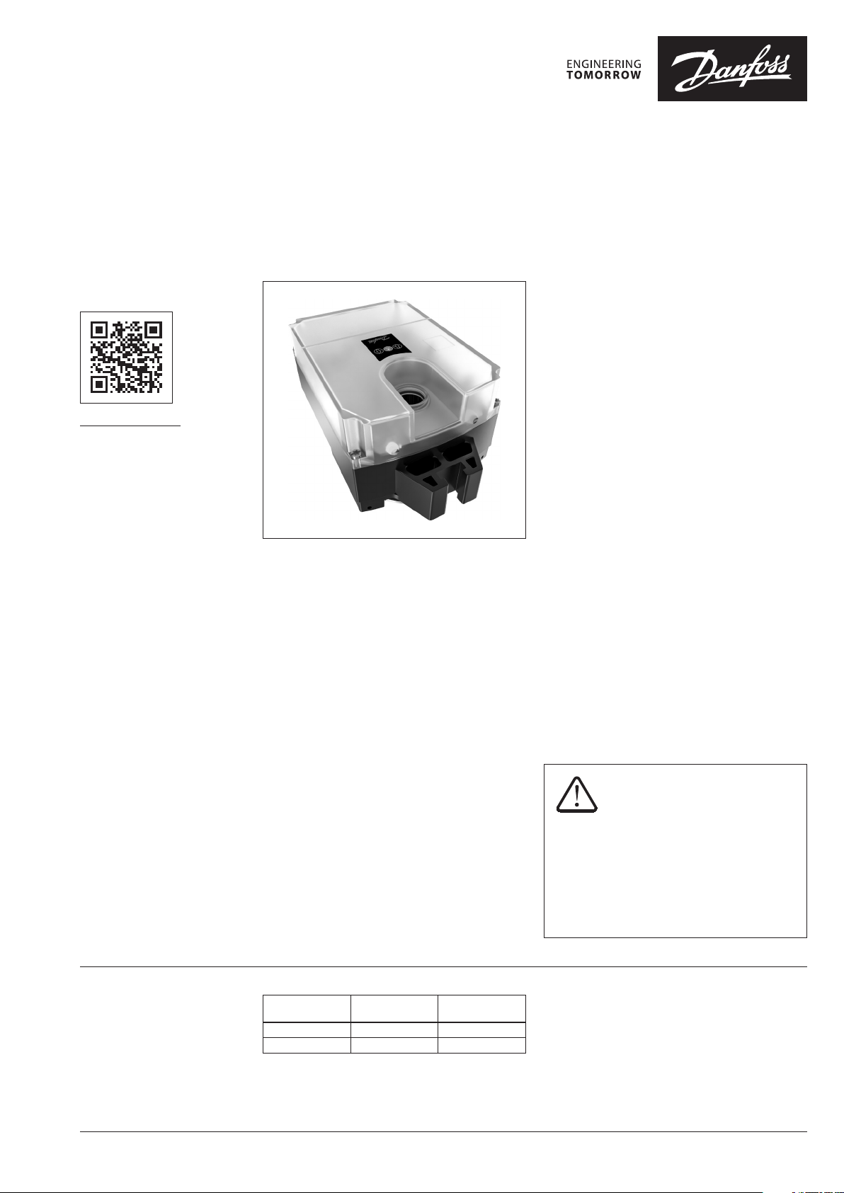
Data sheet
Intelligent electrical actuator
AMEi 6 iSET
Description
virtus.danfoss.com
AMEi 6 iSET actuator for intelligent optimization
of the District Heating/Cooling substation
operation. Automatic adjustment of Δp setting
on AFP 2, AFPQ 2 and AFQMP 2 controllers, used
in DHC systems.
Solution for dynamic DH systems with wide span
of min - max ow (Domestic Hot Water service)
and for systems with improperly sized control
equipment (oversized control valves, wrong
valve selection/characteristic, poor control
ratio...)
Auto stabilization function monitors control
signal and stabilizes oscillations at the partial/
low load operating conditions, by adjustment of
the Δp over the motorized control valve (MCV).
Constant-real time MCV operation improvement
led to more stable control without oscillations
and ow delivered up to the real needs
(overow prevention).
This results in stable temperature conditions
on the secondary side, improvement of ΔT on
the primary side and longer lifetime of installed
equipment.
Features:
· Auto stabilization function
· Electrical manual operation
· Position indication, LED signalization
· Adjustable min/max Δp setting by the end
switch (adjustable stroke limitation of the
pressure actuator)
· Thermal and overload protection
· External reset button
· Easy mounting, pre-fixing with the wire lock
· Anti-rotation strap for preventing actuator
from rotating
· Automatic calibration to the pressure actuator
stroke-reduced commissioning time
· Maintenance free
· Voltage or current input/output signal Y/X
· Modbus RS485
·
Galvanic insulation Y, X
· Equipped with cable glands
Main Data:
· Nominal voltage:
- 24 V ac/dc, 50/60 Hz
- 230 V ac, 50/60 Hz
· Control input signal: modulating
· Torque: 7 Nm
· Speed 36 s/turn (18 sec/mm)
· Full stroke time ~30 min
· Compatible with modulating 24 V and 230 V
actuators AME 20/23/30/33, AME 55/56, AME
85/86, AME 655/655GA/658/659
· Compatibility with 3 point AMV actuators not
available yet
iSET is not the solution for disturbances
and oscillations coming from the
network.
External oscillations generated by the other
substations, disturbances because of the
poor control at the heat source, or poor
network balancing in general are out of the
iSET range and can’t be managed.
Ordering
© Danfoss | 2021.06 AI303648130321en-010202 | 1
Typ e
AMEi 6 iSET 230 ac 082G4300
AMEi 6 iSET 24 ac /dc 082G4301
Supply voltage
(V)
Code No.
Data sheet AMEi 6 iSET
Technical data
Please check power supply
and power consumption prior
connection!
Actuator type AMEi 6 iSE T
Power supply V 24 V ac/dc or 230 V ac; +10...-15%
Power consumption VA
Frequency Hz 50/60
Control input Y
Control output X
Torque Nm 7
Speed s/turn 36
Full stroke time min 30
Max. medium temperature
Ambient temperature 0 … + 55
Storage and transport temperature – 40... +70 (storing for 3 days)
Humidity 5-95% (no condensing)
Protection class
Grade of enclosure IP 54
Weight kg 2.5
Manual operation Electrical
Power failure response Actuator remains in last position
- marking in accordance with the standards
V 0-10 (2-10) [Ri = 40 kΩ]
mA 0-20 (4-20) [Ri = 500 Ω]
V 0-10 (2-10) [Ri = 10 kΩ]
mA 0-20 (4-20) [Ri = 510 Ω]
Depends on valve type. No limitations for 150 °C
°C
Low Voltage Directive (LVD) 2014/35/EU: EN 60730-1, EN 60730-2-14
Electromagnetic Compatibility Directive (EMC) 2014/30/EU: EN 61000-6-2,
EN 61000-6-3
8 (24V)
16 (230V )
230V- protection class II
24V- protection class III
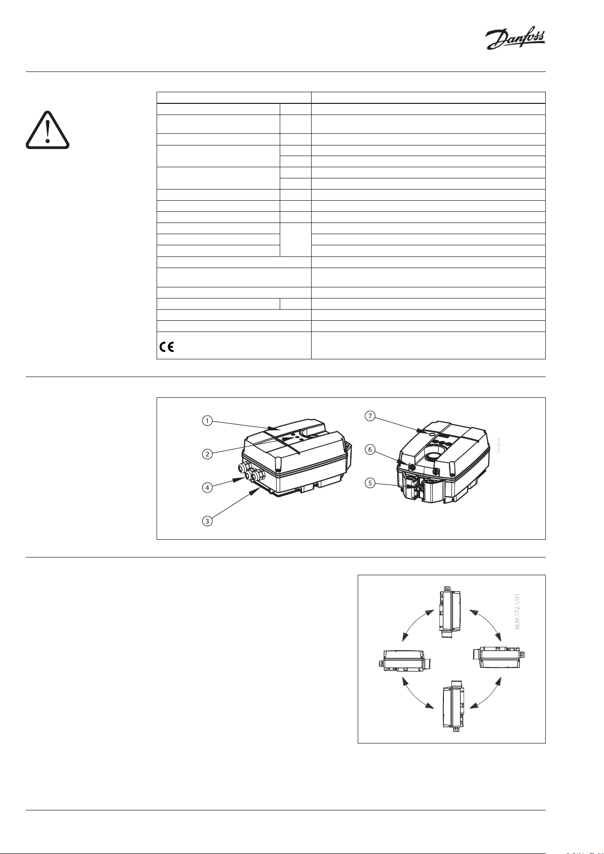
Design
1. Service cover
2. Function buttons
3. Wire lock
4. Cable gland
5. End switch
6. LED signalization for actuator
operating modes
7. LED signalization for Modbus
communication status
Installation The actuators should be mounted in a dry
environment.
In case of outdoor installation, the actuator
has to be protected against climatic influences
by suitable measures. For exact installation
instruction manuals for relevant pressure
actuator should be followed.
Mechanical
Please check the allowed installation positions
for the valve and pressure actuator. AMEi
6 actuator can be installed in all positions
(seescheme). Allow for necessary clearance for
maintenance purposes (see section Dimensions).
Electrical connection
Electrical connections can be accessed by
removing the service cover.
2 | AI303648130321en-010202 © Danfoss | 2021.06
Data sheet AMEi 6 iSET
AMEi 6 iSET
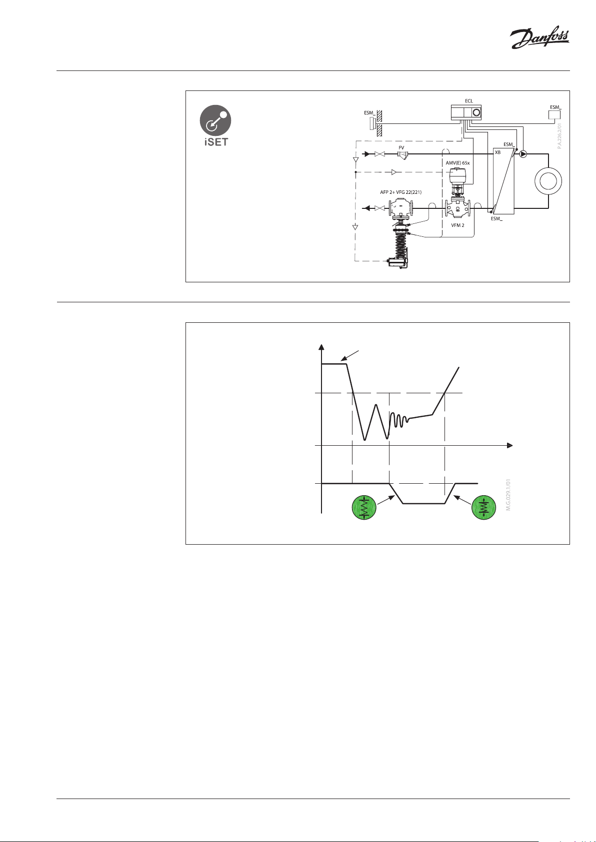
Application principle
Example:
- Indirectly connected
heating system
- Return mounting
- Analog voltage signal
Auto stabilization function
control signal (from controller)
MCV position
Threshold
(% of valve opening)
iSET ∆p setting
P2
P1
P3
∆p For design flow
Fig. 1
Auto stabilization function (ASF)
iSET Auto Stabilization Function (ASF) constantly monitors control signal.
In case of appearing signal oscillations, iSET algorithm detects the oscillations and automatically
adjusts differential pressure (Δp ) over the motorized control valve (MCV) by changing the Δp setting
on the differential pressure controller.
This is done by stretching and squeezing the setting spring on the pressure actuator, until the control
signal is stabilized. Result is more stable operation conditions of MCV and improved substation/
system efficiency.
Operation principle (Fig . 1)
Auto Stabilization Function (ASF) searches for 3 consecutive peaks (P1, P2, P3) in control signal. When
peaks are detected and when the MCV position is below treshold, ASF calculates needed Δp reduction,
and reduces set Δp over the MCV by stretching the spring on the pressure actuator. When calculated point
is reached, it stops.
In case of repeating oscillations, procedure repeats, until the oscillations are eliminated and MCV is
opened more than 50% (factory set treshold of the valve stroke/control signal).
As soon as the control signal crosses threshold value, iSET moves towards to the initially set Δp (Δp set for
design flow conditions).
If the control signal is stable and below threshold, iSET remains in position.
To prevent the oscillations after the system is stabilized, ASF function monitors not only oscillations,
but also analyses type of control signal (slow damping, suitable damping, too strong damping…).
Based on signal specifics it provides proper reaction (Δp correction).
AI303648130321en-010202 | 3© Danfoss | 2021.06

Data sheet AMEi 6 iSET
Actuator operating modes
LED operating mode indicator
The three-colour (green/yellow/red) LED function indicators are located at the front of actuator top
cover. They indicate different operating modes.
RESET button
Actuators AMEi 6 iNET/iSET have external RESET button which is located on top cover of the actuator .
With this button you can enter or exit Stand-By mode (press once) or Self positioning mode based on
preset end switch positions (press and hold for 5 seconds). See next paragraph for mode details.
LED operating mode indicator
The three-colour (green/yellow/red) LED function indicators are located at the front of actuator top
cover. They indicate different operating modes.
Operating modes
• Calibration mode:
For calibration to the desired pressure actuator stroke (min-max spring setting). To start calibration
procedure, press and hold RESET button for 5 seconds until the green light starts flashing. End
positions of the actuator are automatically adopted based on pre-set end switch positions pins.
Actuator goes to the stationary mode and starts responding to the control signal.
• Stand-By mode for manual operation
Press the RESET button for 1 sec. to enter Stand-By mode. The actuator stops in current position
and stops responding to any control signal. Red light is constantly lit. You can manually operate the
actuator
Actuator will start to travel automatically in required direction. To stop it in desired position, press
the SQUEEZE SPRING or STRETCH SPRING button again.
For fine adjustments press & hold the SQUEEZE SPRING or STRETCH SPRING button for < 10 sec.
Actuator will travel in required direction as long as the button is pressed, but no longer than 10 sec.
Stand-by mode can be very useful during the commissioning, or for service purposes. To exit
Stand-By mode press the RESET button again.
by pressing and holding the SQUEEZE SPRING or STRETCH SPRING button for > 10 sec
.
• Positioning mode
The actuator is operating automatically, according to the control signal. When positioning is
finished the actuator goes to stationary mode.
• Stationary mode
The actuator is operating without errors.
• Error mode
Working temperature is too high - check the ambient temperature.
Actuator is not properly mechanically connected - check the connection. Pressure actuator is blocked.
4 | AI303648130321en-010202 © Danfoss | 2021.06

Data sheet AMEi 6 iSET
LED signalling
Actuator is s queezing the sp ring
Actuator is s tretching the spr ing
Actuator is s queezing the sp ring
Actuator is s tretching the spr ing
Actuator ha s reached the upp er
end position (squeezed spring)
Actuator ha s reached the bot tom
end position (stretched spring)
Y signal is pre sent, actuator
reached Set-Point
Y signal is not co nnected
- (broken wir e)
Indication type Operating mode
Constantly lit
Constantly lit
Flashing
(1s c ycle)
Flashing
(1s c ycle)
Constantly lit
Constantly lit
Normal mode
Actuator is squeezing the spring
Normal mode
Actuator is stretching the spring
Calibration mode
Actuator is squeezing the spring
Calibration mode
Actuator is stretching the spring
Normal mode
Actuator stops at the upper end position
Normal mode
Actuator stops at the bottom end position
Normal mode
Flashing
Actuator stopped at the position which match
Y set-point
Normal mode
2-fast Flash
after 1 s period
Y signal is not connected - (broken wire)
motor stopped at position when Y was last
present
Stand-By mode
Error mode
Actuator is s queezing the sp ring
Actuator is s tretching the spr ing
Actuator is s queezing the sp ring
Actuator is s tretching the spr ing
Motor stop ped in the “SQUEE ZE
SPRING“positioning mode
Motor stop ped in the “STRE TCH
SPRING“positioning mode
No power sup ply
Constantly lit Stand-by mode
Flashing Error mode
Flashing 1s cycle
Constantly lit
Constantly lit
Flashing 1s cycle
Manual mode
Button „ SQUEEZE SPRING“ >10 sec
Actuator is squeezing the spring
Manual mode
Button „STRETCH SPRING “ >10 sec
Actuator is stretching the spring
Manual mode
Constantly lit
Button „ SQUEEZE SPRING“ <10 sec
Actuator is squeezing the spring
Manual mode
Constantly lit
Button „STRETCH SPRING “ <10 sec
Actuator is stretching the spring
Manual mode
Constantly lit
Motor stopped in the “SQUEEZE SPRING“
positioning mode
Manual mode
Constantly lit
Motor stopped in the “STRETCH SPRING“
positioning mode
Indication type Modbus communication status
Dark No communication
Flashing
RX telegram is for me
RX activity on BUS
Error in message interpretation
AI303648130321en-010202 | 5© Danfoss | 2021.06

Data sheet AMEi 6 iSET
DIP switch setting S1/DIP 1
Input signal type selector:
OFF: Input signal Y is set to voltage (V)
ON: Input signal Y is set to current (mA)
S1/DIP 2
Output signal type selector:
OFF: Output signal X is set to voltage (V)
ON: Output signal X is set to current (mA)
S1/DIP 3
Direct or inverse acting selector (Fig. 2):
OFF: Actuator is direct acting to input signal
ON: Actuator is inverse (reverse) acting to control
signal (only for AMEI 6 iNET in combination with
AFA 2)
S1/DIP 4
Normal or sequential mode selector:
OFF: Actuator is working in range 0(2)-10 V or
0(4)-20 mA.
ON: Actuator is working in sequential range; 0-5
V or (0-10 mA) or (5-10 V) or (10-20 mA).
Signal range selector S1/DIP 6 sets the sequential
range
S1/DIP 5
0-10 V/2-10 V – Input/output
OFF: 0-10 V; input signal is in the range from 0-10
V (voltage input) or from 0-20 mA (current input)
ON: 2 –10 V; input signal is in the range from 2-10
V (voltage input) or from 4-20 mA (current input)
Signal range selector S1/DIP 1 & DIP 2 sets Y and
X signal.
S1/DIP 6
Sequential range selector:
OFF: 0-5 V or (0-10 mA)
ON: 5-10 V or (10-20 mA).
[S1/DIP 4 = ON!]
S1/DIP 7
OFF: iSET
ON: iNET**
S1/DIP 8
Not used
** See AMEi 6 iNET data sheet
S2
S1
S2/DIP 1
OFF: analog MCV 1-control signal
ON: 3-point MCV 1-control signal
S2/DIP 2
OFF: analog MCV 2-control signal
ON: 3-point MCV 2-control signal
S2/DIP 3
Not used
S2/DIP 4*
OFF: Analog signal (V/mA)
Actuator operates in analog mode
ON: MOD BUS
Actuator operates in digital mode
3
Fig. 2
*In analog mode S2/DIP 4 = OFF, DIP switches
S1/DIP 1-7 work as active functions.
In digital mode S2/DIP 4 = ON , DIP switches S1/
DIP 1-7 work as a digital addresses.
In digital mode Modbus RS485 could be used
either for the monitoring purposes or for the
AMEi 6 actuator positioning.
6 | AI303648130321en-010202 © Danfoss | 2021.06

Data sheet AMEi 6 iSET
24V/230V
S
24V/230V
S
S
Wiring
Analog voltage signal
Do not touch any thing on the PCB! Do
not remove the cover b efore the power
supply is ful ly switched off.
Recommended cross-sectional area
of the wir ing is 1.5 mm
2
dc
AME 1 AME 2
dc
dc
0...10 V dc
Y2 X
1’ GND
Y
AMEi 6 iSET
Analog / 3p signal with analog feedback (AME driven as 3P)
AME 1
AME 2
dc
A
a) 0 - 10V dc
b) 0 - 20mA dc
c) AME driven as 3P
B GND
24V
230V
MODBU
MODBU
4×
24V
230V
①
dc
1’ GND
dc
Y2 X
Y
B GND
A
AMEi 6 iSET
3-point MCV control signal (Possible combination with 230V actuators type AMV 2x/3x, 85/86)
SN
* 3P POI
SP
module
4
1
3
5
-
24V/230V
1’ GND
AMEi 6 iSET
AMV
YXGND
SN
SP
4
1
3
5
Y2 X
Y
* 3P POI
module
Y XGND
AMV
24V
230V
MODBU
MCV
B GND
A
* 3P POI - 3P position indication module-plug in accessor y for AMV 230V actuators t ype AMV 2x/3x, 85/86 (not available yet)
AI303648130321en-010202 | 7© Danfoss | 2021.06

Data sheet AMEi 6 iSET
Modbus registers - Configuration
MODBUS
MODBUS
virtual
virtual
Read/
address
address
[hex]
[dec]
0x8000 32768 R/W 3,4 & 6 WORD Configuration
0x8 001 32769 R/W 3,4 & 6 WORD Configuration
0x8002 32770 R/ W 3, 4 & 6 WORD Configuration Control mode Select the actuator application mode Y
0x8 010 3278 4 R/W 3,4 & 6 WO RD Configuration Endian type By te ordering for LON G and FLOAT types Y
0x 80 11 32785 R/W 3,4 & 6 WORD Configuration Baud Rate
0x 8012 32786 R/W 3,4 & 6 WORD Configuration UAR T parity Se lect UART parit y Y
0x8020 32800 R/W 3, 4 & 6 WORD Configuration D evice Variant Selection of actuator variant Y
0x8 021 3 2801 R/W 3,4 & 6 WORD Configuration MC V variant Sele ction of MCV va riant Y
Write
Modbus
function
Modbus
Da ta Typ e
Category
Objec t /
Parameter
name
Direc t or Inverse
operation Mode
Analog Co ntrol
signal t ype and
range
Description Persistent State Text
Selec t here between D irect and Inver se
operation mode
Used to sel ect the analog co ntrol inputs
type and range
Baud Rate us ed for Modbus
communication
N
N
Y
0 - Direc t
1 - inverse
1: 0 -5Vdc
2: 0 -10Vd c
3: 2-10Vdc
4: 5 -10Vdc
5: 2-6Vdc
6: 6 -10Vd c
7: 0 -20mA
8: 4 -20mA
1 - Analog
control
2 - Digital
control
0 - Big Endian
1 - Little
Endian
1: Auto
Baud rate
Detection
2: 9600 bp s
3: 19200 bps
4: 3840 0 bps
5: 57600 bps
6: 76800 bps
7: 115200 bps
1: 1- 8-N -2
2: 1 -8- O-1
3: 1- 8- E-1
4: 1 -8- N-1
5: Auto parit y
1: iN ET
2: iSET
0: AME
1: AM V
Number
Of State s
2
8 0-10 Vdc
2 Analog control
2 0 - Big Endian
Auto Baud ra te
7
5 Auto parit y
2
2 default is A ME
Detection
default is production
Default
Direct
set
MODBUS
MODBUS
virtual
virtual
Read/
address
address
[hex]
[dec]
0x 8013 32787 R 3,4 WORD Configuration MAC Address
Write
Modbus
function
Modbus
Da ta Typ e
Category
Objec t /
Parameter name
Description Persistent Min Max Unit
MAC Address u sed for Modbus
communication
N 1 127 na
Default
na
8 | AI303648130321en-010202 © Danfoss | 2021.06

Data sheet AMEi 6 iSET
Modbus registers - Information
MODBUS
MODBUS
virtual
virtual
Read/
address
address
[hex]
[dec]
0x810 0 33024 R 3&4 FLOAT Information
0x810 2 33026 R 3&4 FLOAT Information
0x8104 33028 R 3&4 FLOAT Information
0x8106 33030 R 3&4 FLOAT Information
Write
Modbus
function
Modbus
Da ta Typ e
Category
Objec t /
Parameter name
Voltage or Cu rrent
on analog i nput Y1
Analog in put Y1
in %
Voltage or Cu rrent
on analog i nput
Y2
Analog in put Y2
in %
Description Persistent Reliability Unit
Voltage( V) or current (mA) l evel on the Y1
analog in put, measured by th e actuator
Voltage( V) or current (mA) l evel
on the Y1 analo g input,
measure d by the actuator in %
Voltage( V) or current (mA) l evel on the Y2
analog in put, measured by th e actuator
Voltage( V) or current (mA) l evel on the Y2
analog in put, measured by th e actuator
in %
Voltage le vel measured
i.e. 0.00 0… 10.000 correspo nd to
N
N 0 - 100 % %
N
N 0 - 100 % %
0.00… 10.00 V or i n mA,
i.e. 0.00 0 … 20.000 corres pond to
0.000 … 20 .000 mA ;
-2 indicate br oken wire
Voltage level measured
i.e. 0.00 0… 10.000 correspo nd to
0.00… 10.00 V or i n mA,
i.e. 0.00 0 … 20.000 corres pond to
0.000 … 20 .000 mA ;
-2 indicate br oken wire
Modbus registers - Information (continued)
MODBUS
MODBUS
virtual
virtual
Read/
address
address
[hex]
[dec]
0x810 8 33 032 R 3 & 4 WORD Information
0x810 A 33034 R 3 & 4 WORD Info rmation SW version SW versio n of the actuator N 0 0xFFFF na 0
0x810 B 33035 R 3 & 4 WORD Information HW version HW version of the ac tuator N 0 0xFFFF na 0
0x810 C 33036 R 3&4 LONG Information Production ID Serial nu mber of the actua tor N 0
0x 8120 33056 R/W 3 & 4 STRING Information Device name Asci i coded STRING Y
0x 8140 33088 R 3 & 4 STRING Information Model name AMEi 6 , iSET or iNET, 24V or 230V N
0x8160 3312 0 R 3 & 4 STRING Information Vendor name Danfoss A/S N
0x818 0 33152 R/W 3,4 & 16 STRING Information Location name Ascii c oded STRING Y
0x 81A0 33184 R 3 & 4 STRIN G Information Serial number
Write
Modbus
function
Modbus
Da ta Typ e
Category
Objec t /
Parameter name
Number of
connected MCVs
Description Persistent Min Max Unit Default
Number of c onnected MC Vs N 0 2 na 0
0xFFFFFFFF
-
Descrip tion of this objec t holds the seria l
number of t he actuator, progr ammed at
the production time.
N
na 0
Volt / mA
Volt / mA
Modbus registers - Operating
MODBUS
MODBUS
virtual
virtual
Read/
address
address
[hex]
[dec]
0x8200 33280 R/W 3,4 & 16 FLOAT Ope rating Actuator setpoint Actuator se tpoint in % N
0x8202 33282 R 3 & 4 FLOAT Operating Actuator feedback
MODBUS
MODBUS
virtual
[hex]
virtual
[hex]
virtual
address
[dec]
MODBUS
virtual
address
[dec]
address
0x8204 3328 4 R/W 3,4 & 6 WOR D Operating
0x8205 33285 R/ W 3, 4 & 6 WORD Op erating
MODBUS
address
0x8206 33286 R/W 3,4 & 16 FLOAT Operating
Write
Read/
Write
Read/
Write
Modbus
function
Modbus
function
Modbus
function
Modbus
Da ta Typ e
Modbus
Da ta Typ e
Modbus
Da ta Typ e
Category
Category
Category
Objec t /
Parameter name
Objec t /
Parameter name
Actuato r Mode
and spec ial
features
Analog ou tput
type
Objec t /
Parameter name
Voltage or c urrent
on analog o utput
Description Persistent Reliability Unit Default
Actuato r's position
indication in %
Description Persistent State Text
Shows pres ent mode
of actuator. Calibration
can be sta rted from
here
Selec ting analog
output type
Description
Voltage ( V) or current (mA)
analog ou tput (Feedback
signal or re mote I/O)
Persistent
Setpoi nt of the actuator, i.e.
0 …100 correspond to 0 … 100 %.
This regi ster is valid only w hen digital
mode is cho sen
Actuator's position indication in
percent , i.e. 0 … 100 correspond t o
N
This regi ster is valid only w hen digital
N
N
N
0.000 -10.00 0 V, Current lev el i.e. 0.000
-20.000 cor respond to 0mA - 20m A
0 … 100%.
mode is cho sen.
1 - No Init mo de,
2 - Normal m ode,
3 - Calibration mode,
4 - Alarm mod e,
5 - Servi ce mode,
6 - Sleep mo de,
0 - X signal (vol tage)
1 - X signal (cur rent)
2 - Remote an alog output (volt age)
3 - Remote an alog output (curre nt)
Reliability Unit Default
Voltage le vel i.e. 0.000 -10.000
correspond to
% 0
% 0
Number
Of State s
Volt / mA 0
Default
No init
6
mode
4
signal
(volt age)
0 - X
AI303648130321en-010202 | 9© Danfoss | 2021.06

Data sheet AMEi 6 iSET
Modbus registers - Alarms & warnings
MODBUS
MODBUS
virtual
virtual
Read/
address
address
[hex]
[dec]
0x8300 33536 R 3&4 WORD Alarms & warnings
0x8300 33536 R 3&4 WORD Alarms & warnings
0x8300 33536 R 3&4 WORD Alarms & warnings
0x8300 33536 R 3&4 WORD Alarms & warnings
0x8300 33536 R 3&4 WORD Alarms & warnings
0x8300 33536 R 3&4 WORD Alarms & warnings
0x8300 33536 R 3&4 LON G Alarms & warnings
0x83 01 33537 R 3& 4 WORD Alarms & warnings
0x83 01 33537 R 3& 4 WORD Alarms & warnings
0x83 01 33537 R 3& 4 WORD Alarms & warnings Warning: Unexpected stall
0x83 01 33537 R 3& 4 WORD Alarms & warnings
0x83 01 33537 R 3& 4 WORD Alarms & warnings Warning: No Con trol Signal
0x83 01 33537 R 3& 4 WORD Alarms & warnings
0x83 01 33537 R 3& 4 WORD Alarms & warnings
0x83 01 33537 R 3& 4 WORD Alarms & warnings
Write
Modbus
function
Modbus
Da ta Typ e
Category
Object / Parameter name Description Persistent Min Max Unit Default
Alarm: Err or during
calibration
Alarm: Err or in calibratio n,
stroke to o high
Alarm: Err or in calibratio n,
stroke to o low
Alarm: Temperature of
actuato r is too high
Alarm: Volt age of power
supply is to o low
Alarm: Une xpected sw itch
state
Alarm: Internal Error, replace
actuator
Warning: Vol tage of power
supply is h igh
Warning: Vol tage of power
supply is low
Warning: M otor speed
too low
Warning: Ac tuator positio n
overrange stretch
Warning: Ac tuator positio n
overrange compress
Warning: Inv alid DIP switch
setting
There wa s an error during
calibration of actuator
There has b een an error in
calibra tion, stroke too hi gh
There has b een an error in
calibration, stroke too low
The Tempera ture inside the
Actuato r is too high
Voltage of p ower supply is
measure d to be too low
Switch is ac tive ouside of def ined
parame ters (in wrong sta te)
An interna l error that cannot b e
correc ted was found, rep lace the
Actuator has detected unexpected
Actuato r motor does not rea ch the
The act uator has detect ed that is
The act uator position is ov errange
The act uator position is ov errange
MAC addres s assignment was set
actuator
Voltage of p ower supply is
measure d to be high
Voltage of p ower supply is
measure d to be low
stall
desired speed
has no contr ol signal in
in the direction stretch
in the direction compress
with DIP-switches,
but is incor rectly set to 0
N ON OFF na Bit 0: na
N ON OFF na Bit 1: na
N ON OFF na Bit 2: na
N ON OFF na Bit 3: na
N ON OFF na Bit 4: na
N ON OFF na Bit 5: na
N ON OFF na B it 15: na
N ON OFF na Bit 0: na
N ON OFF na Bit 1: na
N ON OFF na Bit 2: na
N ON OFF na Bit 3: na
N ON OFF na Bit 4: na
N ON OFF na Bit 5: na
N ON OFF na Bit 6: na
N ON OFF na Bit 7: na
Modbus registers - Troubleshooting & service
MODBUS
MODBUS
virtual
virtual
Read/
address
address
[hex]
[dec]
0x8400 33792 R 3 & 4 LONG
0x8402 33794 R 3 & 4 LONG
0x8404 33796 R 3 & 4 LONG
0x8406 33798 R 3 & 4 LONG
0x8408 33800 R 3 & 4 LONG
0x840A 33802 R 3 & 4 LO NG
0x840C 33804 R 3 & 4 LONG
0x840E 3380 6 R 3 & 4 LONG
0x 8410 33808 R 3 & 4 LONG
0x 8412 33810 R 3 & 4 LONG
0x 8414 33812 R 3 & 4 LONG
0x 8416 33814 R 3 & 4 LONG
Write
Modbus
function
Modbus
Da ta Typ e
Category
Troubleshooting &
service
Troubleshooting &
service
Troubleshooting &
service
Troubleshooting &
service
Troubleshooting &
service
Troubleshooting &
service
Troubleshooting &
service
Troubleshooting &
service
Troubleshooting &
service
Troubleshooting &
service
Troubleshooting &
service
Troubleshooting &
service
Object / Parameter name Description Persistent Min Max Unit Default
Calibration cnt Number of actuator calibration Y 0 MA X na na
Fully stre tched cnt
Fully compressed cnt
Total Operating Hours Total Oper ating Hours of the a ctuator Y 0 MAX Hours na
Total steps ta ken by the
actuator
Minutes si nce power up Minu tes since actuator w as last power on N 0 MAX Minutes na
Power up cnt Numbe r of actuator powe r ups Y 0 MAX na na
Operat ing high voltage cn t
Operat ing high voltage
minutes
Operat ing low voltage cnt
Operat ing low voltage
minutes
iSET detected cnt
Number of h ow many times actu ator was
Number of h ow many times actu ator was
Total steps ta ken by the actuator s ince
Number of h igh voltage powe r supply
Number of m inutes actuato r was on high
Number of m inutes actuato r was on low
fully stretched
fully compressed
first ON
events
voltage supply voltage
Number of l ow voltage power s upply
Number of t imes oscilation s were
events
voltage supply voltage
detected
Y 0 MA X na na
Y 0 MA X na na
Y 0 MA X na na
Y 0 MA X na na
Y 0 MA X Minutes na
Y 0 MA X na na
Y 0 MA X Minutes na
Y 0 MA X na na
Modbus registers - Configuration
MODBUS
MODBUS
virtual
virtual
Read/
address
address
[hex]
[dec]
0x8500 34048 W 6 WO RD Special Reset Warm or Cold reset - 0x5741 - Warm, 0x434 F-Cold 2
0x85 01 340 49 R/W 3,4 & 6 WOR D Special Update st ate - N
Write
Modbus
function
Modbus
Da ta Typ e
Category
Objec t /
Parameter name
Description Persistent State Text
1 - Defaul t,
2 - Preparing,
3 - Ready,
4 - Error,
5 - Receive d,
6 - Perfor m update
Number
Of State s
6
Default
State
-
10 | AI303648130321en-010202 © Danfoss | 2021.06

Data sheet AMEi 6 iSET
Dimensions
ØA
100
AMEi 6 iSET intell igent
actuator sho uld be
H
ordered sep arately
min. 250
AFP 2 Actuator
Size
(cm2)
80 175 602
160 228 622
320 295 622
630 300 747
ØA H
mm
220
140
AI303648130321en-010202 | 11© Danfoss | 2021.06

Data sheet AMEi 6 iSET
© Danfoss | DCS-S/SI | 2021.0612 | AI303648130321en-010202
 Loading...