

Page 1
Data sheet
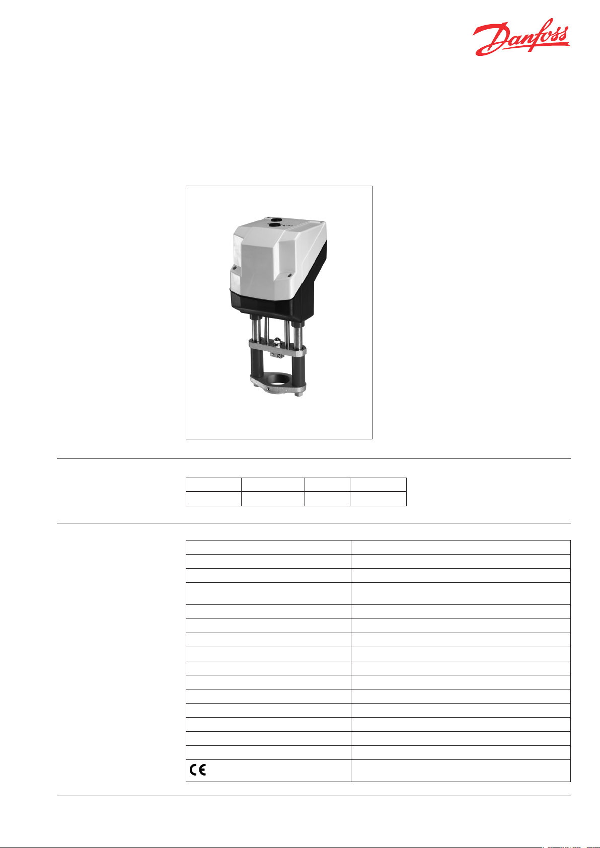
Actuator for modulating control
AME 85QM
Description AME 85QM actuator is used together with large
pressure independent balancing and control
valves type AB-QM DN 200 and DN 250.
Special features:
• position indication
• automatic adaptation of stroke to the valve’s
end position to reduce commissioning time
(self stroking)
• advanced design incorporates load related
“switch off” to ensure that actuators and
valves are not exposed to overload
• manual operation
Main data:
• Nominal voltage:
- 24 VAC, 50 Hz/60 Hz
• Control input signal:
-
0(4)…20 mA
- 0(2) … 10 V
• Force: 5.000 N
• Stroke: 40 mm
• Speed: 8 s/mm
• Max. medium temperature: 200 °C
Ordering
Technical data
Typ e Power supply Speed Code No.
AME 85QM 24 VAC 8 s/mm 082G1453
Power supply 24 VAC, +10 to –15%
Power consumption 12.5 VA
Frequency 50 Hz / 60 Hz
Control input Y 0 … 10 V (2 … 10 V) Ri = 50 Ω,
Output signal X 0 … 10 V (2 to 10 V)
EMC IEC 801/2 - 5
Close of force 5000 N
Max. stroke 40 mm
Speed 8 s/mm
Max. medium temperature 200 °C
Ambient temperature 0 … 55 °C
Storage and transport temperature –40 … +70 °C
Degree of protection IP 54
Protection class II
Weight 9.8 kg
- marking in accordance with standards
0 … 20 mA (4 … 20 mA) Ri = 500 Ω
Low Voltage Directive (LVD) 2006/95/EC: EN 60730-1, EN 60730-2-14
EMC Directive 2004/108/EC: EN 61000-6-2, EN 61000-6 -3
SMT/SI VD.CV.E1.02 © Danfos s 05/2010 1
Page 2
2 VD.CV.E1.02 © Danfos s 05/2010 SMT/SI
Data sheet Actuator for modulating control AME 85QM
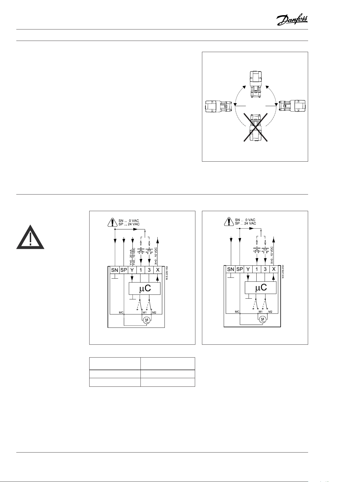
Installation Mechanical
Installation of the valve with the actuator is
allowed in horizontal position or upwards.
Installation downwards is not allowed.
Use the 57 mm castellated nut (supplied) to
fit the actuator to the valve body. While the
actuator is being tted, a 8 mm Allan key can be
used to tighten the pinch screw in the valve body
ring to stop the valve turning.
Allow for necessary clearance for maintenance
purposes.
Electrical
Electrical connections can be accessed by
removing the actuator cover. Two cable gland
entries with thread (M20 x 1.5 and M16 x 1.5) are
prepared for cable glands.
Note: Cable and cable gland used must not
compromise the actuator’s IP rating, and must
ensure the connectors are fully strain relieved.
Please observe local rules and regulations as well.
Wiring
24 Vac only.
Wiring for modulating control Wiring for 3-point control
Note:
If switch SW6 is set to ON than use this wiring.
Wiring length
0 - 50 m 0.75 mm
> 50 m 1.5 mm
Recommended
square of the wiring
2
2
SP 24 V~ ............................................Power supply
SN 0 V ................................................Common
Y 0 to 10 V ......................................Input signal
(2 to 10 V)
0 to 20 mA
(4 to 20 mA)
X 0 to 10 V ......................................Output signal
(2 to 10 V)
Automatic self stroking feature
When power is first applied, the actuator will
automatically adjust to the length of the valve
stroke. Subsequently, the self stroking feature
can be re-initialised by changing position of SW9.
Diagnostic LED
The red diagnostic LED is located on the pcb
under the cover. It provides indication of
three operational states: Actuator Healthy
(Permanently ON), Self Stroking (Flashes once per
second), Error (Flashes 3 times per second - seek
technical assistance).
Page 3
SMT/SI VD.CV.E1.02 © Danfos s 05/2010 3
Data sheet Actuator for modulating control AME 85QM
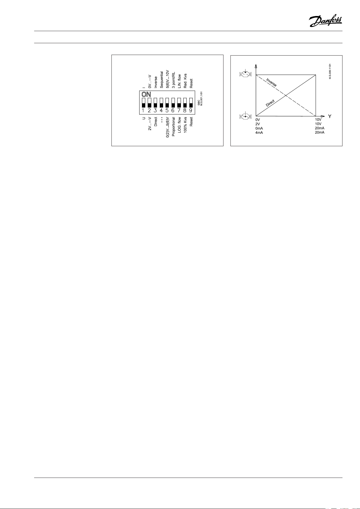
DIP switch setting
The actuator has a function selection DIP switch
under the removable cover. In particular, if SW6
is set to ON, the actuator will perform as
3-point actuator.
The switch provides the following functions:
• SW1: U/I - Input signal type selector:
If set to OFF position, voltage input is selected. If
set to ON position, current input is selected.
• SW2: 0/2 - Input signal range selector:
If set to OFF position, the input signal is in the
range from 2 V to 10 V (voltage input)
or from 4 mA to 20 mA (current input). If set to
ON position, the input signal is in the range from
0 V to 10 V (voltage input) or from 0 mA to 20 mA
(current input).
• SW3: D/I - Direct or inverse acting selector:
If set to OFF position, stem retracts as voltage
increases. If set to ON position, stem extends as
voltage increases.
• SW4: —/Seq - Normal or sequential mode
selector:
If set to OFF position, the actuator is working
in range 0(2)..10V or 0(4)..20mA. If set to ON
position, the actuator is working in sequential
range; 0(2)..5 (6)V or (0(4)..10 (12)mA) or
(5(6)..10V)or (10(12)..20mA).
• SW5: 0..5V/5...10V - Input signal range in
sequential mode:
If set to OFF position, the actuator is working in
sequential range 0(2)..5 (6)V or 0(4)..10 (12)mA.
If set to ON position, the actuator is working in
sequential range; 5(6)..10V or 10(12)..20mA.
•
SW6: Prop./3-pnt - Modulating or 3-point
mode selector:
If set to OFF position, the actuator is working
normally according to control signal. If set to
ON position, the actuator is working as 3-point
actuator.
For this operation please refer to page 2
(wiring for 3-point control).
When DIP switch SW6 is set to ON than all
functions from other DIP switches become
inactive.
• SW7: LOG/LIN - Equal percentage or linear
ow through valve selector1:
If set to OFF position, the ow through valve
is equal percentage. If set to ON position, the
ow through valve is linear according to control
signal.
• SW8: 100% KVS/Reduced KVS
To be set to OFF position.
• SW9: Reset:
Changing this switch position will cause the
actuator to go through a self stroking cycle.
Page 4

4 VD.CV.E1.02 © Danfos s 05/2010 SMT/SI
Data sheet Actuator for modulating control AME 85QM
Commissioning Commissioning / testing feature
Complete the mechanical and electrical
installation and perform the necessary checks
and tests:
The actuator can be driven to the fully open or
closed positions (depending on valve type) by
connecting SN to terminals 1 or 3.
• Isolate control medium. (e.g. self stroking
in a steam application without suitable
mechanical isolation could cause a hazard).
• Apply the power. Note that the actuator will
now perform the self stroking function.
• Apply the appropriate control signal and
check the valve stem direction is correct for
the application.
• Ensure that the actuator drives the valve over
its full stroke, by applying the appropriate
control signal. This action will set the valve
stroke length.
The unit is now fully commissioned.
Manual operation
(1)Remove grommets (2)Push (3)Turn
The manual operation is applied by rotating the
8 mm Allan key (not supplied) to the required
position. Observe the direction of rotation
symbol.
• Disconnect power
• Remove grommets and push the button
• Adjust valve position using an 8 mm Allan key
• Set valve to closed position
• Restore power
Actuator - valve
combination
Note:
Actuator will restore position required by
Y signal.
AME 85QM + AB-QM (DN 200, 250)
Page 5

SMT/SI VD.CV.E1.02 © Danfos s 05/2010 5
Data sheet Actuator for modulating control AME 85QM
Dimensions (mm)
Page 6

6 VD.CV.E1.02 © Danfos s 05/2010 SMT/SI
Data sheet Actuator for modulating control AME 85QM
Page 7

SMT/SI VD.CV.E1.02 © Danfos s 05/2010 7
Data sheet Actuator for modulating control AME 85QM
Page 8

Data sheet Actuator for modulating control AME 85QM
8 VD.CV.E1.02 Prepare d by Danfoss A/S © 05/2010
 Loading...