

Page 1
Operating Guide
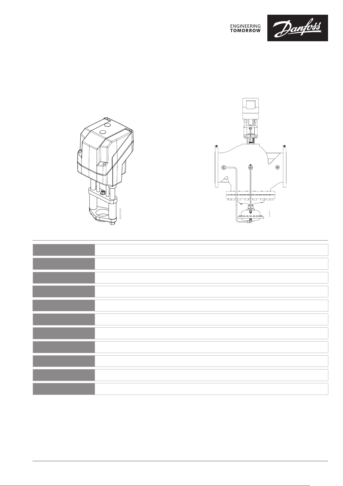
AME 85 QM
AME 85 QM / 73691330
ENGLISH
DEUTSCH
FRANÇAIS
NEDERLANDS
ESPAÑOL
ITALIANO
POLSKI
ČESKY
MAGYAR
中文
РУССКИЙ
AME 85 QM +AB- QM (DN 200, 250)
AME 85 QM www.danfoss.com Page 5
AME 85 QM www.waerme.danfoss.de Seite 6
AME 85 QM www.danfoss.fr Page 7
AME 85 QM www.danfoss.nl Bladzijde 8
AME 85 QM www.danfoss.es Página 9
AME 85 QM www.danfoss.it Pagina 10
AME 85 QM www.heating.danfoss.pl Strona 11
AME 85 QM www.cz.danfoss.com Strana 12
AME 85 QM www.danfoss.com 13. oldal
AME 85 QM www.danfoss.com
AME 85 QM www.danfoss.ru Стр. 15
第 14 页
© Danfoss | 2021.08 AQ00128646944803-010301 | 1
Page 2
AME 85 QM
=
AUTO
❶
❷
MAINTENANCE
FREE
①
5-95 % RH
no condensing
8 mm
=
4 – 6 mm × 1 mm 8 mm HN 10
②
③
②
④
❸
①
①
②
AC 24 V
Connect via safety isolating
transformer.
Proportional 3 point/RL
SN 0 V Neutral
SP 24 VAC Power supply
Y
1
0 V Input
3
0(2)-10 V
0(4) -20 mA
Input
X 0(2) -10 V Output
AQ00128646944803-010301 2 | © Danfoss | 2021.08
Page 3
AME 85 QM
➍
① ②
③ ④ ⑤
⑥
Proportional 3 point/RL
SN
SP
1
24 VAC Input
3
X 0(2 )-10 V DC Output
⑦ ⑧ ⑨
0 V
24 VAC
⑩
Neutral
Power supply
⑬
⑫
© Danfoss | 2021.08 | 3AQ00128646944803-010301
Page 4
AME 85 QM
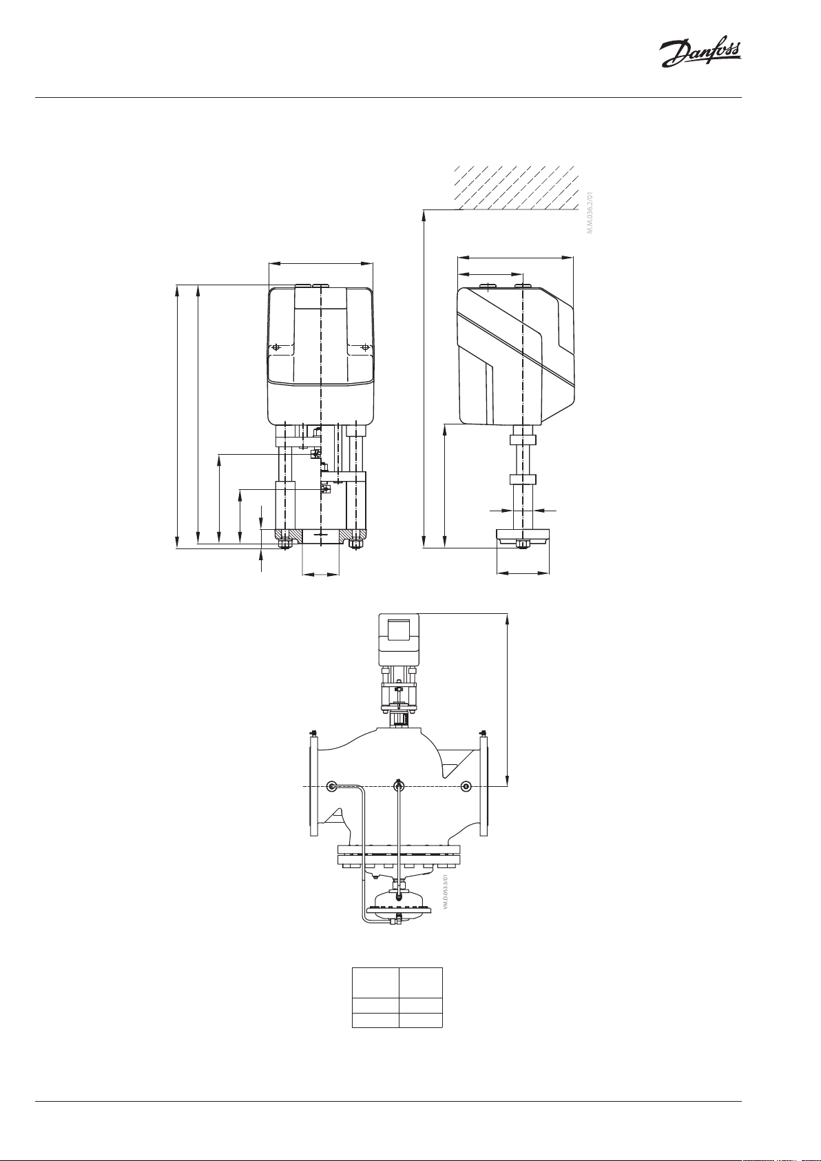
H
(mm)
DN 200
618
DN 250
708
❺
167
412
403
mi n 137
max 85
22
Ø 57
min 530
191,5
183
103
30
82
AME 85 QM +
AB‑QM DN 200, 250
Typ e
H
AQ00128646944803-010301 4 | © Danfoss | 2021.08
Page 5
AME 85 QM
ENGLISH
Safety Note
To avoid injury of persons and
damages to the device, it is absolutely
necessary to read and observe these
instructions carefully.
Necessary assembly, start-up, and maintenance
work must be performed by qualified and
authorized personnel only.
Please comply with the instructions of the
system manufacturer or system operator.
Do not remove the cover befo re the
power supply is fu lly switched off.
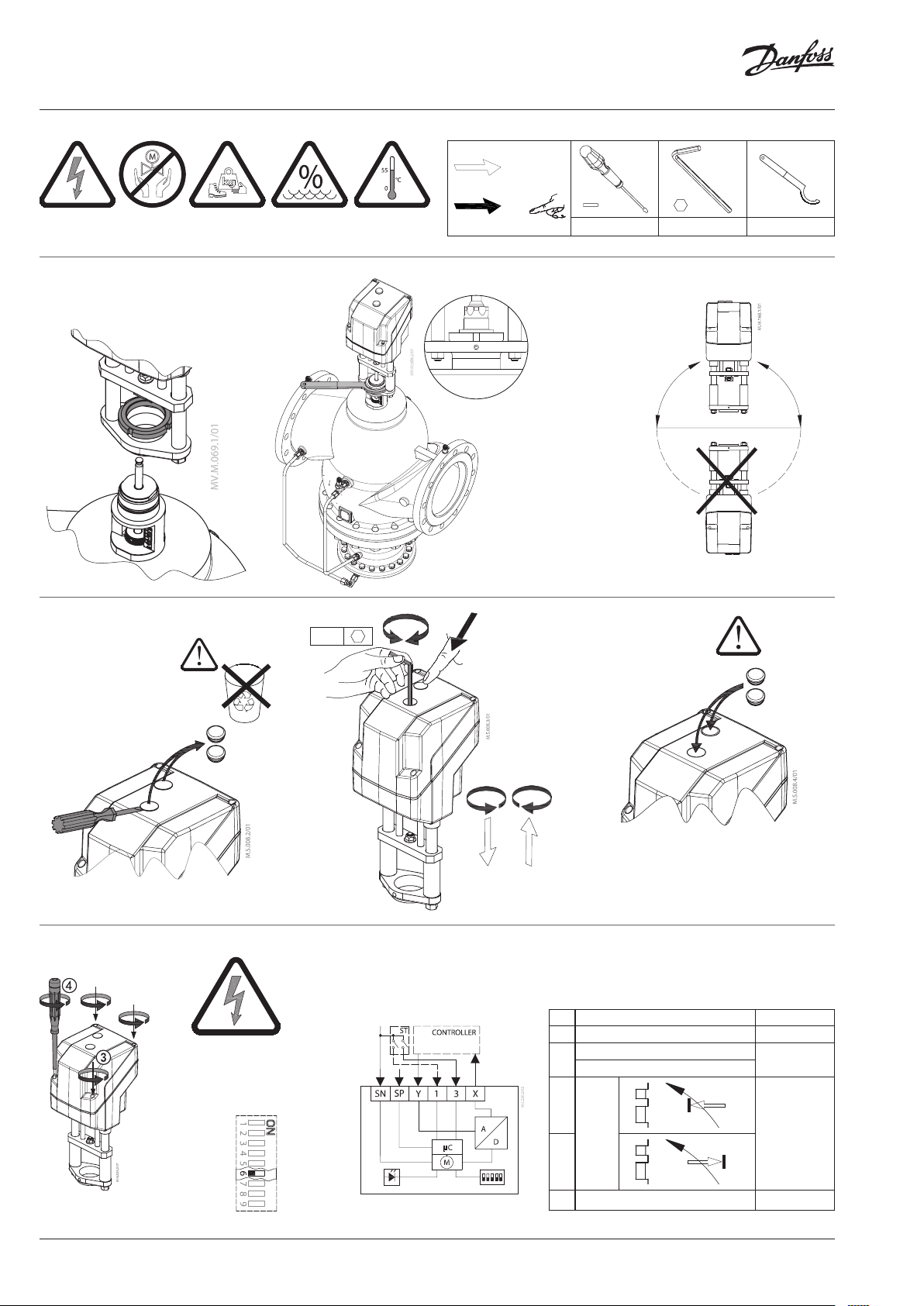
Mounting ❶
Fix the AME 85, AME 86 on the valve ①.
Admissible Installation Positions ②.
Manual override ➋
The manual override is applied by rotating the
8 mm Allen key (not supplied) to the required
position. Observe the direction of rotation
symbol.
Wiring ❸
Do not touch anythi ng on the PCB!
Switch off the power li ne before wire
the actuator! Lethal vo ltage!
Wire the actuator accordin g to the wiring
diagram.
Control signal
Control signal from the controller must be
connected to terminals Y (input signal) and SN
(common) on the AME printed board.
Output signal
Output signal from the terminal X can be used
for indication of the current position. Range
depends on the DIP switch settings.
Supply voltage
Supply voltage (24V~ -15 to +10 %, 50 Hz) must
be connected to the terminals SN and SP.
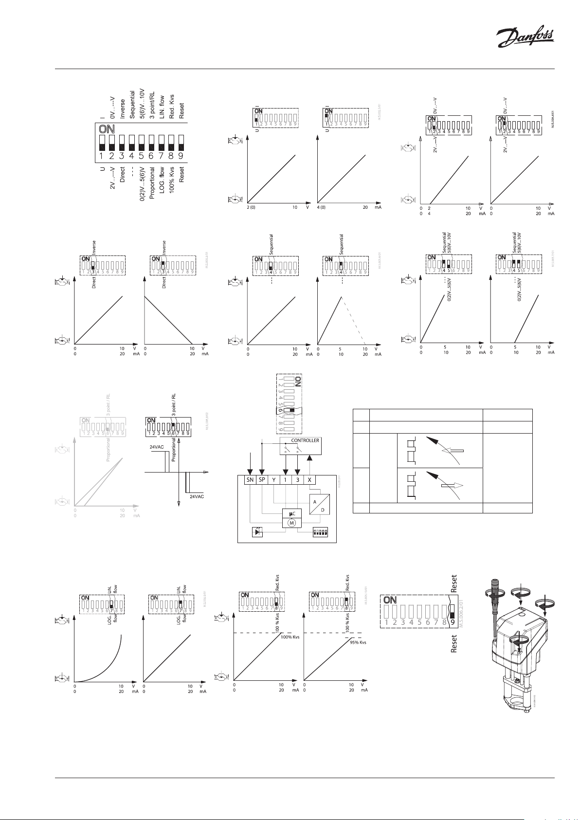
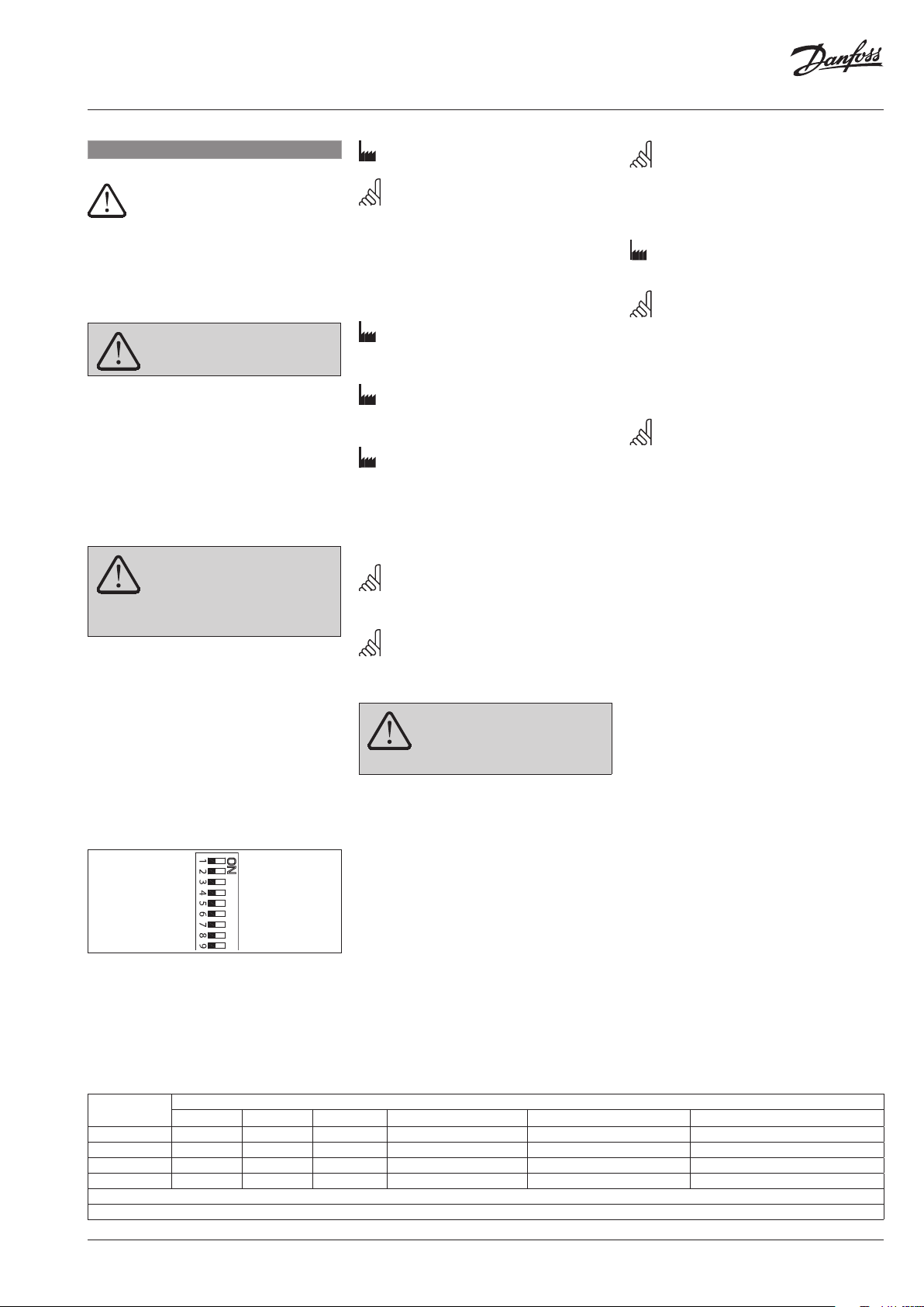
DIP switch settings ➍
U I
2 V_--- V 0 V_- -- V
Direct Inverse
--- Sequential
0(2)_5(6) V 5(6)_10 V
Proportional 3 point/RL
LOG. fl ow LIN. flow
100 % k
VS
Reset Reset
RED. k
VS
Factory settings:
ALL switches are on OFF position! ①
Note: All combinations of DIP switches are
allowed. All func tions that are selected are
added consecutively. There is only one logic
override of functionality i.e. the switch No.6
Proportional/3 point, which sets actuator to
ignore control signal and works as a “simple”
3‑point actuator
SW1: U/I ②
Factor y setting:
Voltage control signal (0‑10 V).
SW2: 2-10 V/0-10 V ③
Factory setting is:
2‑10 V.
SW3: Direct/Inverse ④
Factory setting is:
DIRECT
SW4: ---/Sequential ⑤
Two actuators can be set to work parallel with
one control signal. If the SEQUENTIAL is set than
an actuator responds to split control signal (see
0(2)-5(6) V/5(6)-10 V).
Note: This combination works in combination
with switch No.5: 0(2)‑5(6)V/5(6)‑10 V
SW5: 0(2)-5(6) V/5(6)-10 V ⑥
Note: This function is available if switch No.4:
‑‑‑/Sequential is set.
SW6: Proportional/3 point ⑦
When DIP 6 i s OFF:
actuator needs to p erform self
stroking prior cha nging DIP 6 to ON.
Output signal de pends on DIP 2, 3&5 setting.
Actuator can operate in modulating (DIP 6 to
OFF) or in “simple” 3-point mode, if the 3-point
function is selected (DIP 6 to ON).
Connect power supply on terminals SN and SP
terminals.
DIP 6 factory setting is OFF for modulating
operation.
Actuator’s stem will run to its totally extended
or retracted position by bridging SN signal to
terminals 1 or 3 and will remain in this position
as long as potential is present.
Set DIP 6 to ON for operating actuator in 3 point
mode.
Look carefully wiring diagram as wiring is
different for controllers with triac output (ECL)
in comparison to controllers with relay output.
Note: If 3 point function is selected actuator
does not respond to any control signal on
port Y. It only rises and lowers spindle if power
is supplied on por t 1 or 3
SW7: LOG. flow/LIN. flow ⑧
Factory setting is:
LOG. Flow (characteristic of valve is
unchanged)
Note: If this function is used in combination
with non‑logarithmic valves the characteristic
of motorised valve will be anti‑logarithm of
valve’s characteristic (e.g. valve with linear
characteristic will be transformed to quick
open characteristic).
SW8: 100 % KVS/RED. KVS ⑨
Note: This function works proper only with
logarithmic (equal percentage) valves.
SW9: Reset ⑩
After the actuator has been connected to
power supply, the actuator will start the
self-adjustment procedure. The indicator LED
flashes until self adjustment is finished. The
duration depends on the spindle travel and will
normally last a few minutes. The stroke length
of the valve is stored in the memory after self
adjustment has been completed. To restart
self adjustment, change the position of RESET
switch (switch No.9). If the supply voltage is
switched off or falls below 80 % in more than
0,1 s, the current valve position will be stored
in the memory and all data remain saved in the
memory also after a power supply cut-out.
Function test
The indicator light shows whether the
positioner is in operation or not. Moreover, the
indicator shows the control status and faults.
Constant light
- normal operation
No light
- no operation or no power supply
Intermittent light (1 Hz)
- self adjusting-mode
Intermittent light (3 Hz):
- power supply too low
- insufficient valve stroke (<20 s)
- end-position cannot be reached.
Dimensions ➎
Part Name
Guides X O O O O O
Position indicators X O O O O O
Gears X O O O O O
Bushings X O O O O O
O: Indica tes that this hazar dous substance co ntained in all of the h omogeneous ma terial for this par t is below the limi t requirement in GB /T 26572;
X: Indica tes that this hazar dous substance co ntained in at leas t one of the homoge neous material fo r this part is above t he limit requirem ent in GB/T 26572;
Lead (P b) Mercur y (Hg) Cadmium (Cd) Hexavalent Chromium (Cr(VI)) Polybrominated biphenyls (PBB) Polybrominated diphenyl ethers (PBDE)
Hazardous Substances Table
© Danfoss | 2021.08 | 5AQ00128646944803-010301
Page 6

AME 85 QM
DEUTSCH
Sicherheitshinweise
Montage, Inbetriebnahme und
Wartungsarbeiten dürfen nur von sachkundigen
und autorisierten Personen durchgeführt
werden.
Die Vorgaben des Anlagenherstellers und
Anlagenbetreibers sind zu beachten.
Montage ❶
AME 85, AME 86 am Ventil ansetzen ①.
Zulässige Temperatur ②.
Manuelle Hubverstellung ❷
Die Handverstellung erfolgt durch Verstellen
mit dem 8-mm-Innensechskantschlüssels
(nicht im Lieferumfang enthalten) auf die
gewünschte Position. Die Drehrichtungsanzeige
berücksichtigen.
Elektrischer Anschluß ❸
* 24 V ~ Über Schutztransformator
Steuersignal
Das Steuersignal des Reglers ist an Klemme
Y (Eingangssignal) und Klemme SN
(Sammelklemme) an der AME-Printplatte
anzuschließen.
Ausgangssignal
Das Ausgangssignal von Klemme X kann zur
Anzeige der aktuellen Position benutzt werden.
Der Bereich hängt von der Brücke ab.
Spannungsversorgun3ung (24V~ –15
bis +10 %, 50 Hz) ist an Klemme SN und SP
anzuschließen.
Einstellung der DIP Brücke ❹
Um Verletzungen an Personen und
Schäden am Gerät zu vermeiden, ist
diese Anleitung unbedingt zu
beachten.
Entfernen Sie die Abdeckung nicht,
bevor die Stromversorgung komplett
ausgeschaltet ist.
anschließen (AC 24 V Connect via
safety isolating transformer)
Bitte die Platine nicht direkt berühren!
Trennen Sie das Netz kabel vor der
Spannung!
Schließen Sie den Stellantrieb gemäß dem
Verdrahtungsplan an.
Verdrahtung des Stellantriebs! Tödliche
U I
2 V_---V 0 V_---V
Direkte Sekventiel
--- Proportional
0(2) V_5(6) V 5(6) V_10 V
Omvendt 3-punk t/RL
LOG. fl ow LIN. f low
100 % Kvs Re d. Kvs
Reset Nulstil
Werkseinstellung:
ALLE Schalter sind in der Position OFF! ①
BEMERKUNG: alle Kombinationen von DIP
Schalter sind erlaubt. Gewählte Funktionen
sind hintereinandergelegt. Es gibt nur eine
logische Umsteuerung der Funktionen: Brücke
Nr.6 proportional / 3‑Punkt. Dadurch wird
der Antrieb so umgeschaltet, dass das Signal
ignoriert wird und arbeitet als “üblicher”
3‑Punkt Antrieb.
SW1: U/I ②
Werkseinstellung:
Spannungsregelsignal (0‑10 V).
SW2: 2-10 V/0-10 V ③
Werkseinstellung:
2‑10 V.
SW3: Direct/Inverse ④
Werkseinstellung:
DIRECT
SW4: ---/Sequentiell ⑤
Zwei Antriebe können parallel mit einem
Steuersignal arbeiten. Bei der Einstellung
SEQUENTIAL Antrieb reagiert auf geteilten
Steuersignal (sehe 0(2)-5(6) V/5(6)-10 V).
BEMERKUNG: Diese Kombination
funktioniert mit dem Schalter No.5: 0(2)‑5(6)
V/5( 6)‑10 V.
SW5: 0(2)-5(6) V/5(6)-10 V ⑥
BEMERKUNG: diese Funktion ist wirksam,
wenn der Schalter No.4: ‑ ‑‑ / Sequentiell
eingestellt ist.
SW6: Proportionäl/3-Punkt ⑦
Wenn der DIP‑ 6 ist auf Stellmotor
muss Ventilhub vor dem Ändern de r
DIP 6 auf ON.
Ausgangssignal ist abhän gig von DIP‑2, 3 &5
Einstellung.
Stellmotor kann bei jeglichen arbeiten
modulierend (DIP-6, um AUS) oder in “einfacher”
3-Punkt, wenn die 3-Punkt Funktion ausgewählt
ist (DIP-6, um auf).
Anschließen Spannungsversorgung an den
Klemmen SN und SP Klemmen.
Werkseitig eingestellte DIP 6 auf OFF für den
Betrieb in Stellmotor modulierend Modus.
Stellmotor Antriebsstange ausgeführt
werden soll, der vollkommen erweitert oder
eingefahrener Stellung Audio-Bestandskunden
SN Signal an den Klemmen 1 oder 3 und bleibt
in diesem Position -so lange wie Potenzial
vorhanden ist.
Stellen Sie DIP-Schalter 6 auf EIN für den
Stellmotor in 3 Punkt.
Bitte schauen Sie Schaltplan als Verdrahtung
ist anders für Regler mit Triacausgang (ECL) in
Prachtdecke durch Controller mit Relaisausgang.
BEMERKUNG: Wenn die 3‑Punkt Funktion
gewählt wird, reagiert der Antrieb nicht auf
irgendwelche der Steuersignale Y Klemme.
Der Antrieb bewegt die Motorenspindel nach
oben oder nach unten bei dem Steuersignal
auf Klemme 1 oder 3.
SW7: LOG. flow/LIN. flow ⑧
Werkseinstellung:
LOG. Flow (Ventilcharakteristik bleibt
unverändert).
BEMERKUNG: falls diese Funktion mit dem
nicht logarithmischen Ventil ver wendet wird,
übernimmt der Antrieb die Anti‑Logarithem
der Ventilcharakteristik. (Ventil mit linearer
Kennlinie wird in die Kennlinie umgewandelt).
SW8: 100 % KVS/RED. KVS ⑨
BEMERKUNG: diese Funktion arbeitet richtig
nur mit logarithmischen (gleichprozentigen)
Ventilen.
SW9: Reset ⑩
Nach Einschalten der Stromversorgung startet
der Regelantrieb den Selbstanpassungsvorgang.
Die Leuchtdiode blinkt, bis die Anpassung
abgeschlossen ist. Dies dauert normalerweise
einige Minuten, abhängig von der Distanz
der Spindelbewegung. Die Hublänge
des Ventils wird nach abgeschlossener
Selbstanpassung im Speicher registriert. Der
Selbstanpassungsvorgang kann durch Drücken
der RESET-Taste wiederholt werden (Schalter
No.9). Bei Ausfall der Versorgungsspannung oder beim Absinken auf einen Wert kleiner 80 %
- länger als 0,1 s, wird die aktuelle Ventilposition
im Speicher gespeichert. Alle Daten sind also
auch im Falle einer Stromunterbrechung
gesichert.
Funktionstest
Die Leuchtdiode zeigt den Motorbetrieb, den
Betriebszustand und eventuelle Fehler an.
Dauerlicht
- normaler Betrieb
Kein Licht
- nicht in Betrieb oder keine
Stromversorgung
Blinklicht (1 Hz)
- Selbstanpassungsmodus
Blinklicht (3 Hz)
- Versorgungsspannung zu niedrig
- Ventilhublänge ungenügend (<20 s)
- Endposition nicht erreichbar.
Abmessungen ❺
AQ00128646944803-010301 6 | © Danfoss | 2021.08
Page 7

AME 85 QM
FRANÇAIS
Sécurité
attentivement et de respecter ces instructions.
Le montage, la mise en marche et toute
opération de maintenance doivent être
effectués par un service ou une personne de
qualification.
Suivre les instructions du fabricant du système
ou de son service.
Montage ❶
Fixer l’AME 85, AME 86 sur la vanne ①.
Orientations de montage ②.
Débrayage manuel ➋
Le débrayage manuel est appliqué en faisant
pivoter la clé Allen de 8 mm (non fournie)
dans la position requise. Observez le sens du
symbole de rotation.
Branchement électrique ❸
* 24 V c.a. - Brancher via un transformateur
Signal de commande
Le signal du régulateur doit être branché sur
la borne Y (signal d’entrée) et la borne SN
(commun) sur la carte imprimée de l’AME.
Signal de sortie
Le signal de sortie de la borne X peut servir pour
indiquer la position actuelle. La zone dépend
des réglages du sélecteur de fonction DIP.
Tension d’alimentation
La tension d’alimentation (24V~-15/+10 %, 50
Hz) doit être branchée aux bornes SN et SP.
Réglages du sélecteur de fonction
DIP ❹
Pour éviter des blessures des
personnes et des dégâts au dispositif,
il est absolument nécessaire de lire
Ne pas retirer le capot a vant d’avoir
totalement coupé l’alimentation.
d’isolement de sécurité (AC 24 V Connec t
via safety isolating transformer)
Ne pas toucher la car te de circuit
imprimé !
Couper l’alimentation avant de
raccorder l’actionneur ! Danger de mort !
Raccorder l’actionneur conformément au
schéma de branchement électrique.
U I
2 V_---V 0 V_---V
Direct Inverse
--- Séquentiel
0(2) V_5(6) V 5(6) V_10 V
Proportionnel
Débit LO G. Débit LI N.
100 % Kvs Red . Kvs
Reset Reset
3 points/RL
Réglage d’usine:
TOUTES les commandes sont en position
ARRÊT! ①
REMARQUE: Toutes les combinaisons des
commandes DIP sont possibles.
Toutes les fonctions sélectionnées sont ajoutées
l’une à l’autre. Il y a seulement un pontage logique
des fonctions: commande 6 Proportionnel/ 3
points qui fait le moteur ignorer le signal de
commande et fonctionne comme un »simple«
3‑points moteur.
SW1: U/I ②
Réglage de l’usine:
le signal de commande de tension (0‑10 V).
SW2: 2-10 V/0-10 V ③
Réglage de l’usine:
2‑10 V.
SW3: Direct/Inverse ④
Réglage de l’usine:
DIRECT
SW4: ---/Séquentiel ⑤
Deux moteurs peuvent être réglés de telle
manière qu’ils fonctionnent parallèlement
avec un signal de commande. Si la fonction
SÉQUENTIEL est réglée, le moteur répond au
signal de commande »split« (voir
0(2)-5(6) V/5(6)-10 V).
REMARQUE: Cette combinaison fonctionne
en combinaison avec la commande 5:
0(2)‑5(6)V/5(6)‑10 V.
SW5: 0(2)-5(6) V/5(6)-10 V ⑥
REMARQUE: Cette fonction est disponible, si
la commande 4: ‑‑‑/Séquentiel est réglée.
SW6: Proportionnel/ 3 points ⑦
Lorsque le DIP 6 est SUR Ac tuateur
doit exécuter autoré gulation avant
le DIP en perpétuelle évolution 6 sur
ON.
Signal de sortie d épend du commutateur DIP 2,
3 et 5 Réglage.
Actuateur permet de fonctionner en modulant
(DIP 6 sur OFF) ou dans “simple” 3-points mode,
si la fonction 3 points est sélectionnée (DIP 6
sur ON).
Alimentation pour alimenter les bornes SN et SP
les bornes.
Réglage d’usine DIP 6 sur OFF pour la mise en
œuvre d’Actuateur en mode modulant.
Actuateur tige continue de fonctionner à sa
position rétractée en établissant totalement
étendue ou signal de SN à la borne 1 ou 3
et resteront dans cette positon tant que le
potentiel est présent.
Régler le DIP 6 sur ON pour l’exploitation
Actuateur en mode 3 points.
Schéma de raccordement en tant que regarder
attentivement câblage est différente pour
les régulateurs avec sortie triac (ECL) en
comparaison avec les régulateurs avec sortie
de relais.
REMARQUE: Si la fonction 3 points est
sélectionnée, le moteur ne répond à aucun signal
de commande sur la borne Y. Cette fonction
seulement déplace la broche vers le haut et vers
le bas, s’il y a de l’alimentation en courant sur les
bornes 1 et 3.
SW7: Débit LOG./ débit LIN. ⑧
Réglage de l’usine:
débit LOG. (caractéristique de la vanne ne change
pas).
REMARQUE: Si cette fonction est utilisée
en combinaison avec les vannes non‑
logarithmiques, la caractéristique de la
vanne motorisée sera l’anti‑logarithme
de la caractéristique de la vanne (p.e. une
vanne avec la caractéristique linéaire sera
transformée en caractéristique »rapidement
ouverte«).
SW8: 100 % KVS/RED. KVS ⑨
REMARQUE: Cela ne fonctionne proprement
qu’avec les vannes logarithmiques (même
pourcentage).
SW9: Exploitation ⑩
Une fois alimenté, le moteur commence un
procédé d’auto-réglage. La diode lumineuse
clignote jusqu’à ce que l’auto-réglage soit
términé. Cela dure normalement env. 2 minutes,
suivant le déplacement de la broche. La course
de la vanne est conservée en mémoire à la fin
de l’auto-réglage. Le changement de position
de la commande R. À Z. (commande 9) fera
redémarrer l’auto-réglage. Si l’alimentation est
interrompue – ou chute à une valeur inférieure
à 80 % - pendant plus de 0,1 sec., la position
actuelle de la vanne est mémorisée. Toutes les
données seront donc mémorisées, même en cas
de coupure de courant.
Test de fonction
La diode lumineuse indique que le moteur est
en fonction. Elle indique aussi l’état de marche
et les erreurs éventuelles.
Lumière permanente
- marche normale
Pas de lumière
- fonction arrêtée, pas d’alimentation
Clignotements par intervalles (1Hz)
- mode d’auto-réglage
Clignotement par intervalles (3Hz)
- alimentation en courant trop faible
- course de vanne insuffisante (<20s)
- la fin de course ne peut pas être atteinte.
Dimensions ❺
© Danfoss | 2021.08 | 7AQ00128646944803-010301
Page 8

AME 85 QM
NEDERLANDS
Veiligheid
Om verwondingen van personen en
schade aan het apparaat te voorkomen
dient men deze instructies met
aandacht te lezen.
Montage, inbedrijfstelling en
onderhoudswerkzaamheden mogen alleen
door deskundig en erkend personeel uitgevoerd
worden.
Neem alle instructies betreffende
installatiecomponenten van andere fabrikanten
in acht.
Verwijder de afdek kap niet voordat de
voedingsspanning volledig is
uitgeschakeld.
Montage ❶
Bevestig de servomotor op de afsluiter ①.
Toegestane montage posities ②.
Handbediening ❷
De handbediening gebeurt door de (niet
meegeleverde) inbussleutel van 8 mm in de
juiste positie te draaien.
Bekijk de richting van het rotatiesymbool.
Aansluiting ❸
Gevaarlijke spanning, raak niets aan
op de printplaat. Sch akel de stroom uit
voordat de bedrading van d e
servomotor wordt aangebracht!
Dodelijke spanning!
Sluit de servomoto r aan volgens het
aansluitschema.
* AC 24 V (AC 24 V)
** Verbind via een transformator met
veiligheidsisolatie (Connect via
safety isolating transformer.)
Stuursignaal
Het stuursignaal van de regelaar wordt
aangesloten op klem Y (ingangssignaal) en op
klem SN (gemeenschappelijke nul) van de AME
printplaat.
Uitgangssignaal
Het uitgangssignaal van klem X (t.o.v. klem SN)
kan gebruikt worden als indicatie van de
klepstand. Het bereik hangt af van de instelling
van de DIP schakelaars.
Voedingsspanning
De voedingsspanning (24 V~ -15 tot +10%,
50 Hz) wordt aangesloten op de klemmen SN (nul)
en SP (24Vac).
Dip-schakelaarinstellingen ➍
U I
2 V_---V 0 V_---V
Direct . Inver se
--- Sequential (volgorde)
0(2)_5(6) V 5(6)_10 V
Proportional 3 point/RL
LOG. fl ow LIN. flow
100 % k
VS
Reset Reset
RED. k
VS
Fabrieksinstellingen:
alle schakelaars staan in de OFF (uit)‑
positie.①
NB: Alle combinaties van DIP‑instellingen zijn
toegestaan. Alle gekozen functies worden bij
elkaar opgeteld. Er is echter één uitzondering
Schakelaar 6 Propor tional / 3 point, welke de
motor instelt als “simpele” 3‑punts servomotor.
SW1: U/I ②
Fabrieksinstelling:
0‑10 V stuursignaal
SW2: 2V … 10 / 0V … 10 ③
De fabrieksinstelling is:
2 … 10V.
SW3: Direct/Omgekeerd ④
De fabrieksinstelling is:
Direct
SW4: ---/Sequential ⑤
Twee servomotoren kunnen naar hetzelfde
signaal “luisteren”. Als Sequential is ingesteld
reageert de motor op een gedeeld signaal.
NB: Deze instelling werkt samen met
schakelaar 5: 0(2) V … 5(6 V) / 6(6) V … 10 V
SW5: 0(2) V … 5(6 V)/6(6) V … 10 V ⑥
NB: Deze functie is geldig als schakelaar 4 op
Sequential staat.
SW6: Proportioneel/3-punts ⑦
De servomotor werkt als een simpele 3-punts
motor als de 3punts functie is ingesteld.
Voedingsspanning wordt aangesloten op de
klemmen SN en SP. Op
24 Vac voor “omlaag”
de klemmen 1 en 3 wordt
en “omhoog” aangesloten.
Uitgangssignaal X geeft de werkelijke stand aan.
NB: in de 3-puntsfunctie reageert de
servo motor niet op signalen via klem Y. De
spindel beweegt alleen bij spanning op klem
1 of klem 3.
SW7: LOG flow/LIN flow ⑧
Fabrieksinstelling:
LOG. Flow (afsluiter‑karakteristiek
ongewijzigd)
NB: De grote AB‑QM‑afsluiter heeft een
lineaire karakteristiek.. In de stand LIN
flow blijft de karakteristiek lineair. In de
stand LOG flow wordt de karakteristiek
van de servomotor dusdanig aangepast
dat de servomotor en de afsluiter
tezamen als afsluiter werken met een
LOG‑karakteristiek.
SW8: 100% KVS/RED. KVS ⑨
In te stellen in de stand OFF.
SW9: Reset ⑩
Nadat de servomotor is aangesloten op de
voedingsspanning begint de automatische
afstelprocedure. De indicatie LED knippert tot
de afstelling is beëindigd. De tijdsduur is
afhankelijk van de kleplift en bedraagt
gewoonlijk enkele minuten. De slag van de
klep wordt in het geheugen opgeslagen. Om
de afstelprocedure opnieuw te starten dient
de stand van RESET veranderd te worden.
Wanneer de voedings-spanning wordt
uitgeschakeld of langer dan 0,1s onder 80%
daalt, wordt de momentele klepstand in het
geheugen opgeslagen en blijven alle
gegevens bewaard, ook na het uitschakelen
van de voeding.
Functietest
De LED indicator toont het motorbedrijf,
bedrijfstoestand en eventuele fouten.
De LED indicator toont het motorbedrijf,
bedrijfstoestand en eventuele fouten.
Continue aan
- normaal bedrijf
Continu uit
- geen bedrijf of geen voedingsspanning
Knipperend (1 Hz)
- automatische afstelprocedure
Knipperend (3 Hz):
- voedingsspanning te laag
- onvoldoende klepslag (,20 s)
- eindpositie onbereikbaar.
Afmetingen ❺
AQ00128646944803-010301 8 | © Danfoss | 2021.08
Page 9

AME 85 QM
ESPAÑOL
Nota de seguridad
instrucciones.
Las operaciones de montaje, puesta en marcha
y mantenimiento deben ser realizadas
únicamente por personal cualificado y
autorizado.
Por favor, respete las instrucciones del
fabricante u operador del sistema.
Montaje ❶
Montaje del AME 85, 86 en la válvula ①.
Posiciones permitidas de instalación ②.
Cancelación manual ❷
La cancelación manual se lleva a cabo girando
la llave Allen de 8 mm (no suministrada) hasta la
posición precisa. Preste atención a los símbolos;
proporcionan información acerca del sentido
de giro.
Cableado ❸
* AC 24 V conexión a través de un transformador
Seńal de control
La seńal de control proveniente del regulador
deberá ser conectada al terminal Y (seńal de
entrada) y al terminal SN (común) en el circuito
impreso del AME.
Seńal de salida
La seńal de salida del terminal X puede usarse
para indicar la posición actual. El rango
dependerá de la configuración del interruptor
DI P.
Tensión de alimentación
La tensión de alimentación (24V~-15/+10 %, 50
Hz) tiene que ser conectada a los terminales SN
y SP.
Las configuarciones del interruptor
DIP ❹
A fin de evitar lesiones personales o
daños en el dispositivo, es
absolutamente necesario leer y
respetar estrictamente estas
No retire la cubier ta antes de haber
desconectado el suministro eléctrico
por completo.
aislante de seguridad (AC 24 V Connect
via safety isolating transformer)
¡
No toque nada en la pl aca de circuito
impreso!
¡Desacti ve la línea de suministro eléc trico
¡Tensión letal!
Conecte el ac tuador de acuerdo con el esq uema de
cableado.
antes de conectar el actuador!
U I
2 V_---V 0 V_---V
Directo Secuencial
--- Proporcional
0(2) V_5(6) V 5(6) V_10 V
Inverso 3 punt os R / L
Flujo LOG . Flujo LIN.
100 % Kvs Red. Kvs
Restablecimiento Restablecimiento
Ajuste de fábrica:
Todos los interruptores tienen que estar en la
posición OFF! ①
IMPORTANTE: Todas las combinaciones de
los interruptores están permitidas. Todas las
funciones seleccionadas serán añadidas una
a la otra. Solamente hay una sobreposición de
las funciones: el interruptor No.6 Proporcional
/ 3 vías que hace que el actuador ignore la
señal y funcione como un “sencillo” actuador
de 3 vías.
SW1: U/I ②
Ajuste de fábrica:
señal de control de tensión (0 ‑10 V).
SW2: 2-10 V/0-10 V ③
Ajuste de fábrica:
2‑10 V.
SW3: Directo/Inverso ④
Ajuste de fábrica:
DIRECT
SW4: ---/Secuencial ⑤
Se pueden ajustar dos acuadores
simultaneamenete que respondan a la misma
señal de control a la vez.
Al elegir SEQUENTIAL el actuador responderá
a la señal de control dividida (vease 0(2)-5(6)
V/5(6)-10 V).
Nota: Esta combinación funciona en
combinación con el interruptor No.5:
0(2)‑ 5(6) V/5(6)‑10 V).
SW5: 0(2)-5(6) V/5(6)-10 V ⑥
Nota: Esta función es posible al elegir el
interruptor No.4:‑‑‑/ Secuencial.
SW6: Proporcional/3 vías ⑦
Cuando los interruptores DI P 6 es de
actuador debe realizar ajuste
automático de la longitu d de carrera
antes del conmutador DIP 6 en l a posición ON.
Señal de salida de pende de los interruptores DI P
2, 3 &5 Ajuste.
Actuador puede funcionar en modulante (DIP
6 a OFF) o en modo “simple” 3-puntos, si la
función se selecciona 3 puntos (DIP 6 a).
Conectar la corriente de alimentación SN y SP.
terminales de los terminales.
Ajuste de fábrica los interruptores DIP 6 en la
posición OFF para el funcionamiento actuador
modulante en modo.
Actuador vástago es totalmente extendida
o se ejecutará hasta su posición retraída,
señal de transición SN a los terminales 1 o 3
y permanecerá en tal tomografía mientras
potencial está presente.
Ajuste los interruptores DIP 6 en
funcionamiento actuador de 3 puntos modo.
Observe atentamente diagrama de
conexionado como cableado es diferente
para los controladores con salida triac (ECL) en
comparación a los controladores con salida de
relé.
Importante: Al elegir la función de 3 vías,
el actuador no responerá a ninguna de las
señales de control en el puerto Y. El vástago
se moverá hacia arriba o abajo si hay
alimentación en el puerto 1 ó 3.
SW7: LOG.flow/LIN.flow ⑧
(LOG.flujo /LIN.flujo)
Ajuste de fábrica:
LOG flow (característica de la válvula no
cambiada)
Imporatante: Al usar esta función con las
válvulas no logarítmicas, la característica de
la válvula motorizada será el antilogaritmo
de la característica de la válvula (por ejemplo
la válvula con la característica linear será
transformada en al caracteristica de apertura
rápida).
SW8: 100 % KVS/RED. KVS ⑨
Nota: Esta función funciona correctamente
solamente con las válvulas logarítmicas (de
flijo igual porcentage).
SW9: Funcionamiento ⑩
Después de suministrar corriente de
alimentación al actuador, éste inicia un proceso
de auto ajuste. El diodo LED parpadea hasta
que el proceso de auto ajuste haya llegado a
término. Este proceso dura normalmente un
par de minutos dependiendo del recorrido
del vástago. El recorrido de la válvula es
almaceneado en la memoria después de
terminado el auto ajuste. Para empezar de
nuevo el auto ajuste pulsar el interruptor
RESET (interruptor No.9). Si se corta la tensión
de alimentación o en caso de que ésta caiga
por debajo de 80 % durante más de un 0,1 s, la
posición actual de la válvula será guardada en
la memoria. De esta manera, todos los datos
quedarán guardados en la memoria, incluso en
caso de corte de corriente.
Test de funcionamiento
El diodo luminoso indica si el motor está
funcionando. Además indica el estado de
funcionamiento y fallos eventuales.
Luce constantemente
- funcionamineto normal
No luce
- no está en marcha, no hay alimentación
Luce intermitentemente a intervalos (1 Hz)
- estado de auto ajuste
Luce intermitentemente a intervalos (3 Hz)
- corriente de alimentación demasioado baja
- recorrido de la válvula insuficinete
(<20 s)
- el recorrido máximo no puede ser
alcanzado.
Dimensiones ❺
© Danfoss | 2021.08 | 9AQ00128646944803-010301
Page 10

AME 85 QM
ITALIANO
Attenzione
Per evitare danni alle persone e
all’apparecchio, è assolutamente
attentamente queste istruzioni.
Montaggio, avviamento e manutenzione
devono essere eseguiti solo da personale
autorizzato e qualificato.
Seguire sempre le istruzioni del costruttore o
dell’assistenza.
Montaggio ❶
Fissare l’AME 85 QM sulla valvola ①.
Posizioni d’installazione consentite ②.
Esclusione manuale ❷
Per agire in modo manuale, ruotare la chiave
esagonale da 8 mm (non fornita) sulla posizione
richiesta. Osservare la direzione di rotazione del
simbolo.
Collegamento elettrico ❸
* 24 VAC: Collegare tramite trasformatore di
Segnale di comando
Il segnale di comando deve essere collegato
ai morsetti Y (ingresso segnale) e SN (comune)
serigrafati sulla scheda dell’AME.
Segnale di uscita
Il segnale di uscita dal morsetto X può essere
utilizzato per indicare la posizione della valvola.
Il campo dipende dalla configurazione del DIP
switch.
Alimentazione
L’alimentazione (24 V ~ -15/+10 %, 50 Hz) deve
essere collegata ai morsetti SN e SP.
Impostazioni dei DIP switch ❹
necessario leggere e osservare
Non rimuovere il cope rchio prima di
aver completamente scollegato
l’alimentazione elettrica.
isolamento di sicurezza.
(Connect via safety isolating transformer.)
Non toccare i componenti del PCB!
Scollegare dalla rete di alimentazione
prima di effettuare i collegamenti
elettrici sull’attuatore! Tensione mortale!
Collegare l’attuatore secondo lo schema
elettrico.
U I
2 V_--- V 0 V_- -- V
Diretto Invers o
---
0(2)_5(6) V 5(6)_10 V
Proporzionale 3 punti/RL
Portata LOG. Portata LIN.
100 % k
VS
Resettaggio Resettaggio
Sequenziale
RED. k
VS
Impostazioni di fabbrica:
Tutti gli switch sono in posizione OFF! ①
Nota: Tutte le combinazioni dei DIP switch
sono consentite. Tutte le funzioni selezionate
sono aggiunte in sequenza. C’è soltanto una
sovrapposizione logica delle funzioni, ad es.
lo switch N°6 Proporzionale/3 punti, che fa
ignorare all’attuatore il segnale di comando
e lo fa funzionare come un “semplice” motore
a 3 punti.
SW1: U/I ②
Impostazione di fabbrica:
Segnale di comando di tensione (0‑10 V).
SW2: 2-10 V/0-10 V ③
Impostazione di fabbrica:
2‑10 V.
SW3: Diretto/Inverso ④
Impostazione di fabbrica:
DIRETTO
SW4: ---/Sequenziale ⑤
Due attuatori possono essere configurati per
far sì che funzionino in parallelo con lo stesso
segnale di comando. Se è settata la funzione
SEQUENZIALE, allora l’attuatore risponde al
segnale di comando “split” (vedi 0(2)-5(6) V/5(6)10 V).
NOTA: Questa combinazione va associata allo
switch No 5: 0(2)‑5(6)V/5(6)‑10 V
SW5: 0(2)-5(6) V/5(6)-10 V ⑥
NOTA: Questa funzione è disponibile
se lo switch No 4: ‑‑‑ /Sequenziale viene
selezionato.
SW6: Proporzionale/3 punti ⑦
Se viene selezionata la funzione 3punti, allora
l’attuatore può funzionarecome “semplice”
attuatore a 3 punti. L’alimentazione elettrica
deve essere collegata ai morsetti SN e SP. Il
segnale di comando 24 V CA è collegato per
l’apertura e la chiusura dell’attuatore ai morsetti
1 o3. Il segnale di ritorno X corrisponde alla
posizione corretta.
Nota: Se la funzione a 3 punti è selezionata,
l’attuatore non risponde al segnale di
comando sul morset toY. Alza e abbassa
l’alberino solo quando l’alimentazione è
presente sui morsetti 1 o 3.
SW7: Portata LOG./Portata LIN. ⑧
Impostazioni di fabbrica:
Portata LOG. (le caratteristiche della valvola
rimangono immutate)
NOTA: La maggior parte delle valvole
Danfoss dotate di attuatore hanno una curva
caratteristica portata/posizione logaritmica
(equi-percentuale). Impostando lo switch su
portata LIN. la caratteristica della valvola può
essere modificata. Questa combinazione di
attuatore e valvola corrisponde ad una valvola
con curva caratteristica LINEARE.
SW8: 100 % KVS/RED. KVS ⑨
NOTA: Questa funzione può essere
correttamente utilizzata solo con valvole
logaritmiche (equi‑percentuali).
SW9: Ripristino ⑩
Dopo essere stato alimentato, l’attuatore inizia
una procedura di auto-determinazione della
corsa. Il LED lampeggia fino a quando l’autoregolazione è terminata. Questa operazione
dura normalmente pochi minuti a seconda della
corsa. La corsa della valvola viene memorizzata
alla fine di questa processo. Per ripetere la
procedura di auto-determinazione occorre
modificare la posizione del RIPRISTINO (switch
N° 9). Se la tensione viene a mancare o si
abbassa ad un valore inferiore all’80 % per più
di 0,1 s, la posizione attuale della valvola viene
memorizzata. Anche tutti i dati verranno salvati
in caso di interruzione della corrente.
Test di funzionamento
L’indicatore luminoso indica se l’attuatore è
in funzione o meno. Indica inoltre lo stato di
funzionamento o di avaria.
Luce costante
- funzionalità normale
Nessuna luce
- nessun funzionamento né alimentazione
Luce intermittente (1 Hz):
- modalità di autoregolazione
Luce intermittente (3 Hz):
- alimentazione troppo bassa
- corsa insufficiente della valvola (<20 s)
- il fine corsa non può essere raggiunto.
Dimensioni ❺
AQ00128646944803-010301 10 | © Danfoss | 2021.08
Page 11

AME 85 QM
POLSKI
Warunki bezpieczeństwa
Aby uniknąć obrażeń u ludzi oraz
uszkodzenia
zapoznać się
z tymi informacjami i przestrzegać ich.
Niezbędne prace związane z montażem,
uruchomieniem i konserwacją mogą być
wykonywane wyłącznie przez autoryzowany
wykwalifikowany personel.
Prosimy stosować się do instrukcji producenta
lub operatora układu.
Nie zdejmować pok rywy p rzed
całkowitym
Montaż ❶
Zamontować siłownik AME 85, AME 86 na
zaworze ①.
Dopuszczalne pozycje montażu ②.
Sterowanie ręczne ❷
Ręczne sterowanie jest realizowane przez
obrót 8 mm klucza imbusowego (nie jest na
wyposażeniu) do odpowiedniego położenia.
Należy zwrócić uwagę na symbole opisujące
kierunek obrotu.
Okablowanie ❸
* 24 V AC Podłączać za pośrednictwem
separującego transformatora
bezpieczeńst wa (AC 24 V Connect
via safety isolating transformer)
Wersja na 230 V~
Nie wolno nic zego dotykać na pł ytce
jest pod napięciem! Zagrożenie życia!
Podłącze nia przewodów wykon ać zgodnie ze
schematem podłączeń elektrycznych.
Sygnał sterujący
Sygnał sterujący ze sterownika musi być
podłączony do wyprowadzeń Y (sygnał
wejściowy) oraz SN (masa) na płytce drukowanej
siłownika AME.
Sygnał wyjściowy
Sygnał wyjściowy z wyprowadzenia X może być
użyty do wskazania bieżącej pozycji. Zakres
zależy od ustawień przełącznika DIP.
Napięcie zasilania
Napięcie zasilania (24V~ -15 do +10 %, 50Hz)
musi być podłączone do wyprowadzeń SN i SP.
Ustawienia przełącznika DIP ❹
obwodu drukowanego, gdy urządzenie
0(2) V_5(6) V 5(6) V_10 V
Proporcjonalny 3-punktowy/RL
sprzętu, należy koniecznie
odłączeniem zasilania.
U I
2 V_---V 0 V_---V
Zgodnie Odwrotnie
--- Sequential
LOG. fl ow LIN . flow
100 % Kvs Red. Kv s
Reset Reset
i
Wszystkie wybierane funkcje są sumowane.
Istnieje tylko jedno logiczne ominięcie
funkcjonalności: przełącznik nr 6 Proportional
/3 point (Proporcjonalny/3‑punktowy),
który powoduje, że siłownik ignoruje sygnał
sterujący i działa jako prosty 3‑punktow y
siłownik.
SW1: U/I ②
Ustawienie fabryczne:
sterowanie sygnałem napięciowym (0..10 V).
SW2: 2-10 V/0-10 V ③
Ustawienie fabryczne:
2‑10 V.
SW3: Direct/Inverse ④
Ustawienie fabryczne:
DIRECT
SW4:---/Sequential ⑤
Dwa siłowniki mogą być sterowane równolegle
jednym sygnałem sterującym. Jeśli wybrana jest
opcja SEQUENTIAL, siłownik reaguje na dzielony
sygnał sterujący (patrz 0(2)-5(6) V/5(6)-10 V).
UWAGA: To ustawienie działa w połączeniu z
przełącznikiem nr 5: 0(2)‑5(6) V/5(6)‑10 V
SW5: 0(2)-5(6) V/5(6)-10 V ⑥
UWAGA: Ta funkcja jest dostępna, gdy
ustawiony jest przełącznik nr 4: ‑‑ ‑ /
Sequential.
SW6: Proportional/3 point ⑦
Gdy przełąc znik DIP 6 jest NA
Siłownik musi w ykonywać
samodostrajania przed zmianą
ustawień przełąc znika DIP 6 na ON (WŁ. ).
Sygnał wyjściow y zależy od DIP 2, 3 &5 nas tawa.
Siłownik może pracować w modulujący (DIP 6
do WYŁĄCZONY) lub w “proste” 3-punktowego,
po wybraniu opcji 3-point (DIP 6 ON).
Podłączyć napięcie zasilania na zaciskach SN i
SP zacisków.
Fabrycznie ustawione na OFF DIP 6 do obsługi
Siłownik w trybie modulujący.
Siłownik jest całkowicie wysunięty trzpień
będzie pracować w jego trakcie wsuwania
trzpienia lub przez możliwość przemierzania
SN sygnał do zacisków 1 i 3 i pozostanie w
tym pozytronowa tak długo, jak jest obecny
potencjał.
Ustawić Siłownik DIP 6 do pracy w trybie
3-punktowy.
Przyjrzyj się uważnie jak połączenia elektryczne
schemat połączeń elektrycznych jest różne w
zależności od regulatorów z wyjścia triakowe
(ECL) w porównanie do regulatorów z wyjście
przekaźnika.
UWAGA: Jeśli wybrano opcję 3‑point,
siłownik nie reaguje na jakikolwiek sygnał
sterujący na w yprowadzeniuY. Siłownik
będzie podnosił i opuszczał wrzeciono, jeśli
na wyprowadzenia 1 i 3 zostanie podane
napięcie.
SW7: LOG. flow/LIN. flow ⑧
Ustawienie fabryczne:
LOG. Flow (niezmieniona charakterystyka
zaworu)
UWAGA: Jeśli ta funkcja jest uż ywana w
połączeniu z zaworami nielogarytmicznymi,
charakterystyka zaworu napędzanego będzie
antylogarytmem charakterystyki zaworu
(np. zawór liniowy przekształci się w zawór
szybkiego otwarcia).
SW8: 100 % KVS/RED. KVS ⑨
UWAGA: Ta funkcja działa prawidłowo
wyłącznie z zaworami logar ytmicznymi
(stałoprocentowymi).
SW9: Reset ⑩
Po podłączeniu siłownika do zasilania
rozpoczyna się procedura samoregulacji.
Dioda LED błyska do momentu zakończenia
tego procedury. Trwa to zazwyczaj parę
minut w zależności od skoku wrzeciona. Po
zakończonym procesie samoregulacji wartość
skoku zaworu jest zachowana w pamięci.
Zmiana pozycji przełącznika RESET (przełącznik
nr 6) ponownie wyzwala proces samoregulacji.
Jeżeli napięcie zasilające zostanie odcięte lub
przez okres ponad 0,1 sekundy spadnie poniżej
80 %, to aktualna pozycja zaworu jest chowana
w pamięci; zapewnia to, zachowana zachowanie
wszystkich danych - również w przypadku
przerw w zasilaniu.
Test działania
Dioda świetlna wskazuje, czy silnik jest aktywny
czy też nie. Co więcej, dioda LED wskazuje
też status sterowania i błędy.Dioda świetlna
wskazuje, czy silnik jest aktywny czy też nie.
Co więcej, dioda LED wskazuje też status
sterowania i błędy.
Stałe świecenie
- normalna pracaBrak świecenia
- brak działania lub zasilania
Miganie z częstotliwością 1Hz
- tryb samoregulacji
Miganie z częstotliwością 3Hz
- zbyt niskie napięcie zasilania
- niedostateczny skok zaworu (<20 s)
- nie można osiągnąć położenia
krańcowego.
Wymiary ❺
Ustawienia fabryczne:
wszystkie przełączniki są w położeniu OFF! ①
UWAGA: Dozwolone są wszystkie
kombinacje przełąc zników DIP.
© Danfoss | 2021.08 | 11AQ00128646944803-010301
Page 12

AME 85 QM
ČESKY
Bezpečnostní pokyny
Abyste předešli zranění osob a
poškození zařízení, před montáží a
přečíst tyto pokyny a bezpečnostní instrukce.
Nedemontujte servopohony s funkcí
bezpečnostní pružiny! Při nesprávné manipulaci
hrozí nebezpečí zranění nebo usmrcení!
Servopohon je těžký. Manipulujte s ním opatrně,
abyste předešli zranění osob nebo poškození
produktu.
Montáž ❶
Upevněte AME 85 QM na ventil ①.
Přípustná instalační poloha ②.
Ruční ovládání ❷
Ruční ovládání se provádí otočením
imbusového klíče 8 mm (není přiložen) do
požadované polohy. Všímejte si směru značky
otáčení.
Zapojení ❸
* Připojte 24 V AC prostřednictvím
Řídicí signál
Řídicí signál z řídicí jednotky musí být připojen
ke svorkám Y (vstupní signál) a SN (společný
vodič) na desce tištěných spojů AME.
Výstupní signál
Výstupní signál ze svorky X lze použít pro
indikaci aktuální polohy. Rozsah závisí na
nastavení přepínačů DIP.
Napájecí napětí
Napájecí napětí (24 V~ -15 až +10 %, 50 Hz) musí
být připojeno ke svorkám SN a SP.
Nastavení DIP spínače ❹
uváděním zařízení do provozu si musíte
Nesundávejte kryt, dokud není
napájen í zcela vypnuto.
bezpečnostního izolačního transformátoru
(AC 24 V Connect via safety
isolating transformer)
Nedotýkejte se ni čeho na elektronice
pohonu!
Před zapojováním ser vopohonu
vypněte elektrické vedení! Přítomnost napětí
nebezpečného životu!
Servopohon zapojte podle schématu zapojení.
U I
2 V_--- V 0 V_- -- V
Přímý Inverzní
--- Sekvenční
0(2)_5(6) V 5(6)_10 V
Proporcionální
Průtok LO G Pr ůtok LIN
100 % k
VS
Resetování Resetování
3bodový/RL
RED. k
VS
Tovární nastavení:
VŠECHNY spínače jsou nastaveny do V YPNUTÉ
polohy! ①
Poznámka: Všechny kombinace přepínačů
DIP jsou povoleny. Všechny funkce, k teré jsou
vybrány, jsou přidány po sobě. Existuje pouze
jedno logické potlačení funkcí, tj. spínač č.6 Volba
modulačního nebo třípolohového režimu, který
nastavuje servopohon tak, aby ignoroval řídicí
signál a plnil funkci „jednoduchého“ 3bodového
servopohonu.
SW1: U/I ②
Tovární nastavení:
Napěťový reg ulační signál (0‑10 V).
SW2: 2-10 V/0-10 V ③
Tovární nastavení:
2‑10 V.
SW3: Přímý/Inverzní ④
Tovární nastavení:
PŘÍMÝ
SW4: ---/Sekvenční ⑤
Dva servopohony lze nastavit tak, aby
pracovaly paralelně s jedním řídicím signálem.
Pokud je nastaven do polohy ON, pracuje
servopohon v sekvenčním rozsahu:0(2)...5(6)
V nebo 0(4)...10(12)mA nebo 6(6)...10V nebo 10
(12)....20mA.
Poznámka: Tato kombinace pracuje spolu se
spínačem č.5: 0(2)‑5(6) V/5(6)‑10 V
SW5: 0(2)-5(6) V/5(6)-10 V ⑥
Poznámka: Tato funkce je použitelná pouze s
nastaveným spínačem č. 4: ‑‑‑/Sekvenční.
SW6: Modulační nebo třípolohový režim ⑦
Servopohon může pracovat jako „jednoduchý“
3bodový servopohon, pokud je navolená
3bodová funkce. Napájení by mělo být
připojeno k portům SN a SP. Na portu 1 nebo
3 je připojen signál 24 V AC pro zvedání nebo
spouštění servopohonu. Zpětný signál X
signalizuje správnou polohu.
Poznámka: Pokud navolíte 3bodovu funkci,
servopohon nereaguje na žádný řídicí signál
na portu Y. Pouze zvedne a spustí vřeteno,
pokud je napájení přivedeno na port 1 nebo 3.
SW7: Průtok LOG/Průtok LIN; volba
rovnoprocentí nebo linearní
charakteristiky ⑧
Tovární nastavení:
LOG. Průtok (charakteristika ventilu je
nezměněna)
Poznámka: Velké ventily AB‑QM mají lineární
charakteristiku. S nastavením spínače do
polohy Průtok LIN zůstávají charak teristiky
lineární . Pokud nastavíte spínač do polohy
Průtok LOG, průtok ventilem je nastaven na
rovnoprocentí charakteristiku.
SW8: 100 % KVS/RED. KVS ⑨
Poznámka: Tato funkce funguje správně
pouze slogaritmickými (rovnoprocentními)
vent ily.
SW9: Resetování ⑩
Po zapojení ke zdroji napájecího napětí se
servopohon začne automaticky nastavovat.
LED kontrolka bude během tohoto nastavování
blikat. Doba nastavování závisí na délce dráhy
vřetena a obvykle trvá několik minut. Velikost
dráhy zdvihu je po dokončení nastavování
uložena do paměti. Chcete-li nastavování
zopakovat, tak stačí změnit polohu spínače
RESET (spínač č. 1). Jestliže dojde k výpadku
dodávky elektrické energie nebo poklesne-li
napětí pod 80 % nominální hodnoty na dobu
delší než 0,1 sec, zaznamená se do paměti
aktuální poloha kuželky ventilu. Tyto hodnoty
zůstanou v paměti uloženy i v tom případě, kdy
bude servopohon odpojen od zdroje elektrické
energie.
Funkční test
Kontrolka zobrazuje, zda je polohovač funkční,
nebo nikoliv. Kromě toho kontrolka zobrazuje
kontrolní stavy a poruchy.
Trvale svítí
- normální funkce
Nesvítí
- žádná funkce nebo bez napájení
Svítí přerušovaně (1 Hz)
- režim vlastního nastavení
Svítí přerušovaně (3 Hz):
- napájení je příliš nízké
- nedostatečný zdvih ventilu (<20 s)
- nelze dosáhnout koncové polohy.
Rozměry ❺
AQ00128646944803-010301 12 | © Danfoss | 2021.08
Page 13

AME 85 QM
MAGYAR
Biztonsági megjegyzések:
Az itt szereplő utasítások gondos
elolvasása és betartása feltétlenül
fontos a személyi sérülések és
berendezés károsodások elkerülésére.
A szükséges szerelési, beállítási és karbantartási
munkákat kizárólag szakképzett és megbízott
személyzet végezheti el.
Kérjük, tartsa be a rendszer gyártójának és
üzemeltetőjének rendelkezéseit!
Ne távolítsa el a fedele t a
tápfeszültség teljes lekapcsolása előtt.
Beépítés ❶
Szerelje fel az AME 85 QM egységet
aszelepre ①.
Lehetséges beépítési helyzetek ②.
Kézi működtetés ❷
A kézi működtetést egy 8 mm-es belső nyílású
kulcsnak (nem tartozék) a kívánt helyzetbe
történő elfordításával végezhetjük el. Ügyeljen a
forgásirány jelzésre.
Bekötés ❸
* AC 24 V Kapcsolás a biztonsági
szigetelőtranszformátoron keresztül.
(AC 24 V Connect via safety
isolating transformer)
Ne érintsen meg semm it a PCB‑n!
Kapcsolja ki a tápellátást mielőtt
beköti az állítóművet! Életveszélyes
feszültség! Csatlakoztassa az állítóművet az
elektromos bekötési rajz szerint.
Vezérlőjel
A szabályozóról érkező vezérlőjelet az Y
(bemenőjel) és az SN (közös) csatlakozókra kell
csatlakoztatni az AME nyomtatott áramköri
lapon.
Kimeneti jel
Az X csatlakozóról érkező kimeneti jel
használható az aktuális pozíció kijelzésére. A
tartomány a DIP kapcsolók beállításától függ.
Tápfeszültség
A tápfeszültséget (24 V~ -15-től +10%-ig, 50 Hz)
az SN és az SP csatlakozókhoz kell csatlakoztatni.
DIP kapcsolók beállításai ❹
U I
2 V_--- V 0 V_- -- V
Egyenes Fordított
--- Szekvenciális
0(2)_5(6) V 5(6)_10 V
Arányos 3-pontos/RL
LOG. Térfogatáram LIN. térfogatáram
100 % k
VS
Visszaállítás Visszaállítás
RED. k
VS
Gyári beállítások:
MINDEGYIK kapcsoló OFF (KI) állásban
van! ①
MEGJEGYZÉS: A DIP kapcsolók helyzeteinek
minden kombinációja megengedett.
Minden kiválasztott funkció egymás után
hozzáadódik a korábbiakhoz. Csak egy
esetben bírálja felül a funkcionalitásokat
a logika, amikor a 6‑os számú kapcsoló a
Proportional (Arányos) / 3ponton van, amely
úgy állítja be a szelepmozgatót, hogy az ne
reagáljon a vezérlőjelre, és „egyszerű” három‑
pont vezérlésű állítóműként üzemeljen.
SW1: U/I ②
Gyári beállítás:
feszültség vezérlőjel (0‑10 V).
SW2: 2-10 V/0-10 V ③
A gyári beállítás:
2‑10 V.
SW3: Egyenes/Fordított ④
A gyári beállítás:
EGYENES
SW4: ---/Szekvenciális ⑤
Két szelepmozgató párhuzamos működésre
állítható egy vezérlőjellel működtetve.
SZEKVENCIÁLISRA állított helyzetben a
szelepmozgató úgy reagál, hogy felosztja a
vezérlőjelet (lásd a 0(2)-5(6) V/5(6)-10 V).
MEGJEGYZÉS: Ez a kombináció az 5. számú
mikrokapcsolóval együtt működik:
0(2)‑5(6)V/5(6)‑10 V
SW5: 0(2)-5(6) V/5(6)-10 V ⑥
MEGJEGYZÉS: Ez a funkció akkor áll
rendelkezésre, ha a 4 számú mikrokapcsoló:
‑‑‑/SZEKVENCIÁLIS helyzetben van.
SW6: Arányos/3-pontos ⑦
A szelepmozgató működhet „egyszerű” hárompont vezérlésű állítóműként, ha a három-pont
funkció van kiválasztva. A tápfeszültsége
az SN és az SP pontokra kell csatlakoztatni.
Az 1-es vagy a 3-as ponthoz a 24 VAC jel
csatlakozik a szelepmozgató fel, vagy le irányú
mozgatásához. A visszatérő X jel jelzi a helyes
pozíciót.
Megjegyzés: ha a három‑pont funkció
van kiválasztva, a szelepmozgató nem
reagál semmilyen, az Y porton megjelenő
vezérlőjelre. Csak akkor emeli fel, vagy engedi
le az orsót, ha feszültséget kap az 1‑es vagy a
3‑as ponton.
SW7: LOG. Térfogatáram/LIN.
térfogatáram ⑧
Gyári beállítás:
LOG. Vízátfolyás (a szelep jelleggörbéje
változatlan)
MEGJEGYZÉS: A nagy AB‑ QM szelepek
jelleggörbéje lineáris. Ha a kapcsoló LIN
pozícióban áll, a jelleggörbe lineáris
marad. Ha a kapcsoló LOG pozícióban áll, a
szelepmozgató vízátfolyási jelleggörbéje úgy
módosul, hogy a szelepmozgató és a szelep
LOG jelleggörbéjű szelepként működik együtt.
SW8: 100 % KVS/RED. KVS ⑨
MEGJEGYZÉS: Ez a funkció csak logaritmikus
(egyenszázalékos) szelepeknél működik
megfelelően.
SW9: Visszaállítás ⑩
Az egység tápfeszültségre kapcsolása után, a
szelepmozgató elkezdi az önbeállítást.
Az LED az önbeállítás befejezéséig villog. Az
időtartam az orsómozgás nagyságától függ, és
normál esetben a folyamat eltart néhány percig.
Az önbeállítás befejezésekor a szeleplöket
hossza eltárolásra kerül a memóriában. Az
önbeállítás újrakezdéséhez változtassa meg
a RESET mikrokapcsoló (1. kapcsoló) állását.
Ha a tápfeszültség lekapcsolódik, vagy 0,1
másodpercnél tovább 80 % alá esik, akkor
az aktuális szeleppozíció elmentésre kerül a
memóriában. Energiaellátás kimaradásakor az
Működés vizsgálat
A jelzőfény mutatja, hogy a pozicionáló
működik-e vagy sem. Továbbá, a kijelző mutatja
a szabályozó státuszát és hibáit.
Állandó fényjelzés
- normál működés
Nincs fényjelzés
- nem működik, vagy nincs energiaellátás
Szakaszosan világító fény (1 Hz)
- önbeállító mód
Szakaszosan világító fény (3 Hz):
- tápfeszültség túl alacsony
- elégtelen szelep löket (<20 mp)
- véghelyzet nem elérhető.
Méretek ❺
© Danfoss | 2021.08 | 13AQ00128646944803-010301
Page 14

AME 85 QM
有害物质含量表
汞
镉
六价铬
多溴联苯
多溴二苯 醚
说明书
位置指示器
齿轮
XOOOO
O
轴套管
XOOOO
O
表示该有害物质在该部件 所有均质材料中的含量 均在GB/T 2657 2规定的限量要求以下。
表示该有害物质至少在该部件的某一均质材料中的含量超出
规定的限 量要求。
不要碰触电路板上的任何元件!
请按接线图接线
当
是在驱动器需要执行行程
定。
中文
安全注意事项
行。
请遵循系统制造商或系统操作人员的说明。
安装❶
将AME85,AME86驱动器安装到阀体上 ①
允许的安装朝向 ②
手动操控 ❷
转动 8 毫米 Alley 钥匙(未提供)至指定位置,
即转为手动操控。注意观察旋转图标的方向。
接线 ❸
* 24 V 交流通过安全隔离变压器连接
控制信号
从控制器来的控制信号接到AME 的Y端(输入
信号)和SN端(公共端)。
阀位反馈
阀位反馈信号从X 端输出,SN为公共端
电源电压
电源电压(24V -15 % 到+10 % ,50Hz )连接
到端子SN和SP
DIP 拨动开关的设定 ❹
为避免发生人身和设备事故,请仔细
阅读本手册。
安装、调试、维修必须由专业人员进
切 勿 在 完 全 切 断 电 源 之 前 ,揭 开
保护盖。
(AC 24 V Connect via safety isolating
transformer)
接 线 前 请 先 断 开 电 源 !致 命 的 电
压!
U I
2 V_---V 0 V_---V
正向 反向动作
---
0(2) V_5(6) V 5(6) V_10 V
比例控制 三点控制 /RL
LOG. fl ow LIN. flow
100 % k
VS
Reset Reset
顺序动作
RED. k
VS
SW1: U/I ②
出厂设定:
电压控制信号
SW2: 2-10 V/0-10 V ③
出厂设定:
2‑ ‑10 V.
SW3: 正向/反向动作 ④
出厂设定:
正向
SW4: -- -/顺序动作 ⑤
两个驱动器可共用一个控制
信 号 并 联 工 作 。选 择 顺 序 动
作功能后控制信号将被分割
(0(2)-5(6)V/5(6)-10 V)。
注意:此项功能与拨动开关第 5 位配合使
用。
0(2)V‑5(6V)/5(6)V‑10 V。
SW5: 0(2) V-5(6) V/5(6)-10 V ⑥
注意:此项功能当拨动开关第 4 位设为顺
序动作时有效。
SW6: 比例控制/三点控制 ⑦
DIP 6
自检之前更改 DIP 6为" ON "。
输出信号取决于 DIP 2、3和5设
驱 动 器 可 以 运 行 的 调 制( DIP 6为 ”关 闭 ”)或
在”简单的”三点”模式中,如果三点功能(
DIP 6为” ON “)。
连接电源 端子上 SP 和 SN 端子接线端连接。
原厂设置 DIP 6为 OFF 来运行驱动器在调制模
式。
驱动器阀杆它仍会运行完全扩展或缩回位置的
衔接 SN 信号端子1或3,将 一 直 保 持 这 种 正 电 子
只要潜力。
设置 DIP 6为 On 用于操作驱动器在3点模式。
仔细观察电路接线图为接线不同控制器带有
双 向 可 控 硅 输 出( ECL )在 對照 控制器与继电
器输出。
出厂设定:
对数特性
注意:如果驱动器设定为线形而阀体特性
不是对数特性,则组合后的特性可解为快
开特性。
SW8: 100 %KVS 降低/KVS ⑨
选择降低KVS功能后阀门的KVS 值可降为比
它小一号阀门的KVS值与它本身KVS值之间的
中间值。
如:阀门本身KVS值为16,比它小一号阀门的
KVS值为10,则降低以后的KVS值为13。
注意:此项功能仅对对数特性的阀门有
效。
SW9: 复位 ⑩
驱动器第一次通电后将自动进行行程自检,自
检时 LED 指示灯闪烁直到自检结束。
自检的时间根据行程大小和速度快慢各不相
同,大致需几分钟时间。自检结束后行程信息
被记录到存储器中。将拨动开关的第 9位拨到
复位位置也可启动自检进程。电源断电或电压
降低于 80 % 的时间超过 0,1 秒 ,所 有 的 当 前 数
据被保存到存储器中。
功能测试功能测试
LED 指示灯可提供当前状态和故障指示:
持续亮
-正常工作
不亮
-没有任何操作或无电源电
压
闪烁(1Hz)
-自检中
闪烁(3Hz)
-电源电压过低
-行程不对(<20s)
-不能到达末端位置
尺寸 ❺
出厂设定:
所有位都在 OFF 位 置 。①
注意:允许对 DIP 拨动开关进行任意组合。
所有选定的功能将依次添加。 只有一种功
能逻辑操控,即拨动开关第 6 位比例控制/
三点控制,它将把驱动器设为不理会控制
注 意: 注 意: 选择三点控制以后驱动器不对 Y 端
子的控制信号作出反应。
SW7: 对数流量特性/线性流量特性 ⑧
几乎所有丹佛斯阀门的流量特性都是对数特性
的。如果驱动器设定为线性,则驱动器的工作
特性与阀体配合后可得出线性的特性。
信 号 ,而 是 作 为 “简单的”三点驱动器使用。
部件名称
O:
X:
铅 (Pb)
X O O O O O
X O O O O O
(Hg)
(Cd)
GB/T 26572
(Cr( VI))
(PBB)
(PBDE)
AQ00128646944803-010301 14 | © Danfoss | 2021.08
Page 15

AME 85 QM
РУССКИЙ
Техника безопасности
Во избежание получения травм или
повреждений устройства обязательно
прочитайте настоящую инструкцию и
тщательно ее соблюдайте.
Все необходи мые работы по сборке, вводу
действие и техническому обслу живанию
оборудования должны выполняться только
квалифицированным персоналом, имеющим
соответс твующее разрешение.
Следуйте указаниям производителя системы или
оператора системы.
Не снимайте крышку до то го, как
питание будет полностью
отключено.
Установка❶
Закрепить электропривод AME 85, AME86 на
клапане ①.
Монтажные положения регулятора ②.
Ручное позиционирование ❷
Ручное позиционирование производится с
помощью 8-мм шестигранного торцевого ключа (в
комплек т поставки не входит) путем его поворота
до нужного положения. Соблюдайте указанное на
изображении направление вращения.
Схема электрических
соединений ❸
* 24 В переменного тока
Подключать через безопасный
разделительный трансформатор.
(AC 24 V Connect via safety
isolating transformer)
Не прикасаться к открытым
контактам!
монтажом проводки электропривода!
Опасное для жизни напряжение!
Смонтируйте про водку привода согласно
электрической схеме.
Управляющий сигнал
Управляющий сигнал с регулятора подается на
клеммы Y (входной сигнал) и SN (ноль) платы AME.
Выходной сигнал
Выходной сигнал с клеммы Х может быть
использован для индикации текущего положения.
Диапазон зависит от нас троек переключателя DIP.
Напряжение питания
Напряжение питания (24 В переменного тока от –15
до +10 %, 50 Гц) подается на клеммы SN и SP.
Настройки переключателя DIP ❹
Отключать линию питания перед
U I
2 V_---V 0 V_---V
Прямо обратно
---
0(2) V_5(6) V 5(6) V_10 V
Аналоговый 3 импульсный/R L
Логарифмическая Линейная харак теристика
100 % Kvs Red. Kv s
Сброс Сброс
последовательно
в
Заводские установки:
ВСЕ переключатели находятся в
положении OFF (выключено). ①
ПРИМЕЧАНИЕ: Приемлемы все
комбинации переключателей DIP. Все
выбранные функции добавляются
друг к другу. Существует только одно
логическое перерегулирование функций:
переключатель № 6 – (аналоговый/
импульсный) настраивать исполни‑
тельный механизм таким образом
аналоговый, что он игнорирует
управляющий сигнал и работает как
импульсный исполнительный механизм.
SW1: U/I (напряжение/ток) ②
Заводская установка:
управляющий сигнал напряжения
(0 ‑ 10 B).
SW2: 2-10B/0-10 B ③
Заводская установка:
2‑10 B.
SW3: Прямо/обратно ④
Заводская установка:
ПРЯМО.
SW4: ---/последовательно ⑤
Существует возможнос ть установить два
исполнительных механизма так, что они работают
параллельно, с одним управляющим сигналом.
Если настроена функция ПОС ЛЕДОВАТЕЛЬНО,
то исполнительный механизм реагирует на
управляющий сигнал «сплит»
(см. 0(2)-5(6) В/5(6) -10 В).
ПРИМЕЧАНИЕ: Данная схема работает в
комбинации с переключателем № 5: 0(2)‑
5(6) В/5(6)‑10 В.
SW5: 0(2)-5(6) В/5(6)-10 В ⑥
ПРИМЕЧАНИЕ: Данная функция
имеет место лишь в случае, если
настроен переключатель № 4: ‑‑‑/
последовательно.
SW6: Аналоговый / импульсный ⑦
Если DIP‑ 6 ‑ это на привод,
исполнительный механизм
необходимо выполнить выход ной
сигнал зависит от DIP‑2, 3 5 настройка.а
перед изменением DIP 6.
привод, исполнительный механизм могу т работать
в модулирующий (6 в положение OFF (выкл.))
или в “простой” 3-позиционное режим, если
3-позиционное функция выбирается (6).
сеть питания подключается на клеммы SN и SP.
клеммам.
Заводские настройки перек лючателя DIP 6 в
положение OFF (выкл.) для управления привод,
исполнительный механизм в модулирующий
режим.
привод, исполнительный механизм клапана
будет работать в его совершенно прод ление или
отведенное положение, связывая их SN сигнал к
клеммам 1 или 3 и будет оставаться в этом позиция
до тех пор, пока потенциал.
Установите переключатель DIP 6 на привод,
исполнительный механизм для работы в 3 режима
точки.
Внимательно посмотрите электрическая схема как
монтаж проводки для регуляторов с симисторные
выходы (ECL) в сравнение для регуляторов с
релейный выход.
ПРИМЕЧАНИЕ: В случае, если выбрана
импульсная функция, исполнительный
механизм не реагирует ни на какой
аналоговый управляющий сигнал на входе
Y. Исполнительный механизм поднимает
и опускает шток только в случае, если
электропитание подаетс я на вход 1
или 3.
SW7: Логарифмическая/Линейная
характеристика ⑧
Заводская установка:
(Логарифмическая) характеристика
регулирования клапана не меняется.
ПРИМЕЧАНИЕ: В случае применения
данной функции в комбинации с
“нелогарифмическими” клапанами,
характеристика моторного клапана
будет являться антилогарифмом
характеристики клапана (например,
клапан с линейной характеристикой
трансформируется в характеристик у
быстрого открывания).
SW8: 100 % KVS/REDKVS ⑨
ПРИМЕЧАНИЕ: Данная функция
работает корректно только в случае
применения клапанов с логарифмической
(равнопоцентной) характеристикой
регулирования.
© Danfoss | 2021.08 | 15AQ00128646944803-010301
Page 16

AME 85 QM
SW9: Reset (Сброс) ⑩
После подачи тока на исполнительный механизм
последний начинает процесс автоподстройки.
Об этом свидетельствует мигание светодиода,
которое продолжается до окончания процесса
автоподстройки. Продолжительность процесса
обычно составляет несколько минут, в
зависимости от перемещения штока. Величина
хода клапана после окончания автоподстройки
регистрируется в запоминающем устройстве.
Процесс автоподстройки возобновляется нажатием
на кнопку сброса «RESET» (перек лючатель № 9).
При сбросе напряжения питания или при его
падении более чем на 80 % в течение более 0,1
с, текущее положение клапана регис трируется
в запоминающем устройстве. Таким образом ,
вся информация сохраняется в запоминающем
устройстве, в том числе в случаях сбоя напряжения
питания.
Функциональный тест
Световой диод наряду с индикацией
задействования привода производит также
индикацию рабочего состояния и возможных
ошибок.
Постоянное свечение
- обычное рабочее состояние эксплуатации
Отсутствие свечения
- выключение, напряжение отключено.
Прерывистое свечение (1 Гц):
- режим автоподстройки
Прерывистое свечение (3 Гц):
- электропитание слишком мало
- недостаточная величина времени хода
клапана (<20 с)
- невозможность входа в исходное положение.
Габаритные ❺
ІМПОРТЕР:
UA: ТОВ з ІІ «Данфосс ТОВ», вул. Вікентія Хвойки, 15/15/6, м. Київ, 04080, Україна
73691330 / AQ00128646944803-01030116 | © Danfoss | DCS-S/SI | 2021.08
 Loading...