

Page 1
Data sheet
AME 658 SU/ SD – with safety function
Motorized actuators for AB-QM™ valves
Description
The actuators AME 658 series are designed to
regulate the AB-QM valve in applications involving
heating and chiller applications.
The available options include input signals of
modulating or 3-point oating and actuators that
have a safety function in either spring open or
close during a power failure.
Main data:
• 24V AC/DC powered actuators
• Control input signal: modulating or 3-point
• Selectable actuator speed
• Max. medium temperature: 392 °F (200 °C )
Features:
• Manual operation either mechanical and/or
electrical
• Output signal
• Visible LED feedback operation
• Selectable stem travel speed
• Inverse functionality
• Self calibration of acuator stem travel
• Integrated external switch
• Characteristic optimization
• Stem travel limitation
• Pulse or continuous output signal
• Voltage or current input signal Y
• Voltage or current output signal X
• External reset button
• Auto detection of Y signal
• X and Y galvanic insulation
• Thermic and overload protection
Ordering
Actuators
Code No. Typ e Power Supply Input Signal Safety Func. w/o power
082G3450 AME 658
082G3448 AME 658 Spring down
VDHUR122 © Danfoss 10/2015
24V
3-point oating
or Modulating
Spring up
1
Page 2
Data sheet AME 658 SU/SD Motorized actuators for use with AB-QM™
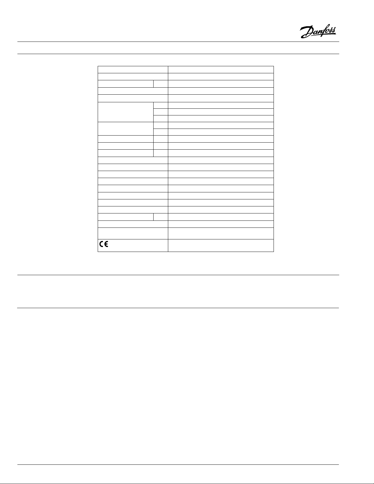
Technical data
Actuator type AME 658 SU/SD
Power supply 24 V AC or DC; +10 … –15% @ 50 or 60 Hz
Power consumption VA 19.2
Control input 3-point oating or Modulating
Position in power failure Open or close
VDC 0-10 (2-10) [Ri = 40 kΩ]
Control input Y
Control output X
Closing force N 2000
Max. travel distance mm 50
Speed (selectable) s/mm 4 or 6
Max. medium temperature 392 °F (200 °C) (350 with extension piece for VFGS)
Ambient temperature 32 to 131 °F (0 to 55 °C)
Storage and transport temperature -40 to 158 °F (-40 to 70 °C) (storing for 3 days)
Humidity 5-95%
Protection class II
Grade of enclosure IP 54 (NEMA 13)
Weight 18.9 lb (8.6 kg)
Safety function Yes
Spring return runtime sec 120
Manual operation Electrical and mechanical
Power failure response
- marking in accordance with
the standards
mA 0-20 (4-20) [Ri = 500 Ω]
3-point (wiring auto-detection)
VDC 0-10 (2-10) [Ri = 10 kΩ]
mA 0-20 (4-20) [Ri = 510 Ω]
SU - Valve is open
SD- Valve is closed
Low Voltage Directive 20 06/95/EEC
EMC Directive 2004/108/EEC
Commissioning
2
The actuator must be dismantled and the elements sorted into various material groups before disposal.Disposal
Complete the mechanical and electrical installation (see instructions) and perform the necessary
checks and tests:
- Power the actuator
- Set the appropriate control signal and check
that the valve stem direction is correct for the
application.
The unit is now fully commissioned.
VDHUR122 © Danfoss 10/2015
Page 3
Data sheet AME 658 SU/SD Motorized actuators for use with AB-QM™
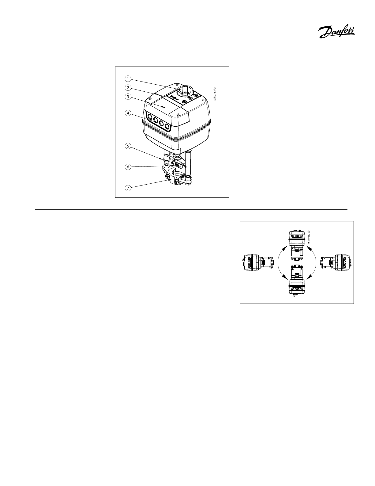
Design
Installation Mechanical
The allowable orientation of the actuator can
be installed in all positions. Allow for necessary
clearance for maintainance and for the mounting
of the actuator to the valve. A M8 socket to mount
the actuator to the valve and a 4mm Allen key to
link the valve stem to the actuator.
1. Manual operation knob
2. Function buttons
3. Panel cover
4. Removable gland support
5. Position indication ring
6. Stem connector
7. Valve connector
Electrical
Electrical connections can be accessed by
removing the service cover. Four cable entries
are available (Two M16 x 1.5 and two M20 x 1.5)
Note in order to maintain the enclosure IP rating,
appropriate electrical nuts must be used.
VDHUR122 © Danfoss 10/2015
3
Page 4

Data sheet AME 658 SU/SD Motorized actuators for use with AB-QM™
Wiring
AME 658
Do not touch anything on the PCB!
Do not remove the ser vice cover
before the power supply is fully
switched o.
Max. allowed current output on
terminals 4 and 5 is 4 A .
AME 658 wired as 3-point oating
AME 658
SN 0 V Neutral
SP 24VA C/DC Power suppl y
4, 5 SP(AC)
GND 0 V Neutral
Y
X
Controller
SP
0(2 )-10 V
0(4) -20 mA
0(2 )-10 V
0(4) -20 mA
Controller
4
Powered
contact output
5
Input
Output
SN 0 V Neutral
1 24V AC/DC Input
3 24V AC/DC Input
1
4, 5 SP(AC)
4
5
3
Powered
contac t
output
AME 655
4
VDHUR122 © Danfoss 10/2015
Page 5

S4
S5
Data sheet AME 658 SU/SD Motorized actuators for use with AB-QM™
DIP switch setting
AME 658
DIP1: FAST/SLOW – Speed selection
- Speed of actuator travel: 3 (4) or 6 s/mm
DIP2: DIR/INV – Direct or inverse acting
selector (Fig. 2):
- Direction of the actuator movement based input
signal:
- Opens on increase of input signal
- Closes on increase of input signal
DIP3: 2-10V/0-10V – Input/output
- Selection of available input signal range. Signal
range selector sets input (Y) and ouput (X) signal.
- 0-10VDC / 0-20 mA
- 2-10VDC / 4-20 mA
DIP4: LIN/MDF – Characteristic modication
function (Fig. 3):
- Determines the charactersitic of the actuator
as either a linear or logarithmic (MDF selection).
Under MDF the characteristic curve can be ne
tuned by the setting of the potentiometer CM.
DIP5: 100%/95% – Stem travel limitation:
- Selectable full travel (100%) or limited to 95%
stem travel.
DIP6: C/P – Output signal mode selector
(Fig. 4.):
- Reaction of terminal 4 & 5 based upon input
signal. Under selection C potentiometers S4 & S5
can be adjusted.
- C: activates with modulating signal
- P: activates with 3-point oating signal
Fig. 1
Fig. 2
Q
Y
DIP7: Uy/Iy –Input signal type selector:
- Selection between voltage or current input signal
DIP8: Ux/Ix –Output signal type selector:
- Selection between voltage or current output
signal
CM CM CM
Fig. 3
Fig. 4
VDHUR122 © Danfoss 10/2015
5
Page 6

Data sheet AME 658 SU/SD Motorized actuators for use with AB-QM™
LED signalling / actuator
operating modes
LED operating mode indicator
The two LED’s located on the actuator cover
provides three dierent color feedback (green/
yellow/red). Based upon the color and if they ash,
will indicate dierent operating situations.
RESET button
The external RESET button is located on the top
cover of the actuator next to LED indicators.
Pressing this button once will enter or exit the
Stand-By mode. For the AME series of actuators
holding the button for 5 secs will initiate the
calibration mode.
Operating modes
• Stand-By mode
The actuator stops in current position and
does not react to the control signal. In this
mode the actuator can be manual operated
via mechanical handle or control buttons.
To exit Stand-By mode the RESET button is
pressed again.
• Calibration mode
The actuator will enter this mode when it
is powered for the rst time or if the Reset
Button is pressed down for 5 secs. During
calibration the actuator will determine the
full travel of the valve. When calibration is
completed the actuator will be in normal
operation responding to the control signal.
LED indication, AME 658
LED Flashing Constantly Lit
Calibration mode, opening the valve Receiving signal, opening valve
GREEN
Calibration mode, closing the valve Receiving signal, closing valve
Awaiting control signal Actuator has reached full open
YELLOW
RED
DARK No power to actuator / No control signal
Error in actuator operation Stand-by mode
Manual operation Mechanical and electrical operation are
not allowed to be used at the same time!
Actuators AME 658 can be manually positioned
when in Stand-By mode or when there is no power
supply (mechanically).
Actuator has reached full close
6
VDHUR122 © Danfoss 10/2015
Page 7

Data sheet AME 658 SU/SD Motorized actuators for use with AB-QM™
Manual operation,
continued
B
A
A
B
Electrical manual operation
Actuators AME 658 have two buttons on the top
of the housing that are used for electrical manual
positioning (up or down) if the actuator is in Stand-By
mode. First press the RESET button until the actuator
goes to Stand-By mode (red LEDs are lit). By pressing
Mechanical manual operation
Actuators AME 658 have a manual operation knob
on the top of the housing which enables hand
positioning of the actuator.
Prior to the use of the mechanical knob there
should be no power to the actuator.
the upper button
by pressing the lower button
pushed down.
the stem will be lifted and
the stem will be
Dimensions
7.5 i n
(191 mm)
14.5 in (369 mm)
13.9 in (353 mm)
Danfoss can accept no responsibilit y for possible errors in printed materials and reserves the right to alter its products without notice.
All trademarks in this material are proper ty of the respective companies. Danfoss and Danfoss logotype are trademarks of Danfoss A /S. All rights reser ved.
Danfoss
Toronto, ON
Tel.: 866-375-4822, Fax: 416-352-5981
www.na.heating.danfoss.com
Min. 17.7 in (450 mm)
7.3 in
(186 mm)
Danfoss
Baltimore, MD
Tel.: 443-512-0266, Fax: 443-512-0270
www.na.heating.danfoss.com
VDHUR122 © Danfoss 10/2015
7
 Loading...