

Installation Guide
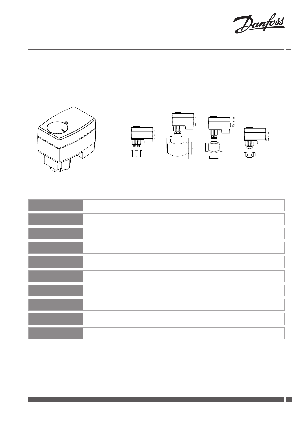
AME 13 SU
AME 13 SU + AME 13 SU + AME 13 SU + AME 13 SU +
VM 2 (DN 15-25) VB 2 (DN 15, 20) VRBZ (DN 20-40) VZ (DN 15, 20)
VS 2 (DN 20, 25) VZL (DN 15, 20)
ENGLISH
DANSK
DEUTSCH
FRANÇAIS
ESPAÑOL
NEDERLANDS
SUOMI
POLSKI
РУССКИЙ
中文
AME 13 SU www.danfoss.com Page 4
AME 13 SU
AME 13 SU
AME 13 SU www.danfoss.fr Page 7
AME 13 SU
AME 13 SU www.danfoss.nl Page 9
AME 13 SU www.danfoss. Sivu 10
AME 13 SU www.danfoss.pl Strona 11
AME 13 SU www.danfoss.ru Страница 12
AME 13 SU www.danfoss.com.cn
www.danfoss.dk
www.danfoss.de
www.danfoss.es
Side 5
Seite 6
Page 8
第14页
Danfoss Heating VI.AC.D3.8C DH-SMT/SI
1
Installation Guide AME 13 SU
➊
❷
❸
❹ ❺
2
DH-SMT/SI VI.AC.D3.8C Danfoss Heating
Installation Guide AME 13 SU
❻
❽
❼
❾
❿
Danfoss Heating VI.AC.D3.8C DH-SMT/SI
33
Installation Guide AME 13 SU
LANGUAGEENGLISH
Safety Note
To avoid injury and damage to persons
and devices, it is absolutely necessary
these instructions are carefully read
and observed prior to assembly and
commissioning.
Necessary assembly, start-up, and
maintenance work must be performed
only by qualied, trained and authorised
personnel.
Prior to assembly and maintenance work
on the controller, the system must be:
- depressurised
- cooled down
- emptied and
- cleaned
Please comply with the instructions of the
system manufacturer or system operator.
Do not remove the cover before the
power supply is fully switched o.
Disposal instruction
This product should be
dismantled and its
components sorted, if
possible, in various groups
before recycling or disposal.
Always follow the local disposal
regulations.
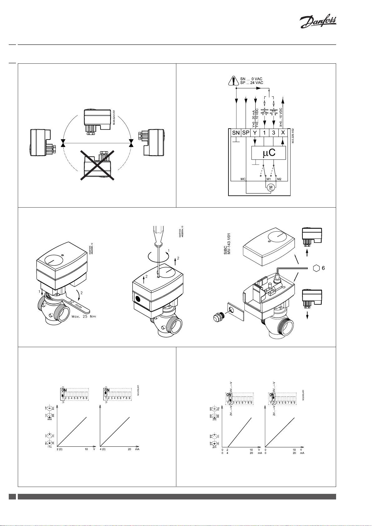
Mounting ➊
Fix the AME 13 SU on the valve ❷.
Wiring ❸
Do not touch anything on the PCB!
Switch o the power line before wiring
the actuator! Lethal voltage!
Wire the actuator according to the wiring
diagram.
Output signal
Output signal from the terminal X can be
used for indication of the current position.
Range depends on the DIP switch settings.
Supply voltage
Supply voltage (24 V~ -15 to +10%, 50 Hz)
must be connected to the terminals SN
and SP.
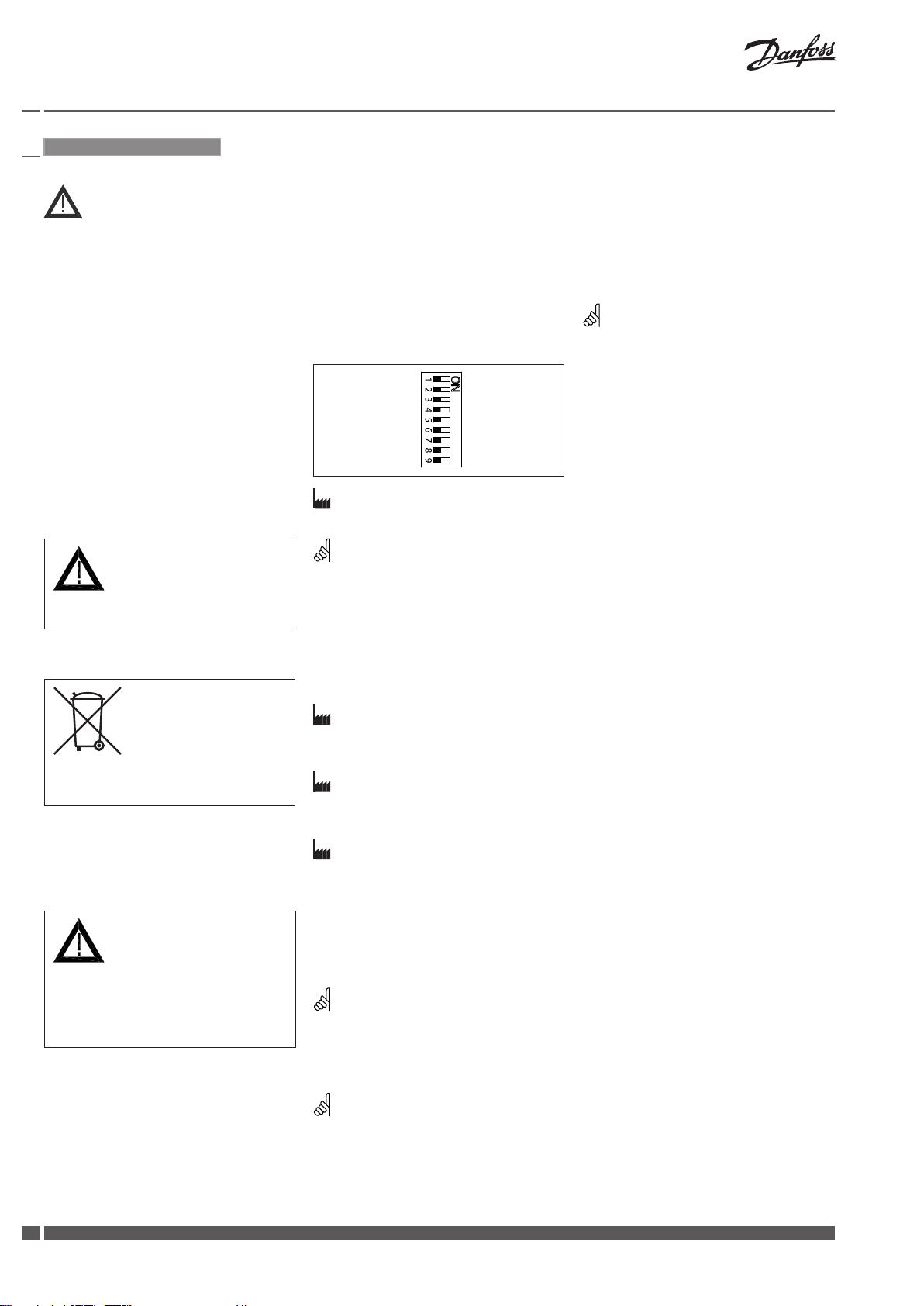
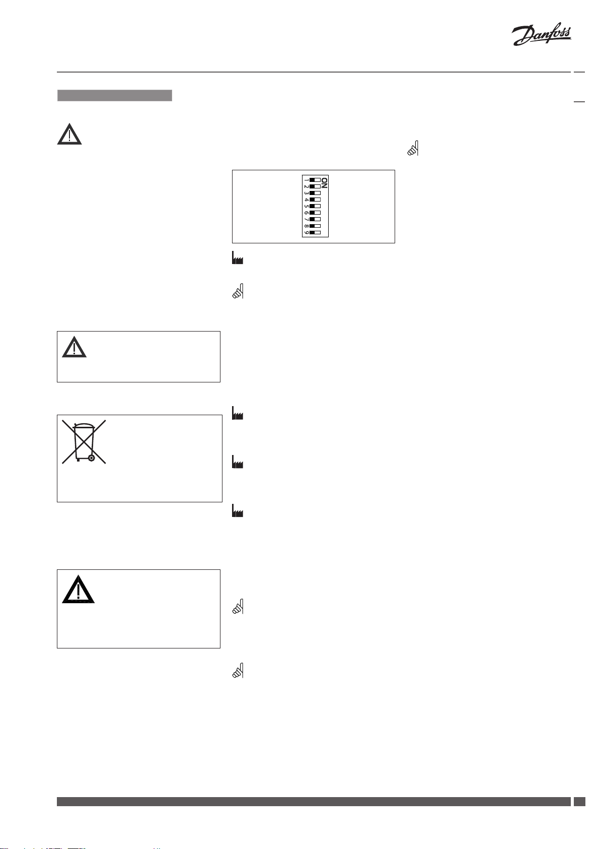
DIP switch settings
Factory settings:
ALL switches are on OFF position!
NOTE:
All combinations of DIP switches are
allowed. All functions that are selected are
added consecutively. There is only one logic
override of functionalities i.e. the switch No.6
Proportional /3 point, which sets actuator to
ignore control signal and works as a “simple”
3-point actuator.
SW1: U/I ❹
Factory setting is:
voltage control signal (0-10 V).
SW2: 2-10 V/0-10 V ❺
Factory setting is:
2-10 V.
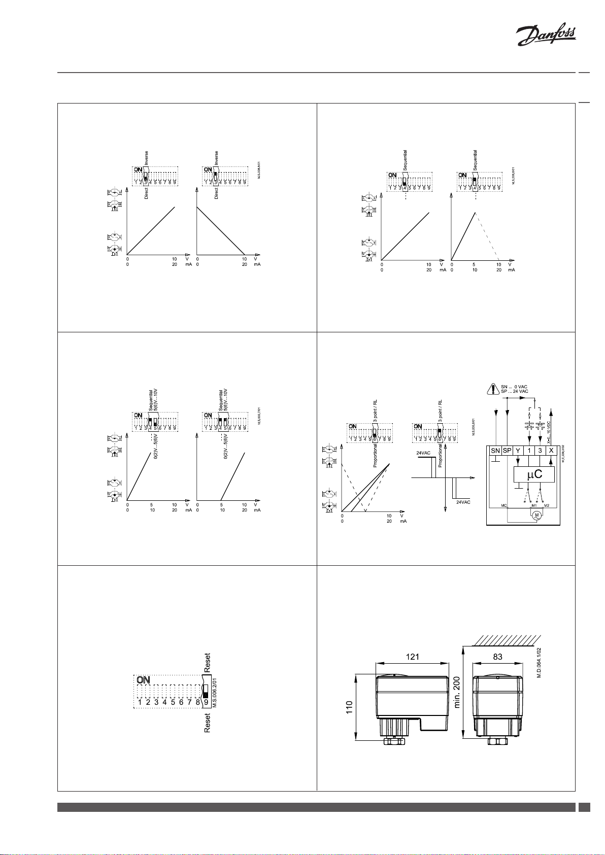
SW3: Direct/Inverse ❻
Factory setting is:
DIRECT
SW4: ---/Sequential ❼
Two actuators can be set to work parallel
with one control signal. If the SEQUENTIAL
is set than an actuator responds to split
control signal (see 0(2)-5(6) V/5(6)-10 V).
NOTE:
This combination works in combination with
switch No.5: 0(2)-5(6) V/5(6)-10 V.
U I
2 V_---V 0 V_- --V
Direct Inv erse
--- Se quential
0(2) V_5(6) V 5(6) V_10 V
Proport ional 3 point/ RL
Reset Res et
SW6: Proportional/3 point ❾
Actuator can operate as “simple” 3-point
actuator, if the 3-point function is selected.
Power supply should be connected on
SN and SP ports. On port 1 or 3 24 VAC
signal is connected for rising or lowering
of actuator. Return signal X indicates the
correct position.
NOTE:
if 3 point function is selected actuator does
not respond to any control signal on port Y.
It only rises and lowers spindle if power is
supplied on port 1 or 3.
SW7: Not in use
SW8: Not in use
SW9: Reset ❿
After the actuator has been connected
to power supply, the actuator will start
the self-adjustment procedure. The
indicator LED ashes until self adjustment
is nished. The duration depends on the
spindle travel and will normally last a few
minutes. The stroke length of the valve is
stored in the memory after self adjustment
has been completed. To restart self
adjustment, change the position of RESET
switch (switch No.9). If the supply voltage
is switched o or falls below 80 % in more
than 0.1 s, the current valve position will be
stored in the memory and all data remain
saved in the memory also after a power
supply cut-out.
Function test
The indicator light shows whether the
positioner is in operation or not. Moreover,
the indicator shows the control status and
faults.
Constant light
- normal operation
No light
- no operation or no power supply
Intermittent light (1 Hz)
- self adjusting-mode
Intermittent light (3 Hz):
- power supply too low
- insucient valve stroke (<20 s)
- end-position cannot be reached.
Control signal
Control signal from the controller must be
connected to terminals Y (input signal) and
SN (common) on the AME printed board.
4
DH-SMT/SI VI.AC.D3.8C Danfoss Heating
SW5: 0(2)-5(6) V/5(6)-10 V ❽
NOTE:
This function is available if switch No.4: ---/
Sequential is set.
Installation Guide AME 13 SU
DANSK
Sikkerhedsbestemmelser
For at undgå personskader og
erstatningsskader på produkter, er det
absolut nødvendig at gennemlæse
følgende instruktion.
Montering, opstart og vedligeholdelse må
kun foretages af kvaliceret og autoriseret
personale.
Forud for monterings- og
vedligeholdelsesarbejde på
regulatorenskal systemet være:
- trykløst
- nedkølet
- tømt
- rengjort
Leverandørens retningslinier skal følges.
Fjern ikke dækslet, før strømforsyningen
erhelt koblet fra.
Bortskaelsesinstruktion
Dette produkt skal, om muligt,
adskilles og sorteres i dets
forskellige materialegrupper,
før det genbruges eller
bortskaes.
Følg altid de lokale regulativer for
bortskaelse.
Montering ❶
Fastgør AME 13 SU på ventilen ❷.
Elektrisk tilslutning ❸
Forsyningsspænding
Forsyningsspændingen (24 V~ -15/+10%,
50 Hz) skal tilsluttes klemme SN og SP.
Indstilling af DIP kontakter
Fabriksindstilling:
Alle kontakter er I OFF position!
Bemærk:
Alle kombinationer af kontaktindstillinger
er tilladelige. Alle funktionsvalg er
tilføjet en efter en. Der er kun en logisk
overskridelse af funktionaliteten: Kontakt
Nr. 6 Proportional/3-punkt styring, som
sætter aktuatoren i stand til at ignorere
reguleringssignalet og arbejde som en
”simpel” 3- punkt motor
U/I ❹
Fabriksindstilling
Spændingssignal (0 - 10 V).
2 V-10/0V-10 V ❺
Fabriksindstilling:
2-10 V.
Direkte/Indirekte ❻
Fabriksindstilling:
DIREKTE
---/Sekvens ❼
To aktuatorer kan arbejde parallelt med et
reguleringssignal.
I SEKVENS indstilling reagerer aktuatoren
på delt styresignal (se 0(2)-5(6) V/5(6)-10 V).
U I
2 V_---V 0 V_- --V
Direkte I ndirekte
--- Sek vens
0(2) V_5(6) V 5(6) V_10 V
Proport ional 3-punk t/RL
Reset Res et
3 tilsluttes 24 VAC signal til åbne- lukke
funktion af aktuatoren. Udgangssignal X
indikerer korrekt position.
Bemærk:
Hvis 3-punkt funktionen er valgt, reagerer
aktuatoren ikke på signaler på klemme Y.
Motorspindelen bevæger sig kun opad eller
nedad ved signaler på klemme 1 eller 3.
Reset ❿
Efter tilslutning af forsyningsspænding,
vil aktuatoren starte en selvjusterings
procedure. LED indikatoren blinker indtil
selvjusteringen er færdig. Varigheden
afhænger af spindelvandringen og tager
normalt nogle få minutter. Ventilens
spindelvandring lagres i hukommelsen
efter selvjusteringen er færdig. For at
starte selvjustering, skiftes positionen
af RESET kontakten (kontakt Nr. 9). Hvis
forsyningsspændingen svigter eller
falder til under 80 % i mere end 0,1
sekund, vil den aktuelle ventilposition
lagres i hukommelsen og alle data bliver
bevaret i hukommelsen, også efter at
forsyningsspændingen afbrydes.
Funktions test
Lysdioden indikerer, om aktuatoren er
i drift, ligesom den viser driftsstatus og
eventuelle fejl.
• Konstant lys
- normal drift
• Intet lys
- ikke i drift, ingen strømforsyning
• Interval blink (1 Hz)
- selvjusteringsmodul
• Interval blink (3 Hz)
- strømforsyning for lav
- ventil slaglængde utilstrækkelig
- endestilling kan ikke nås
Rør ikke ved PCB!
Sluk for strømmen inden elektrisk
tilslutning af motoren! Kan være livsfarlig!
Tilslut motoren iht. ledningsdiagrammet.
Bemærk:
Denne kombination arbejder sammen med
kontakt Nr. 5: 0(2)-5(6) V/5(6)-10 V
0(2)-5(6) V/5(6)-10 V ❽
Styresignal
Styresignalet fra regulatoren skal tilsluttes
terminal Y (indgangssignal) og SN (fælles)
på AME´s klemrække.
Udgangssignal
Udgangssignal fra terminal X kan anvendes
til indikering af aktuel position.
Området afhænger af DIP kontakternes
indstilling.
Danfoss Heating VI.AC.D3.8C DH-SMT/SI
Bemærk:
Denne funktion er tilgængelig hvis kontakt
Nr. 4:---/Sekvens er indstillet.
Proportional/3-punkt ❾
Aktuatoren arbejder som en “simpel”
3-punkt aktuator, hvis 3-punkt funktionen
er valgt. Forsyningsspænding tilsluttes
klemmerne SN og SP. På klemmerne 1 og
55

Installation Guide AME 13 SU
LANGUAGEDEUTSCH
Sicherheitshinweise
Vor dem Einbau und der Inbetriebnahme
ist zur Vermeidung von Personenschäden
und Schäden an den Geräten die vorliegende Betriebsanleitung sorgfältig durc
Hzulesen und unbedingt zu beachten.
Einbau-, Inbetriebnahme- und
Wartungsarbeiten dürfen nur durch geschultes und autorisiertes Fachpersonal
durchgeführt werden.
Vor dem Einbau des Ventils und der
anschließenden Montage des Stellantriebs
und vor Wartungsarbeiten an der
Ventileinheit muss die Anlage:
- drucklos gemacht werden
- abkühlen
- entleert werden
- gereinigt werden.
Die Vorgaben des Anlagenherstellers oder
des Anlagenbetreibers sind zu beachten.
Entfernen Sie die Abdeckung nicht,
bevor die Stromversorgung komplett
ausgeschaltet ist.
Anweisung zur Entsorgung
Dieses Produkt sollte
ausgebaut und in dessen
Bestandteile zerlegt werden.
Sortieren Sie die einzelnen
Bestandteile entsprechend
der Entsorgungsgruppen zur
Wiederverwertung oder Entsorgung.
Beachten sie dabei immer die lokalen
Entsorgungsrichtlinien.
Montage ❶
AME 13 SU am Ventil ansetzen ❷.
Elektrischer Anschluß ❸
Bitte die Platine nicht direkt berühren!
Trennen Sie das Netzkabel vor der
Verdrahtung des Stellantriebs! Tödliche
Spannung!
Schließen Sie den Stellantrieb gemäß
demVerdrahtungsplan an.
Steuersignal
Das Steuersignal des Reglers ist an Klemme
Y (Eingangssignal) und Klemme SN
(Sammelklemme) an der AME-Printplatte
anzuschließen.
Ausgangssignal
Das Ausgangssignal von Klemme X kann
zur Anzeige der aktuellen Position benutzt
werden. Der Bereich hängt von der Brücke
ab.
Spannungsversorgung
Die Spannungsversorgung (24 V~ -15 bis
+10%, 50 Hz) ist an Klemme SN und SP
anzuschließen.
Einstellung der DIP Brücke
Werkseinstellung:
ALLE Schalter sind in der Position OFF!
BEMERKUNG:
alle Kombinationen von DIP Schalter
sind erlaubt. Gewählte Funktionen sind
hintereinandergelegt. Es gibt nur eine
logische Umsteuerung der Funktionen:
Brücke Nr.6 proportional/3-Punkt. Dadurch
wird der Antrieb so umgeschaltet, dass
das Signal ignoriert wird und arbeitet als
“üblicher” 3-Punkt Anrieb.
U/I ❹
Werkseinstellung:
Spannungsregelsignal (0 - 10V).
2 V-10/0 V-10 ❺
Werkseinstellung:
2-10 V .
Direct/Inverse ❻
Werkseinstellung:
DIRECT
---/Sequentiell ❼
Zwei Antriebe können parallel mit einem
Steuersignal arbeiten. Bei der Einstellung
SEQUENTIAL Antrieb reagiert auf geteilten
Steuersignal (sehe 0(2) V-5(6 V)/5(6) V-10V).
BEMERKUNG:
Diese Kombination funktioniert mit dem
Schalter No.5: 0(2) V-5(6 V)/5(6) V-10 V
U I
2 V_---V 0 V_- --V
Direct Inv erse
--- Se quentiell
0(2) V_5(6) V 5(6) V_10 V
Proport ionäl 3-Punk t/RL
Reset Res et
0(2) V-5(6) V/5(6) V-10 V ❽
BEMERKUNG:
diese Funktion ist wirksam, wenn der Schalter
No.4: ---/Sequentiell eingestellt ist.
Proportionäl/3-Punkt ❾
Bei der gewählten 3-Punkt Funktion kann
der Antrieb als “einfacher” 3-Punkt Antrieb
arbeiten. Die Spannungsversorgung ist an
Klemme SN und SP anzuschließen. Auf der
Klemme 1 oder 3 = 24 VAC Steuersignal
sorgt für stetigen oder absenken der
Antriebs. Das Ausgangssignal von Klemme
X kann zur Anzeige der aktuellen Position
benutzt werden.
BEMERKUNG:
wenn die 3-Punkt Funktion gewählt wird,
reagiert der Antrieb nicht auf irgendwelche
der Steuersignale Y Klemme. Der Antrieb
bewegt die Motorenspindel nach oben oder
nach unten bei dem Steuersignal auf Klemme
1 oder 3.
Reset ❿
Nach Einschalten der Stromversorgung
startet der Regelantrieb den
Selbstanpassungsvorgang. Die
Leuchtdiode blinkt, bis die Anpassung
abgeschlossen ist. Dies dauert
normalerweise einige Minuten,
abhängig von der Distanz der
Spindelbewegung. Die Hublänge des
Ventils wird nach abgeschlossener
Selbstanpassung im Speicher registriert.
Der Selbstanpassungsvorgang kann durch
Drücken der RESET-Taste wiederholt
werden (Schalter No. 9). Bei Ausfall der
Versorgungsspannung - oder beim
Absinken auf einen Wert kleiner 80
% - länger als 0,1 s, wird die aktuelle
Ventilposition im Speicher gespeichert.
Alle Daten sind also auch im Falle einer
Stromunterbrechung gesichert.
Funktionstest
Die Leuchtdiode zeigt den Motorbetrieb,
den Betriebszustand und eventuelle Fehler
an.
Dauerlicht
- normaler Betrieb
Kein Licht
- nicht in Betrieb oder keine
Stromversorgung
Blinklicht (1 Hz)
- Selbstanpassungsmodus
Blinklicht (3 Hz)
- Versorgungsspannung zu niedrig
- Ventilhublänge ungenügend (<20 s)
- Endposition nicht erreichbar.
6
DH-SMT/SI VI.AC.D3.8C Danfoss Heating

Installation Guide AME 13 SU
FRANCAIS
Sécurité
Pour éviter des dommages physiques et
matériels, il est absolument nécessaire
de lire attentivement et de respecter ces
instructions avant le montage et la mise
enservice.
Le travail d’assemblage, de démarrage
et de maintenance nécessaire doit être
eectué uniquement par un personnel
qualié, formé et autorisé.
Avant le travail d’assemblage et de
maintenance du contrôleur, le système
doit être:
- dépressurisé
- refroidi
- vidé
- nettoyé
Suivre les instructions du fabricant du
système ou de son service.
Ne pas retirer le capot avant d’avoir
totalement coupé l’alimentation.
Indications de mise au rebus
Ce produit peut être démonté
et tous ses composants
classés si possible en
diérentes catégories en
vuede leur recyclage ou
destruction
Dans tous les cas , suivre la législation
locale de mise au rebus.
Montage ❶
Fixer l’AME 13 SU sur la vanne ❷.
Branchement éléctrique ❸
Ne pas toucher la carte de circuit imprimé !
Couper l’alimentation avant de raccorder
l’actionneur ! Danger de mort !
Raccorder l’actionneur conformément au
schéma de branchement électrique.
Signal de commande
Le signal du régulateur doit être branché
sur la borne Y (signal d’entrée) et la borne
SN (commun) sur la carte imprimée de
l’AME.
Signal de sortie
Le signal de sortie de la borne X peut
servir pour indiquer la position actuelle. La
zone dépend des réglages du sélecteur de
fonction DIP.
Tension d’alimentation
La tension d’alimentation (24 V~-15/+10%,
50 Hz) doit être branchée aux bornes SN
et SP.
Réglages du sélecteur de fonction
DIP
Réglage d’usine:
TOUTES les commandes sont en position
ARRÊT!
REMARQUE:
Toutes les combinaisons des commandes DIP
sont possibles.
Toutes les fonctions sélectionnées sont
ajoutées l’une à l’autre. Il y a seulement un
pontage logique des fonctions: commande
6 Proportionnel/3 points qui fait le moteur
ignorer le signal de commande et fonctionne
comme un »simple« 3-points moteur.
U/I ❹
Réglage de l’usine:
le signal de commande de tension (0 - 10 V).
2 V-10/0 V-10 ❺
Réglage de l’usine:
2-10 V.
Direct/Inverse ❻
Réglage de l’usine:
DIRECT
---/Séquentiel ❼
Deux moteurs peuvent être réglés de telle
manière qu’ils fonctionnent parallèlement
avec un signal de commande. Si la fonction
SÉQUENTIEL est réglée, le moteur répond
au signal de commande »split«
(voir 0(2) V-5(6)/5(6) V-10 V).
REMARQUE:
Cette combinaison fonctionne en
combinaison avec la commande 5:
0(2) V-5(6 V)/5(6) V-10V.
U I
2 V_---V 0 V_- --V
Direct Inv erse
--- Sé quentiel
0(2) V_5(6) V 5(6) V_10 V
Proport ionnel 3 points /RL
Reset Res et
0(2) V-5(6) V/5(6) V-10 V ❽
REMARQUE:
Cette fonction est disponible, si la commande
4: ---/Séquentiel est réglée.
Proportionnel/3 points ❾
Le moteur peut fonctionner comme un
»simple« 3-points moteur, si la fonction
3-points est sélectionnée. Alimentation en
courant devrait être branchée aux bornes
SN et SP. 24VAC signal est branché aux
bornes 1 et 3 pour déplacer le moteur vers
le haut et vers le bas. Le signal X indique la
position correcte.
REMARQUE:
Si la fonction 3 points est sélectionnée,
le moteur ne répond à aucun signal de
commande sur la borne Y. Cette fonction
seulement déplace la broche vers le haut
et vers le bas, s’il y a de l’alimentation en
courant sur les bornes 1 et 3.
Exploitation ❿
Une fois alimenté, le moteur commence
un procédé d’auto-réglage. La diode
lumineuse clignote jusqu’à ce que
l’auto-réglage soit términé. Cela dure
normalement env. 2 minutes, suivant le
déplacement de la broche. La course de la
vanne est conservée en mémoire à la n de
l’auto-réglage. Le changement de position
de la commande R. À Z. (commande 9) fera
redémarrer l’auto-réglage. Si l’alimentation
est interrompue – ou chute à une valeur
inférieure à 80 % - pendant plus de 0,1
sec., la position actuelle de la vanne est
mémorisée. Toutes les données seront
donc mémorisées, même en cas de
coupure de courant.
Test de fonction
La diode lumineuse indique que le moteur
est en fonction. Elle indique aussi l’état de
marche et les erreurs éventuelles.
Lumière permanente
- marche normale
Pas de lumière
- fonction arrêtée, pas d’alimentation
Clignotements par intervalles (1 Hz)
- mode d’auto-réglage
Clignotement par intervalles (3 Hz)
- alimentation en courant trop faible
- course de vanne insusante (<20 s)
- la n de course ne peut pas être
atteinte.
Danfoss Heating VI.AC.D3.8C DH-SMT/SI
77

Installation Guide AME 13 SU
ESPAÑOL
Nota de seguridad
A n de evitar lesiones y daños a personas
y dispositivos, es absolutamente
imprescindible la lectura y puesta en
práctica de estas instrucciones antes de
llevar a cabo las operaciones de montaje
ypuesta en servicio.
Las operaciones necesarias de montaje,
puesta en marcha y mantenimiento
deberán ser realizadas únicamente
por personal debidamente cualicado,
formado y autorizado.
Antes de llevar a cabo cualquier operación
de montaje y mantenimiento del regulador,
el sistema debe ser:
- despresurizado
- refrigerado
- vaciado
- limpiado
Por favor, respete las instrucciones del
fabricante o el operador del sistema.
No retire la cubierta antes de haber
desconectado el suministro eléctrico
porcompleto.
Instucciones de eliminación
Este producto debe ser
desmontado y si es posible,
sus componentes deben ser
separados en varios grupos
antes de su reciclado o
destrucción.
Siga siempre la regulación local sobre
eliminación.
Montaje ❶
Montaje del AME 13 SU en la válvula ❷
Cableado ❸
¡No toque nada en la placa de circuito
impreso! ¡Tensión letal!
¡Desactive la línea de suministro eléctrico
antes de conectar el actuador!
Conecte el actuador de acuerdo con el
esquema de cableado.
Seńal de control
La seńal de control proveniente del
regulador deberá ser conectada al terminal
Y (seńal de entrada) y al terminal SN
(común) en el circuito impreso del AME.
Seńal de salida
La seńal de salida del terminal X puede
usarse para indicar la posición actual. El
rango dependerá de la conguración del
interruptor DIP.
Tensión de alimentación
La tensión de alimentación (24 V~15/+10%, 50 Hz) tiene que ser conectada a
los terminales SN y SP.
Las conguarciones del
interruptor DIP
Ajuste de fábrica:
Todos los interruptores tienen que estar en la
posición OFF!
IMPORTANTE:
Todas las combinaciones de los interruptores
están permitidas. Todas las funciones
seleccionadas serán añadidas una a la otra.
Solamente hay una sobreposición de las
funciones: el interruptor No.6 Proporcional/3
vías que hace que el actuador ignore la señal
y funcione como un “sencillo” actuador de
3 vías.
U/I ❹
Ajuste de fábrica:
señal de control de tensión (0 - 10 V).
2 V-10/0 V-10 ❺
Ajuste de fábrica:
2-10 V.
Directo/Inverso ❻
Ajuste de fábrica:
DIRECTO
---/Secuencial ❼
Se pueden ajustar dos acuadores
simultaneamenete que respondan a la
misma señal de control a la vez. Al elegir
SEQUENTIAL el actuador responderá a la
señal de control dividida
(vease 0 (2) V-5(6) V/5(6) V-10 V).
Nota:
Esta combinación funciona en combinación
con el interruptor No.5: 0(2)- 5(6) V/5(6)- 10V).
U I
2 V_---V 0 V_- --V
Directo I nverso
--- Se cuencial
0(2) V_5(6) V 5(6) V_10 V
Proporcio nal 3 vías/RL
Reset Res et
0(2)- 5(6) V/5(6)- 10V) ❽
Nota:
Esta función es posible al elegir el interruptor
No.4:---/Secuencial.
Proporcional /3 vías ❾
Al elegir la función de tres vías, el actuador
funcionará como un sencillo actuador
de tres vías. La corriente de alimentación
debe ser conectada a los puertos SN y SP.
En los puetros 1 y 3 la señal 24 VAC estará
conectada para que el actuador se mueva
hacia arriba o abajo. La señal X indica la
posicion correcta.
Importante:
Al elegir la función de 3 vías, el actuador
no responerá a ninguna de las señales de
control en el puerto Y. El vástago se moverá
hacia arriba o abajo si hay alimentación en
el puerto 1 ó 3.
Funcionamiento ❿
Después de suministrar corriente de
alimentación al actuador, éste inicia un
proceso de auto ajuste. El diodo LED
parpadea hasta que el proceso de auto
ajuste haya llegado a término. Este proceso
dura normalmente un par de minutos
dependiendo del recorrido del vástago.
El recorrido de la válvula es almaceneado
en la memoria después de terminado el
auto ajuste. Para empezar de nuevo el
auto ajuste pulsar el interruptor RESET
(interruptor No.9). Si se corta la tensión de
alimentación o en caso de que ésta caiga
por debajo de 80 % durante más de un
0,1 s, la posición actual de la válvula será
guardada en la memoria. De esta manera,
todos los datos quedarán guardados en
la memoria, incluso en caso de corte de
corriente.
Test de funcionamiento
El diodo luminoso indica si el motor está
funcionando. Además indica el estado de
funcionamiento y fallos eventuales.
Luce constantemente
- funcionamineto normal
No luce
- no está en marcha, no hay
alimentación
Luce intermitentemente a intervalos (1 Hz)
- estado de auto ajuste
Luce intermitentemente a intervalos (3 Hz)
- corriente de alimentación demasioado
baja
- recorrido de la válvula insucinete
(<20 s)
- el recorrido máximo no puede ser
alcanzado
8
DH-SMT/SI VI.AC.D3.8C Danfoss Heating

Installation Guide AME 13 SU
LANGUAGENEDERLANDS
Veiligheid
Om verwondingen aan personen en
schade aan de apparatuur te voorkomen
is het absoluut noodzakelijk om deze
instructies zorgvuldig te lezen en te
bestuderen.
Noodzakelijke (de)montage, inbedrijfstelling en onderhoud dient alleen door deskundig, getraind en bevoegd personeel
teworden uitgevoerd.
Voorafgaand aan montage-of
onderhoudswerkzaamheden moet
hetsysteem worden:
- afgesloten,
- afgekoeld,
- afgetapt en
- gereinigd.
Volg altijd de instructies van de
installatiebouwer-of beheerder op.
Verwijder de afdekkap niet voordat de
voedingsspanning volledig is uitgeschakeld
Afvalverwerking
Dit product of delen ervan
dienen te worden afgevoerd op
een milieuverantwoorde wijze.
Apparatuur die elektrische
onderdelen bevat, mag niet
samen met huishoudelijk
afval worden afgevoerd.
Deze apparatuur moet apart worden
ingezameld samen met ander elektrisch
en elektronisch afval conform de geldende
wetgeving.
Montage ❶
Plaats de AME 13 SU op de afsluiter ❷.
Elektrische aansluiting ❸
Gevaarlijke spanning, raak niets aan op
deprintplaat! Dodelijke spanning!
Schakel de stroom uit voordat de bedrading
van de servomotor wordt aangebracht!
Sluit de servomotor aan volgens het
aansluitschema.
Stuursignaal
Het stuursignaal van de regelaar wordt
aangesloten op klem Y (ingangssignaal) en
op klem SN (gemeenschappelijke nul) van
de AME printplaat.
Uitgangssignaal
Het uitgangssignaal van klem X (t.o.v. klem
SN) kan gebruikt worden als indicatie van
de klepstand. Het bereik hangt af van de
instelling van de DIP schakelaars.
Voedingsspanning
De voedingsspanning (24V~ -15 tot +10%,
50Hz) wordt aangesloten op de klemmen
SN (nul) en SP (24Vac).
DIP schakelaars
Fabrieksinstelling:
Alle schakelaars staan in de OFF (uit) positie!
OPMERKING:
Alle combinaties van DIP instellingen zijn
toegestaan. Alle gekozen funkties worden bij
elkaar opgeteld. Er is echter één uitzondering:
Schakelaar 6 Proportional/3 point, welke
de motor instelt als “simpele” 3-punts
servomotor.
Schakelaar 1: U/I ❹
Fabrieksinstelling:
0 - 10 V stuursignaal
Schakelaar 2: 2 V----/0 V---- ❺
Fabrieksinstelling:
2 V (4 mA)
Schakelaar 3: Direct/Inverse
(Direkt/Omgekeerd) ❻
Fabrieksinstelling:
Direct.
Schakelaar 4:
---/Sequential (volgorde) ❼
Twee motoren kunnen naar hetzelfde
signaal “luisteren”.
Als Sequential is ingesteld reageert de
motor op een gedeeld signaal.
Deze instelling werkt samen met
schakelaar 5.
U I
2 V_---V 0 V_- --V
Direct Inv erse
--- Se quential
0(2) V_5(6) V 5(6) V_10 V
Proport ional 3 point/ RL
Reset Res et
Schakelaar 5:
0(2)-5(6) V/5(6)-10 V ❽
Opm.:
Deze funktie is geldig als schakelaar 4 op
Sequential staat.
Schakelaar 6: Proportional/3 point
(Proportioneel/3punts) ❾
De servomotor werkt als een simpele
3-punts motor als de 3- punts funktie is
ingesteld.
Voedingsspanning wordt aangesloten op
de klemmen SN en SP. Op de klemmen
1 en 3 wordt 24Vac voor “omlaag” en
“omhoog” aangesloten. Uitgangs- signaal
X geeft de werkelijke stand aan.
Opmerking:
In de 3-punts funktie reageert de servomotor
niet op signalen via klem Y. De spindel
beweegt alleen bij spanning op klem 1 of
klem 3.
Schakelaar 9: Reset ❿
Nadat de servomotor is aangesloten op de
voedingsspanning begint de automatische
afstelprocedure. De indicatie LED knippert
tot de afstelling is beëindigd. De tijdsduur
is afhankelijk van de kleplift en bedraagt
gewoonlijk enkele minuten. De slag van de
klep wordt in het geheugen opgeslagen.
Om de afstelprocedure opnieuw te starten
dient de stand van RESET veranderd te
worden.
Wanneer de voedings-spanning wordt
uitgeschakeld of langer dan 0,1s onder 80
% daalt, wordt de momentele klepstand
in het geheugen opgeslagen en blijven
alle gegevens bewaard, ook na het
uitschakelen van de voeding.
Funktietest
De LED indicator toont het motorbedrijf,
bedrijfstoestand en eventuele fouten.
Continue aan
- normaal bedrijf
Continue uit
- geen bedrijf of geen
voedingsspanning
Knipperend (1 Hz)
- automatische afstelprocedure
Knipperend (3 Hz)
- voedingsspanning te laag
- onvoldoende klepslag (< 20 s)
- eindpositie onbereikbaar.
Danfoss Heating VI.AC.D3.8C DH-SMT/SI
99

Installation Guide AME 13 SU
SUOMI
Turvallisuushuomautus!
Nämä ohjeet on ehdottomasti luettava
jahuomioitava ennen kokoonpanoa ja
käyttöönottoa henkilö- ja
omaisuusvahinkojen välttämiseksi.
Ainoastaan ammattitaitoiset ja valtuutetut
henkilöt saavat tehdä kokoonpano-,
käynnistys- ja huoltotöitä.
Ennen säätimen kokoonpano- ja
huoltotöitä järjestelmälle on tehtävä
seuraavat toimenpiteet:
- Paineen poisto
- Jäähdytys
- Tyhjennys
- Puhdistus
Noudata järjestelmän valmistajan ohjeita.
Älä irrota kantta, ennen kuin virransyöttö
on täysin katkaistu.
Tuotteen hävittäminen jätteenä
Mikäli mahdollista tämä
tuote tulee purkaa ja lajitella
puretut osat ennen niiden
kierrättämistä tai
hävittämistä jätteenä.
Noudata aina paikallista lainsäädäntöä
ja jätehuoltomääräyksiä jätteiden
hävittämisestä.
Kiinnittäminen ❶
Kiinnitä AME 13 SU venttiiliin. ❷
Johdotus ❸
Älä koske mihinkään piirilevyllä!
Käännä virta pois päältä ennen
toimimoottorin kytkemistä!
Hengenvaarallinen jännite!
Kytke toimimoottori johdotuskaavion
mukaisesti.
Ohjaussignaali
Ohjaimen ohjaussignaali on liitettävä
painetun AME-piirin liitäntöihin Y
(sisäänmenosignaali) ja SN (tavallinen
signaali).
Lähtösignaali
X-liitännän lähtösignaalia voidaan käyttää
nykyisen sijainnin ilmaisemiseen. Alue
määräytyy DIP-kytkinasetusten mukaan.
Käyttöjännite
Käyttöjännite (24 V~ –15– +10 %, 50 Hz) on
yhdistettävä SN- ja SP-liitäntöihin.
DIP-kytkinasetukset
Tehdasasetukset:
Kaikki kytkimet ovat OFF-asennossa!
HUOMAUTUS:
Kaikki DIP-kytkinasetusten yhdistelmät
ovat sallittuja. Kaikki valitut toiminnot
yhdistetään keskenään. Vain yksi logiikka
ohittaa toiminnot: kytkimen nro 5
Suhteellinen /kolmipiste -asetus, joka
määrittää käyttölaitteen jättämään
signaalin huomiotta, jolloin se toimii
yksinkertaisena kolmipistekäyttölaitteena.
U/I ❹
Tehdasasetus:
Jänniteohjaussignaali (0–10 V).
2–10 tai 0–10 V ❺
Tehdasasetus:
2–10 V
Suora tai käänteinen ❻
Tehdasasetus:
SUORA
---/vaiheittainen ❼
Kaksi käyttölaitetta voidaan määrittää
toimimaan rinnakkain samasta
ohjaussignaalista. Jos vaiheittaisuus
otetaan käyttöön, käyttölaite reagoi
jaettuun ohjaussignaaliin. Lisätietoja on
kohdassa 0(2)–5(6) V/5(6)–10V.
HUOMAUTUS:
Tämä yhdistelmä toimii yhdessä kytkimen 5
kanssa: 0(2)–5(6) V/5(6)–10V
0(2)–5(6) V/5(6)–10V ❽
HUOMAUTUS:
Tämä toiminto on käytettävissä, jos kytkin 4
---/vaiheittainen on määritetty.
U I
2 V_---V 0 V_- --V
Suora Kään teinen
--- vai heittainen
0(2) V_5(6) V 5(6) V_10 V
Proport ional 3 pisteine n/RL
Reset Res et
Suhteellinen/3-pisteinen ❾
Käyttölaite toimii yksinkertaisena
kolmipisteisenä käyttölaitteena, jos
valitaan kolmipisteinen toiminta.
Virransyöttö on yhdistettävä SN- ja
SP-portteihin. 24 voltin AC-signaali
yhdistetään porteissa 1 ja 3 käyttölaitteen
avautumis- ja sulkeutumistoimintoihin.
Paluusignaali X ilmaisee oikean sijainnin.
HUOMAUTUS:
Jos 3-pisteinen toiminta valitaan, käyttölaite
ei reagoi portin Y signaaliin. Se nostaa ja
laskee karaa vain, jos portteihin 1 tai 3
syötetään virtaa.
Nollaaminen ❿
Kun käyttölaite on yhdistetty
virtalähteeseen, se aloittaa
itsesäätötoimet. LED-merkkivalo vilkkuu,
kunnes itsesäätötoimet on tehty. Kestoaika
määräytyy karan liikkeen mukaan, ja on
tavallisesti muutama minuutti. Venttiilin
karan liikkeen pituus tallennetaan muistiin,
kun itsesäätötoimet on tehty.
Voit aloittaa itsesäädön uudelleen
muuttamalla RESET-kytkimen asentoa
(kytkin 9). Jos virransyöttö katkeaa tai
putoaa alle 80 prosenttiin yli 0,1 sekunnin
ajaksi, nykyinen venttiilin sijainti ja kaikki
tiedot tallennetaan muistiin. Ne säilyvät
siellä sähkökatkon ajan.
Toimintojen testaaminen
Merkkivalo ilmaisee, onko käyttölaite
käytössä vai ei. Lisäksi merkkivalo ilmaisee
ohjaustilan ja viat.
Palaa jatkuvasti
- normaali toiminta
Ei valoa
- ei toiminnassa tai ei virransyöttöä.
1 Hz:n taajuudella vilkkuva valo
- itsesäätötila
3 Hz:n taajuudella vilkkuva valo
- virransyöttö ei riitä
- venttiilin iskunpituus ei riitä (alle 20 s)
- loppusijaintia ei voi
saavuttaa.
10
DH-SMT/SI VI.AC.D3.8C Danfoss Heating

Installation Guide AME 13 SU
POLSKI
Warunki bezpieczeństwa
W celu uniknięcia zranienia osób
uszkodzenia urządzeń należy bezwzględnie
przed montażem i uruchomieniem siłownika
zapoznać się dokładnie z niniejszą instrukcją.
Czynności związane z montażem,
uruchomieniem i obsługą mogą być
dokonywane wyłącznie przez osoby
uprawnione i odpowiednio
wykwalikowane.
Przed montażem i obsługą konserwacyjną
należy:
- zrzucić ciśnienie,
- ostudzić urządzenie
- opróżnić układ,
- oczyścić układ
Należy postępować zgodnie z instrukcjami
producenta lub operatora systemu.
Nie zdejmować pokrywy przed całkowitym
odłączeniem zasilania.
i
Instrukcja usuwania odpadów
Ten produkt powinien być
rozebrany a jego komponenty
posegregowane, jeśli to
możliwe, na różne grupy
przed poddaniem
recyklingowi lub utylizacji.
Zawsze stosuj się do miejscowych
przepisów w zakresie usuwania odpadów.
Montaż ❶
Zamontować siłownik AME 13 SU
na zaworze. ❷
Okablowanie ❸
Nie wolno niczego dotykać na pł ytce
drukowanej!
Przed przystąpieniem do podłączania
do siłownika przewodów elektrycznych
należy odłączyć zasilanie sieciowe!
Zagrożenie życia!
Podłączyć siłownik zgodnie z podanym
schematem.
Sygnał sterujący
Sygnał sterujący ze sterownika musi być
podłączony do wyprowadzeń Y (sygnał
wejściowy) oraz SN (masa) na płytce
drukowanej siłownika AME.
Sygnał wyjściowy
Sygnał wyjściowy z wyprowadzenia X
może być użyty do wskazania bieżącej
pozycji. Zakres zależy od ustawień
przełącznika DIP.
Napięcie zasilania
Napięcie zasilania
(24 V~ -15 do +10%, 50 Hz) musi być
podłączone do wyprowadzeń SN i SP.
Ustawienia przełącznika DIP
Proporcjona lny
Ustawienia fabryczne:
wszystkie przełączniki są w położeniu OFF!
UWAGA:
Dozwolone są wszystkie kombinacje
przełączników DIP.
Wszystkie wybierane funkcje są sumowane.
Istnieje tylko jedno logiczne ominięcie
funkcjonalności: przełącznik nr 6
Proportional /3 point (Proporcjonalny/3punktowy), który powoduje, że siłownik
ignoruje sygnał sterujący i działa jako prosty
3-punktowy siłownik.
U/I ❹
Ustawienie fabryczne:
sterowanie sygnałem napięciowym
(0 - 10 V).
2-10 V/0-10 V ❺
Ustawienie fabryczne:
2 V-10 V.
Direct/Inverse ❻
Ustawienie fabryczne:
DIRECT
---/Sequential ❼
Dwa siłowniki mogą być sterowane
równolegle jednym sygnałem sterującym.
Jeśli wybrana jest opcja SEQUENTIAL,
siłownik reaguje na dzielony sygnał
sterujący (patrz 0(2) V-5(6 V)/
5(6) V-10 V).
U I
2 V_---V 0 V_- --V
Zgodnie Od wrotnie
--- Sek wencyjnym
0(2) V_5(6) V 5(6) V_10 V
Reset Res et
3-punk towy/RL
UWAGA :
To ustawienie działa w połączeniu z
przełącznikiem nr 5: 0(2) V-5(6 V)/
5(6) V-10 V
0(2) V-5(6 V)/5(6) V-10 V ❽
UWAGA :
Ta funkcja jest dostępna, gdy ustawiony jest
przełącznik nr 4: ---/Sequential.
Proportional/3 point ❾
Siłownik może funkcjonować jako prosty
siłownik 3- punktowy po wybraniu
opcji 3-point. Napięcie zasilania należy
podłączyć do wyprowadzeń SN i SP. Do
wyprowadzenia 1 i 3 podłączone jest
sygnał 24 VAC, służący do podnoszenia i
opuszczania siłownika. Zwrotny sygnał X
wskazuje pozycję siłownika.
UWAGA :
Jeśli wybrano opcję 3-point, siłownik nie
reaguje na jakikolwiek sygnał sterujący
na wyprowadzeniu Y. Siłownik będzie
podnosił i opuszczał wrzeciono, jeśli na
wyprowadzenia 1 i 3 zostanie podane
napięcie.
Reset ❿
Po podłączeniu siłownika do zasilania
rozpoczyna się procedura samoregulacji.
Dioda LED błyska do momentu
zakończenia tego procedury. Trwa to
zazwyczaj parę minut w zależności
od skoku wrzeciona. Po zakończonym
procesie samoregulacji wartość skoku
zaworu jest zachowana w pamięci. Zmiana
pozycji przełącznika RESET (przełącznik
nr 6) ponownie wyzwala proces
samoregulacji. Jeżeli napięcie zasilające
zostanie odcięte lub przez okres ponad 0,1
sekundy spadnie poniżej 80 %, to aktualna
pozycja zaworu jest chowana w pamięci;
zapewnia to, zachowana zachowanie
wszystkich danych - również w przypadku
przerw w zasilaniu.
Test działania
Dioda świetlna wskazuje, czy silnik jest
aktywny czy też nie. Co więcej, dioda LED
wskazuje też status sterowania i błędy.
Stałe świecenie
- normalna pracaBrak świecenia
- brak działania lub zasilania
Miganie z częstotliwością 1 Hz
- tryb samoregulacji
Miganie z częstotliwością 3 Hz
- zbyt niskie napięcie zasilania
- niedostateczny skok zaworu (<20 s)
- nie można osiągnąć położenia
krańcowego.
Danfoss Heating VI.AC.D3.8C DH-SMT/SI
1111

Installation Guide AME 13 SU
LANGUAGEРУССКИЙ
Техника безопасности
Во избежание несчастных случаев ивыхода устройства из строя необходимо изучить и соблюдать настоящее руководство.
Монтаж, наладка и сервисное
обслуживание устройства должны
осуществляться квалифицированным
персоналом, допущенным к данным
видам деятельности.
Работы, непосредственно связанные
стехнологической системой,
следует выполнять в соответствии
синструкциями по ее эксплуатации.
Перед началом работ по монтажу
иобслуживанию регулятора необходимо
произвести следующие действия
струбопроводной системой:
- сбросить давление
- охладить систему
- слить воду
- очистить систему
Не снимайте крышку до того, как
питание будет полностью отключено.
Не снимайте крышку до того, как
питание будет полностью отключено.
Инструкция по утилизации
Данная продукция
подлежит демонтажу
начасти, для раздельной
утилизации составных
компонентов.
Всегда соблюдайте местные правила
утилизации.
Установка ❶
Закрепить электропривод AME 13 SU на
клапане. ❷
Схема электрических
соединений ❸
Не прикасайтесь к открытым
контактам!
Отключать линию питания перед
монтажом проводки электропривода!
Возможен летальный исход!
Смонтируйте проводку привода
согласно электрической схеме.
Управляющий сигнал
Управляющий сигнал с регулятора
подается на клеммы Y (входной сигнал) и
SN (ноль) платы AME.
Выходной сигнал
Выходной сигнал с клеммы Х может быть
использован для индикации текущего
положения. Диапазон зависит от
настроек переключателя DIP.
Напряжение питания
Напряжение питания (24 В переменного
тока от –15 до +10%, 50 Гц) подается на
клеммы SN и SP.
Настройки переключателя DIP
Заводские установки:
ВСЕ переключатели находятся в
положении OFF (выключено).
ПРИМЕЧАНИЕ:
Приемлемы все комбинации
переключателей DIP. Все выбранные
функции добавляются друг к другу.
Существует только одно логическое
перерегулирование функций:
переключатель № 6 – (аналоговый/
импульсный) настраивать исполнительный механизм таким образом
аналоговый, что он игнорирует
управляющий сигнал и работает как
импульсный исполнительный механизм.
U/I (напряжение/ток) ❹
Заводская установка:
управляющий сигнал напряжения 0 - 10 B.
2-10 B/0 - 10 B ❺
Заводская установка:
2-10 B.
Прямо/обратно ❻
Заводская установка:
ПРЯМО.
---/последовательно ❼
Существует возможность установить
два исполнительных механизма так, что
они работают параллельно, с одним
управляющим сигналом. Если настроена
функция ПОСЛЕДОВАТЕЛЬНО, то
исполнительный механизм реагирует на
управляющий сигнал «сплит»
U I
2 V_---V 0 V_- --V
Direct Inv erse
--- Se quential
0(2) V_5(6) V 5(6) V_10 V
Proport ional 3 point/ RL
Reset Res et
(см. 0(2) - 5(6) В/5(6) - 10 В).
ПРИМЕЧАНИЕ:
Данная схема работает в комбинации с
переключателем № 5:
0(2) - 5(6) В/5(6) - 10 В.
0(2) - 5(6) В/5(6) - 10 В ❽
ПРИМЕЧАНИЕ:
Данная функция имеет место лишь в
случае, если настроен переключатель
№ 4: ---/последовательно.
Аналоговый/импульсный ❾
Исполнительный механизм
может работать как импульсный
исполнительный механизм при условии,
что выбрана импульсная функция.
Электропитание подается на входы SN
и SP. На входы 1 и 3 подается сигнал
24 В переменного тока для подъема
и опускания штока исполнительного
механизма. Выходной сигнал Х
показывает текущее положение.
ПРИМЕЧАНИЕ:
В случае, если выбрана импульсная
функция, исполнительный механизм
не реагирует ни на какой аналоговый
управляющий сигнал на входе Y.
Исполнительный механизм поднимает
и опускает шток только в случае, если
электропитание подается на вход 1
или 3.
Reset (Сброс) ❿
После подачи тока на исполнительный
механизм последний начинает
процесс автоподстройки. Об
этом свидетельствует мигание
светодиода, которое продолжается до
окончания процесса автоподстройки.
Продолжительность процесса
обычно составляет несколько минут,
в зависимости от перемещения
штока. Величина хода клапана
после окончания автоподстройки
регистрируется в запоминающем
устройстве. Процесс автоподстройки
возобновляется нажатием на кнопку
сброса «RESET» (переключатель № 9).
При сбросе напряжения питания
или при его падении более чем на
80 % в течение более 0,1 с, текущее
положение клапана регистрируется
в запоминающем устройстве. Таким
образом, вся информация сохраняется в
запоминающем устройстве, в том числе
в случаях сбоя напряжения питания.
12
DH-SMT/SI VI.AC.D3.8C Danfoss Heating

Installation Guide AME 13 SU
Функциональный тест
Световой диод наряду с индикацией
задействования привода производит
также индикацию рабочего состояния и
возможных ошибок.
Постоянное свечение
- обычное рабочее состояние
эксплуатации
Отсутствие свечения
- выключение, напряжение
отключено.
Прерывистое свечение (1 Гц):
- режим автоподстройки
Прерывистое свечение (3 Гц):
- электропитание слишком мало
- недостаточная величина времени
хода клапана (<20 с)
- невозможность входа в исходное
положение.
Danfoss Heating VI.AC.D3.8C DH-SMT/SI
1313

Installation Guide AME 13 SU
中文
安全注意事项
为避免发生人身和设备事故,请仔细阅读
本手册。
安装、调试、维修必须由专业人员进行。
在对控制器进行安装和维护之前,必须将
系统:
- 减压
- 冷却
- 清空
- 清洁
请遵循系统制造商或系统操作人员的说明。
电源未完全关闭前,请勿取下顶盖
弃置说明
在回收或丢弃前,应当将本
产品拆卸并对元件进行归
类
请遵循当地的废弃法规。
DIP 拨动开关的设定
出厂设定_
所有位都在 OFF 位置。
注意:
允许对 DIP 拨动开关进行任意组合。 所有
选定的功能将依次添加。 只有一种功能逻
辑操控,即拨动开关第 6 位比例控制/三点
控制,它将把驱动器设为不理会控制信号,
而是作为“简单的”三点驱动器使用。.
U/I ❹
出厂设定:
电压控制信号
2-10 V/0-10 V ❺
出厂设定:
2--10 V.
U I
2 V_---V 0 V_- --V
正向 反向动作
---
0(2) V_5(6) V 5(6) V_10 V
比例控制
Reset Res et
顺序动作
三点控制/RL
复位 ❿
驱动器第一次通电后将自动进行行程自检,
自检时 LED 指示灯闪烁直到自检结束。
自检的时间根据行程大小和速度快慢各不
相同,大致需几分钟时间。自检结束后行
程信息被记录到存储器中。将拨动开关的
第 9位拨到复位位置也可启动自检进程。电
源断电或电压降低于 80 % 的时间超过 0.1
秒,所有的当前数据被保存到存储器中。
功能测试功能测试
LED 指示灯可提供当前状态和故障指示:
持续亮
- 正常工作
不亮
- 没有任何操作或无电源电压
闪烁(1 Hz)
- 自检中
闪烁(3 Hz)
- 电源电压过低
- 行程不对(<20 s)
- 不能到达末端位置
安装 ❶
将 AME 13 SU 驱动器安装到阀体上。❷
接线 ❸
不要碰触电路板上的任何元件!
接线前请先断开电源!致命的电压!
请按接线图接线
控制信号
从控制器来的控制信号接到 AME 的 Y 端
(输入信号)和 SN 端(公共端)。
阀位反馈
阀位反馈信号从 X 端输出,SN 为公共端。
电源电压
电源电压(24V -15 % 到+10 % ,50 Hz)连
接到端子 SN 和 SP。
正向/反向动作 ❻
出厂设定:
正向
---/顺序动作 ❼
两个驱动器可共用一个控制
信号并联工作。选择顺序动
作功能后控制信号将被分割
(0(2)-5(6)V/5(6)-10 V)。
注意:
此项功能与拨动开关第 5 位配合使用。
0(2)V-5(6V)/5(6)V-10 V。
0(2) V-5(6) V/5(6)-10 V ❽
注意:
此项功能当拨动开关第 4 位设为顺序动作
时有效。
比例控制/三点控制 ❾
驱动器可设定为比例控制或三点控制。三点
控制时,电源连接到 SP 和 SN 端子,24VAC
控制信号分别接到端子 1 用 来打开或关闭
阀门。X 端子为阀位反馈。
注意:
选择三点控制以后驱动器不对 Y 端子的控
制信号作出反应。
14
DH-SMT/SI VI.AC.D3.8C Danfoss Heating

Installation Guide AME 13 SU
Danfoss Heating VI.AC.D3.8C DH-SMT/SI
1515

Installation Guide AME 13 SU
73690620/VI.AC.D3.8C
Produced by Danfoss A/S © 09/2010
 Loading...