

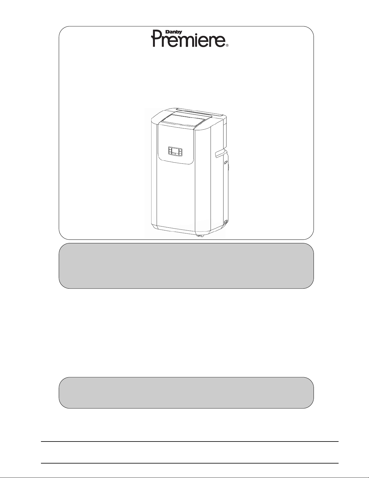
Owner’s Use and Care Guide
Guide de soin d’utiliser-et
Guía a utilizar y a cuidar
Model • Modèle
DPAC 9009
CAUTION: Read and follow all safety rules and operating instructions before first use
of this product.
MISE EN GARDE : Veuillez lire attentivement les consignes de sécurité et les directives
d'utilisation avant l'utilisation initiale de ce produit.
PORTABLE AIR CONDITIONER
Table of contents . . . . . . . . . . . . . . . . . . . . . . 1
CLIMATISEUR PORTATIF
Table des matières . . . . . . . . . . . . . . . . . . . . 13
Danby Products Ltd, PO Box 1778, Guelph, Ontario Canada N1H 6Z9
Danby Products Inc, PO Box 669, Findlay, Ohio USA 45839-0669
Version 1.10.08 JF
KEEP THESE INSTRUCTIONS FOR FUTURE REFERENCE: If the Dehumidifier changes
ownership, be sure this manual accompanies the unit.
CONSERVER CES INSTRUCTIONS POUR CONSULTATION ULTÉRIEURE: En cas de revente
du déshumidificateur, ce manuel doit être inclus avec l’appareil.

TABLE OF CONTENTS
UNIT SPECIFICATIONS . . . . . . . . . . . . . . . . . . . . . . . . . . . . 2
PART IDENTIFICATION . . . . . . . . . . . . . . . . . . . . . . . . . . . . 3
IMPORTANT SAFETY INFORMATION
Electrical Specifications . . . . . . . . . . . . . . . . . . . . . . . . . . . . . . . . . 3
Energy Saving Tips . . . . . . . . . . . . . . . . . . . . . . . . . . . . . . . . . 4
INSTALLATION . . . . . . . . . . . . . . . . . . . . . . . . . . . . . . . . . 5
Window Kit Installation . . . . . . . . . . . . . . . . . . . . . . . . . . . . . . . . . 5
OPERATION
Features of the Control Panel . . . . . . . . . . . . . . . . . . . . . . . . . . . . 6
Air Conditioning . . . . . . . . . . . . . . . . . . . . . . . . . . . . . . . . . . . . . . 7
Dehumidifier . . . . . . . . . . . . . . . . . . . . . . . . . . . . . . . . . . . . . . 8
Fan . . . . . . . . . . . . . . . . . . . . . . . . . . . . . . . . . . . . . . . . . . . . . . . . . 8
Auto Timer . . . . . . . . . . . . . . . . . . . . . . . . . . . . . . . . . . . . . . . . . . . . 9
Remote Control Features . . . . . . . . . . . . . . . . . . . . . . . . . . . . 9
CARE AND MAINTENANCE . . . . . . . . . . . . . . . . . . . . . . 10
TROUBLESHOOTING . . . . . . . . . . . . . . . . . . . . . . . . . . . 11
Warranty . . . . . . . . . . . . . . . . . . . . . . . . . . . . . . . . . . . . . . . . . . . 12
1
WELCOME
Thank you for choosing a Danby appliance to provide you and your family with
all of the “Home Comfort” requirements of your home, cottage, or office. This
Owner’s Use and Care Guide will provide you with valuable information
necessary for the proper care and maintenance of your new appliance. If
properly maintained, your Danby appliance will give you many years of trouble
free operation. Please take a few moments to read the instructions thoroughly
and familiarize yourself with all of the operational aspects of this appliance.
Your Danby Portable Air-Conditioner is a multi-functional room air-exchanging,
air-processing appliance, designed to offer you the functions of; Air
Conditioning, Dehumidifying, and Independent Fan. Each individual mode is
featured with “oscillating” air swing capabilities. This unit can be conveniently
moved from room to room within your home and set up in just minutes. Imagine
the convenience of 4 Season Home Comfort at your fingertips, anywhere,
anytime.
For easy reference, may we suggest you attach a copy of your sales slip/receipt
to this page, along with the following information, located on the manufacturers
nameplate on the rear panel of the unit.
Model Number:
Serial Number:
Date of Purchase:
This information will be necessary if your unit requires servicing and/or for
general inquiries. To contact a Customer Service Representative, call Danby
TOLL FREE: 1-800-26-
(1-800-263-2629)
2
Model Number DPAC9009
Voltage/Frequency 115V-60Hz
Noise Level 48.5 dB
Fan Speeds 3
Cooling Capacity 9000BTU
Refrigerant R410A
Unit Weight 27.2 kg (60lbs)
Airflow CFM High/Med./Low 342 / 318 / 288
Dimensions (W) x (D) x (H)(inches) 17.2”x 15.3”x 30.5”
Dimensions (W) x (D) x (H) (mm) 475 / 460 / 870
Remote Control Yes
Time of Day Clock No
Auto-Timer Yes
UNIT SPECIFICATIONS
NOTE: Continuing research results in steady improvement. Therefore, this information
and these specifications are subject to change without notice.
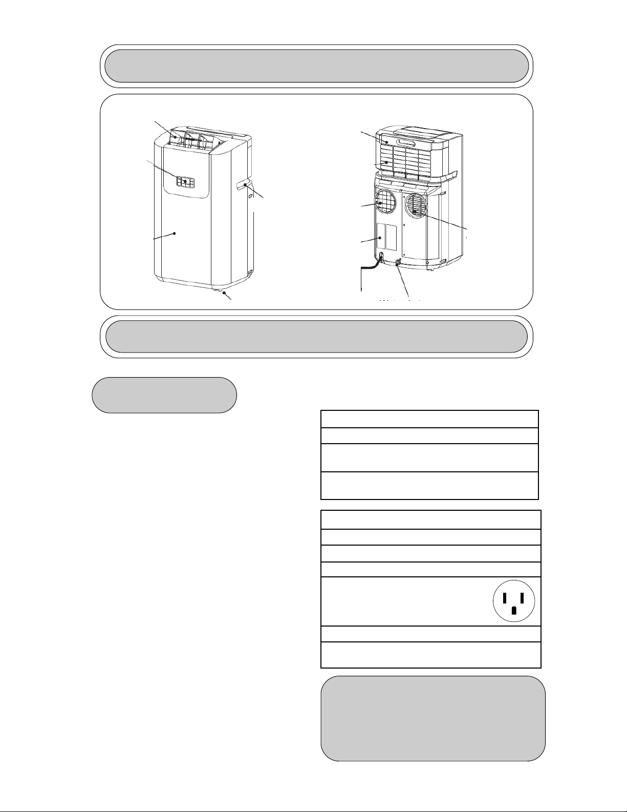
PART IDENTIFICATION
IMPORTANT SAFETY INFORMATION
READ ALL SAFETY INFORMATION BEFORE USING
1) Check available power supply and
resolve any wiring problems BEFORE
installation and operation of this unit. All
wiring must comply with local and national
electrical codes and be installed by a
qualified electrician. If you have any
questions regarding the following
instructions, contact a qualified electrician.
2) This appliance draws 10 nameplate amps
under Cooling Mode and may be used in
any properly wired, general purpose 13 amp
household grounded receptacle.
3) For your safety and protection, this unit is
grounded through the power cord plug when
plugged into a matching wall outlet. If you
are not sure whether the wall outlets in your
home are properly grounded, please consult
a qualified electrician.
WARNING: Improper connection of the
grounding plug can result in risk of Fire,
Electric Shock, and/or injury to Persons
associated with the appliance. Check with a
qualified service representative if in doubt
that the appliance is proplery grounded.
4) DO NOT USE PLUG ADAPTERS OR
EXTENSION CORDS WITH THIS UNIT. If it
is necessary to use an extension cord with
this unit, use an approved “air conditioner”
extension cord only (available at most local
hardware stores).
5) To avoid the possibility of personal injury,
always disconnect the power supply to the
unit before installing and/or servicing.
ELECTRICAL
SPECIFICATIONS
TABLE 1
Suggested Individual Branch Circuit
Nameplate Amps *AWG Wire Size
10 16
AWG- American Wire Gauge
*Based on copper wire at 105°C temperature rating.
TABLE 2
Receptacle and Fuse Types
Rated Volts 125
Amps 13
Wall Outlet
Fuse Size 15
Time Delay Fuse Plug Type
(or Circuit Breaker)
CAUTION: Do not leave this unit
unattended in a space where people or
animals cannot react to a failed unit are
located. A failed unit can cause extreme
overheating or death in such an
enclosed, unattended space.
3
Air Exhaust
LCD
Display
Front
Panel
Handles
Wheels
Air Filter
Air inlet
Air outlet
Cover
Electricity
cable
Water drain
Air inlet

POWER SUPPLY
CORD
The power cord supplied with this air conditioner contains a
device that senses damage to the power cord. To test if your
power cord is working properly, you must do the following:
IMPORTANT SAFETY INFORMATION
ENERGY-
SAVING TIPS
Your Danby appliance is designed to be highly efficient in energy
savings. Follow these recommendations for greater efficiency.
1) Select a thermostat setting that suits your
comfort needs and leave at that chosen
setting.
2) The air filter is very efficient in removing
airborne particles. Keep the air filter clean
at all times.
3) Use drapes, curtains or shades to keep
direct sunlight from penetrating and heating
room, but do not allow drapes or curtains to
obstruct the air flow around the unit.
4) Start your air conditioner before the
outdoor air becomes hot and
uncomfortable, to avoid an initial period of
discomfort while the unit is cooling off the
room. Use of the automatic start/stop
programmable TIMER feature can be a
major asset in this regard if utilized to the
fullest extent.
5) When outdoor temperatures are cool
enough, turn the air conditioner off and use
the FAN MODE. This circulates indoor air,
providing some cooling comfort while
utilizing less electricity.
NOTE: The power cord supplied with this
air conditioner contains a current leakage
detection device designed to reduce the
risk of fire. In the event the power supply
cord is damaged, it cannot be repaired
and must be replaced with a new cord
from the product manufacturer.
• Under no circumstances should this
device be used to turn the unit on or off.
• The “RESET” button must always be
pushed in (engaged) for correct operation.
• The power supply cord must be replaced
if it fails to reset when the “TEST” button
is pushed in.
1) Connect the power supply cord to an
electrical outlet.
2) The power supply cord has two buttons
located on the head of the plug. One
button is marked “TEST”, and the other is
marked “RESET”. Press the “TEST”
button; you will hear a click as the
“RESET” button pops out.
3) Press the “RESET” button; you will
hear a click as the button engages.
4) The power supply cord is now
energized and supplying electricity to the
air conditioner (on some products this is
also indicated by a light on the plug
head).
4

INSTALLATION
WINDOW KIT
Air Conditioning Mode ONLY
Your window kit has been designed to fit most standard “vertical”/”horizontal” windows up to
a maximum height of 80” (203cm). For vertical window applications, multi lock positions are
provided on the edge of each slider section to secure each sliding section together.
1) Select a suitable location, making sure you have access to an electrical outlet.
2) Install the flexible hose to the rear side of the unit. Insert the hose collar on top of the
exhaust opening and twist to lock into position.
3) Install the adjustable Window Slider Kit as required (see Fig. 3a & 3b).
4) Install the opposite end of the flexible exhaust hose into the window exhaust adapter.
5) Install the window exhaust adapter into the opening in the slider section, making sure
the window slider sections are secure.
6) Plug the unit into a 115V/60Hz grounded electrical outlet.
Window Slider Kit:
Min.: 28
1
/3” (67.5cm)
Max.: 80” (203cm)
Window Slider Kit:
Min.: 28
1
/3” (72cm)
Max.: 80” (203cm)
5
Horizontal Window
Vertical
Window
Fig. 1
INSTALLATION ACCESSORIES
There should be at least 11.8” (30cm) clearance
between the unit and any other objects or
building structures, and should be installed on a
level surface. The unit does not have to be
vented outside during Dehumidifying or Fan
Only mode operation.
Flexible Exhaust Hose
Exhaust Nozzle
Connector
Fixture
Adjustable Window Slider Kit:
28 1/3” (72cm)- 80” (203cm)
INSTALLATION
Flexible Exhaust Hose (13cm) & Exhaust
nozzle connector (2 pcs)... from 17 7/
10” (45cm)
up to 53
1
/6” (135cm)
Flexible Exhaust Hose (11cm) & Exhaust
nozzle connector (2pcs)...from 15 3/4” (40cm) up
to 51 1/5
” (130cm)
Ajustable window door slider kit (3 pcs).....
from 28 1/3”(72cm) up to 80” (203cm)
Fixture..... (2 pcs)
Screws......(12 pcs)
NOTE: The exhaust/window kit must be installed
at all times when the unit is operating under AIR
CONDITIONING mode.
Screws
ELECTRIC SHOCK HAZARD: To avoid the possibility of personal
injury, disconnect power to the unit before installing or servicing.
Back of Window Pane
Tube Adapters
Fig. 2
Instructions for Assembling the Window
Adapter Kit- Fig. 2
1) Insert tube adapters through the back of the
window panel.
2) Secure each tube adapter with four screws
through the front of the window panel.
3) Insert window panel extensions into window
panel. Lightly tighten the screws in the window
panel to hold the extensions in place.
Fig. 3a
Fig. 3b
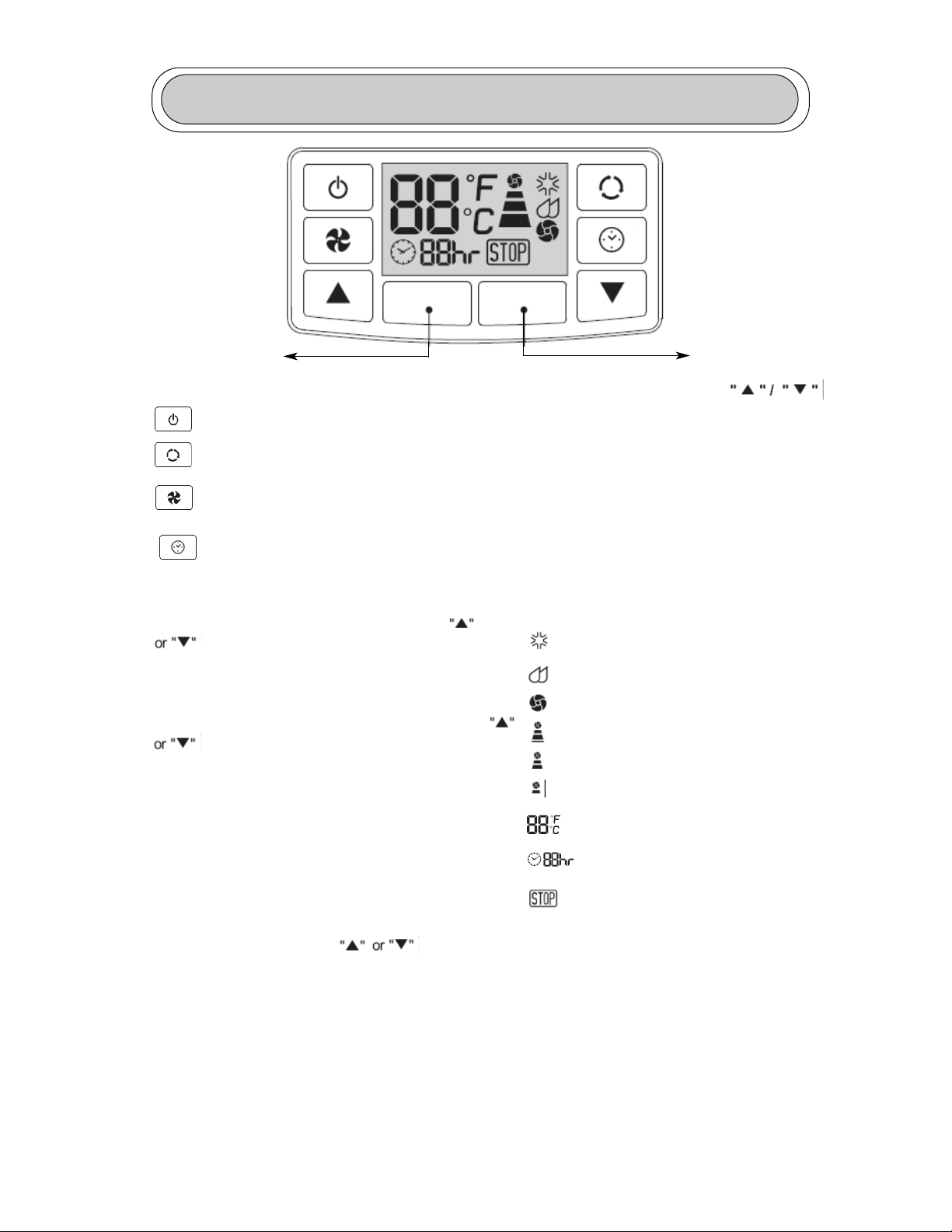
OPERATION- Features of the Control Panel
6
Warning Light
Receiving Sensor
KEY PAD FUNCTIONS
POWER SWITCH:Turns unit ON/OFF
MODE: Allows you to scroll through and
select desired operating mode.
FAN: Select from three different fan
settings; High, Medium, and Low.
AUTO-TIMER
AUTO-TIMER Adjust:
Auto off- With machine in running mode, press
timer button to set timer control. Press
buttons to select number of hours you
would like the unit to run before it automatically
shuts off.
Auto on- With machine in stand by mode,
press timer button to set timer control. Press
buttons to select number of hours before
the unit automatically starts running in air
conditionning mode.
NOTE: The time is adjustable between 1-24
hours.
TEMPERATURE Adjust:
• Used for adjusting the thermostat.
• The default display is room temperature.
• In cooling mode, when
button is pressed, the set temperature is
displayed and may be adjusted. After 15 seconds
the display will revert back to room temperature.
Temperature is only adjustable in cool mode.
Warning Light
Condensed water may accumulate in
the unit. If the internal tank becomes
full, the Warning signal in the LCD
Display will light up and the unit will not
operate until it has been drained.
LCD Display
Cooling Mode
Dehumidify Mode
Fan Only Mode
High Fan Speed
Medium Fan Speed
Low Fan Speed
Display Set Temperature
Display Timer Setting of Auto
Switch ON / OFF
Warning Light (the machine will
stop running)
NOTE: By pressing both
buttons at the same time for more
than 3 seconds, the display will
toggle between Celsius and
Fahrenheit.
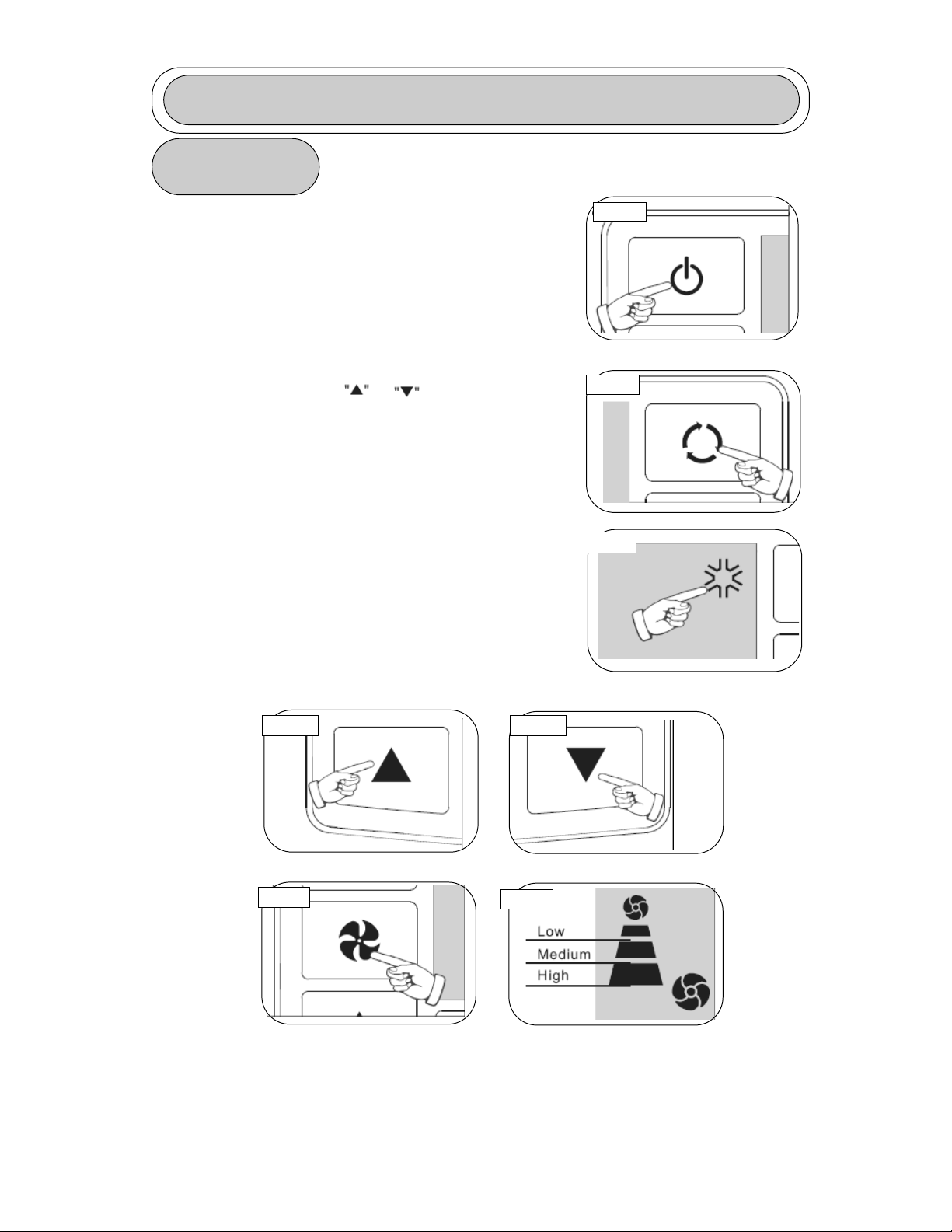
OPERATING INSTRUCTIONS
7
AIR
CONDITIONING
IMPORTANT: The exhaust hose must be properly vented
(outdoors) during air conditioning mode.
1) Press the POWER SWITCH key (Fig. A) to switch
on the unit, and the previous set temperature will
be shown in the temperature display area of the
control panel.
2) Press the MODE key (Fig. B) until the COOL
indicator light illuminates on the control panel
(Fig.C). Each depression of the MODE key will
advance to a different mode setting
(Cool-Dehumidifier-Fan-Heat-Auto)
3) Press the appropriate or buttons (Fig. D1
& D2) to select a suitable operating temperature
setting. Temperature settings are adjustable
between 16°C (61°F) to 32°C (89°F).
4) Press the FAN key (Fig. E) to select the desired
fan speed setting (Auto-High-Med.-Low). Your
selection will appear on the control panel (each
depression of the fan key will advance to a different
setting).
• Cooling stops automatically when the set
temperature is achieved. Cooling resumes when the
room temp. rises above the “set” temperature level.
Fig. A
Fig. B
Fig. C
Fig. D1 Fig. D2
Fig. E
Fig. F

OPERATING INSTRUCTIONS (cont’d)
8
DEHUMIDIFIER
Note: During dehumidifier mode, the exhaust hose
does not have to be vented outdoors.
1) Press the ON/OFF key pad to switch the unit on
(Fig. G)
2) Press the MODE key (Fig. H) until the DRY
indicator illuminates on the control panel (Fig.I).Each
press of the MODE key will advance to a different
mode setting (Cool-Dehumidifier-Fan-Heat-Auto).
IMPORTANT: There is no fan speed or temperature
adjustment during dehumidifier mode. The fan speed
is factory set for Low and the dehumidifier operates
continuously (non-stop) regardless of ambient
humidity level or set temperature.
FAN
NOTE: During Fan Mode, the exhaust hose
does not have to be vented outdoors.
1) Press the ON/OFF key pad to switch the unit on
(Fig. G).
2) Press the MODE key (Fig. H) until the FAN
indicator illuminates on the control panel (Fig. J).
Each press of the MODE key will advance to a
different mode setting (Cool-Dehumidifier-Fan-HeatAuto).
3) Press the FAN Key (Fig. K) to select the desired
FAN SPEED setting. Your selection will appear on
the control panel. Each press of the fan key will
advance to a different fan speed (High- Med- Low)
as shown in Fig. L.
Fig. J
Fig. H
Fig. G
Fig. I
Fig. K
Fig. L

OPERATING INSTRUCTIONS (cont’d)
AUTO-TIMER
The AUTO-TIMER feature offers a unique selection of multiple
choice, fully automatic on and/or off (start/stop) programs between
1-24 hours under any one mode of your Home Comfort unit.
The programs are as follows:
a) Auto-Off: Pre-select a time that will turn off the unit automatically (between 1-12hrs).
b) Auto-On: Pre-select a time that will turn on the unit automatically (between 1-12hrs).
c) Auto-On & Auto Off: Pre-select a time that will turn the unit ON / OFF automatically
at specified times (between 1-12hrs).
Note: These functions must be performed daily, as the program is automatically
canceled/erased after the program has ended.
9
REMOTE CONTROL
FEATURES
Control Buttons:
1) Power Switch
2) Mode
3) Fan Speed
4) On / Off Timer
5) Time / Temperature Set
• Used for adjusting the timer and
temperature.
• The default display on control panel is
room temperature.
• When
key is pressed in
cool mode, the set temperature is
displayed and may be adjusted. After 10
seconds the display will revert back to
room temperature.
• Timer setting is available from 1-24
hours by pressing the key
To operate the hand held remote control
you will require two “AAA” Alkaline
batteries (included).
Batteries should be replaced when:
a) No signal (beep) is heard when attempting to program the main unit.
b) The main unit does not respond to a command issued by the remote control.
Battery replacement:
1) Slide the rear cover on the remote in the direction of the arrow. Continue pulling (gently)
until the cover separates completely from the unit.
2) Insert (2) batteries (AAA) following the same orientation (polarity) depicted inside the
battery chamber (+ / -).
3) Re-install rear cover.
4) If the remote control will not be used for extended periods of time (vacations, etc.),
batteries should be removed.
The remote operates within a range of 8 meters (26 ft.) from the receiver located inside
the main unit. Any obstruction between the receiver and remote may cause signal
interference, limiting the ability to program the unit.
Notes:
1) Do not drop the remote control.
2) Do not place the remote control in a location exposed to direct sunlight.
3) The remote control should be placed about 1 meter or more away from TV, or any
electrical appliances.
This Class B digital apparatus complies with canadian ICES-003.

CARE AND MAINTENANCE
CAUTION: Before cleaning or servicing this unit, disconnect from any electrical supply outlet.
1) DO NOT use gasoline, benzene, thinner, or any other chemicals to clean this unit, as
these substances may cause damage to the finish and deformation of plastic parts.
2) Never attempt to clean the unit by pouring water directly over any of the surface areas, as
this will cause deterioration of electrical components and wiring insulation.
3) Unplug the unit.
4) Clean the unit by wiping off any dirt/dust with a soft damp cloth or vacuum cleaner, then
wipe dry with a dry soft cloth.
CAUTION: Always store the unit in vertical position. DO NOT put heavy objects on top of the
unit.
10
CLEANING
THE UNIT
CLEANING
THE AIR FILTER
If the air filter becomes clogged with dust/dirt, air
flow is restricted, which reduces cooling efficiency.
The air filter should be cleaned every two (2)
weeks. More frequent cleaning may be necessary
depending on indoor air quality.
NOTE: The air filter is located at the upper rear
side of the unit.
1) To remove the air filter: Pull the air filter cover
upward in the direction of the arrow (Fig.4) and
remove the air filter.
2) Dust/dirt clogged in the filter can be removed by
vacuum cleaning the soiled areas.
3) The filter can also be washed in lukewarm,
soapy water while rubbing it lightly with a brush. A
mild detergent (diswashing liquid) is recommended.
4) Rinse the filter well using clean water. Allow
time to dry before reinstalling into the unit.
5) Replace the air filter and cover.
6) Replacement air filter information is available by
contacting the Customer Service Department at:
1-800-26-
1-800-263-2629
CAUTION: Never operate this unit without the air filter in
place, as this may result in damage to the unit.
Fig. 4

TROUBLESHOOTING
PROBLEM POSSIBLE CAUSE SOLUTION
• Unit does not work
• Unit suddenly stops
during operation
• Unit runs intermittently
• Unit functions but the
room is not cooled
• Condensed water spills
out when moving the unit
• Power is out
• The plug is not plugged in
properly
• The full-tank indicator is ON; tank
is full
• Current leaking or pressing test
button on LCDI plug
• Indoor set temperature has been
reached
• The preset time is up
• The full-tank indicator is ON; tank
is full
• Malfunction
• Surrounding temperature is too
high/low
• Exhaust duct hose is blocked
• Window or door is open in room
• There is a heat source or too
many people in the room
• Air intake grill is clogged
• Filter is too dirty
• Temperature setting is too high
• The tank is nearly full
• Wait for power to return
• Plug in properly
• Remove drain water from
the drain tank
• Press the reset button
after resolving problem
• Reset the temperature
level
• Reset the timer
• Remove drain water from
the drain tank
• Contact your dealer
• This is normal
• Check the duct hose
• Close all windows/doors
• Move any heat sources
from room
• Clean air intake grill
• Replace the filter
• Lower temp. setting
• Remove drain plug on
rear bottom and drain out
water
11

LIMITED AIR CONDITIONER WARRANTY
This quality product is warranted to be free from manufacturer’s defects in material and workmanship, provided that the unit is used under the normal operating
conditions intended by the manufacturer.
This warranty is available only to the person to whom the unit was originally sold by Danby or by an authorized distributor of Danby, and is non-transferable.
TERMS OF WARRANTY
Plastic parts, are warranted for thirty (30) days only from purchase date, with no extensions provided.
First Two Years
During the first twenty four (24) months, any electrical parts of this product found to be defective, including any sealed system units, will
be repaired or replaced, at warrantor’s option, at no charge to the ORIGINAL purchaser.
To obtain
Danby reserves the right to limit the boundaries of “In Home Service” to the proximity of an Authorized Service Depot. Any appliance
Service
requiring service outside the limited boundaries of “In Home Service” ,it will be the consumer’s responsibility to transport the appliance
(at their own expense) to the original retailer (point of purchase) or a service depot for repair. Contact your dealer from whom your unit
was purchased, or contact your nearest authorized Danby service depot, where service must be performed by a qualified service
technician. If service is performed on the units by anyone other than an authorized service depot, or the unit is used for commercial
application, all obligations of Danby under this warranty shall be at an end.
EXCLUSIONS
Save as herein provided, Danby Products Limited (Canada) or Danby Products Inc. (U.S.A.), there are no other warranties, conditions, representations or
guarantees, express or implied, made or intended by Danby Products Limited or its authorized distributors and all other warranties, conditions, representations or
guarantees, including any warranties, conditions, representations or guarantees under any Sale of Goods Act or like legislation or statue is hereby expressly
excluded. Save as herein provided, Danby Products Limited (Canada) or Danby Products Inc. (U.S.A), shall not be responsible for any damages to persons or
property, including the unit itself, howsoever caused or any consequential damages arising from the malfunction of the unit and by the purchase of the unit, the
purchaser does hereby agree to indemnify and save harmless Danby Products Limited from any claim for damages to persons or property caused by the unit.
GENERAL PROVISIONS
No warranty or insurance herein contained or set out shall apply when damage or repair is caused by any of the following:
1) Power Failure.
2) Damage in transit or when moving the appliance.
3) Improper power supply such as low voltage, defective house wiring or inadequate fuses.
4) Accident, alteration, abuse or misuse of the appliance such as inadequate air circulation in the room or abnormal operating conditions,
(extremely high or low room temperature).
5) Use for commercial or industrial purposes.
6) Fire, water damage, theft, war, riot, hostility, acts of God such as hurricanes, floods etc.
7) Service calls resulting in customer education.
Proof of purchase date will be required for warranty claims; so, please retain bills of sale. In the event warranty service is required, present this document to our
AUTHORIZED SERVICE DEPOT.
Danby Products Limited
PO Box 1778, 5070 Whitelaw RD, Guelph, Ontario, Canada N1H 6Z9
Telephone: (519) 837-0920 FAX: (519) 837-0449
Danby Products Inc.
PO Box 669, 101 Bentley Court, Findlay, Ohio, U.S.A. 45840
Telephone: (419) 425-8627 FAX: (419) 425-8629
07/08
Warranty Service
In Home on Models 6,000 BTU or Greater

TABLE DES MATIÉRES
SPÉCIFICATIONS DE L’UNITÉ . . . . . . . . . . . . . . . . . . . . . 14
IDENTIFICATION DE PARTIE . . . . . . . . . . . . . . . . . . . . . . .15
CONSIGNES DE SÉCURITÉ IMPORTANT
Spécifications Électrique . . . . . . . . . . . . . . . . . . . . . . . . . . . 15
Suggestions pour économiseur d'énergie . . . . . . . . . . . . . . . . 16
INSTALLATION . . . . . . . . . . . . . . . . . . . . . . . . . . . . . . . . . . . . . 17
Installation de kit de fenêtre . . . . . . . . . . . . . . . . . . . . . . . . . . . 17
UTILISATION
Dispositifs du panneau de commande . . . . . . . . . . . . . . . . . . . . . 18
Climatisation . . . . . . . . . . . . . . . . . . . . . . . . . . . . . . . . . . . . . 19
Déshumidificateur . . . . . . . . . . . . . . . . . . . . . . . . . . . . . . . . . . . . . 20
Ventilateur . . . . . . . . . . . . . . . . . . . . . . . . . . . . . . . . . . . . . . . . . . . 20
Minuterie Automatique . . . . . . . . . . . . . . . . . . . . . . . . . . . . . . . . 21
Dispositifs à télécommande . . . . . . . . . . . . . . . . . . . . . . . . . . . 21
SOINS ET ENTRETIEN . . . . . . . . . . . . . . . . . . . . . . . . . . . 22
DÉPANNAGE . . . . . . . . . . . . . . . . . . . . . . . . . . . . . . . . . . . . . 23
Garantie . . . . . . . . . . . . . . . . . . . . . . . . . . . . . . . . . . . . . . . . . . . 24
13

BIENVENUE
Merci d’avoir choisi un appareil Danby qui vous fournira ainsi qu’à votre famille, le confort au
foyer, à la maison, au chalet ou au bureau. Ce manuel d’utilisation vous offre des
renseignements pratiques pour le soin et l’entretien de votre nouvel appareil. Un appareil
Danby bien entretenu vous fournira plusieurs années de service sans ennui.
Veuillez prendre quelques moments pour lire attentivement toutes les directives pour vous
renseigner et vous familiariser avec tous les aspects du fonctionnement de votre appareil.
Votre climatiseur portable Danby est un appareil d’échange et de traitement de l’air à
fonctions multiples. Sa conception vous offre les fonctions suivantes: la climatisation, la
déshumidification et la ventilation indépendante. Chacun des modes est équipé d’une
capacité de balayage de l’air par oscillation. Cet appareil peut être aisément déplacé d’une
pièce à l’autre de la maison et il est installé en quelques minutes seulement. Imaginez la
commodité du confort au foyer 3 saisons à portée de la main, en tout temps, en tout lieu.
Pour la référence aisée, nous vous suggérons de joindre une copie de votre reçu de caisse
et/ou facture d’achat à cette page, et d’inscrire les renseignements suivants qui sont trouvés
sur la plaque d’identification du fabricant. Celle-ci est située sur le panneau arrière de
l’appareil.
Numéro de modèle:
Numéro de série :
Date d’achat :
Ces renseignements seront requis si le service est demandé et/ou si vous désirez obtenir des
renseignements supplémentaires. Pour consulter un Représentant du service à la clientèle,
composez le NUMÉRO D’APPEL SANS FRAIS suivant:
1-800-26(1-800-263-2629)
SPÉCIFICATIONS DE L’UNITÉ
REMARQUE: La recherche ensuit toujours des améliorations. Par conséquent, ces
informations et spécifications peuvent changer sans préavis.
14
Modèle DPAC9009
Source d’alimentation 115V-60Hz
Niveau de bruit 48.5 dB
Vitesse de ventilateur 3
Capacité de climatisation 9000BTU
Réfrigérant R410A
Unit Weight 27.2 kg (60lbs)
Airflow CFM Haut/Moyenne/Bas 342 / 318 / 288
Dimensions (lgr) x (pfdr) x (htr)(pouces) 17.2x 15.3x 30.5
Dimensions (lgr) x (pfdr) x (htr) (mm) 475 / 460 / 870
Télécommande Oui
Horologe Non
Minuterie automatique Oui

TABLEAU 2
Types de fusibles et de réceptacles
Tension nominale 125
Ampères 13
Prise de courant
Intensité de fusible 15
Fusible temporisé Type fiche
(ou disjoncteur de circuit)
IDENTIFICATION DE PARTIE
CONSIGNES DE SÉCURITÉ IMPORTANT
LISEZ TOUTE L'INFORMATION DE SÉCURITÉ AVANT UTILISATION
1) Vérifier l’alimentation de courant disponible et
résoudre tout problème AVANT l’installation et
l’usage de cette unité. Le câblage doit être
conforme aux codes local et national de
l’électricité avec l’installation par un électricien
qualifé. Pour toutes questions concernant les
directives qui suivent, communiquer avec un
électricien qualifé.
2) Cet appareil débite 10 ampères tel qu’indiqué
sur la plaque d’identification en mode de
refroidissement et il peut être utilisé avec tout
réceptacle domestique de 13 ampères d’usage
général, correctement câblé et mis à la terre.
3) Pour votre sécurité et votre protection, cette
unité est mise à la terre par la fiche du cordon
d’alimentation quand elle est branchée sur une
prise de courant adaptée. Si vous n’êtes pas
certain que les prises de courant de votre
domicile sont correctement mises à la terre,
consultez un électricien qualifié.
4) NE PAS UTILISER LES ADAPTATEURS DE
FICHE OU LES CORDES DE RALLONGE
AVEC CETTE UNITÉ. S’il est nécessaire d’en
utiliser une, utiliser une corde de rallonge
approuvée pour l’usage avec les climatiseurs
seulement (disponible dans la plupart des
quincailleries locales).
5) Pour éviter la possibilité de blessure corporelle,
toujours débrancher l’alimentation de courant à
l’unité avant d’entreprendre l’installation et/ou le
service.
SPÉCIFICATIONS
ÉLECTRIQUES
TABLEAU 1
Circuit de distribution individuel suggéré
Ampères de plaque d’identification Calibre de fil AWG*
10 16
AWG – American Wire Gauge (Calibre de fil américain)
*Basé sur le fil en cuivre à une température nominale de 600C
MISE EN GARDE: Ne jamais laisser
cet appareil en marche dans un endroit
fermé oú des personnes ou animaux qui ne
peuvent pas réagir à une défectuosité de
l’appareil se trouvent. Un appareil en panne
peut occasionner la surchauffe extrême de
cet appareil ou la mort dans un espace
fermé non surveillié.
15
Échappement d’air
Affichage
ACL
Panneau
Frontal
Roues
Poignées
Filtre à air
Entrée
d’air
Sortie
d’air
Couvercle
Câble
électrique
Drain à eau
Entrée
d’air

CORDON
D’ALIMENTATION
Le cordon d’alimentation fourni avec cet air conditionné contient un
dispositif qui détecte les dommages au cordon. Pour tester si votre cordon
d’alimentation fonctionne adéquatement, vous devez faire ce qui suit :
CONSIGNES DE SÉCURITÉ IMPORTANT
SUGGESTIONS
POUR L’ÉCONOMIE DE
L’ÉNERGIE
Votre appareil ménager Danby est conçu pour l’efficacité en
économie de l’énergie. Pour le rendement maximal, observer les
recommandations qui suivent.
1) Choisir un réglage du thermostat qui
répond à vos besoins de confort et le
laisser au réglage choisi.
2) Le filtre à air est très efficace pour
éliminer les particules qui flottent dans l’air.
Conserver le filtre à air propre en tout
temps.
3) Utiliser des draperies, des rideaux ou
des stores pour prévenir la pénétration et le
réchauffement de la pièce par les rayons
directs du soleil, mais ne pas permettre la
restriction de la circulation d’air autour de
l’unité par les draperies ou les rideaux.
4) Activer votre climatiseur avant que la
température de l’air extérieur ne soit très
chaude et inconfortable. Ceci préviendra une
période initiale d’inconfort avant que l’unité ne
puisse refroidir la pièce. L’usage de la
caractéristique de MINUTERIE programmable
d’arrêt et de mise en marche automatique
représente un important avantage à cet effet
si elle est utilisée à pleine capacité.
5) Quand les températures externes sont
suffisamment froides, placer le climatiseur
hors de service et utiliser le MODE DE
VENTILATEUR à la position HAUTE,
MOYENNE ou BAS. Ceci fait circuler l’air à
l’intérieur de la pièce pour fournir un certain
confort de climatisation en utilisant moins
d’électricité.
Le cordon d’alimentation fourni avec cet air
conditionné contient un dispositif de détection
de fuite de courant conçu pour réduire les
risques d’incendie. Veuillez vous référer à la
section ‘Cordon d’alimentation’ pour plus de
détails. Advenant le cas que le cordon d’alimentation soit endommagé, il ne peut être réparé et
doit être remplacé avec un nouveau cordon
provenant du fabricant.
• Ce dispositif ne devrait être utilisé sous
aucune circonstance pour mettre en marche ou
arrêter l’unité.
• Le bouton de ‘RESET’ doit toujours être
enfoncé pour un fonctionnement normal.
• Le cordon d’alimentation doit être remplacé s’il
ne se réinitialise pas lorsque le bouton ‘TEST’
est enfoncé.
1) Branchez le cordon d’alimentation à une
prise d’alimentation électrique.
2) Le cordon d’alimentation possède deux
boutons situés sur la tête de la fiche. L’un des
boutons est identifié par ‘TEST’ et l’autre
bouton par ‘RESET’. Appuyez sur le bouton
‘TEST’ et vous entendrez un déclic puisque le
bouton ‘RESET’ sera ressorti.
3) Appuyez sur le bouton ‘RESET' et vous
entendrez un déclic lorsque le bouton sera
enfoncé.
4) Le cordon d’alimentation est maintenant
alimenté et il fournit de l’électricité à l’air
conditionné. (Sur certains produits, ceci sera
aussi indiqué par une lumière sur la tête de la
fiche).
18

INSTALLATION
KIT DE FENÊTRE
Mode Climatisation Seulement
Votre kit de fenêtre a été conçu pour l’adaptation à la plupart des fenêtres verticales et/ou
horizontales et portes patio standard. Les applications de porte patio sont limitées aux
portes atteignant une hauteur maximale de 80 po (203 cm). Deux vis de blocage sont
fournies pour joindre ensemble chaque section coulissante.
1) Choisissez un endroit approprié, celui est sûr d'avoir accès à une sortie électrique.
2) Installez le tuyau flexible sur le dos de l'unité. Insérez le collier de tuyau sur l'ouverture
d'échappement et tordez pour fermer en place.
3) Installez le kit réglable de glisseur de fenêtre comme nécessaire (voir la fig. 3a & 3b).
4) Installez l'autre extrémité du tuyau d'échappement flexible sur l'adapteur d'échappement
de fenêtre.
5) Installez l'adapteur d'échappement de fenêtre sur l'ouverture dans la section de glisseur,
en veillant que les sections de glisseur de fenêtre sont bloquées.
6) Branchez l'unité à une sortie électrique au sol par 115V/60Hz.
20
Kit de coulisse de fenêtre:
Min.: 28
1
/3po (72cm)
Max.: 80” (203cm)
Kit de coulisse de
fenêtre:
Min.: 28
1
/3po (72cm)
Max.: 80” (203cm)
Fenêtre Horizontale
Fenêtre
Verticale
INSTALLATION
Tuyay d’echappement flexible (13cm) & bec
connecteur d’échappement (2 mcx)... de 17
7
/10
(45cm) jusqu’à 53 1/6” (135cm)
Tuyay d’echappement flexible (11cm) & bec
connecteur d’échappement (2 mcx)... de 15
3
/4”(45cm) jusqu’à 51 1/5” (135cm)
Ensemble de portes-fenêtre coulissantes (3
mrc)... de 28
1
/3”(72cm) jusqu’à 80” (203cm)
Ferrures..... (2 mcx)
Vis......(12 mcx)
NOTE : Le kit d'échappement/fenêtre doit être
installé à tout moment quand l'unité fonctionne
sous le mode de CLIMATISATION.
Il devrait y avoir au moins 11.8 dégagements (de
30cm) entre l'unité et tous les autres objets ou
fondations, et devrait être installé sur une surface de
niveau. L'unité ne doit pas être exhalée extérieur
opération pendant de déshydratation ou de
ventilateur seulement mode.
L’arriére du panneau
de fenêtre
Tube de raccords
Fig. 2
Les instructions d’assemblage pour
l’ensemble d’adapteurs de fenêtre- Fig. 2
1) Insérez le tube de raccord à travers l’arriére du
panneau de fenêtre.
2) Fixez chaque tube de raccord avec quatre vis
à travers l’avant du panneau de fenêtre.
3) Insérez les extensions de panneau de fenêtre
dans le panneau de fenêtre. Serrez légèrement
les vis dans le panneau de fenêtre afin de
maintenir les extensions en place.
RISQUE DE CHOC ÉLECTRIQUE: Pour éviter la possibilité de blessures
corporelles, débrancher l’alimentation de courant à l’unité avant
d’entreprendre l’installation ou le service.
Fig. 1
Accessoires D’Installation
Tuyau d’échappement
flexible
Connecteur de la
tuyére de
Ferrure
Ensemble de glissiéres de fenêtre:
28 1/3” (72cm)- 80” (203cm)
Vis
sortie
Fig. 3a
Fig. 3b

NOTE : Pressez tous les boutons
en même temps pendant
plus de 3 secondes, et l'affichage
alterneront Celsius et Fahrenheit.
FONCTIONNEMENT - Caractéristique du panneau de commande
21
Lampe témoin
Détecteur récepteur
FONCTIONS DE BLOC NUMÉRIQUE
INTERRUPTEUR D’ALIMENTATION: Permet
de mettre l’appareil en Marche/Arrêt
MODE: Vous permet fair défiler et de
sélectionner le mode de fonctionnement désiré
VENTILATEUR: Sélectionnez à partir de trois
réglages de ventilateur différent; Haut,
Moyenne, et Bas.
MINUTERIE AUTOMATIQUE
La MINUTERIE AUTOMATIQUE s'ajustent :
Arrêt automatique- Avec la machine en mode
courant, appuyez sur le bouton de temporisateur
pour placer la commande de temporisateur.
Appuyez sur les boutons pour choisir
le nombre d'heures où vous voudriez que l'unité
coure avant qu'elle ait automatiquement coupé.
Marche automatique- Avec la machine tenezvous prêt dedans le mode, appuient sur le
bouton de temporisateur pour placer la
commande de temporisateur. Appuyez sur les
boutons pour choisir le nombre
d'heures avant que l'unité commence
automatiquement à fonctionner en mode
conditionning d'air.
NOTE : Le temps est réglable entre 1-24
heures.
La TEMPÉRATURE s'ajustent :
• Utilisé pour ajuster le thermostat.
• L'affichage de défaut est température ambiante.
• En mode de refroidissement, quand le bouton
est appuyé sur, la température d'ensemble est
montrée et peut être ajustée. Après 15 secondes
l'affichage retournera de nouveau à la
température ambiante. La température est
seulement réglable en mode frais.
LUMIÈRE D'AVERTISSEMENT
L'eau condensée peut s'accumuler dans
l'unité. Si le réservoir interne devient
complètement, le signal d'alarme dans
l'affichage ACL s'allumera et l'unité ne
fonctionnera pas jusqu'à ce qu'elle ait été
vidangée.
Affichage ACL
Mode de refroidissement
Mode déshumidificateur
Mode de ventilateur seulement
Vitesse de ventilateur Haut
Vitesse de ventilateur Moyenne
Vitesse de ventilateur Bas
L'affichage de la température
programmé
Affichage de la minuterie
réglage de l’interrupteur
automatique marche/arrêt
Lampe témoin (l’appareil
arrêtera de fonctionner)
ou
ou

FONCTIONNEMENT
DU
CLIMATISEUR
REMARQUE: Le tuyau flexible pour l’échappement d’air
doivent être installés pour le fonctionnement en mode de
climatisation
1) Appuyer sur la touche INTERRUPTEUR (Fig. A)
pour activer l’unité et le réglage précédent du
température sera montrée dans l’affichage de la
température sur le panneau de commande.
2) Appuyer sur la touche MODE (Fig. B) jusqu’a
l’indicateur du mode Frais illumine sur le panneau
du commande (Fig. C). Chaque dépression sur la
touche MODE avancera l’affichage à un réglage
de mode différent (Frais-Sec-Ventilateur).
3) Appuyer sur le touche augmenter ou diminuer
(RÉGLAGE DE TEMPÉRATURE) (Fig. D) pour
choisir un réglage de température appropriée. Les
réglages de température sont réglables entre 17°C
(62.6°F) à 30°C (86°F).
4) Appuyer sur la touche VENTILATEUR (Fig. E)
pour choisir le réglage de la vitesse désirée du
ventilateur (Haut-Moyenne-Basse). Votre sélection
apparaîtra sur le panneau de commande (chaque
dépression de la touche du ventilateur avancera
l’indicateur au prochain réglage).
• La climatisation cesse automatiquement
quand la température réglée est atteinte. La
climatisation résume quand la température de
la pièce s’élève au-dessus de la température
réglée.
22
Fig. A
Fig. B
Fig. C

FONCTIONNEMENT (suite)
23
DÉSHUMIDIFICATEUR
REMARQUE: L’installation du tuyau flexible pour
l’echappement d’air n’est pas requise pour le
fonctionnement en mode de Déshumidification.
1) Appuyer sur la touche INTERRUPTEUR pour
activer l’unité (Fig. G).
2) Appuyer sur la touche MODE (Fig. H) jusqu’à
l’affichage du symbole Déshumidification sur le
panneau de commande (Fig. I). Chaque dépression
sur la touche MODE avancera l’affichage à un
réglage de mode différent (Frais-Sec-Ventilateur).
Important: Il n’y a aucun ajustement pour la vitesse
du ventilateur ou la température pendant le mode de
déshumidificateur. La vitesse de ventilateur est
pré-réglée (haute) et le déshumidificateur fonctionne
sans interruption indépendamment des niveaux
ambiants d’humidité ou réglage du température.
FAN
REMARQUE: L’installation du tuyau flexible
pour l’échappement d’air n’est pas requise
pour le fonctionnement en mode de
ventilation seulement.
1) Appuyer sur la touche INTERRUPTEUR pour
activer l’unité (Fig. G).
2) Appuyer sur la touche MODE (Fig. H) jusqu’à
l’affichage du symbole VENTILATEUR sur le |
panneau de commande (Fig. J). Chaque dépression
sur la touche MODE avancera l’affichage à un
réglage de mode différent (Frais-Sec-Ventilateur).
3) Appuyer sur la touche VENTILATEUR (Fig. K)
pour choisir la VITESSE DE VENTILATEUR désirée.
Votre réglage apparaitra sur le panneau du
commande. Chaque dépression sur la touche
VENTILATEUR avancera l’affichage à un réglage de
vitesse différente (Haut-Moyenne-Bas) (Fig. L)
Fig. J
Fig. H
Fig. G
Fig. I
Fig. K
Fig. L
Basse
Moyenne
Haut

FONCTIONNEMENT (suite)
MINUTERIE
AUTOMATIQUE
La caractéristique de la MINUTERIE AUTOMATIQUE offre une sélection
unique de plusieurs choix, entièrement automatique et/ou programmes
d'arrêt (démarrage/arrêt) entre 1 à 12 heures dans tous les modes de
votre Unité de confort à la maison.
Les programmes sont comme suit:
a) Arrêt automatique : Sélectionnez une heure à laquelle l'unité s'arrêtera automatiquement
(entre 1 à 12 heures).
b) Marche automatique Sélectionnez une heure à laquelle l'unité se mettra en marche
automatiquement (entre 1 à 12 heures).
c) Arrêt et marche automatique : Sélectionnez une heure à laquelle l'unité se mettra en marche
et s'arrêtera automatiquement (entre 1 à 12 heures).
Remarque : Ces fonctions doivent être réglées quotidiennement puisque le programme est
automatiquement annulé/effacé après que le programme est terminé.
25
CARACTÉRISTIQUES DE
TÉLÉCOMMANDE
Boutons De Commande:
1) Commutateur de courant
2) Mode
3) Vitesse du Ventilateur
4) Minuterie Marche/Arrêt (On/Off)
5) Réglage de l'heure/température
• Utilisé pour régler la minuterie et la
température.
• La température ambiante est l'affichage par
défaut sur le panneau de commande.
• Lorsque vous appuyez sur le bouton
en mode climatisation, la température réglée est
affichée et peut être ajustée. Après 10 secondes
l’affichage revient à la température ambiante.
• Le réglage de la minuterie disponible est de 1 à
24 heures en appuyant sur la touche
Deux piles alcalines «AAA» sont requises pour le
fonctionnement de la télécommande (incluses).
Les piles devraient être remplacées quand:
1) Glisser le couvercle du compartiment des piles à l’arriére de la télécommande dans le sens
de la flèche. Tirer délicatement jusqu’à ce que le couvercle se sépare complètement de l’unité.
2) Insèrer deux (2) piles (AAA) en observant la polarité indiquée dans le compartiment des
piles (+ / - ).
3) Réinstaller le couvercle.
4) Si la télécommande ne sera pas utilisée pour des périodes prolongées (vacances, etc.), les
piles devraient étre retirées de la télécommande.
La télécommande fonctionnera en dedans d’une distance de 8 mètres (26pi.) du récepteur
situé à l’interieur de l’unité principale. Toute obstruction entre le récepteur et la télécommande
pourrait causer une interférence au signal, ce qui limiterait la capacité de programmation de
l’unité principale.
Remarque: Le température est affiché sur l’affichage électronique en échelle Celcius
seulement.
Notes
1) Ne laissez pas tomber la télécommande.
2) Ne placez pas la télécommande directement sous les rayons du soleil.
3) La télécommande devrait être placée à 1 mètre ou plus de la télévision ou d’autre type
d’appareil électrique.
Cet appareil numérique de classe B est conforme au norme Canadienne ICES-003.
ou
ou

SOINS ET ENTRETIEN
MISE EN GARDE: Avant de nettoyer ou de faire le service sur cette unité, il est
recommandé de débrancher le cordon d’alimentation de la prise de courant électrique.
1) NE PAS utliser d’essence, de benzène, de diluant ou tous autres produits chimiques
pour nettoyer cette unité. Ces substances pourraient causer des dommages au fini et
une déformation des pièces en plastique.
2) NE JAMAIS tenter de nettoyer l’unité en versant de l’eau directement dur l’une ou
l’autre des surfaces car ceci causera une détérioration des pièces électriques et de
l’isolation des fils.
NETTOYAGE
DE L'UNITÉ
NETTOYAGE DES
FILTRES À AIR
Si les filtres à air devient bloqué par la poussière et/ou
la saleté, une restriction de la circulation d’air se
produira et le rendement de climatisation sera réduit.
Les filtres à air devrait être nettoyé aux deux (2)
semaines. Le nettoyage plus fréquent pourrait être
nécessaire selon la qualité de l’air interne.
REMARQUE: Le filtre à air est situé à la partie
supérieure arrière de l’unité.
1) Pour enlever le filtre à air : Tirez la couverture de
filtre à air vers le haut dans la direction de la flèche
(Fig.4) et enlevez le filtre à air.
2) La poussière/saleté a obstrué dans le filtre peut être
enlevée par le vide nettoyant les secteurs salis.
3) Le filtre peut également être lavé dans l'eau tiède et
savonneuse tout en la frottant légèrement avec une
brosse. Un détergent doux (liquide de vaisselle) est
recommandé.
4) Rincez le filtre bien utilisant l'eau propre. Accordez
l'heure de sécher avant la réinstallation dans l'unité.
5) Remplacez le filtre à air et le couvrez.
6) L'information de filtre à air de remplacement est
disponible en entrant en contact avec le département
de service à la clientèle à :
1-800-26-
(1-800-263-2629)
MISE EN GARDE: Ne jamais utiliser l’unité sans le
filtre à air en position. Ceci pourrait causer des
dommages à l’unité.
26
Fig. 4

DÉPANNAGE
PROBLEME CAUSE PROBABLE SOLUTION
• L'unité ne fonctionne pas
• L'unité arrête
soudainement durant son
fonctionnement
• L'unité fonctionne de
façon intermittente
• L'unité fonctionne, mais la
pièce n'est pas refroidie
• De l'eau condensée
s'égoutte lors du
déplacement de l'unité
• Il n'y a pas d'alimentation
• La fiche n'est pas branchée
adéquatement
• L'indicateur du réservoir plein est
en MARCHE; le réservoir est plein
• Fuite actuelle ou appuie sur le
bouton de test de la fiche LCDI
• La température intérieure réglée a
été atteinte
• Le temps réglé est terminé
• L'indicateur du réservoir plein est
en MARCHE; le réservoir est plein
• Défaillance
• La température environnante est
trop élevée/basse
• Le tuyau d'échappement est
bloqué
• La fenêtre ou la porte de la pièce est
ouverte
• Il y a une source de chaleur ou trop de
gens dans la pièce
• La grille de prise d'air est obstruée
• Le filtre est trop sale
• Le réglage de la température est trop
élevé
• Le réservoir est pratiquement
plein
• Attendez que
l'alimentation revienne
• Branchez adéquatement
• Enlevez l'eau du drain du
réservoir du drain
• Appuyez sur le bouton de
réinitialisation après avoir
résolu le problème
• Réinitilisez le niveau de
la température
• Réinitialisez la minuterie
• Enlevez l'eau du drain du
réservoir du drain
• Contactez votre marchand
• Ceci est tout à fait normal
• Vérifiez le tuyau
d'échappement
• Fermez toutes les fenêtres/portes
• Enlevez toute source de
chaleur de la pièce
• Nettoyez la grille de prise d'air
• Remplacez le filtre
• Abaissez le réglage de la
température
• Enlevez le bouchon du
drain au bas à l'arrière et
videz l'eau
27

GARANTIE LIMITÉE DE CLIMATISEUR
Cet appareil de qualité est garantie exempt de tout vice de matière première et de fabrication, s’il est utilisé dans les conditions normales recommandées par
le fabricant.
Cette garantie n’est offerte qu’à l’acheteur initial de l’appareil vendu par Danby ou par l’un des ses distributeurs agréés et elle ne peut être transférée.
CONDITIONS
Les pièces en plastique sont garanties pour trente (30) jours seulement à partir de la date de l’achat, sans aucune prolongation prévue.
Première 24 Mois
Pendant les première vingt quatre (24) mois, toutes pièces électriques de ce produit s’avèrent défectueuses, y compris les unités ayant
des systèmes obturés, seront réparées ou remplacées, selon le choix du garant, sans frais à l’acheteur INITIAL.
Pour bénéficier du
Danby réserve le droit de limiter le rayon du “Service au domicile” selon la proximité d’un dépot de service autorisé. Le client sera
service sous garantie
responsable pour le transport et tous les frais d’expédition de tout appareil exigeant le service en dehors des limites du “Service au domicile” au dépot de service autorisé le plus proche. S’adresser au détaillant qui a vendu l’appareil, ou à la station technique agréée de
service la plus proche, où les réparations doivent être effectuées par un technicien qualifié. Si les réparations sont effectuées par
quiconque autre que la station de service agréée où à des fins commerciales, toutes les obligations de Danby en vertu de cette garantie
seront nulles et non avenues.
EXCLUSIONS
En vertu de la présente, il n’existe aucune autre garantie, condition ou représentation, qu’elle soit exprimée ou tacite, de façon manifeste ou intentionnelle, par
Danby Products Limitée (Canada) ou Danby Products Inc. (E.- U. d’A.) ou ses distributeurs agréés. De même, sont exclues toutes les autres garanties, conditions
ou représentations, y compris les garanties, conditions ou représentations en vertu de toute loi régissant la vente de produits ou de toute autre législation ou
règlement semblables.
En vertu de la présente, Danby Products Limitée (Canada) ou Danby Products Inc. (E.- U. d’A.) ne peut être tenue responsable en cas de blessures corporelles
ou des dégâts matériels, y compris à l’appareil, quelle qu’en soit les causes. Danby ne peut pas être tenue responsable des dommages indirects dus au fonctionnement défectueux de l’appareil. En achetant l’appareil, l’acheteur accepte de mettre à couvert et de dégager Danby Products Limitée de toute responsabilité en
cas de réclamation pour toute blessure corporelle ou tout dégât matériel causé par cet appareil.
CONDITIONS GÉNÉRALES
La garantie ou assurance ci-dessus ne s’applique pas si les dégâts ou réparations sont dus aux cas suivants:
1) Panne de courant;
2) Dommage subis pendant le transport ou le déplacement de l’appareil;
3) Alimentation électrique incorrecte (tension faible, câblage défectueux, fusibles incorrects);
4) Accident, modification, emploi abusif ou incorrect de l’appareil;
5) Utilisation dans un but commercial ou industriel;
6) Incendie, dommage causés par l’eau, vol, guerre, émeute, hostilités, cas de force majeure (ouragan, inondation, etc.);
7) Visites d’un technicien pour expliquer le fonctionnement de l’appareil au propriétaire.
Une preuve d’achat doit être présentée pour toute demande de réparation sous garantie. Prière de garder le reçu. Pour faire honorer la garantie, présenter ce
document à la station technique agréée ou s’adresser à:
Danby Products Limited
PO Box 1778, 5070 Whitelaw RD, Guelph, Ontario, Canada N1H 6Z9
Telephone: (519) 837-0920 FAX: (519) 837-0449
Danby Products Inc.
PO Box 669, 101 Bentley Court, Findlay, Ohio, U.S.A. 45840
Telephone: (419) 425-8627 FAX: (419) 425-8629
07/08
Service sous-garantie
Service au domicile sur modèles 6.000 Btu ou plus grands.

Model • Modèledelo
DPAC9009
For service, contact your
nearest service depot or call:
1-800-26-
(1-800-263-2629)
to recommend a depot in your
area.
Pour obtenir le service,
consultez votre centre de
service le plus rapproché ou
composez le:
1-800-26-
(1-800-263-2629)
vous recommendera un
centre régional.
Portable Air Conditioner
The model number can be found on the serial plate
located on the back panel of the unit.
All repair parts available for purchase or special order
when you visit your nearest service depot. To request
service and/or the location of the service depot nearest
you, call the TOLL FREE NUMBER.
When requesting service or ordering parts, always provide
the following information:
• Product Type
• Model Number
• Part Number
• Part Description
Climatiseur Portatif
Le numéro de modèle se trouve sur la plaque
d'information sur le panneau arrière de l’appareil.
Toutes les pièces de rechange ou commandes spéciales
sont disponibles à votre centre de service régional
autorisé.
Pour obtenir le service et/ou la localité de votre centre de
service régional, signalez le NUMÉRO D’APPEL SANS
FRAIS. Ayez les renseignements suivants à la portée de la
main lors de la commande de pièce ou service :
• Type de produit
• Numéro de modèle
• Numéro de pièce
• Description de la pièce
Printed in China (P.R.C.)
Danby Products Ltd, PO Box 1778, Guelph, Ontario Canada N1H 6Z9
Danby Products Inc, PO Box 669, Findlay, Ohio USA 45839-0669
 Loading...