

Daikin RXYSQ4T8VB(*), RXYSQ5T8VB(*), RXYSQ6T8VB(*), RXYSQ4T8YB(*), RXYSQ5T8YB(*) Installer reference guide
...
Installer and user reference guide
VRV IV-S system air conditioner
RXYSQ4T8VB(*)
RXYSQ5T8VB(*)
RXYSQ6T8VB(*)
RXYSQ4T8YB(*)
RXYSQ5T8YB(*)
RXYSQ6T8YB(*)

Table of contents
Table of contents
1 About the documentation 6
1.1 About this document ...................................................................................................................................................... 6
1.2 Meaning of warnings and symbols................................................................................................................................. 6
2 General safety precautions 8
2.1 For the installer............................................................................................................................................................... 8
2.1.1 General ........................................................................................................................................................... 8
2.1.2 Installation site ............................................................................................................................................... 9
2.1.3 Refrigerant — in case of R410A or R32.......................................................................................................... 9
2.1.4 Electrical ......................................................................................................................................................... 11
3 Specific installer safety instructions 14
For the user 17
4 User safety instructions 18
4.1 General............................................................................................................................................................................ 18
4.2 Instructions for safe operation ....................................................................................................................................... 19
5 About the system 22
5.1 System layout.................................................................................................................................................................. 22
6 User interface 24
7 Before operation 25
8 Operation 26
8.1 Operation range.............................................................................................................................................................. 26
8.2 Operating the system ..................................................................................................................................................... 26
8.2.1 About operating the system........................................................................................................................... 26
8.2.2 About cooling, heating, fan only, and automatic operation ......................................................................... 27
8.2.3 About the heating operation.......................................................................................................................... 27
8.2.4 To operate the system (WITHOUT cool/heat changeover remote control switch)...................................... 27
8.2.5 To operate the system (WITH cool/heat changeover remote control switch) ............................................. 28
8.3 Using the dry program.................................................................................................................................................... 29
8.3.1 About the dry program................................................................................................................................... 29
8.3.2 To use the dry program (WITHOUT cool/heat changeover remote control switch) .................................... 29
8.3.3 To use the dry program (WITH cool/heat changeover remote control switch) ........................................... 29
8.4 Adjusting the air flow direction ...................................................................................................................................... 30
8.4.1 About the air flow flap.................................................................................................................................... 30
8.5 Setting the master user interface................................................................................................................................... 31
8.5.1 About setting the master user interface........................................................................................................ 31
8.5.2 To designate the master user interface ......................................................................................................... 31
9 Energy saving and optimum operation 32
9.1 Available main operation methods ................................................................................................................................ 32
9.2 Available comfort settings .............................................................................................................................................. 33
10 Maintenance and service 34
10.1 Maintenance after a long stop period............................................................................................................................ 34
10.2 Maintenance before a long stop period......................................................................................................................... 35
10.3 About the refrigerant...................................................................................................................................................... 35
10.4 After-sales service and warranty .................................................................................................................................... 35
10.4.1 Warranty period............................................................................................................................................. 35
10.4.2 Recommended maintenance and inspection................................................................................................ 36
10.4.3 Recommended maintenance and inspection cycles ..................................................................................... 36
10.4.4 Shortened maintenance and replacement cycles......................................................................................... 37
Installer and user reference guide
2
11 Troubleshooting 38
11.1 Error codes: Overview .................................................................................................................................................... 39
11.2 Symptoms that are NOT system malfunctions............................................................................................................... 41
11.2.1 Symptom: The system does not operate....................................................................................................... 41
11.2.2 Symptom: Cool/Heat cannot be changed over ............................................................................................. 42
11.2.3 Symptom: Fan operation is possible, but cooling and heating do not work ................................................ 42
11.2.4 Symptom: The fan speed does not correspond to the setting...................................................................... 42
11.2.5 Symptom: The fan direction does not correspond to the setting................................................................. 42
RXYSQ4~6T8V/YB
VRV IV-S system air conditioner
4P482277-1B – 2020.10

Table of contents
11.2.6 Symptom: White mist comes out of a unit (Indoor unit) .............................................................................. 42
11.2.7 Symptom: White mist comes out of a unit (Indoor unit, outdoor unit)........................................................ 42
11.2.8 Symptom: The user interface reads "U4" or "U5" and stops, but then restarts after a few minutes.......... 43
11.2.9 Symptom: Noise of air conditioners (Indoor unit)......................................................................................... 43
11.2.10 Symptom: Noise of air conditioners (Indoor unit, outdoor unit) .................................................................. 43
11.2.11 Symptom: Noise of air conditioners (Outdoor unit)...................................................................................... 43
11.2.12 Symptom: Dust comes out of the unit........................................................................................................... 43
11.2.13 Symptom: The units can give off odours ....................................................................................................... 43
11.2.14 Symptom: The outdoor unit fan does not spin.............................................................................................. 43
11.2.15 Symptom: The compressor in the outdoor unit does not stop after a short heating operation ................. 44
11.2.16 Symptom: The inside of an outdoor unit is warm even when the unit has stopped.................................... 44
11.2.17 Symptom: Hot air can be felt when the indoor unit is stopped.................................................................... 44
12 Relocation 45
13 Disposal 46
14 Technical data 47
14.1 Information requirements for Eco Design...................................................................................................................... 47
For the installer 48
15 About the box 49
15.1 About LOOP BY DAIKIN ................................................................................................................................................... 49
15.2 Overview: About the box ................................................................................................................................................ 49
15.3 Outdoor unit ................................................................................................................................................................... 50
15.3.1 To unpack the outdoor unit ........................................................................................................................... 50
15.3.2 To handle the outdoor unit............................................................................................................................ 50
15.3.3 To remove the accessories from the outdoor unit........................................................................................ 51
16 About the units and options 52
16.1 Overview: About the units and options.......................................................................................................................... 52
16.2 Identification ................................................................................................................................................................... 52
16.2.1 Identification label: Outdoor unit .................................................................................................................. 52
16.3 About the outdoor unit................................................................................................................................................... 53
16.4 System layout .................................................................................................................................................................. 53
16.5 Combining units and options .......................................................................................................................................... 54
16.5.1 About combining units and options............................................................................................................... 54
16.5.2 Possible combinations of indoor units........................................................................................................... 54
16.5.3 Possible options for the outdoor unit............................................................................................................ 54
17 Unit installation 56
17.1 Preparing the installation site......................................................................................................................................... 56
17.1.1 Installation site requirements of the outdoor unit........................................................................................ 56
17.1.2 Additional installation site requirements of the outdoor unit in cold climates............................................ 59
17.1.3 Securing safety against refrigerant leaks....................................................................................................... 60
17.2 Opening and closing the unit .......................................................................................................................................... 61
17.2.1 About opening the units................................................................................................................................. 61
17.2.2 To open the outdoor unit............................................................................................................................... 62
17.2.3 To close the outdoor unit............................................................................................................................... 62
17.3 Mounting the outdoor unit............................................................................................................................................. 63
17.3.1 About mounting the outdoor unit ................................................................................................................. 63
17.3.2 Precautions when mounting the outdoor unit.............................................................................................. 63
17.3.3 To provide the installation structure ............................................................................................................. 63
17.3.4 To install the outdoor unit ............................................................................................................................. 64
17.3.5 To provide drainage........................................................................................................................................ 64
17.3.6 To prevent the outdoor unit from falling over .............................................................................................. 65
18 Piping installation 66
18.1 Preparing refrigerant piping ........................................................................................................................................... 66
18.1.1 Refrigerant piping requirements.................................................................................................................... 66
18.1.2 Refrigerant piping material ............................................................................................................................ 67
18.1.3 To select the piping size ................................................................................................................................. 67
18.1.4 To select refrigerant branch kits.................................................................................................................... 69
18.1.5 Refrigerant piping length and height difference ........................................................................................... 70
18.2 Connecting the refrigerant piping .................................................................................................................................. 71
18.2.1 About connecting the refrigerant piping....................................................................................................... 71
18.2.2 Precautions when connecting the refrigerant piping.................................................................................... 72
18.2.3 Guidelines when connecting the refrigerant piping...................................................................................... 72
18.2.4 Pipe bending guidelines ................................................................................................................................. 73
RXYSQ4~6T8V/YB
VRV IV-S system air conditioner
4P482277-1B – 2020.10
Installer and user reference guide
3

Table of contents
18.2.5 To flare the pipe end...................................................................................................................................... 73
18.2.6 To braze the pipe end..................................................................................................................................... 74
18.2.7 Using the stop valve and service port............................................................................................................ 75
18.2.8 To connect the refrigerant piping to the outdoor unit ................................................................................. 76
18.2.9 To connect the refrigerant branching kit....................................................................................................... 78
18.3 Checking the refrigerant piping ...................................................................................................................................... 79
18.3.1 About checking the refrigerant piping........................................................................................................... 79
18.3.2 Checking refrigerant piping: General guidelines ........................................................................................... 80
18.3.3 Checking refrigerant piping: Setup ................................................................................................................ 81
18.3.4 To perform a leak test.................................................................................................................................... 81
18.3.5 To perform vacuum drying............................................................................................................................. 82
18.3.6 To insulate the refrigerant piping .................................................................................................................. 82
18.4 Charging refrigerant........................................................................................................................................................ 83
18.4.1 About charging refrigerant............................................................................................................................. 83
18.4.2 Precautions when charging refrigerant ......................................................................................................... 83
18.4.3 To determine the additional refrigerant amount.......................................................................................... 84
18.4.4 To charge refrigerant...................................................................................................................................... 85
18.4.5 Error codes when charging refrigerant.......................................................................................................... 87
18.4.6 To fix the fluorinated greenhouse gases label............................................................................................... 87
19 Electrical installation 89
19.1 About connecting the electrical wiring .......................................................................................................................... 89
19.1.1 Precautions when connecting the electrical wiring....................................................................................... 89
19.1.2 Field wiring: Overview.................................................................................................................................... 91
19.1.3 Guidelines when knocking out knockout holes............................................................................................. 92
19.1.4 Guidelines when connecting the electrical wiring......................................................................................... 92
19.1.5 About electrical compliance........................................................................................................................... 93
19.1.6 Safety device requirements ........................................................................................................................... 93
19.2 To connect the electrical wiring to the outdoor unit..................................................................................................... 94
19.3 To finish the transmission wiring.................................................................................................................................... 97
19.4 To check the insulation resistance of the compressor .................................................................................................. 98
20 Configuration 99
20.1 Overview: Configuration ................................................................................................................................................. 99
20.2 Making field settings ....................................................................................................................................................... 99
20.2.1 About making field settings............................................................................................................................ 99
20.2.2 To access the field setting components......................................................................................................... 100
20.2.3 Field setting components............................................................................................................................... 100
20.2.4 To access mode 1 or 2.................................................................................................................................... 101
20.2.5 To use mode 1................................................................................................................................................ 102
20.2.6 To use mode 2................................................................................................................................................ 103
20.2.7 Mode 1: Monitoring settings ......................................................................................................................... 104
20.2.8 Mode 2: Field settings.................................................................................................................................... 104
20.2.9 To connect the PC configurator to the outdoor unit..................................................................................... 107
20.3 Energy saving and optimum operation .......................................................................................................................... 108
20.3.1 Available main operation methods................................................................................................................ 108
20.3.2 Available comfort settings.............................................................................................................................. 109
20.3.3 Example: Automatic mode during cooling..................................................................................................... 111
20.3.4 Example: Automatic mode during heating.................................................................................................... 112
21 Commissioning 114
21.1 Precautions when commissioning .................................................................................................................................. 114
21.2 Checklist before commissioning ..................................................................................................................................... 114
21.3 Checklist during commissioning ..................................................................................................................................... 116
21.4 About the test run........................................................................................................................................................... 116
21.5 To perform a test run (7-segment display) .................................................................................................................... 116
21.6 Correcting after abnormal completion of the test run .................................................................................................. 116
21.7 Operating the unit........................................................................................................................................................... 117
22 Hand-over to the user 118
Installer and user reference guide
4
23 Maintenance and service 119
23.1 Maintenance safety precautions .................................................................................................................................... 119
23.1.1 To prevent electrical hazards......................................................................................................................... 119
23.2 Checklist for yearly maintenance of the outdoor unit ................................................................................................... 120
23.3 About service mode operation ....................................................................................................................................... 120
23.3.1 To use vacuum mode ..................................................................................................................................... 121
23.3.2 To recover refrigerant.................................................................................................................................... 121
24 Troubleshooting 122
24.1 Overview: Troubleshooting ............................................................................................................................................ 122
RXYSQ4~6T8V/YB
VRV IV-S system air conditioner
4P482277-1B – 2020.10

Table of contents
24.2 Precautions when troubleshooting ................................................................................................................................ 122
24.3 Solving problems based on error codes ......................................................................................................................... 122
24.3.1 Error codes: Overview.................................................................................................................................... 123
25 Disposal 125
26 Technical data 126
26.1 Service space: Outdoor unit ........................................................................................................................................... 127
26.2 Piping diagram: Outdoor unit ......................................................................................................................................... 129
26.3 Wiring diagram: Outdoor unit ........................................................................................................................................ 130
27 Glossary 134
RXYSQ4~6T8V/YB
VRV IV-S system air conditioner
4P482277-1B – 2020.10
Installer and user reference guide
5
1 | About the documentation
1 About the documentation
In this chapter
1.1 About this document.............................................................................................................................................................. 6
1.2 Meaning of warnings and symbols......................................................................................................................................... 6
1.1 About this document
Target audience
Authorised installers + end users
Documentation set
This document is part of a documentation set. The complete set consists of:
INFORMATION
This appliance is intended to be used by expert or trained users in shops, in light
industry and on farms, or for commercial use by lay persons.
▪ General safety precautions:
- Safety instructions that you must read before installing
- Format: Paper (in the box of the outdoor unit)
▪ Outdoor unit installation and operation manual:
- Installation and operation instructions
- Format: Paper (in the box of the outdoor unit)
▪ Installer and user reference guide:
- Preparation of the installation, reference data,…
- Detailed step-by-step instructions and background information for basic and
advanced usage
- Format: Digital files on http://www.daikineurope.com/support-and-manuals/
product-information/
Latest revisions of the supplied documentation may be available on the regional
Daikin website or via your dealer.
The original documentation is written in English. All other languages are
translations.
Technical engineering data
▪ A subset of the latest technical data is available on the regional Daikin website
(publicly accessible).
1.2 Meaning of warnings and symbols
Installer and user reference guide
6
▪ The full set of latest technical data is available on the Daikin Business Portal
(authentication required).
DANGER
Indicates a situation that results in death or serious injury.
RXYSQ4~6T8V/YB
VRV IV-S system air conditioner
4P482277-1B – 2020.10
1 | About the documentation
DANGER: RISK OF ELECTROCUTION
Indicates a situation that could result in electrocution.
DANGER: RISK OF BURNING/SCALDING
Indicates a situation that could result in burning/scalding because of extreme hot or
cold temperatures.
DANGER: RISK OF EXPLOSION
Indicates a situation that could result in explosion.
WARNING
Indicates a situation that could result in death or serious injury.
WARNING: FLAMMABLE MATERIAL
CAUTION
Indicates a situation that could result in minor or moderate injury.
NOTICE
Indicates a situation that could result in equipment or property damage.
INFORMATION
Indicates useful tips or additional information.
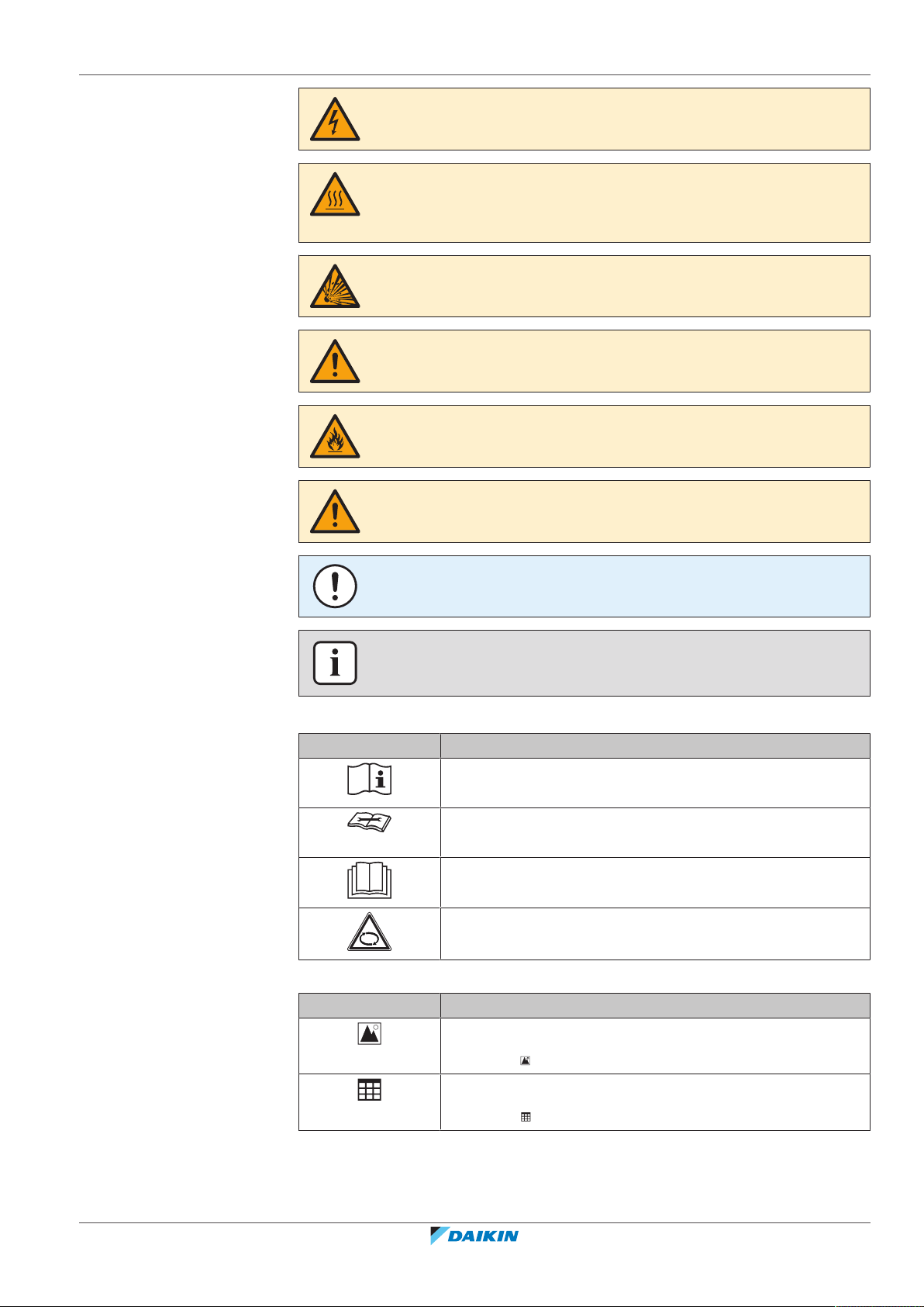
Symbols used on the unit:
Symbol Explanation
Before installation, read the installation and operation
manual, and the wiring instruction sheet.
Before performing maintenance and service tasks, read the
service manual.
For more information, see the installer and user reference
guide.
The unit contains rotating parts. Be careful when servicing or
inspecting the unit.
Symbols used in the documentation:
Symbol Explanation
RXYSQ4~6T8V/YB
VRV IV-S system air conditioner
4P482277-1B – 2020.10
Indicates a figure title or a reference to it.
Example: " 1–3 Figure title" means "Figure 3 in chapter 1".
Indicates a table title or a reference to it.
Example: " 1–3 Table title" means "Table 3 in chapter 1".
Installer and user reference guide
7
2 | General safety precautions
2 General safety precautions
In this chapter
2.1 For the installer....................................................................................................................................................................... 8
2.1 For the installer
2.1.1 General
If you are NOT sure how to install or operate the unit, contact your dealer.
2.1.1 General ................................................................................................................................................................... 8
2.1.2 Installation site ....................................................................................................................................................... 9
2.1.3 Refrigerant — in case of R410A or R32 ................................................................................................................. 9
2.1.4 Electrical ................................................................................................................................................................. 11
DANGER: RISK OF BURNING/SCALDING
▪ Do NOT touch the refrigerant piping, water piping or internal parts during and
immediately after operation. It could be too hot or too cold. Give it time to return
to normal temperature. If you must touch it, wear protective gloves.
▪ Do NOT touch any accidental leaking refrigerant.
WARNING
Improper installation or attachment of equipment or accessories could result in
electrical shock, short-circuit, leaks, fire or other damage to the equipment. Only use
accessories, optional equipment and spare parts made or approved by Daikin.
WARNING
Make sure installation, testing and applied materials comply with applicable
legislation (on top of the instructions described in the Daikin documentation).
CAUTION
Wear adequate personal protective equipment (protective gloves, safety glasses,…)
when installing, maintaining or servicing the system.
WARNING
Tear apart and throw away plastic packaging bags so that nobody, especially
children, can play with them. Possible risk: suffocation.
WARNING
Provide adequate measures to prevent that the unit can be used as a shelter by small
animals. Small animals that make contact with electrical parts can cause
malfunctions, smoke or fire.
Installer and user reference guide
8
CAUTION
Do NOT touch the air inlet or aluminium fins of the unit.
RXYSQ4~6T8V/YB
VRV IV-S system air conditioner
4P482277-1B – 2020.10
2 | General safety precautions
CAUTION
▪ Do NOT place any objects or equipment on top of the unit.
▪ Do NOT sit, climb or stand on the unit.
NOTICE
Works executed on the outdoor unit are best done under dry weather conditions to
avoid water ingress.
In accordance with the applicable legislation, it might be necessary to provide a
logbook with the product containing at least: information on maintenance, repair
work, results of tests, stand-by periods,…
Also, at least, following information MUST be provided at an accessible place at the
product:
▪ Instructions for shutting down the system in case of an emergency
▪ Name and address of fire department, police and hospital
▪ Name, address and day and night telephone numbers for obtaining service
In Europe, EN378 provides the necessary guidance for this logbook.
2.1.2 Installation site
▪ Provide sufficient space around the unit for servicing and air circulation.
▪ Make sure the installation site withstands the weight and vibration of the unit.
▪ Make sure the area is well ventilated. Do NOT block any ventilation openings.
▪ Make sure the unit is level.
Do NOT install the unit in the following places:
▪ In potentially explosive atmospheres.
▪ In places where there is machinery that emits electromagnetic waves.
Electromagnetic waves may disturb the control system, and cause malfunction of
the equipment.
▪ In places where there is a risk of fire due to the leakage of flammable gases
(example: thinner or gasoline), carbon fibre, ignitable dust.
▪ In places where corrosive gas (example: sulphurous acid gas) is produced.
Corrosion of copper pipes or soldered parts may cause the refrigerant to leak.
2.1.3 Refrigerant — in case of R410A or R32
If applicable. See the installation manual or installer reference guide of your
application for more information.
RXYSQ4~6T8V/YB
VRV IV-S system air conditioner
4P482277-1B – 2020.10
NOTICE
Make sure refrigerant piping installation complies with applicable legislation. In
Europe, EN378 is the applicable standard.
NOTICE
Make sure the field piping and connections are NOT subjected to stress.
Installer and user reference guide
9
2 | General safety precautions
WARNING
During tests, NEVER pressurize the product with a pressure higher than the
maximum allowable pressure (as indicated on the nameplate of the unit).
WARNING
Take sufficient precautions in case of refrigerant leakage. If refrigerant gas leaks,
ventilate the area immediately. Possible risks:
▪ Excessive refrigerant concentrations in a closed room can lead to oxygen
deficiency.
▪ Toxic gas might be produced if refrigerant gas comes into contact with fire.
DANGER: RISK OF EXPLOSION
Pump down – Refrigerant leakage. If you want to pump down the system, and there
is a leak in the refrigerant circuit:
▪ Do NOT use the unit's automatic pump down function, with which you can collect
all refrigerant from the system into the outdoor unit. Possible consequence: Selfcombustion and explosion of the compressor because of air going into the
operating compressor.
▪ Use a separate recovery system so that the unit's compressor does NOT have to
operate.
WARNING
ALWAYS recover the refrigerant. Do NOT release them directly into the environment.
Use a vacuum pump to evacuate the installation.
NOTICE
After all the piping has been connected, make sure there is no gas leak. Use nitrogen
to perform a gas leak detection.
NOTICE
▪ To avoid compressor breakdown, do NOT charge more than the specified amount
of refrigerant.
▪ When the refrigerant system is to be opened, refrigerant MUST be treated
according to the applicable legislation.
WARNING
Make sure there is no oxygen in the system. Refrigerant may only be charged after
performing the leak test and the vacuum drying.
Possible consequence: Self-combustion and explosion of the compressor because of
oxygen going into the operating compressor.
▪ In case recharge is required, see the nameplate of the unit. It states the type of
refrigerant and necessary amount.
Installer and user reference guide
10
▪ The unit is factory charged with refrigerant and depending on pipe sizes and pipe
lengths some systems require additional charging of refrigerant.
▪ Only use tools exclusively for the refrigerant type used in the system, this to
ensure pressure resistance and prevent foreign materials from entering into the
system.
▪ Charge the liquid refrigerant as follows:
RXYSQ4~6T8V/YB
VRV IV-S system air conditioner
4P482277-1B – 2020.10
2 | General safety precautions
If Then
A siphon tube is present
Charge with the cylinder upright.
(i.e., the cylinder is marked with "Liquid
filling siphon attached")
A siphon tube is NOT present Charge with the cylinder upside down.
▪ Open refrigerant cylinders slowly.
▪ Charge the refrigerant in liquid form. Adding it in gas form may prevent normal
operation.
CAUTION
When the refrigerant charging procedure is done or when pausing, close the valve of
the refrigerant tank immediately. If the valve is NOT closed immediately, remaining
pressure might charge additional refrigerant. Possible consequence: Incorrect
refrigerant amount.
2.1.4 Electrical
DANGER: RISK OF ELECTROCUTION
▪ Turn OFF all power supply before removing the switch box cover, connecting
electrical wiring or touching electrical parts.
▪ Disconnect the power supply for more than 10minutes, and measure the voltage
at the terminals of main circuit capacitors or electrical components before
servicing. The voltage MUST be less than 50VDC before you can touch electrical
components. For the location of the terminals, see the wiring diagram.
▪ Do NOT touch electrical components with wet hands.
▪ Do NOT leave the unit unattended when the service cover is removed.
WARNING
If NOT factory installed, a main switch or other means for disconnection, having a
contact separation in all poles providing full disconnection under overvoltage
categoryIII condition, MUST be installed in the fixed wiring.
RXYSQ4~6T8V/YB
VRV IV-S system air conditioner
4P482277-1B – 2020.10
Installer and user reference guide
11
2 | General safety precautions
WARNING
▪ ONLY use copper wires.
▪ Make sure the field wiring complies with the applicable legislation.
▪ All field wiring MUST be performed in accordance with the wiring diagram
supplied with the product.
▪ NEVER squeeze bundled cables and make sure they do NOT come in contact with
the piping and sharp edges. Make sure no external pressure is applied to the
terminal connections.
▪ Make sure to install earth wiring. Do NOT earth the unit to a utility pipe, surge
absorber, or telephone earth. Incomplete earth may cause electrical shock.
▪ Make sure to use a dedicated power circuit. NEVER use a power supply shared by
another appliance.
▪ Make sure to install the required fuses or circuit breakers.
▪ Make sure to install an earth leakage protector. Failure to do so may cause
electrical shock or fire.
▪ When installing the earth leakage protector, make sure it is compatible with the
inverter (resistant to high frequency electric noise) to avoid unnecessary opening
of the earth leakage protector.
CAUTION
▪ When connecting the power supply: connect the earth cable first, before making
the current-carrying connections.
▪ When disconnecting the power supply: disconnect the current-carrying cables
first, before separating the earth connection.
▪ The length of the conductors between the power supply stress relief and the
terminal block itself must be as such that the current-carrying wires are tautened
before the earth wire is in case the power supply is pulled loose from the stress
relief.
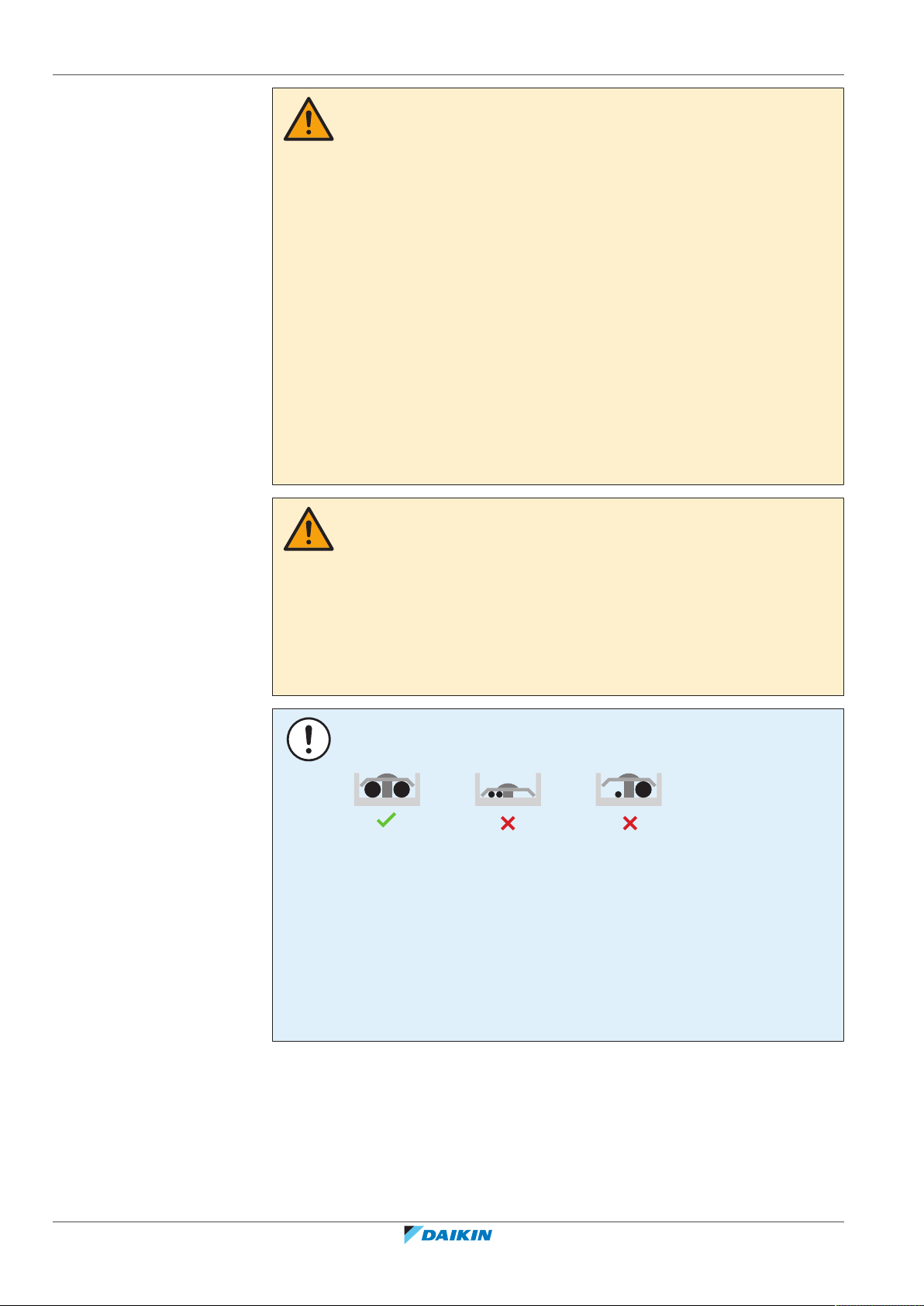
NOTICE
Precautions when laying power wiring:
▪ Do NOT connect wiring of different thicknesses to the power terminal block (slack
in the power wiring may cause abnormal heat).
▪ When connecting wiring which is the same thickness, do as shown in the figure
above.
▪ For wiring, use the designated power wire and connect firmly, then secure to
prevent outside pressure being exerted on the terminal board.
▪ Use an appropriate screwdriver for tightening the terminal screws. A screwdriver
with a small head will damage the head and make proper tightening impossible.
▪ Over-tightening the terminal screws may break them.
Installer and user reference guide
12
Install power cables at least 1 m away from televisions or radios to prevent
interference. Depending on the radio waves, a distance of 1 m may not be
sufficient.
RXYSQ4~6T8V/YB
VRV IV-S system air conditioner
4P482277-1B – 2020.10
2 | General safety precautions
WARNING
▪ After finishing the electrical work, confirm that each electrical component and
terminal inside the electrical components box is connected securely.
▪ Make sure all covers are closed before starting up the unit.
NOTICE
Only applicable if the power supply is three‑phase, and the compressor has an ON/
OFF starting method.
If there exists the possibility of reversed phase after a momentary black out and the
power goes on and off while the product is operating, attach a reversed phase
protection circuit locally. Running the product in reversed phase can break the
compressor and other parts.
RXYSQ4~6T8V/YB
VRV IV-S system air conditioner
4P482277-1B – 2020.10
Installer and user reference guide
13
3 | Specific installer safety instructions
3 Specific installer safety instructions
Always observe the following safety instructions and regulations.
WARNING
Tear apart and throw away plastic packaging bags so that nobody, especially
children, can play with them. Possible risk: suffocation.
CAUTION
Appliance not accessible to the general public, install it in a secured area, protected
from easy access.
This unit, both indoor and outdoor, is suitable for installation in a commercial and
light industrial environment.
CAUTION
Excessive refrigerant concentrations in a closed room can lead to oxygen deficiency.
DANGER: RISK OF ELECTROCUTION
Do NOT leave the unit unattended when the service cover is removed.
DANGER: RISK OF BURNING/SCALDING
DANGER: RISK OF ELECTROCUTION
WARNING
Take sufficient precautions in case of refrigerant leakage. If refrigerant gas leaks,
ventilate the area immediately. Possible risks:
▪ Excessive refrigerant concentrations in a closed room can lead to oxygen
deficiency.
▪ Toxic gas might be produced if refrigerant gas comes into contact with fire.
WARNING
ALWAYS recover the refrigerant. Do NOT release them directly into the environment.
Use a vacuum pump to evacuate the installation.
WARNING
During tests, NEVER pressurize the product with a pressure higher than the
maximum allowable pressure (as indicated on the nameplate of the unit).
Installer and user reference guide
14
CAUTION
Do not vent gases into the atmosphere.
WARNING
Any gas or oil remaining inside the stop valve may blow off the spun piping.
If these instructions are NOT followed correctly it may result in property damage or
personal injury, which may be serious depending on the circumstances.
RXYSQ4~6T8V/YB
VRV IV-S system air conditioner
4P482277-1B – 2020.10
3 | Specific installer safety instructions
WARNING
NEVER remove the spun piping by brazing.
Any gas or oil remaining inside the stop valve may blow off the spun piping.
WARNING
▪ ONLY use R410A as refrigerant. Other substances may cause explosions and
accidents.
▪ R410A contains fluorinated greenhouse gases. Its global warming potential (GWP)
value is 2087.5. Do NOT vent these gases into the atmosphere.
▪ When charging refrigerant, ALWAYS use protective gloves and safety glasses.
CAUTION
Do NOT push or place redundant cable length in the unit.
WARNING
▪ If the power supply has a missing or wrong N-phase, equipment might break
down.
▪ Establish proper earthing. Do NOT earth the unit to a utility pipe, surge absorber,
or telephone earth. Incomplete earthing may cause electrical shock.
▪ Install the required fuses or circuit breakers.
▪ Secure the electrical wiring with cable ties so that the cables do NOT come in
contact with sharp edges or piping, particularly on the high-pressure side.
▪ Do NOT use taped wires, stranded conductor wires, extension cords, or
connections from a star system. They can cause overheating, electrical shock or
fire.
▪ Do NOT install a phase advancing capacitor, because this unit is equipped with an
inverter. A phase advancing capacitor will reduce performance and may cause
accidents.
WARNING
▪ All wiring MUST be performed by an authorised electrician and MUST comply
with the applicable legislation.
▪ Make electrical connections to the fixed wiring.
▪ All components procured on-site and all electrical construction MUST comply
with the applicable legislation.
RXYSQ4~6T8V/YB
VRV IV-S system air conditioner
4P482277-1B – 2020.10
WARNING
ALWAYS use multicore cable for power supply cables.
Installer and user reference guide
15
3 | Specific installer safety instructions
CAUTION
▪ When connecting the power supply: connect the earth cable first, before making
the current-carrying connections.
▪ When disconnecting the power supply: disconnect the current-carrying cables
first, before separating the earth connection.
▪ The length of the conductors between the power supply stress relief and the
terminal block itself must be as such that the current-carrying wires are tautened
before the earth wire is in case the power supply is pulled loose from the stress
relief.
CAUTION
Do NOT perform the test operation while working on the indoor units.
When performing the test operation, NOT only the outdoor unit, but the connected
indoor unit will operate as well. Working on an indoor unit while performing a test
operation is dangerous.
CAUTION
Do NOT insert fingers, rods or other objects into the air inlet or outlet. Do NOT
remove the fan guard. When the fan is rotating at high speed, it will cause injury.
Installer and user reference guide
16
VRV IV-S system air conditioner
RXYSQ4~6T8V/YB
4P482277-1B – 2020.10

For the user
For the user
RXYSQ4~6T8V/YB
VRV IV-S system air conditioner
4P482277-1B – 2020.10
Installer and user reference guide
17
4 | User safety instructions
4 User safety instructions
Always observe the following safety instructions and regulations.
In this chapter
4.1 General.................................................................................................................................................................................... 18
4.2 Instructions for safe operation............................................................................................................................................... 19
4.1 General
WARNING
If you are NOT sure how to operate the unit, contact your
installer.
WARNING
Children aged from 8 years and above and persons with
reduced physical, sensory or mental capabilities or lack of
experience and knowledge can only use this appliance if
they have been given supervision or instruction concerning
the use of the appliance by a person responsible for their
safety.
Children MUST NOT play with the appliance.
Cleaning and user maintenance MUST NOT be carried out
by children without supervision.
WARNING
To prevent electrical shocks or fire:
▪ Do NOT rinse the unit.
▪ Do NOT operate the unit with wet hands.
▪ Do NOT place any objects containing water on the unit.
CAUTION
▪ Do NOT place any objects or equipment on top of the
unit.
▪ Do NOT sit, climb or stand on the unit.
Installer and user reference guide
18
VRV IV-S system air conditioner
RXYSQ4~6T8V/YB
4P482277-1B – 2020.10
4 | User safety instructions
▪ Units are marked with the following symbol:
This means that electrical and electronic products may NOT be mixed with
unsorted household waste. Do NOT try to dismantle the system yourself: the
dismantling of the system, treatment of the refrigerant, of oil and of other parts
must be done by an authorized installer and must comply with applicable
legislation.
Units must be treated at a specialized treatment facility for reuse, recycling and
recovery. By ensuring this product is disposed of correctly, you will help to
prevent potential negative consequences for the environment and human
health. For more information, contact your installer or local authority.
▪ Batteries are marked with the following symbol:
This means that the batteries may NOT be mixed with unsorted household
waste. If a chemical symbol is printed beneath the symbol, this chemical symbol
means that the battery contains a heavy metal above a certain concentration.
Possible chemical symbols are: Pb: lead (>0.004%).
Waste batteries must be treated at a specialized treatment facility for reuse. By
ensuring waste batteries are disposed of correctly, you will help to prevent
potential negative consequences for the environment and human health.
4.2 Instructions for safe operation
CAUTION
▪ NEVER touch the internal parts of the controller.
▪ Do NOT remove the front panel. Some parts inside are
dangerous to touch and appliance problems may
happen. For checking and adjusting the internal parts,
contact your dealer.
CAUTION
Do NOT operate the system when using a room
fumigation-type insecticide. Chemicals could collect in the
unit, and endanger the health of people who are
hypersensitive to chemicals.
RXYSQ4~6T8V/YB
VRV IV-S system air conditioner
4P482277-1B – 2020.10
CAUTION
It is unhealthy to expose your body to the air flow for a
long time.
Installer and user reference guide
19
4 | User safety instructions
CAUTION
To avoid oxygen deficiency, ventilate the room sufficiently
if equipment with burner is used together with the system.
WARNING
This unit contains electrical and hot parts.
WARNING
Before operating the unit, be sure the installation has been
carried out correctly by an installer.
WARNING
Never touch the air outlet or the horizontal blades while
the swing flap is in operation. Fingers may become caught
or the unit may break down.
CAUTION
Do NOT insert fingers, rods or other objects into the air
inlet or outlet. Do NOT remove the fan guard. When the
fan is rotating at high speed, it will cause injury.
CAUTION: Pay attention to the fan!
It is dangerous to inspect the unit while the fan is running.
Be sure to turn off the main switch before executing any
maintenance task.
CAUTION
After a long use, check the unit stand and fitting for
damage. If damaged, the unit may fall and result in injury.
WARNING
NEVER replace a fuse with a fuse of a wrong ampere
ratings or other wires when a fuse blows out. Use of wire
or copper wire may cause the unit to break down or cause
a fire.
Installer and user reference guide
20
VRV IV-S system air conditioner
RXYSQ4~6T8V/YB
4P482277-1B – 2020.10
4 | User safety instructions
WARNING
▪ Do NOT modify, disassemble, remove, reinstall or repair
the unit yourself as incorrect dismantling or installation
may cause an electric shock or fire. Contact your dealer.
▪ In case of accidental refrigerant leaks, make sure there
are no naked flames. The refrigerant itself is entirely
safe, non-toxic and non-combustible, but it will generate
toxic gas when it accidentally leaks into a room where
combustible air from fan heaters, gas cookers, etc. is
present. Always have qualified service personnel
confirm that the point of leakage has been repaired or
corrected before resuming operation.
WARNING
Stop operation and shut off the power if anything
unusual occurs (burning smells etc.).
Leaving the unit running under such circumstances may
cause breakage, electric shock or fire. Contact your dealer.
WARNING
The refrigerant in the system is safe and normally does not
leak. If the refrigerant leaks in the room, contact with a fire
of a burner, a heater or a cooker may result in a harmful
gas.
Turn off any combustible heating devices, ventilate the
room and contact the dealer where you purchased the
unit.
Do not use the system until a service person confirms that
the portion where the refrigerant leaks is repaired.
CAUTION
NEVER expose little children, plants or animals directly to
the airflow.
RXYSQ4~6T8V/YB
VRV IV-S system air conditioner
4P482277-1B – 2020.10
Installer and user reference guide
21
5 | About the system
g
d d
c c
f
e
b
a
g
f
e
5 About the system
The indoor unit part of this VRV heat pump system can be used for heating/cooling
applications. The type of indoor unit which can be used depends on the outdoor
units series.
NOTICE
Do NOT use the system for other purposes. In order to avoid any quality
deterioration, do NOT use the unit for cooling precision instruments, food, plants,
animals, or works of art.
NOTICE
For future modifications or expansions of your system:
A full overview of allowable combinations (for future system extensions) is available
in technical engineering data and should be consulted. Contact your installer to
receive more information and professional advice.
INFORMATION
▪ Combination of VRVDX and RADX indoor units is not allowed.
▪ Combination of RADX and AHU indoor units is not allowed.
▪ Combination of RADX and aircurtain indoor units is not allowed.
In general following type of indoor units can be connected to a VRV heat pump
system (not exhaustive list, depending on outdoor unit model and indoor unit
model combinations):
▪ VRV direct expansion indoor units (air to air applications).
▪ RA direct expansion indoor units (air to air applications).
▪ AHU (air to air applications): EKEXV-kit is required.
▪ Aircurtain -Biddle- (air to air applications).
Airhandling unit connection in pair to VRV heat pump outdoor unit is supported.
Airhandling unit connection in multi to VRV heat pump outdoor unit is supported,
even combined with VRV direct expansion indoor unit(s).
For more specifications, see technical engineering data.
In this chapter
5.1 System layout.......................................................................................................................................................................... 22
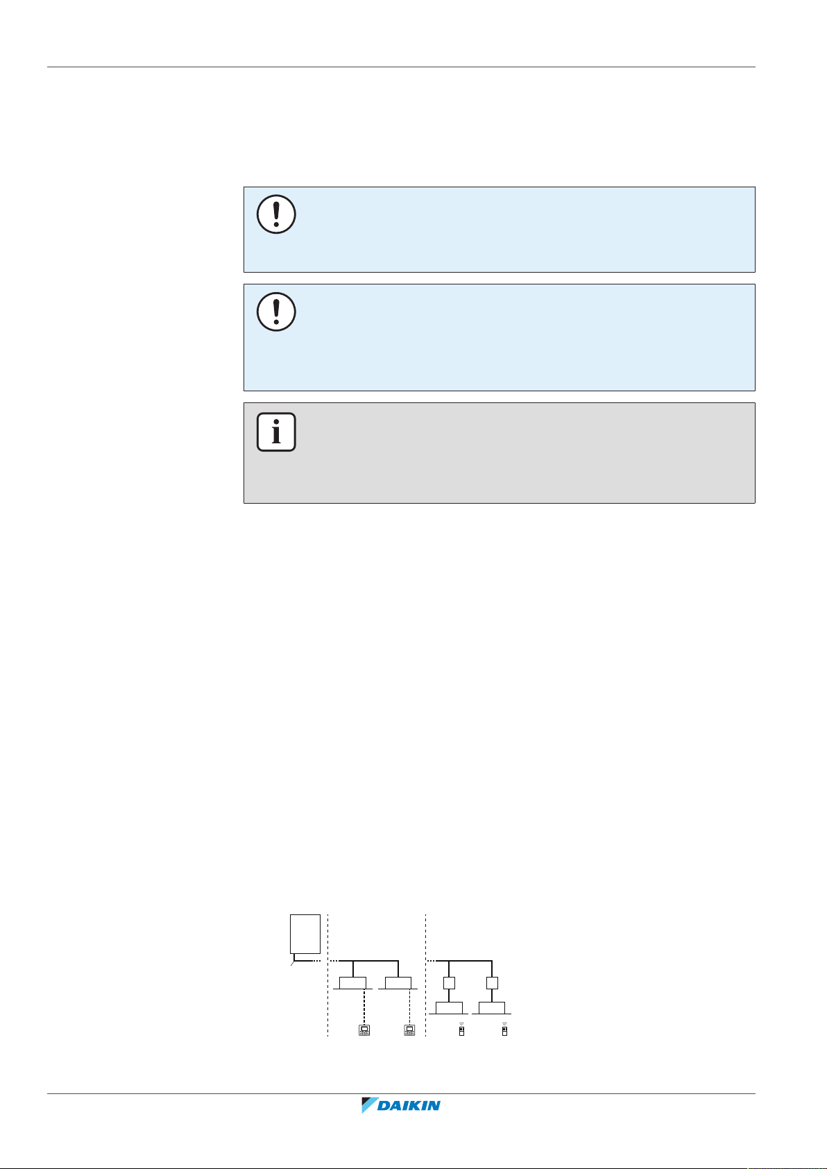
5.1 System layout
Installer and user reference guide
22
a VRV IV-S Heat pump outdoor unit
b Refrigerant piping
c VRV direct expansion (DX) indoor unit
RXYSQ4~6T8V/YB
VRV IV-S system air conditioner
4P482277-1B – 2020.10

5 | About the system
d User interface (dedicated depending on indoor unit type)
e BP box (required to connect Residential Air (RA) or Sky Air (SA) direct expansion
(DX) indoor units)
f Residential Air (RA) direct expansion (DX) indoor units
g User interface (wireless, dedicated depending on indoor unit type)
RXYSQ4~6T8V/YB
VRV IV-S system air conditioner
4P482277-1B – 2020.10
Installer and user reference guide
23

6 | User interface
6 User interface
CAUTION
▪ NEVER touch the internal parts of the controller.
▪ Do NOT remove the front panel. Some parts inside are dangerous to touch and
appliance problems may happen. For checking and adjusting the internal parts,
contact your dealer.
This operation manual offers a non-exhaustive overview of the main functions of
the system.
Detailed information on required actions to achieve certain functions can be found
in the dedicated installation and operation manual of the indoor unit.
Refer to the operation manual of the installed user interface.
Installer and user reference guide
24
VRV IV-S system air conditioner
RXYSQ4~6T8V/YB
4P482277-1B – 2020.10
7 Before operation
WARNING
This unit contains electrical and hot parts.
WARNING
Before operating the unit, be sure the installation has been carried out correctly by
an installer.
NOTICE
NEVER inspect or service the unit by yourself. Ask a qualified service person to
perform this work.
CAUTION
It is unhealthy to expose your body to the air flow for a long time.
CAUTION
To avoid oxygen deficiency, ventilate the room sufficiently if equipment with burner
is used together with the system.
7 | Before operation
CAUTION
Do NOT operate the system when using a room fumigation-type insecticide.
Chemicals could collect in the unit, and endanger the health of people who are
hypersensitive to chemicals.
NOTICE
Be sure to turn ON the power 6 hours before operation in order to have power
running to the crankcase heater and to protect the compressor.
This operation manual is for the following systems with standard control. Before
initiating operation, contact your dealer for the operation that corresponds to your
system type and mark. If your installation has a customised control system, ask
your dealer for the operation that corresponds to your system.
Operation modes (depending on indoor unit type):
▪ Heating and cooling (air to air).
▪ Fan only operation (air to air).
Dedicated functions exist depending on the type of indoor unit, refer to dedicated
installation/operation manual for more information.
RXYSQ4~6T8V/YB
VRV IV-S system air conditioner
4P482277-1B – 2020.10
Installer and user reference guide
25
8 | Operation
8 Operation
8.1 Operation range
In this chapter
8.1 Operation range...................................................................................................................................................................... 26
8.2 Operating the system ............................................................................................................................................................. 26
8.2.1 About operating the system .................................................................................................................................. 26
8.2.2 About cooling, heating, fan only, and automatic operation ................................................................................. 27
8.2.3 About the heating operation ................................................................................................................................. 27
8.2.4 To operate the system (WITHOUT cool/heat changeover remote control switch) ............................................. 27
8.2.5 To operate the system (WITH cool/heat changeover remote control switch)..................................................... 28
8.3 Using the dry program............................................................................................................................................................ 29
8.3.1 About the dry program .......................................................................................................................................... 29
8.3.2 To use the dry program (WITHOUT cool/heat changeover remote control switch)............................................ 29
8.3.3 To use the dry program (WITH cool/heat changeover remote control switch) ................................................... 29
8.4 Adjusting the air flow direction.............................................................................................................................................. 30
8.4.1 About the air flow flap ........................................................................................................................................... 30
8.5 Setting the master user interface .......................................................................................................................................... 31
8.5.1 About setting the master user interface ............................................................................................................... 31
8.5.2 To designate the master user interface................................................................................................................. 31
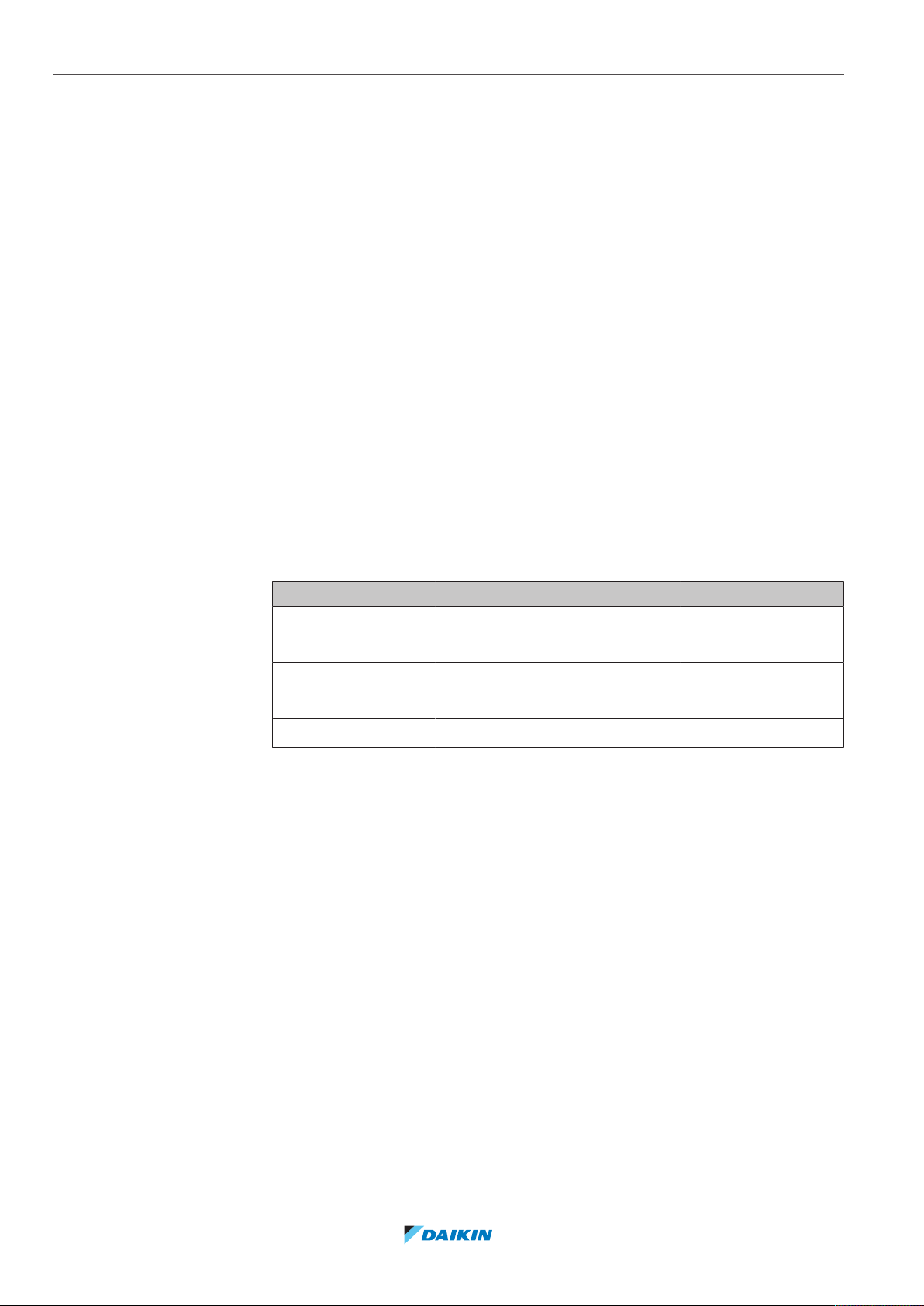
Use the system in the following temperature and humidity ranges for safe and
effective operation.
Outdoor temperature –5~46°CDB –20~21°CDB
Indoor temperature 21~32°CDB
Indoor humidity ≤80%
(a)
To avoid condensation and water dripping out of the unit. If the temperature or the
humidity is beyond these conditions, safety devices may be put in action and the air
conditioner may not operate.
Above operation range is only valid in case direct expansion indoor units are
connected to the VRV system.
Special operation ranges are valid in case of using AHU. They can be found in the
installation/operation manual of the dedicated unit. Latest information can be
found in the technical engineering data.
8.2 Operating the system
Cooling Heating
–20~15.5°CWB
15~27°CDB
14~25°CWB
(a)
8.2.1 About operating the system
Installer and user reference guide
26
▪ Operation procedure varies according to the combination of outdoor unit and
user interface.
▪ To protect the unit, turn on the main power switch 6 hours before operation.
RXYSQ4~6T8V/YB
VRV IV-S system air conditioner
4P482277-1B – 2020.10
8.2.2 About cooling, heating, fan only, and automatic operation
▪ Changeover cannot be made with a user interface whose display shows
"change-over under centralised control" (refer to installation and operation
manual of the user interface).
▪ When the display "change-over under centralised control" flashes, refer to
"About setting the master user interface"[431].
▪ The fan may keep on running for about 1 minute after the heating operation
stops.
▪ The air flow rate may adjust itself depending on the room temperature or the fan
may stop immediately. This is not a malfunction.
8.2.3 About the heating operation
It may take longer to reach the set temperature for general heating operation than
for cooling operation.
The following operation is performed in order to prevent the heating capacity from
dropping or cold air from blowing.
Defrost operation
8 | Operation
In heating operation, freezing of the outdoor unit's air cooled coil increases over
time, restricting the energy transfer to the outdoor unit's coil. Heating capability
decreases and the system needs to go into defrost operation to be able to remove
frost from the outdoor unit’s coil. During defrost operation the heating capacity on
the indoor unit side will temporarily drop until defrosting is completed. After
defrosting, the unit will regain its full heating capacity.
The indoor unit will stop fan operation, the refrigerant cycle will reverse and
energy from inside the building will be used to defrost the outdoor unit coil.
The indoor unit will indicate defrost operation on the display .
Hot start
In order to prevent cold air from blowing out of an indoor unit at the start of
heating operation, the indoor fan is automatically stopped. The display of the user
interface shows . It may take some time before the fan starts. This is not a
malfunction.
INFORMATION
▪ The heating capacity drops when the outside temperature falls. If this happens,
use another heating device together with the unit. (When using together with
appliances that produce open fire, ventilate the room constantly). Do not place
appliances that produce open fire in places exposed to the air flow from the unit
or under the unit.
▪ It takes some time to heat up the room from the time the unit is started since the
unit uses a hot-air circulating system to heat the entire room.
▪ If the hot air rises to the ceiling, leaving the area above the floor cold, we
recommend that you use the circulator (the indoor fan for circulating air).
Contact your dealer for details.
8.2.4 To operate the system (WITHOUT cool/heat changeover remote control switch)
RXYSQ4~6T8V/YB
VRV IV-S system air conditioner
4P482277-1B – 2020.10
1 Press the operation mode selector button on the user interface several times
and select the operation mode of your choice.
Installer and user reference guide
27

8 | Operation
a
b
1
1
1
1
1
8.2.5 To operate the system (WITH cool/heat changeover remote control switch)
Cooling operation
Heating operation
Fan only operation
2 Press the ON/OFF button on the user interface.
Result: The operation lamp lights up and the system starts operating.
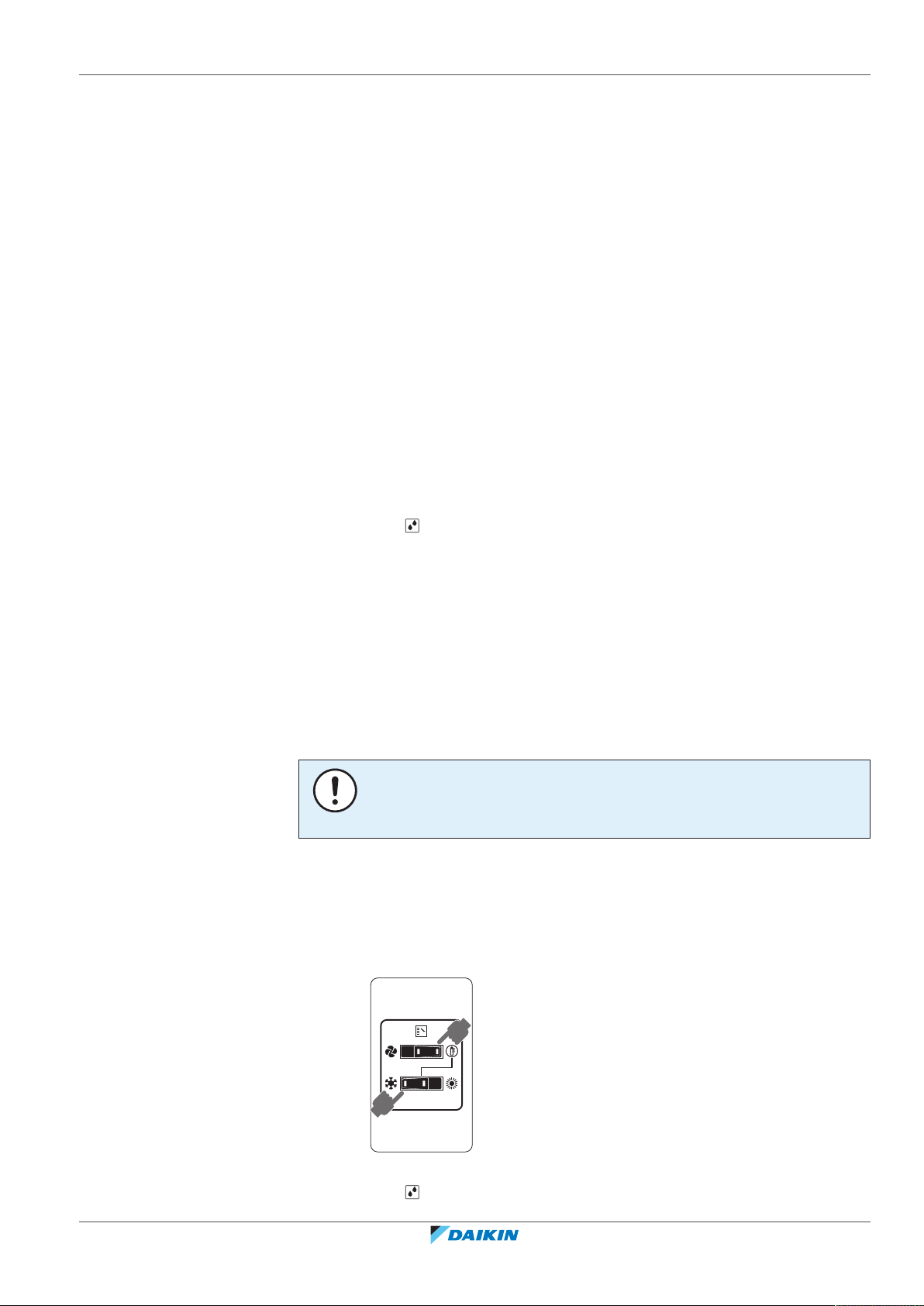
Overview of the changeover remote control switch
a FAN ONLY/AIR CONDITIONING SELECTOR
SWITCH
Set the switch to for fan only operation or to
for heating or cooling operation.
b COOL/HEAT CHANGEOVER SWITCH
Set the switch to for cooling or to for
heating
Note: In case a cool/heat changeover remote control switch is used, the position of
DIP switch 1 (DS1-1) on the main PCB needs to be switched to the ON position.
To start
1 Select operation mode with the cool/heat changeover switch as follows:
Cooling operation
Heating operation
Fan only operation
2 Press the ON/OFF button on the user interface.
Result: The operation lamp lights up and the system starts operating.
Installer and user reference guide
28
To stop
3 Press the ON/OFF button on the user interface once again.
Result: The operation lamp goes out and the system stops operating.
NOTICE
Do not turn off power immediately after the unit stops, but wait for at least 5
minutes.
RXYSQ4~6T8V/YB
VRV IV-S system air conditioner
4P482277-1B – 2020.10
8 | Operation
1
1
To adjust
For programming temperature, fan speed and air flow direction refer to the
operation manual of the user interface.
8.3 Using the dry program
8.3.1 About the dry program
▪ The function of this program is to decrease the humidity in your room with
minimal temperature decrease (minimal room cooling).
▪ The micro computer automatically determines temperature and fan speed
(cannot be set by the user interface).
▪ The system does not go into operation if the room temperature is low (<20°C).
8.3.2 To use the dry program (WITHOUT cool/heat changeover remote control switch)
To start
1 Press the operation mode selector button on the user interface several times
and select (program dry operation).
2 Press the ON/OFF button of the user interface.
Result: The operation lamp lights up and the system starts operating.
3 Press the air flow direction adjust button (only for double-flow, multi-flow,
corner, ceiling-suspended and wall-mounted). Refer to "8.4 Adjusting the air
flow direction"[430] for details.
To stop
4 Press the ON/OFF button on the user interface once again.
Result: The operation lamp goes out and the system stops operating.
NOTICE
Do not turn off power immediately after the unit stops, but wait for at least 5
minutes.
8.3.3 To use the dry program (WITH cool/heat changeover remote control switch)
To start
1 Select cooling operation mode with the cool/heat changeover remote control
switch.
RXYSQ4~6T8V/YB
VRV IV-S system air conditioner
4P482277-1B – 2020.10
2 Press the operation mode selector button on the user interface several times
and select (program dry operation).
Installer and user reference guide
29
8 | Operation
8.4 Adjusting the air flow direction
3 Press the ON/OFF button of the user interface.
Result: The operation lamp lights up and the system starts operating.
4 Press the air flow direction adjust button (only for double-flow, multi-flow,
corner, ceiling-suspended and wall-mounted). Refer to "8.4 Adjusting the air
flow direction"[430] for details.
To stop
5 Press the ON/OFF button on the user interface once again.
Result: The operation lamp goes out and the system stops operating.
NOTICE
Do not turn off power immediately after the unit stops, but wait for at least 5
minutes.
Refer to the operation manual of the user interface.
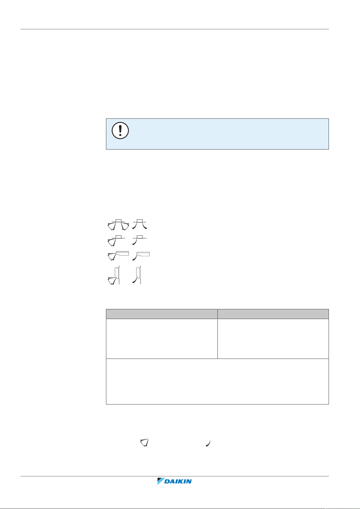
8.4.1 About the air flow flap
For the following conditions, a micro computer controls the air flow direction
which may be different from the display.
▪ When the room temperature is lower
than the set temperature.
▪ When operating continuously at horizontal air flow direction.
▪ When continuous operation with downward air flow is performed at the time of
cooling with a ceiling-suspended or a wall-mounted unit, the micro computer
may control the flow direction, and then the user interface indication will also
change.
Double flow+multi-flow units
Corner units
Ceiling suspended units
Wall-mounted units
Cooling Heating
▪ When starting operation.
▪ When the room temperature is higher
than the set temperature.
▪ At defrost operation.
Installer and user reference guide
30
The air flow direction can be adjusted in one of the following ways:
▪ The air flow flap itself adjusts its position.
▪ The air flow direction can be fixed by the user.
▪ Automatic and desired position .
RXYSQ4~6T8V/YB
VRV IV-S system air conditioner
4P482277-1B – 2020.10

WARNING
g
d d
c c
f
e
b
a
g
f
e
Never touch the air outlet or the horizontal blades while the swing flap is in
operation. Fingers may become caught or the unit may break down.
NOTICE
▪ The movable limit of the flap is changeable. Contact your dealer for details. (only
for double-flow, multi-flow, corner, ceiling-suspended and wall-mounted).
▪ Avoid operating in the horizontal direction . It may cause dew or dust to
settle on the ceiling or flap.
8.5 Setting the master user interface
8.5.1 About setting the master user interface
8 | Operation
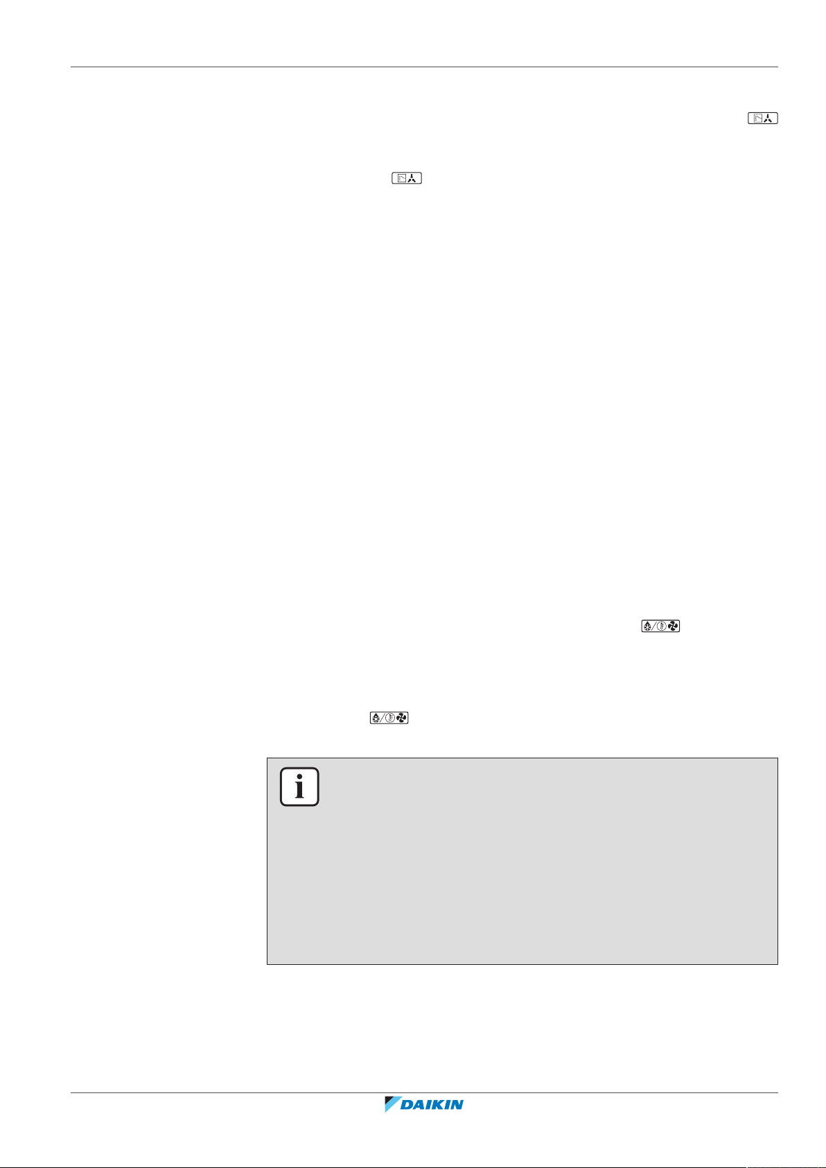
a VRV IV-S Heat pump outdoor unit
b Refrigerant piping
c VRV direct expansion (DX) indoor unit
d User interface (dedicated depending on indoor unit type)
e BP box (required to connect Residential Air (RA) or Sky Air (SA) direct expansion
(DX) indoor units)
f Residential Air (RA) direct expansion (DX) indoor units
g User interface (wireless, dedicated depending on indoor unit type)
When the system is installed as shown in the figure above, it is necessary to
designate one of the user interfaces as the master user interface.
The displays of slave user interfaces show (change-over under centralised
control) and slave user interfaces automatically follow the operation mode
directed by the master user interface.
Only the master user interface can select heating or cooling mode.
8.5.2 To designate the master user interface
RXYSQ4~6T8V/YB
VRV IV-S system air conditioner
4P482277-1B – 2020.10
Installer and user reference guide
31

9 | Energy saving and optimum operation
9 Energy saving and optimum operation
Observe the following precautions to ensure the system operates properly.
▪ Adjust the air outlet properly and avoid direct air flow to room inhabitants.
▪ Adjust the room temperature properly for a comfortable environment. Avoid
excessive heating or cooling.
▪ Prevent direct sunlight from entering a room during cooling operation by using
curtains or blinds.
▪ Ventilate often. Extended use requires special attention to ventilation.
▪ Keep doors and windows closed. If the doors and windows remain open, air will
flow out of your room causing a decrease in the cooling or heating effect.
▪ Be careful NOT to cool or heat too much. To save energy, keep the temperature
setting at a moderate level.
▪ NEVER place objects near the air inlet or the air outlet of the unit. Doing so may
cause a reduced heating/cooling effect or stop operation.
▪ Turn off the main power supply switch to the unit when the unit is not used for
longer periods of time. If the switch is on, it consumes electricity. Before
restarting the unit, turn on the main power supply switch 6 hours before
operation to ensure smooth running. (Refer to "Maintenance" in the indoor unit
manual.)
▪ When the display shows (time to clean the air filter), ask a qualified service
person to clean the filters. (Refer to "Maintenance" in the indoor unit manual.)
▪ Keep the indoor unit and user interface at least 1 m away from televisions,
radios, stereos, and other similar equipment. Failing to do so may cause static or
distorted pictures.
▪ Do NOT place items under the indoor unit, as they may be damaged by water.
▪ Condensation may form if the humidity is above 80% or if the drain outlet gets
blocked.
This heat pump system is equipped with advanced energy saving functionality.
Depending on the priority, emphasises can be put on energy saving or comfort
level. Several parameters can be selected, resulting in the optimal balance
between energy consumption and comfort for the particular application.
Several patterns are available and roughly explained below. Contact your installer
or dealer for advice or to modify the parameters to the needs of your building.
Detailed information is given for the installer in the installation manual. He can
help you to realize the best balance between energy consumption and comfort.
In this chapter
9.1 Available main operation methods ........................................................................................................................................ 32
9.2 Available comfort settings...................................................................................................................................................... 33
9.1 Available main operation methods
Installer and user reference guide
32
Basic
The refrigerant temperature is fixed independent from the situation. It
corresponds to the standard operation which is known and can be expected from/
under previous VRV systems.
RXYSQ4~6T8V/YB
VRV IV-S system air conditioner
4P482277-1B – 2020.10

9 | Energy saving and optimum operation
Automatic
The refrigerant temperature is set depending on the outdoor ambient conditions.
As such adjusting the refrigerant temperature to match the required load (which is
also related to the outdoor ambient conditions).
E.g., when your system is operating in cooling, you do not need as much cooling
under low outdoor ambient temperatures (e.g., 25°C) as under high outdoor
ambient temperatures (e.g., 35°C). Using this idea, the system automatically starts
increasing its refrigerant temperature, automatically reducing the delivered
capacity and increasing the system's efficiency.
Hi-sensible/economic (cooling/heating)
The refrigerant temperature is set higher/lower (cooling/heating) compared to
basic operation. The focus under high sensible mode is comfort feeling for the
customer.
The selection method of indoor units is important and has to be considered as the
available capacity is not the same as under basic operation.
For details concerning to Hi-sensible applications, please contact your installer.
9.2 Available comfort settings
For each of above modes a comfort level can be selected. The comfort level is
related to the timing and the effort (energy consumption) which is put in achieving
a certain room temperature by temporarily changing the refrigerant temperature
to different values in order to achieve requested conditions more quickly.
▪ Powerful
▪ Quick
▪ Mild
▪ Eco
RXYSQ4~6T8V/YB
VRV IV-S system air conditioner
4P482277-1B – 2020.10
Installer and user reference guide
33

10 | Maintenance and service
10 Maintenance and service
NOTICE
NEVER inspect or service the unit by yourself. Ask a qualified service person to
perform this work.
WARNING
NEVER replace a fuse with a fuse of a wrong ampere ratings or other wires when a
fuse blows out. Use of wire or copper wire may cause the unit to break down or
cause a fire.
CAUTION
Do NOT insert fingers, rods or other objects into the air inlet or outlet. Do NOT
remove the fan guard. When the fan is rotating at high speed, it will cause injury.
CAUTION: Pay attention to the fan!
It is dangerous to inspect the unit while the fan is running.
Be sure to turn off the main switch before executing any maintenance task.
CAUTION
After a long use, check the unit stand and fitting for damage. If damaged, the unit
may fall and result in injury.
NOTICE
Do NOT wipe the controller operation panel with benzine, thinner, chemical dust
cloth, etc. The panel may get discoloured or the coating peeled off. If it is heavily
dirty, soak a cloth in water-diluted neutral detergent, squeeze it well and wipe the
panel clean. Wipe it with another dry cloth.
In this chapter
10.1 Maintenance after a long stop period ................................................................................................................................... 34
10.2 Maintenance before a long stop period ................................................................................................................................ 35
10.3 About the refrigerant ............................................................................................................................................................. 35
10.4 After-sales service and warranty............................................................................................................................................ 35
10.4.1 Warranty period..................................................................................................................................................... 35
10.4.2 Recommended maintenance and inspection........................................................................................................ 36
10.4.3 Recommended maintenance and inspection cycles............................................................................................. 36
10.4.4 Shortened maintenance and replacement cycles................................................................................................. 37
10.1 Maintenance after a long stop period
Installer and user reference guide
34
E.g., at the beginning of the season.
▪ Check and remove everything that might be blocking inlet and outlet vents of
indoor units and outdoor units.
▪ Clean air filters and casings of indoor units. Contact your installer or maintenance
person to clean air filters and casings of the indoor unit. Maintenance tips and
procedures for cleaning are provided in the installation/operation manuals of
dedicated indoor units. Make sure to install cleaned air filters back in the same
position.
RXYSQ4~6T8V/YB
VRV IV-S system air conditioner
4P482277-1B – 2020.10
▪ Turn on the power at least 6 hours before operating the unit in order to ensure
smoother operation. As soon as the power is turned on, the user interface
display appears.
10.2 Maintenance before a long stop period
E.g., at the end of the season.
▪ Let the indoor units run in fan only operation for about half a day in order to dry
the interior of the units. Refer to "About cooling, heating, fan only, and
automatic operation"[427] for details on fan only operation.
▪ Turn off the power. The user interface display disappears.
▪ Clean air filters and casings of indoor units. Contact your installer or maintenance
person to clean air filters and casings of the indoor unit. Maintenance tips and
procedures for cleaning are provided in the installation/operation manuals of
dedicated indoor units. Make sure to install cleaned air filters back in the same
position.
10 | Maintenance and service
10.3 About the refrigerant
This product contains fluorinated greenhouse gases. Do NOT vent gases into the
atmosphere.
Refrigerant type: R410A
Global warming potential (GWP) value: 2087.5
NOTICE
Applicable legislation on fluorinated greenhouse gases requires that the refrigerant
charge of the unit is indicated both in weight and CO2 equivalent.
Formula to calculate the quantity in CO2 equivalent tonnes: GWP value of the
refrigerant × total refrigerant charge [in kg] / 1000
Please contact your installer for more information.
WARNING
The refrigerant in the system is safe and normally does not leak. If the refrigerant
leaks in the room, contact with a fire of a burner, a heater or a cooker may result in a
harmful gas.
Turn off any combustible heating devices, ventilate the room and contact the dealer
where you purchased the unit.
Do not use the system until a service person confirms that the portion where the
refrigerant leaks is repaired.
10.4 After-sales service and warranty
10.4.1 Warranty period
RXYSQ4~6T8V/YB
VRV IV-S system air conditioner
4P482277-1B – 2020.10
▪ This product includes a warranty card that was filled in by the dealer at the time
of installation. The completed card has to be checked by the customer and
stored carefully.
Installer and user reference guide
35
10 | Maintenance and service
▪ If repairs to the product are necessary within the warranty period, contact your
dealer and keep the warranty card at hand.
10.4.2 Recommended maintenance and inspection
Since dust collects when using the unit for several years, performance of the unit
will deteriorate to some extent. As taking apart and cleaning interiors of units
requires technical expertise and in order to ensure the best possible maintenance
of your units, we recommend to enter into a maintenance and inspection contract
on top of normal maintenance activities. Our network of dealers has access to a
permanent stock of essential components in order to keep your unit in operation
as long as possible. Contact your dealer for more information.
When asking your dealer for an intervention, always state:
▪ The complete model name of the unit.
▪ The manufacturing number (stated on the nameplate of the unit).
▪ The installation date.
▪ The symptoms or malfunction, and details of the defect.
WARNING
▪ Do NOT modify, disassemble, remove, reinstall or repair the unit yourself as
incorrect dismantling or installation may cause an electric shock or fire. Contact
your dealer.
▪ In case of accidental refrigerant leaks, make sure there are no naked flames. The
refrigerant itself is entirely safe, non-toxic and non-combustible, but it will
generate toxic gas when it accidentally leaks into a room where combustible air
from fan heaters, gas cookers, etc. is present. Always have qualified service
personnel confirm that the point of leakage has been repaired or corrected
before resuming operation.
10.4.3 Recommended maintenance and inspection cycles
Be aware that the mentioned maintenance and replacement cycles do not relate to
the warranty period of the components.
Component Inspection
Electric motor 1 year 20,000 hours
PCB 25,000 hours
Heat exchanger 5 years
Sensor (thermistor, etc.) 5 years
User interface and switches 25,000 hours
Drain pan 8 years
Expansion valve 20,000 hours
Solenoid valve 20,000 hours
The table assumes the following conditions of use:
▪ Normal use without frequent starting and stopping of the unit. Depending on the
model, we recommend not starting and stopping the machine more than 6
times/hour.
cycle
Maintenance cycle
(replacements and/or repairs)
Installer and user reference guide
36
▪ Operation of the unit is assumed to be 10hours/day and 2,500hours/year.
RXYSQ4~6T8V/YB
VRV IV-S system air conditioner
4P482277-1B – 2020.10
NOTICE
▪ The table indicates main components. Refer to your maintenance and inspection
contract for more details.
▪ The table indicates recommended intervals of maintenance cycles. However, in
order to keep the unit operational as long as possible, maintenance work may be
required sooner. Recommended intervals can be used for appropriate
maintenance design in terms of budgeting maintenance and inspection fees.
Depending on the content of the maintenance and inspection contract,
inspection and maintenance cycles may in reality be shorter than listed.
10.4.4 Shortened maintenance and replacement cycles
Shortening of "maintenance cycle" and "replacement cycle" needs to be
considered in following situations:
The unit is used in locations where:
▪ Heat and humidity fluctuate out of the ordinary.
▪ Power fluctuation is high (voltage, frequency, wave distortion, etc.) (the unit
cannot be used if power fluctuation is outside the allowable range).
▪ Bumps and vibrations are frequent.
10 | Maintenance and service
▪ Dust, salt, harmful gas or oil mist such as sulphurous acid and hydrogen sulfide
may be present in the air.
▪ The machine is started and stopped frequently or operation time is long (sites
with 24 hour air-conditioning).
Recommended replacement cycle of wear parts
Component Inspection
cycle
Maintenance cycle
(replacements and/or repairs)
Air filter 1 year 5 years
High efficiency filter 1 year
Fuse 10 years
Crankcase heater 8 years
Pressure containing parts In case of corrosion, contact
your local dealer.
NOTICE
▪ The table indicates main components. Refer to your maintenance and inspection
contract for more details.
▪ The table indicates recommended intervals of replacement cycles. However, in
order to keep the unit operational as long as possible, maintenance work may be
required sooner. Recommended intervals can be used for appropriate
maintenance design in terms of budgeting maintenance and inspection fees.
Contact your dealer for details.
RXYSQ4~6T8V/YB
VRV IV-S system air conditioner
4P482277-1B – 2020.10
INFORMATION
Damage due to taking apart or cleaning interiors of units by anyone other than our
authorised dealers may not be included in the warranty.
Installer and user reference guide
37
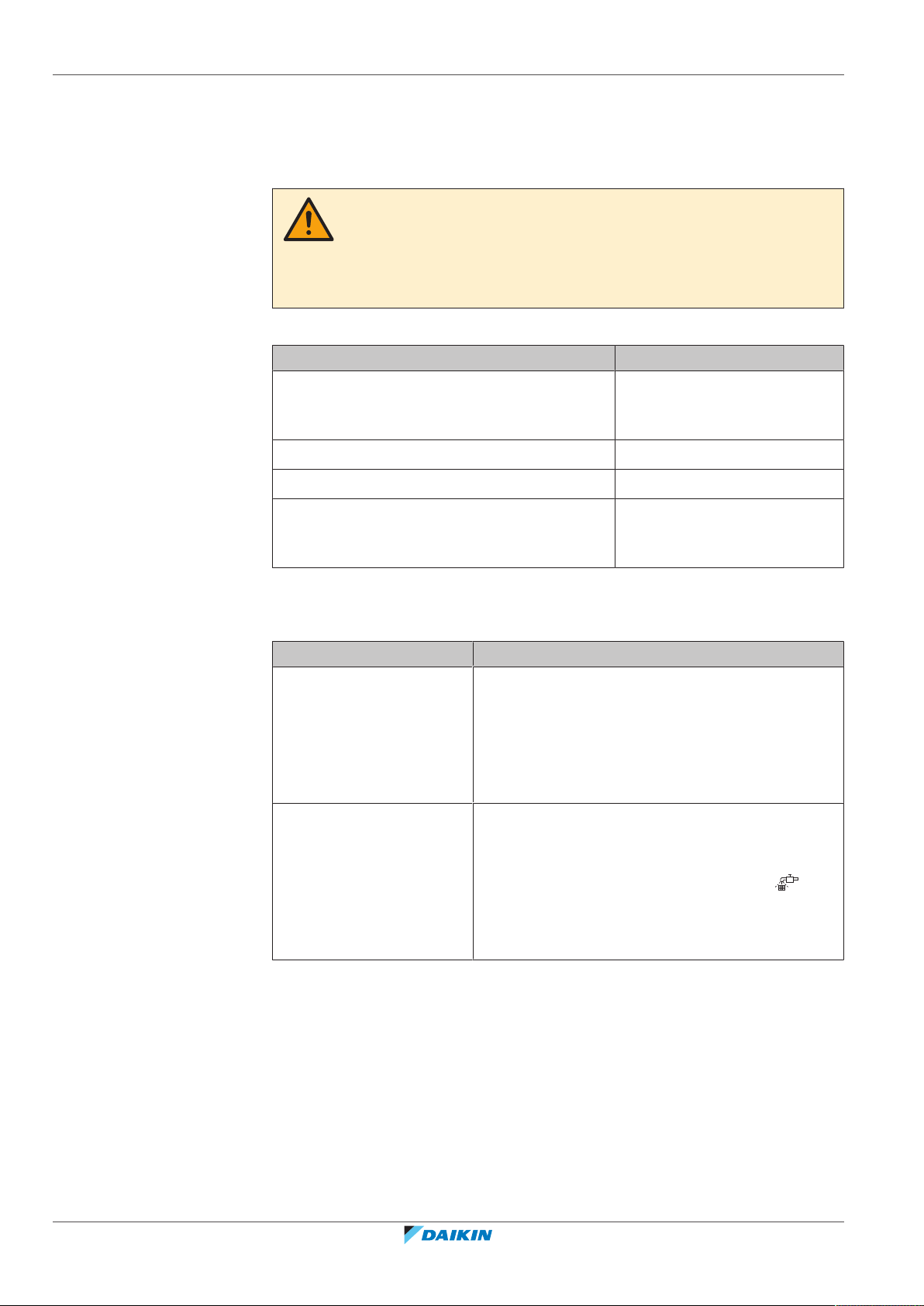
11 | Troubleshooting
11 Troubleshooting
If one of the following malfunctions occur, take the measures shown below and
contact your dealer.
WARNING
Stop operation and shut off the power if anything unusual occurs (burning smells
etc.).
Leaving the unit running under such circumstances may cause breakage, electric
shock or fire. Contact your dealer.
The system MUST be repaired by a qualified service person.
Malfunction Measure
If a safety device such as a fuse, a breaker or an
earth leakage breaker frequently actuates or the
Turn OFF the main power
switch.
ON/OFF switch does NOT properly work.
If water leaks from the unit. Stop the operation.
The operation switch does NOT work well. Turn OFF the power supply.
If the user interface display indicates the unit
number, the operation lamp flashes and the
Notify your installer and report
the malfunction code.
malfunction code appears.
If the system does NOT operate properly except for the above mentioned cases
and none of the above mentioned malfunctions is evident, investigate the system
in accordance with the following procedures.
Malfunction Measure
If the system does not
operate at all.
▪ Check if there is no power failure. Wait until
power is restored. If power failure occurs during
operation, the system automatically restarts
immediately after power is restored.
▪ Check if no fuse has blown or breaker is activated.
Change the fuse or reset the breaker if necessary.
If the system goes into fan
only operation, but as soon
as it goes into heating or
cooling operation, the
system stops.
▪ Check if air inlet or outlet of outdoor or indoor
unit is not blocked by obstacles. Remove any
obstacles and make sure the air can flow freely.
▪ Check if the user interface display shows (time
to clean the air filter). (Refer to "10Maintenance
and service" [4 34] and "Maintenance" in the
indoor unit manual.)
Installer and user reference guide
38
VRV IV-S system air conditioner
RXYSQ4~6T8V/YB
4P482277-1B – 2020.10

11 | Troubleshooting
Malfunction Measure
The system operates but
cooling or heating is
insufficient.
▪ Check if air inlet or outlet of outdoor or indoor
unit is not blocked by obstacles. Remove any
obstacles and make sure the air can flow freely.
▪ Check if the air filter is not clogged (refer to
"Maintenance" in the indoor unit manual).
▪ Check the temperature setting.
▪ Check the fan speed setting on your user
interface.
▪ Check for open doors or windows. Close doors and
windows to prevent wind from coming in.
▪ Check if there are too many occupants in the room
during cooling operation. Check if the heat source
of the room is excessive.
▪ Check if direct sunlight enters the room. Use
curtains or blinds.
▪ Check if the air flow angle is proper.
If after checking all above items, it is impossible to fix the problem yourself, contact
your installer and state the symptoms, the complete model name of the unit (with
manufacturing number if possible) and the installation date (possibly listed on the
warranty card).
In this chapter
11.1 Error codes: Overview ............................................................................................................................................................ 39
11.2 Symptoms that are NOT system malfunctions ...................................................................................................................... 41
11.2.1 Symptom: The system does not operate............................................................................................................... 41
11.2.2 Symptom: Cool/Heat cannot be changed over..................................................................................................... 42
11.2.3 Symptom: Fan operation is possible, but cooling and heating do not work........................................................ 42
11.2.4 Symptom: The fan speed does not correspond to the setting ............................................................................. 42
11.2.5 Symptom: The fan direction does not correspond to the setting ........................................................................ 42
11.2.6 Symptom: White mist comes out of a unit (Indoor unit)...................................................................................... 42
11.2.7 Symptom: White mist comes out of a unit (Indoor unit, outdoor unit)............................................................... 42
11.2.8 Symptom: The user interface reads "U4" or "U5" and stops, but then restarts after a few minutes ................. 43
11.2.9 Symptom: Noise of air conditioners (Indoor unit)................................................................................................. 43
11.2.10 Symptom: Noise of air conditioners (Indoor unit, outdoor unit).......................................................................... 43
11.2.11 Symptom: Noise of air conditioners (Outdoor unit) ............................................................................................. 43
11.2.12 Symptom: Dust comes out of the unit................................................................................................................... 43
11.2.13 Symptom: The units can give off odours ............................................................................................................... 43
11.2.14 Symptom: The outdoor unit fan does not spin ..................................................................................................... 43
11.2.15 Symptom: The compressor in the outdoor unit does not stop after a short heating operation......................... 44
11.2.16 Symptom: The inside of an outdoor unit is warm even when the unit has stopped ........................................... 44
11.2.17 Symptom: Hot air can be felt when the indoor unit is stopped............................................................................ 44
11.1 Error codes: Overview
In case a malfunction code appears on the indoor unit user interface display,
contact your installer and inform the malfunction code, the unit type, and serial
number (you can find this information on the nameplate of the unit).
RXYSQ4~6T8V/YB
VRV IV-S system air conditioner
4P482277-1B – 2020.10
For your reference, a list with malfunction codes is provided. You can, depending
on the level of the malfunction code, reset the code by pushing the ON/OFF
button. If not, ask your installer for advice.
Installer and user reference guide
39
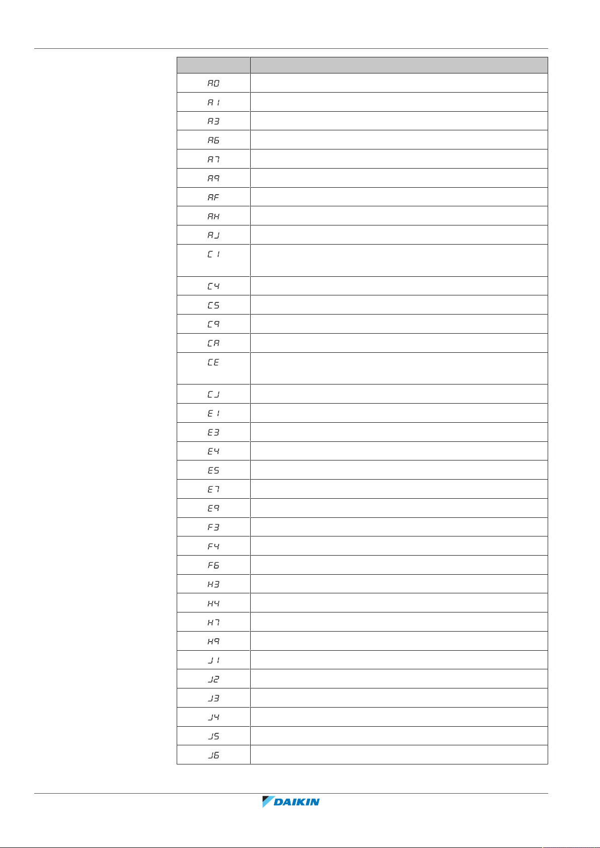
11 | Troubleshooting
Main code Contents
External protection device was activated
EEPROM failure (indoor)
Drain system malfunction (indoor)
Fan motor malfunction (indoor)
Swing flap motor malfunction (indoor)
Expansion valve malfunction (indoor)
Drain malfunction (indoor unit)
Filter dust chamber malfunction (indoor)
Capacity setting malfunction (indoor)
Transmission malfunction between main PCB and sub PCB
(indoor)
Heat exchanger thermistor malfunction (indoor; liquid)
Heat exchanger thermistor malfunction (indoor; gas)
Suction air thermistor malfunction (indoor)
Discharge air thermistor malfunction (indoor)
Movement detector or floor temperature sensor malfunction
(indoor)
User interface thermistor malfunction (indoor)
PCB malfunction (outdoor)
High pressure switch was activated
Low pressure malfunction (outdoor)
Compressor lock detection (outdoor)
Fan motor malfunction (outdoor)
Electronic expansion valve malfunction (outdoor)
Discharge temperature malfunction (outdoor)
Abnormal suction temperature (outdoor)
Refrigerant overcharge detection
High pressure switch malfunction
Low pressure switch malfunction
Fan motor trouble (outdoor)
Installer and user reference guide
40
Ambient temperature sensor malfunction (outdoor)
Pressure sensor malfunction
Current sensor malfunction
Discharge temperature sensor malfunction (outdoor)
Heat exchanger gas temperature sensor malfunction (outdoor)
Suction temperature sensor malfunction (outdoor)
De-icing temperature sensor malfunction (outdoor)
RXYSQ4~6T8V/YB
VRV IV-S system air conditioner
4P482277-1B – 2020.10

Main code Contents
Liquid temperature sensor (after subcool HE) malfunction
(outdoor)
Gas temperature sensor (after subcool HE) malfunction (outdoor)
High pressure sensor malfunction (S1NPH)
Low pressure sensor malfunction (S1NPL)
INV PCB abnormal
Fin temperature abnormal
Inverter PCB faulty
Compressor over current detected
Compressor lock (startup)
Transmission outdoor unit - inverter: INV transmission trouble
INV unbalanced power supply voltage
Fin thermistor malfunction
Capacity setting malfunction (outdoor)
11 | Troubleshooting
Abnormal low pressure drop, faulty expansion valve
Reversed power supply phase malfunction
INV voltage power shortage
System test run not yet executed
Faulty wiring indoor/outdoor
Abnormal user interface - indoor communication
Faulty wiring to outdoor/outdoor
Abnormal main-sub user interface communication
System mismatch. Wrong type of indoor units combined. Indoor
unit malfunction.
Connection malfunction over indoor units or type mismatch
Centralised address duplication
Malfunction in communication centralised control device - indoor
unit
Auto address malfunction (inconsistency)
Auto address malfunction (inconsistency)
11.2 Symptoms that are NOT system malfunctions
11.2.1 Symptom: The system does not operate
RXYSQ4~6T8V/YB
VRV IV-S system air conditioner
4P482277-1B – 2020.10
The following symptoms are NOT system malfunctions:
▪ The air conditioner does not start immediately after the ON/OFF button on the
user interface is pressed. If the operation lamp lights, the system is in normal
condition. To prevent overloading of the compressor motor, the air conditioner
Installer and user reference guide
41

11 | Troubleshooting
11.2.2 Symptom: Cool/Heat cannot be changed over
11.2.3 Symptom: Fan operation is possible, but cooling and heating do not work
starts 5 minutes after it is turned ON again in case it was turned OFF just before.
The same starting delay occurs after the operation mode selector button was
used.
▪ If "Under Centralized Control" is displayed on the user interface, pressing the
operation button causes the display to blink for a few seconds. The blinking
display indicates that the user interface cannot be used.
▪ The system does not start immediately after the power supply is turned on. Wait
one minute until the micro computer is prepared for operation.
▪ When the display shows (change-over under centralized control), it shows
that this is a slave user interface.
▪ When the cool/heat changeover remote control switch is installed and the
display shows (change-over under centralized control), this is because cool/
heat changeover is controlled by the cool/ heat changeover remote control
switch. Ask your dealer where the remote control switch is installed.
Immediately after the power is turned on. The micro computer is getting ready to
operate and is performing a communication check with all indoor units. Please wait
12 minutes maximally until this process is finished.
11.2.4 Symptom: The fan speed does not correspond to the setting
The fan speed does not change even if the fan speed adjustment button is pressed.
During heating operation, when the room temperature reaches the set
temperature, the outdoor unit goes off and the indoor unit changes to whisper fan
speed. This is to prevent cold air blowing directly on occupants of the room. The
fan speed will not change even when another indoor unit is in heating operation, if
the button is pressed.
11.2.5 Symptom: The fan direction does not correspond to the setting
The fan direction does not correspond with the user interface display. The fan
direction does not swing. This is because the unit is being controlled by the micro
computer.
11.2.6 Symptom: White mist comes out of a unit (Indoor unit)
▪ When humidity is high during cooling operation. If the interior of an indoor unit is
extremely contaminated, the temperature distribution inside a room becomes
uneven. It is necessary to clean the interior of the indoor unit. Ask your dealer for
details on cleaning the unit. This operation requires a qualified service person.
11.2.7 Symptom: White mist comes out of a unit (Indoor unit, outdoor unit)
Installer and user reference guide
42
▪ Immediately after the cooling operation stops and if the room temperature and
humidity are low. This is because warm refrigerant gas flows back into the indoor
unit and generates steam.
When the system is changed over to heating operation after defrost operation.
Moisture generated by defrost becomes steam and is exhausted.
RXYSQ4~6T8V/YB
VRV IV-S system air conditioner
4P482277-1B – 2020.10

11 | Troubleshooting
11.2.8 Symptom: The user interface reads "U4" or "U5" and stops, but then restarts after a few minutes
This is because the user interface is intercepting noise from electric appliances
other than the air conditioner. The noise prevents communication between the
units, causing them to stop. Operation automatically restarts when the noise
ceases.
11.2.9 Symptom: Noise of air conditioners (Indoor unit)
▪ A "zeen" sound is heard immediately after the power supply is turned on. The
electronic expansion valve inside an indoor unit starts working and makes the
noise. Its volume will reduce in about one minute.
▪ A continuous low "shah" sound is heard when the system is in cooling operation
or at a stop. When the drain pump (optional accessories) is in operation, this
noise is heard.
▪ A "pishi-pishi" squeaking sound is heard when the system stops after heating
operation. Expansion and contraction of plastic parts caused by temperature
change make this noise.
▪ A low "sah", "choro-choro" sound is heard while the indoor unit is stopped.
When another indoor unit is in operation, this noise is heard. In order to prevent
oil and refrigerant from remaining in the system, a small amount of refrigerant is
kept flowing.
11.2.10 Symptom: Noise of air conditioners (Indoor unit, outdoor unit)
▪ A continuous low hissing sound is heard when the system is in cooling or defrost
operation. This is the sound of refrigerant gas flowing through both indoor and
outdoor units.
▪ A hissing sound which is heard at the start or immediately after stopping
operation or defrost operation. This is the noise of refrigerant caused by flow
stop or flow change.
11.2.11 Symptom: Noise of air conditioners (Outdoor unit)
When the tone of operating noise changes. This noise is caused by the change of
frequency.
11.2.12 Symptom: Dust comes out of the unit
When the unit is used for the first time in a long time. This is because dust has
gotten into the unit.
11.2.13 Symptom: The units can give off odours
The unit can absorb the smell of rooms, furniture, cigarettes, etc., and then emit it
again.
11.2.14 Symptom: The outdoor unit fan does not spin
During operation. The speed of the fan is controlled in order to optimise product
operation.
RXYSQ4~6T8V/YB
VRV IV-S system air conditioner
4P482277-1B – 2020.10
Installer and user reference guide
43

11 | Troubleshooting
11.2.15 Symptom: The compressor in the outdoor unit does not stop after a short heating operation
This is to prevent refrigerant from remaining in the compressor. The unit will stop
after 5 to 10 minutes.
11.2.16 Symptom: The inside of an outdoor unit is warm even when the unit has stopped
This is because the crankcase heater is warming the compressor so that the
compressor can start smoothly.
11.2.17 Symptom: Hot air can be felt when the indoor unit is stopped
Several different indoor units are being run on the same system. When another
unit is running, some refrigerant will still flow through the unit.
Installer and user reference guide
44
VRV IV-S system air conditioner
RXYSQ4~6T8V/YB
4P482277-1B – 2020.10

12 Relocation
Contact your dealer for removing and reinstalling the total unit. Moving units
requires technical expertise.
12 | Relocation
RXYSQ4~6T8V/YB
VRV IV-S system air conditioner
4P482277-1B – 2020.10
Installer and user reference guide
45

13 | Disposal
13 Disposal
This unit uses hydrofluorocarbon. Contact your dealer when discarding this unit.
NOTICE
Do NOT try to dismantle the system yourself: dismantling of the system, treatment of
the refrigerant, oil and other parts MUST comply with applicable legislation. Units
MUST be treated at a specialised treatment facility for reuse, recycling and recovery.
Installer and user reference guide
46
VRV IV-S system air conditioner
RXYSQ4~6T8V/YB
4P482277-1B – 2020.10

14 Technical data
14.1 Information requirements for Eco Design
Follow the steps below to consult the Energy Label – Lot 21 data of the unit and
outdoor/indoor combinations.
1 Open the following webpage: https://energylabel.daikin.eu/
2 To continue, choose:
▪ "Continue to Europe" for the international website.
▪ "Other country" for a country related site.
Result: You are directed to the "Seasonal efficiency" webpage.
3 Under "Eco Design – Ener LOT 21", click "Generate your data".
Result: You are directed to the "Seasonal efficiency (LOT 21)" webpage.
4 Follow the instructions on the webpage to select the correct unit.
Result: When the selection is done, the LOT 21 datasheet can be viewed as a PDF
or a HTML webpage.
14 | Technical data
INFORMATION
Other documents (e.g. manuals, ...) can also be consulted from the resulting
webpage.
RXYSQ4~6T8V/YB
VRV IV-S system air conditioner
4P482277-1B – 2020.10
Installer and user reference guide
47

For the installer
For the installer
Installer and user reference guide
48
VRV IV-S system air conditioner
RXYSQ4~6T8V/YB
4P482277-1B – 2020.10

15 About the box
In this chapter
15.1 About LOOP BY DAIKIN ........................................................................................................................................................... 49
15.2 Overview: About the box........................................................................................................................................................ 49
15.3 Outdoor unit ........................................................................................................................................................................... 50
15.3.1 To unpack the outdoor unit................................................................................................................................... 50
15.3.2 To handle the outdoor unit.................................................................................................................................... 50
15.3.3 To remove the accessories from the outdoor unit ............................................................................................... 51
15.1 About LOOP BY DAIKIN
is part of Daikin's wider commitment to reduce our environmental footprint.
With we want to create a circular economy for refrigerants. One of the actions
to achieve this, is the reuse of reclaimed refrigerant in VRV units produced and sold
in Europe. For more information about the countries that are in scope, visit: http://
www.daikin.eu/loop-by-daikin.
15 | About the box
15.2 Overview: About the box
This chapter describes what you have to do after the box with the outdoor unit is
delivered on-site.
Keep the following in mind:
▪ At delivery, the unit MUST be checked for damage. Any damage MUST be
reported immediately to the claims agent of the carrier.
▪ Bring the packed unit as close as possible to its final installation position to
prevent damage during transport.
▪ Prepare the path along which you want to bring the unit inside in advance.
▪ When handling the unit, take into account the following:
Fragile, handle the unit with care.
Keep the unit upright in order to avoid compressor damage.
RXYSQ4~6T8V/YB
VRV IV-S system air conditioner
4P482277-1B – 2020.10
Installer and user reference guide
49
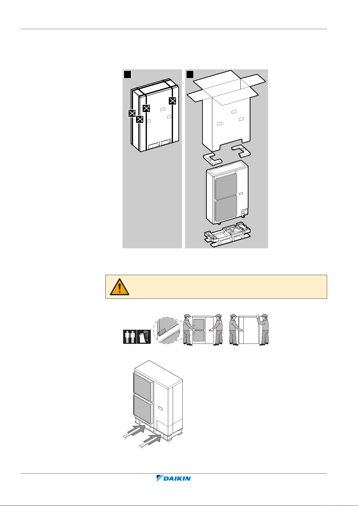
15 | About the box
21
15.3 Outdoor unit
15.3.1 To unpack the outdoor unit
15.3.2 To handle the outdoor unit
CAUTION
To avoid injury, do NOT touch the air inlet or aluminium fins of the unit.
Carry the unit slowly as shown:
Forklift. As long as the unit remains on its pallet, you can also use a forklift.
Installer and user reference guide
50
VRV IV-S system air conditioner
RXYSQ4~6T8V/YB
4P482277-1B – 2020.10
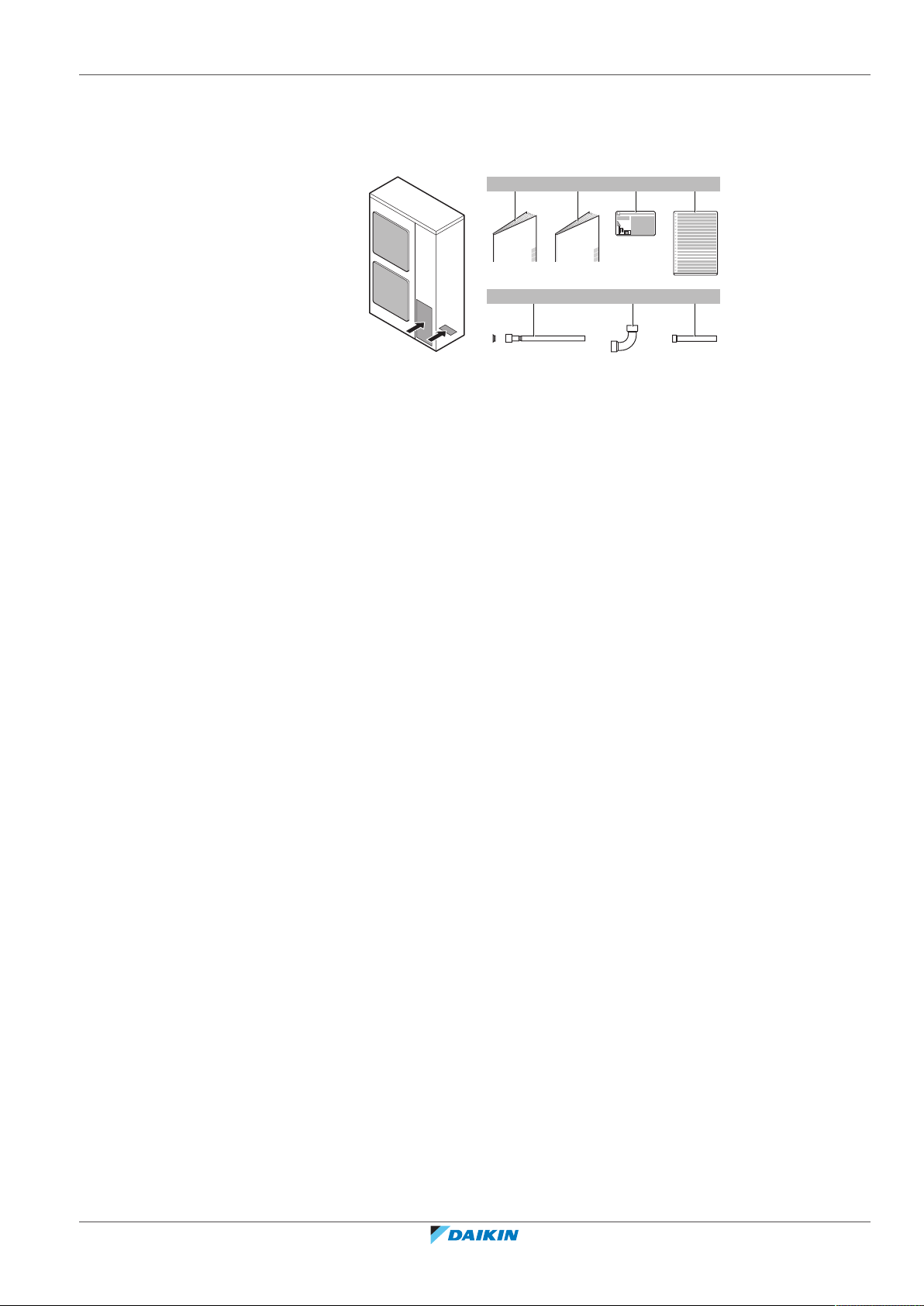
15.3.3 To remove the accessories from the outdoor unit
+
a
1×
b
1×
c
1×
d
1×
e f
1× 1×
g
1×
1 Remove the service cover. See "To open the outdoor unit"[462].
2 Remove the accessories.
a General safety precautions
b Outdoor unit installation and operation manual
c Fluorinated greenhouse gases label
d Multilingual fluorinated greenhouse gases label
e Gas piping accessory 1 + copper gasket (only for RXYSQ6)
f Gas piping accessory 2 (only for RXYSQ6)
g Gas piping accessory 3 (only for RXYSQ6)
15 | About the box
RXYSQ4~6T8V/YB
VRV IV-S system air conditioner
4P482277-1B – 2020.10
Installer and user reference guide
51
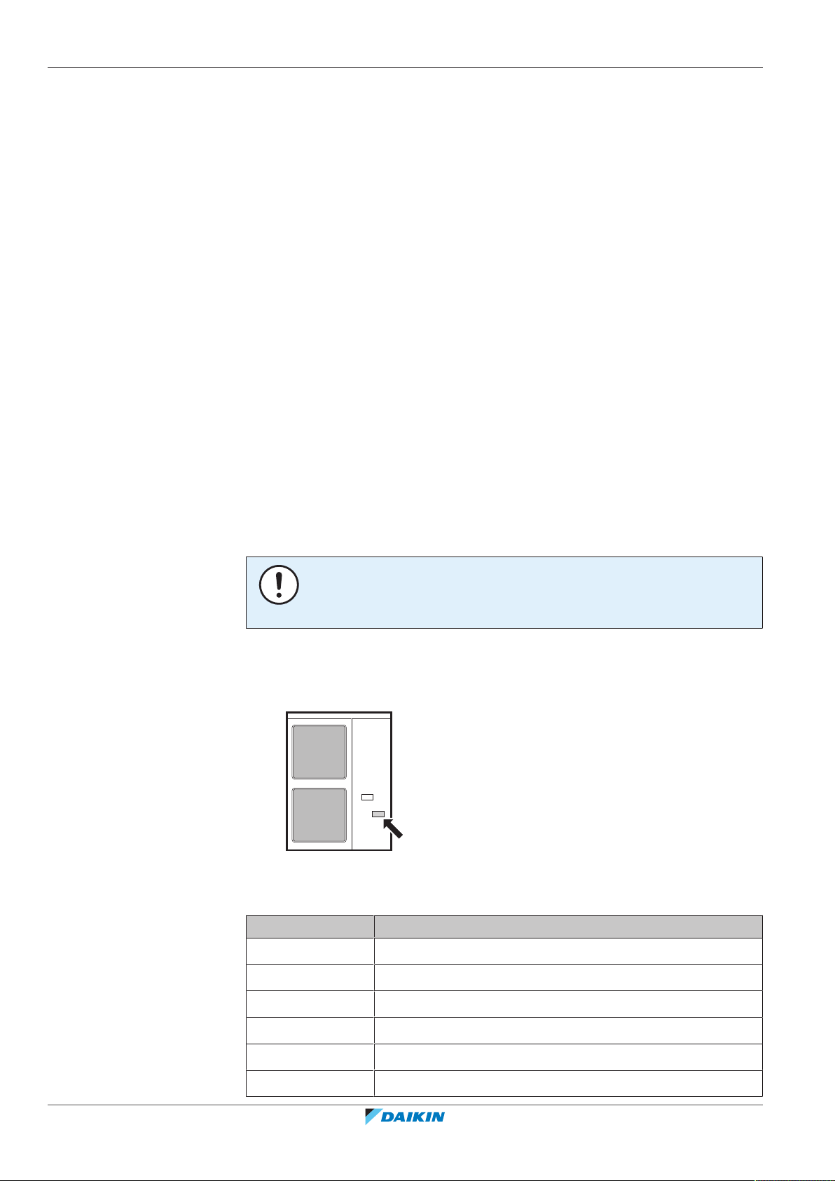
16 | About the units and options
16 About the units and options
In this chapter
16.1 Overview: About the units and options ................................................................................................................................. 52
16.2 Identification........................................................................................................................................................................... 52
16.2.1 Identification label: Outdoor unit.......................................................................................................................... 52
16.3 About the outdoor unit .......................................................................................................................................................... 53
16.4 System layout.......................................................................................................................................................................... 53
16.5 Combining units and options.................................................................................................................................................. 54
16.5.1 About combining units and options....................................................................................................................... 54
16.5.2 Possible combinations of indoor units................................................................................................................... 54
16.5.3 Possible options for the outdoor unit.................................................................................................................... 54
16.1 Overview: About the units and options
This chapter contains information about:
▪ Identification of the outdoor unit.
▪ Where the outdoor unit fits in the system layout.
▪ With which indoor units and options you can combine the outdoor units.
16.2 Identification
NOTICE
When installing or servicing several units at the same time, make sure NOT to switch
the service panels between different models.
16.2.1 Identification label: Outdoor unit
Location
Installer and user reference guide
52
Model identification
Example: R X Y S Q 6 T8 Y B [*]
Code Explanation
R Outdoor air cooled
X Heat pump (no continuous heating)
Y Single module
S S series
Q Refrigerant R410A
4~6 Capacity class
RXYSQ4~6T8V/YB
VRV IV-S system air conditioner
4P482277-1B – 2020.10
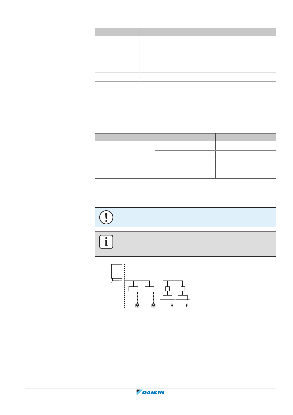
Code Explanation
g
d d
c c
f
e
b
a
g
f
e
T8 VRV IV series
16 | About the units and options
V
Y
B European market
[*] Minor model change indication
16.3 About the outdoor unit
This installation manual concerns the VRV, full inverter driven, heat pump system.
These units are intended for outdoor installation and aimed for air to air heat
pump applications.
Capacity Heating 14.2~18.0kW
Ambient design
temperature
Power supply
Specification RXYSQ4~6
Cooling 12.1~15.5kW
Heating –20~15.5°CWB
Cooling –5~46°CDB
16.4 System layout
NOTICE
Design of the system must not be done at temperatures below –15°C.
INFORMATION
Not all combinations of indoor units are allowed, for guidance, see "Possible
combinations of indoor units"[454].
a VRV IV-S Heat pump outdoor unit
b Refrigerant piping
c VRV direct expansion (DX) indoor unit
d User interface (dedicated depending on indoor unit type)
e BP box (required to connect Residential Air (RA) or Sky Air (SA) direct expansion
(DX) indoor units)
f Residential Air (RA) direct expansion (DX) indoor units
g User interface (wireless, dedicated depending on indoor unit type)
RXYSQ4~6T8V/YB
VRV IV-S system air conditioner
4P482277-1B – 2020.10
Installer and user reference guide
53
16 | About the units and options
16.5 Combining units and options
16.5.1 About combining units and options
The VRV IV-S heat pump system can be combined with several types of indoor
units and is intended for R410A use only.
For an overview which units are available you can consult the product catalogue
for VRV IV-S.
An overview is given indicating the allowed combinations of indoor units and
outdoor units. Not all combinations are allowed. They are subject to rules
(combination between outdoor-indoor, combinations between indoor units, etc.)
mentioned in the technical engineering data.
INFORMATION
Certain options might not be available in your country.
NOTICE
To be sure your system setup (outdoor unit+indoor unit(s)) will work, you have to
consult the latest technical engineering data for the VRV heat pump.
16.5.2 Possible combinations of indoor units
In general following type of indoor units can be connected to a VRV heat pump
system. The list is non-exhaustive and is depending on both outdoor unit model
and indoor unit model combinations.
▪ VRV direct expansion (DX) indoor units (air to air applications).
▪ SA/RA (Sky Air/Residential Air) direct expansion (DX) indoor units (air to air
applications). Further referred to as RA DX indoor units. These indoor units
require a BP box.
▪ AHU (air to air applications): EKEXV-kit+EKEQ-box are required, depending on
application.
▪ Aircurtain (air to air applications): CYV/CAV (Biddle) series, depending on
application.
INFORMATION
▪ Combination of VRVDX and RADX indoor units is not allowed.
▪ Combination of RADX and AHU indoor units is not allowed.
▪ Combination of RADX and aircurtain indoor units is not allowed.
16.5.3 Possible options for the outdoor unit
Installer and user reference guide
54
INFORMATION
Refer to the technical engineering data for the latest option names.
Refrigerant branching kit
Description Model name
Refnet header KHRQ22M29H
RXYSQ4~6T8V/YB
VRV IV-S system air conditioner
4P482277-1B – 2020.10

16 | About the units and options
Description Model name
Refnet joint KHRQ22M20T
For the selection of the optimal branching kit, please refer to "To select refrigerant
branch kits"[469].
Cool/heat selector
In order to control the cooling or heating operation from a central location, the
following option can be connected:
Description RXYSQ4~6_V RXYSQ4~6_Y
Cool/heat selector switch KRC19-26A KRC19-26A
Cool/heat selector PCB EBRP2B —
Cool/heat selector cable — EKCHSC
With optional fixing box
KJB111A KJB111A
for the switch
External control adaptor (DTA104A61/62)
To instruct specific operation with an external input coming from a central control
the external control adaptor can be used. Instructions (group or individual) can be
instructed for low noise operation and power consumption limitation operation.
The external control adapter has to be installed in the indoor unit.
PC configurator cable (EKPCCAB*)
You can make several commissioning field settings through a personal computer
interface. For this option EKPCCAB* is required which is a dedicated cable to
communicate with the outdoor unit. The user interface software is available on
http://www.daikineurope.com/support-and-manuals/software-downloads/.
RXYSQ4~6T8V/YB
VRV IV-S system air conditioner
4P482277-1B – 2020.10
Installer and user reference guide
55
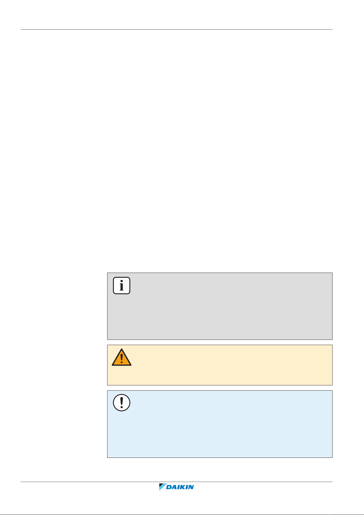
17 | Unit installation
17 Unit installation
In this chapter
17.1 Preparing the installation site
17.1 Preparing the installation site ................................................................................................................................................ 56
17.1.1 Installation site requirements of the outdoor unit ............................................................................................... 56
17.1.2 Additional installation site requirements of the outdoor unit in cold climates ................................................... 59
17.1.3 Securing safety against refrigerant leaks............................................................................................................... 60
17.2 Opening and closing the unit ................................................................................................................................................. 61
17.2.1 About opening the units ........................................................................................................................................ 61
17.2.2 To open the outdoor unit ...................................................................................................................................... 62
17.2.3 To close the outdoor unit....................................................................................................................................... 62
17.3 Mounting the outdoor unit .................................................................................................................................................... 63
17.3.1 About mounting the outdoor unit......................................................................................................................... 63
17.3.2 Precautions when mounting the outdoor unit...................................................................................................... 63
17.3.3 To provide the installation structure..................................................................................................................... 63
17.3.4 To install the outdoor unit..................................................................................................................................... 64
17.3.5 To provide drainage ............................................................................................................................................... 64
17.3.6 To prevent the outdoor unit from falling over...................................................................................................... 65
Do NOT install the unit in places often used as work place. In case of construction
works (e.g. grinding works) where a lot of dust is created, the unit MUST be
covered.
Choose an installation location with sufficient space for carrying the unit in and out
of the site.
17.1.1 Installation site requirements of the outdoor unit
INFORMATION
Also read the following requirements:
▪ General installation site requirements. See the "General safety precautions"
chapter.
▪ Service space requirements. See the "Technical data" chapter.
▪ Refrigerant piping requirements (length, height difference). See further in this
"Preparation" chapter.
CAUTION
Appliance NOT accessible to the general public, install it in a secured area, protected
from easy access.
This unit is suitable for installation in a commercial and light industrial environment.
Installer and user reference guide
56
NOTICE
The equipment described in this manual may cause electronic noise generated from
radio-frequency energy. The equipment complies to specifications that are designed
to provide reasonable protection against such interference. However, there is no
guarantee that interference will not occur in a particular installation.
It is therefore recommended to install the equipment and electric wires in such a
way that they keep a proper distance from stereo equipment, personal computers,
etc.
RXYSQ4~6T8V/YB
VRV IV-S system air conditioner
4P482277-1B – 2020.10
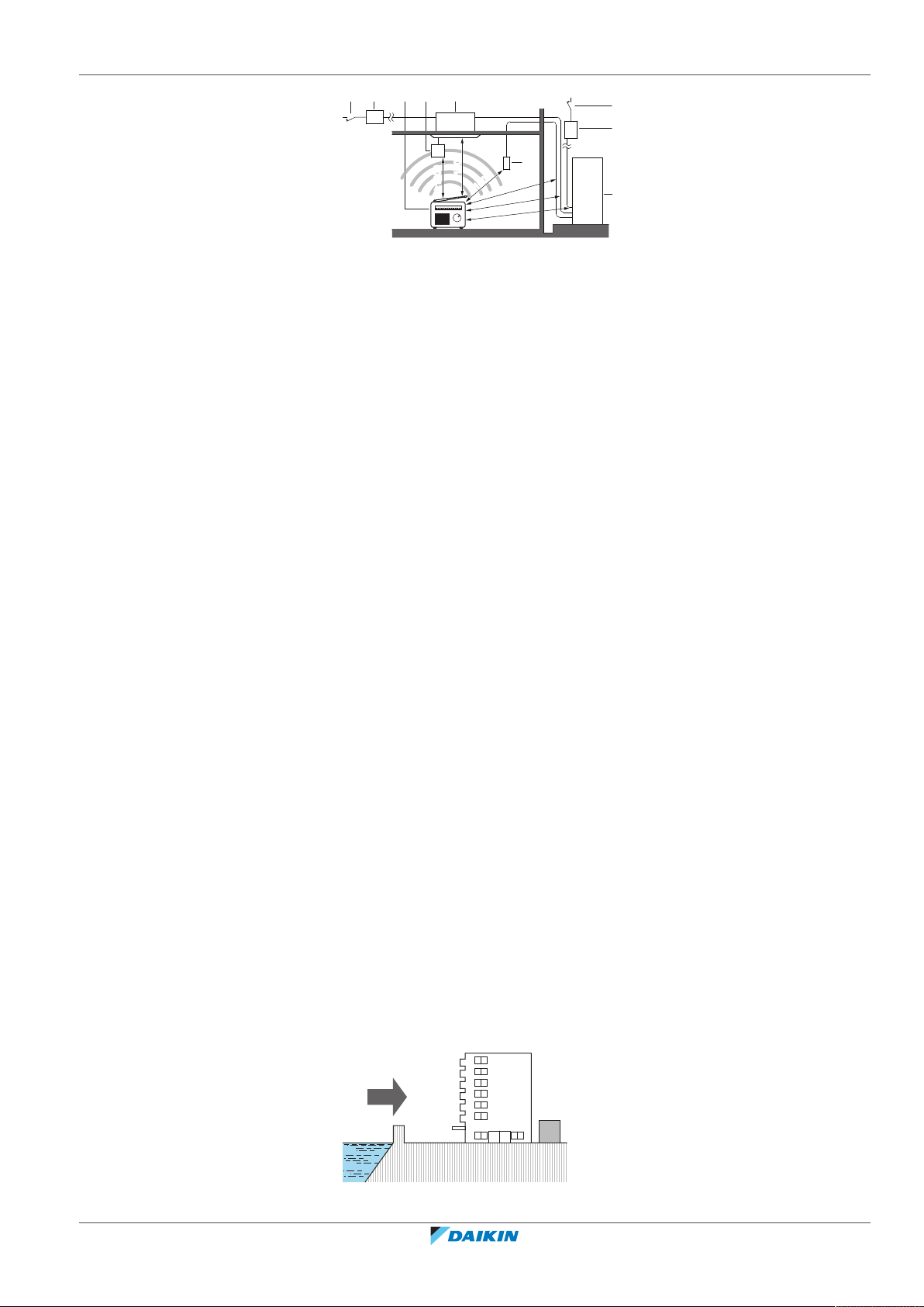
17 | Unit installation
b
bcc
f
ea d
(mm)
≥
1500
≥
1500
≥
1500
≥
1000≥1000
≥
1000≥1000
≥
1000≥1000
d
b
c
a
a Personal computer or radio
b Fuse
c Earth leakage protector
d User interface
e Indoor unit
f Outdoor unit
▪ In places with weak reception, keep distances of 3 m or more to avoid
electromagnetic disturbance of other equipment and use conduit tubes for
power and transmission lines.
▪ Select a place where rain can be avoided as much as possible.
▪ Take care that in the event of a water leak, water cannot cause any damage to
the installation space and surroundings.
▪ Choose a location where the operation noise or the hot/cold air discharged from
the unit will not disturb anyone.
▪ Heat exchanger fins are sharp and injury is possible. Choose an installation
location where there is no risk for injury (especially in areas where children play).
Do NOT install the unit in the following places:
▪ Sound sensitive areas (e.g. near a bedroom), so that the operation noise will
cause no trouble.
Note: If the sound is measured under actual installation conditions, the
measured value might be higher than the sound pressure level mentioned in
Sound spectrum in the data book due to environmental noise and sound
reflections.
▪ In places where a mineral oil mist, spray or vapour may be present in the
atmosphere. Plastic parts may deteriorate and fall off or cause water leakage.
It is NOT recommended to install the unit in the following places because it may
shorten the life of the unit:
▪ Where the voltage fluctuates a lot
▪ In vehicles or vessels
▪ Where acidic or alkaline vapour is present
Seaside installation. Make sure the outdoor unit is NOT directly exposed to sea
winds. This is to prevent corrosion caused by high levels of salt in the air, which
might shorten the life of the unit.
Install the outdoor unit away from direct sea winds.
Example: Behind the building.
RXYSQ4~6T8V/YB
VRV IV-S system air conditioner
4P482277-1B – 2020.10
If the outdoor unit is exposed to direct sea winds, install a windbreaker.
Installer and user reference guide
57

17 | Unit installation
a
b
c
d
c
d
a
a
a
b
▪ Height of windbreaker≥1.5×height of outdoor unit
▪ Mind the service space requirements when installing the windbreaker.
a Sea wind
b Building
c Outdoor unit
d Windbreaker
Strong winds (≥18km/h) blowing against the outdoor unit’s air outlet causes short
circuit (suction of discharge air). This may result in:
▪ deterioration of the operational capacity;
▪ frequent frost acceleration in heating operation;
▪ disruption of operation due to decrease of low pressure or increase of high
pressure;
▪ a broken fan (if a strong wind blows continuously on the fan, it may start rotating
very fast, until it breaks).
It is recommended to install a baffle plate when the air outlet is exposed to wind.
Turn the air outlet side towards the building's wall, fence or screen.
a Make sure there is enough installation space
Set the air outlet side at a right angle to the direction of the wind.
Installer and user reference guide
58
a Prevailing wind direction
b Air outlet
RXYSQ4~6T8V/YB
VRV IV-S system air conditioner
4P482277-1B – 2020.10

17 | Unit installation
a
b
c
c
d
T
AO
(°C WB)
a b
20
15.5
15
10
5
0
–5
–10
–15
–20
10 15 20 25
27
30
T
AI
(°C DB)
17.1.2 Additional installation site requirements of the outdoor unit in cold climates
Protect the outdoor unit against direct snowfall and take care that the outdoor unit
is NEVER snowed up.
a Snow cover or shed
b Pedestal (minimum height = 150mm)
c Prevailing wind direction
d Air outlet
NOTICE
When operating the unit in heating in a low outdoor ambient temperature with high
humidity conditions, make sure to take precautions to keep the drain holes of the
unit free by using proper equipment.
In heating:
RXYSQ4~6T8V/YB
VRV IV-S system air conditioner
4P482277-1B – 2020.10
a Warming up operation range
b Operation range
TAI Ambient indoor temperature
TAO Ambient outdoor temperature
If the unit is selected to operate at ambient temperatures lower than –5°C for 5 days
or longer, with relative humidity levels exceeding 95%, we recommend to apply a
Daikin range specifically designed for such application and/or to contact your dealer
for further advice.
Installer and user reference guide
59

17 | Unit installation
b
a
17.1.3 Securing safety against refrigerant leaks
About safety against refrigerant leaks
About the maximum concentration level
The installer and system specialist shall secure safety against leakage according to
local regulations or standards. The following standards may be applicable if local
regulations are not available.
This system uses R410A as refrigerant. R410A itself is an entirely safe non-toxic,
non-combustible refrigerant. Nevertheless care must be taken to ensure that the
system is installed in a room which is sufficiently large. This assures that the
maximum concentration level of refrigerant gas is not exceeded, in the unlikely
event of major leak in the system and this in accordance to the local applicable
regulations and standards.
The maximum charge of refrigerant and the calculation of the maximum
concentration of refrigerant is directly related to the humanly occupied space in to
which it could leak.
The unit of measurement of the concentration is kg/m3 (the weight in kg of the
refrigerant gas in 1m3 volume of the occupied space).
Compliance to the local applicable regulations and standards for the maximum
allowable concentration level is required.
According to the appropriate European Standard, the maximum allowed
concentration level of refrigerant to a humanly space for R410A is limited to
0.44kg/m3.
a Direction of the refrigerant flow
b Room where refrigerant leak has occurred (outflow of all the refrigerant from the
system)
Pay special attention to places, such as basements etc., where refrigerant can stay,
since refrigerant is heavier than air.
To check the maximum concentration level
Check the maximum concentration level in accordance with steps 1 to 4 below and
take whatever action is necessary to comply.
1 Calculate the amount of refrigerant (kg) charged to each system separately.
Formula A+B=C
Installer and user reference guide
60
A Amount of refrigerant in a single unit system (amount
of refrigerant with which the system is charged before
leaving the factory)
B Additional charging amount (amount of refrigerant
added locally)
C Total amount of refrigerant (kg) in the system
VRV IV-S system air conditioner
RXYSQ4~6T8V/YB
4P482277-1B – 2020.10

17 | Unit installation
a
b
NOTICE
Where a single refrigerant facility is divided into 2 entirely independent refrigerant
systems, use the amount of refrigerant with which each separate system is charged.
2 Calculate the volume of the room (m3) where the indoor unit is installed. In a
case such as the following, calculate the volume of (D), (E) as a single room or
as the smallest room.
D When there are no smaller room divisions:
E When there is a room division that has an opening sufficiently large
to permit free air flow.
a Opening between the rooms. In case there is a door the openings
above and below the door each must be equivalent in size to 0.15%
or more of the floor area.
b Room division
3 Calculate the refrigerant density using the results of the calculations in steps 1
and 2 above. If the result of the above calculation exceeds the maximum
concentration level, a ventilation opening to the adjacent room shall be made.
Formula F/G≤H
F Total volume of refrigerant in the refrigerant system
G Size (m3) of smallest room in which there is an indoor
H Maximum concentration level (kg/m3)
4 Calculate the refrigerant density taking the volume of the room where the
indoor unit is installed and the adjacent room. Install ventilation openings in
the door of adjacent rooms until the refrigerant density is smaller than the
maximum concentration level.
17.2 Opening and closing the unit
unit installed
17.2.1 About opening the units
RXYSQ4~6T8V/YB
VRV IV-S system air conditioner
4P482277-1B – 2020.10
At certain times, you have to open the unit. Example:
▪ When connecting the refrigerant piping
Installer and user reference guide
61

17 | Unit installation
3
45°~90°
(4)
2
1
1×
1
3
2
4
1×
17.2.2 To open the outdoor unit
▪ When connecting the electrical wiring
▪ When maintaining or servicing the unit
DANGER: RISK OF ELECTROCUTION
Do NOT leave the unit unattended when the service cover is removed.
DANGER: RISK OF ELECTROCUTION
DANGER: RISK OF BURNING/SCALDING
Installer and user reference guide
62
17.2.3 To close the outdoor unit
NOTICE
When closing the outdoor unit cover, make sure that the tightening torque does NOT
exceed 4.1N•m.
RXYSQ4~6T8V/YB
VRV IV-S system air conditioner
4P482277-1B – 2020.10

17.3 Mounting the outdoor unit
(mm)
>150
620
350
(345-355)
4× M12
a
20
17.3.1 About mounting the outdoor unit
Typical workflow
Mounting the outdoor unit typically consists of the following stages:
1 Providing the installation structure.
2 Installing the outdoor unit.
3 Providing drainage.
4 Preventing the unit from falling over.
17.3.2 Precautions when mounting the outdoor unit
INFORMATION
Also read the precautions and requirements in the following chapters:
▪ General safety precautions
▪ Preparation
17 | Unit installation
17.3.3 To provide the installation structure
Check the strength and level of the installation ground so that the unit will not
cause any operating vibration or noise.
Fix the unit securely by means of foundation bolts in accordance with the
foundation drawing.
Prepare 4 sets of anchor bolts, nuts and washers (field supply) as follows:
RXYSQ4~6T8V/YB
VRV IV-S system air conditioner
4P482277-1B – 2020.10
a Make sure not to cover the drain holes.
INFORMATION
The recommended height of the upper protruding part of the bolts is 20mm.
Installer and user reference guide
63

17 | Unit installation
a
4× M12
≥150 mm
17.3.4 To install the outdoor unit
NOTICE
Fix the outdoor unit to the foundation bolts using nuts with resin washers (a). If the
coating on the fastening area is stripped off, the metal can rust easily.
17.3.5 To provide drainage
▪ Make sure that condensation water can be evacuated properly.
▪ Install the unit on a base to make sure that there is proper drainage in order to
avoid ice accumulation.
▪ Prepare a water drainage channel around the foundation to drain waste water
away from the unit.
▪ Avoid drain water flowing over the footpath, so that it does NOT become slippery
in case of ambient freezing temperatures.
▪ If you install the unit on a frame, install a waterproof plate within 150mm of the
bottom side of the unit in order to prevent water from getting into the unit and
to avoid drain water dripping (see the following figure).
NOTICE
If drain holes of the outdoor unit are covered by a mounting base or by floor surface,
raise the unit to provide a free space of more than 150mm under the outdoor unit.
Installer and user reference guide
64
RXYSQ4~6T8V/YB
VRV IV-S system air conditioner
4P482277-1B – 2020.10
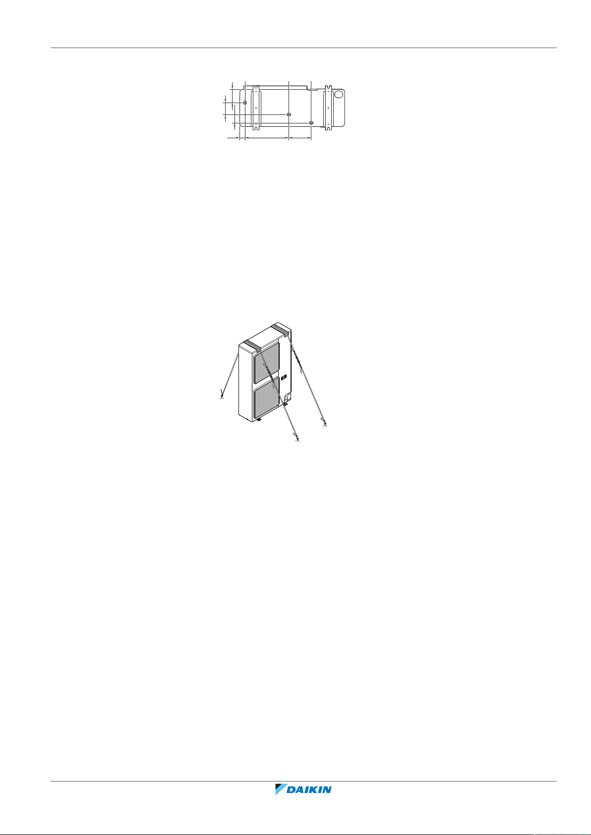
Drain holes (dimensions in mm)
117
102
70
45
376
191
a a a
a Drain holes
17.3.6 To prevent the outdoor unit from falling over
In case the unit is installed in places where strong wind can tilt the unit, take
following measure:
1 Prepare 2 cables as indicated in the following illustration (field supply).
2 Place the 2 cables over the outdoor unit.
3 Insert a rubber sheet between the cables and the outdoor unit to prevent the
cables from scratching the paint (field supply).
4 Attach the ends of the cables.
5 Tighten the cables.
17 | Unit installation
RXYSQ4~6T8V/YB
VRV IV-S system air conditioner
4P482277-1B – 2020.10
Installer and user reference guide
65
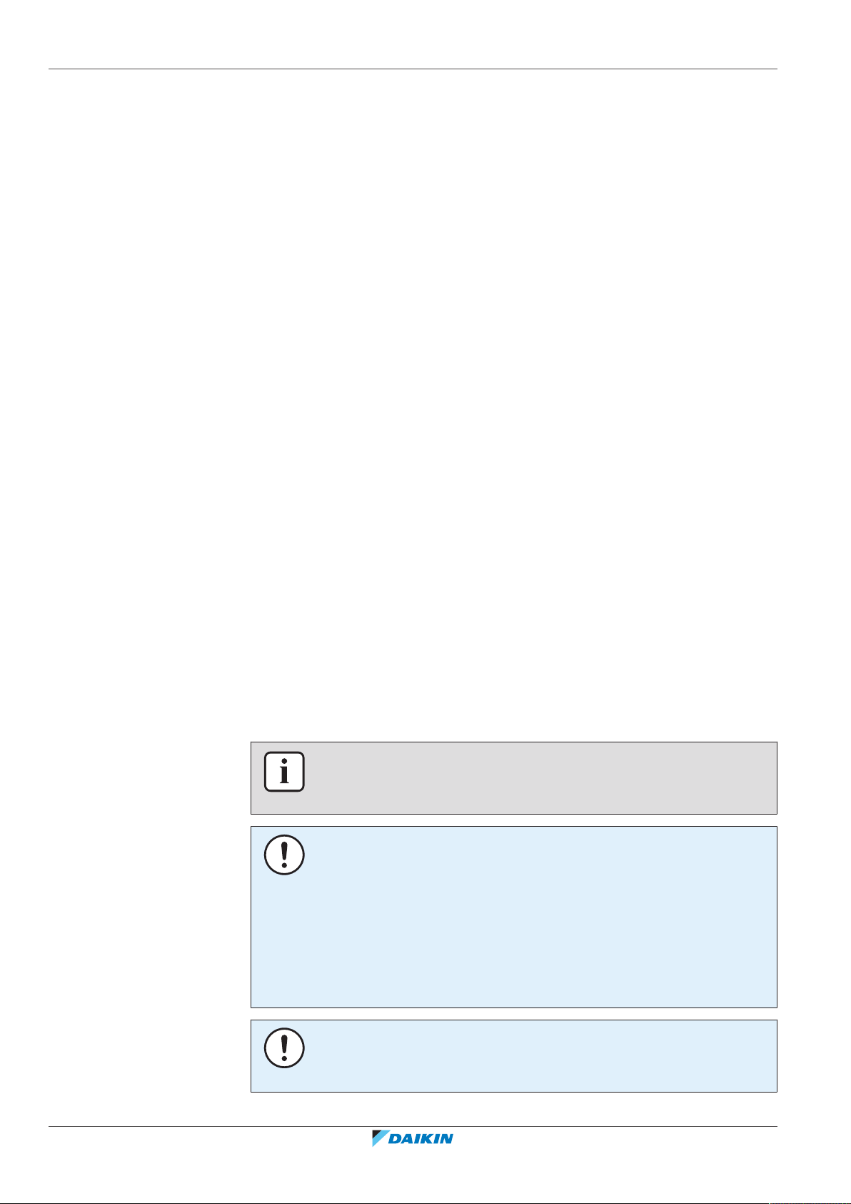
18 | Piping installation
18 Piping installation
In this chapter
18.1 Preparing refrigerant piping ................................................................................................................................................... 66
18.1.1 Refrigerant piping requirements ........................................................................................................................... 66
18.1.2 Refrigerant piping material.................................................................................................................................... 67
18.1.3 To select the piping size......................................................................................................................................... 67
18.1.4 To select refrigerant branch kits............................................................................................................................ 69
18.1.5 Refrigerant piping length and height difference................................................................................................... 70
18.2 Connecting the refrigerant piping .......................................................................................................................................... 71
18.2.1 About connecting the refrigerant piping............................................................................................................... 71
18.2.2 Precautions when connecting the refrigerant piping............................................................................................ 72
18.2.3 Guidelines when connecting the refrigerant piping.............................................................................................. 72
18.2.4 Pipe bending guidelines......................................................................................................................................... 73
18.2.5 To flare the pipe end.............................................................................................................................................. 73
18.2.6 To braze the pipe end ............................................................................................................................................ 74
18.2.7 Using the stop valve and service port.................................................................................................................... 75
18.2.8 To connect the refrigerant piping to the outdoor unit......................................................................................... 76
18.2.9 To connect the refrigerant branching kit .............................................................................................................. 78
18.3 Checking the refrigerant piping.............................................................................................................................................. 79
18.3.1 About checking the refrigerant piping................................................................................................................... 79
18.3.2 Checking refrigerant piping: General guidelines................................................................................................... 80
18.3.3 Checking refrigerant piping: Setup........................................................................................................................ 81
18.3.4 To perform a leak test............................................................................................................................................ 81
18.3.5 To perform vacuum drying .................................................................................................................................... 82
18.3.6 To insulate the refrigerant piping.......................................................................................................................... 82
18.4 Charging refrigerant ............................................................................................................................................................... 83
18.4.1 About charging refrigerant .................................................................................................................................... 83
18.4.2 Precautions when charging refrigerant................................................................................................................. 83
18.4.3 To determine the additional refrigerant amount.................................................................................................. 84
18.4.4 To charge refrigerant ............................................................................................................................................. 85
18.4.5 Error codes when charging refrigerant.................................................................................................................. 87
18.4.6 To fix the fluorinated greenhouse gases label....................................................................................................... 87
18.1 Preparing refrigerant piping
18.1.1 Refrigerant piping requirements
INFORMATION
Also read the precautions and requirements in the "2 General safety
precautions"[48].
NOTICE
The refrigerant R410A requires strict cautions for keeping the system clean, dry and
tight.
▪ Clean and dry: foreign materials (including mineral oils or moisture) should be
prevented from getting mixed into the system.
▪ Tight: R410A does not contain any chlorine, does not destroy the ozone layer,
and does not reduce earth's protection against harmful ultraviolet radiation.
R410A can contribute to the greenhouse effect if it is released. Therefore pay
special attention to check the tightness of the installation.
NOTICE
The piping and other pressure-containing parts shall be suitable for refrigerant. Use
phosphoric acid deoxidised seamless copper for refrigerant.
Installer and user reference guide
66
VRV IV-S system air conditioner
RXYSQ4~6T8V/YB
4P482277-1B – 2020.10

▪ Foreign materials inside pipes (including oils for fabrication) must be
t
Ø
A
B-1 B-2
C-1 C-2 C-3 C-4 E E E E
1 1
3-1 3-2 3-3 3-4
A
D
RA DXVRV DX
D
4
4
5 5 5 5
2 2
2 2
≤30mg/10m.
18.1.2 Refrigerant piping material
▪ Piping material: Phosphoric acid deoxidised seamless copper.
▪ Flare connections: Only use annealed material.
▪ Piping temper grade and thickness:
Outer diameter (Ø) Temper grade Thickness (t)
18 | Piping installation
(a)
6.4mm (1/4")
9.5mm (3/8")
12.7mm (1/2")
15.9mm (5/8") Annealed (O) ≥0.99mm
19.1mm (3/4") Half hard (1/2H) ≥0.80mm
(a)
Depending on the applicable legislation and the maximum working pressure of the unit
(see "PS High" on the unit name plate), larger piping thickness might be required.
18.1.3 To select the piping size
Determine the proper size using the following tables and reference figure (only for
indication).
Annealed (O) ≥0.80mm
INFORMATION
▪ Combination of VRVDX and RADX indoor units is not allowed.
▪ Combination of RADX and AHU indoor units is not allowed.
▪ Combination of RADX and aircurtain indoor units is not allowed.
INFORMATION
If you install RADX indoor units, you have to configure field setting [2‑38] (=type of
installed indoor units). See Mode 2: Field settings.
RXYSQ4~6T8V/YB
VRV IV-S system air conditioner
4P482277-1B – 2020.10
1 Outdoor unit
2 Refrigerant branch kits
3-1~3-4 VRVDX indoor units
4 BP units
5 RADX indoor units
A Piping between outdoor unit and (first) refrigerant branch kit
B-1 B-2 Piping between refrigerant branch kits
C-1~C-4 Piping between refrigerant branch kit and indoor unit
D Piping between refrigerant branch kit and BP unit
E Piping between BP unit and RADX indoor unit
Installer and user reference guide
67
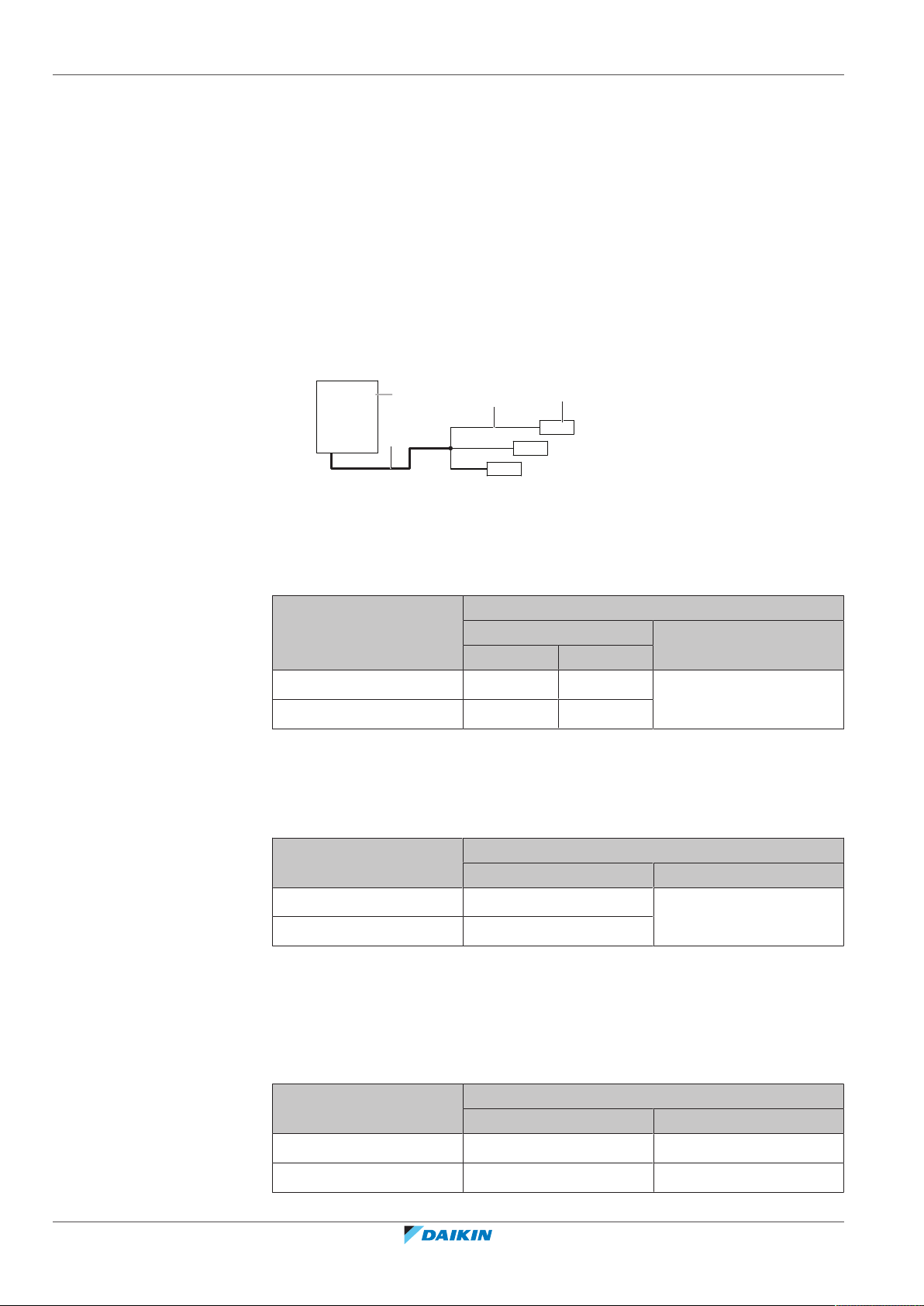
18 | Piping installation
e
d
b
c
a
A: Piping between outdoor unit and (first) refrigerant branch kit
In case the required pipe sizes (inch sizes) are not available, it is also allowed to use
other diameters (mm sizes), taken the following into account:
▪ Select the pipe size nearest to the required size.
▪ Use the suitable adapters for the change-over from inch to mm pipes (field
supply).
▪ The additional refrigerant calculation has to be adjusted as mentioned in "To
determine the additional refrigerant amount"[484].
When the equivalent pipe length between outdoor unit and the furthest indoor
unit is 90 m or more (b+d), the size of the main gas pipe (b) must be increased
(size-up). If the recommended gas pipe (size-up) is not available, you must use the
standard size (which might result in a small capacity decrease).
a Outdoor unit
b Main gas pipe (increase piping size if length b+d≥90m)
c First refrigerant branch kit
d Piping between indoor unit and first refrigerant branch kit
e Furthest indoor unit
Outdoor unit capacity
type (HP)
Piping outer diameter size (mm)
Gas pipe Liquid pipe
Standard Size-up
4+5 15.9 19.1 9.5
6 19.1 22.2
B: Piping between refrigerant branch kits
Choose from the following table in accordance with the indoor unit total capacity
type, connected downstream. Do not let the connection piping exceed the
refrigerant piping size chosen by the general system model name.
Indoor unit capacity index Piping outer diameter size (mm)
Gas pipe Liquid pipe
<150 15.9 9.5
150≤x≤182 19.1
Example: Downstream capacity for B-1 = capacity index of unit 3-1 + capacity index
of unit 3-2
C: Piping between refrigerant branch kit and indoor unit
Use the same diameters as the connections (liquid, gas) on the indoor units. The
diameters of the indoor units are as follows:
Installer and user reference guide
68
Indoor unit capacity index Piping outer diameter size (mm)
Gas pipe Liquid pipe
15~50 12.7 6.4
63~140 15.9 9.5
VRV IV-S system air conditioner
RXYSQ4~6T8V/YB
4P482277-1B – 2020.10
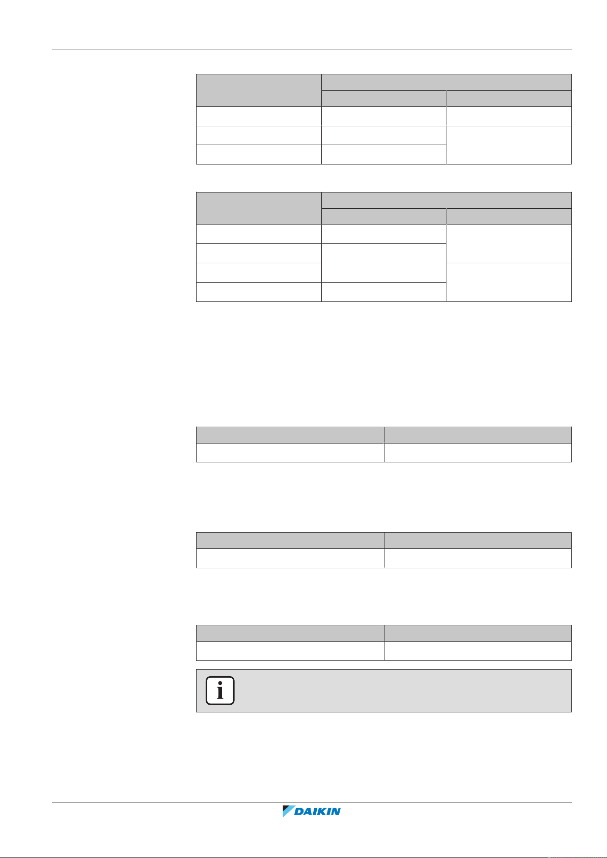
D: Piping between refrigerant branch kit and BP unit
18 | Piping installation
Total capacity index of
connected indoor units
15~62 12.7 6.4
63~149 15.9 9.5
150~182 19.1
E: Piping between BP unit and RA DX indoor unit
Indoor unit capacity index Piping outer diameter size (mm)
15~42 9.5 6.4
50 12.7
60 9.5
71 15.9
18.1.4 To select refrigerant branch kits
For piping example, refer to "To select the piping size"[467].
Refnet joint at first branch (counting from outdoor unit)
Piping outer diameter size (mm)
Gas pipe Liquid pipe
Gas pipe Liquid pipe
When using refnet joints at the first branch counted from the outdoor unit side,
choose from the following table in accordance with the capacity of the outdoor
unit. Example: Refnet joint A→B‑1.
Outdoor unit capacity type (HP) Refrigerant branch kit
4~6 KHRQ22M20T
Refnet joints at other branches
For refnet joints other than the first branch, select the proper branch kit model
based on the total capacity index of all indoor units connected after the refrigerant
branch. Example: Refnet joint B‑1→C‑1.
Indoor unit capacity index Refrigerant branch kit
<182 KHRQ22M20T
Refnet headers
Concerning refnet headers, choose from the following table in accordance with the
total capacity of all the indoor units connected below the refnet header.
Indoor unit capacity index Refrigerant branch kit
<182 KHRQ22M29H
INFORMATION
Maximum 8 branches can be connected to a header.
RXYSQ4~6T8V/YB
VRV IV-S system air conditioner
4P482277-1B – 2020.10
Installer and user reference guide
69

18 | Piping installation
18.1.5 Refrigerant piping length and height difference
The piping lengths and height differences must comply with the following requirements. Two patterns will be
discussed:
• Outdoor with 100% VRVDX indoor units
• Outdoor with 100% RADX indoor units
Requirement Limit
VRVDX RADX
Maximum actual piping length
▪ Example 1.1, unit8: a+b+c+d+e+f+g+p≤Limit
▪ Example 1.2, unit6: a+b+h≤Limit
▪ Example 1.2, unit8: a+i+k≤Limit
▪ Example 1.3, unit8: a+i≤Limit
▪ Example 2, unit18: a+b+m≤Limit
Maximum equivalent piping length
(a)
Maximum total piping length
▪ Example 1.1: a+b+c+d+e+f+g+h+i+j+k+l+m+n+p≤Limit
▪ Example 2: a+b+c+d+e+f+g+h+i+j+k+l+m≤Limit
Minimum length outdoor-first refrigerant branch kit
▪ Example 2: Limit≤a
Maximum length first branch kit-indoor unit
▪ Example 1.1, unit8: b+c+d+e+f+g+p≤Limit
▪ Example 1.2, unit6: b+h≤Limit
▪ Example 1.2, unit8: i+k≤Limit
▪ Example 1.3, unit8: i≤Limit
120m 65m
150m 85m
300m 140m
N/A 5m
40m 40m
▪ Example 2, unit18: b+m≤Limit
Maximum length outdoor-BP
▪ Example 2, BP3: a+b≤Limit
Minimum and maximum length BPindoor
▪ Example 2, unit 18: Min.≤m≤Max.
Maximum height difference
outdoor-indoor
Indoor unit capacity index<60 N/A 2~15m
Indoor unit capacity index=60 N/A 2~12m
Indoor unit capacity index=71 N/A 2~8m
Outdoor higher than indoor
▪ Examples: H1≤Limit
Outdoor lower than indoor 40m
Maximum height difference indoor-indoor
▪ Examples: H2≤Limit
Maximum height difference outdoor-BP
▪ Example 2: H3≤Limit
Maximum height difference BP-BP
▪ Example 2: H4≤Limit
Maximum height difference BP-indoor
N/A 55m
50m 30m
15m 15m
N/A 30m
N/A 15m
N/A 5m
▪ Example 2: H5≤Limit
Installer and user reference guide
70
VRV IV-S system air conditioner
RXYSQ4~6T8V/YB
4P482277-1B – 2020.10
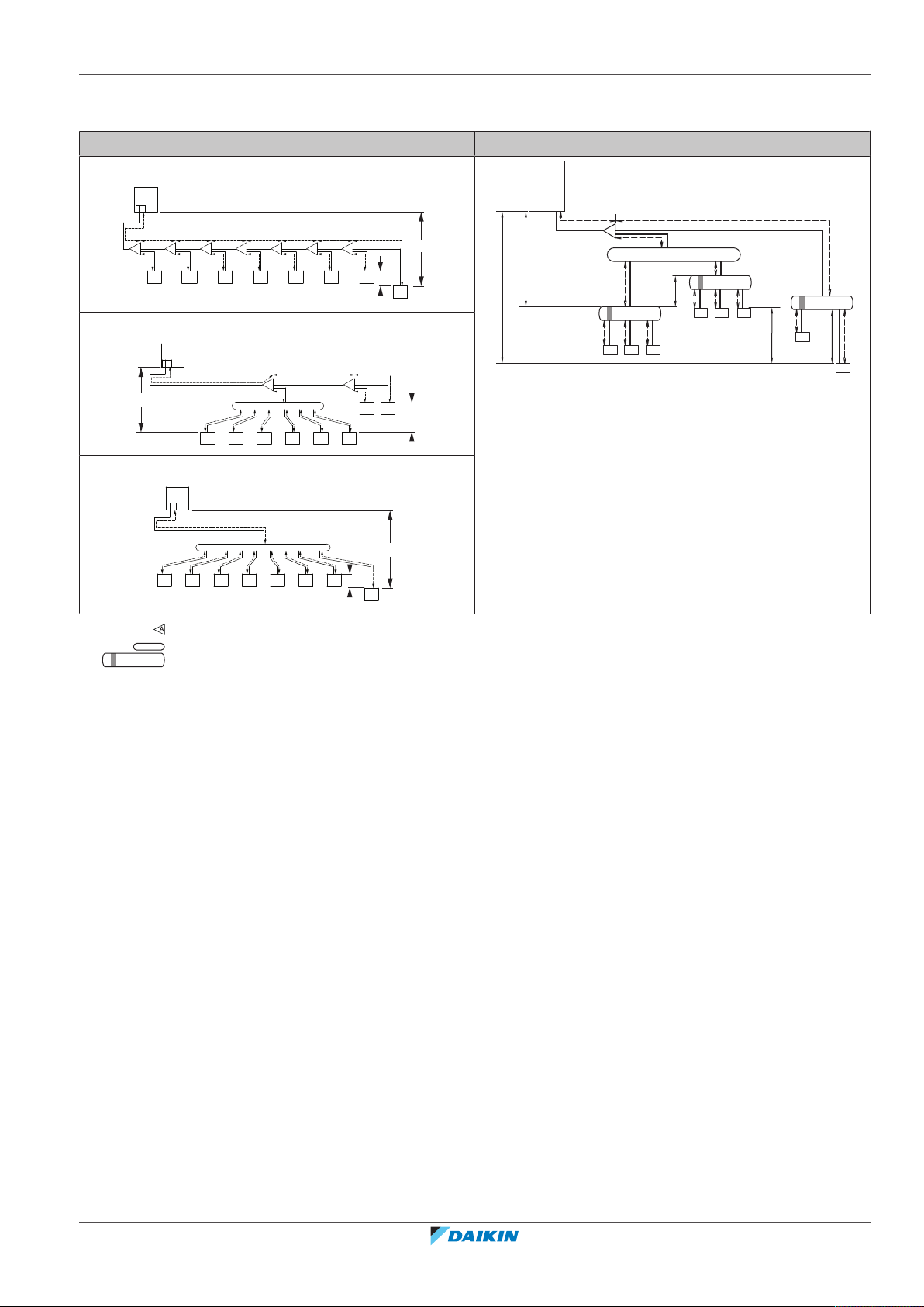
18 | Piping installation
a
A
h i j k l m n
B C D E F G
pb c d e f
1 2 3 4 5 6 7
8
g
H1
H2
H3
a
c
d
f
H1
BP1
g
h
b
A
l
m
BP3
18
17
131211
H4
e
i
BP2
j
k
161514
H2
H5
a
b
c d e f
i
k
j
g h
A B
1 2 3 4 5 6
7 8
H1
H2
a
c
b d e fig h
1 2 3 4 5 6 7
8
H1
H2
(a)
Assume equivalent piping length of refnet joint=0.5m and refnet header=1m (for calculation purposes of equivalent piping
length, not for refrigerant charge calculations).
Example 1 (VRVDX indoor units) Example 2 (RADX indoor units)
Example 1.1
Example 1.2
Example 1.3
Refnet joint
Refnet header
BP box
1~8 VRVDX indoor units
11~18 RADX indoor units
18.2 Connecting the refrigerant piping
18.2.1 About connecting the refrigerant piping
Before connecting the refrigerant piping
Make sure the outdoor and indoor units are mounted.
Typical workflow
Connecting the refrigerant piping involves:
▪ Connecting the refrigerant piping to the outdoor unit
▪ Connecting refrigerant branch kits
▪ Connecting the refrigerant piping to the indoor units (see the installation manual
of the indoor units)
▪ Insulating the refrigerant piping
RXYSQ4~6T8V/YB
VRV IV-S system air conditioner
4P482277-1B – 2020.10
▪ Keeping in mind the guidelines for:
- Pipe bending
- Flaring pipe ends
- Brazing
- Using the stop valves
Installer and user reference guide
71
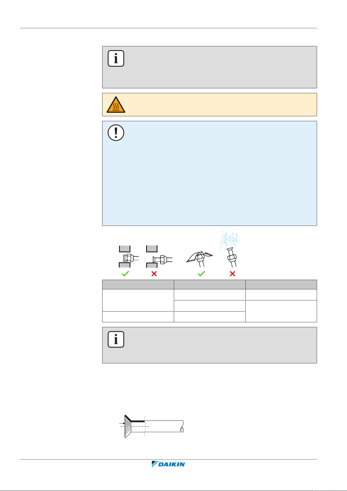
18 | Piping installation
18.2.2 Precautions when connecting the refrigerant piping
INFORMATION
Also read the precautions and requirements in the following chapters:
▪ General safety precautions
▪ Preparation
DANGER: RISK OF BURNING/SCALDING
NOTICE
Take the following precautions on refrigerant piping into account:
▪ Avoid anything but the designated refrigerant to get mixed into the refrigerant
cycle (e.g. air).
▪ Only use R410A when adding refrigerant.
▪ Only use installation tools (e.g. manifold gauge set) that are exclusively used for
R410A installations to withstand the pressure and to prevent foreign materials
(e.g. mineral oils and moisture) from mixing into the system.
▪ Install the piping so that the flare is NOT subjected to mechanical stress
▪ Protect the piping as described in the following table to prevent dirt, liquid or
dust from entering the piping.
▪ Use caution when passing copper tubes through walls (see figure below).
Unit Installation period Protection method
Outdoor unit >1month Pinch the pipe
<1month Pinch or tape the pipe
Indoor unit Regardless of the period
INFORMATION
Do NOT open the refrigerant stop valve before checking the refrigerant piping. When
you need to charge additional refrigerant it is recommended to open the refrigerant
stop valve after charging.
18.2.3 Guidelines when connecting the refrigerant piping
Take the following guidelines into account when connecting pipes:
▪ Coat the flare inner surface with ether oil or ester oil when connecting a flare
nut. Tighten 3 or 4 turns by hand, before tightening firmly.
▪ ALWAYS use 2 wrenches together when loosening a flare nut.
Installer and user reference guide
72
VRV IV-S system air conditioner
RXYSQ4~6T8V/YB
4P482277-1B – 2020.10
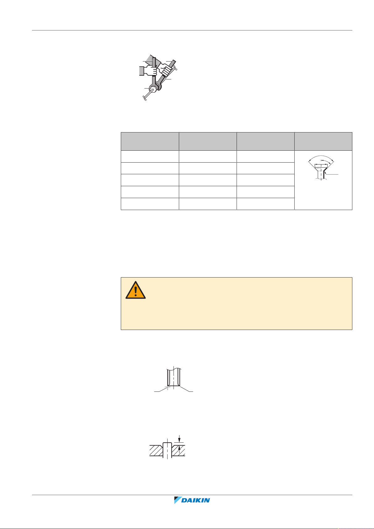
18 | Piping installation
a
b
c
d
R=
0.4~0.8
±2
45°
90°
±2
ØA
a b
A
▪ ALWAYS use a spanner and torque wrench together to tighten the flare nut when
connecting the piping. This to prevent nut cracking and leaks.
a Torque wrench
b Spanner
c Piping union
d Flare nut
Piping size (mm) Tightening torque
(N•m)
Ø6.4 15~17 8.7~9.1
Ø9.5 33~39 12.8~13.2
Ø12.7 50~60 16.2~16.6
Ø15.9 62~75 19.3~19.7
Ø19.1 90~110 23.6~24.0
Flare dimensions
(A) (mm)
Flare shape (mm)
18.2.4 Pipe bending guidelines
Use a pipe bender for bending. All pipe bends should be as gentle as possible
(bending radius should be 30~40 mm or larger).
18.2.5 To flare the pipe end
1 Cut the pipe end with a pipe cutter.
2 Remove burrs with the cut surface facing down so that the chips do NOT enter
the pipe.
3 Remove the flare nut from the stop valve and put the flare nut on the pipe.
CAUTION
▪ Incomplete flaring may cause refrigerant gas leakage.
▪ Do NOT re-use flares. Use new flares to prevent refrigerant gas leakage.
▪ Use flare nuts that are included with the unit. Using different flare nuts may
cause refrigerant gas leakage.
a Cut exactly at right angles.
b Remove burrs.
RXYSQ4~6T8V/YB
VRV IV-S system air conditioner
4P482277-1B – 2020.10
4 Flare the pipe. Set exactly at the position as shown in the following figure.
Installer and user reference guide
73

18 | Piping installation
a b
c
1
1
≤Ø25.4
a b c d e
f
f
A 0~0.5mm 1.0~1.5mm 1.5~2.0mm
5 Check that the flaring is properly made.
18.2.6 To braze the pipe end
Flare tool for R410A
(clutch type)
(Ridgid-type)
a Flare’s inner surface MUST be flawless.
b The pipe end MUST be evenly flared in a perfect circle.
c Make sure the flare nut is fitted.
Conventional flare tool
Clutch type
Wing nut type
(Imperial-type)
NOTICE
Precautions when connecting field piping. Add brazing material as shown in the
figure.
▪ When brazing, blow through with nitrogen to prevent creation of large quantities
of oxidised film on the inside of the piping. This film adversely affects valves and
compressors in the refrigerating system and prevents proper operation.
▪ Set the nitrogen pressure to 20kPa (0.2bar) (just enough so it can be felt on the
skin) with a pressure-reducing valve.
a Refrigerant piping
b Part to be brazed
c Taping
d Manual valve
e Pressure-reducing valve
f Nitrogen
▪ Do NOT use anti-oxidants when brazing pipe joints.
Residue can clog pipes and break equipment.
▪ Do NOT use flux when brazing copper-to-copper refrigerant piping. Use phosphor
copper brazing filler alloy (BCuP), which does not require flux.
Flux has an extremely harmful influence on refrigerant piping systems. For
instance, if chlorine based flux is used, it will cause pipe corrosion or, in
particular, if the flux contains fluorine, it will deteriorate the refrigerant oil.
Installer and user reference guide
74
▪ Always protect the surrounding surfaces (e.g. insulation foam) from heat when
brazing.
RXYSQ4~6T8V/YB
VRV IV-S system air conditioner
4P482277-1B – 2020.10

18.2.7 Using the stop valve and service port
c
d
a
b
a b
cde
To handle the stop valve
Take the following guidelines into account:
▪ Make sure to keep all stop valves open during operation.
▪ The gas and liquid stop valves are factory closed.
▪ The figures below show the name of each part required in handling the stop
valve.
a Service port and service port cover
b Stop valve
c Field piping connection
d Stop valve cover
18 | Piping installation
a Service port
b Stop valve cover
c Hexagon hole
d Shaft
e Valve seat
▪ Do NOT apply excessive force to the stop valve. Doing so may break the valve
body.
To open/close the stop valve
Result: The valve is now open/closed.
To handle the stop valve cover
▪ The stop valve cover is sealed where indicated by the arrow. Do NOT damage it.
▪ After handling the stop valve, tighten the stop valve cover securely, and check for
refrigerant leaks. For the tightening torque, refer to the table below.
Counterclockwise to open
Clockwise to close
RXYSQ4~6T8V/YB
VRV IV-S system air conditioner
4P482277-1B – 2020.10
Installer and user reference guide
75

18 | Piping installation
c
a
b
d
a
b
c
d
To handle the service port
Tightening torques
▪ Always use a charge hose equipped with a valve depressor pin, since the service
port is a Schrader type valve.
▪ After handling the service port, make sure to tighten the service port cover
securely. For the tightening torque, refer to the table below.
▪ Check for refrigerant leaks after tightening the service port cover.
Stop valve size
Tightening torque N•m (turn clockwise to close)
(mm)
Valve body Hexagonal
wrench
Ø9.5 5.4~6.6 4mm 13.5~16.5 11.5~13.9
Ø15.9 13.5~16.5 6mm 22.5~27.5
18.2.8 To connect the refrigerant piping to the outdoor unit
NOTICE
Be sure that the field installed piping does not touch other pipes, the bottom panel
or side panel. Especially for the bottom and side connection, be sure to protect the
piping with suitable insulation, to prevent it from coming into contact with the
casing.
1 Do the following:
▪ Remove the service cover (a) with screw (b).
▪ Remove the piping intake plate (c) with screw (d).
Shaft
Cap (valve lid) Service port
2 Choose a piping route (a, b, c or d).
Installer and user reference guide
76
VRV IV-S system air conditioner
RXYSQ4~6T8V/YB
4P482277-1B – 2020.10

18 | Piping installation
b b bb
a
a
a
b
A
e1 ecdf
A
c
d e f
INFORMATION
▪ Remove the knockout hole (a) in the bottom plate or cover plate by tapping on
the attachment points with a flat head screwdriver and a hammer.
▪ Optionally, cut out the slits (b) with a metal saw.
NOTICE
Precautions when making knockout holes:
▪ Avoid damaging the casing and underlying piping.
▪ After making the knockout holes, we recommend to remove the burrs and paint
the edges and areas around the edges using repair paint to prevent rusting.
▪ When passing electrical wiring through the knockout holes, wrap the wiring with
protective tape to prevent damage.
3 Do the following:
▪ Connect the liquid pipe (a) to the liquid stop valve.
▪ Connect the gas pipe (b) to the gas stop valve.
▪ In case of RXYSQ6: Connect the gas piping accessories (c, c1, d, e), and cut
them to the required length (e1). This is necessary because the size of the
gas stop valve is Ø15.9 while the piping between outdoor unit and first
refrigerant branch kit is Ø19.1.
Possibility 1: To the front
Possibility 2: To the back
RXYSQ4~6T8V/YB
VRV IV-S system air conditioner
4P482277-1B – 2020.10
Installer and user reference guide
77

18 | Piping installation
A
c
d e1 e f
A
c
e1
f
e
A
c1
c
a
Possibility 3: To the side
c, c1 Gas piping accessory 1 + copper gasket (always use it)
d Gas piping accessory 2
e, e1 Gas piping accessory 3 (cut it to the required length)
f Field supply
Possibility 4: Downwards
4 Reattach the service cover and the piping intake plate.
5 Seal all gaps (example: a) to prevent snow and small animals from entering the
system.
WARNING
Provide adequate measures to prevent that the unit can be used as a shelter by small
animals. Small animals that make contact with electrical parts can cause
malfunctions, smoke or fire.
NOTICE
Make sure to open the stop valves after installing the refrigerant piping and
performing vacuum drying. Running the system with the stop valves closed may
break the compressor.
18.2.9 To connect the refrigerant branching kit
For installation of the refrigerant branching kit, refer to the installation manual
delivered with the kit.
Installer and user reference guide
78
▪ Mount the refnet joint so that it branches either horizontally or vertically.
▪ Mount the refnet header so that it branches horizontally.
RXYSQ4~6T8V/YB
VRV IV-S system air conditioner
4P482277-1B – 2020.10

A
B
±
3
0
°
a
b
c
a
a Horizontal surface
Refrigerant piping works are
finished?
The indoor units and/or
outdoor unit were already
powered ON?
Use procedure:
"Method 2: After power ON".
Finish piping work.
Use procedure:
"Method 1: Before power ON
(regular method)".
Yes
No
No
Yes
b Refnet joint mounted vertically
c Refnet joint mounted horizontally
18.3 Checking the refrigerant piping
18 | Piping installation
18.3.1 About checking the refrigerant piping
It is very important that all refrigerant piping work is done before the units
(outdoor or indoor) are powered on. When the units are powered on, the
expansion valves will initialise. This means that the valves will close.
NOTICE
Leak test and vacuum drying of field piping and indoor units is impossible when field
expansion valves are closed.
RXYSQ4~6T8V/YB
VRV IV-S system air conditioner
4P482277-1B – 2020.10
Method 1: Before power ON
If the system has not yet been powered on, no special action is required to
perform the leak test and the vacuum drying.
Method 2: After power ON
If the system has already been powered on, activate setting [2‑21] (refer to "To
access mode 1 or 2" [4 101]). This setting will open field expansion valves to
guarantee a refrigerant piping pathway and make it possible to perform the leak
test and the vacuum drying.
Installer and user reference guide
79
18 | Piping installation
DANGER: RISK OF ELECTROCUTION
NOTICE
Make sure that all indoor units connected to the outdoor unit are powered on.
NOTICE
Wait to apply setting [2‑21] until the outdoor unit has finished the initialisation.
Leak test and vacuum drying
Checking the refrigerant piping involves:
▪ Checking for any leakages in the refrigerant piping.
▪ Performing vacuum drying to remove all moisture, air or nitrogen in the
refrigerant piping.
If there is a possibility of moisture being present in the refrigerant piping (for
example, water may have entered the piping), first carry out the vacuum drying
procedure below until all moisture has been removed.
All piping inside the unit has been factory tested for leaks.
Only field installed refrigerant piping needs to be checked. Therefore, make sure
that all the outdoor unit stop valves are firmly closed before performing leak test
or vacuum drying.
NOTICE
Make sure that all (field supplied) field piping valves are OPEN (not outdoor unit stop
valves!) before you start leak test and vacuuming.
For more information on the state of the valves, refer to "Checking refrigerant
piping: Setup"[481].
18.3.2 Checking refrigerant piping: General guidelines
Connect the vacuum pump through a manifold to the service port of all stop valves
to increase efficiency (refer to "Checking refrigerant piping: Setup"[481]).
NOTICE
Use a 2-stage vacuum pump with a non-return valve or a solenoid valve that can
evacuate to a gauge pressure of –100.7kPa (−1.007bar)(5Torr absolute).
Installer and user reference guide
80
NOTICE
Make sure the pump oil does not flow oppositely into the system while the pump is
not working.
NOTICE
Do NOT purge the air with refrigerants. Use a vacuum pump to evacuate the
installation.
RXYSQ4~6T8V/YB
VRV IV-S system air conditioner
4P482277-1B – 2020.10

18.3.3 Checking refrigerant piping: Setup
p<p
>
N2
C
b c e
a
g
f
d
A B
a Pressure reducing valve
b Nitrogen
c Weighing scales
d Refrigerant R410A tank (siphon system)
e Vacuum pump
f Liquid line stop valve
g Gas line stop valve
A Valve A
B Valve B
C Valve C
Valve State of valve
Valve A Open
Valve B Open
Valve C Open
18 | Piping installation
Liquid line stop valve Close
Gas line stop valve Close
18.3.4 To perform a leak test
The leak test must satisfy the specifications of EN378‑2.
To check for leaks: Vacuum leak test
1 Evacuate the system from the liquid and gas piping to –100.7kPa (–1.007bar)
(5Torr absolute) for more than 2 hours.
2 Once reached, turn off the vacuum pump and check that the pressure does
not rise for at least 1 minute.
3 Should the pressure rise, the system may either contain moisture (see vacuum
drying below) or have leaks.
NOTICE
The connections to the indoor units and all indoor units should also be leak and
vacuum tested. Keep any possible (field supplied) field piping valves open as well.
Refer to the indoor unit installation manual for more details. Leak test and vacuum
drying should be done before the power supply is set to the unit. If not, see also the
flow chart earlier described in this chapter (see "About checking the refrigerant
piping"[479]).
To check for leaks: Pressure leak test
RXYSQ4~6T8V/YB
VRV IV-S system air conditioner
4P482277-1B – 2020.10
1 Test for leaks by applying a bubble test solution to all piping connections.
2 Discharge all nitrogen gas.
3 Break the vacuum by pressurising with nitrogen gas to a minimum gauge
pressure of 0.2MPa (2 bar). Never set the gauge pressure higher than the
maximum operation pressure of the unit, i.e. 4.0MPa (40bar).
Installer and user reference guide
81
18 | Piping installation
To check for leaks after charging refrigerant
18.3.5 To perform vacuum drying
NOTICE
ALWAYS use a recommended bubble test solution from your wholesaler.
NEVER use soap water:
▪ Soap water may cause cracking of components, such as flare nuts or stop valve
caps.
▪ Soap water may contain salt, which absorbs moisture that will freeze when the
piping gets cold.
▪ Soap water contains ammonia which may lead to corrosion of flared joints
(between the brass flare nut and the copper flare).
After charging refrigerant in the system an additional leak test must be performed.
Refer to To check for refrigerant leaks after charging.
NOTICE
The connections to the indoor units and all indoor units should also be leak and
vacuum tested. Keep, if existing, all (field supplied) field valves to the indoor units
open as well.
Leak test and vacuum drying should be done before the power supply is set to the
unit. If not, see "About checking the refrigerant piping"[479] for more information.
To remove all moisture from the system, proceed as follows:
1 Evacuate the system for at least 2 hours to a target vacuum of –100.7 kPa
(–1.007bar)(5Torr absolute).
2 Check that, with the vacuum pump turned off, the target vacuum is
maintained for at least 1 hour.
3 Should you fail to reach the target vacuum within 2 hours or maintain the
vacuum for 1 hour, the system may contain too much moisture. In that case,
break the vacuum by pressurising with nitrogen gas to a gauge pressure of
0.05 MPa (0.5 bar) and repeat steps 1 to 3 until all moisture has been
removed.
4 Depending on whether you want to immediately charge refrigerant through
the refrigerant charge port or first pre-charge a portion of refrigerant through
the liquid line, either open the outdoor unit stop valves, or keep them closed.
See "To charge refrigerant"[485] for more information.
INFORMATION
After opening the stop valve, it is possible that the pressure in the refrigerant piping
does NOT increase. This might be caused by e.g. the closed state of the expansion
valve in the outdoor unit circuit, but does NOT present any problem for correct
operation of the unit.
18.3.6 To insulate the refrigerant piping
Installer and user reference guide
82
After finishing the leak test and vacuum drying, the piping must be insulated. Take
into account the following points:
▪ Make sure to insulate the connection piping and refrigerant branch kits entirely.
▪ Be sure to insulate the liquid and gas piping (for all units).
RXYSQ4~6T8V/YB
VRV IV-S system air conditioner
4P482277-1B – 2020.10
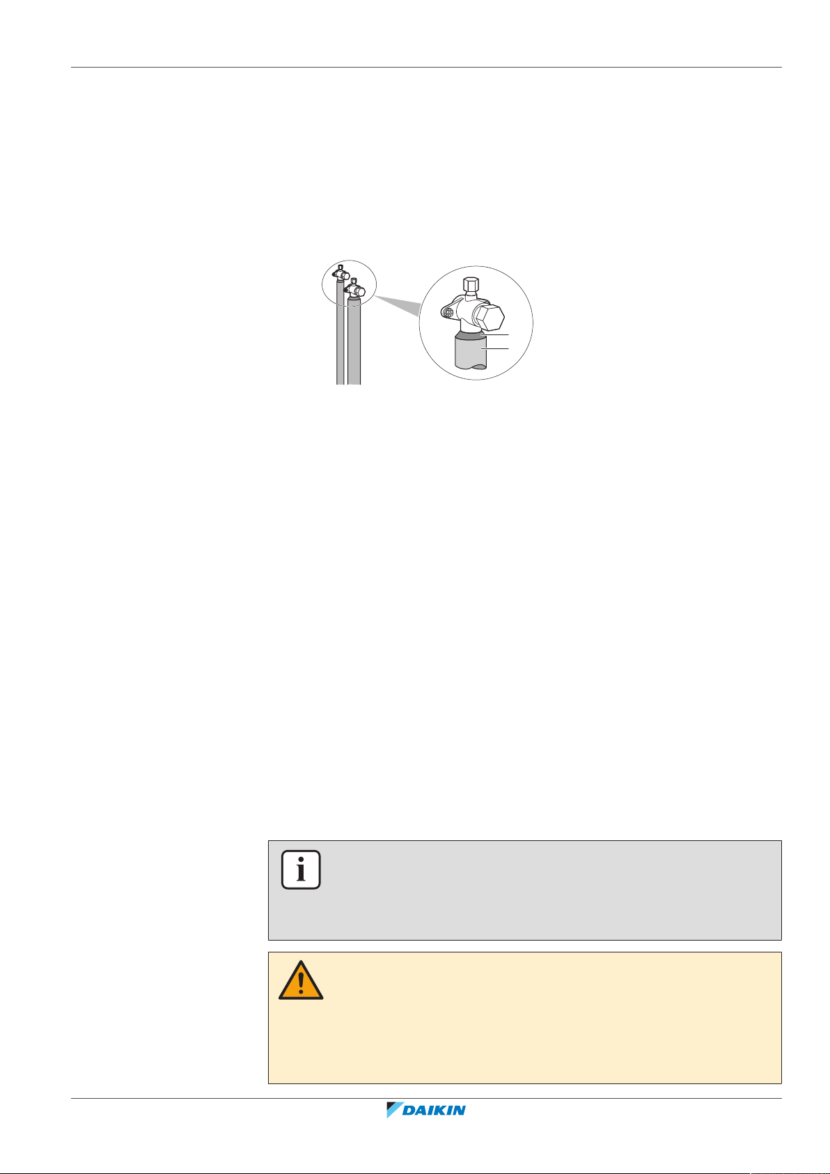
18 | Piping installation
a
b
▪ Use heat resistant polyethylene foam which can withstand a temperature of 70°C
for liquid piping and polyethylene foam which can withstand a temperature of
120°C for gas piping.
▪ Reinforce the insulation on the refrigerant piping according to the installation
environment.
▪ If there is a possibility that condensation on the stop valve might drip down into
the indoor unit through gaps in the insulation and piping because the outdoor
unit is located higher than the indoor unit, this must be prevented by sealing up
the connections. See below figure.
a Insulation material
b Caulking etc.
18.4 Charging refrigerant
18.4.1 About charging refrigerant
The outdoor unit is factory charged with refrigerant, but depending on the field
piping you have to charge additional refrigerant.
Before charging refrigerant
Make sure the outdoor unit's external refrigerant piping is checked (leak test,
vacuum drying).
Typical workflow
Charging additional refrigerant typically consists of the following stages:
1 Determining how much you have to charge additionally.
2 Charging additional refrigerant (pre-charging and/or charging).
3 Filling in the fluorinated greenhouse gases label, and fixing it to the inside of
the outdoor unit.
18.4.2 Precautions when charging refrigerant
INFORMATION
Also read the precautions and requirements in the following chapters:
▪ General safety precautions
▪ Preparation
RXYSQ4~6T8V/YB
VRV IV-S system air conditioner
4P482277-1B – 2020.10
WARNING
▪ ONLY use R410A as refrigerant. Other substances may cause explosions and
accidents.
▪ R410A contains fluorinated greenhouse gases. Its global warming potential (GWP)
value is 2087.5. Do NOT vent these gases into the atmosphere.
▪ When charging refrigerant, ALWAYS use protective gloves and safety glasses.
Installer and user reference guide
83
18 | Piping installation
NOTICE
If the power of some units is turned off, the charging procedure cannot be finished
properly.
NOTICE
Be sure to turn ON the power 6 hours before operation in order to have power
running to the crankcase heater and to protect the compressor.
NOTICE
If operation is performed within 12 minutes after the indoor and outdoor units are
powered on, the compressor will not operate before the communication is
established in a correct way between outdoor unit(s) and indoor units.
NOTICE
Before starting charging procedures, check if the 7‑LEDs display is as normal (see "To
access mode 1 or 2"[4101]), and there is no malfunction code on the user interface
of the indoor unit. If a malfunction code is present, see "24.3Solving problems based
on error codes"[4122].
NOTICE
Make sure all connected indoor units are recognised (setting [1‑5]).
NOTICE
Close the front panel before any refrigerant charge operation is executed. Without
the front panel attached the unit cannot judge correctly whether it is operating
properly or not.
NOTICE
In case of maintenance and the system (outdoor unit+field piping+indoor units) does
not contain any refrigerant any more (e.g., after refrigerant reclaim operation), the
unit has to be charged with its original amount of refrigerant (refer to the nameplate
on the unit) and the determined additional refrigerant amount.
18.4.3 To determine the additional refrigerant amount
INFORMATION
For final charge adjustment in a test laboratory, contact your dealer.
INFORMATION
Note down the amount of additional refrigerant that is calculated here, for later use
on the additional refrigerant charge label. See "To fix the fluorinated greenhouse
gases label"[487].
Installer and user reference guide
84
Formula:
R=[(X1×Ø9.5)×0.059+(X2×Ø6.4)×0.022]
R Additional refrigerant to be charged [in kg and rounded off to 1 decimal place]
X
Total length [m] of liquid piping size at Øa
1...2
Metric piping. When using metric piping, replace the weight factors in the formula
by the ones from the following table:
VRV IV-S system air conditioner
RXYSQ4~6T8V/YB
4P482277-1B – 2020.10
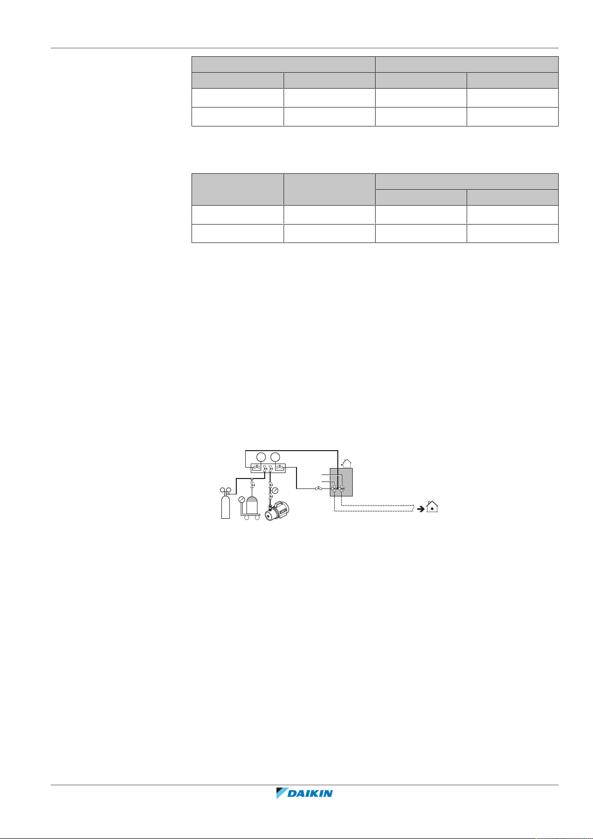
Connection ratio requirements. When selecting indoor units, the connection ratio
p<p
>
N2
C
b c e
a
g
f
d
A B
must comply with the following requirements. For more information, see the
technical engineering data.
Indoor units Total CR
(a)
(b)
18.4.4 To charge refrigerant
To speed up the refrigerant charging process, it is in case of larger systems
recommended to first pre-charge a portion of refrigerant through the liquid line
before proceeding with the manual charging. It can be skipped, but charging will
take longer then.
18 | Piping installation
Inch piping Metric piping
Piping Weight factor Piping Weight factor
Ø6.4mm 0.022 Ø6mm 0.018
Ø9.5mm 0.059 Ø10mm 0.065
(a)
CR per type
VRVDX RADX
VRVDX 50~130% 50~130% —
RADX 80~130% — 80~130%
Total CR = Total indoor unit capacity connection ratio
CR per type = Allowable capacity connection ratio per indoor unit type
(b)
Pre-charging refrigerant
Pre-charging can be done without compressor operation, by connecting the
refrigerant bottle to the service port of the liquid stop valve.
1 Connect as shown. Make sure that all outdoor unit stop valves, as well as valve
A are closed.
a Pressure reducing valve
b Nitrogen
c Weighing scales
d Refrigerant R410A tank (siphon system)
e Vacuum pump
f Liquid line stop valve
g Gas line stop valve
A Valve A
B Valve B
C Valve C
2 Open valves C and B.
3 Pre‑charge refrigerant until the determined additional refrigerant amount is
reached or pre‑charging is not possible anymore, and then close valves C and
B.
RXYSQ4~6T8V/YB
VRV IV-S system air conditioner
4P482277-1B – 2020.10
4 Do one of the following:
Installer and user reference guide
85
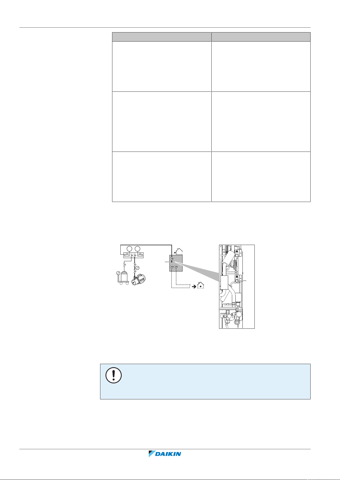
18 | Piping installation
p<p
>
R410A
a c
d
b
A
d
If Then
The determined additional refrigerant
amount is reached
Disconnect the manifold from the
liquid line.
You do not have to perform the
"Charging refrigerant (in manual
additional refrigerant charge mode)"
instructions.
Too much refrigerant is charged Recover refrigerant.
Disconnect the manifold from the
liquid line.
You do not have to perform the
"Charging refrigerant (in manual
additional refrigerant charge mode)"
instructions.
The determined additional refrigerant
amount is not reached yet
Disconnect the manifold from the
liquid line.
Continue with the "Charging
refrigerant (in manual additional
refrigerant charge mode)"
instructions.
Charging refrigerant (in manual additional refrigerant charge mode)
The remaining additional refrigerant charge can be charged by operating the
outdoor unit by means of the manual additional refrigerant charge mode.
5 Connect as shown. Make sure valve A is closed.
a Weighing scales
b Refrigerant R410A tank (siphon system)
c Vacuum pump
d Refrigerant charge port
A Valve A
NOTICE
The refrigerant charging port is connected to the piping inside the unit. The unit's
internal piping is already factory charged with refrigerant, so be careful when
connecting the charge hose.
6 Open all outdoor unit stop valves. At this point, valve A must remain closed!
7 Take all the precautions mentioned in "20 Configuration" [4 99] and
Commissioning into account.
8 Turn on the power of the indoor units and outdoor unit.
Installer and user reference guide
86
VRV IV-S system air conditioner
RXYSQ4~6T8V/YB
4P482277-1B – 2020.10
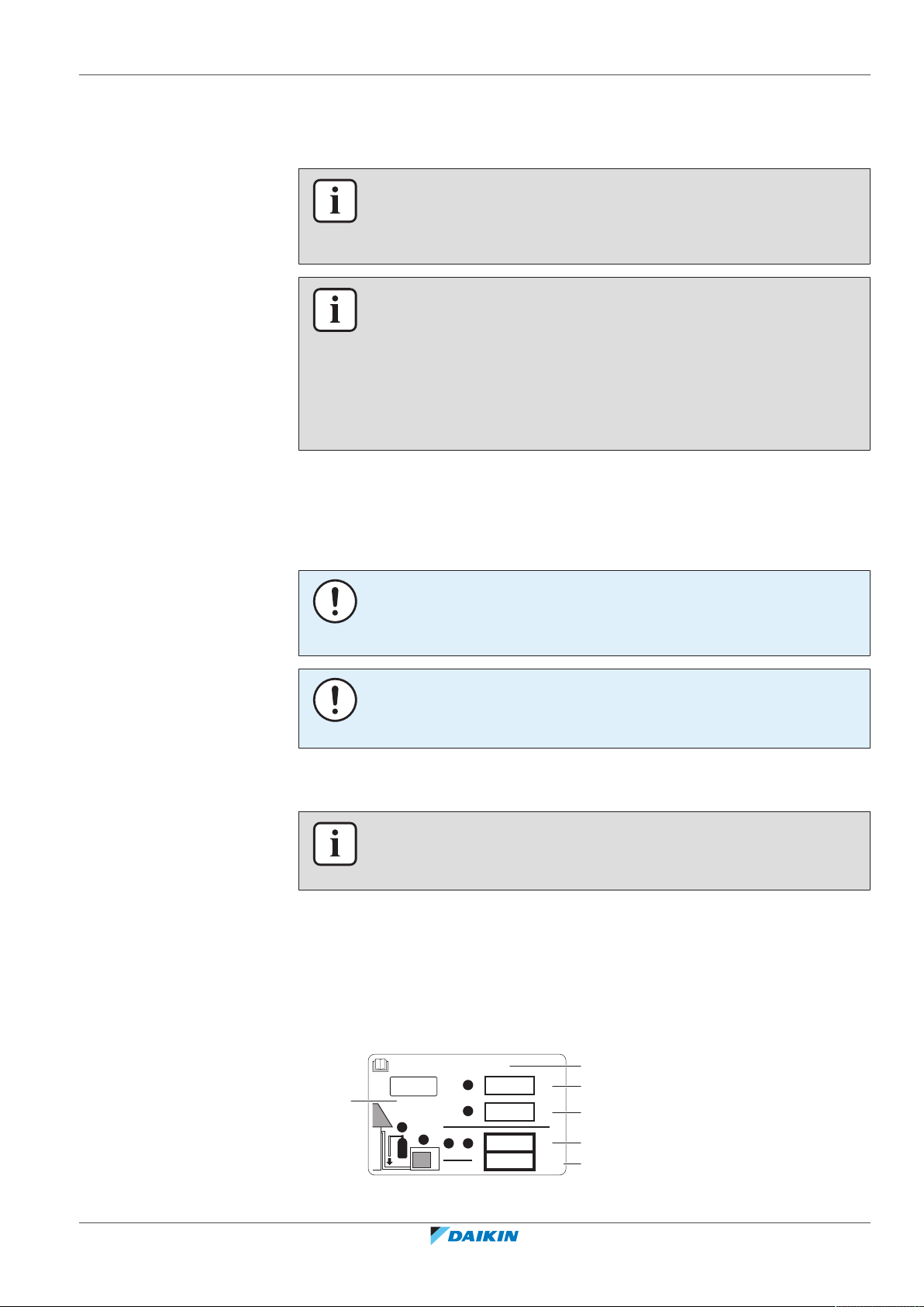
18 | Piping installation
b
Contains fluorinated greenhouse gases
2
1
1
1
2
2
kg
tCO2eq
GWP × kg
1000
=
=
+
kg
=
kg
=
GWP: XXX
RXXX
a
f
c
d
e
9 Activate setting [2‑20] to start the manual additional refrigerant charge mode.
For details, see Mode 2: Field settings.
Result: The unit will start operation.
INFORMATION
The manual refrigerant charge operation will automatically stop within 30 minutes. If
charging is not completed after 30 minutes, perform the additional refrigerant
charging operation again.
INFORMATION
▪ When a malfunction is detected during the procedure (e.g., in case of closed stop
valve), a malfunction code will be displayed. In that case, refer to "Error codes
when charging refrigerant" [4 87] and solve the malfunction accordingly.
Resetting the malfunction can be done by pushing BS3. You can restart the
"Charging" instructions.
▪ Aborting the manual refrigerant charge is possible by pushing BS3. The unit will
stop and return to idle condition.
10 Open valve A.
11 Charge refrigerant until the remaining determined additional refrigerant
amount is added, and then close valve A.
12 Press BS3 to stop the manual additional refrigerant charge mode.
NOTICE
Make sure to open all stop valves after (pre-) charging the refrigerant.
Operating with the stop valves closed will damage the compressor.
NOTICE
After adding the refrigerant, do not forget to close the lid of the refrigerant charging
port. The tightening torque for the lid is 11.5 to 13.9N•m.
18.4.5 Error codes when charging refrigerant
INFORMATION
If a malfunction occurs, the error code is displayed on the user interface of the
indoor unit.
If a malfunction occurs, close valve A immediately. Confirm the malfunction code
and take corresponding action, "24.3 Solving problems based on error
codes"[4122].
18.4.6 To fix the fluorinated greenhouse gases label
1 Fill in the label as follows:
RXYSQ4~6T8V/YB
VRV IV-S system air conditioner
4P482277-1B – 2020.10
Installer and user reference guide
87

18 | Piping installation
a If a multilingual fluorinated greenhouse gases label is delivered with the unit (see
accessories), peel off the applicable language and stick it on top of a.
b Factory refrigerant charge: see unit name plate
c Additional refrigerant amount charged
d Total refrigerant charge
e Quantity of fluorinated greenhouse gases of the total refrigerant charge
expressed as tonnes CO2 equivalent.
f GWP = Global warming potential
NOTICE
Applicable legislation on fluorinated greenhouse gases requires that the refrigerant
charge of the unit is indicated both in weight and CO2 equivalent.
Formula to calculate the quantity in CO2 equivalent tonnes: GWP value of the
refrigerant × total refrigerant charge [in kg] / 1000
Use the GWP value mentioned on the refrigerant charge label.
2 Fix the label on the inside of the outdoor unit near the gas and liquid stop
valves.
Installer and user reference guide
88
VRV IV-S system air conditioner
RXYSQ4~6T8V/YB
4P482277-1B – 2020.10

19 Electrical installation
In this chapter
19.1 About connecting the electrical wiring .................................................................................................................................. 89
19.1.1 Precautions when connecting the electrical wiring .............................................................................................. 89
19.1.2 Field wiring: Overview............................................................................................................................................ 91
19.1.3 Guidelines when knocking out knockout holes..................................................................................................... 92
19.1.4 Guidelines when connecting the electrical wiring ................................................................................................ 92
19.1.5 About electrical compliance .................................................................................................................................. 93
19.1.6 Safety device requirements................................................................................................................................... 93
19.2 To connect the electrical wiring to the outdoor unit ............................................................................................................ 94
19.3 To finish the transmission wiring ........................................................................................................................................... 97
19.4 To check the insulation resistance of the compressor .......................................................................................................... 98
19.1 About connecting the electrical wiring
Typical workflow
Connecting the electrical wiring typically consists of the following stages:
1 Making sure the power supply system complies with the electrical
specifications of the units.
2 Connecting the electrical wiring to the outdoor unit.
3 Connecting the electrical wiring to the indoor units.
4 Connecting the main power supply.
19 | Electrical installation
19.1.1 Precautions when connecting the electrical wiring
INFORMATION
Also read the precautions and requirements in the following chapters:
▪ General safety precautions
▪ Preparation
DANGER: RISK OF ELECTROCUTION
WARNING
ALWAYS use multicore cable for power supply cables.
INFORMATION
Also read the precautions and requirements in the "2 General safety
precautions"[48].
WARNING
▪ All wiring MUST be performed by an authorised electrician and MUST comply
with the applicable legislation.
▪ Make electrical connections to the fixed wiring.
▪ All components procured on-site and all electrical construction MUST comply
with the applicable legislation.
RXYSQ4~6T8V/YB
VRV IV-S system air conditioner
4P482277-1B – 2020.10
Installer and user reference guide
89

19 | Electrical installation
WARNING
▪ If the power supply has a missing or wrong N-phase, equipment might break
down.
▪ Establish proper earthing. Do NOT earth the unit to a utility pipe, surge absorber,
or telephone earth. Incomplete earthing may cause electrical shock.
▪ Install the required fuses or circuit breakers.
▪ Secure the electrical wiring with cable ties so that the cables do NOT come in
contact with sharp edges or piping, particularly on the high-pressure side.
▪ Do NOT use taped wires, stranded conductor wires, extension cords, or
connections from a star system. They can cause overheating, electrical shock or
fire.
▪ Do NOT install a phase advancing capacitor, because this unit is equipped with an
inverter. A phase advancing capacitor will reduce performance and may cause
accidents.
CAUTION
Do NOT push or place redundant cable length in the unit.
NOTICE
The distance between the high voltage and low voltage cables should be at least
50mm.
NOTICE
Do NOT operate the unit until the refrigerant piping is complete. Running the unit
before the piping is ready will break the compressor.
NOTICE
If the power supply has a missing or wrong N-phase, equipment will break down.
NOTICE
Do NOT install a phase advancing capacitor, because this unit is equipped with an
inverter. A phase advancing capacitor will reduce performance and may cause
accidents.
NOTICE
NEVER remove a thermistor, sensor, etc., when connecting power wiring and
transmission wiring. (If operated without thermistor, sensor, etc., the compressor
may break down.)
NOTICE
▪ The reversed phase protection detector of this product only functions when the
product starts up. Consequently reversed phase detection is not performed
during normal operation of the product.
▪ The reversed phase protection detector is designed to stop the product in the
event of an abnormality when the product is started up.
▪ Replace 2 of the 3 phases (L1, L2, and L3) during reverse-phase protection
abnormality.
Installer and user reference guide
90
VRV IV-S system air conditioner
RXYSQ4~6T8V/YB
4P482277-1B – 2020.10

19.1.2 Field wiring: Overview
A
B
C
b2
b3
c1
c2
b1
a
Field wiring consists of:
▪ power supply (including earth),
▪ DIII transmission wiring between communication box and outdoor unit,
▪ RS‑485 transmission wiring between communication box and monitoring system.
Transmission wiring
The transmission wiring outside the unit should be wrapped and routed together
with the field piping. See Finishing the outdoor unit installation.
19 | Electrical installation
NOTICE
▪ Be sure to keep the power line and transmission line apart from each other.
Transmission wiring and power supply wiring may cross, but may NOT run
parallel.
▪ In order to avoid any electrical interference the distance between both wirings
should ALWAYS be at least 50mm.
Transmission wiring specification and limits
Vinyl cords with 0.75 to 1.25mm² sheath or cables (2‑core wires)
(a)
Maximum number of branches for unit-to-unit cabling 9
Maximum wiring length
300m
(distance between outdoor and furthest indoor unit)
Total wiring length
600m
(sum of distances between outdoor and all indoor units)
(a)
If the total transmission wiring exceeds these limits, communication errors might occur.
No secondary branchings are allowed after any transmission wire branching.
A Outdoor unit
RXYSQ4~6T8V/YB
VRV IV-S system air conditioner
4P482277-1B – 2020.10
b1, b2, b3 Branch lines
Example:
B Indoor unit
C Central user interface (etc...)
a Main line
c1, c2 No branch is allowed after branch
Installer and user reference guide
91

19 | Electrical installation
e
d
F1/F2
(16 V)
F1/F2
(16 V)
220-240 V
1~ 50 Hz
c
a
Y
V
b
220-240 V
1~ 50 Hz
380-415 V
3N~ 50 Hz
b
c
a
b a
19.1.3 Guidelines when knocking out knockout holes
a Main switch
b Earth connection
c Power supply wiring (including earth) (shielded cable)
F1/F2 Transmission wiring (shielded cable)
V Outdoor unit (RXYSQ4~6_V)
Y Outdoor unit (RXYSQ4~6_Y)
d Indoor unit
e User interface
NOTICE
Precautions when making knockout holes:
▪ Avoid damaging the casing.
▪ After making the knockout holes, we recommend you remove the burrs and paint
the edges and areas around the edges using repair paint to prevent rusting.
▪ When passing electrical wiring through the knockout holes, wrap the wiring with
protective tape to prevent damage.
a Knockout hole
b Burr
c Sealant etc.
19.1.4 Guidelines when connecting the electrical wiring
Keep the following in mind:
▪ If stranded conductor wires are used, install a round crimp-style terminal on the
end of the wire. Place the round crimp-style terminal on the wire up to the
covered part and fasten the terminal with the appropriate tool.
Installer and user reference guide
92
a Stranded conductor wire
b Round crimp-style terminal
▪ Use the following methods for installing wires:
VRV IV-S system air conditioner
RXYSQ4~6T8V/YB
4P482277-1B – 2020.10

Wire type Installation method
c b
c
aa
A
AA´
A´
c b ba c
a
B
B
Single-core wire
Stranded conductor wire
with round crimp-style
terminal
19 | Electrical installation
a Curled single-core wire
b Screw
c Flat washer
a Terminal
b Screw
c Flat washer
Tightening torques
Wiring Screw size Tightening torque
Power supply wiring
(power supply +
shielded ground)
Transmission wiring M3.5 0.8~0.97
19.1.5 About electrical compliance
Only for RXYSQ4~6_V
Equipment complying with EN/IEC 61000‑3‑12 (European/International Technical
Standard setting the limits for harmonic currents produced by equipment
connected to public low-voltage systems with input current >16 A and ≤75 A per
phase.).
19.1.6 Safety device requirements
Allowed
NOT allowed
(N•m)
M5 2.2~2.7
RXYSQ4~6T8V/YB
VRV IV-S system air conditioner
4P482277-1B – 2020.10
Power supply wiring
The power supply must be protected with the required safety devices, i.e. a main
switch, a slow blow fuse on each phase and an earth leakage protector in
accordance with the applicable legislation.
Selection and sizing of the wiring should be done in accordance with the applicable
legislation based on the information mentioned in the table below.
Installer and user reference guide
93

19 | Electrical installation
a b
Model Minimum circuit
ampacity
Recommended
fuses
Power supply
RXYSQ4_V 29.1A 32A 1~ 50Hz
RXYSQ5_V
220-240V
RXYSQ6_V
RXYSQ4_Y 14.1A 16A 3N~ 50Hz
RXYSQ5_Y
380-415V
RXYSQ6_Y
Transmission wiring
Transmission wiring specification and limits
(a)
Vinyl cords with 0.75 to 1.25mm² sheath or cables (2‑core wires)
Maximum number of branches for unit-to-unit cabling 9
Maximum wiring length
300m
(distance between outdoor and furthest indoor unit)
Total wiring length
600m
(sum of distances between outdoor and all indoor units)
(a)
If the total transmission wiring exceeds these limits, communication errors might occur.
19.2 To connect the electrical wiring to the outdoor unit
NOTICE
▪ Follow the wiring diagram (delivered with the unit, located at the inside of the
service cover).
▪ Make sure the electrical wiring does NOT obstruct proper reattachment of the
service cover.
1 Remove the service cover. See "To open the outdoor unit"[462].
2 Strip insulation (20mm) from the wires.
a Strip wire end to this point
b An excessive strip length may cause electrical shock or leakage
3 Connect the transmission wiring as follows:
Installer and user reference guide
94
VRV IV-S system air conditioner
RXYSQ4~6T8V/YB
4P482277-1B – 2020.10

19 | Electrical installation
F1 F2 F1 F2 F1 F2
F1 F2 F1 F2 F1 F2
a
b
X2M
TO OUT/DTO IN/D
C/H SELECTOR
A B C F1 F2 F1 F2
TO IN/D
UNIT
V Y
F1 F2 F1 F2
TO IND TO OUTD
TO OUT/D
UNIT
aa
1~ 50 Hz
220-240 V
LLN
V Y
X1M
3N~ 50 Hz
380-415 V
L1 L2 L3
L1 L2 L3
N
X1M
a
b
c
a Use the conductor of sheathed wire (2 wire) (no polarity)
b Terminal board (field supply)
NOTICE
You must use shielded wire and connect the earth to the transmission terminal
(X2M).
a Earth
4 Connect the power supply as follows:
a Earth leakage circuit breaker
b Fuse
c Power supply cable
5 Fix the cables (power supply and transmission wiring) with cable ties.
RXYSQ4~6T8V/YB
VRV IV-S system air conditioner
4P482277-1B – 2020.10
Installer and user reference guide
95
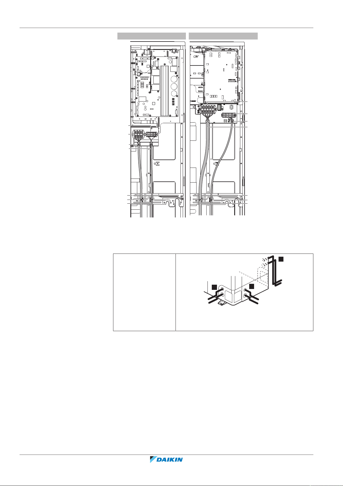
19 | Electrical installation
V
Y
X1M
X2M
a
a
b
a
a
X2M
a
a
b
X1M
a
a
a
b
a
b
a
b
2
3
1
a Cable tie
b Attachment plate
X1M Power supply
X2M Transmission wiring
6 Route the wiring through the frame and connect it to it.
Routing through the
frame
a Power supply cable
b Transmission wiring cable
Installer and user reference guide
96
VRV IV-S system air conditioner
RXYSQ4~6T8V/YB
4P482277-1B – 2020.10
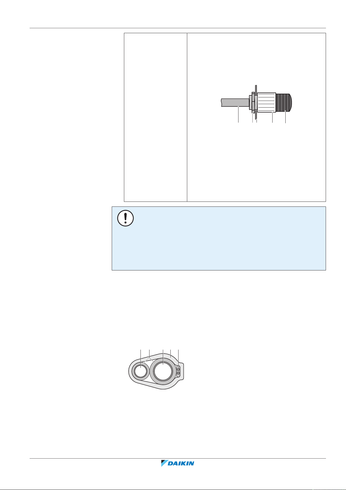
19 | Electrical installation
a b
A B
c d e
a bc de
Connecting to the
frame
When cables are routed from the unit, a protection
sleeve for the conduits (PG insertions) can be
inserted at the knockout hole.
When you do not use a wire conduit, protect the
wires with vinyl tubes to prevent the edge of the
knockout hole from cutting the wires.
A Inside of the outdoor unit
B Outside of the outdoor unit
a Wire
b Bush
c Nut
d Frame
e Hose
NOTICE
Precautions when making knockout holes:
▪ Avoid damaging the casing and underlying piping.
▪ After making the knockout holes, we recommend to remove the burrs and paint
the edges and areas around the edges using repair paint to prevent rusting.
▪ When passing electrical wiring through the knockout holes, wrap the wiring with
protective tape to prevent damage.
7 Reattach the service cover. See "To close the outdoor unit"[462].
8 Connect an earth leakage circuit breaker and fuse to the power supply line.
19.3 To finish the transmission wiring
After installing the transmission wires inside the unit, wrap them along with the onsite refrigerant pipes using finishing tape, as shown in figure below.
RXYSQ4~6T8V/YB
VRV IV-S system air conditioner
4P482277-1B – 2020.10
a Liquid pipe
b Gas pipe
c Insulator
d Transmission wiring (F1/F2)
e Finishing tape
Installer and user reference guide
97
19 | Electrical installation
19.4 To check the insulation resistance of the compressor
NOTICE
If, after installation, refrigerant accumulates in the compressor, the insulation
resistance over the poles can drop, but if it is at least 1 MΩ, then the unit will not
break down.
▪ Use a 500V mega-tester when measuring insulation.
▪ Do NOT use a mega-tester for low voltage circuits.
1 Measure the insulation resistance over the poles.
If Then
≥1MΩ Insulation resistance is OK. This procedure is
finished.
<1MΩ Insulation resistance is not OK. Go to the next step.
2 Turn ON the power and leave it on for 6hours.
Result: The compressor will heat up and evaporate any refrigerant in the
compressor.
3 Measure the insulation resistance again.
Installer and user reference guide
98
VRV IV-S system air conditioner
RXYSQ4~6T8V/YB
4P482277-1B – 2020.10
20 Configuration
In this chapter
20.1 Overview: Configuration......................................................................................................................................................... 99
20.2 Making field settings............................................................................................................................................................... 99
20.2.1 About making field settings ................................................................................................................................... 99
20.2.2 To access the field setting components ................................................................................................................ 100
20.2.3 Field setting components....................................................................................................................................... 100
20.2.4 To access mode 1 or 2............................................................................................................................................ 101
20.2.5 To use mode 1........................................................................................................................................................ 102
20.2.6 To use mode 2........................................................................................................................................................ 103
20.2.7 Mode 1: Monitoring settings................................................................................................................................. 104
20.2.8 Mode 2: Field settings............................................................................................................................................ 104
20.2.9 To connect the PC configurator to the outdoor unit ............................................................................................ 107
20.3 Energy saving and optimum operation .................................................................................................................................. 108
20.3.1 Available main operation methods........................................................................................................................ 108
20.3.2 Available comfort settings ..................................................................................................................................... 109
20.3.3 Example: Automatic mode during cooling ............................................................................................................ 111
20.3.4 Example: Automatic mode during heating............................................................................................................ 112
20.1 Overview: Configuration
20 | Configuration
This chapter describes what you have to do and know to configure the system after
it is installed.
It contains information about:
▪ Making field settings
▪ Energy saving and optimum operation
INFORMATION
It is important that all information in this chapter is read sequentially by the installer
and that the system is configured as applicable.
DANGER: RISK OF ELECTROCUTION
20.2 Making field settings
20.2.1 About making field settings
To configure the heat pump system, you must give input to the outdoor unit's main
PCB (A1P). This involves the following field setting components:
RXYSQ4~6T8V/YB
VRV IV-S system air conditioner
4P482277-1B – 2020.10
▪ Push buttons to give input to the PCB
▪ A display to read feedback from the PCB
▪ DIP switches (only change the factory settings if you install a cool/heat selector
switch).
Field settings are defined by their mode, setting and value. Example: [2‑8]=4.
Installer and user reference guide
99
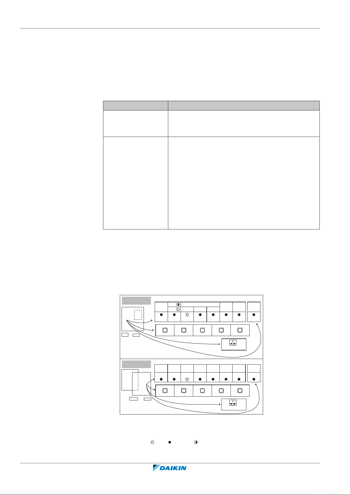
20 | Configuration
V
Y
H1P H2P H3P H4P H5P H6P H7P
MODE
TEST:
L.N.O.P.
DEMAND
C/H SELECT
HWL:
IND
MASTER
SLAVE
H8P
MULTI
BS2
SET
BS1
MODE
BS3
RETURN
BS2
SET
BS1
MODE
BS3
RETURN
BS4
TEST
BS5
RESET
BS4
TEST
BS5
RESET
H1P H2P H3P H4P H5P H6P H7P H8P
X1M
X2M
A1P
A2P
A1P
A2P
X1M
X2M
1 2
OFF
ON
DS1
1 2
OFF
ON
DS1
MULTIDEMANDL.N.O.P.SLAVEMASTERIND
TEST/
HWL
MODE
PC configurator
For VRV IV-S heat pump system it is alternatively possible to make several
commissioning field settings through a personal computer interface (for this,
option EKPCCAB* is required). The installer can prepare the configuration (off-site)
on PC and afterwards upload the configuration to the system.
See also: "To connect the PC configurator to the outdoor unit"[4107].
Mode 1 and 2
Mode Description
Mode 1
(monitoring settings)
Mode 2
(field settings)
20.2.2 To access the field setting components
See "To open the outdoor unit"[462].
20.2.3 Field setting components
Mode1 can be used to monitor the current situation of
the outdoor unit. Some field setting contents can be
monitored as well.
Mode2 is used to change the field settings of the
system. Consulting the current field setting value and
changing the current field setting value is possible.
In general, normal operation can be resumed without
special intervention after changing field settings.
Some field settings are used for special operation (e.g., 1
time operation, recovery/vacuuming setting, manual
adding refrigerant setting, etc.). In such a case, it is
required to abort the special operation before normal
operation can restart. It will be indicated in below
explanations.
The components to make field settings are as follows:
DS1 DIP switches
BS1~BS5 Push buttons
H1P~H7P 7‑LEDs display
H8P LED for indication during initialisation
ON ( ) OFF ( ) Flashing ( )
Installer and user reference guide
100
VRV IV-S system air conditioner
RXYSQ4~6T8V/YB
4P482277-1B – 2020.10
 Loading...