

Daikin RXYQQ8U7Y1B*, RXYQQ10U7Y1B*, RXYQQ12U7Y1B*, RXYQQ14U7Y1B*, RXYQQ16U7Y1B* Installer reference guide
...
Installer and user reference guide
VRV IV Q+ series heat pump
RXYQQ8U7Y1B*
RXYQQ10U7Y1B*
RXYQQ12U7Y1B*
RXYQQ14U7Y1B*
RXYQQ16U7Y1B*
RXYQQ18U7Y1B*
RXYQQ20U7Y1B*

Table of contents
Table of contents
1 About the documentation 6
1.1 About this document ...................................................................................................................................................... 6
1.2 Meaning of warnings and symbols................................................................................................................................. 7
2 General safety precautions 9
2.1 For the installer............................................................................................................................................................... 9
2.1.1 General ........................................................................................................................................................... 9
2.1.2 Installation site ............................................................................................................................................... 10
2.1.3 Refrigerant — in case of R410A or R32.......................................................................................................... 10
2.1.4 Electrical ......................................................................................................................................................... 12
3 Specific installer safety instructions 15
For the user 18
4 User safety instructions 19
4.1 General............................................................................................................................................................................ 19
4.2 Instructions for safe operation ....................................................................................................................................... 20
5 About the system 23
5.1 System layout.................................................................................................................................................................. 23
6 User interface 24
7 Before operation 25
8 Operation 27
8.1 Operation range.............................................................................................................................................................. 27
8.2 Operating the system ..................................................................................................................................................... 27
8.2.1 About operating the system........................................................................................................................... 27
8.2.2 About cooling, heating, fan only, and automatic operation ......................................................................... 28
8.2.3 About the heating operation.......................................................................................................................... 28
8.2.4 To operate the system (WITHOUT cool/heat changeover remote control switch)...................................... 29
8.2.5 To operate the system (WITH cool/heat changeover remote control switch) ............................................. 29
8.3 Using the dry program.................................................................................................................................................... 30
8.3.1 About the dry program................................................................................................................................... 30
8.3.2 To use the dry program (WITHOUT cool/heat changeover remote control switch) .................................... 30
8.3.3 To use the dry program (WITH cool/heat changeover remote control switch) ........................................... 30
8.4 Adjusting the air flow direction ...................................................................................................................................... 31
8.4.1 About the air flow flap.................................................................................................................................... 31
8.5 Setting the master user interface................................................................................................................................... 32
8.5.1 About setting the master user interface........................................................................................................ 32
8.5.2 To designate the master user interface (VRV DX and Hydrobox) ................................................................. 33
8.6 About control systems .................................................................................................................................................... 33
9 Energy saving and optimum operation 34
9.1 Available main operation methods ................................................................................................................................ 34
9.2 Available comfort settings .............................................................................................................................................. 35
10 Maintenance and service 36
10.1 Maintenance after a long stop period............................................................................................................................ 36
10.2 Maintenance before a long stop period......................................................................................................................... 37
10.3 About the refrigerant...................................................................................................................................................... 37
10.4 After-sales service and warranty .................................................................................................................................... 37
10.4.1 Warranty period............................................................................................................................................. 37
10.4.2 Recommended maintenance and inspection................................................................................................ 38
10.4.3 Recommended maintenance and inspection cycles ..................................................................................... 38
10.4.4 Shortened maintenance and replacement cycles......................................................................................... 39
Installer and user reference guide
2
11 Troubleshooting 40
11.1 Error codes: Overview .................................................................................................................................................... 41
11.2 Symptoms that are NOT system malfunctions............................................................................................................... 44
11.2.1 Symptom: The system does not operate....................................................................................................... 44
11.2.2 Symptom: Cool/Heat cannot be changed over ............................................................................................. 44
11.2.3 Symptom: Fan operation is possible, but cooling and heating do not work ................................................ 44
11.2.4 Symptom: The fan speed does not correspond to the setting...................................................................... 44
RXYQQ8~20U7Y1B
VRV IV Q+ series heat pump
4P546229-1A – 2020.10

Table of contents
11.2.5 Symptom: The fan direction does not correspond to the setting................................................................. 44
11.2.6 Symptom: White mist comes out of a unit (Indoor unit) .............................................................................. 45
11.2.7 Symptom: White mist comes out of a unit (Indoor unit, outdoor unit)........................................................ 45
11.2.8 Symptom: The user interface reads "U4" or "U5" and stops, but then restarts after a few minutes.......... 45
11.2.9 Symptom: Noise of air conditioners (Indoor unit)......................................................................................... 45
11.2.10 Symptom: Noise of air conditioners (Indoor unit, outdoor unit) .................................................................. 45
11.2.11 Symptom: Noise of air conditioners (Outdoor unit)...................................................................................... 45
11.2.12 Symptom: Dust comes out of the unit........................................................................................................... 46
11.2.13 Symptom: The units can give off odours ....................................................................................................... 46
11.2.14 Symptom: The outdoor unit fan does not spin.............................................................................................. 46
11.2.15 Symptom: The display shows "88"................................................................................................................. 46
11.2.16 Symptom: The compressor in the outdoor unit does not stop after a short heating operation ................. 46
11.2.17 Symptom: The inside of an outdoor unit is warm even when the unit has stopped.................................... 46
11.2.18 Symptom: Hot air can be felt when the indoor unit is stopped.................................................................... 46
12 Relocation 47
13 Disposal 48
14 Technical data 49
14.1 Information requirements for Eco Design...................................................................................................................... 49
For the installer 50
15 About the box 51
15.1 About LOOP BY DAIKIN ................................................................................................................................................... 51
15.2 Overview: About the box ................................................................................................................................................ 51
15.3 To unpack the outdoor unit ............................................................................................................................................ 52
15.4 To remove the accessories from the outdoor unit ........................................................................................................ 53
15.5 Accessory pipes: Diameters ............................................................................................................................................ 53
15.6 To remove the transportation stay ................................................................................................................................ 54
16 About the units and options 55
16.1 Overview: About the units and options.......................................................................................................................... 55
16.2 Identification label: Outdoor unit ................................................................................................................................... 55
16.3 About the outdoor unit................................................................................................................................................... 56
16.4 System layout .................................................................................................................................................................. 56
16.5 Combining units and options .......................................................................................................................................... 57
16.5.1 About combining units and options............................................................................................................... 57
16.5.2 Possible combinations of indoor units........................................................................................................... 57
16.5.3 Possible combinations of outdoor units ........................................................................................................ 58
16.5.4 Possible options for the outdoor unit............................................................................................................ 59
17 Unit installation 61
17.1 Preparing the installation site......................................................................................................................................... 61
17.1.1 Installation site requirements of the outdoor unit........................................................................................ 61
17.1.2 Additional installation site requirements of the outdoor unit in cold climates............................................ 63
17.1.3 Securing safety against refrigerant leaks....................................................................................................... 64
17.2 Opening the unit ............................................................................................................................................................. 66
17.2.1 About opening the units................................................................................................................................. 66
17.2.2 To open the outdoor unit............................................................................................................................... 66
17.2.3 To open the electrical component box of the outdoor unit ......................................................................... 67
17.3 Mounting the outdoor unit............................................................................................................................................. 68
17.3.1 To provide the installation structure ............................................................................................................. 68
18 Piping installation 70
18.1 Preparing refrigerant piping ........................................................................................................................................... 70
18.1.1 Refrigerant piping requirements.................................................................................................................... 70
18.1.2 Refrigerant piping insulation.......................................................................................................................... 71
18.1.3 To select the piping size ................................................................................................................................. 72
18.1.4 To select refrigerant branch kits.................................................................................................................... 74
18.1.5 About the piping length.................................................................................................................................. 75
18.1.6 Piping length: VRV DX only............................................................................................................................. 76
18.1.7 Multiple outdoor units: Possible layouts....................................................................................................... 79
18.2 Connecting the refrigerant piping .................................................................................................................................. 80
18.2.1 About connecting the refrigerant piping....................................................................................................... 80
18.2.2 Precautions when connecting the refrigerant piping.................................................................................... 81
18.2.3 Multiple outdoor units: Knockout holes........................................................................................................ 81
18.2.4 To route the refrigerant piping...................................................................................................................... 82
18.2.5 To connect the refrigerant piping to the outdoor unit ................................................................................. 82
RXYQQ8~20U7Y1B
VRV IV Q+ series heat pump
4P546229-1A – 2020.10
Installer and user reference guide
3

Table of contents
18.2.6 To connect the multi connection piping kit................................................................................................... 83
18.2.7 To connect the refrigerant branching kit....................................................................................................... 83
18.2.8 To protect against contamination.................................................................................................................. 84
18.2.9 To braze the pipe end..................................................................................................................................... 85
18.2.10 Using the stop valve and service port ............................................................................................................ 85
18.2.11 To remove the spun pipes.............................................................................................................................. 88
18.3 Checking the refrigerant piping ...................................................................................................................................... 89
18.3.1 About checking the refrigerant piping........................................................................................................... 89
18.3.2 Checking refrigerant piping: General guidelines ........................................................................................... 90
18.3.3 Checking refrigerant piping: Setup ................................................................................................................ 91
18.3.4 To perform a leak test.................................................................................................................................... 91
18.3.5 To perform vacuum drying............................................................................................................................. 92
18.3.6 To insulate the refrigerant piping .................................................................................................................. 93
18.4 Charging refrigerant........................................................................................................................................................ 93
18.4.1 Precautions when charging refrigerant ......................................................................................................... 93
18.4.2 About charging refrigerant............................................................................................................................. 94
18.4.3 To determine the additional refrigerant amount.......................................................................................... 95
18.4.4 To charge refrigerant: Flow chart .................................................................................................................. 98
18.4.5 To charge refrigerant...................................................................................................................................... 99
18.4.6 Step 6a: To automatically charge refrigerant................................................................................................ 101
18.4.7 Step 6b: To manually charge refrigerant....................................................................................................... 103
18.4.8 Error codes when charging refrigerant.......................................................................................................... 104
18.4.9 Checks after charging refrigerant .................................................................................................................. 104
18.4.10 To fix the fluorinated greenhouse gases label............................................................................................... 104
19 Electrical installation 106
19.1 About connecting the electrical wiring .......................................................................................................................... 106
19.1.1 Precautions when connecting the electrical wiring....................................................................................... 106
19.1.2 Field wiring: Overview.................................................................................................................................... 108
19.1.3 About the electrical wiring............................................................................................................................. 108
19.1.4 Guidelines when knocking out knockout holes............................................................................................. 110
19.1.5 About electrical compliance........................................................................................................................... 110
19.1.6 Safety device requirements ........................................................................................................................... 111
19.2 To route and fix the transmission wiring........................................................................................................................ 112
19.3 To connect the transmission wiring ............................................................................................................................... 114
19.4 To finish the transmission wiring.................................................................................................................................... 115
19.5 To route and fix the power supply ................................................................................................................................. 116
19.6 To connect the power supply ......................................................................................................................................... 116
19.7 To check the insulation resistance of the compressor .................................................................................................. 118
20 Configuration 119
20.1 Overview: Configuration ................................................................................................................................................. 119
20.2 Making field settings ....................................................................................................................................................... 119
20.2.1 About making field settings............................................................................................................................ 119
20.2.2 Field setting components............................................................................................................................... 121
20.2.3 To access the field setting components......................................................................................................... 121
20.2.4 To access mode 1 or 2.................................................................................................................................... 122
20.2.5 To use mode 1................................................................................................................................................ 123
20.2.6 To use mode 2................................................................................................................................................ 123
20.2.7 Mode 1: Monitoring settings ......................................................................................................................... 124
20.2.8 Mode 2: Field settings.................................................................................................................................... 126
20.2.9 To connect the PC configurator to the outdoor unit..................................................................................... 131
20.3 Energy saving and optimum operation .......................................................................................................................... 131
20.3.1 Available main operation methods................................................................................................................ 132
20.3.2 Available comfort settings.............................................................................................................................. 133
20.3.3 Example: Automatic mode during cooling..................................................................................................... 135
20.3.4 Example: Automatic mode during heating.................................................................................................... 136
21 Commissioning 138
21.1 Overview: Commissioning .............................................................................................................................................. 138
21.2 Precautions when commissioning .................................................................................................................................. 138
21.3 Checklist before commissioning ..................................................................................................................................... 139
21.4 About the test run........................................................................................................................................................... 140
21.5 To perform a test run...................................................................................................................................................... 141
21.6 Correcting after abnormal completion of the test run .................................................................................................. 142
21.7 Operating the unit........................................................................................................................................................... 142
22 Hand-over to the user 143
Installer and user reference guide
4
23 Maintenance and service 144
23.1 Maintenance safety precautions .................................................................................................................................... 144
RXYQQ8~20U7Y1B
VRV IV Q+ series heat pump
4P546229-1A – 2020.10

Table of contents
23.1.1 To prevent electrical hazards......................................................................................................................... 144
23.2 About service mode operation ....................................................................................................................................... 145
23.2.1 To use vacuum mode ..................................................................................................................................... 145
23.2.2 To recover refrigerant.................................................................................................................................... 145
24 Troubleshooting 147
24.1 Solving problems based on error codes ......................................................................................................................... 147
24.2 Error codes: Overview .................................................................................................................................................... 147
25 Disposal 153
26 Technical data 154
26.1 Service space: Outdoor unit ........................................................................................................................................... 154
26.2 Piping diagram: Outdoor unit ......................................................................................................................................... 156
26.3 Wiring diagram: Outdoor unit ........................................................................................................................................ 157
27 Glossary 162
RXYQQ8~20U7Y1B
VRV IV Q+ series heat pump
4P546229-1A – 2020.10
Installer and user reference guide
5
1 | About the documentation
1 About the documentation
In this chapter
1.1 About this document.............................................................................................................................................................. 6
1.2 Meaning of warnings and symbols......................................................................................................................................... 7
1.1 About this document
Target audience
Authorised installers + end users
Documentation set
This document is part of a documentation set. The complete set consists of:
INFORMATION
This appliance is intended to be used by expert or trained users in shops, in light
industry and on farms, or for commercial use by lay persons.
▪ General safety precautions:
- Safety instructions that you must read before installing
- Format: Paper (in the box of the outdoor unit)
▪ Outdoor unit installation and operation manual:
- Installation and operation instructions
- Format: Paper (in the box of the outdoor unit)
▪ Installer and user reference guide:
- Preparation of the installation, reference data,…
- Detailed step-by-step instructions and background information for basic and
advanced usage
- Format: Digital files on http://www.daikineurope.com/support-and-manuals/
product-information/
Latest revisions of the supplied documentation may be available on the regional
Daikin website or via your dealer.
The original documentation is written in English. All other languages are
translations.
Technical engineering data
▪ A subset of the latest technical data is available on the regional Daikin website
(publicly accessible).
Installer and user reference guide
6
▪ The full set of latest technical data is available on the Daikin Business Portal
(authentication required).
Scope of the manual
This manual describes the procedures for handling, installing and connecting the
VRV IV replacement heat pump outdoor units. This manual has been prepared to
ensure adequate maintenance of the unit, and it will provide help in case problems
occur.
RXYQQ8~20U7Y1B
VRV IV Q+ series heat pump
4P546229-1A – 2020.10
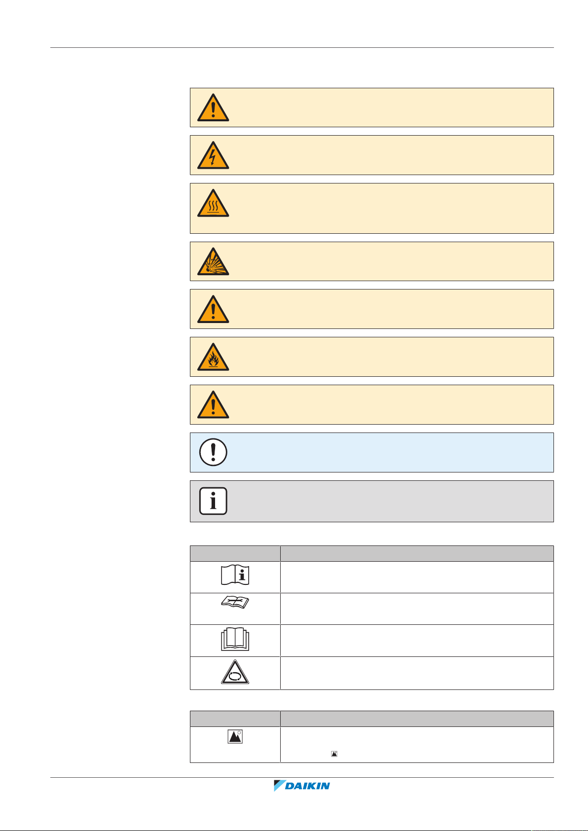
1.2 Meaning of warnings and symbols
DANGER
Indicates a situation that results in death or serious injury.
DANGER: RISK OF ELECTROCUTION
Indicates a situation that could result in electrocution.
DANGER: RISK OF BURNING/SCALDING
Indicates a situation that could result in burning/scalding because of extreme hot or
cold temperatures.
DANGER: RISK OF EXPLOSION
Indicates a situation that could result in explosion.
WARNING
Indicates a situation that could result in death or serious injury.
1 | About the documentation
WARNING: FLAMMABLE MATERIAL
CAUTION
Indicates a situation that could result in minor or moderate injury.
NOTICE
Indicates a situation that could result in equipment or property damage.
INFORMATION
Indicates useful tips or additional information.
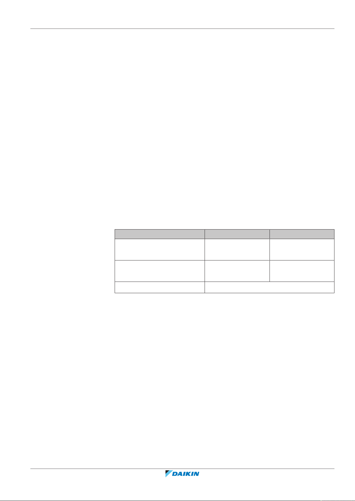
Symbols used on the unit:
Symbol Explanation
Before installation, read the installation and operation
manual, and the wiring instruction sheet.
Before performing maintenance and service tasks, read the
service manual.
For more information, see the installer and user reference
guide.
RXYQQ8~20U7Y1B
VRV IV Q+ series heat pump
4P546229-1A – 2020.10
The unit contains rotating parts. Be careful when servicing or
inspecting the unit.
Symbols used in the documentation:
Symbol Explanation
Indicates a figure title or a reference to it.
Example: " 1–3 Figure title" means "Figure 3 in chapter 1".
Installer and user reference guide
7
1 | About the documentation
Symbol Explanation
Indicates a table title or a reference to it.
Example: " 1–3 Table title" means "Table 3 in chapter 1".
Installer and user reference guide
8
RXYQQ8~20U7Y1B
VRV IV Q+ series heat pump
4P546229-1A – 2020.10
2 General safety precautions
In this chapter
2.1 For the installer....................................................................................................................................................................... 9
2.1.1 General ................................................................................................................................................................... 9
2.1.2 Installation site ....................................................................................................................................................... 10
2.1.3 Refrigerant — in case of R410A or R32 ................................................................................................................. 10
2.1.4 Electrical ................................................................................................................................................................. 12
2.1 For the installer
2.1.1 General
If you are NOT sure how to install or operate the unit, contact your dealer.
DANGER: RISK OF BURNING/SCALDING
▪ Do NOT touch the refrigerant piping, water piping or internal parts during and
immediately after operation. It could be too hot or too cold. Give it time to return
to normal temperature. If you must touch it, wear protective gloves.
▪ Do NOT touch any accidental leaking refrigerant.
2 | General safety precautions
WARNING
Improper installation or attachment of equipment or accessories could result in
electrical shock, short-circuit, leaks, fire or other damage to the equipment. Only use
accessories, optional equipment and spare parts made or approved by Daikin.
WARNING
Make sure installation, testing and applied materials comply with applicable
legislation (on top of the instructions described in the Daikin documentation).
CAUTION
Wear adequate personal protective equipment (protective gloves, safety glasses,…)
when installing, maintaining or servicing the system.
WARNING
Tear apart and throw away plastic packaging bags so that nobody, especially
children, can play with them. Possible risk: suffocation.
WARNING
Provide adequate measures to prevent that the unit can be used as a shelter by small
animals. Small animals that make contact with electrical parts can cause
malfunctions, smoke or fire.
RXYQQ8~20U7Y1B
VRV IV Q+ series heat pump
4P546229-1A – 2020.10
CAUTION
Do NOT touch the air inlet or aluminium fins of the unit.
Installer and user reference guide
9
2 | General safety precautions
In accordance with the applicable legislation, it might be necessary to provide a
logbook with the product containing at least: information on maintenance, repair
work, results of tests, stand-by periods,…
Also, at least, following information MUST be provided at an accessible place at the
product:
▪ Instructions for shutting down the system in case of an emergency
▪ Name and address of fire department, police and hospital
▪ Name, address and day and night telephone numbers for obtaining service
In Europe, EN378 provides the necessary guidance for this logbook.
CAUTION
▪ Do NOT place any objects or equipment on top of the unit.
▪ Do NOT sit, climb or stand on the unit.
NOTICE
Works executed on the outdoor unit are best done under dry weather conditions to
avoid water ingress.
2.1.2 Installation site
▪ Provide sufficient space around the unit for servicing and air circulation.
▪ Make sure the installation site withstands the weight and vibration of the unit.
▪ Make sure the area is well ventilated. Do NOT block any ventilation openings.
▪ Make sure the unit is level.
Do NOT install the unit in the following places:
▪ In potentially explosive atmospheres.
▪ In places where there is machinery that emits electromagnetic waves.
Electromagnetic waves may disturb the control system, and cause malfunction of
the equipment.
▪ In places where there is a risk of fire due to the leakage of flammable gases
(example: thinner or gasoline), carbon fibre, ignitable dust.
▪ In places where corrosive gas (example: sulphurous acid gas) is produced.
Corrosion of copper pipes or soldered parts may cause the refrigerant to leak.
2.1.3 Refrigerant — in case of R410A or R32
If applicable. See the installation manual or installer reference guide of your
application for more information.
Installer and user reference guide
10
NOTICE
Make sure refrigerant piping installation complies with applicable legislation. In
Europe, EN378 is the applicable standard.
NOTICE
Make sure the field piping and connections are NOT subjected to stress.
RXYQQ8~20U7Y1B
VRV IV Q+ series heat pump
4P546229-1A – 2020.10
2 | General safety precautions
WARNING
During tests, NEVER pressurize the product with a pressure higher than the
maximum allowable pressure (as indicated on the nameplate of the unit).
WARNING
Take sufficient precautions in case of refrigerant leakage. If refrigerant gas leaks,
ventilate the area immediately. Possible risks:
▪ Excessive refrigerant concentrations in a closed room can lead to oxygen
deficiency.
▪ Toxic gas might be produced if refrigerant gas comes into contact with fire.
DANGER: RISK OF EXPLOSION
Pump down – Refrigerant leakage. If you want to pump down the system, and there
is a leak in the refrigerant circuit:
▪ Do NOT use the unit's automatic pump down function, with which you can collect
all refrigerant from the system into the outdoor unit. Possible consequence: Selfcombustion and explosion of the compressor because of air going into the
operating compressor.
▪ Use a separate recovery system so that the unit's compressor does NOT have to
operate.
WARNING
ALWAYS recover the refrigerant. Do NOT release them directly into the environment.
Use a vacuum pump to evacuate the installation.
NOTICE
After all the piping has been connected, make sure there is no gas leak. Use nitrogen
to perform a gas leak detection.
NOTICE
▪ To avoid compressor breakdown, do NOT charge more than the specified amount
of refrigerant.
▪ When the refrigerant system is to be opened, refrigerant MUST be treated
according to the applicable legislation.
WARNING
Make sure there is no oxygen in the system. Refrigerant may only be charged after
performing the leak test and the vacuum drying.
Possible consequence: Self-combustion and explosion of the compressor because of
oxygen going into the operating compressor.
▪ In case recharge is required, see the nameplate of the unit. It states the type of
refrigerant and necessary amount.
RXYQQ8~20U7Y1B
VRV IV Q+ series heat pump
4P546229-1A – 2020.10
▪ The unit is factory charged with refrigerant and depending on pipe sizes and pipe
lengths some systems require additional charging of refrigerant.
▪ Only use tools exclusively for the refrigerant type used in the system, this to
ensure pressure resistance and prevent foreign materials from entering into the
system.
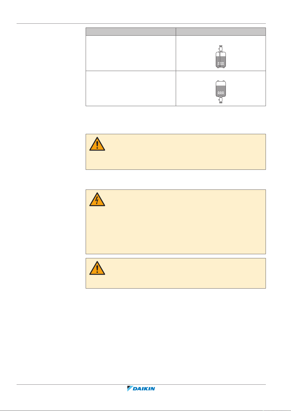
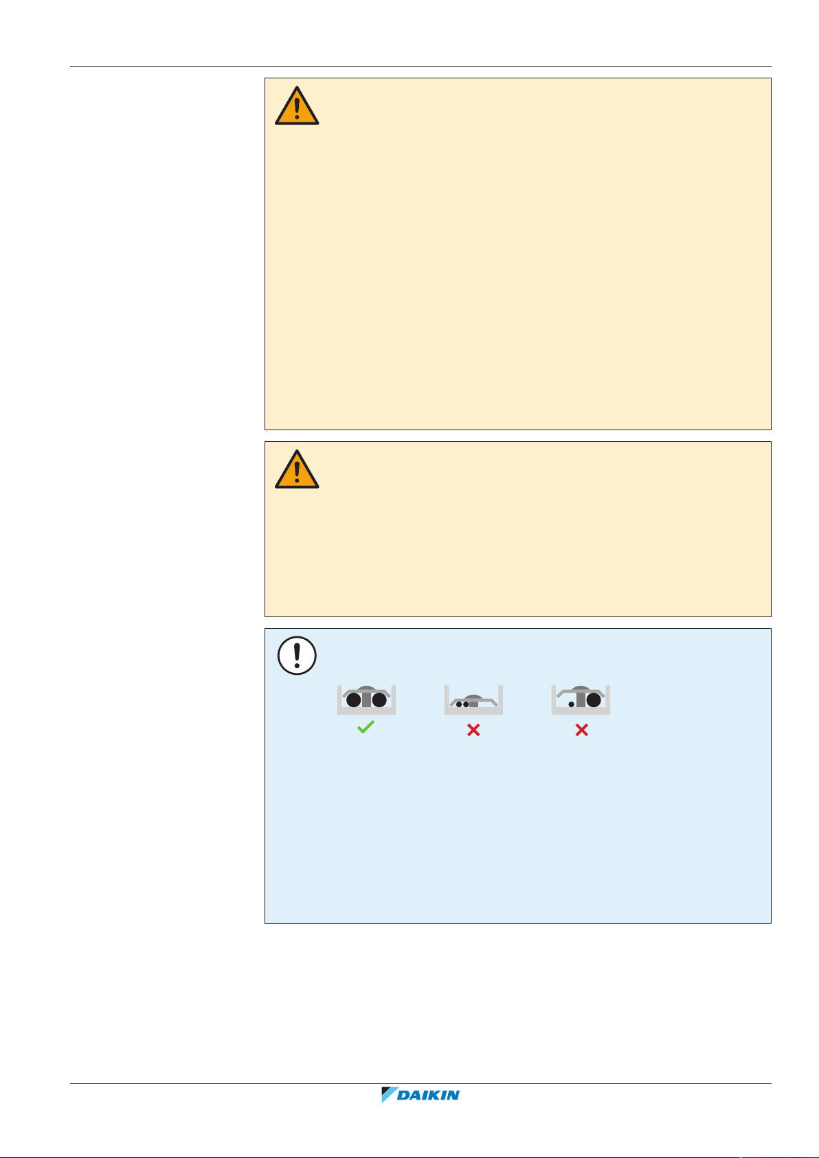
▪ Charge the liquid refrigerant as follows:
Installer and user reference guide
11
2 | General safety precautions
If Then
A siphon tube is present
Charge with the cylinder upright.
(i.e., the cylinder is marked with "Liquid
filling siphon attached")
A siphon tube is NOT present Charge with the cylinder upside down.
▪ Open refrigerant cylinders slowly.
▪ Charge the refrigerant in liquid form. Adding it in gas form may prevent normal
operation.
CAUTION
When the refrigerant charging procedure is done or when pausing, close the valve of
the refrigerant tank immediately. If the valve is NOT closed immediately, remaining
pressure might charge additional refrigerant. Possible consequence: Incorrect
refrigerant amount.
2.1.4 Electrical
DANGER: RISK OF ELECTROCUTION
▪ Turn OFF all power supply before removing the switch box cover, connecting
electrical wiring or touching electrical parts.
▪ Disconnect the power supply for more than 10minutes, and measure the voltage
at the terminals of main circuit capacitors or electrical components before
servicing. The voltage MUST be less than 50VDC before you can touch electrical
components. For the location of the terminals, see the wiring diagram.
▪ Do NOT touch electrical components with wet hands.
▪ Do NOT leave the unit unattended when the service cover is removed.
WARNING
If NOT factory installed, a main switch or other means for disconnection, having a
contact separation in all poles providing full disconnection under overvoltage
categoryIII condition, MUST be installed in the fixed wiring.
Installer and user reference guide
12
RXYQQ8~20U7Y1B
VRV IV Q+ series heat pump
4P546229-1A – 2020.10
2 | General safety precautions
WARNING
▪ ONLY use copper wires.
▪ Make sure the field wiring complies with the applicable legislation.
▪ All field wiring MUST be performed in accordance with the wiring diagram
supplied with the product.
▪ NEVER squeeze bundled cables and make sure they do NOT come in contact with
the piping and sharp edges. Make sure no external pressure is applied to the
terminal connections.
▪ Make sure to install earth wiring. Do NOT earth the unit to a utility pipe, surge
absorber, or telephone earth. Incomplete earth may cause electrical shock.
▪ Make sure to use a dedicated power circuit. NEVER use a power supply shared by
another appliance.
▪ Make sure to install the required fuses or circuit breakers.
▪ Make sure to install an earth leakage protector. Failure to do so may cause
electrical shock or fire.
▪ When installing the earth leakage protector, make sure it is compatible with the
inverter (resistant to high frequency electric noise) to avoid unnecessary opening
of the earth leakage protector.
CAUTION
▪ When connecting the power supply: connect the earth cable first, before making
the current-carrying connections.
▪ When disconnecting the power supply: disconnect the current-carrying cables
first, before separating the earth connection.
▪ The length of the conductors between the power supply stress relief and the
terminal block itself must be as such that the current-carrying wires are tautened
before the earth wire is in case the power supply is pulled loose from the stress
relief.
NOTICE
Precautions when laying power wiring:
▪ Do NOT connect wiring of different thicknesses to the power terminal block (slack
in the power wiring may cause abnormal heat).
▪ When connecting wiring which is the same thickness, do as shown in the figure
above.
▪ For wiring, use the designated power wire and connect firmly, then secure to
prevent outside pressure being exerted on the terminal board.
▪ Use an appropriate screwdriver for tightening the terminal screws. A screwdriver
with a small head will damage the head and make proper tightening impossible.
▪ Over-tightening the terminal screws may break them.
RXYQQ8~20U7Y1B
VRV IV Q+ series heat pump
4P546229-1A – 2020.10
Install power cables at least 1 m away from televisions or radios to prevent
interference. Depending on the radio waves, a distance of 1 m may not be
sufficient.
Installer and user reference guide
13
2 | General safety precautions
WARNING
▪ After finishing the electrical work, confirm that each electrical component and
terminal inside the electrical components box is connected securely.
▪ Make sure all covers are closed before starting up the unit.
NOTICE
Only applicable if the power supply is three‑phase, and the compressor has an ON/
OFF starting method.
If there exists the possibility of reversed phase after a momentary black out and the
power goes on and off while the product is operating, attach a reversed phase
protection circuit locally. Running the product in reversed phase can break the
compressor and other parts.
Installer and user reference guide
14
RXYQQ8~20U7Y1B
VRV IV Q+ series heat pump
4P546229-1A – 2020.10
3 | Specific installer safety instructions
3 Specific installer safety instructions
Always observe the following safety instructions and regulations.
WARNING
Tear apart and throw away plastic packaging bags so that nobody, especially
children, can play with them. Possible risk: suffocation.
CAUTION
Appliance not accessible to the general public, install it in a secured area, protected
from easy access.
This unit, both indoor and outdoor, is suitable for installation in a commercial and
light industrial environment.
CAUTION
Excessive refrigerant concentrations in a closed room can lead to oxygen deficiency.
DANGER: RISK OF ELECTROCUTION
Do NOT leave the unit unattended when the service cover is removed.
DANGER: RISK OF BURNING/SCALDING
DANGER: RISK OF ELECTROCUTION
WARNING
Take sufficient precautions in case of refrigerant leakage. If refrigerant gas leaks,
ventilate the area immediately. Possible risks:
▪ Excessive refrigerant concentrations in a closed room can lead to oxygen
deficiency.
▪ Toxic gas might be produced if refrigerant gas comes into contact with fire.
WARNING
ALWAYS recover the refrigerant. Do NOT release them directly into the environment.
Use a vacuum pump to evacuate the installation.
WARNING
During tests, NEVER pressurize the product with a pressure higher than the
maximum allowable pressure (as indicated on the nameplate of the unit).
RXYQQ8~20U7Y1B
VRV IV Q+ series heat pump
4P546229-1A – 2020.10
CAUTION
Do not vent gases into the atmosphere.
WARNING
Any gas or oil remaining inside the stop valve may blow off the spun piping.
If these instructions are NOT followed correctly it may result in property damage or
personal injury, which may be serious depending on the circumstances.
Installer and user reference guide
15
3 | Specific installer safety instructions
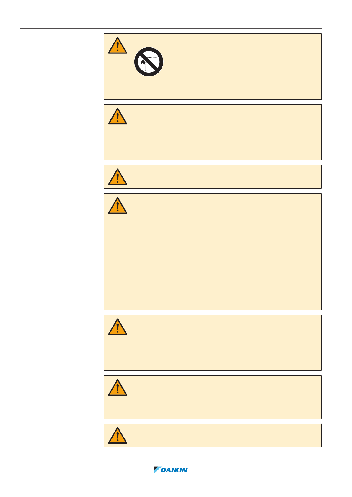
WARNING
NEVER remove the spun piping by brazing.
Any gas or oil remaining inside the stop valve may blow off the spun piping.
WARNING
▪ ONLY use R410A as refrigerant. Other substances may cause explosions and
accidents.
▪ R410A contains fluorinated greenhouse gases. Its global warming potential (GWP)
value is 2087.5. Do NOT vent these gases into the atmosphere.
▪ When charging refrigerant, ALWAYS use protective gloves and safety glasses.
CAUTION
Do NOT push or place redundant cable length in the unit.
WARNING
▪ If the power supply has a missing or wrong N-phase, equipment might break
down.
▪ Establish proper earthing. Do NOT earth the unit to a utility pipe, surge absorber,
or telephone earth. Incomplete earthing may cause electrical shock.
▪ Install the required fuses or circuit breakers.
▪ Secure the electrical wiring with cable ties so that the cables do NOT come in
contact with sharp edges or piping, particularly on the high-pressure side.
▪ Do NOT use taped wires, stranded conductor wires, extension cords, or
connections from a star system. They can cause overheating, electrical shock or
fire.
▪ Do NOT install a phase advancing capacitor, because this unit is equipped with an
inverter. A phase advancing capacitor will reduce performance and may cause
accidents.
WARNING
▪ All wiring MUST be performed by an authorised electrician and MUST comply
with the applicable legislation.
▪ Make electrical connections to the fixed wiring.
▪ All components procured on-site and all electrical construction MUST comply
with the applicable legislation.
Installer and user reference guide
16
WARNING
For the existing power supply and transmission wiring, check that the specifications
match the requirements described in this chapter and that other parts (especially
terminals) do not appear to have deteriorated. Take the appropriate steps (e.g.
replacement) if necessary.
WARNING
ALWAYS use multicore cable for power supply cables.
RXYQQ8~20U7Y1B
VRV IV Q+ series heat pump
4P546229-1A – 2020.10
3 | Specific installer safety instructions
CAUTION
▪ When connecting the power supply: connect the earth cable first, before making
the current-carrying connections.
▪ When disconnecting the power supply: disconnect the current-carrying cables
first, before separating the earth connection.
▪ The length of the conductors between the power supply stress relief and the
terminal block itself must be as such that the current-carrying wires are tautened
before the earth wire is in case the power supply is pulled loose from the stress
relief.
CAUTION
Do NOT perform the test operation while working on the indoor units.
When performing the test operation, NOT only the outdoor unit, but the connected
indoor unit will operate as well. Working on an indoor unit while performing a test
operation is dangerous.
CAUTION
Do NOT insert fingers, rods or other objects into the air inlet or outlet. Do NOT
remove the fan guard. When the fan is rotating at high speed, it will cause injury.
RXYQQ8~20U7Y1B
VRV IV Q+ series heat pump
4P546229-1A – 2020.10
Installer and user reference guide
17

For the user
For the user
Installer and user reference guide
18
RXYQQ8~20U7Y1B
VRV IV Q+ series heat pump
4P546229-1A – 2020.10
4 User safety instructions
Always observe the following safety instructions and regulations.
In this chapter
4.1 General.................................................................................................................................................................................... 19
4.2 Instructions for safe operation............................................................................................................................................... 20
4.1 General
WARNING
If you are NOT sure how to operate the unit, contact your
installer.
WARNING
Children aged from 8 years and above and persons with
reduced physical, sensory or mental capabilities or lack of
experience and knowledge can only use this appliance if
they have been given supervision or instruction concerning
the use of the appliance by a person responsible for their
safety.
4 | User safety instructions
Children MUST NOT play with the appliance.
Cleaning and user maintenance MUST NOT be carried out
by children without supervision.
WARNING
To prevent electrical shocks or fire:
▪ Do NOT rinse the unit.
▪ Do NOT operate the unit with wet hands.
▪ Do NOT place any objects containing water on the unit.
CAUTION
▪ Do NOT place any objects or equipment on top of the
unit.
▪ Do NOT sit, climb or stand on the unit.
RXYQQ8~20U7Y1B
VRV IV Q+ series heat pump
4P546229-1A – 2020.10
Installer and user reference guide
19
4 | User safety instructions
▪ Units are marked with the following symbol:
▪ Batteries are marked with the following symbol:
This means that electrical and electronic products may NOT be mixed with
unsorted household waste. Do NOT try to dismantle the system yourself: the
dismantling of the system, treatment of the refrigerant, of oil and of other parts
must be done by an authorized installer and must comply with applicable
legislation.
Units must be treated at a specialized treatment facility for reuse, recycling and
recovery. By ensuring this product is disposed of correctly, you will help to
prevent potential negative consequences for the environment and human
health. For more information, contact your installer or local authority.
This means that the batteries may NOT be mixed with unsorted household
waste. If a chemical symbol is printed beneath the symbol, this chemical symbol
means that the battery contains a heavy metal above a certain concentration.
Possible chemical symbols are: Pb: lead (>0.004%).
Waste batteries must be treated at a specialized treatment facility for reuse. By
ensuring waste batteries are disposed of correctly, you will help to prevent
potential negative consequences for the environment and human health.
4.2 Instructions for safe operation
CAUTION
▪ NEVER touch the internal parts of the controller.
▪ Do NOT remove the front panel. Some parts inside are
dangerous to touch and appliance problems may
happen. For checking and adjusting the internal parts,
contact your dealer.
CAUTION
Do NOT operate the system when using a room
fumigation-type insecticide. Chemicals could collect in the
unit, and endanger the health of people who are
hypersensitive to chemicals.
Installer and user reference guide
20
CAUTION
It is unhealthy to expose your body to the air flow for a
long time.
RXYQQ8~20U7Y1B
VRV IV Q+ series heat pump
4P546229-1A – 2020.10
4 | User safety instructions
CAUTION
To avoid oxygen deficiency, ventilate the room sufficiently
if equipment with burner is used together with the system.
WARNING
This unit contains electrical and hot parts.
WARNING
Before operating the unit, be sure the installation has been
carried out correctly by an installer.
WARNING
Never touch the air outlet or the horizontal blades while
the swing flap is in operation. Fingers may become caught
or the unit may break down.
CAUTION
Do NOT insert fingers, rods or other objects into the air
inlet or outlet. Do NOT remove the fan guard. When the
fan is rotating at high speed, it will cause injury.
CAUTION: Pay attention to the fan!
It is dangerous to inspect the unit while the fan is running.
Be sure to turn off the main switch before executing any
maintenance task.
CAUTION
After a long use, check the unit stand and fitting for
damage. If damaged, the unit may fall and result in injury.
WARNING
NEVER replace a fuse with a fuse of a wrong ampere
ratings or other wires when a fuse blows out. Use of wire
or copper wire may cause the unit to break down or cause
a fire.
RXYQQ8~20U7Y1B
VRV IV Q+ series heat pump
4P546229-1A – 2020.10
Installer and user reference guide
21
4 | User safety instructions
WARNING
▪ Do NOT modify, disassemble, remove, reinstall or repair
the unit yourself as incorrect dismantling or installation
may cause an electric shock or fire. Contact your dealer.
▪ In case of accidental refrigerant leaks, make sure there
are no naked flames. The refrigerant itself is entirely
safe, non-toxic and non-combustible, but it will generate
toxic gas when it accidentally leaks into a room where
combustible air from fan heaters, gas cookers, etc. is
present. Always have qualified service personnel
confirm that the point of leakage has been repaired or
corrected before resuming operation.
WARNING
Stop operation and shut off the power if anything
unusual occurs (burning smells etc.).
Leaving the unit running under such circumstances may
cause breakage, electric shock or fire. Contact your dealer.
WARNING
The refrigerant in the system is safe and normally does not
leak. If the refrigerant leaks in the room, contact with a fire
of a burner, a heater or a cooker may result in a harmful
gas.
Turn off any combustible heating devices, ventilate the
room and contact the dealer where you purchased the
unit.
Do not use the system until a service person confirms that
the portion where the refrigerant leaks is repaired.
CAUTION
NEVER expose little children, plants or animals directly to
the airflow.
Installer and user reference guide
22
CAUTION
Do NOT touch the heat exchanger fins. These fins are
sharp and could result in cutting injuries.
RXYQQ8~20U7Y1B
VRV IV Q+ series heat pump
4P546229-1A – 2020.10
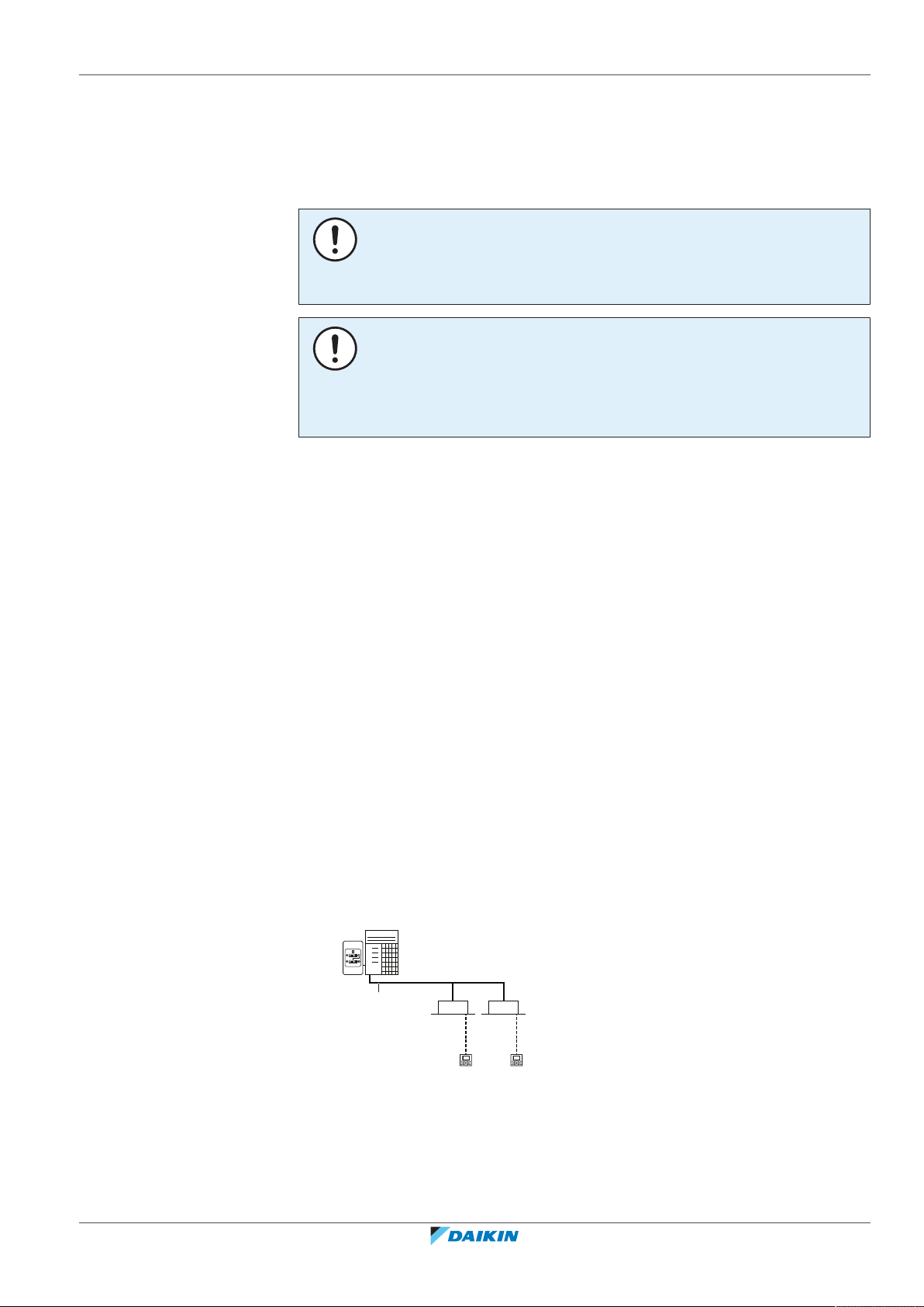
5 About the system
a
e
c
d d
c
b
The indoor unit part of VRV IV replacement heat pump system can be used for
heating/cooling applications. The type of indoor unit which can be used depends
on the outdoor units series.
NOTICE
Do NOT use the system for other purposes. In order to avoid any quality
deterioration, do NOT use the unit for cooling precision instruments, food, plants,
animals, or works of art.
NOTICE
For future modifications or expansions of your system:
A full overview of allowable combinations (for future system extensions) is available
in technical engineering data and should be consulted. Contact your installer to
receive more information and professional advice.
In general following type of indoor units can be connected to a VRV IV replacement
heat pump system (not exhaustive list, depending on outdoor unit model and
indoor unit model combinations):
5 | About the system
▪ VRV direct expansion (DX) indoor units for R410A (air to air applications).
▪ AHU (air to air applications): EKEXV-kit+EKEQ-box are required, depending on the
application.
▪ VRV direct expansion (DX) indoor units for non-R410A (air to air applications).
See "Possible combinations of indoor units"[457].
Airhandling unit connection in pair to VRV IV replacement heat pump outdoor unit
is supported.
Airhandling unit connection in multi to VRV IV replacement heat pump outdoor
unit is supported, even combined with VRV direct expansion indoor unit(s).
For more specifications, see technical engineering data.
In this chapter
5.1 System layout.......................................................................................................................................................................... 23
5.1 System layout
a VRV IV replacement heat pump outdoor unit
b Refrigerant piping
c VRV direct expansion (DX) indoor unit
d User interface (dedicated depending on indoor unit type)
e Cool/Heat changeover remote control switch
RXYQQ8~20U7Y1B
VRV IV Q+ series heat pump
4P546229-1A – 2020.10
Installer and user reference guide
23

6 | User interface
6 User interface
CAUTION
▪ NEVER touch the internal parts of the controller.
▪ Do NOT remove the front panel. Some parts inside are dangerous to touch and
appliance problems may happen. For checking and adjusting the internal parts,
contact your dealer.
This operation manual offers a non-exhaustive overview of the main functions of
the system.
Detailed information on required actions to achieve certain functions can be found
in the dedicated installation and operation manual of the indoor unit.
Refer to the operation manual of the installed user interface.
Installer and user reference guide
24
RXYQQ8~20U7Y1B
VRV IV Q+ series heat pump
4P546229-1A – 2020.10
7 Before operation
WARNING
Ask your dealer for improvement, repair, and maintenance. Incomplete
improvement, repair, and maintenance may result in water leakage, electric shock
and fire.
WARNING
Ask your dealer to move and reinstall the air conditioner. Incomplete installation may
result in a water leakage, electric shock, and fire.
WARNING
NEVER let the indoor unit or the user interface get wet. It may cause an electric
shock or a fire.
WARNING
Do NOT place objects in direct proximity of the outdoor unit and do NOT let leaves
and other debris accumulate around the unit. Leaves are a hotbed for small animals
which can enter the unit. Once in the unit, such animals can cause malfunctions,
smoke or fire when making contact with electrical parts.
7 | Before operation
WARNING
Avoid placing the user interface in a place where it can be splashed with water.
Water entering the machine may cause an electric leak or may damage the internal
electronic parts.
WARNING
This unit contains electrical and hot parts.
WARNING
Before operating the unit, be sure the installation has been carried out correctly by
an installer.
NOTICE
NEVER inspect or service the unit by yourself. Ask a qualified service person to
perform this work.
CAUTION
Do NOT touch the heat exchanger fins. These fins are sharp and could result in
cutting injuries.
RXYQQ8~20U7Y1B
VRV IV Q+ series heat pump
4P546229-1A – 2020.10
WARNING
Do NOT place a flammable spray bottle near the air conditioner and do NOT use
sprays near the unit. Doing so may result in a fire.
CAUTION
It is unhealthy to expose your body to the air flow for a long time.
Installer and user reference guide
25
7 | Before operation
CAUTION
To avoid oxygen deficiency, ventilate the room sufficiently if equipment with burner
is used together with the system.
CAUTION
Do NOT operate the system when using a room fumigation-type insecticide.
Chemicals could collect in the unit, and endanger the health of people who are
hypersensitive to chemicals.
CAUTION
NEVER expose little children, plants or animals directly to the airflow.
NOTICE
NEVER press the button of the user interface with a hard, pointed object. The user
interface may be damaged.
NOTICE
NEVER pull or twist the electric wire of the user interface. It may cause the unit to
malfunction.
NOTICE
Do NOT place the user interface in a place exposed to direct sunlight. The LCD display
may get discoloured or fail to display the data.
NOTICE
Do NOT place items which might be damaged by moisture under the indoor unit.
Condensation may form if the humidity is above 80%, if the drain outlet is blocked or
the filter is polluted.
NOTICE
Arrange the drain hose to ensure smooth drainage. Incomplete drainage may cause
the building, furniture, etc. to get wet.
NOTICE
Be sure to turn ON the power 6 hours before operation in order to have power
running to the crankcase heater and to protect the compressor.
This operation manual is for the following systems with standard control. Before
initiating operation, contact your dealer for the operation that corresponds to your
system type and mark. If your installation has a customised control system, ask
your dealer for the operation that corresponds to your system.
Installer and user reference guide
26
Operation modes (depending on indoor unit type):
▪ Heating and cooling (air to air).
▪ Fan only operation (air to air).
Dedicated functions exist depending on the type of indoor unit, refer to dedicated
installation/operation manual for more information.
RXYQQ8~20U7Y1B
VRV IV Q+ series heat pump
4P546229-1A – 2020.10
8 Operation
In this chapter
8.1 Operation range...................................................................................................................................................................... 27
8.2 Operating the system ............................................................................................................................................................. 27
8.3 Using the dry program............................................................................................................................................................ 30
8.4 Adjusting the air flow direction.............................................................................................................................................. 31
8.5 Setting the master user interface .......................................................................................................................................... 32
8.6 About control systems............................................................................................................................................................ 33
8 | Operation
8.2.1 About operating the system .................................................................................................................................. 27
8.2.2 About cooling, heating, fan only, and automatic operation ................................................................................. 28
8.2.3 About the heating operation ................................................................................................................................. 28
8.2.4 To operate the system (WITHOUT cool/heat changeover remote control switch) ............................................. 29
8.2.5 To operate the system (WITH cool/heat changeover remote control switch)..................................................... 29
8.3.1 About the dry program .......................................................................................................................................... 30
8.3.2 To use the dry program (WITHOUT cool/heat changeover remote control switch)............................................ 30
8.3.3 To use the dry program (WITH cool/heat changeover remote control switch) ................................................... 30
8.4.1 About the air flow flap ........................................................................................................................................... 31
8.5.1 About setting the master user interface ............................................................................................................... 32
8.5.2 To designate the master user interface (VRV DX and Hydrobox) ......................................................................... 33
8.1 Operation range
Use the system in the following temperature and humidity ranges for safe and
effective operation.
Outdoor temperature –5~43°CDB –20~21°CDB
Indoor temperature 21~32°CDB
Indoor humidity ≤80%
(a)
To avoid condensation and water dripping out of the unit. If the temperature or the
humidity is beyond these conditions, safety devices may be put in action and the air
conditioner may not operate.
Above operation range is only valid in case direct expansion indoor units are
connected to the VRV IV system.
8.2 Operating the system
Cooling Heating
–20~15.5°C WB
15~27°CDB
14~25°C WB
(a)
8.2.1 About operating the system
RXYQQ8~20U7Y1B
VRV IV Q+ series heat pump
4P546229-1A – 2020.10
▪ Operation procedure varies according to the combination of outdoor unit and
user interface.
▪ To protect the unit, turn on the main power switch 6 hours before operation.
▪ If the main power supply is turned off during operation, operation will restart
automatically after the power turns back on again.
Installer and user reference guide
27
8 | Operation
8.2.2 About cooling, heating, fan only, and automatic operation
8.2.3 About the heating operation
▪ Changeover cannot be made with a user interface whose display shows
"change-over under centralised control" (refer to installation and operation
manual of the user interface).
▪ When the display "change-over under centralised control" flashes, refer to
"About setting the master user interface"[432].
▪ The fan may keep on running for about 1 minute after the heating operation
stops.
▪ The air flow rate may adjust itself depending on the room temperature or the fan
may stop immediately. This is not a malfunction.
It may take longer to reach the set temperature for general heating operation than
for cooling operation.
The following operation is performed in order to prevent the heating capacity from
dropping or cold air from blowing.
Defrost operation
In heating operation, freezing of the outdoor unit's air cooled coil increases over
time, restricting the energy transfer to the outdoor unit's coil. Heating capability
decreases and the system needs to go into defrost operation to be able to remove
frost from the outdoor unit’s coil. During defrost operation the heating capacity on
the indoor unit side will temporarily drop until defrosting is completed. After
defrosting, the unit will regain its full heating capacity.
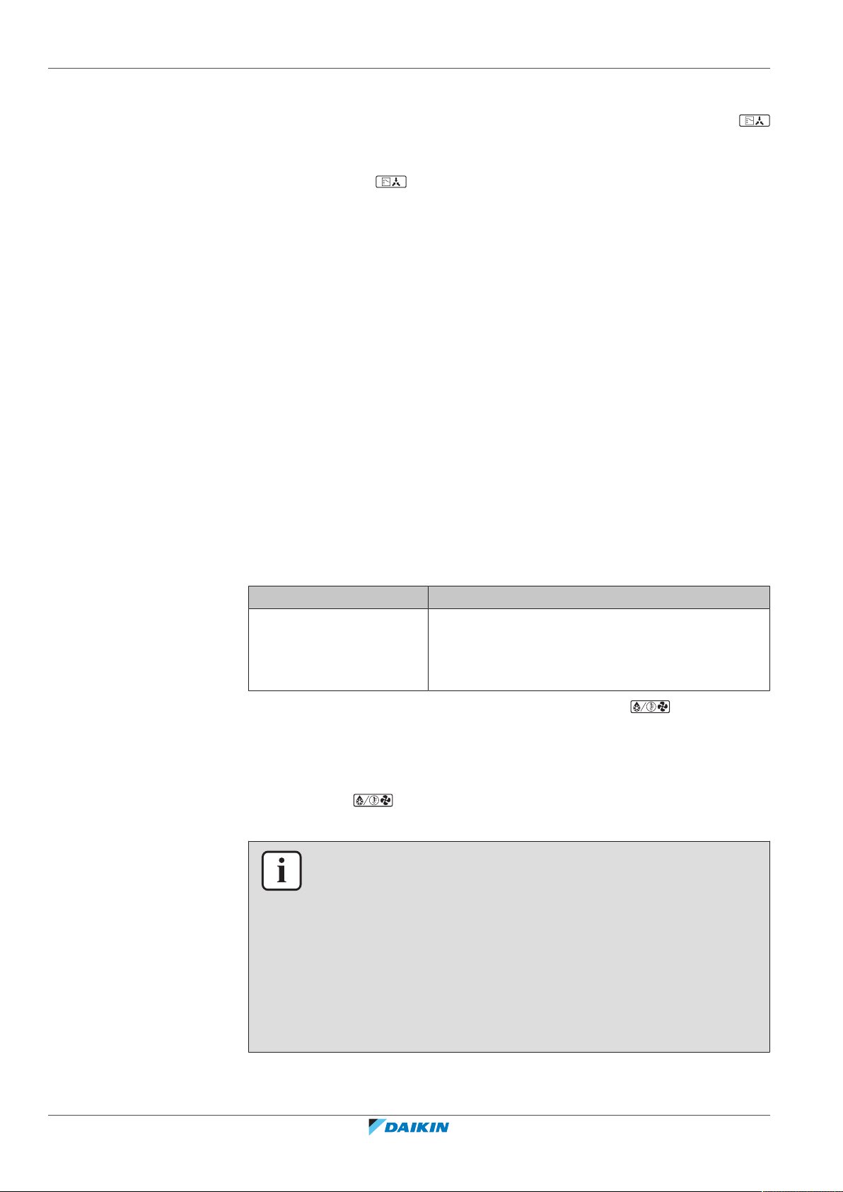
If Then
RXYQQ outdoor unit is
installed
The indoor unit will stop fan operation, the
refrigerant cycle will reverse and energy from inside
the building will be used to defrost the outdoor unit
coil.
The indoor unit will indicate defrost operation on the display .
Hot start
In order to prevent cold air from blowing out of an indoor unit at the start of
heating operation, the indoor fan is automatically stopped. The display of the user
interface shows . It may take some time before the fan starts. This is not a
malfunction.
INFORMATION
▪ The heating capacity drops when the outside temperature falls. If this happens,
use another heating device together with the unit. (When using together with
appliances that produce open fire, ventilate the room constantly). Do not place
appliances that produce open fire in places exposed to the air flow from the unit
or under the unit.
▪ It takes some time to heat up the room from the time the unit is started since the
unit uses a hot-air circulating system to heat the entire room.
▪ If the hot air rises to the ceiling, leaving the area above the floor cold, we
recommend that you use the circulator (the indoor fan for circulating air).
Contact your dealer for details.
Installer and user reference guide
28
RXYQQ8~20U7Y1B
VRV IV Q+ series heat pump
4P546229-1A – 2020.10
8 | Operation
a
b
1
1
1
1
1
8.2.4 To operate the system (WITHOUT cool/heat changeover remote control switch)
1 Press the operation mode selector button on the user interface several times
and select the operation mode of your choice.
Cooling operation
Heating operation
Fan only operation
2 Press the ON/OFF button on the user interface.
Result: The operation lamp lights up and the system starts operating.
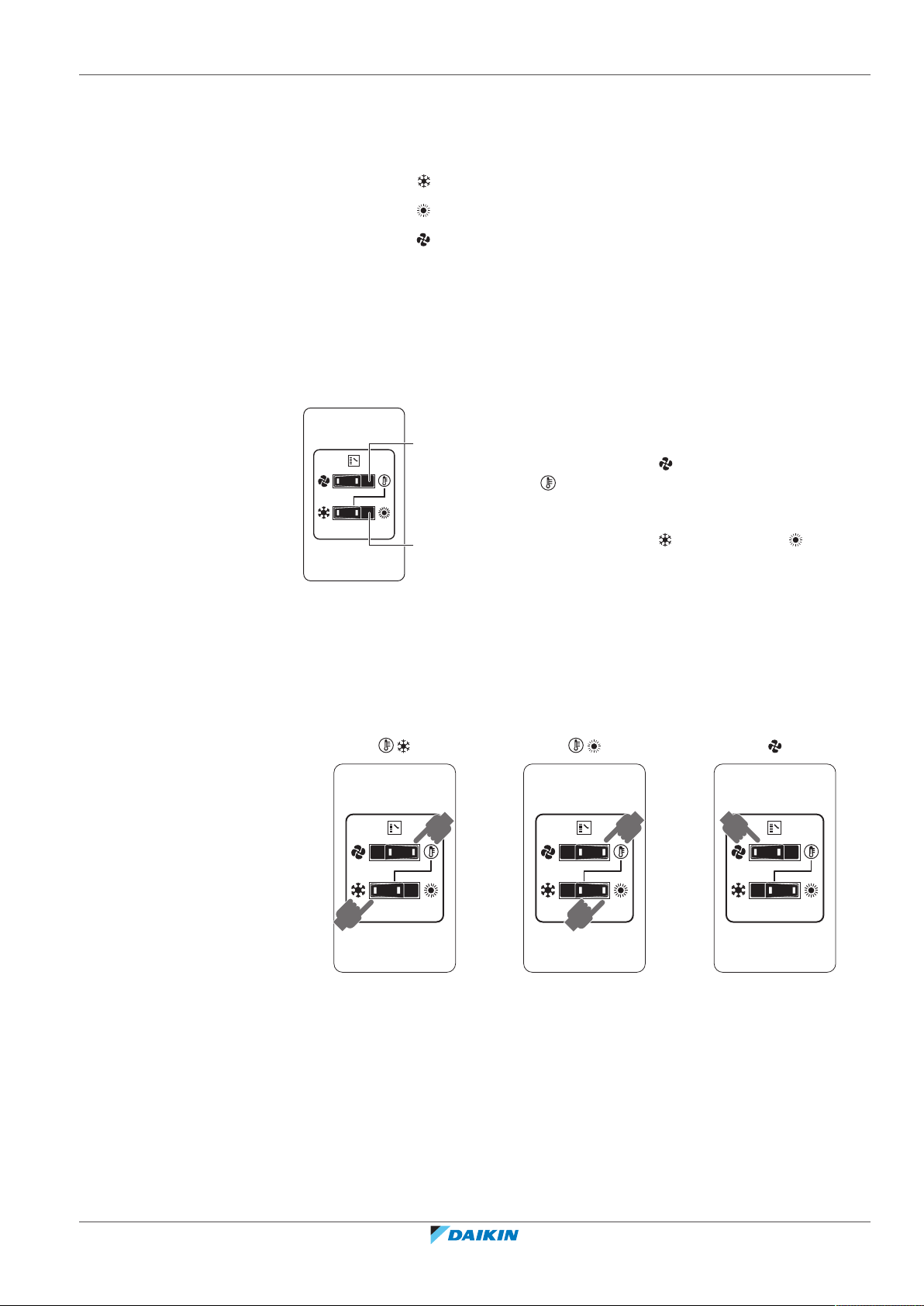
8.2.5 To operate the system (WITH cool/heat changeover remote control switch)
Overview of the changeover remote control switch
a FAN ONLY/AIR CONDITIONING SELECTOR
SWITCH
Set the switch to for fan only operation or to
for heating or cooling operation.
b COOL/HEAT CHANGEOVER SWITCH
Set the switch to for cooling or to for
heating
Note: In case a cool/heat changeover remote control switch is used, the position of
DIP switch 1 (DS1-1) on the main PCB needs to be switched to the ON position.
To start
1 Select operation mode with the cool/heat changeover switch as follows:
Cooling operation
Heating operation
Fan only operation
2 Press the ON/OFF button on the user interface.
Result: The operation lamp lights up and the system starts operating.
To stop
3 Press the ON/OFF button on the user interface once again.
Result: The operation lamp goes out and the system stops operating.
RXYQQ8~20U7Y1B
VRV IV Q+ series heat pump
4P546229-1A – 2020.10
Installer and user reference guide
29
8 | Operation
8.3 Using the dry program
8.3.1 About the dry program
NOTICE
Do not turn off power immediately after the unit stops, but wait for at least 5
minutes.
To adjust
For programming temperature, fan speed and air flow direction refer to the
operation manual of the user interface.
▪ The function of this program is to decrease the humidity in your room with
minimal temperature decrease (minimal room cooling).
▪ The micro computer automatically determines temperature and fan speed
(cannot be set by the user interface).
▪ The system does not go into operation if the room temperature is low (<20°C).
8.3.2 To use the dry program (WITHOUT cool/heat changeover remote control switch)
To start
1 Press the operation mode selector button on the user interface several times
and select (program dry operation).
2 Press the ON/OFF button of the user interface.
Result: The operation lamp lights up and the system starts operating.
3 Press the air flow direction adjust button (only for double-flow, multi-flow,
corner, ceiling-suspended and wall-mounted). Refer to "8.4 Adjusting the air
flow direction"[431] for details.
To stop
4 Press the ON/OFF button on the user interface once again.
Result: The operation lamp goes out and the system stops operating.
NOTICE
Do not turn off power immediately after the unit stops, but wait for at least 5
minutes.
8.3.3 To use the dry program (WITH cool/heat changeover remote control switch)
Installer and user reference guide
30
To start
1 Select cooling operation mode with the cool/heat changeover remote control
switch.
RXYQQ8~20U7Y1B
VRV IV Q+ series heat pump
4P546229-1A – 2020.10

8 | Operation
1
1
2 Press the operation mode selector button on the user interface several times
and select (program dry operation).
3 Press the ON/OFF button of the user interface.
Result: The operation lamp lights up and the system starts operating.
4 Press the air flow direction adjust button (only for double-flow, multi-flow,
corner, ceiling-suspended and wall-mounted). Refer to "8.4 Adjusting the air
flow direction"[431] for details.
To stop
5 Press the ON/OFF button on the user interface once again.
Result: The operation lamp goes out and the system stops operating.
NOTICE
Do not turn off power immediately after the unit stops, but wait for at least 5
minutes.
8.4 Adjusting the air flow direction
Refer to the operation manual of the user interface.
8.4.1 About the air flow flap
Double flow+multi-flow units
Corner units
Ceiling suspended units
Wall-mounted units
RXYQQ8~20U7Y1B
VRV IV Q+ series heat pump
4P546229-1A – 2020.10
For the following conditions, a micro computer controls the air flow direction
which may be different from the display.
Cooling Heating
▪ When the room temperature is lower
than the set temperature.
▪ When starting operation.
▪ When the room temperature is higher
than the set temperature.
▪ At defrost operation.
Installer and user reference guide
31

8 | Operation
c c
b
b
a
Cooling Heating
▪ When operating continuously at horizontal air flow direction.
▪ When continuous operation with downward air flow is performed at the time of
cooling with a ceiling-suspended or a wall-mounted unit, the micro computer
may control the flow direction, and then the user interface indication will also
change.
The air flow direction can be adjusted in one of the following ways:
▪ The air flow flap itself adjusts its position.
▪ The air flow direction can be fixed by the user.
▪ Automatic and desired position .
WARNING
Never touch the air outlet or the horizontal blades while the swing flap is in
operation. Fingers may become caught or the unit may break down.
NOTICE
▪ The movable limit of the flap is changeable. Contact your dealer for details. (only
for double-flow, multi-flow, corner, ceiling-suspended and wall-mounted).
▪ Avoid operating in the horizontal direction . It may cause dew or dust to
settle on the ceiling or flap.
8.5 Setting the master user interface
8.5.1 About setting the master user interface
a VRV replacement heat pump outdoor unit
b VRV direct expansion (DX) indoor unit
c User interface (dedicated depending on indoor unit type)
When the system is installed as shown in the figure above, it is necessary to
designate one of the user interfaces as the master user interface.
The displays of slave user interfaces show (change-over under centralised
control) and slave user interfaces automatically follow the operation mode
directed by the master user interface.
Only the master user interface can select heating or cooling mode.
Installer and user reference guide
32
RXYQQ8~20U7Y1B
VRV IV Q+ series heat pump
4P546229-1A – 2020.10

8.5.2 To designate the master user interface (VRV DX and Hydrobox)
1 Press the operation mode selector button of the current master user interface
for 4 seconds. In case this procedure was not yet performed, the procedure
can be executed on the first user interface operated.
Result: The display showing (change-over under centralised control) of
all slave user interfaces connected to the same outdoor unit flashes.
2 Press the operation mode selector button of the controller that you wish to
designate as the master user interface.
Result: Designation is completed. This user interface is designated as the
master user interface and the display showing (change-over under
centralised control) vanishes. The displays of other user interfaces show
(change-over under centralised control).
8.6 About control systems
This system provides two other control systems beside individual control system
(one user interface controls one indoor unit). Confirm the following if your unit is
of the following control system type:
8 | Operation
Type Description
Group control system 1 user interface controls up to 16 indoor units.
All indoor units are equally set.
2 user interface control system 2 user interfaces control 1 indoor unit (in case of
group control system, 1 group of indoor units).
The unit is individually operated.
NOTICE
Contact your dealer in case of changing the combination or setting of group control
and 2 user interface control systems.
RXYQQ8~20U7Y1B
VRV IV Q+ series heat pump
4P546229-1A – 2020.10
Installer and user reference guide
33

9 | Energy saving and optimum operation
9 Energy saving and optimum operation
Observe the following precautions to ensure the system operates properly.
▪ Adjust the air outlet properly and avoid direct air flow to room inhabitants.
▪ Adjust the room temperature properly for a comfortable environment. Avoid
excessive heating or cooling.
▪ Prevent direct sunlight from entering a room during cooling operation by using
curtains or blinds.
▪ Ventilate often. Extended use requires special attention to ventilation.
▪ Keep doors and windows closed. If the doors and windows remain open, air will
flow out of your room causing a decrease in the cooling or heating effect.
▪ Be careful NOT to cool or heat too much. To save energy, keep the temperature
setting at a moderate level.
▪ NEVER place objects near the air inlet or the air outlet of the unit. Doing so may
cause a reduced heating/cooling effect or stop operation.
▪ Turn off the main power supply switch to the unit when the unit is not used for
longer periods of time. If the switch is on, it consumes electricity. Before
restarting the unit, turn on the main power supply switch 6 hours before
operation to ensure smooth running. (Refer to "Maintenance" in the indoor unit
manual.)
▪ When the display shows (time to clean the air filter), ask a qualified service
person to clean the filters. (Refer to "Maintenance" in the indoor unit manual.)
▪ Keep the indoor unit and user interface at least 1 m away from televisions,
radios, stereos, and other similar equipment. Failing to do so may cause static or
distorted pictures.
▪ Do NOT place items under the indoor unit, as they may be damaged by water.
▪ Condensation may form if the humidity is above 80% or if the drain outlet gets
blocked.
This VRV IV replacement heat pump system is equipped with advanced energy
saving functionality. Depending on the priority, emphasises can be put on energy
saving or comfort level. Several parameters can be selected, resulting in the
optimal balance between energy consumption and comfort for the particular
application.
Several patterns are available and roughly explained below. Contact your installer
or dealer for advice or to modify the parameters to the needs of your building.
Detailed information is given for the installer in the installation manual. He can
help you to realize the best balance between energy consumption and comfort.
In this chapter
9.1 Available main operation methods ........................................................................................................................................ 34
9.2 Available comfort settings...................................................................................................................................................... 35
9.1 Available main operation methods
Installer and user reference guide
34
Basic
The refrigerant temperature is fixed independent from the situation. It
corresponds to the standard operation which is known and can be expected from/
under previous VRV systems.
RXYQQ8~20U7Y1B
VRV IV Q+ series heat pump
4P546229-1A – 2020.10

9 | Energy saving and optimum operation
Automatic
The refrigerant temperature is set depending on the outdoor ambient conditions.
As such adjusting the refrigerant temperature to match the required load (which is
also related to the outdoor ambient conditions).
E.g., when your system is operating in cooling, you do not need as much cooling
under low outdoor ambient temperatures (e.g., 25°C) as under high outdoor
ambient temperatures (e.g., 35°C). Using this idea, the system automatically starts
increasing its refrigerant temperature, automatically reducing the delivered
capacity and increasing the system's efficiency.
Hi-sensible/economic (cooling/heating)
The refrigerant temperature is set higher/lower (cooling/heating) compared to
basic operation. The focus under high sensible mode is comfort feeling for the
customer.
The selection method of indoor units is important and has to be considered as the
available capacity is not the same as under basic operation.
For details concerning to Hi-sensible applications, please contact your installer.
9.2 Available comfort settings
For each of above modes a comfort level can be selected. The comfort level is
related to the timing and the effort (energy consumption) which is put in achieving
a certain room temperature by temporarily changing the refrigerant temperature
to different values in order to achieve requested conditions more quickly.
▪ Powerful
▪ Quick
▪ Mild
▪ Eco
RXYQQ8~20U7Y1B
VRV IV Q+ series heat pump
4P546229-1A – 2020.10
Installer and user reference guide
35

10 | Maintenance and service
10 Maintenance and service
NOTICE
NEVER inspect or service the unit by yourself. Ask a qualified service person to
perform this work.
WARNING
NEVER replace a fuse with a fuse of a wrong ampere ratings or other wires when a
fuse blows out. Use of wire or copper wire may cause the unit to break down or
cause a fire.
CAUTION
Do NOT insert fingers, rods or other objects into the air inlet or outlet. Do NOT
remove the fan guard. When the fan is rotating at high speed, it will cause injury.
CAUTION: Pay attention to the fan!
It is dangerous to inspect the unit while the fan is running.
Be sure to turn off the main switch before executing any maintenance task.
CAUTION
After a long use, check the unit stand and fitting for damage. If damaged, the unit
may fall and result in injury.
NOTICE
Do NOT wipe the controller operation panel with benzine, thinner, chemical dust
cloth, etc. The panel may get discoloured or the coating peeled off. If it is heavily
dirty, soak a cloth in water-diluted neutral detergent, squeeze it well and wipe the
panel clean. Wipe it with another dry cloth.
In this chapter
10.1 Maintenance after a long stop period ................................................................................................................................... 36
10.2 Maintenance before a long stop period ................................................................................................................................ 37
10.3 About the refrigerant ............................................................................................................................................................. 37
10.4 After-sales service and warranty............................................................................................................................................ 37
10.4.1 Warranty period..................................................................................................................................................... 37
10.4.2 Recommended maintenance and inspection........................................................................................................ 38
10.4.3 Recommended maintenance and inspection cycles............................................................................................. 38
10.4.4 Shortened maintenance and replacement cycles................................................................................................. 39
10.1 Maintenance after a long stop period
Installer and user reference guide
36
E.g., at the beginning of the season.
▪ Check and remove everything that might be blocking inlet and outlet vents of
indoor units and outdoor units.
▪ Clean air filters and casings of indoor units. Contact your installer or maintenance
person to clean air filters and casings of the indoor unit. Maintenance tips and
procedures for cleaning are provided in the installation/operation manuals of
dedicated indoor units. Make sure to install cleaned air filters back in the same
position.
RXYQQ8~20U7Y1B
VRV IV Q+ series heat pump
4P546229-1A – 2020.10

▪ Turn on the power at least 6 hours before operating the unit in order to ensure
smoother operation. As soon as the power is turned on, the user interface
display appears.
10.2 Maintenance before a long stop period
E.g., at the end of the season.
▪ Let the indoor units run in fan only operation for about half a day in order to dry
the interior of the units. Refer to "About cooling, heating, fan only, and
automatic operation"[428] for details on fan only operation.
▪ Turn off the power. The user interface display disappears.
▪ Clean air filters and casings of indoor units. Contact your installer or maintenance
person to clean air filters and casings of the indoor unit. Maintenance tips and
procedures for cleaning are provided in the installation/operation manuals of
dedicated indoor units. Make sure to install cleaned air filters back in the same
position.
10 | Maintenance and service
10.3 About the refrigerant
This product contains fluorinated greenhouse gases. Do NOT vent gases into the
atmosphere.
Refrigerant type: R410A
Global warming potential (GWP) value: 2087.5
NOTICE
Applicable legislation on fluorinated greenhouse gases requires that the refrigerant
charge of the unit is indicated both in weight and CO2 equivalent.
Formula to calculate the quantity in CO2 equivalent tonnes: GWP value of the
refrigerant × total refrigerant charge [in kg] / 1000
Please contact your installer for more information.
WARNING
The refrigerant in the system is safe and normally does not leak. If the refrigerant
leaks in the room, contact with a fire of a burner, a heater or a cooker may result in a
harmful gas.
Turn off any combustible heating devices, ventilate the room and contact the dealer
where you purchased the unit.
Do not use the system until a service person confirms that the portion where the
refrigerant leaks is repaired.
10.4 After-sales service and warranty
10.4.1 Warranty period
RXYQQ8~20U7Y1B
VRV IV Q+ series heat pump
4P546229-1A – 2020.10
▪ This product includes a warranty card that was filled in by the dealer at the time
of installation. The completed card has to be checked by the customer and
stored carefully.
Installer and user reference guide
37

10 | Maintenance and service
▪ If repairs to the product are necessary within the warranty period, contact your
dealer and keep the warranty card at hand.
10.4.2 Recommended maintenance and inspection
Since dust collects when using the unit for several years, performance of the unit
will deteriorate to some extent. As taking apart and cleaning interiors of units
requires technical expertise and in order to ensure the best possible maintenance
of your units, we recommend to enter into a maintenance and inspection contract
on top of normal maintenance activities. Our network of dealers has access to a
permanent stock of essential components in order to keep your unit in operation
as long as possible. Contact your dealer for more information.
When asking your dealer for an intervention, always state:
▪ The complete model name of the unit.
▪ The manufacturing number (stated on the nameplate of the unit).
▪ The installation date.
▪ The symptoms or malfunction, and details of the defect.
WARNING
▪ Do NOT modify, disassemble, remove, reinstall or repair the unit yourself as
incorrect dismantling or installation may cause an electric shock or fire. Contact
your dealer.
▪ In case of accidental refrigerant leaks, make sure there are no naked flames. The
refrigerant itself is entirely safe, non-toxic and non-combustible, but it will
generate toxic gas when it accidentally leaks into a room where combustible air
from fan heaters, gas cookers, etc. is present. Always have qualified service
personnel confirm that the point of leakage has been repaired or corrected
before resuming operation.
10.4.3 Recommended maintenance and inspection cycles
Be aware that the mentioned maintenance and replacement cycles do not relate to
the warranty period of the components.
Component Inspection
Electric motor 1 year 20,000 hours
PCB 25,000 hours
Heat exchanger 5 years
Sensor (thermistor, etc.) 5 years
User interface and switches 25,000 hours
Drain pan 8 years
Expansion valve 20,000 hours
Solenoid valve 20,000 hours
The table assumes the following conditions of use:
▪ Normal use without frequent starting and stopping of the unit. Depending on the
model, we recommend not starting and stopping the machine more than 6
times/hour.
cycle
Maintenance cycle
(replacements and/or repairs)
Installer and user reference guide
38
▪ Operation of the unit is assumed to be 10hours/day and 2,500hours/year.
RXYQQ8~20U7Y1B
VRV IV Q+ series heat pump
4P546229-1A – 2020.10

NOTICE
▪ The table indicates main components. Refer to your maintenance and inspection
contract for more details.
▪ The table indicates recommended intervals of maintenance cycles. However, in
order to keep the unit operational as long as possible, maintenance work may be
required sooner. Recommended intervals can be used for appropriate
maintenance design in terms of budgeting maintenance and inspection fees.
Depending on the content of the maintenance and inspection contract,
inspection and maintenance cycles may in reality be shorter than listed.
10.4.4 Shortened maintenance and replacement cycles
Shortening of "maintenance cycle" and "replacement cycle" needs to be
considered in following situations:
The unit is used in locations where:
▪ Heat and humidity fluctuate out of the ordinary.
▪ Power fluctuation is high (voltage, frequency, wave distortion, etc.) (the unit
cannot be used if power fluctuation is outside the allowable range).
▪ Bumps and vibrations are frequent.
10 | Maintenance and service
▪ Dust, salt, harmful gas or oil mist such as sulphurous acid and hydrogen sulfide
may be present in the air.
▪ The machine is started and stopped frequently or operation time is long (sites
with 24 hour air-conditioning).
Recommended replacement cycle of wear parts
Component Inspection
cycle
Maintenance cycle
(replacements and/or repairs)
Air filter 1 year 5 years
High efficiency filter 1 year
Fuse 10 years
Crankcase heater 8 years
Pressure containing parts In case of corrosion, contact
your local dealer.
NOTICE
▪ The table indicates main components. Refer to your maintenance and inspection
contract for more details.
▪ The table indicates recommended intervals of replacement cycles. However, in
order to keep the unit operational as long as possible, maintenance work may be
required sooner. Recommended intervals can be used for appropriate
maintenance design in terms of budgeting maintenance and inspection fees.
Contact your dealer for details.
RXYQQ8~20U7Y1B
VRV IV Q+ series heat pump
4P546229-1A – 2020.10
INFORMATION
Damage due to taking apart or cleaning interiors of units by anyone other than our
authorised dealers may not be included in the warranty.
Installer and user reference guide
39

11 | Troubleshooting
11 Troubleshooting
If one of the following malfunctions occur, take the measures shown below and
contact your dealer.
WARNING
Stop operation and shut off the power if anything unusual occurs (burning smells
etc.).
Leaving the unit running under such circumstances may cause breakage, electric
shock or fire. Contact your dealer.
The system MUST be repaired by a qualified service person.
Malfunction Measure
If a safety device such as a fuse, a breaker or an
earth leakage breaker frequently actuates or the
Turn OFF the main power
switch.
ON/OFF switch does NOT properly work.
If water leaks from the unit. Stop the operation.
The operation switch does NOT work well. Turn OFF the power supply.
If the user interface display indicates the unit
number, the operation lamp flashes and the
Notify your installer and report
the malfunction code.
malfunction code appears.
If the system does NOT operate properly except for the above mentioned cases
and none of the above mentioned malfunctions is evident, investigate the system
in accordance with the following procedures.
Malfunction Measure
If the system does not
operate at all.
▪ Check if there is no power failure. Wait until
power is restored. If power failure occurs during
operation, the system automatically restarts
immediately after power is restored.
▪ Check if no fuse has blown or breaker is activated.
Change the fuse or reset the breaker if necessary.
If the system goes into fan
only operation, but as soon
as it goes into heating or
cooling operation, the
system stops.
▪ Check if air inlet or outlet of outdoor or indoor
unit is not blocked by obstacles. Remove any
obstacles and make sure the air can flow freely.
▪ Check if the user interface display shows (time
to clean the air filter). (Refer to "10Maintenance
and service" [4 36] and "Maintenance" in the
indoor unit manual.)
Installer and user reference guide
40
RXYQQ8~20U7Y1B
VRV IV Q+ series heat pump
4P546229-1A – 2020.10

11 | Troubleshooting
Malfunction Measure
The system operates but
cooling or heating is
insufficient.
▪ Check if air inlet or outlet of outdoor or indoor
unit is not blocked by obstacles. Remove any
obstacles and make sure the air can flow freely.
▪ Check if the air filter is not clogged (refer to
"Maintenance" in the indoor unit manual).
▪ Check the temperature setting.
▪ Check the fan speed setting on your user
interface.
▪ Check for open doors or windows. Close doors and
windows to prevent wind from coming in.
▪ Check if there are too many occupants in the room
during cooling operation. Check if the heat source
of the room is excessive.
▪ Check if direct sunlight enters the room. Use
curtains or blinds.
▪ Check if the air flow angle is proper.
If after checking all above items, it is impossible to fix the problem yourself, contact
your installer and state the symptoms, the complete model name of the unit (with
manufacturing number if possible) and the installation date (possibly listed on the
warranty card).
In this chapter
11.1 Error codes: Overview ............................................................................................................................................................ 41
11.2 Symptoms that are NOT system malfunctions ...................................................................................................................... 44
11.2.1 Symptom: The system does not operate............................................................................................................... 44
11.2.2 Symptom: Cool/Heat cannot be changed over..................................................................................................... 44
11.2.3 Symptom: Fan operation is possible, but cooling and heating do not work........................................................ 44
11.2.4 Symptom: The fan speed does not correspond to the setting ............................................................................. 44
11.2.5 Symptom: The fan direction does not correspond to the setting ........................................................................ 44
11.2.6 Symptom: White mist comes out of a unit (Indoor unit)...................................................................................... 45
11.2.7 Symptom: White mist comes out of a unit (Indoor unit, outdoor unit)............................................................... 45
11.2.8 Symptom: The user interface reads "U4" or "U5" and stops, but then restarts after a few minutes ................. 45
11.2.9 Symptom: Noise of air conditioners (Indoor unit)................................................................................................. 45
11.2.10 Symptom: Noise of air conditioners (Indoor unit, outdoor unit).......................................................................... 45
11.2.11 Symptom: Noise of air conditioners (Outdoor unit) ............................................................................................. 45
11.2.12 Symptom: Dust comes out of the unit................................................................................................................... 46
11.2.13 Symptom: The units can give off odours ............................................................................................................... 46
11.2.14 Symptom: The outdoor unit fan does not spin ..................................................................................................... 46
11.2.15 Symptom: The display shows "88"......................................................................................................................... 46
11.2.16 Symptom: The compressor in the outdoor unit does not stop after a short heating operation ......................... 46
11.2.17 Symptom: The inside of an outdoor unit is warm even when the unit has stopped ........................................... 46
11.2.18 Symptom: Hot air can be felt when the indoor unit is stopped............................................................................ 46
11.1 Error codes: Overview
In case a malfunction code appears on the indoor unit user interface display,
contact your installer and inform the malfunction code, the unit type, and serial
number (you can find this information on the nameplate of the unit).
RXYQQ8~20U7Y1B
VRV IV Q+ series heat pump
4P546229-1A – 2020.10
For your reference, a list with malfunction codes is provided. You can, depending
on the level of the malfunction code, reset the code by pushing the ON/OFF
button. If not, ask your installer for advice.
Installer and user reference guide
41

11 | Troubleshooting
Main code Contents
External protection device was activated
EEPROM failure (indoor)
Drain system malfunction (indoor)
Fan motor malfunction (indoor)
Swing flap motor malfunction (indoor)
Expansion valve malfunction (indoor)
Drain malfunction (indoor unit)
Filter dust chamber malfunction (indoor)
Capacity setting malfunction (indoor)
Transmission malfunction between main PCB and sub PCB
(indoor)
Heat exchanger thermistor malfunction (indoor; liquid)
Heat exchanger thermistor malfunction (indoor; gas)
Suction air thermistor malfunction (indoor)
Discharge air thermistor malfunction (indoor)
Movement detector or floor temperature sensor malfunction
(indoor)
User interface thermistor malfunction (indoor)
PCB malfunction (outdoor)
Current leakage detector was activated (outdoor)
High pressure switch was activated
Low pressure malfunction (outdoor)
Compressor lock detection (outdoor)
Fan motor malfunction (outdoor)
Electronic expansion valve malfunction (outdoor)
Discharge temperature malfunction (outdoor)
Abnormal suction temperature (outdoor)
Refrigerant overcharge detection
High pressure switch malfunction
Low pressure switch malfunction
Installer and user reference guide
42
Fan motor trouble (outdoor)
Ambient temperature sensor malfunction (outdoor)
Pressure sensor malfunction
Current sensor malfunction
Discharge temperature sensor malfunction (outdoor)
Heat exchanger gas temperature sensor malfunction (outdoor)
Suction temperature sensor malfunction (outdoor)
De-icing temperature sensor malfunction (outdoor)
RXYQQ8~20U7Y1B
VRV IV Q+ series heat pump
4P546229-1A – 2020.10

Main code Contents
Liquid temperature sensor (after subcool HE) malfunction
(outdoor)
Liquid temperature sensor (coil) malfunction (outdoor)
Gas temperature sensor (after subcool HE) malfunction (outdoor)
High pressure sensor malfunction (S1NPH)
Low pressure sensor malfunction (S1NPL)
INV PCB abnormal
Fin temperature abnormal
Inverter PCB faulty
Compressor over current detected
Compressor lock (startup)
Transmission outdoor unit - inverter: INV transmission trouble
INV unbalanced power supply voltage
Autocharge operation related
11 | Troubleshooting
Fin thermistor malfunction
Autocharge operation related
Autocharge operation related
Autocharge operation related
Capacity setting malfunction (outdoor)
Abnormal low pressure drop, faulty expansion valve
Reversed power supply phase malfunction
INV voltage power shortage
System test run not yet executed
Faulty wiring indoor/outdoor
Abnormal user interface - indoor communication
Faulty wiring to outdoor/outdoor
Abnormal main-sub user interface communication
System mismatch. Wrong type of indoor units combined. Indoor
unit malfunction.
Connection malfunction over indoor units or type mismatch
RXYQQ8~20U7Y1B
VRV IV Q+ series heat pump
4P546229-1A – 2020.10
Centralised address duplication
Malfunction in communication centralised control device - indoor
unit
Auto address malfunction (inconsistency)
Auto address malfunction (inconsistency)
Installer and user reference guide
43

11 | Troubleshooting
11.2 Symptoms that are NOT system malfunctions
11.2.1 Symptom: The system does not operate
11.2.2 Symptom: Cool/Heat cannot be changed over
The following symptoms are NOT system malfunctions:
▪ The air conditioner does not start immediately after the ON/OFF button on the
user interface is pressed. If the operation lamp lights, the system is in normal
condition. To prevent overloading of the compressor motor, the air conditioner
starts 5 minutes after it is turned ON again in case it was turned OFF just before.
The same starting delay occurs after the operation mode selector button was
used.
▪ If "Under Centralized Control" is displayed on the user interface, pressing the
operation button causes the display to blink for a few seconds. The blinking
display indicates that the user interface cannot be used.
▪ The system does not start immediately after the power supply is turned on. Wait
one minute until the micro computer is prepared for operation.
▪ When the display shows (change-over under centralized control), it shows
that this is a slave user interface.
▪ When the cool/heat changeover remote control switch is installed and the
display shows (change-over under centralized control), this is because cool/
heat changeover is controlled by the cool/ heat changeover remote control
switch. Ask your dealer where the remote control switch is installed.
11.2.3 Symptom: Fan operation is possible, but cooling and heating do not work
Immediately after the power is turned on. The micro computer is getting ready to
operate and is performing a communication check with all indoor units. Please wait
12 minutes maximally until this process is finished.
11.2.4 Symptom: The fan speed does not correspond to the setting
The fan speed does not change even if the fan speed adjustment button is pressed.
During heating operation, when the room temperature reaches the set
temperature, the outdoor unit goes off and the indoor unit changes to whisper fan
speed. This is to prevent cold air blowing directly on occupants of the room. The
fan speed will not change even when another indoor unit is in heating operation, if
the button is pressed.
11.2.5 Symptom: The fan direction does not correspond to the setting
Installer and user reference guide
44
The fan direction does not correspond with the user interface display. The fan
direction does not swing. This is because the unit is being controlled by the micro
computer.
RXYQQ8~20U7Y1B
VRV IV Q+ series heat pump
4P546229-1A – 2020.10

11 | Troubleshooting
11.2.6 Symptom: White mist comes out of a unit (Indoor unit)
▪ When humidity is high during cooling operation. If the interior of an indoor unit is
extremely contaminated, the temperature distribution inside a room becomes
uneven. It is necessary to clean the interior of the indoor unit. Ask your dealer for
details on cleaning the unit. This operation requires a qualified service person.
▪ Immediately after the cooling operation stops and if the room temperature and
humidity are low. This is because warm refrigerant gas flows back into the indoor
unit and generates steam.
11.2.7 Symptom: White mist comes out of a unit (Indoor unit, outdoor unit)
When the system is changed over to heating operation after defrost operation.
Moisture generated by defrost becomes steam and is exhausted.
11.2.8 Symptom: The user interface reads "U4" or "U5" and stops, but then restarts after a few minutes
This is because the user interface is intercepting noise from electric appliances
other than the air conditioner. The noise prevents communication between the
units, causing them to stop. Operation automatically restarts when the noise
ceases.
11.2.9 Symptom: Noise of air conditioners (Indoor unit)
▪ A "zeen" sound is heard immediately after the power supply is turned on. The
electronic expansion valve inside an indoor unit starts working and makes the
noise. Its volume will reduce in about one minute.
▪ A continuous low "shah" sound is heard when the system is in cooling operation
or at a stop. When the drain pump (optional accessories) is in operation, this
noise is heard.
▪ A "pishi-pishi" squeaking sound is heard when the system stops after heating
operation. Expansion and contraction of plastic parts caused by temperature
change make this noise.
▪ A low "sah", "choro-choro" sound is heard while the indoor unit is stopped.
When another indoor unit is in operation, this noise is heard. In order to prevent
oil and refrigerant from remaining in the system, a small amount of refrigerant is
kept flowing.
11.2.10 Symptom: Noise of air conditioners (Indoor unit, outdoor unit)
▪ A continuous low hissing sound is heard when the system is in cooling or defrost
operation. This is the sound of refrigerant gas flowing through both indoor and
outdoor units.
▪ A hissing sound which is heard at the start or immediately after stopping
operation or defrost operation. This is the noise of refrigerant caused by flow
stop or flow change.
11.2.11 Symptom: Noise of air conditioners (Outdoor unit)
When the tone of operating noise changes. This noise is caused by the change of
frequency.
RXYQQ8~20U7Y1B
VRV IV Q+ series heat pump
4P546229-1A – 2020.10
Installer and user reference guide
45

11 | Troubleshooting
11.2.12 Symptom: Dust comes out of the unit
When the unit is used for the first time in a long time. This is because dust has
gotten into the unit.
11.2.13 Symptom: The units can give off odours
The unit can absorb the smell of rooms, furniture, cigarettes, etc., and then emit it
again.
11.2.14 Symptom: The outdoor unit fan does not spin
During operation. The speed of the fan is controlled in order to optimise product
operation.
11.2.15 Symptom: The display shows "88"
This is the case immediately after the main power supply switch is turned on and
means that the user interface is in normal condition. This continues for 1minute.
11.2.16 Symptom: The compressor in the outdoor unit does not stop after a short heating operation
This is to prevent refrigerant from remaining in the compressor. The unit will stop
after 5 to 10 minutes.
11.2.17 Symptom: The inside of an outdoor unit is warm even when the unit has stopped
This is because the crankcase heater is warming the compressor so that the
compressor can start smoothly.
11.2.18 Symptom: Hot air can be felt when the indoor unit is stopped
Several different indoor units are being run on the same system. When another
unit is running, some refrigerant will still flow through the unit.
Installer and user reference guide
46
RXYQQ8~20U7Y1B
VRV IV Q+ series heat pump
4P546229-1A – 2020.10

12 Relocation
Contact your dealer for removing and reinstalling the total unit. Moving units
requires technical expertise.
12 | Relocation
RXYQQ8~20U7Y1B
VRV IV Q+ series heat pump
4P546229-1A – 2020.10
Installer and user reference guide
47

13 | Disposal
13 Disposal
This unit uses hydrofluorocarbon. Contact your dealer when discarding this unit.
NOTICE
Do NOT try to dismantle the system yourself: dismantling of the system, treatment of
the refrigerant, oil and other parts MUST comply with applicable legislation. Units
MUST be treated at a specialised treatment facility for reuse, recycling and recovery.
Installer and user reference guide
48
RXYQQ8~20U7Y1B
VRV IV Q+ series heat pump
4P546229-1A – 2020.10

14 Technical data
In this chapter
14.1 Information requirements for Eco Design ............................................................................................................................. 49
14.1 Information requirements for Eco Design
Follow the steps below to consult the Energy Label – Lot 21 data of the unit and
outdoor/indoor combinations.
1 Open the following webpage: https://energylabel.daikin.eu/
2 To continue, choose:
▪ "Continue to Europe" for the international website.
▪ "Other country" for a country related site.
Result: You are directed to the "Seasonal efficiency" webpage.
3 Under "Eco Design – Ener LOT 21", click "Generate your data".
Result: You are directed to the "Seasonal efficiency (LOT 21)" webpage.
14 | Technical data
4 Follow the instructions on the webpage to select the correct unit.
Result: When the selection is done, the LOT 21 datasheet can be viewed as a PDF
or a HTML webpage.
INFORMATION
Other documents (e.g. manuals, ...) can also be consulted from the resulting
webpage.
RXYQQ8~20U7Y1B
VRV IV Q+ series heat pump
4P546229-1A – 2020.10
Installer and user reference guide
49

For the installer
For the installer
Installer and user reference guide
50
RXYQQ8~20U7Y1B
VRV IV Q+ series heat pump
4P546229-1A – 2020.10

15 About the box
In this chapter
15.1 About LOOP BY DAIKIN ........................................................................................................................................................... 51
15.2 Overview: About the box........................................................................................................................................................ 51
15.3 To unpack the outdoor unit ................................................................................................................................................... 52
15.4 To remove the accessories from the outdoor unit ................................................................................................................ 53
15.5 Accessory pipes: Diameters.................................................................................................................................................... 53
15.6 To remove the transportation stay ........................................................................................................................................ 54
15.1 About LOOP BY DAIKIN
is part of Daikin's wider commitment to reduce our environmental footprint.
With we want to create a circular economy for refrigerants. One of the actions
to achieve this, is the reuse of reclaimed refrigerant in VRV units produced and sold
in Europe. For more information about the countries that are in scope, visit: http://
www.daikin.eu/loop-by-daikin.
15 | About the box
15.2 Overview: About the box
This chapter describes what you have to do after the box with the outdoor unit is
delivered on-site.
It contains information about:
▪ Unpacking and handling the outdoor unit
▪ Removing the accessories from the unit
▪ Removing the transportation stay
Keep the following in mind:
▪ At delivery, the unit MUST be checked for damage. Any damage MUST be
reported immediately to the claims agent of the carrier.
▪ Bring the packed unit as close as possible to its final installation position to
prevent damage during transport.
▪ When handling the unit, take into account the following:
Fragile, handle the unit with care.
Keep the unit upright in order to avoid compressor damage.
▪ Prepare the path along which you want to bring the unit inside in advance.
▪ Lift the unit preferably with a crane and 2 belts of at least 8m long as shown in
the figure below. Always use protectors to prevent belt damage and pay
attention to the position of the unit's centre of gravity.
RXYQQ8~20U7Y1B
VRV IV Q+ series heat pump
4P546229-1A – 2020.10
Installer and user reference guide
51

15 | About the box
d
d
b
b
d
c
a
c
8~12 HP
14~20 HP
a Packaging material
b Belt sling
c Opening
d Protector
NOTICE
Use a belt sling of ≤20mm wide that adequately bears the weight of the unit.
▪ A forklift can only be used for transport as long as the unit remains on its pallet
as shown above.
15.3 To unpack the outdoor unit
Remove the packaging material from the unit:
▪ Take care not to damage the unit when removing the shrink foil with a cutter.
▪ Remove the 4 bolts fixing the unit to its pallet.
WARNING
Tear apart and throw away plastic packaging bags so that nobody, especially
children, can play with them. Possible risk: suffocation.
Installer and user reference guide
52
RXYQQ8~20U7Y1B
VRV IV Q+ series heat pump
4P546229-1A – 2020.10

15.4 To remove the accessories from the outdoor unit
14~20 HP8~12 HP
a d
1× 1×
e
1×
3P328191-1
BE SURE TO FILL OUT THE BLANKS, WHICH ARE NEEDED FOR AFTER-SALE SERVICES.
REQUEST FOR THE INDICATION OF INSTALLATION INFORMATION
1. RECORD OF INDOOR UNIT MODEL AND INSTALLATION SITE
2. RECORD FOR SETTINGS (CONTENTS SEE INSTALLATION MANUAL)
SETTING
40
30
10
2019
9
29
3938
28
8
1817
7
27
3736
26
6
1615
5
25
3534
23 24
4321
INSTALLATION
MODELNAME
No.
12 13 14
504948474645
6059585756
64636261
11
2221
333231
44434241
5554535251
SITE
INSTALLATION
MODELNAME
No.
SITE
INSTALLATION
MODELNAME
No.
SITE
INSTALLATION
MODELNAME
No.
SITE
INSTALLATION
MODELNAME
No.
SITE
INSTALLATION
MODELNAME
No.
SITE
INSTALLATION
MODELNAME
No.
SITE
3. RECORD OF INSTALLATION DATE
6. AFTER EQUIPPING, PLEASE PUT IT ON THE BACK SIDE OF THE FRONT PLATE.
DAY MONTH YEAR
4. MODEL NAME 5. MANUFACTURING NUMBER
VALUE
REMARK DATE SETTING VALUE REMARK DATE
3P328192-1
3. FOR DETAILS CONCERNING PIPING SELECTION AND CALCULATION OR HOW TO OPERATE THE LEAK DETECTION FUNCTION, PLEASE REFER TO THE INSTALLATION MANUAL.
2. RECORD OF ADDITIONAL REFRIGERANT CHARGE AMOUNT AND RESULT OF LEAK CHECK OPERATION
REQUEST FOR THE INDICATION OF ADDITIONAL REFRIGERANT CHARGING AND LEAK DETECTION OPERATION RESULT
BE SURE TO FILL OUT THE BLANKS, WHICH ARE NEEDED FOR AFTER-SALE SERVICES.
1. CALCULATION OF ADDITIONAL REFRIGERANT CHARGING AMOUNT
4. AFTER FILLING IN THIS TABLE, PLEASE PUT IT ON THE SWITCH BOX COVER.
(m) x 0.18(m) x 0.37
kg
OUTDOOR
UNIT
(m) x 0.26
(m) x 0.12 (m) x 0.059
(m) x 0.022
ADDITIONAL CHARGING
AMOUNT
TOTAL LENGTH OF LIQUID
PIPE SIZE O22.2 x 0.37
TOTAL LENGTH OF LIQUID
PIPE SIZE O19.1 x 0.26
TOTAL LENGTH OF LIQUID
PIPE SIZE O15.9 x 0.18
TOTAL LENGTH OF LIQUID
PIPE SIZE O12.7 x 0.12
TOTAL LENGTH OF LIQUID
PIPE SIZE O9.5 x 0.059
TOTAL LENGTH OF LIQUID
PIPE SIZE O6.4 x 0.022
105%< CR < 130%
50%< CR < 105%
50%< CR < 70%
70%< CR < 85%
85%< CR < 105%
105%< CR < 130%
8HP
Total indoor unit
capacity connection
ratio (CR)
10-12HP
14-16HP
18-20HP
2.0
1.5
1.5
1.2
1.5
1
1
0.7
1.0
0.5
0.5
0.3
0.5
0
0
0
1.0
0.5
0.5
0.5
0.5
0
0
0
Total indoor unit capacity
when piping length <30m
Total indoor unit capacity
when piping length >30m
kg
1.3
1.1
0.9
RYYQ18-20
RYYQ14-16
RYYQ8~12
kg
ONLY FOR RYYQ8~20 MODELS
DATE
AMOUNT
CALCULATE THE ADDITIONAL REFRIGERANT CHARGING AMOUNT BASED ON THE FORMULA BELOW BEFORE CHARGING.
SHIPMENT (INDICATED ON THE MACHINE NAMEPLATE) AND THE ADDITIONAL AMOUNT SHOWN AS FOLLOWS :
WHEN RE-CHARGING TOTAL AMOUNT OF REFRIGERANT , CHARGE THE TOTAL OF THE AMOUNT CHARGED AT
RESULT LEAK CHECK
DATE
AMOUNT
RESULT LEAK CHECK
DATE
AMOUNT
RESULT LEAK CHECK
DATE
AMOUNT
RESULT LEAK CHECK
c
1×
b
1×
f g
1×1×
ID Øa
ID Øb
ID Øa
OD Øb
Make sure that all accessories are available in the unit.
15 | About the box
a General safety precautions
b Installation manual and operation manual
c Additional refrigerant charge label
d Installation information sticker
e Fluorinated greenhouse gases label
f Multilingual fluorinated greenhouse gases label
g Piping accessory bag
15.5 Accessory pipes: Diameters
Accessory pipes (mm) HP Øa Øb
Gas pipe
▪ Front connection
▪ Bottom connection
8 25.4 19.1
10 22.2
12 28.6
14
16
18
20
RXYQQ8~20U7Y1B
VRV IV Q+ series heat pump
4P546229-1A – 2020.10
Installer and user reference guide
53

15 | About the box
ID Øb
ID Øa
ID Øb
ID Øa
1
3 (12.3 N·m)
2
1
3 (12.3 N·m)
2
a
b
Accessory pipes (mm) HP Øa Øb
Liquid pipe
▪ Front connection
▪ Bottom connection
15.6 To remove the transportation stay
Only for 14~20 HP
NOTICE
If the unit is operated with the transportation stay attached, abnormal vibration or
noise may be generated.
The transportation stay installed over the compressor leg for protecting the unit
during transport must be removed. Proceed as shown in the figure and procedure
below.
8 9.5
10
12 9.5 12.7
14 12.7
16
18 12.7 15.9
20
1 Slightly loosen the fixing nut (a).
2 Remove the transportation stay (b) as shown in the figure below.
3 Tighten the fixing nut (a) again.
Installer and user reference guide
54
RXYQQ8~20U7Y1B
VRV IV Q+ series heat pump
4P546229-1A – 2020.10

16 About the units and options
14~20 HP8~12 HP
In this chapter
16.1 Overview: About the units and options ................................................................................................................................. 55
16.2 Identification label: Outdoor unit........................................................................................................................................... 55
16.3 About the outdoor unit .......................................................................................................................................................... 56
16.4 System layout.......................................................................................................................................................................... 56
16.5 Combining units and options.................................................................................................................................................. 57
16.5.1 About combining units and options....................................................................................................................... 57
16.5.2 Possible combinations of indoor units................................................................................................................... 57
16.5.3 Possible combinations of outdoor units................................................................................................................ 58
16.5.4 Possible options for the outdoor unit.................................................................................................................... 59
16.1 Overview: About the units and options
This chapter contains information about:
▪ Identification of the outdoor unit
▪ Where the outdoor unit fits in the system layout
16 | About the units and options
▪ With which indoor units and options you can combine the outdoor units
▪ Which outdoor units have to be used as standalone units, and which outdoor
units can be combined
16.2 Identification label: Outdoor unit
Location
Model identification
RXYQQ8~20U7Y1B
VRV IV Q+ series heat pump
4P546229-1A – 2020.10
Example: R X Y Q Q 18 U7 Y1 B
Code Explanation
R Outdoor air cooled
X Heat pump (no continuous heating)
Y Pair module only
(a)
Q Refrigerant R410A
Q Replacement functionality
18 Capacity class
Installer and user reference guide
55

16 | About the units and options
a
e
c
d d
c
b
Code Explanation
U7 Model series
Y1 Power supply
B European market
16.3 About the outdoor unit
This installation manual concerns the VRV IV, full inverter driven, heat pump
system for replacement purposes.
Depending on the situation, the existing refrigerant piping of a previous
installation, or in some cases even indoor units, can be reused.
Model line up:
RXYQQ8~20 Single unit model.
RXYQQ22~42 Multi unit model (consisting of 2 or 3 RXYQQ*
(a) For RXYQQ, there is no restriction on use as multi module.
Model Description
modules).
Depending on the type of outdoor unit which is chosen, some functionality will or
will not exist. It will be indicated throughout this installation manual and brought to
your attention. Certain features have exclusive model rights.
These units are intended for outdoor installation and aimed for heat pump
applications including air to air.
These units have (in single use) heating capacities ranging from 25 to 63 kW and
cooling capacities rating from 22.4 to 56 kW. In multi combination the heating
capacity can go up till 132kW and in cooling till 118kW.
The outdoor unit is designed to work in heating mode at ambient temperatures
from –20°CWB to 15.5°CWB and in cooling mode at ambient temperatures from –
5°CDB to 43°CDB.
16.4 System layout
NOTICE
Design of the system must not be done at temperatures below –15°C.
INFORMATION
Not all combinations of indoor units are allowed, for guidance, see "Possible
combinations of indoor units"[457].
Installer and user reference guide
56
a VRV IV replacement heat pump outdoor unit
RXYQQ8~20U7Y1B
VRV IV Q+ series heat pump
4P546229-1A – 2020.10

b Refrigerant piping
c VRV direct expansion (DX) indoor unit
d User interface (dedicated depending on indoor unit type)
e Cool/Heat changeover remote control switch
16.5 Combining units and options
INFORMATION
Certain options might not be available in your country.
16.5.1 About combining units and options
NOTICE
To be sure your system setup (outdoor unit+indoor unit(s)) will work, you have to
consult the latest technical engineering data for VRV IV replacement heat pump.
The VRV IV replacement heat pump system can be combined with several types of
indoor units and is intended for R410A use only.
16 | About the units and options
For an overview which units are available you can consult the product catalogue
for VRV IV.
An overview is given indicating the allowed combinations of indoor units and
outdoor units. Not all combinations are allowed. They are subject to rules
(combination between outdoor-indoor, single outdoor unit use, multiple outdoor
unit use, combinations between indoor units, etc.) mentioned in the technical
engineering data.
16.5.2 Possible combinations of indoor units
In general following type of indoor units can be connected to a VRV IV replacement
heat pump system. The list is non-exhaustive and is depending on both outdoor
unit model and indoor unit model combinations.
▪ VRV direct expansion (DX) indoor units for R410A and non-R410A.
▪ AHU (air to air applications): EKEXV-kit+EKEQ-box are required, depending on
application.
List of compatible (non-R410A) VRV DX indoor units: model series as in table below
ONLY. Contact your dealer in order to apply the correct field settings on these
indoor units.
Model series Type
FXYBP_K7V19 Conceiled ceiling
RXYQQ8~20U7Y1B
VRV IV Q+ series heat pump
4P546229-1A – 2020.10
FXYSP_KA7V19
FXYMP_K7V19
FXYCP_K7V19 2-way blow ceiling mounted
FXYFP_KB7V19 4-way blow ceiling mounted
FXYHP_KVE9 Ceiling suspended
FXYL(M)P_KV19 Floor standing
FXYKP_KV19 Ceiling mounted corner cassette
Installer and user reference guide
57

16 | About the units and options
Model series Type
FXYAP_KV19 Wall mounted
Other non-R410A indoor units are NOT allowed.
16.5.3 Possible combinations of outdoor units
Possible standalone outdoor units
Non-continuous heating
RXYQQ8
RXYQQ10
RXYQQ12
RXYQQ14
INFORMATION
A combination of R410A VRV DX indoor units with non-R410A VRV DX indoor units
will block the system. Such combinations cannot be used. Either all VRV DX indoor
units are non-R410A type (as listed above), or R410A type.
RXYQQ16
RXYQQ18
RXYQQ20
Possible standard combinations of outdoor units
INFORMATION
U-series units cannot share the same refrigerant circuit with T-series units. However,
electrically, U-series units and T-series units can be connected via F1/F2.
▪ RXYQQ22~42 consist of 2 or 3 RXYQQ8~20 units.
▪ Only the combinations in the table below are allowed.
RXYQQ22 = RXYQQ10 + 12
RXYQQ24 = RXYQQ8 + 16
RXYQQ26 = RXYQQ12 + 14
RXYQQ28 = RXYQQ12 + 16
RXYQQ30 = RXYQQ12 + 18
RXYQQ32 = RXYQQ16 + 16
Installer and user reference guide
58
RXYQQ34 = RXYQQ16 + 18
RXYQQ36 = RXYQQ16 + 20
RXYQQ38 = RXYQQ8 + 10 + 20
RXYQQ40 = RXYQQ10 + 12 + 18
RXYQQ42 = RXYQQ10 + 16 + 16
RXYQQ8~20U7Y1B
VRV IV Q+ series heat pump
4P546229-1A – 2020.10

16.5.4 Possible options for the outdoor unit
INFORMATION
Refer to the technical engineering data for the latest option names.
Refrigerant branching kit
Description Model name
Refnet header KHRQ22M29H
Refnet joint KHRQ22M20T
For the selection of the optimal branching kit, please refer to "To select refrigerant
branch kits"[474].
16 | About the units and options
KHRQ22M64H
KHRQ22M75H
KHRQ22M29T9
KHRQ22M64T
KHRQ22M75T
Outdoor multi connection piping kit
Number of outdoor units Model name
2 BHFQ22P1007
3 BHFQ22P1517
Cool/heat selector
In order to control the cooling or heating operation from a central location, the
following option can be connected:
Description Model name
Cool/heat changeover switch KRC19-26A
Cool/heat changeover PCB BRP2A81
With optional fixing box for the switch KJB111A
External control adaptor (DTA104A61/62)
To instruct specific operation with an external input coming from a central control
the external control adaptor can be used. Instructions (group or individual) can be
instructed for low noise operation and power consumption limitation operation.
PC configurator cable (EKPCCAB*)
RXYQQ8~20U7Y1B
VRV IV Q+ series heat pump
4P546229-1A – 2020.10
You can make several commissioning field settings through a personal computer
interface. For this option EKPCCAB* is required which is a dedicated cable to
communicate with the outdoor unit. The user interface software is available on
http://www.daikineurope.com/support-and-manuals/software-downloads/.
Heater tape kit
To keep the drain holes free in cold climates with high humidity, you can install a
heater tape kit. If you do so, you also have to install the heater tape PCB kit.
Description Model name
Heater tape kit for 8~12 HP EKBPH012TA
Installer and user reference guide
59

16 | About the units and options
Heater tape kit for 14~20 HP EKBPH020TA
See also: "Additional installation site requirements of the outdoor unit in cold
climates"[463].
Heater tape kit
To keep the drain holes free in cold climates with high humidity, you can install a
heater tape kit. If you do so, you also have to install the heater tape PCB kit.
Heater tape kit for 5~12 HP EKBPH012TA
Heater tape kit for 14~20 HP EKBPH020TA
See also: "Additional installation site requirements of the outdoor unit in cold
climates"[463].
Demand PCB (EKRP1AHTA)
To enable the power saving consumption control by digital inputs you must install
the demand PCB.
For installation instructions, see the installation manual of the demand PCB and
addendum book for optional equipment.
Description Model name
Description Model name
Installer and user reference guide
60
RXYQQ8~20U7Y1B
VRV IV Q+ series heat pump
4P546229-1A – 2020.10

17 Unit installation
In this chapter
17.1 Preparing the installation site ................................................................................................................................................ 61
17.1.1 Installation site requirements of the outdoor unit ............................................................................................... 61
17.1.2 Additional installation site requirements of the outdoor unit in cold climates ................................................... 63
17.1.3 Securing safety against refrigerant leaks............................................................................................................... 64
17.2 Opening the unit ..................................................................................................................................................................... 66
17.2.1 About opening the units ........................................................................................................................................ 66
17.2.2 To open the outdoor unit ...................................................................................................................................... 66
17.2.3 To open the electrical component box of the outdoor unit................................................................................. 67
17.3 Mounting the outdoor unit .................................................................................................................................................... 68
17.3.1 To provide the installation structure..................................................................................................................... 68
17.1 Preparing the installation site
17.1.1 Installation site requirements of the outdoor unit
▪ Provide sufficient space around the unit for servicing and air circulation.
17 | Unit installation
▪ Make sure the installation site withstands the weight and vibration of the unit.
▪ Make sure the area is well ventilated. Do NOT block any ventilation openings.
▪ Make sure the unit is level.
▪ Select a place where rain can be avoided as much as possible.
▪ Select the location of the unit in such a way that the sound generated by the unit
does not disturb anyone, and the location is selected according the applicable
legislation.
Do NOT install the unit in the following places:
▪ In potentially explosive atmospheres.
▪ In places where there is machinery that emits electromagnetic waves.
Electromagnetic waves may disturb the control system, and cause malfunction of
the equipment.
▪ In places where there is a risk of fire due to the leakage of flammable gases
(example: thinner or gasoline), carbon fibre, ignitable dust.
▪ In places where corrosive gas (example: sulphurous acid gas) is produced.
Corrosion of copper pipes or soldered parts may cause the refrigerant to leak.
▪ In places where a mineral oil mist, spray or vapour may be present in the
atmosphere. Plastic parts may deteriorate and fall off or cause water leakage.
RXYQQ8~20U7Y1B
VRV IV Q+ series heat pump
4P546229-1A – 2020.10
NOTICE
This is a class A product. In a domestic environment this product may cause radio
interference in which case the user may be required to take adequate measures.
NOTICE
The equipment described in this manual may cause electronic noise generated from
radio-frequency energy. The equipment complies to specifications that are designed
to provide reasonable protection against such interference. However, there is no
guarantee that interference will not occur in a particular installation.
It is therefore recommended to install the equipment and electric wires in such a
way that they keep a proper distance from stereo equipment, personal computers,
etc.
Installer and user reference guide
61

17 | Unit installation
b
bcc
f
ea d
(mm)
≥
1500
≥
1500
≥
1500
≥
1000≥1000
≥
1000≥1000
≥
1000≥1000
d
b
c
a
a Personal computer or radio
b Fuse
c Earth leakage protector
d User interface
e Indoor unit
f Outdoor unit
▪ In places with weak reception, keep distances of 3 m or more to avoid
electromagnetic disturbance of other equipment and use conduit tubes for
power and transmission lines.
CAUTION
Appliance not accessible to the general public, install it in a secured area, protected
from easy access.
This unit, both indoor and outdoor, is suitable for installation in a commercial and
light industrial environment.
▪ When installing, take strong winds, typhoons or earthquakes into account,
improper installation may result in the unit turning over.
▪ Take care that in the event of a water leak, water cannot cause any damage to
the installation space and surroundings.
▪ When installing the unit in a small room, take measures in order to keep the
refrigerant concentration from exceeding allowable safety limits in the event of a
refrigerant leak, refer to "About safety against refrigerant leaks"[464].
CAUTION
Excessive refrigerant concentrations in a closed room can lead to oxygen deficiency.
▪ Be sure that the air inlet of the unit is not positioned towards the main wind
direction. Frontal wind will disturb the operation of the unit. If necessary, use a
screen to block the wind.
▪ Ensure that water cannot cause any damage to the location by adding water
drains to the foundation and prevent water traps in the construction.
Seaside installation. Make sure the outdoor unit is NOT directly exposed to sea
winds. This is to prevent corrosion caused by high levels of salt in the air, which
might shorten the life of the unit.
Install the outdoor unit away from direct sea winds.
Installer and user reference guide
62
Example: Behind the building.
If the outdoor unit is exposed to direct sea winds, install a windbreaker.
VRV IV Q+ series heat pump
4P546229-1A – 2020.10
RXYQQ8~20U7Y1B

17 | Unit installation
a
b
c
d
c
d
▪ Height of windbreaker≥1.5×height of outdoor unit
▪ Mind the service space requirements when installing the windbreaker.
a Sea wind
b Building
c Outdoor unit
d Windbreaker
▪ All piping lengths and distances have been taken into consideration (see "About
the piping length"[475]).
17.1.2 Additional installation site requirements of the outdoor unit in cold climates
NOTICE
When operating the unit in a low outdoor ambient temperature, be sure to follow
the instructions described below.
▪ To prevent exposure to wind and snow, install a baffle plate on the air side of the
outdoor unit:
In heavy snowfall areas it is very important to select an installation site where the
snow will NOT affect the unit. If lateral snowfall is possible, make sure that the heat
exchanger coil is NOT affected by the snow. If necessary, install a snow cover or
shed and a pedestal.
INFORMATION
For instructions on how to install the snow cover, contact your dealer.
RXYQQ8~20U7Y1B
VRV IV Q+ series heat pump
4P546229-1A – 2020.10
NOTICE
When installing the snow cover, do NOT obstruct the air flow of the unit.
Installer and user reference guide
63

17 | Unit installation
T
AO
(°C WB)
a b
20
15.5
15
10
5
0
–5
–10
–15
–20
10 15 20 25
27
30
T
AI
(°C DB)
NOTICE
When operating the unit in a low outdoor ambient temperature with high humidity
conditions, make sure to take precautions to keep the drain holes of the unit free by
using proper equipment.
In heating:
a Warming up operation range
b Operation range
TAI Ambient indoor temperature
TAO Ambient outdoor temperature
If the unit has to operate for 5 days in this area with high humidity (>90%),
Daikin recommends to install the optional heater tape kit (EKBPH012TA or
EKBPH020TA) to keep the drain holes free.
17.1.3 Securing safety against refrigerant leaks
About safety against refrigerant leaks
The installer and system specialist shall secure safety against leakage according to
local regulations or standards. The following standards may be applicable if local
regulations are not available.
This system uses R410A as refrigerant. R410A itself is an entirely safe non-toxic,
non-combustible refrigerant. Nevertheless care must be taken to ensure that the
system is installed in a room which is sufficiently large. This assures that the
maximum concentration level of refrigerant gas is not exceeded, in the unlikely
event of major leak in the system and this in accordance to the local applicable
regulations and standards.
About the maximum concentration level
Installer and user reference guide
64
The maximum charge of refrigerant and the calculation of the maximum
concentration of refrigerant is directly related to the humanly occupied space in to
which it could leak.
The unit of measurement of the concentration is kg/m³ (the weight in kg of the
refrigerant gas in 1m³ volume of the occupied space).
Compliance to the local applicable regulations and standards for the maximum
allowable concentration level is required.
RXYQQ8~20U7Y1B
VRV IV Q+ series heat pump
4P546229-1A – 2020.10

b
a
a Direction of the refrigerant flow
b Room where refrigerant leak has occurred (outflow of all the refrigerant from the
system)
Pay special attention to places such as basements etc., where refrigerant can
accumulate, since refrigerant is heavier than air.
To check the maximum concentration level
Check the maximum concentration level in accordance with steps 1 to 4 below and
take whatever action is necessary to comply.
1 Calculate the amount of refrigerant (kg) charged to each system separately.
Formula A+B=C
A Amount of refrigerant in a single unit system (amount
17 | Unit installation
of refrigerant with which the system is charged before
leaving the factory)
B Additional charging amount (amount of refrigerant
added locally)
C Total amount of refrigerant (kg) in the system
NOTICE
Where a single refrigerant facility is divided into 2 entirely independent refrigerant
systems, use the amount of refrigerant with which each separate system is charged.
2 Calculate the volume of the room (m3) where the indoor unit is installed. In a
case such as the following, calculate the volume of (D), (E) as a single room or
as the smallest room.
D When there are no smaller room divisions:
RXYQQ8~20U7Y1B
VRV IV Q+ series heat pump
4P546229-1A – 2020.10
Installer and user reference guide
65

17 | Unit installation
a
b
E When there is a room division that has an opening sufficiently large
to permit free air flow.
a Opening between the rooms. In case there is a door the openings
above and below the door each must be equivalent in size to 0.15%
or more of the floor area.
b Room division
3 Calculate the refrigerant density using the results of the calculations in steps 1
and 2 above. If the result of the above calculation exceeds the maximum
concentration level, a ventilation opening to the adjacent room shall be made.
Formula F/G≤H
F Total volume of refrigerant in the refrigerant system
G Size (m3) of smallest room in which there is an indoor
H Maximum concentration level (kg/m3)
4 Calculate the refrigerant density taking the volume of the room where the
indoor unit is installed and the adjacent room. Install ventilation openings in
the door of adjacent rooms until the refrigerant density is smaller than the
maximum concentration level.
17.2 Opening the unit
17.2.1 About opening the units
At certain times, you have to open the unit. Example:
▪ When connecting the electrical wiring
▪ When maintaining or servicing the unit
unit installed
DANGER: RISK OF ELECTROCUTION
Do NOT leave the unit unattended when the service cover is removed.
17.2.2 To open the outdoor unit
Installer and user reference guide
66
DANGER: RISK OF ELECTROCUTION
DANGER: RISK OF BURNING/SCALDING
RXYQQ8~20U7Y1B
VRV IV Q+ series heat pump
4P546229-1A – 2020.10

14×14×
8~12 HP 14~20 HP
Once the front plates open, the electrical component box can be accessed. See "To
2×
8~12 HP
SW8
14~20 HP
6×
SW8
a
b
c
d
e
open the electrical component box of the outdoor unit"[467].
For service purposes, the pushbuttons on the main PCB need to be accessed. To
access these pushbuttons, the electrical component box cover does not need to be
opened. See "To access the field setting components"[4121].
17.2.3 To open the electrical component box of the outdoor unit
NOTICE
Do NOT apply excessive force when opening the electronic component box cover.
Excessive force can deform the cover, resulting in entering of water to cause
equipment failure.
17 | Unit installation
RXYQQ8~20U7Y1B
VRV IV Q+ series heat pump
4P546229-1A – 2020.10
NOTICE
When closing the electrical component box cover, make sure that the sealing
material on the lower back side of the cover is NOT caught and bent towards the
inside (see figure below).
a Electrical component box cover
b Front side
c Power supply terminal block
Installer and user reference guide
67

17 | Unit installation
≥100 mm
≥100 mm
*
729
≤613
≥929
≥AB
AA
a
(mm)
20 mm
17.3 Mounting the outdoor unit
17.3.1 To provide the installation structure
d Sealing material
e Moisture and dirt could enter
NOT allowed
Allowed
Make sure the unit is installed level on a sufficiently strong base to prevent
vibration and noise.
NOTICE
▪ When the installation height of the unit needs to be increased, do NOT use stands
to only support the corners.
▪ Stands under the unit must be at least 100mm wide.
NOT allowed
Allowed (* = preferred installation)
▪ The height of the foundation must at least be 150 mm from the floor. In heavy
snowfall areas, this height should be increased, depending on the installation
place and condition.
▪ The preferred installation is on a solid longitudinal foundation (steel beam frame
or concrete). The foundation must be larger than the grey marked area.
Minimum foundation
a Anchor point (4×)
HP AA AB
8~12 766 992
14~20 1076 1302
Installer and user reference guide
68
▪ Fasten the unit in place using four foundation bolts M12. It is best to screw in the
foundation bolts until their length remains 20mm above the foundation surface.
VRV IV Q+ series heat pump
4P546229-1A – 2020.10
RXYQQ8~20U7Y1B

17 | Unit installation
a
NOTICE
▪ Prepare a water drainage channel around the foundation to drain waste water
from around the unit. During heating operation and when the outdoor
temperatures are negative, the drained water from the outdoor unit will freeze
up. If the water drainage is not taken care of, the area around the unit might be
very slippery.
▪ When installed in a corrosive environment, use a nut with plastic washer (a) to
protect the nut tightening part from rust.
RXYQQ8~20U7Y1B
VRV IV Q+ series heat pump
4P546229-1A – 2020.10
Installer and user reference guide
69

18 | Piping installation
18 Piping installation
In this chapter
18.1 Preparing refrigerant piping ................................................................................................................................................... 70
18.1.1 Refrigerant piping requirements ........................................................................................................................... 70
18.1.2 Refrigerant piping insulation.................................................................................................................................. 71
18.1.3 To select the piping size......................................................................................................................................... 72
18.1.4 To select refrigerant branch kits............................................................................................................................ 74
18.1.5 About the piping length ......................................................................................................................................... 75
18.1.6 Piping length: VRV DX only..................................................................................................................................... 76
18.1.7 Multiple outdoor units: Possible layouts............................................................................................................... 79
18.2 Connecting the refrigerant piping .......................................................................................................................................... 80
18.2.1 About connecting the refrigerant piping............................................................................................................... 80
18.2.2 Precautions when connecting the refrigerant piping............................................................................................ 81
18.2.3 Multiple outdoor units: Knockout holes................................................................................................................ 81
18.2.4 To route the refrigerant piping.............................................................................................................................. 82
18.2.5 To connect the refrigerant piping to the outdoor unit......................................................................................... 82
18.2.6 To connect the multi connection piping kit........................................................................................................... 83
18.2.7 To connect the refrigerant branching kit .............................................................................................................. 83
18.2.8 To protect against contamination ......................................................................................................................... 84
18.2.9 To braze the pipe end ............................................................................................................................................ 85
18.2.10 Using the stop valve and service port.................................................................................................................... 85
18.2.11 To remove the spun pipes ..................................................................................................................................... 88
18.3 Checking the refrigerant piping.............................................................................................................................................. 89
18.3.1 About checking the refrigerant piping................................................................................................................... 89
18.3.2 Checking refrigerant piping: General guidelines................................................................................................... 90
18.3.3 Checking refrigerant piping: Setup........................................................................................................................ 91
18.3.4 To perform a leak test............................................................................................................................................ 91
18.3.5 To perform vacuum drying .................................................................................................................................... 92
18.3.6 To insulate the refrigerant piping.......................................................................................................................... 93
18.4 Charging refrigerant ............................................................................................................................................................... 93
18.4.1 Precautions when charging refrigerant................................................................................................................. 93
18.4.2 About charging refrigerant .................................................................................................................................... 94
18.4.3 To determine the additional refrigerant amount.................................................................................................. 95
18.4.4 To charge refrigerant: Flow chart.......................................................................................................................... 98
18.4.5 To charge refrigerant ............................................................................................................................................. 99
18.4.6 Step 6a: To automatically charge refrigerant........................................................................................................ 101
18.4.7 Step 6b: To manually charge refrigerant............................................................................................................... 103
18.4.8 Error codes when charging refrigerant.................................................................................................................. 104
18.4.9 Checks after charging refrigerant.......................................................................................................................... 104
18.4.10 To fix the fluorinated greenhouse gases label....................................................................................................... 104
18.1 Preparing refrigerant piping
18.1.1 Refrigerant piping requirements
Installer and user reference guide
70
NOTICE
The refrigerant R410A requires strict cautions for keeping the system clean, dry and
tight.
▪ Clean and dry: foreign materials (including mineral oils or moisture) should be
prevented from getting mixed into the system.
▪ Tight: R410A does not contain any chlorine, does not destroy the ozone layer,
and does not reduce earth's protection against harmful ultraviolet radiation.
R410A can contribute to the greenhouse effect if it is released. Therefore pay
special attention to check the tightness of the installation.
RXYQQ8~20U7Y1B
VRV IV Q+ series heat pump
4P546229-1A – 2020.10

18 | Piping installation
NOTICE
The piping and other pressure-containing parts shall be suitable for refrigerant. Use
phosphoric acid deoxidised seamless copper for refrigerant.
▪ Only use phosphoric acid deoxidised seamless copper.
▪ Foreign materials inside pipes (including oils for fabrication) must be
≤30mg/10m.
▪ Temper grade: use piping with temper grade in function of the pipe diameter as
listed in table below.
Pipe Ø Temper grade of piping material
≤15.9mm O (annealed)
≥19.1mm 1/2H (half hard)
▪ All piping lengths and distances have been taken into consideration (see "About
the piping length"[475]).
NOTICE
When existing field piping is re-used, the design pressure of the piping has to be
33bar (3.3MPa) or higher.
NOTICE
Check also if the existing field piping (including branch piping) is compatible with the
unit in terms of materials and thickness, and if the pipes and branch piping are not
corroded. If the existing field piping does not comply with the above conditions,
replace the existing field piping with field piping that meets the specific conditions.
NOTICE
Check if there was no compressor malfunction or similar issues that could contribute
to piping problems in the past. If there were such problems, check that the
appropriate repairs were made, and if not, perform such repairs.
INFORMATION
The RXYQQ unit will limit the pressure on the field piping to 33 bar. Inside the
outdoor unit, the design pressure is 40bar.
18.1.2 Refrigerant piping insulation
▪ Use polyethylene foam as insulation material:
- with a heat transfer rate between 0.041 and 0.052 W/mK (0.035 and
0.045kcal/mh°C)
- with a heat resistance of at least 120°C
RXYQQ8~20U7Y1B
VRV IV Q+ series heat pump
4P546229-1A – 2020.10
▪ Insulation thickness
Ambient temperature Humidity Minimum thickness
≤30°C 75% to 80% RH 15mm
>30°C ≥80% RH 20mm
Installer and user reference guide
71

18 | Piping installation
A
B B B
C
D
E
x
y
b
a
1 2 3 4
c
18.1.3 To select the piping size
A, B, C: Piping between outdoor unit and (first) refrigerant branch kit
Determine the proper size using the following tables and reference figure (only for
indication).
1~4 VRVDX indoor unit
a,b,c Indoor branch kit
x,y Outdoor multi connection kit
Choose from the following table in accordance with the outdoor unit total capacity
type, connected downstream.
Outdoor unit
capacity type
(HP)
Standard Max. Standard Max.
8 19.1 28.6 9.5 15.9
10 22.2 9.5
12~16 28.6 34.9 12.7
18~22 28.6 15.9 19.1
24 34.9 41.3 15.9
26~34 34.9 19.1 22.2
36~42 41.3 54.1 19.1
D: Piping between refrigerant branch kits
Choose from the following table in accordance with the indoor unit total capacity
type, connected downstream. Do not let the connection piping exceed the
refrigerant piping size chosen by the general system model name.
Indoor unit
capacity index
Standard Max. Standard Max.
Piping outer diameter size (mm)
Gas pipe Liquid pipe
Piping outer diameter size (mm)
Gas pipe Liquid pipe
Installer and user reference guide
72
150≤x<200 19.1 25.4
200≤x<290 22.2 28.6 15.9
290≤x<420 28.6
420≤x<640 15.9 19.1
640≤x<920 34.9 54.1 19.1 22.2
<150 15.9 19.1 9.5 12.7
(a)
34.9 12.7
≥920 41.3
RXYQQ8~20U7Y1B
VRV IV Q+ series heat pump
4P546229-1A – 2020.10

(a)
e
d
b
c
a
Ø25.4 applicable in case of 290≤x≤420, if available on the site.
Example:
▪ Downstream capacity for E=capacity index of unit 1
▪ Downstream capacity for D=capacity index of unit 1+capacity index of unit 2
E: Piping between refrigerant branch kit and indoor unit
Pipe size for direct connection to indoor unit must be the same as the connection
size of the indoor unit.
18 | Piping installation
Indoor unit
capacity index
Piping outer diameter size (mm)
Gas pipe Liquid pipe
Standard Max. Standard Max.
15~50 12.7 15.9 6.4 9.5
63, 80 15.9 19.1 9.5 12.7
100~140 25.4
200 19.1 28.6
250 22.2
▪ When the equivalent pipe length between outdoor and indoor units is 90m or
more, the size of the main pipes (both gas side and liquid side) must be
increased. Depending on the length of the piping, the capacity may drop, but
even in such a case the size of the main pipes has to be increased. More
specifications can be found in the technical engineering data book.
a Outdoor unit
b Main pipes (increase if the equivalent piping length is ≥90m)
c First refrigerant branch kit
d Piping between refrigerant branch kit and indoor unit
e Indoor unit
Size up
HP class Piping outer diameter size (mm)
Gas pipe Liquid pipe
RXYQQ8~20U7Y1B
VRV IV Q+ series heat pump
4P546229-1A – 2020.10
8 19.1 → 22.2 9.5 → 12.7
10 22.2 → 25.4
12+14 28.6
16 28.6 → 31.8
(a)
(b)
(a)
12.7 → 15.9
18~22 15.9 → 19.1
24 34.9
26~34 34.9 → 38.1
36~42 41.3
(a)
If the size-up size is NOT available, you must use the standard size. Sizes bigger than the
size-up size are NOT allowed. But even if you use the standard size, the equivalent piping
length is allowed to be more than 90m.
(b)
Pipe size-up is NOT allowed.
(b)
(a)
(b)
19.1 → 22.2
Installer and user reference guide
73

18 | Piping installation
▪ The pipe thickness of the refrigerant piping shall comply with the applicable
legislation. The minimal pipe thickness for R410A piping must be in accordance
with the table below.
Pipe Ø (mm) Minimal thickness t (mm)
6.4 0.4
9.5 0.5
12.7 0.7
15.9 0.9
19.1 0.6
(a)
22.2 0.6
28.6 0.8
31.8 0.9
34.9 1.0
38.1+41.3 1.1
(a)
If annealed temper grade is 1.
The refrigerant pipes and branches must meet the condition of design pressure
33bar (3.3MPa). If it is NOT possible to confirm this, use the refrigerant branch as
mentioned in this chapter.
Confirm that the pipe thickness complies with the required minimum thickness.
▪ In case the required pipe sizes (inch sizes) are not available, it is also allowed to
use other diameters (mm sizes), taken the following into account:
- Select the pipe size nearest to the required size.
- Use the suitable adapters for the change-over from inch to mm pipes (field
supply).
- The additional refrigerant calculation has to be adjusted as mentioned in To
determine the additional refrigerant amount.
18.1.4 To select refrigerant branch kits
Refrigerant refnets
For piping example, refer to "To select the piping size"[472].
▪ When using refnet joints at the first branch counted from the outdoor unit side,
choose from the following table in accordance with the capacity of the outdoor
unit (example: refnet joint a).
Outdoor unit capacity type (HP) 2 pipes
Installer and user reference guide
74
8+10 KHRQ22M29T9
12~22 KHRQ22M64T
24~42 KHRQ22M75T
▪ For refnet joints other than the first branch (example refnet joint b), select the
proper branch kit model based on the total capacity index of all indoor units
connected after the refrigerant branch.
Indoor unit capacity index 2 pipes
<200 KHRQ22M20T
200≤x<290 KHRQ22M29T9
RXYQQ8~20U7Y1B
VRV IV Q+ series heat pump
4P546229-1A – 2020.10

18 | Piping installation
Indoor unit capacity index 2 pipes
290≤x<640 KHRQ22M64T
≥640 KHRQ22M75T
▪ Concerning refnet headers, choose from the following table in accordance with
the total capacity of all the indoor units connected below the refnet header.
Indoor unit capacity index 2 pipes
<200 KHRQ22M29H
200≤x<290
290≤x<640 KHRQ22M64H
≥640 KHRQ22M75H
(a) If the pipe size above the refnet header is Ø34.9 or more, KHRQ22M75H is required.
INFORMATION
Maximum 8 branches can be connected to a header.
▪ How to choose an outdoor multi connection piping kit (required if the outdoor
unit capacity is 22 HP or more). Choose from the following table in accordance
with the number of outdoor units.
(a)
Number of outdoor units Branch kit name
18.1.5 About the piping length
Make sure to perform the piping installation within the range of the maximum
allowable pipe length, allowable level difference and allowable length after
branching as indicated below.
Definitions
Actual piping length Pipe length between outdoor
Equivalent piping length
Total piping length Total piping length from the outdoor
2 BHFQ22P1007
3 BHFQ22P1517
INFORMATION
Reducers or T-joints are field supplied.
NOTICE
Refrigerant branch kits can only be used with R410A.
Term Definition
(b)
Pipe length between outdoor
units.
(a)
and indoor units.
(a)
and indoor units.
(a)
to all indoor
RXYQQ8~20U7Y1B
VRV IV Q+ series heat pump
4P546229-1A – 2020.10
H1 Difference in height between outdoor and indoor
units.
H2 Difference in height between indoor and indoor
units.
Installer and user reference guide
75

18 | Piping installation
a
A
h i j k l m n
B C D E F G
pb c d e f
1 2 3 4 5 6 7
8
g
H1
H2
a
b
c d e f
i
k
j
g h
A B
1 2 3 4 5 6
7 8
H1
H2
a
c
b d e fig h
1 2 3 4 5 6 7
8
H1
H2
a
A
h i j k l m n
B C D E F G
p
b c d e f
1 2 3 4 5 6 7
8
g
t
u
r
s
H1
H2
a
j k
b
1 2 3 4 5 6
7 8
c d e f g h
t
u
r
s
BA
H1
H3
H2
18.1.6 Piping length: VRV DX only
Term Definition
H3 Difference in height between outdoor and outdoor
units.
(a)
If the system capacity is >20HP, re-read "the first outdoor branch as seen from the indoor
unit".
(b)
Assume equivalent piping length of refnet joint=0.5m and refnet header=1m (for
calculation purposes of equivalent piping length, not for refrigerant charge calculations).
For system only containing VRVDX indoor units:
System setup
Example Description
Example 1.1
Example 1.2
Example 1.3
Single outdoor
Branch with refnet joint
Single outdoor
Branch with refnet joint
and refnet header
Single outdoor
Branch with refnet header
Installer and user reference guide
76
Example 2.1
Multi outdoor
Branch with refnet joint
Example 2.2
Multi outdoor
Branch with refnet joint
and refnet header
RXYQQ8~20U7Y1B
VRV IV Q+ series heat pump
4P546229-1A – 2020.10

18 | Piping installation
a
b
1 2 3 4 5 6 7
8
c d e f g h i
t
u
r
s
H1
H3
H2
r s
u
t
Example Description
Example 2.3
Example 3
Indoor unit
Refnet joint
Refnet header
Outdoor multi connection piping kit
Maximum allowable length
▪ Between outdoor and indoor units
Multi outdoor
Branch with refnet header
With standard multi layout
Actual piping length 120m
Example 1.1
▪ unit8: a+b+c+d+e+f+g+p≤120m
Example 1.2
▪ unit6: a+b+h≤120m
▪ unit8: a+i+k≤120m
Example 1.3
▪ unit8: a+i≤120m
Example 2.1
▪ unit8: a+b+c+d+e+f+g+p≤120m
Equivalent length 150m
Total piping length 300m
Example 1.1
▪ a+b+c+d+e+f+g+h+i+j+k+l+m+n+p≤300m
Example 2.1
▪ a+b+c+d+e+f+g+h+i+j+k+l+m+n+p≤300m
▪ Between outdoor branch and outdoor unit (only in case of a multi outdoor
installation)
RXYQQ8~20U7Y1B
VRV IV Q+ series heat pump
4P546229-1A – 2020.10
Actual piping length 10m
Example 3
▪ r, s, t≤10m; u≤5m
Equivalent length 13m
Installer and user reference guide
77

18 | Piping installation
H1
1
2
3
a
A
h i j k l m n
B C D E F G
pb c d e f
1 2 3 4 5 6 7
8
g
H2
Maximum allowable height difference
H1 ≤50m (40m) (if outdoor is located below indoor units)
H2 ≤15m
H3 ≤5m
Maximum allowable length after branch
The pipe length from the first refrigerant branch kit to the indoor unit ≤40 m.
Example 1.1: unit 8: b+c+d+e+f+g+p≤40m
Example 1.2: unit 6: b+h≤40m, unit 8: i+k≤40m
Example 1.3: unit 8: i≤40m
However, extension is possible if all below conditions are met. In this case
limitation can be extended up to 90m.
1 Outdoor unit
2 Refnet joints (A~G)
3 Indoor units (1~8)
Conditions:
a The piping length between all indoor units to the nearest branch kit is ≤40m.
Example: h, i, j … p≤40m
b It is necessary to increase the pipe size of the gas and liquid piping if the pipe
length between the first branch kit and the farthest indoor unit is over 40m.
If the increased pipe size is larger than the pipe size of the main pipe, then
the pipe size of the main pipe has to be increased as well.
Increase the pipe size as follows:
9.5 → 12.7; 12.7 → 15.9; 15.9 → 19.1; 19.1 → 22.2; 22.2 → 25.4
31.8
(a)
; 34.9 → 38.1
(a)
(a)
; 28.6 →
(a) If the size-up size is NOT available, you must use the standard size. Sizes
bigger than the size-up size are NOT allowed. But even if you use the
standard size, you can increase the maximum allowable length after the first
branch if all other conditions are met.
Example: unit8: b+c+d+e+f+g+p≤90m and b+c+d+e+f+g>40m; increase the
pipe size of b, c, d, e, f, g.
c When the piping size is increased (stepb), the piping length has to be
counted as double (except for the main pipe and the pipes that are not
increased in pipe size).
Installer and user reference guide
78
The total piping length has to be within limitations (see table above).
Example: a+b×2+c×2+d×2+e×2+f×2+g×2+h+i+j+k+l+m+n+p≤300m.
d The piping length difference between the nearest indoor unit (from first
branch) to the outdoor unit and the farthest indoor unit to the outdoor unit
is ≤40m.
Example: The farthest indoor unit 8. The nearest indoor unit 1 → (a+b+c+d+e
+f+g+p)–(a+h)≤40m.
RXYQQ8~20U7Y1B
VRV IV Q+ series heat pump
4P546229-1A – 2020.10

18.1.7 Multiple outdoor units: Possible layouts
a
b
b
a
b
a
a
b
a
b
b
a
a
a
b b b
a
b b b
a
b
a
b
a
b
a
a
a
≥200 mm
▪ The piping between the outdoor units must be routed level or slightly upward to
avoid the risk of oil retention into the piping.
18 | Piping installation
Pattern 1
Pattern 2
a To indoor unit
b Piping between outdoor units
NOT allowed (oil remains in piping)
Allowed
▪ To avoid the risk of oil retention to the outmost outdoor unit, always connect the
stop valve and the piping between outdoor units as shown in the 4 correct
possibilities of the figure below.
RXYQQ8~20U7Y1B
VRV IV Q+ series heat pump
4P546229-1A – 2020.10
a To indoor unit
b Oil collects to the outmost outdoor unit when the system stops
NOT allowed (oil remains in piping)
Allowed
▪ If the piping length between the outdoor units exceeds 2 m, create a rise of
200mm or more in the gas line within a length of 2m from the kit.
Installer and user reference guide
79

18 | Piping installation
a
b
≤2 m
a
≤2 m ≤2 m
≥200 mm
≥200 mm
b
>2 m >2 m
A B C
a b c
If Then
≤2m
>2m
a To indoor unit
b Piping between outdoor units
NOTICE
There are restrictions on the refrigerant pipe connection order between outdoor
units during installation in case of a multiple outdoor unit system. Install according to
following restrictions. The capacities of outdoor units A, B and C must fulfill the
following restriction conditions: A≥B≥C.
a To indoor units
b Outdoor unit multi connecting piping kit (first branch)
c Outdoor unit multi connecting piping kit (second branch)
18.2 Connecting the refrigerant piping
18.2.1 About connecting the refrigerant piping
Before connecting the refrigerant piping, make sure the outdoor and indoor units
are mounted.
Connecting the refrigerant piping involves:
▪ Routing and connecting the refrigerant piping to the outdoor unit
▪ Protecting the outdoor unit against contamination
▪ Connecting the refrigerant piping to the indoor units (see the installation manual
of the indoor units)
▪ Connecting the multi-connection piping kit
▪ Connecting the refrigerant branching kit
▪ Keeping in mind the guidelines for:
Installer and user reference guide
80
- Brazing
- Using the stop valves
- Removing the pinched pipes
RXYQQ8~20U7Y1B
VRV IV Q+ series heat pump
4P546229-1A – 2020.10

18.2.2 Precautions when connecting the refrigerant piping
NOTICE
Make sure refrigerant piping installation complies with applicable legislation. In
Europe, EN378 is the applicable standard.
NOTICE
Make sure the field piping and connections are NOT subjected to stress.
WARNING
During tests, NEVER pressurize the product with a pressure higher than the
maximum allowable pressure (as indicated on the nameplate of the unit).
WARNING
Take sufficient precautions in case of refrigerant leakage. If refrigerant gas leaks,
ventilate the area immediately. Possible risks:
▪ Excessive refrigerant concentrations in a closed room can lead to oxygen
deficiency.
▪ Toxic gas might be produced if refrigerant gas comes into contact with fire.
18 | Piping installation
WARNING
ALWAYS recover the refrigerant. Do NOT release them directly into the environment.
Use a vacuum pump to evacuate the installation.
▪ Only use phosphoric acid deoxidised seamless copper.
NOTICE
After all the piping has been connected, make sure there is no gas leak. Use nitrogen
to perform a gas leak detection.
18.2.3 Multiple outdoor units: Knockout holes
Connection Description
Front connection Remove the front plate knockout holes to connect.
RXYQQ8~20U7Y1B
VRV IV Q+ series heat pump
4P546229-1A – 2020.10
Bottom connection Remove the knockout holes on the bottom frame and
route the piping under the bottom.
Installer and user reference guide
81

18 | Piping installation
a b
c
c
b
a
1
1
1
1
2 2
≤Ø25.4 >Ø25.4
18.2.4 To route the refrigerant piping
Installation of refrigerant piping is possible as front connection or side connection
(when taken out from the bottom) as shown in the figure below.
a Left-side connection
b Front connection
c Right-side connection
For side connections, the knockout hole on the bottom plate should be removed:
a Large knockout hole
b Drill
c Points for drilling
NOTICE
Precautions when making knockout holes:
▪ Avoid damaging the casing.
▪ After making the knockout holes, we recommend you remove the burrs and paint
the edges and areas around the edges using repair paint to prevent rusting.
▪ When passing electrical wiring through the knockout holes, wrap the wiring with
protective tape to prevent damage.
18.2.5 To connect the refrigerant piping to the outdoor unit
INFORMATION
All local inter unit piping are field supplied except the accessory pipes.
NOTICE
Precautions when connecting field piping. Add brazing material as shown in the
figure.
Installer and user reference guide
82
RXYQQ8~20U7Y1B
VRV IV Q+ series heat pump
4P546229-1A – 2020.10

NOTICE
a
a
A B
7.5°
7.5°
>120 mm
>500 mm
▪ Be sure to use the supplied accessory pipes when carrying out piping work in the
field.
▪ Be sure that the field installed piping does not touch other pipes, the bottom
panel or side panel. Especially for the bottom and side connection, be sure to
protect the piping with suitable insulation, to prevent it from coming into contact
with the casing.
Connect the stop valves to the field piping using the accessory pipes supplied with
the unit.
The connections to the branch kits are the responsibility of the installer (field
piping).
18.2.6 To connect the multi connection piping kit
NOTICE
Improper installation may lead to malfunction of the outdoor unit.
▪ Install the joints horizontally, so that the caution label (a) attached to the joint
comes to the top.
18 | Piping installation
- Do not tilt the joint more than 7.5° (see view A).
- Do not install the joint vertically (see view B).
a Caution label
NOT allowed
Allowed
▪ Make sure that the total length of the piping connected to the joint is absolute
straight for more than 500 mm. Only if a straight field piping of more than
120mm is connected, more than 500mm of straight section can be ensured.
18.2.7 To connect the refrigerant branching kit
RXYQQ8~20U7Y1B
VRV IV Q+ series heat pump
4P546229-1A – 2020.10
For installation of the refrigerant branching kit, refer to the installation manual
delivered with the kit.
▪ Mount the refnet joint so that it branches either horizontally or vertically.
▪ Mount the refnet header so that it branches horizontally.
Installer and user reference guide
83

18 | Piping installation
A
B
±
3
0
°
a
b
c
a
a
18.2.8 To protect against contamination
a Horizontal surface
b Refnet joint mounted vertically
c Refnet joint mounted horizontally
Protect the piping as described in the following table to prevent dirt, liquid or dust
from entering the piping.
Unit Installation period Protection method
Outdoor unit >1month Pinch the pipe
<1month Pinch or tape the pipe
Indoor unit Regardless of the period
Seal the piping and wiring intake holes using sealing material (field supply),
otherwise the capacity of the unit will drop and small animals may enter the
machine.
Example: passing piping out through the front.
a Close the areas marked with " ". (When the piping is routed from the front
panel.)
▪ Only use clean pipes.
▪ Hold the pipe end downwards when removing burrs.
▪ Cover the pipe end when inserting it through a wall, to prevent dust and/or
particles entering the pipe.
Installer and user reference guide
84
RXYQQ8~20U7Y1B
VRV IV Q+ series heat pump
4P546229-1A – 2020.10

18.2.9 To braze the pipe end
1
1
1
1
2 2
≤Ø25.4 >Ø25.4
a b c d e
f
f
▪ When brazing, blow through with nitrogen to prevent creation of large quantities
of oxidised film on the inside of the piping. This film adversely affects valves and
compressors in the refrigerating system and prevents proper operation.
▪ Set the nitrogen pressure to 20kPa (0.2bar) (just enough so it can be felt on the
skin) with a pressure-reducing valve.
18 | Piping installation
NOTICE
Precautions when connecting field piping. Add brazing material as shown in the
figure.
a Refrigerant piping
b Part to be brazed
c Taping
d Manual valve
e Pressure-reducing valve
f Nitrogen
▪ Do NOT use anti-oxidants when brazing pipe joints.
Residue can clog pipes and break equipment.
▪ Do NOT use flux when brazing copper-to-copper refrigerant piping. Use phosphor
copper brazing filler alloy (BCuP), which does not require flux.
Flux has an extremely harmful influence on refrigerant piping systems. For
instance, if chlorine based flux is used, it will cause pipe corrosion or, in
particular, if the flux contains fluorine, it will deteriorate the refrigerant oil.
▪ Always protect the surrounding surfaces (e.g. insulation foam) from heat when
brazing.
18.2.10 Using the stop valve and service port
To handle the stop valve
Take the following guidelines into account:
▪ Make sure to keep all stop valves open during operation.
RXYQQ8~20U7Y1B
VRV IV Q+ series heat pump
4P546229-1A – 2020.10
▪ The gas and liquid stop valves are factory closed.
▪ The figures below show the name of each part required in handling the stop
valve.
Installer and user reference guide
85

18 | Piping installation
c
d
a
b
a b
c
d
e
a Service port and service port cover
b Stop valve
c Field piping connection
d Dust cap
a Service port
b Dust cap
c Hexagon hole
d Shaft
e Seal
▪ Do NOT apply excessive force to the stop valve. Doing so may break the valve
body.
To open the stop valve
1 Remove the stop valve cover.
2 Insert a hexagon wrench into the stop valve and turn the stop valve
counterclockwise.
3 When the stop valve cannot be turned any further, stop turning.
4 Install the stop valve cover.
Result: The valve is now open.
To fully open the Ø19.1~Ø25.4mm stop valve, turn the hexagonal wrench until a
torque between 27 and 33N•m is achieved.
Inadequate torque may cause leakage of refrigerant and breakage of the stop valve
cap.
NOTICE
Pay attention that mentioned torque range is applicable for opening
Ø19.1~Ø25.4mm stop valves only.
Installer and user reference guide
86
RXYQQ8~20U7Y1B
VRV IV Q+ series heat pump
4P546229-1A – 2020.10

To close the stop valve
1 Remove the stop valve cover.
2 Insert a hexagon wrench into the stop valve and turn the stop valve clockwise.
3 When the stop valve cannot be turned any further, stop turning.
4 Install the stop valve cover.
Result: The valve is now closed.
To handle the stop valve cover
18 | Piping installation
▪ The stop valve cover is sealed where indicated by the arrow. Do NOT damage it.
▪ After handling the stop valve, tighten the stop valve cover securely, and check for
refrigerant leaks. For the tightening torque, refer to the table below.
To handle the service port
▪ Always use a charge hose equipped with a valve depressor pin, since the service
port is a Schrader type valve.
▪ After handling the service port, make sure to tighten the service port cover
securely. For the tightening torque, refer to the table below.
▪ Check for refrigerant leaks after tightening the service port cover.
Tightening torques
Stop valve size
(mm)
Ø9.5 5~7 4mm 10.7~14.7
Ø12.7 8~10
Tightening torque (N•m) (when opening or closing)
Valve body Hexagonal wrench Service port
RXYQQ8~20U7Y1B
VRV IV Q+ series heat pump
4P546229-1A – 2020.10
Ø15.9 14~16 6mm
Ø19.1 19~21 8mm
Ø25.4
Installer and user reference guide
87

18 | Piping installation
m
n
l
C
B
A
k
f
a
b c
d
e
g
hi
j
18.2.11 To remove the spun pipes
WARNING
Any gas or oil remaining inside the stop valve may blow off the spun piping.
If these instructions are NOT followed correctly it may result in property damage or
personal injury, which may be serious depending on the circumstances.
Use the following procedure to remove the spun piping:
1 Make sure that the stop valves are fully closed.
2 Connect the vacuuming/recovery unit through a manifold to the service port
of all stop valves.
a Gauge manifold
b Nitrogen
c Weighing scales
d Refrigerant R410A tank (siphon system)
e Vacuum pump
f Charge hose
g Refrigerant charge port
h Gas line stop valve
i Liquid line stop valve
j Outdoor unit
k To indoor unit
l Stop valve
m Field piping
n Gas flow
A Valve A
B Valve B
C Valve C
3 Recover gas and oil from the spun piping by using a recovery unit.
CAUTION
Do not vent gases into the atmosphere.
4 When all gas and oil is recovered from the spun piping, disconnect the charge
hose and close the service ports.
5 Cut off the lower part of the gas and liquid stop valve pipes along the black
line. Use an appropriate tool (e.g. a pipe cutter).
Installer and user reference guide
88
RXYQQ8~20U7Y1B
VRV IV Q+ series heat pump
4P546229-1A – 2020.10

18 | Piping installation
Refrigerant piping works are
finished?
The indoor units and/or
outdoor unit were already
powered ON?
Use procedure:
"Method 2: After power ON".
Finish piping work.
Use procedure:
"Method 1: Before power ON
(regular method)".
Yes
No
No
Yes
WARNING
NEVER remove the spun piping by brazing.
Any gas or oil remaining inside the stop valve may blow off the spun piping.
6 Wait until all oil has dripped out before continuing with the connection of the
field piping in case the recovery was not complete.
18.3 Checking the refrigerant piping
18.3.1 About checking the refrigerant piping
It is very important that all refrigerant piping work is done before the units
(outdoor or indoor) are powered on. When the units are powered on, the
expansion valves will initialise. This means that the valves will close.
RXYQQ8~20U7Y1B
VRV IV Q+ series heat pump
4P546229-1A – 2020.10
Method 1: Before power ON
If the system has not yet been powered on, no special action is required to
perform the leak test and the vacuum drying.
NOTICE
Leak test and vacuum drying of field piping and indoor units is impossible when field
expansion valves are closed.
Installer and user reference guide
89

18 | Piping installation
Method 2: After power ON
If the system has already been powered on, activate setting [2‑21] (refer to "To
access mode 1 or 2" [4 122]). This setting will open field expansion valves to
guarantee a refrigerant piping pathway and make it possible to perform the leak
test and the vacuum drying.
DANGER: RISK OF ELECTROCUTION
NOTICE
Make sure that all indoor units connected to the outdoor unit are powered on.
NOTICE
Wait to apply setting [2‑21] until the outdoor unit has finished the initialisation.
Leak test and vacuum drying
Checking the refrigerant piping involves:
▪ Checking for any leakages in the refrigerant piping.
▪ Performing vacuum drying to remove all moisture, air or nitrogen in the
refrigerant piping.
If there is a possibility of moisture being present in the refrigerant piping (for
example, water may have entered the piping), first carry out the vacuum drying
procedure below until all moisture has been removed.
All piping inside the unit has been factory tested for leaks.
Only field installed refrigerant piping needs to be checked. Therefore, make sure
that all the outdoor unit stop valves are firmly closed before performing leak test
or vacuum drying.
NOTICE
Make sure that all (field supplied) field piping valves are OPEN (not outdoor unit stop
valves!) before you start leak test and vacuuming.
For more information on the state of the valves, refer to "Checking refrigerant
piping: Setup"[491].
18.3.2 Checking refrigerant piping: General guidelines
Connect the vacuum pump through a manifold to the service port of all stop valves
to increase efficiency (refer to "Checking refrigerant piping: Setup"[491]).
Installer and user reference guide
90
NOTICE
Use a 2-stage vacuum pump with a non-return valve or a solenoid valve that can
evacuate to a gauge pressure of –100.7kPa (−1.007bar)(5Torr absolute).
NOTICE
Make sure the pump oil does not flow oppositely into the system while the pump is
not working.
RXYQQ8~20U7Y1B
VRV IV Q+ series heat pump
4P546229-1A – 2020.10

NOTICE
B
C
A
a
b c e
f
g
h
i
j j j
k
l
m
n
o
d
Do NOT purge the air with refrigerants. Use a vacuum pump to evacuate the
installation.
18.3.3 Checking refrigerant piping: Setup
a Pressure reducing valve
b Nitrogen
c Weighing scales
d Refrigerant R410A tank (siphon system)
e Vacuum pump
f Charge hose
g Refrigerant charge port
h Gas line stop valve
i Liquid line stop valve
j Outdoor unit
k To indoor unit
l Stop valve
m Field piping
n Gas flow
o Stop valve service port
A Valve A
B Valve B
C Valve C
Valve State of valve
18 | Piping installation
Valve A Close
Valve B Open
Valve C Open
Liquid line stop valve Close
Gas line stop valve Close
18.3.4 To perform a leak test
The leak test must satisfy the specifications of EN378‑2.
To check for leaks: Vacuum leak test
1 Evacuate the system from the liquid and gas piping to –100.7kPa (–1.007bar)
(5Torr absolute) for more than 2 hours.
NOTICE
The connections to the indoor units and all indoor units should also be leak and
vacuum tested. Keep any possible (field supplied) field piping valves open as well.
Refer to the indoor unit installation manual for more details. Leak test and vacuum
drying should be done before the power supply is set to the unit. If not, see also the
flow chart earlier described in this chapter (see "About checking the refrigerant
piping"[489]).
RXYQQ8~20U7Y1B
VRV IV Q+ series heat pump
4P546229-1A – 2020.10
2 Once reached, turn off the vacuum pump and check that the pressure does
not rise for at least 1 minute.
Installer and user reference guide
91

18 | Piping installation
To check for leaks: Pressure leak test
3 Should the pressure rise, the system may either contain moisture (see vacuum
drying below) or have leaks.
1 Test for leaks by applying a bubble test solution to all piping connections.
2 Discharge all nitrogen gas.
3 Break the vacuum by pressurising with nitrogen gas to a minimum gauge
pressure of 0.2MPa (2 bar). Never set the gauge pressure higher than the
maximum operation pressure of the unit, i.e. 3.3MPa (33bar).
NOTICE
ALWAYS use a recommended bubble test solution from your wholesaler.
NEVER use soap water:
▪ Soap water may cause cracking of components, such as flare nuts or stop valve
caps.
▪ Soap water may contain salt, which absorbs moisture that will freeze when the
piping gets cold.
▪ Soap water contains ammonia which may lead to corrosion of flared joints
(between the brass flare nut and the copper flare).
18.3.5 To perform vacuum drying
To remove all moisture from the system, proceed as follows:
1 Evacuate the system for at least 2 hours to a target vacuum of –100.7 kPa
(–1.007bar)(5Torr absolute).
2 Check that, with the vacuum pump turned off, the target vacuum is
maintained for at least 1 hour.
3 Should you fail to reach the target vacuum within 2 hours or maintain the
vacuum for 1 hour, the system may contain too much moisture. In that case,
break the vacuum by pressurising with nitrogen gas to a gauge pressure of
0.05 MPa (0.5 bar) and repeat steps 1 to 3 until all moisture has been
removed.
4 Depending on whether you want to immediately charge refrigerant through
the refrigerant charge port or first pre-charge a portion of refrigerant through
the liquid line, either open the outdoor unit stop valves, or keep them closed.
See "About charging refrigerant"[494] for more information.
NOTICE
The connections to the indoor units and all indoor units should also be leak and
vacuum tested. Keep, if existing, all (field supplied) field valves to the indoor units
open as well.
Leak test and vacuum drying should be done before the power supply is set to the
unit. If not, see "About checking the refrigerant piping"[489] for more information.
Installer and user reference guide
92
INFORMATION
After opening the stop valve, it is possible that the pressure in the refrigerant piping
does NOT increase. This might be caused by e.g. the closed state of the expansion
valve in the outdoor unit circuit, but does NOT present any problem for correct
operation of the unit.
RXYQQ8~20U7Y1B
VRV IV Q+ series heat pump
4P546229-1A – 2020.10

18.3.6 To insulate the refrigerant piping
a
b
After finishing the leak test and vacuum drying, the piping must be insulated. Take
into account the following points:
▪ Make sure to insulate the connection piping and refrigerant branch kits entirely.
▪ Be sure to insulate the liquid and gas piping (for all units).
▪ Use heat resistant polyethylene foam which can withstand a temperature of 70°C
for liquid piping and polyethylene foam which can withstand a temperature of
120°C for gas piping.
▪ Reinforce the insulation on the refrigerant piping according to the installation
environment.
Ambient temperature Humidity Minimum thickness
≤30°C 75% to 80% RH 15mm
>30°C ≥80% RH 20mm
▪ If there is a possibility that condensation on the stop valve might drip down into
the indoor unit through gaps in the insulation and piping because the outdoor
unit is located higher than the indoor unit, this must be prevented by sealing up
the connections. See below figure.
18 | Piping installation
a Insulation material
b Caulking etc.
18.4 Charging refrigerant
18.4.1 Precautions when charging refrigerant
WARNING
▪ ONLY use R410A as refrigerant. Other substances may cause explosions and
accidents.
▪ R410A contains fluorinated greenhouse gases. Its global warming potential (GWP)
value is 2087.5. Do NOT vent these gases into the atmosphere.
▪ When charging refrigerant, ALWAYS use protective gloves and safety glasses.
NOTICE
If the power of some units is turned off, the charging procedure cannot be finished
properly.
NOTICE
In case of a multiple outdoor system, turn on the power of all outdoor units.
RXYQQ8~20U7Y1B
VRV IV Q+ series heat pump
4P546229-1A – 2020.10
Installer and user reference guide
93

18 | Piping installation
NOTICE
Be sure to turn ON the power 6 hours before operation in order to have power
running to the crankcase heater and to protect the compressor.
NOTICE
If operation is performed within 12 minutes after the indoor and outdoor units are
powered on, the compressor will not operate before the communication is
established in a correct way between outdoor unit(s) and indoor units.
NOTICE
Before starting charging procedures, check if the 7‑segment display indication of the
outdoor unit A1P PCB is as normal (see "To access mode 1 or 2" [4 122]). If a
malfunction code is present, see "24.1 Solving problems based on error
codes"[4147].
NOTICE
Make sure all connected indoor units are recognised (see [1‑10] in "Mode 1:
Monitoring settings"[4124]).
18.4.2 About charging refrigerant
Once vacuum drying is finished, additional refrigerant charging can start.
NOTICE
Close the front panel before any refrigerant charge operation is executed. Without
the front panel attached the unit cannot judge correctly whether it is operating
properly or not.
NOTICE
In case of maintenance and the system (outdoor unit+field piping+indoor units) does
not contain any refrigerant any more (e.g., after refrigerant reclaim operation), the
unit has to be charged with its original amount of refrigerant (refer to the nameplate
on the unit) by pre-charging before the automatic charging function can be started.
NOTICE
Refrigerant can only be charged after the field wiring has been completed.
NOTICE
When charging a system, take care that the maximum permissible charge is never
exceeded, in view of the danger of liquid hammer.
Installer and user reference guide
94
There are two methods to charge additional refrigerant.
Method See
Automatic charge "Step 6a: To automatically charge
refrigerant"[4101]
Manual charge "Step 6b: To manually charge
refrigerant"[4103]
RXYQQ8~20U7Y1B
VRV IV Q+ series heat pump
4P546229-1A – 2020.10

To speed up the refrigerant charging process, it is in case of larger systems
recommended to first pre-charge a portion of refrigerant through the liquid line
before proceeding with the actual automatic or manual charging. This step is
included in below procedure (see "To charge refrigerant" [4 99]). It can be
skipped, but charging will take longer then.
A flow chart is available which gives an overview of the possibilities and actions to
be taken (see "To charge refrigerant: Flow chart"[498]).
18.4.3 To determine the additional refrigerant amount
INFORMATION
For final charge adjustment in the test laboratory, please contact your local dealer.
NOTICE
The refrigerant charge of the system must be less than 100 kg. This means that in
case the calculated total refrigerant charge is equal to or more than 95kg you must
divide your multiple outdoor system into smaller independent systems, each
containing less than 95 kg refrigerant charge. For factory charge, refer to the unit
name plate.
18 | Piping installation
Formula:
R=[(X1×Ø22.2)×0.37+(X2×Ø19.1)×0.26+(X3×Ø15.9)×0.18+
(X4×Ø12.7)×0.12+(X5×Ø9.5)×0.059+(X6×Ø6.4)×0.022]+A+C
R Additional refrigerant to be charged [in kg and rounded off to 1 decimal place]
X
Total length [m] of liquid piping size at Øa
1...6
A, C Parameters A and C (see tables below)
▪ Parameter A:
(a)
Piping length
Parameter A
(b)
CR A
8 HP 10~14 HP 16~20 HP
≤30m 50%≤CR≤105% 0kg 0.5kg
105%<CR≤130% 0.5kg 1.0kg
>30m 50%≤CR≤70% 0kg 0.5kg
70%<CR≤85% 0.3kg 0.5kg 1.0kg
85%<CR≤105% 0.7kg 1.0kg 1.5kg
105%<CR≤130% 1.2kg 1.5kg 2.0kg
(a) In case of a multi-outdoor-unit system, add the sum of the individual outdoor unit
charge factors.
(b) Piping length is considered the distance from the outdoor unit to the farthest indoor
unit
CR Total indoor unit capacity connection ratio
▪ Parameter C:
RXYQQ8~20U7Y1B
VRV IV Q+ series heat pump
4P546229-1A – 2020.10
Installer and user reference guide
95

18 | Piping installation
550
200 300
125125 125 125 50
500
12 HP8 HP
Parameter C
(a)
Model CR≥100% CR<100%
If Then If Then
8HP N≥4 C=N×0.1kg N<4 C=0kg C=0kg
10HP N≥5 N<5
12HP N≥6 N<6
14HP N≥7 N<7
16HP N≥8 N<8
18HP N≥9 N<9
20HP N≥10 N<10
(a) In case of a multi-outdoor-unit system, add the sum of the individual outdoor unit
charge factors.
CR Total indoor unit capacity connection ratio
N Number of VRVDX and RADX indoor units connected to the outdoor unit
Parameter C – Example with multiple outdoor units:
# Action
1 Determine the connection ratio:
▪ Total outdoor unit capacity class = 500
▪ Total indoor unit capacity class = 550
=> CR≥100%
2 Determine parameter C:
▪ N=5
▪ 8HP: N≥4 => C1=N×0.1=5×0.1kg
▪ 12HP: N<6 => C2=0kg
=> C=C1+C2=0.5kg
Metric piping. When using metric piping, replace the weight factors in the formula
by the ones from the following table:
Inch piping Metric piping
Piping Weight factor Piping Weight factor
Ø6.4mm 0.022 Ø6mm 0.018
Ø9.5mm 0.059 Ø10mm 0.065
Ø12.7mm 0.12 Ø12mm 0.097
Installer and user reference guide
96
Ø15.9mm 0.18 Ø15mm 0.16
Ø16mm 0.18
Ø19.1mm 0.26 Ø18mm 0.24
Ø22.2mm 0.37 Ø22mm 0.35
RXYQQ8~20U7Y1B
VRV IV Q+ series heat pump
4P546229-1A – 2020.10

18 | Piping installation
Connection ratio requirements. When selecting indoor units, the connection ratio
must comply with the following requirements. For more information, see the
technical engineering data.
Indoor units Total CR
VRVDX 50~130%
(a)
Total CR = Total indoor unit capacity connection ratio
(a)
RXYQQ8~20U7Y1B
VRV IV Q+ series heat pump
4P546229-1A – 2020.10
Installer and user reference guide
97

18 | Piping installation
Step 1
Calculate additional refrigerant charge amount: R (kg)
Refrigerant overcharge happened, recover
refrigerant to reach R=Q
Step 2+3
• Open valve B to the field piping via liquid stop valve
• Execute pre-charging amount: Q (kg)
• Close valve B if no additional refrigerant can be charged
Step 4a
• Close valve B
• Charging is finished
• Fill in the amount on the additional
refrigerant charge label
• Go to test run
Step 4b
• Close valve B
R=Q R>QR<Q
Step 5
• Connect valve A to refrigerant charge port
• Open all outdoor unit stop valves
Proceed with automatic or manual charge
Step 6b
Activate field setting [2-20]=1
Unit will start manual refrigerant charging operation.
Step 6a
• Push 1x BS2: "888"
• Push BS2 for more then 5 seconds "t01" pressure equalisation
• Open valve A
• Charge remaining amount of refrigerant P (kg)
R=Q+P
Depending on ambient conditions, the unit will decide to perform
autocharge operation in heating or cooling mode.
• Close valve A
• Push BS3 to stop manual charging
• Charging is finished
• Fill in the amount on the additional refrigerant charge label
• Go to test run
Automatic charge
Continued on next page >>
Manual charge
B A
B
C
A
18.4.4 To charge refrigerant: Flow chart
For more information, see "To charge refrigerant"[499].
Pre-charging refrigerant
Installer and user reference guide
98
RXYQQ8~20U7Y1B
VRV IV Q+ series heat pump
4P546229-1A – 2020.10

Pre-charging refrigerant
"t23" is flashing
• Push BS2 within 5 minutes
• Open valve A
("t22" startup control)
("t23" waiting for stable heating)
"t03" is flashing
• Push BS2 within 5 minutes
• Open valve A
("t02" startup control)
("t03" waiting for stable cooling)
Display shows "t23" and low pressure value with an interval of 1 second.
• Add additional refrigerant amount P (kg)
• Close valve A
• Push BS3 to stop operation
• Ending code "t26" will appear
Display shows "t03" and low pressure value with an interval of 1 second.
Refrigerant will be charged automatically.
"pe"=charging nearly finished
"p9"=charging finished
OR
P (kg) was added during autocharge.
R=Q+P
• Push BS2
• T
A
check will be performed
• Close valve A
• Push BS1 to leave program
• Charging is finished
• Fill in the amount on the additional refrigerant charge label
• Go to test run
If following codes appear:
"e-2" (indoor temperature out of range) and
"e-3" (outdoor temperature out of range)
In this case, perform automatic charging procedure again.
• "t0X" will appear
• Push BS1
• Charging is finished
• Fill in the amount on the
additional refrigerant charge
label
• Go to test run
Following codes appear:
"e-2" (indoor temperature out of
range) and
"e-3" (outdoor temperature out of
range)
• Push BS1 to leave program
• Charging is finished
• Fill in the amount on the
additional refrigerant charge
label
• Go to test run
During grey conditions
<< Continuation of previous page
Heating charging Cooling charging
18 | Piping installation
18.4.5 To charge refrigerant
RXYQQ8~20U7Y1B
VRV IV Q+ series heat pump
4P546229-1A – 2020.10
Follow the steps as described below and take into account whether you want to
use the automatic charge function or not.
Pre-charging refrigerant
1 Calculate the additional amount of refrigerant to be added using the formula
mentioned in To determine the additional refrigerant amount.
2 The first 10 kg of additional refrigerant can be pre-charged without outdoor
unit operation.
Installer and user reference guide
99

18 | Piping installation
B
C
A
a
b c e
f
g
h
i
j j j
k
l
m
n
o
d
If Then
The additional refrigerant amount is
Perform steps 3~4.
smaller than 10kg
The additional refrigerant charge is
Perform steps 3~6.
larger than 10 kg
3 Pre-charging can be done without compressor operation, by connecting the
refrigerant bottle to the service port of the liquid stop valve (open valve B).
Make sure that the stop valves are closed (valve A and C, liquid and gas line).
a Pressure reducing valve
b Nitrogen
c Weighing scales
d Refrigerant R410A tank (siphon system)
e Vacuum pump
f Charge hose
g Refrigerant charge port
h Gas line stop valve
i Liquid line stop valve
j Outdoor unit
k To indoor unit
l Stop valve
m Field piping
n Gas flow
o Stop valve service port
A Valve A
B Valve B
C Valve C
4 Do one of the following:
If Then
4a The calculated additional
refrigerant amount is reached by
above pre-charging procedure
4b The total amount of refrigerant
could not be charged by precharging
Close valve B and disconnect the
manifold connection to the liquid
line.
Close valve B, disconnect the
manifold connection to the liquid
line, and perform steps 5~6.
INFORMATION
If the total additional refrigerant amount was reached in step 4 (by pre-charging
only), record the amount of refrigerant that was added on the additional refrigerant
charge label provided with the unit and attach it on the back side of the front panel.
Perform the test procedure as described in "21Commissioning"[4138].
Charging refrigerant
5 After pre-charging, connect valve A to the refrigerant charge port and charge
the remaining additional refrigerant through this port. Open all outdoor unit
stop valves. At this point, valve A must remain closed!
Installer and user reference guide
100
RXYQQ8~20U7Y1B
VRV IV Q+ series heat pump
4P546229-1A – 2020.10
 Loading...