

Daikin FTXZ25NV1B, FTXZ35NV1B, FTXZ50NV1B, RXZ25NV1B, RXZ35NV1B Installation Manual
...
INSTALLATION
MANUAL
R32 Split Series
MODELS
FTXZ25NV1B
FTXZ35NV1B
FTXZ50NV1B
RXZ25NV1B
RXZ35NV1B
RXZ50NV1B
Installation manual
R32 Split series
Manuel d’installation
Série split R32
Manual de instalación
Serie Split R32
Manuale d’installazione
Serie Multiambienti R32
Εγχειρίδιο εγκατάστασης
διαιρούμενης σειράς R32
Руководство по монтажу
Серия R32 с раздельной установкой
Montaj kılavuzları
R32 Split serisi
English
Français
Español
Italiano
Ελληνικά
Pyccкий
Türkçe
DAIKIN.TCF.032/04-2013
DEKRA Certification B.V. (NB0344)
2159619.0551-EMC
Umeda Center Bldg., 2-4-12, Nakazaki-Nishi,
Kita-ku, Osaka, 530-8323 Japan
*
Low Voltage 2006/95/EC
Electromagnetic Compatibility 2004/108/EC
, ,
Shinri Sada
Manager Quality Control Department
DAIKIN INDUSTRIES, LTD.
FTXZ25NV1B, FTXZ35NV1B, FTXZ50NV1B
RXZ25NV1B, RXZ35NV1B, RXZ50NV1B
3SB65451-20G

Contents
Safety Precautions ..................................... 2
Accessories ................................................. 4
Choosing an Installation Site .................... 4
1. Indoor unit ............................................................ 4
2. Wireless remote controller
(When mounting on a wall etc.) ........................... 5
3. Outdoor unit ......................................................... 5
Precautions for humidifying hose
installation work ......................................... 5
Indoor/Outdoor Unit Installation
Drawings ...................................................... 6
Indoor Unit Installation ............................... 7
1. Installing the mounting plate ................................ 7
2. Boring a wall hole and installing wall
embedded pipe .................................................... 7
3. Installing inter-unit wiring ..................................... 7
4. Humidifying hose installation work ...................... 8
5. Laying piping, hoses, and wiring .......................... 9
6. Wiring .................................................................. 10
7. Drain piping .......................................................... 11
8. Improving installation strength ............................. 11
Outdoor Unit Installation ............................ 12
1. Installing outdoor unit .......................................... 12
2. Drain work ............................................................ 12
3. Flaring the pipe end ............................................. 12
4. Refrigerant piping ................................................ 13
5. Refrigerant piping work ........................................ 13
6. Evacuating the air with a vacuum pump and
checking gas leakage .......................................... 14
7. Wiring .................................................................. 15
8. Connecting the humidifying hose ........................ 16
9. Setting the humidifying hose length ..................... 16
Installation Tips ........................................... 17
Removing and installing the front panel .................. 17
Removing and installing the front grille .................... 17
How to set the different addresses ........................... 18
Connecting to the HA system
(Wired remote controller, central remote
controller etc.) .......................................................... 18
Pump down operation .............................................. 18
Trial Operation and Testing ........................ 19
1. Setting of the position where the indoor unit is
installed ............................................................... 19
2. Installing the photocatalytic air-purifying and
deodorising fi lter .................................................. 19
3. Trial operation and testing .................................... 19
4. Test items ............................................................. 20
Outdoor Unit Installation Guidelines ........ 12
Precautions on Installation of
Outdoor Unit ................................................ 12
1
Safety Precautions
Read the precautions in this manual carefully
before operating the unit.
• The precautions described herein are classifi ed as WARNING and CAUTION. They both contain important information regarding safety.
Be sure to observe all precautions without fail.
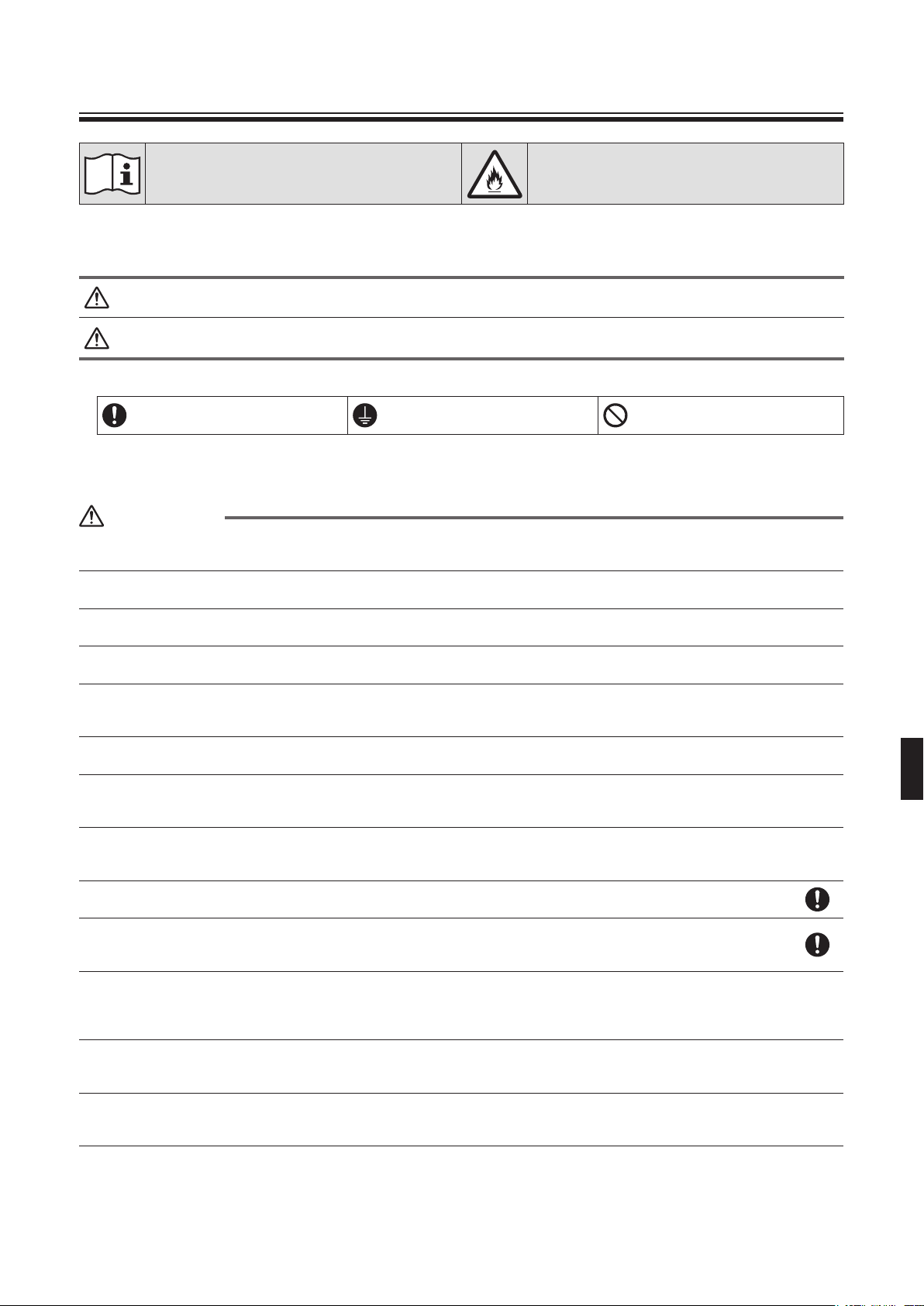
• Meaning of WARNING and CAUTION notices
WARNING ...................
CAUTION.....................
• The safety marks shown in this manual have the following meanings:
Be sure to follow the instructions.
• After completing installation, conduct a trial operation to check for faults and explain to the customer how to operate the air conditioner
and take care of it with the aid of the operation manual.
Failure to follow these instructions properly may result in personal injury or loss of life.
Failure to observe these instructions properly may result in property damage or personal injury,
which may be serious depending on the circumstances.
Be sure to establish an earth
connection.
This appliance is fi lled with R32.
Never attempt.
WARNING
• Ask your dealer or qualifi ed personnel to carry out installation work.
Do not attempt to install the air conditioner yourself. Improper installation may result in water leakage, electric shocks or fi re.
• Install the air conditioner in accordance with the instructions in this installation manual.
Improper installation may result in water leakage, electric shocks or fi re.
• Be sure to use only the specifi ed accessories and parts for installation work.
Failure to use the specifi ed parts may result in the unit falling, water leakage, electric shocks or fi re.
• Install the air conditioner on a foundation strong enough to withstand the weight of the unit.
A foundation of insuffi cient strength may result in the equipment falling and causing injury.
• Electrical work must be performed in accordance with relevant local and national regulations and with instructions in
this installation manual. Be sure to use a dedicated power supply circuit only.
Insuffi ciency of power circuit capacity and improper workmanship may result in electric shocks or fi re.
• Use a cable of suitable length.
Do not use tapped wires or an extension lead, as this may cause overheating, electric shocks or fi re.
• Make sure that all wiring is secured, the specifi ed wires are used, and that there is no strain on the terminal
connections or wires.
Improper connections or securing of wires may result in abnormal heat build-up or fi re.
• When wiring the power supply and connecting the wiring between the indoor and outdoor units, position the wires so
that the control box lid can be securely fastened.
Improper positioning of the control box lid may result in electric shocks, fi re or over heating terminals.
• If refrigerant gas leaks during installation, ventilate the area immediately.
Toxic gas may be produced if the refrigerant comes into contact with fi re.
• After completing installation, check for refrigerant gas leakage.
Toxic gas may be produced if the refrigerant gas leaks into the room and comes into contact with a source of fi re, such as a fan
heater, stove or cooker.
• When installing or relocating the air conditioner, be sure to bleed the refrigerant circuit to ensure it is free of air, and
use only the specifi ed refrigerant (R32).
The presence of air or other foreign matter in the refrigerant circuit causes abnormal pressure rise, which may result in
equipment damage and even injury.
• During installation, attach the refrigerant piping securely before running the compressor.
If the refrigerant pipes are not attached and the stop valve is open when the compressor is run, air will be sucked in, causing
abnormal pressure in the refrigeration cycle, which may result in equipment damage and even injury.
• During pump-down, stop the compressor before removing the refrigerant piping.
If the compressor is still running and the stop valve is open during pump-down, air will be sucked in when the refrigerant piping
is removed, causing abnormal pressure in the refrigeration cycle, which may result in equipment damage and even injury.
2
Safety Precautions
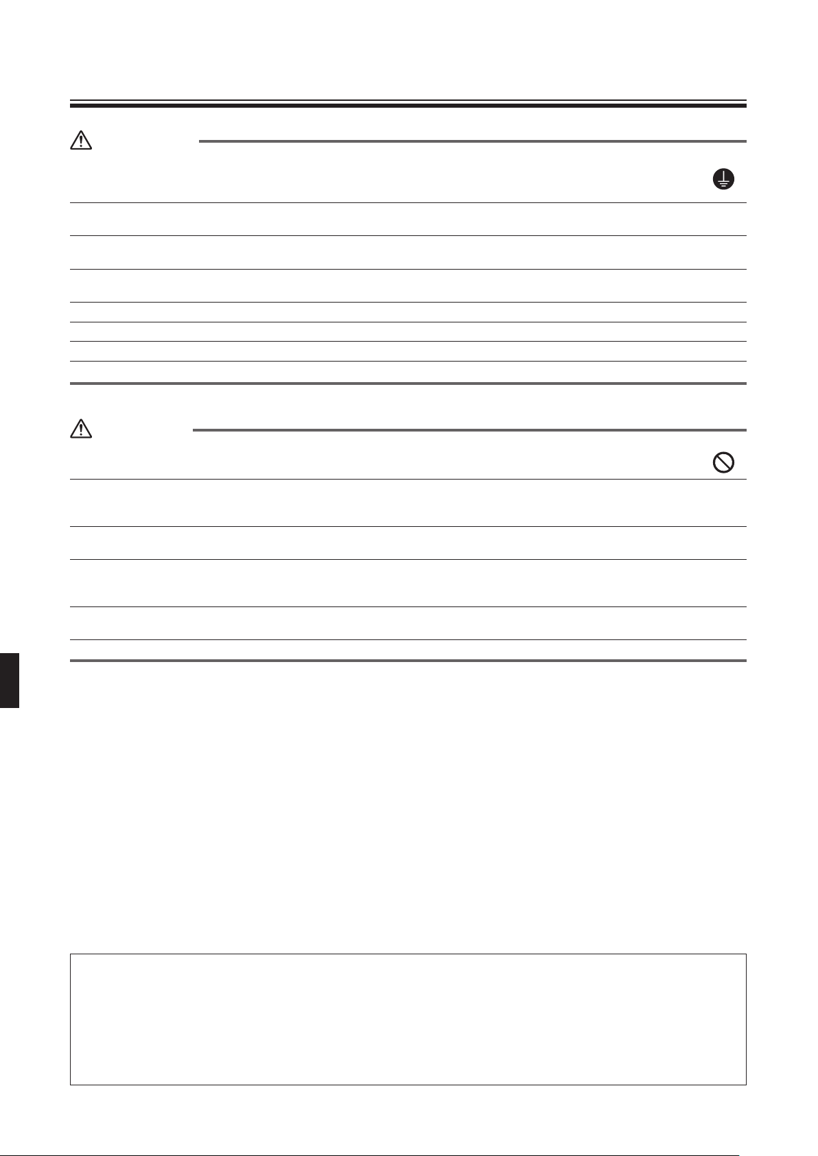
WARNING
• Be sure to earth the air conditioner.
Do not earth the unit to a utility pipe, lightning conductor or telephone earth lead. Imperfect earthing may result in electric
shocks.
• Be sure to install an earth leakage circuit breaker.
Failure to install an earth leakage circuit breaker may result in electric shocks or fi re.
• Do not use means to accelerate the defrosting process or to clean, other than those recommended by the
manufacturer.
• The appliance must be stored in a room without continuously operating ignition sources (for example: open fl ames,
an operating gas appliance or an operating electric heater).
• Do not pierce or burn.
• Be aware that refrigerants may not contain an odour.
2
• The appliance must be installed, operated and stored in a room with a fl oor area larger than 1.8m
• Comply with national gas regulations.
CAUTION
• Do not install the air conditioner at any place where there is a danger of fl ammable gas leakage.
In the event of a gas leakage, build-up of gas near the air conditioner may cause a fi re to break out.
• While following the instructions in this installation manual, install drain piping to ensure proper drainage and insulate
piping to prevent condensation.
Improper drain piping may result in indoor water leakage and property damage.
• Tighten the fl are nut according to the specifi ed method such as with a torque wrench.
If the fl are nut is too tight, it may crack after prolonged use, causing refrigerant leakage.
• Take adequate steps to prevent the outdoor unit being used as a shelter by small animals.
Small animals making contact with electrical parts can cause malfunctions, smoke or fi re. Please instruct the customer to keep
the area around the unit clean.
• The temperature of refrigerant circuit will be high, please keep the inter-unit wire away from copper pipes that are not
thermally insulated.
• Only qualifi ed personnel can handle, fi ll, purge and dispose of the refrigerant.
.
N002
Important information regarding the refrigerant used
This product contains fl uorinated greenhouse gases covered by the Kyoto Protocol. Do not vent gases into the atmosphere.
Refrigerant type: R32
(1)
GWP
value: 550 *
(1)
GWP = global warming potential
The refrigerant quantity is indicated on the unit name plate.
* This value is based on F gas regulation (824/2006).
3
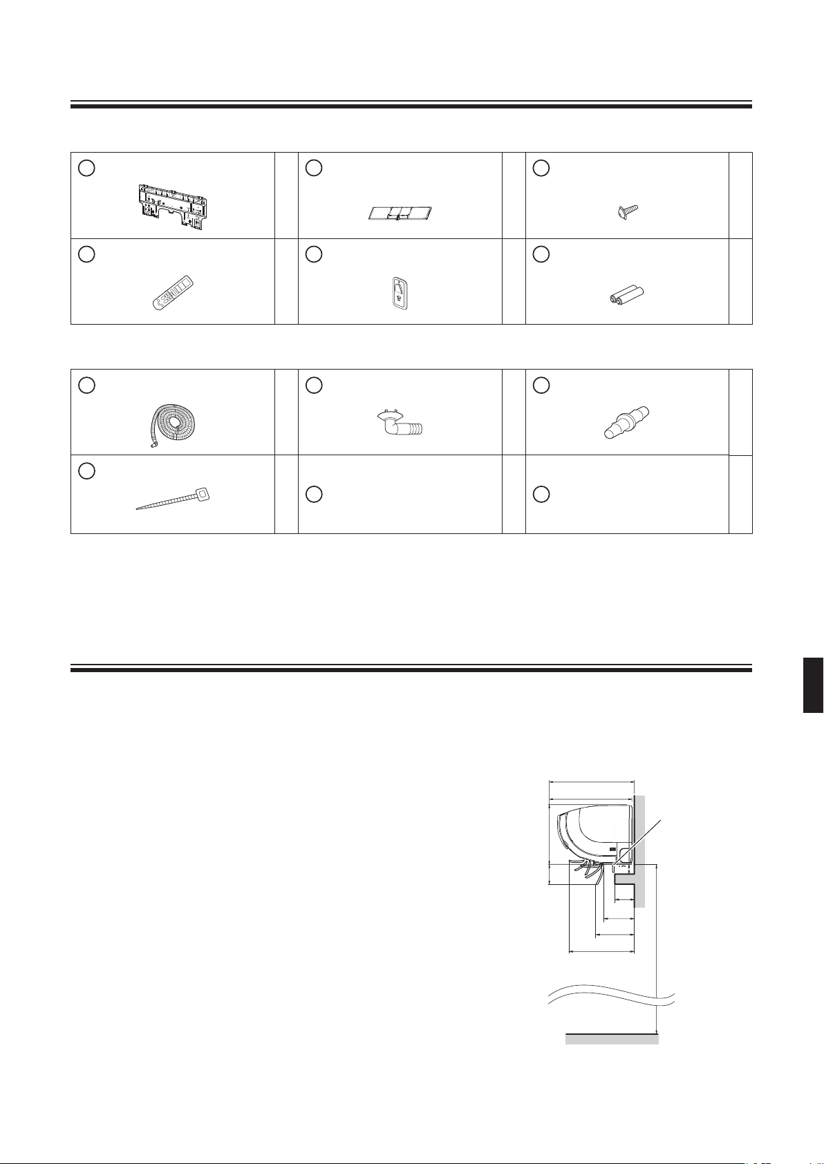
Accessories
Indoor unit
Mounting plate
A
Wireless remote controller
D
B
Photocatalytic air-purifying and
1
1
deodorising fi lter
Remote controller holder
E
C
Indoor unit fi xing screws
1
1
(M4 × 12L)
Dry batteries AA.LR6 (alkaline)
F
Outdoor unit
Humidifying hose (8m)
G
1
Binding bands
K
3
• The standard humidifying hose is 8m.
• The extension hose (option) is 2m (KPMH974A402).
• An humidifying hose of 10m (KPMH974A42) is also available as an option to replace the standard one (8m).
Drain socket
H
Operation manual 1
L
Joint
J
1
Installation manual
M
3
2
1
1
Choosing an Installation Site
Before choosing the installation site, obtain user approval.
1. Indoor unit
• The indoor unit should be sited in a place where:
1) the restrictions on installation specifi ed in “Indoor/Outdoor Unit
Installation Drawings” on page 6 are met,
2) both air inlet and outlet are free of obstructions,
3) the unit is not in the path of direct sunlight,
4) the unit is away from the source of heat or steam,
5) there is no source of machine oil vapour (this may shorten indoor unit life),
6) cool/warm air is circulated throughout the room,
7) the unit is away from electronic ignition type fl uorescent lamps (inverter or
rapid start type) as they may shorten the remote control range,
8) the unit is at least 1m away from any television or radio set (unit may cause
interference with the picture or sound),
9) space allows for the moving range of the fl ap in operation above curtain
rails or other objects,
If (**) is 70mm or more, allow for 15mm of space from the indoor unit.
If it is less than 15mm, this can affect the opening and closing of the
shutter (bottom air inlet).
10) a height of 2.5m or more is allowed for installation,
11) no laundry equipment is located nearby.
Including the mounting plate *
372*
370
295
86
15
(**)
150*
179*
328*
2500 or more
Shutter
(Bottom air inlet)
unit : mm
4
Choosing an Installation Site
2. Wireless remote controller (When mounting on a wall etc.)
• Turn on all the fl uorescent lamps in the room, if any, and fi nd the site where remote control signals are properly received by the
indoor unit (within 7m).
• Select a place where the remote controller is not hit by direct sunlight. (Selecting a place where direct sunlight hits the remote
controller makes it diffi cult for the remote controller to receive the signal from the indoor unit.)
3. Outdoor unit
• The outdoor unit should be sited in a place where:
1) the restrictions on installation specifi ed in “Indoor/Outdoor Unit Installation Drawings” on page 6 are met,
2) the ground is solid enough to bear the weight and vibration of the unit and where the operating sound will not be amplifi ed,
3) the hot air discharged from the unit or the operating sound will not cause a nuisance to the neighbors of the user,
4) there is no bedroom or the like nearby, so that the operating sound will cause no trouble,
5) there are suffi cient spaces for carrying the unit into and out of the site,
6) both air inlet and outlet have clear paths of air (they should be free of snow in snowy districts),
7) there is no fear of infl ammable gas leakage in a nearby place,
8) units, power cords and inter-unit wires at least 3m away from television and radio sets (This is to prevent interference to images
and sounds. Noises may be heard even if they are more than 3m away depending on radio wave conditions),
9) the unit is not directly exposed to salt, sulfi dized gases, or machine oil vapour (they may shorten outdoor unit life),
10) nothing which must be kept away from moisture is under the unit since drain fl ows out of the outdoor unit,
11) the air is clean, and there are no sources of unpleasant odours close by.
NOTE
Cannot be installed hanging from ceiling or stacked.
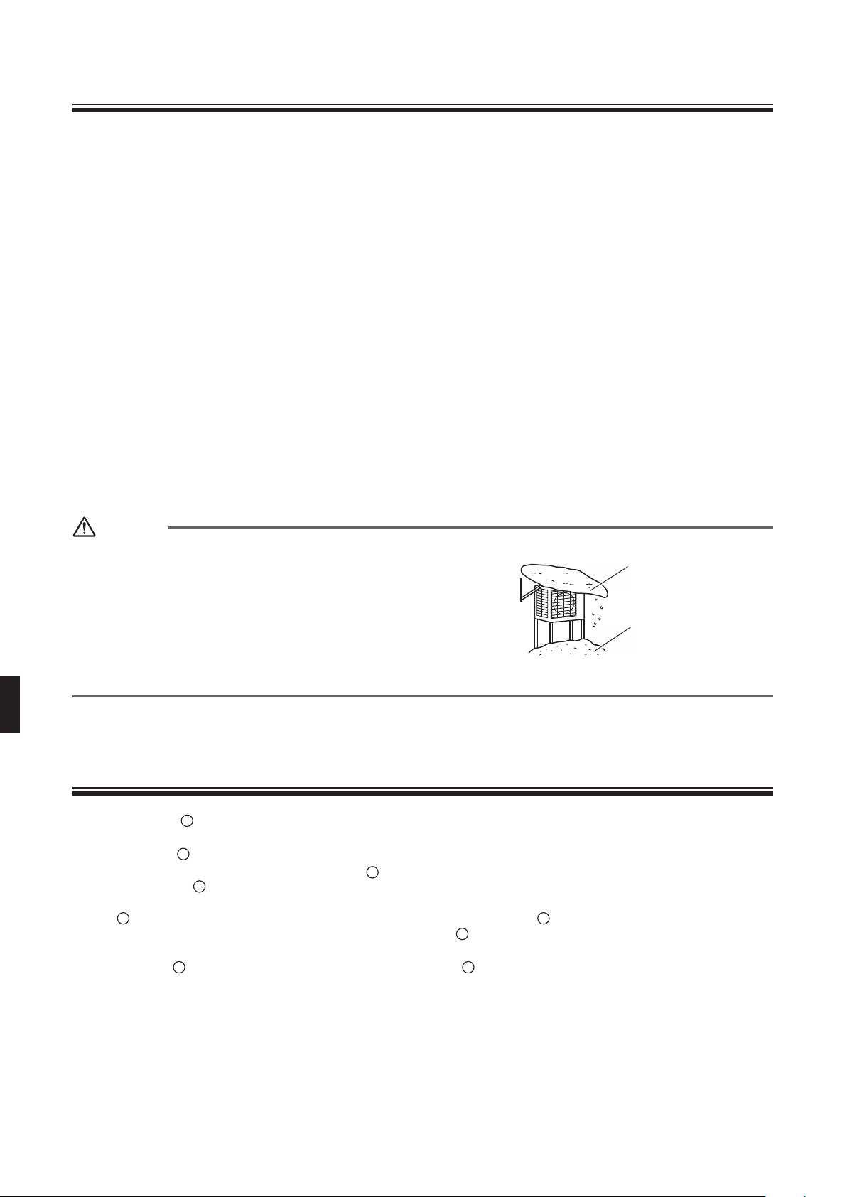
CAUTION
When operating the air conditioner in a low outdoor ambient temperature, be
sure to follow the instructions described below.
• To prevent exposure to wind, install the outdoor unit with its suction side
facing the wall.
• Never install the outdoor unit at a site where the suction side may be
exposed directly to wind.
• To prevent exposure to wind, it is recommended to install a baffl e plate on
the air discharge side of the outdoor unit.
• In heavy snowfall areas, select an installation site where the snow will not
affect the unit.
• Construct a large canopy.
• Construct a pedestal.
Install the unit high enough off
the ground to prevent burying
in snow.
Precautions for humidifying hose installation work
• When embedding G humidifying hose:
Cannot be installed to the existing embedded piping. Embedding work is separately necessary.
• The length of the
1) Use an extension hose (option) when extending the
2) The length of the G humidifying hose needs to be set to ensure humidifying capacity. Cut off any excess hose.
Use the remote controller to set the hose length. (Refer to “9. Setting the humidifying hose length” on page 16.)
• If the
• When laying the
G
humidifying hose needs to be cut to be laid, cut it, lay it, and connect it using the J joint included with the outdoor unit or an
elbow (fi eld supply). When doing this, wrap it to prevent air leaks with the K binding band included with the outdoor unit.
(Refer to “4-2 Connecting the cut humidifying hoses” on page 8.)
anything else from entering it until it is connected to the indoor unit and outdoor unit ducts.
G
humidifying hose is marked on the hose packing material.
G
humidifying hose.
G
humidifying hose inside the wall, block the ends of the G humidifying hose with tape or the like to prevent water or
5
 Loading...