


Installation, Operation and Maintenance Manual
D–EIMAC01208-16EN
Air Cooled Chiller Multiscroll
EWAQ~G-
SS (Standard Efficiency - Standard Noise)
SR (Standard Efficiency - Reduced Noise)
XS (High Efficiency - Standard Noise)
XR (High Efficiency - Reduced Noise)
Refrigerant: R410A
Original Instructions
D-EIMAC01208-16EN - 1/24

Table of contents
Description ................................................................................................................................................................. 3
General Information .................................................................................................................................................. 3
Receiving the unit ..................................................................................................................................................... 3
Storage ...................................................................................................................................................................... 3
Operation ................................................................................................................................................................... 3
Figure 1 - Description of the labels applied to the electrics panel ....................................................................... 4
Figure 2 - Operating limits ....................................................................................................................................... 4
Safety ......................................................................................................................................................................... 7
Positioning and assembly ........................................................................................................................................ 8
Figure 3 - Distances to be complied with: .............................................................................................................. 8
Noise .......................................................................................................................................................................... 8
Handling and lifting .................................................................................................................................................. 8
Figure 4 – Lifting the unit ......................................................................................................................................... 9
Sound protection ...................................................................................................................................................... 9
Hydraulic circuit for connection to the unit ............................................................................................................ 9
Pipe insulation ........................................................................................................................................................ 10
Installing the flow switch ....................................................................................................................................... 10
Preparing and checking the water circuit connection ......................................................................................... 10
Water treatment ...................................................................................................................................................... 11
Water flow and volume ........................................................................................................................................... 11
Anti-freeze protection for evaporators and recovery exchangers ..................................................................... 12
Electrical system General specifications ............................................................................................................. 12
Wiring at the installation site ................................................................................................................................. 13
Electric circuit and wiring requirements............................................................................................................... 13
Connection of the unit power supply .................................................................................................................... 13
Interconnecting wires ............................................................................................................................................. 13
Before start-up ........................................................................................................................................................ 13
Open the isolation and/or shut off valves............................................................................................................. 14
User responsibilities .............................................................................................................................................. 14
Periodical maintenance .......................................................................................................................................... 14
Service and limited guarantee ............................................................................................................................... 14
Mandatory periodical checks and start-up of Groups (units) ............................................................................. 15
Bleeding refrigerant gas from the safety valve .................................................................................................... 15
Important information regarding the refrigerant used ........................................................................................ 16
Product lifespan ...................................................................................................................................................... 16
Disposal ................................................................................................................................................................... 18
Figure 5 – Unit wiring in installation site .............................................................................................................. 19
D-EIMAC01208-16EN - 2/24
Thank you for purchasing this chiller
This manual is an important support document for qualified personnel but it is not intended to replace such personnel.
READ THIS MANUAL CAREFULLY BEFORE INSTALLING AND
STARTING UP THE UNIT.
IMPROPER INSTALLATION COULD RESULT IN ELECTRIC SHOCK,
SHORT-CIRCUIT, COOLANT LEAKS, FIRE OR OTHER DAMAGE TO
EQUIPMENT OR INJURY.
THE UNIT MUST BE INSTALLED BY A PROFESSIONAL
OPERATOR/TECHNICIAN.
UNIT STARTUP MUST BE PERFORMED BY AUTHORISED,
TRAINED PERSONNEL.
ALL ACTIVITIES MUST BE CARRIED OUT IN ACCORDANCE WITH
LOCAL LAWS AND REGULATIONS.
IF THE INSTRUCTIONS IN THIS MANUAL ARE NOT ABSOLUTELY
CLEAR, DO NOT INSTALL AND/OR OR START UP THE UNIT.
IF CASE OF DOUBT CONTACT THE MANUFACTURER'S
REPRESENTATIVE FOR ADVICE AND INFORMATION.
Description
The unit purchased is a Water Chiller that is designed
to cool water (or a water-glycol mixture) within certain
limits which will be listed below. The unit operates
based on the compression, condensation and
evaporation of vapour as per the Carnot cycle and
consists mainly of the following components:
- One or more scroll compressors which increase the
pressure of the refrigerant gas from evaporation
pressure to condensation pressure.
- A condenser where the refrigerant gas condenses
under high pressure and transfers heat to the
water.
- An expansion valve which allows the pressure of
condensed liquid refrigerant to be reduced from
condensation pressure to evaporation pressure.
- An evaporator, where the low pressure liquid
refrigerant evaporates and chills the water.
General Information
All the units are delivered with wiring diagrams,
certified drawings, ID plate and DoC (Declaration of
Conformity). These documents list all the technical
data of the unit acquired and CONSTITUTE AN
INTEGRAL AND ESSENTIAL PART OF THIS MANUAL.
In the event of any discrepancy between this manual
and the appliance documents, please refer to the
documents that come supplied with the unit. In case of
doubt, contact the manufacturer's representative.
The aim of this manual is to make sure that the installer
and the qualified operator can properly commission,
operate and maintain the unit without creating any risk
to people, animals or things.
Receiving the unit
The unit must be inspected for any possible damage
immediately upon reaching final place of installation. All
components described in the delivery note must be
inspected and checked.
Should there be evidence of damage, do not remove
the damaged components and immediately report the
extent and type of damage both to the transportation
company, asking them to inspect it, and the
manufacturer's representative, sending if possible
photos which may be useful in identifying those
responsible.
Damage must not be repaired before the inspection of
the transportation company representative and the
manufacturer's representative.
Before installing the unit, check that the model and
power supply voltage shown on the nameplate are
correct. The manufacturer will not accept responsibility
for any damage following acceptance of the unit.
Storage
The unit must be protected from dust, rain, constant
exposure to the sun and possible corrosive agents and
rodents when being stored outside before installation.
Even though it is covered by a heat-shrinking plastic
sheet, this is not intended for long-term storage and
must be removed as soon as the unit is unloaded. The
unit must be protected by tarpaulins or suchlike which
are more suitable for the long term.
Storage conditions must be within the following limits:
Minimum ambient temperature: -20 °C
Maximum ambient temperature: +42 °C
Maximum relative humidity: 95% without condensation.
If the unit is stored at a temperature below the minimum
ambient temperature, the components may be
damaged, while at a temperature above the maximum
ambient temperature, the safety valves could open and
discharge the refrigerant into the atmosphere.
Operation
Operation outside any of the above-mentioned limits
may damage the unit.
In case of doubt, contact manufacturer's representative.
.
D-EIMAC01208-16EN - 3/24

Figure 1 - Description of the labels applied to the electrics panel
1 – Slack electrical cable warning
5 – Type of gas
2 – Hazardous voltage warning
6 – Non flammable gas symbol
3 – Electrical hazard symbol
7 – Unit ID plate information
4 – Manufacturer’s logo
8 – Lifting instructions
Ambient temperature
(°C)
Identification of labels
*With the exception of the unit ID plate, which is always in the same position, the other plates may be in different
positions depending on the model and options on the unit.
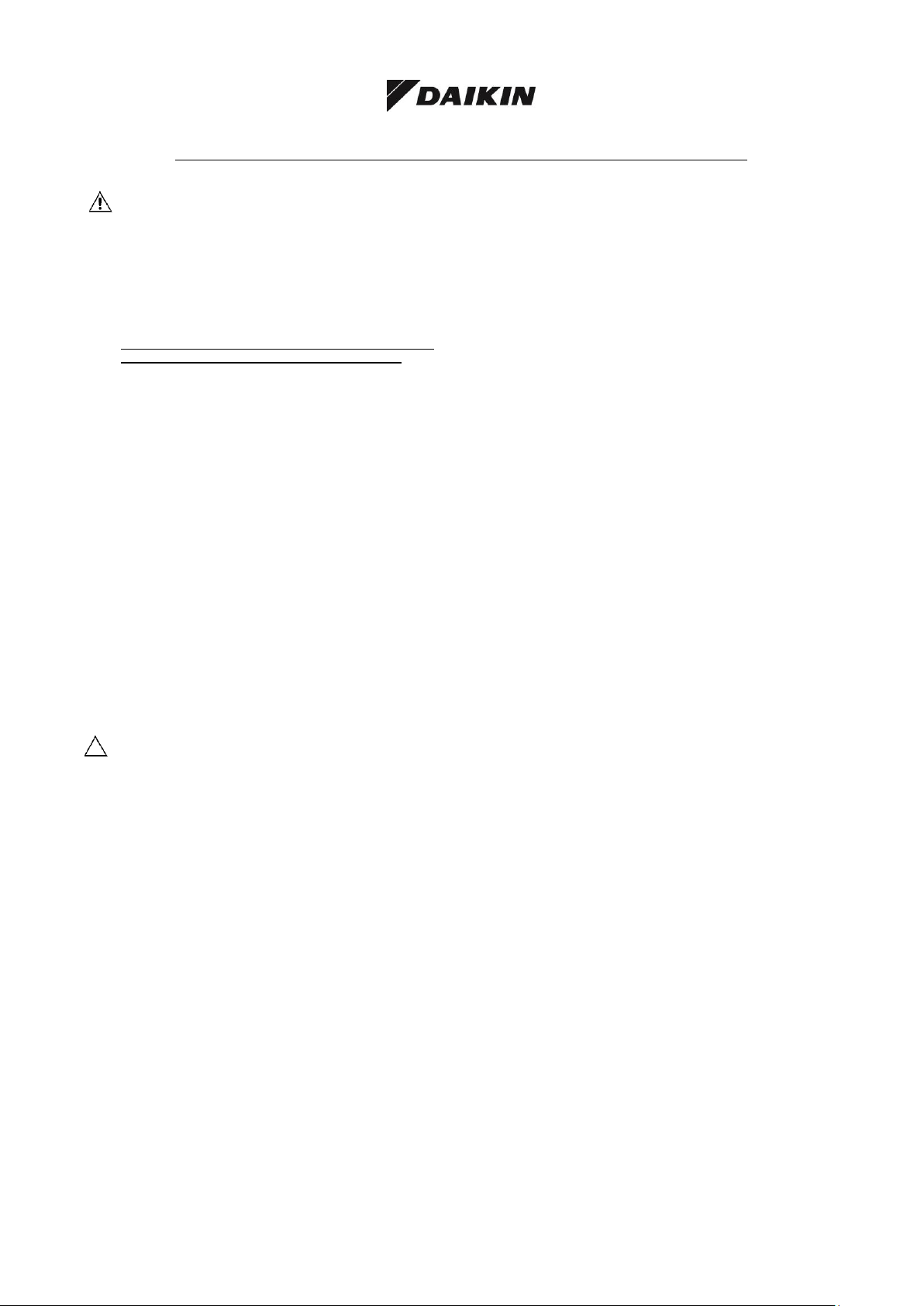
Figure 2 - Operating limits
EWAQ G SS (Standard efficiency– Standard noise)
Water temperature at outlet (°C)
D-EIMAC01208-16EN - 4/24
Ambient temperature
(°C)
Ambient temperature
(°C)
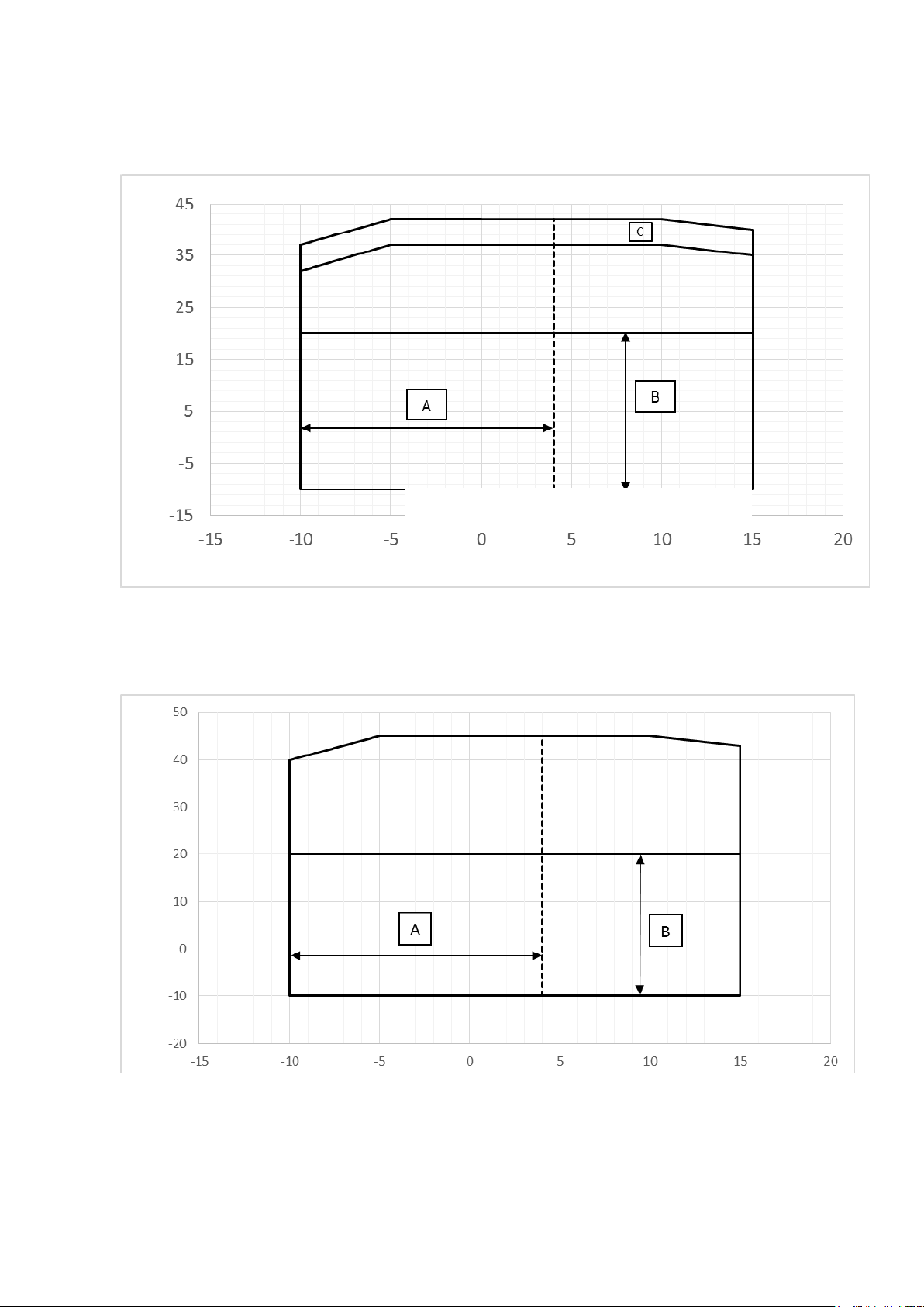
EWAQ G SR (Standard efficiency – Reduced noise)
Water temperature at outlet (°C)
EWAQ G XS (High efficiency – Standard noise)
Water temperature at outlet (°C)
D-EIMAC01208-16EN - 5/24
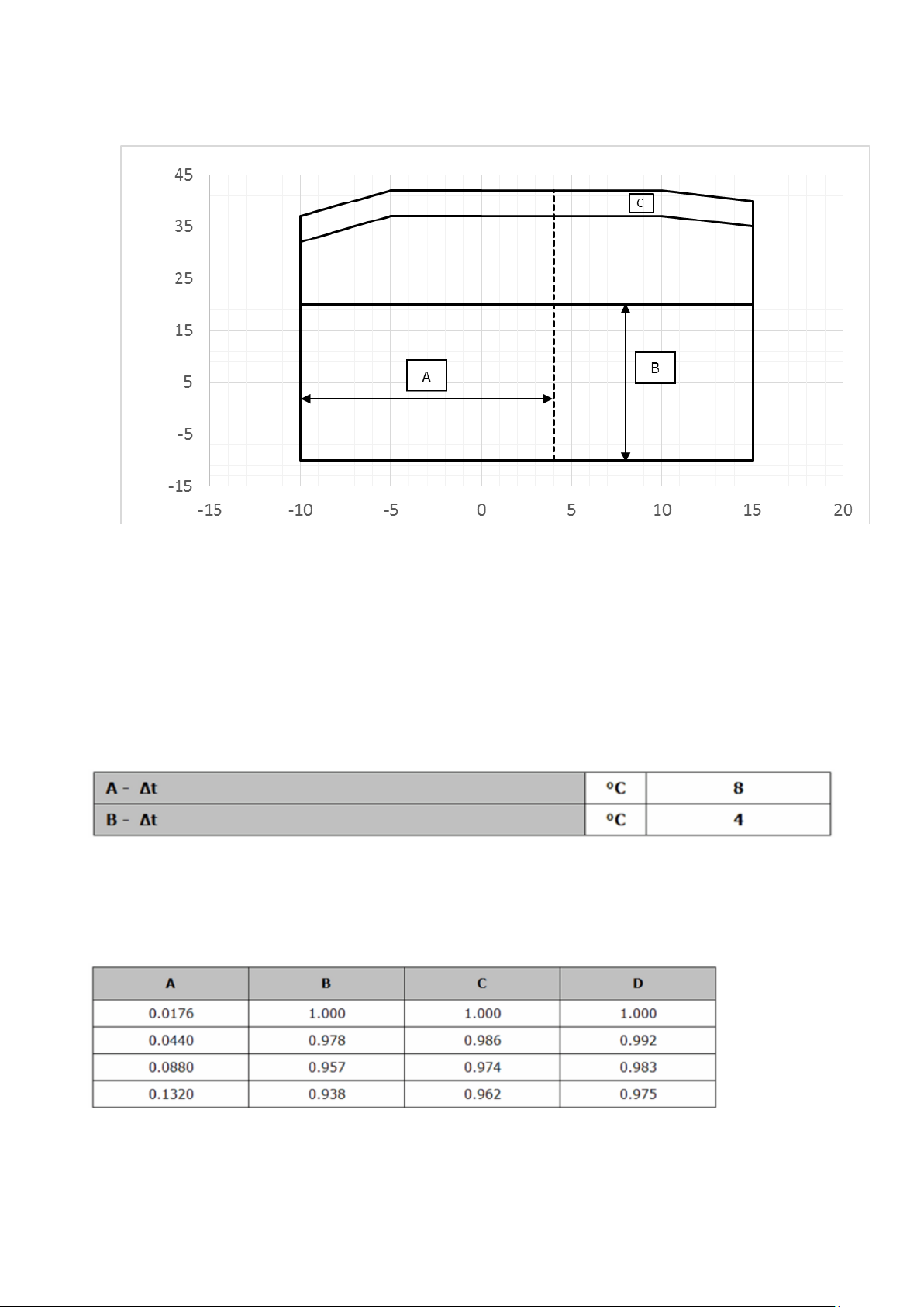
EWAQ G XR (High efficiency - Reduced noise)
Ambient temperature
(°C)
Water temperature at outlet (°C)
Notes
The diagram shows the guide lines for the range of operating limits. Refer to the Chiller Selection Software (CSS) for the
true operating limits under working conditions for each model.
Legend
Ambient temperature (°C) = Air temperature at condenser inlet (°C)
Water temperature at outlet (°C) = Water temperature at evaporator outlet (°C)
A = Operating with glycol
B = Operating with fan speed mode selected
C = Operating at maximum fan speed
Table 1 - Evaporator – Difference in temperature Δt at Minimum and Maximum
Legend
A = Δt Maximum difference in evaporator water temperature
B = Δt Minimum difference in evaporator water temperature
Table 2 – Evaporator – Scaling factor
Legend
A = Scaling factor (m² °C / kW)
B = Refrigeration capacity correction factor
C = Power consumption correction factor
D = EER correction factor
D-EIMAC01208-16EN - 6/24
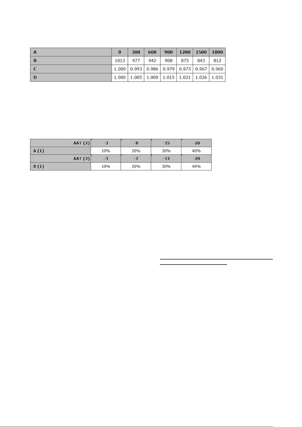
Table 3 - Air heat exchanger - Correction factor at altitude
Legend
A = Altitude above sea level (m)
B = Atmospheric pressure (mbar)
C = Refrigeration capacity correction factor
D = Power consumption correction factor
- The maximum operating altitude is 2000 metres above sea level
- If the unit is to be installed at an altitude of between 1000 and 2000 metres above sea level, contact manufacturer.
Table 4 – Minimum percentage of glycol for low air ambient temperature
Legend
AAT = Ambient Air Temperature (°C) (2)
A = Ethylene glycol (%) (1)
B = Propylene glycol (%) (1)
(1) Minimum percentage of glycol to prevent the water circuit from freezing at the indicated ambient air temperature.
(2) Ambient air temperature which exceeds unit operating limits.
Water circuits must also be protected in winter even if the unit is not being used.
Legend
A = External Static Pressure (Pa)
B = Refrigeration capacity correction factor (kW)
C = Power consumption correction factor (kW)
D = Reduction of maximum temperature of the air which passes through the condenser
Safety
The unit must be firmly secured to the ground.
The following instructions must be followed:
Never access electrical components without having
first closed the main switch and switched off the
power supply.
Never access electrical components without some
form of insulation. Never access electrical
components if water and/or moisture are present.
Always disconnect the power supply by closing the
main switch before carrying out any work on the
cooling fans and/or compressors. Failure to do so
may result in serious injury.
Sharp edges can cause injuries. Avoid direct
contact with components and wear suitable PPE.
Do not introduce solid objects into water pipes.
A mechanical filter must be fitted to the water pipe
connected to the heat exchanger inlet.
The unit is supplied with high pressure switches
and/or safety valves, that are installed on both the
high-pressure and low-pressure sides of the
refrigerant circuit: pay attention.
It is absolutely forbidden to remove any protection
system covering moving parts.
In the event of a sudden stop, follow the instructions in
the Control Panel Instruction Manual which is part of
the documentation supplied with the unit.
We strongly recommend that installation and
maintenance operations are be performed alone but
with other people present.
In the event of an accident or problem:
Keep calm
Press the alarm button, if present or close the main
switch
Move the injured person to a warm place far from
the unit and in place him or her in the recovery
position
Immediately contact any emergency personnel in
the building or the call the Emergency Services
Wait until emergency personnel arrive and do not
leave the injured person alone
Give all necessary information to the emergency
personnel.
D-EIMAC01208-16EN - 7/24
Positioning and assembly
The unit must be installed on a solid, perfectly level
base. For earthing purposes, a solid cement base, that
is wider than the unit, must be made. This base must be
able to support the weight of the unit.
Anti-vibration supports must be installed between the
frame of the unit and the cement base of the steel
beams; for such installation follow the dimensional
drawing supplied with the unit.
The frame of theunit must be perfectly levelled during
installation, if necessary using shims to be inserted
under the the anti-vibration supports.
Before first start-up, the installation must be confirmed
as being level and horizontal using a laser level or
another suitable instrument.
Any error in the level and horizontal position must not
be greater than 5 mm per unit up to 7 metres and
10mm per unit over 7 metres.
If the unit is installed in places that are easily accessible
to people and animals, we recommend that protection
grates are fitted all round to prevent access. To ensure
optimal performance in installation site, the following
precautions and instructions must be respected:
- Make sure that there is a strong, solid foundation to
reduce noise and vibrations.
- Avoid installing the unit in areas that could be
dangerous during maintenance operations, such as
platforms without handrails, guide rails or in areas that
fail to comply with requirements as regards free space
around the unit.
The installer is responsible for calculating the best
position for the unit.
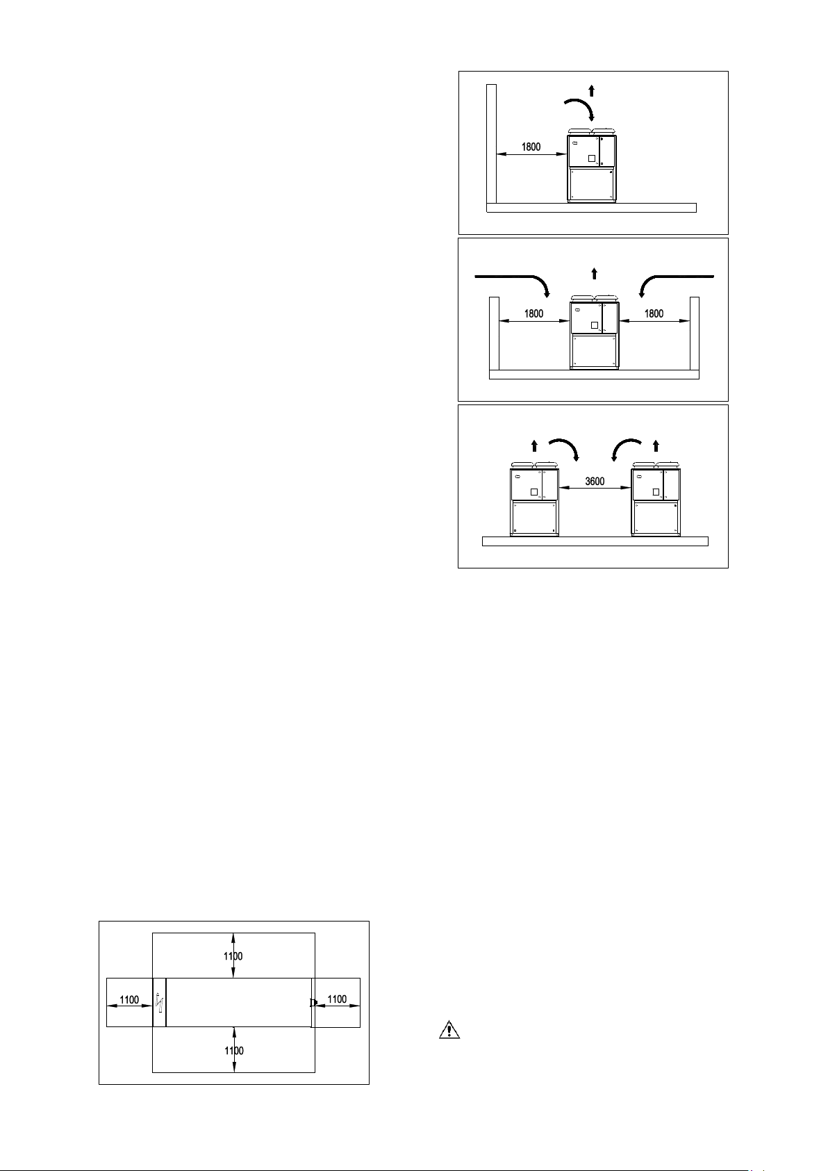
It is vital that all minimum distances for all units are
complied with to ensure there is adequate ventilation for
the condenser racks.
When deciding where to position the unit and to ensure
proper airflow, the following factors must be taken into
consideration:
avoid the recirculation of hot air
avoid insufficient air supply for the air cooling
condenser.
Both these conditions can cause an increase in
condenser pressure which can lead to poor energy
efficiency and refrigerating capacity.
If two or more units are positioned alongside each
other, we recommend leaving a space of at least 3600
millimetres between condenser racks. Each side of the
unit must be accessible for post-installation
maintenance work.
It is therefore vital that the minimum access distances in
front of the electrical panel are complied with: 1500 mm.
The manufacturer cannot be expected to consider all
these factors. In the unit design stage, we therefore
recommend that you consult an authorised
manufacturer representative for further solutions.
Figure 3 - Distances to be complied with:
Noise
The noise generated by the unit is mainly due to the
rotation of compressors.
The noise level for each model size is listed in sales
documentation.
If the unit is correctly installed, operated and
maintained, noise emission levels do not require any
special protective devices to operate continuously close
to the unit without any risk.
In case of installation with special noise requirements it
may be necessary to install additional noise softening
devices.
Handling and lifting
The unit must be lifted with the utmost care and
attention, following the lifting instructions shown on the
label applied to the electric panel. Lift the unit very
slowly, keeping it perfectly level.
Avoid bumping and/or shaking the unit during handling
and loading/unloading operations from the
transportation vehicle, push or pull the unit only using
the base frame. Secure the unit inside the truck to
prevent it from moving and causing damage. Do not
allow any part of the unit to fall during
loading/unloading.
All units have lifting points. Only these points may be
used for lifting the unit, as shown in the following figure.
Handling and lifting with a fork lift is the only alternative
method.
Both the lifting ropes and the spacing bars must
be strong enough to support the unit safely. Check
the weight of the unit on its name plate, because
D-EIMAC01208-16EN - 8/24
 Loading...