

Daewoo KOC-872 Service Manual
1
PRECA UTIONS T O BE OBSERVED BEFORE AND
DURING SER VICING T O AVOID POSSIBLE
EXPOSURE T O EXCESSIVE MICROW AVE ENERGY
(a)Do not operate or allow the oven to be operated with the door open.
(b)Make the following safety checks on all ovens to be serviced before activating the magnetron or other micro-
wave source, and make repairs as necessary: (1) Interlock operation, (2) proper door closing, (3) seal and
sealing surfaces (arcing, wear, and other damage), (4) damage to or loosening of hinges and latches, (5)
evidence of dropping or abuse.
(c) Before turning on microwave power for any service test or inspection within the microwave generating com-
partments, check the magnetron, wave guide or transmission line, and cavity for proper alignment, integrity,
and connections.
(d)Any defective or misadjusted components in the interlock, monitor, door seal and microwave generation and
transmission systems shall be repaired, replaced, or adjusted by procedures described in this manual before
the oven is released to the owner.
(e) A microwave leakage check to verify compliance with the Federal Performance Standard should be
performed on each oven prior to release to the owner.
TABLE OF CONTENTS
PROPER USE AND SERVICE PRECAUTIONS 2
SPECIFICATIONS
3
NAMES AND FUNCTION OF PARTS
4
CONTROL PANEL
5
OPERATION
6
INTERLOCK MECHANISM FUNCTIONS AND ADJUSTMENTS
7
PRECAUTIONS FOR DISASSEMBLY AND REPAIR
9
DISASSEMBLY AND ASSEMBLY
10
TROUBLE SHOOTING GUIDE
18
MEASUREMENT
24
COMPONENT TEST PROCEDURE
26
WIRING DIAGRAM
27
SCHEMATIC DIAGRAM
28
EXPLODED VIEWS AND PARTS LIST
31
PRINTED WIRING BOARD
32
P.C.B. BOARD DIAGRAM
37
P.C.B. CIRCUIT DIAGRAM
39
P.C.B. ASS’Y PARTS LIST
40
2
PROPER USE AND SERVICE PRECA UTIONS
1. For Safe Operation
Damage that allows the microwave energy (that cooks or heats the food) to escape will result in poor cooking and may
cause serious bodily injury to the operator.
IF ANY OF THE FOLLOWING CONDITIONS EXIST, OPERATOR MUST NOT USE THE APPLIANCE.
(Only a trained service personnel should make repairs.)
1) A broken door hinge.
2) A broken door viewing screen.
3) A broken front panel, oven cavity.
4) A loosened door lock.
5) A broken door lock.
The door gasket plate and oven cavity surface should be kept clean.
No grease, soil or spatter should be allowed to build up on these surfaces or inside the oven.
DO NOT ATTEMPT TO OPERATE THIS APPLIANCE WITH THE DOOR OPEN. The microwave oven has concealed
switches to make sure the power is turned off when the door is opened. Do not attempt to defeat them.
DO NOT ATTEMPT TO SERVICE THIS APPLIANCE UNTIL YOU HAVE READ THIS SERVICE MANUAL.
2. For Safe Service Procedures.
1) This microwave oven weight 17.6kg (38.9 lbs.) and must be placed on a horizontal base strong enough to support
this weight.
2) The oven should be placed as far from high temperature source and vapour as possible.
3) The power supply cord is about 1.1m (3.6ft) long. Earthing is required when connecting the power source.
4) Maximum power consumption of this oven is approximately 2.7Kw(230V). It is suggested that the unit is operated on
such power line (about 13 amperes) that can provide more power than this rating.
5) Object must not be placed on the top enclosure so as not to obstruct air flow for ventilation.
The wires in this mains lead coloured in accordance with the following code.
Green-and-yellow : Earth
Blue : Neutral
Brown : Live
As the colours of the wires in the mains lead of this appliance may not correspond with the coloured markings
identifying the terminals in your plug, proceed as follows:
The wire which is coloured green-and-yellow must be connected the the terminal in the plug which is marked with
the letter ‘E’ or by earth symbol or green-and-yellow.
The wire which is coloured blue must be connected to the terminal which is marked with the letter ‘N’ or coloured
black.
The wire which is coloured brown must be connected to the terminal which is marked with the letter ‘L’ or coloured
red.
WARNING : This appliance must be earthed.
NOTE : This oven is designed for counter-top use only.
IMPORTANT
3
POWER SUPPLY 230V ~ , 50Hz 240V~, 50Hz
POWER CONSUMPTION 1,500W 1,550W
MICROWAVE OUTPUT POWER 900 W (IEC 705) 900W(IEC 705)
FREQUENCY 2,450 MHZ 2,450MHz
GRILL POWER CONSUMPTION 1,250 W 1,300W
CONVECTION POWER CONSUMPTION 1,650 W 1,700W
COMBINATION HEATING POWER CONSUMPTION 2,700 W 2,750W
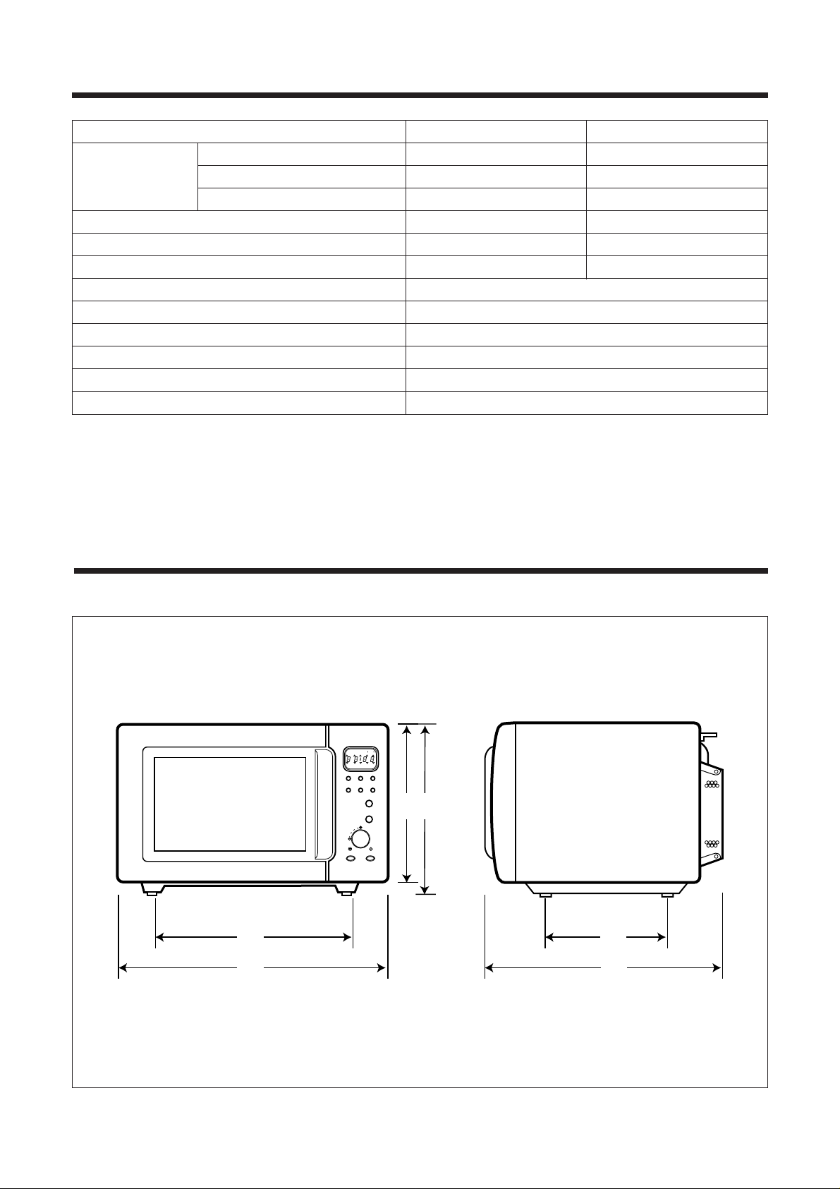
OUTSIDE DIMENSIONS (W X D X H) 501 (19.7) X398 (15.7) X 320 (12.6) mm (inch)
CAVITY DIMENSIONS (W X D X H) 310 (12.2) X 320 (12.6) X 229 (9.0) mm (inch)
NET WEIGHT 17.6 kg (38.9 Ibs.)
TIMER 60 minutes
SELECT FUNCTION Microwave/Grill /Convection /Combination
MICROWAVE POWER LEVEL 10 stages
* Specifications subject to change without notice.
332
294
320
501
210
398
GRILL COMBI TEMP
M/W DEFROST PIE
PROGRAM COOK
1. ROAST BEEF
2. ROAST PORK
3. ROAST CHICKEN
4. FISH FILLETS
5. VEGETABLE
SPEEDY COOK
STOP/CLEAR START
PROGRAM
COOK
KgTEMP
COOK
PIE
M/W GRILL COMBI
WEIGHT
DEFROST
TIME
Fig. 1 Front View Fig. 2 Side View
SPECIFICATIONS
EXTERNAL VIEWS
4
3 5 64
2
1 9 8
8
10
7
11
GRILL COMBI TEMP
M/W DEFROST PIE
PROGRAM COOK
1. ROAST BEEF
2. ROAST PORK
3. ROAST CHICKEN
4. FISH FILLETS
5. VEGETABLE
SPEEDY COOK
STOP/CLEAR START
PROGRAM
COOK
KgTEMP
COOK
PIE
M/W GRILL COMBI
WEIGHT
DEFROST
TIME
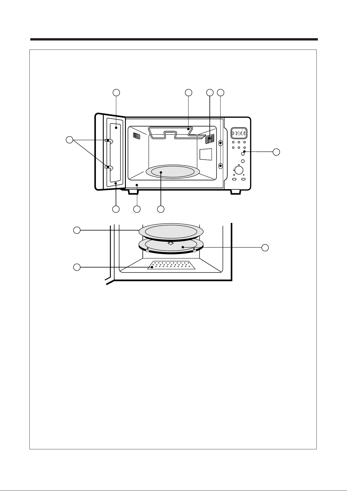
¤ DOOR SEALƒ¡
Door seal maintains the
microwave within the oven cavity and prevents
microwave leakage.
¤Ł DOOR HOOKƒ¡When door is closed, it will
automatically lock shut. If door is opened while
oven is operating, magnetron tube will immediately
stop operating.
¤Ø
DOOR SCREENƒ¡Allows viewing of food.
Microwave cannot pass through perforations in
screen.
¤Œ GRILL HEATER ƒ¡Turns on when grill and
simulta-neous cooking is selected.
¤º OVEN LAMP ƒ¡Automatically turns on during
oven operating.
¤ SAFETY INTERLOCK SYSTEM
¤ CONTROL PANEL
¤ TURNTABLE TRAYƒ¡Rotates during cooking
and ensure even distribution of Microwaves. It can
also be used as a cooking utensil.
¤ OVEN FRONT PLATE
¤ ROTATING BASE ƒ¡
This fits over the shaft in the
center of the oven’s cavity floor. This is to remain in
the oven for all cooking. It should only be removed
for cleaning.
¤æ UNDER HEATER
NAMES AND FUNCTION OF PARTS
5
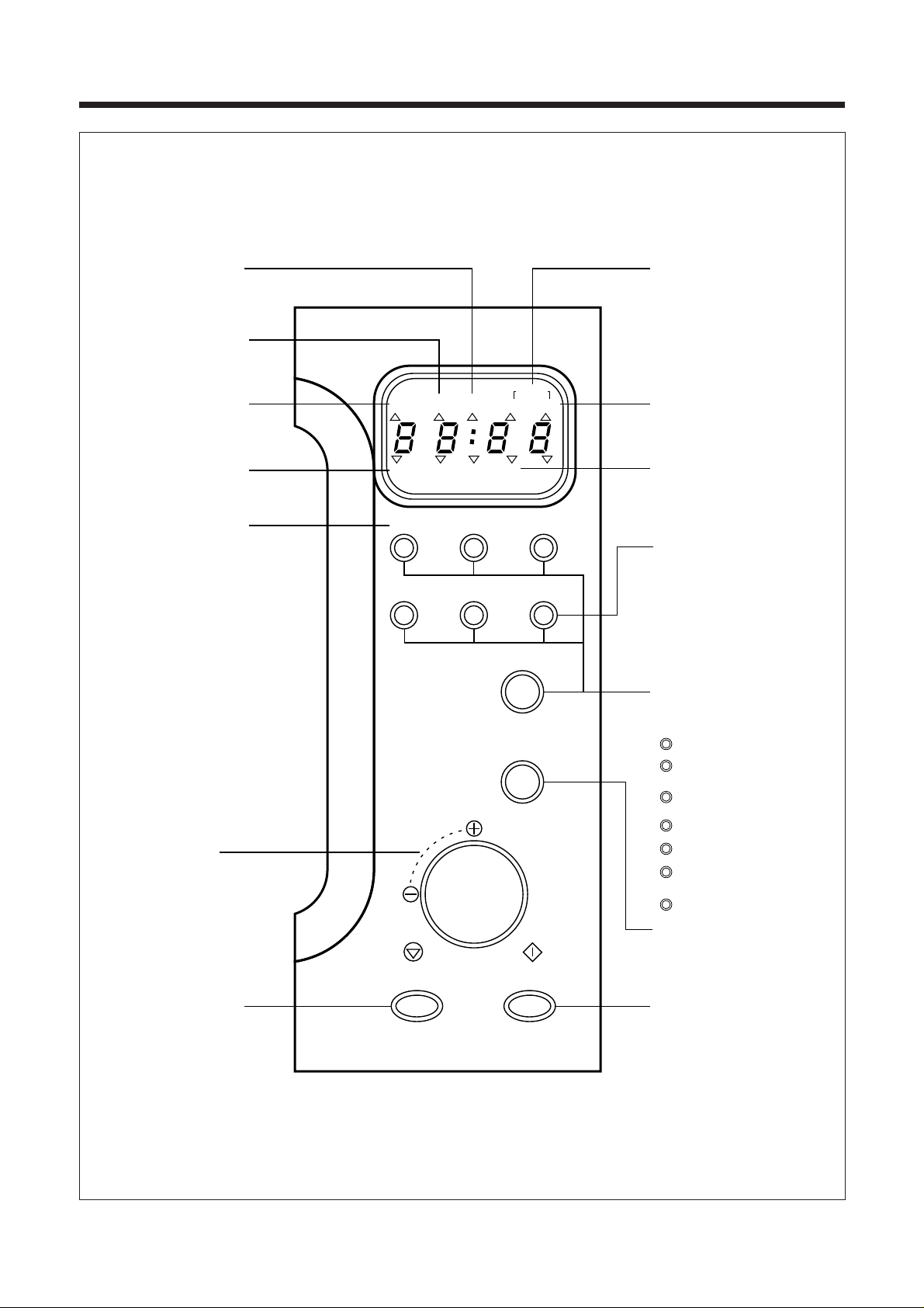
CONTROL PANEL
GRILL COMBI TEMP
M/W DEFROST PIE
PROGRAM COOK
1. ROAST BEEF
2. ROAST PORK
3. ROAST CHICKEN
4. FISH FILLETS
5. VEGETABLE
SPEEDY COOK
STOP/CLEAR START
PROGRAM
COOK
KgTEMP
COOK
PIE
M/W GRILL COMBI
WEIGHT
DEFROST
TIME
When blinking, the oven is
operating in COMBI cooking.
When blinking, the oven is
operating in WEIGHT
DEFROST.
When blinking, the oven is
operating in GRILL
When blinking, the oven is
operating in MIROWAVE
COOK
When blinking, the oven is
operating in PROGRAM.
Microwave Power Level-
Used to select the variable
microwave power level. If this
button is pressed for more
tan 1.3 seconds, number is
scrolled up automatically.
DIAL KNOB -Used to
enter the cooking time and
weight input.
Stop/Clear Button -Used
to pause or clear all
information manually put into
the oven.
When blinking, the oven is
operating in TIME DEFROST.
When blinking, the oven is
operating in weight input
mode.
Temperature Button Used to set desired
temperature. If this
button pressed for more
than 1.3 seconds, number
is scrolled up automatically.
Function Button - Used to
select desired oven operation.
MICROWAVE
GRILL
WEIGHT DEFROST
TIME DEFROST
CONVECTION
(TEMP COOK)
COMBINATION
PIE
PROGRAM COOK
Start Button - Used to
start the selected cycle.
Speedy Cook Button - Used
to quickly program cooking
time in 30 seconds
increments.
M/W
GRILL
DEFROST
COMBI
+1MIN
+10SEC
PROGRAM
COOK
6
OPERATION
TO STOP THE OVEN WHILE THE OVEN IS OPERATING
1. Press (STOP / CLEAR) button.
- The (STOP) indicator starts blinking.
- You can restart the oven by touching (START) button.
- Touch once more to erase all instruction except clock.
2. Open the door
- You can restart the oven by closing the door and touching button.
ERASING INSTRUCTIONS
• Touch (STOP/CLEAR) button to erase all instructions you set previously.
• Opening the oven door during cooking dose not erase cooking instruction.
• If you touch button during operation, the cooking instructions is all erased.
NOTE : Oven stops operating when door open.
7
The door lock mechanism is a device which has been specially designed to completely eliminate microwave radiation when
the door is opened during operation, and thus to perfectly prevent the danger resulting from the leakage of microwave.
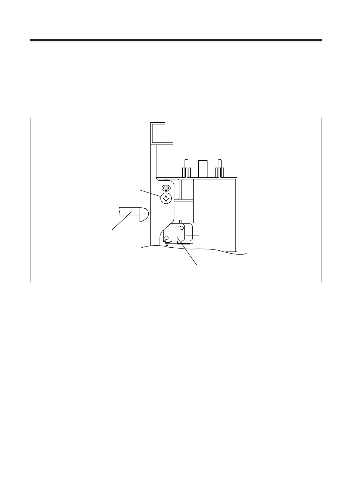
(1) Primary interlock switch
When the door is closed, the hook locks the oven door.
If the door is not closed properly, the oven will not operate.
When the door is closed, the hook pushes the primary interlock switch.
The hook press the button of the primary interlock switch to bring it under ‘ON’ condition.
INTERLOCK MECHANISM FUNCTIONS AND ADJUSTMENTS
Mounting
screw
Hook
Primary
interlock
switch
8
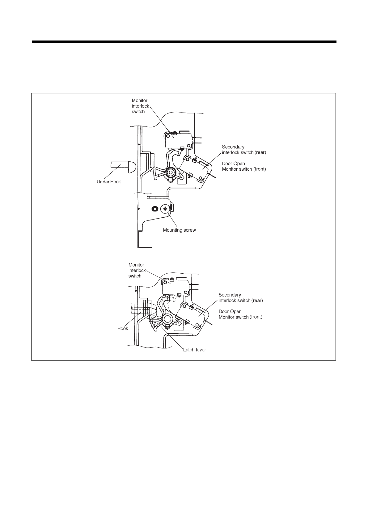
(2) Monitor interlock switch
When the door is closed, the hook pushes the lever forward, and pushes the Latch Lever downward the lever press the
button of the interlock monitor switch to bring it under ‘OFF’ condition. The latch Lever press the button on the secondary
interlock switch to bring it under ‘ON’ condition.
- Adjustment
Interlock monitor switch
When the door is closed, the monitor switch should be opened before other switches close.
When the door is opened, the monitor switch should be closed after other switches open.
Adjustment steps :
a) Loosen the two mounting screws.
b) Adjust the interlock switch assembly position.
c) Make sure that the latch lever moves smoothly after adjustment is completed.
d) Completely tighten the two mounting screws.
9
PRECA UTIONS FOR DISASSEMBLY AND REPAIR
-
Cautions to be observed when trouble shooting.
Unlike many other appliances, the microwave oven is high-voltage, high-current equipment. It is completely safe during
normal operation. However, carelessness in servicing the oven can result in an electric shock or possible danger from a
short circuit.
You are asked to observe the following precautions carefully.
(1)Always remove the power plug from the outlet before servicing.
(2)Use an insulated screwdriver and war rubber gloves when servicing the high voltage side.
(3)Warning about the electric charge in the high voltage capacitor. When inspecting and repairing the high voltage side,
always short the capacitor terminals and make sure of discharge.
1. Check the earthing.
Do not operate on a 2-wire extension cord.
The microwave oven is designed to be used when earthed.
It is imperative, therefore, to makes sure it is earthed
properly before beginning repair work.
2. Warning about the electric charge
in the high voltage capacitor.
For about 30 seconds after the operation stops, electric charge
remains in the high voltage capacitor. When replacing or
checking parts, short between oven chassis and the negative
high terminal of the high voltage capacitor, by using a properly
insulated screw driver to discharge.
(4)When the 15 Amp fuse (normal blow type) is blown out due to the operation of the monitor switch; replace primary,
secondary interlock switch and monitor switch. Refer to 17 page for the necessary adjustment.
(5)After repair or replacement of parts, make sure that the screws are properly tightened and all electrical connections are
tightened.
(6)Do not operate without cabinet.
CAUTION : Service personnel should remove their watches whenever working close to or repairing the magnetron.
WARNING : When servicing the appliance, need a care of touching or replacing high potential parts because of
electrical shock or exposing microwave. These parts are as follows - H.V. Transformer, magnetron,
H.V. Diode, H.V. Capacitor.
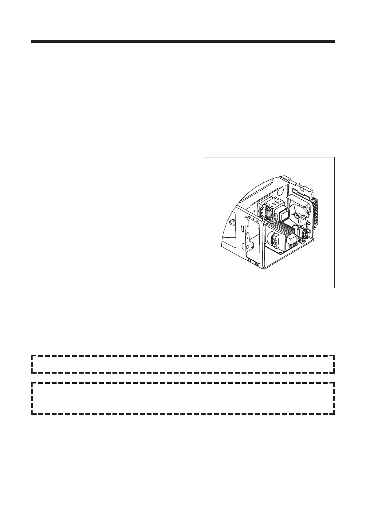
10
1. T o remo ve cabinet. (Refer to Fig. 1)
1) Remove four screws on cabinet back.
2) Push the cabinet backward.
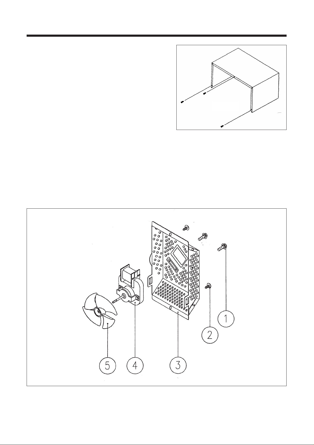
2. T o remo ve guide wind assembl y. (Refer to Fig. 2)
1) Release two screws ¤Ł.
2) Remove back-cover ¤Ø.
3) Pull the fan
¤ºto the motor shaft.
4) Release two screws
¤ which secure the motor shaded pole ¤Œ.
5) Reverse the above steps for reassembly.
DISASSEMBLY AND ASSEMBLY
Fig. 1
Fig. 2
11
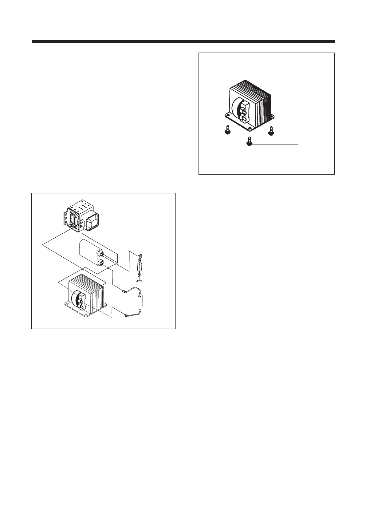
3. To remove H.V. transformer . (Refer to Fig. 3)
1) Remove four screws ¤ which secure the
H.V. Transformer bracket to the base plate.
2) Remove the H.V. Transformer
¤Ł.
High voltage circuit wiring
Fig. 3
H.V. Trans
H.V. Copacitor
Mognetron
H.V.Diode
H.V.Fuse
2
1
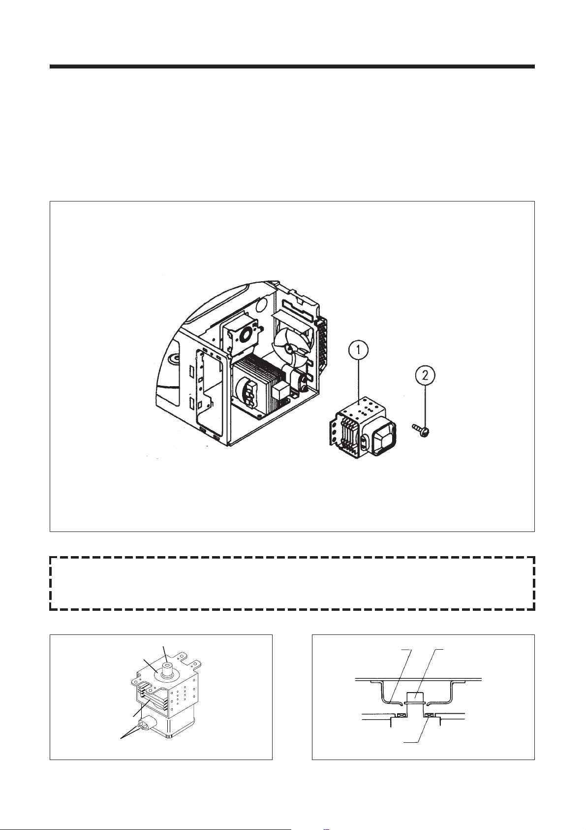
4. T o remo ve magnetr on. (Ref er to Fig. 4)
1) Remove three screws ¤Łwhich secure the magnetron ¤ .
2) Remove the magnetron.
3) Reverse the above steps for reassembly.
12
Fig. 4
CAUTION : Never install the magnetron without the metallic gasket plate which is packed with each magnetron to
prevent microwave leakage. Whenever repair work is carried out on magnetron, check the microwave
leakage. It shall not exceed 4mW/cm
2
for a fully assembled oven with door normally closed.
Magnetron antenna
Wave guide
Magnetron antenna
Metallic gasket plate
Metallic
gasket
plate
Cooling fin
<Magnetron>
Filament terminal
13
Fig. 5
Fig. 6
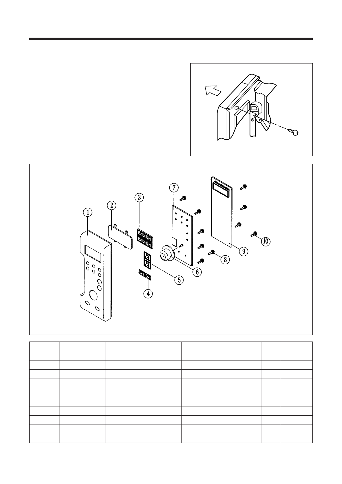
5. To remove control panel assembl y. (Refer to Fig. 5, 6)
(1) Remove a screw holding control panel assembly to the oven
front plate.
At the same time, draw forward the control panel assembly
from oven front plate.
(2) Remove ten screws
¤ , ¤ which secure the main and sub
PCB assembly
¤ , ¤ to control panel ¤ .
(3) Remove buttons
¤Ø, ¤Œ, ¤º.
(4) Remove the Window display ¤Ł.
REF NO. PART CODE PART NAME DESCRIPTION Q’TY REMARK
1 3516716320 CONTROL PANEL ABS 1
2 3515501210 WINDOW DISPLAY PMMA 1 SMOG
3 3516905100 BUTTON FUNCTION ABS 1
4 3516906300 BUTTON FUNCTION ABS 2
5 3516906200 BUTTON FUNCTION ABS 1
6 3613404600 KNOB VOLUME ABS 1
7 3516314800 PCB SUB AS KOC-872T 1
8 7121030811 SCREW TAPPING T2S PAN 3X8 MFZN 6
9 3514314720 PCB MAIN AS KOC-872T 1
10 7121030811 SCREW TAPPING T2S PAN 3X8 MFZN 4
14
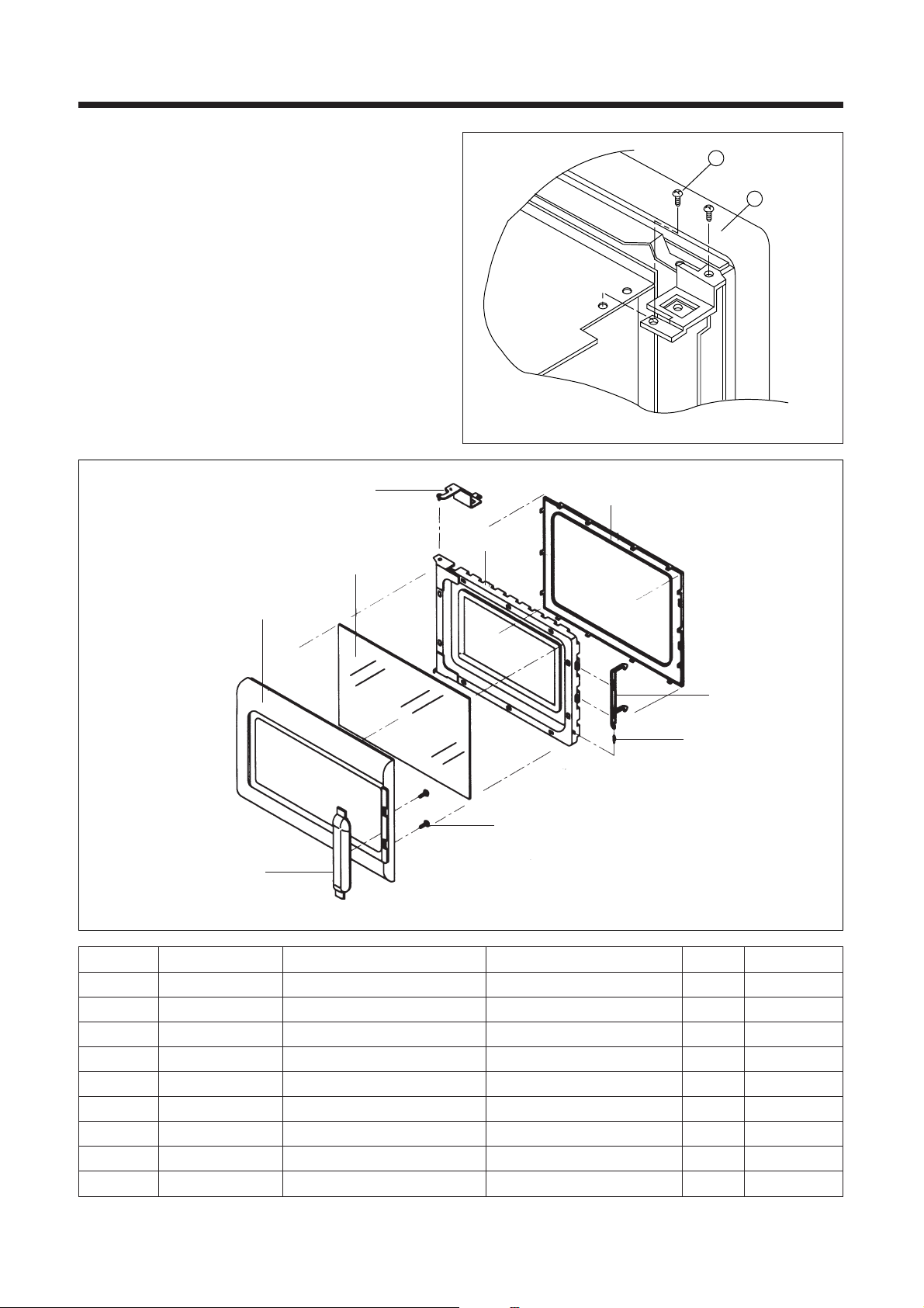
6. To remove door assembly. (Refer to Fig. 7)
1) Remove two screws 1 which secure to hinge.
2) Remove door assembly
2.
3) Remove door above for reassembly taking case to
replace fixing glue.
7. To remove door part. (Refer to Fig. 8)
(1) Remove the Gasket door 8.
(2) Remove the Door seal Ass’y 1.
(3) Remove the Hook
2 and Spring 3.
(4) Remove the Barrier Screen
4.
(5) Remove the Handle
6 form the Frame door 5.
2
1
REF NO. PART CODE PART NAME DESCRIPTION Q’TY REMARK
1 3511709000 DOOR SEAL AS KOC-871C0S 1
2 3513101300 HOOK POM 1
3 3515101300 SPRING HOOK PW1 1
4 3517004500 BARRIER-SCREEN *0 TEMPERED GLASS 3.2T 1
5 3512203530 FRAME DOOR ABS XR-401 1
6 3512601510 HANDLE DOOR ABS SG-175 1
7 3515203600 STOPPER HINGE *T AS KOC-970T1S 1
8 3512301300 GASKET DOOR PBT 1
9 7S341W40B1 SCREW TAPPING T2S PAN 4X12 PW SE 2
Fig. 7
Fig. 8
7
6
9
3
2
5
4
1
8
 Loading...