


Daewoo DTD-20D3, DTD-14D7, DTD-20D4, DTD-21D6, DTD-21D3 Service Manual
...
Service Manual
Items Model DTD-14D3/20D3/21D3 ME/MT/MP/MZ
14D4/20D4/21D4 ME/MT/MP/MZ
14D6/21D6 ME/MT/MP/MZ
14D7/20D7/21D7 ME/MT/MP/MZ
21U6/21U8 ME/MT/MP/MZ
TV Standards PAL-SECAM-B/G,D/K,I,NTSC-M,NTSC-4.43(AV)
Mains V oltage AC 100~250V , 50/60Hz
Power Consumption Stand-by mode : 5W
Normal Operating Mode : 14”=85W, 20”=95W, 21”=105W, 21”(flat)=115W
Sound Ouput1 14/20”=5W+5W Over(80% MOD.at 1KHz THD.10%)
21U6=5W+5W Over(80% MOD.at 1KHz THD.10%)
21”,21U8=7W+7W Over(80% MOD.at 1KHz THD.10%)
Speaker 14/20”=7.5W 8 Ohm (2pcs)
21U6=5W 8 Ohm (2pcs) , 21”,21U8=12W 8 Ohm (2pcs)
Antenna 75 Ohm Unbalanced. (DIN Standard)
Tuning System FS Tuning System
Memory Channel 100 Channels
Remocon Control R-44C07
Reception Channel VHF - BAND1 : CH2-CH4
BAND2 : CH5-CH12
CABLE BAND : S1’-S3, S1-S20
HYPER BAND : S21-S41
UHF-BAND : CH21-CH69
Remark OSD
TELETEXT (Top & Flop Teletext)
PIP(AV PIP, Swap, Size, Position)
Digital Eye
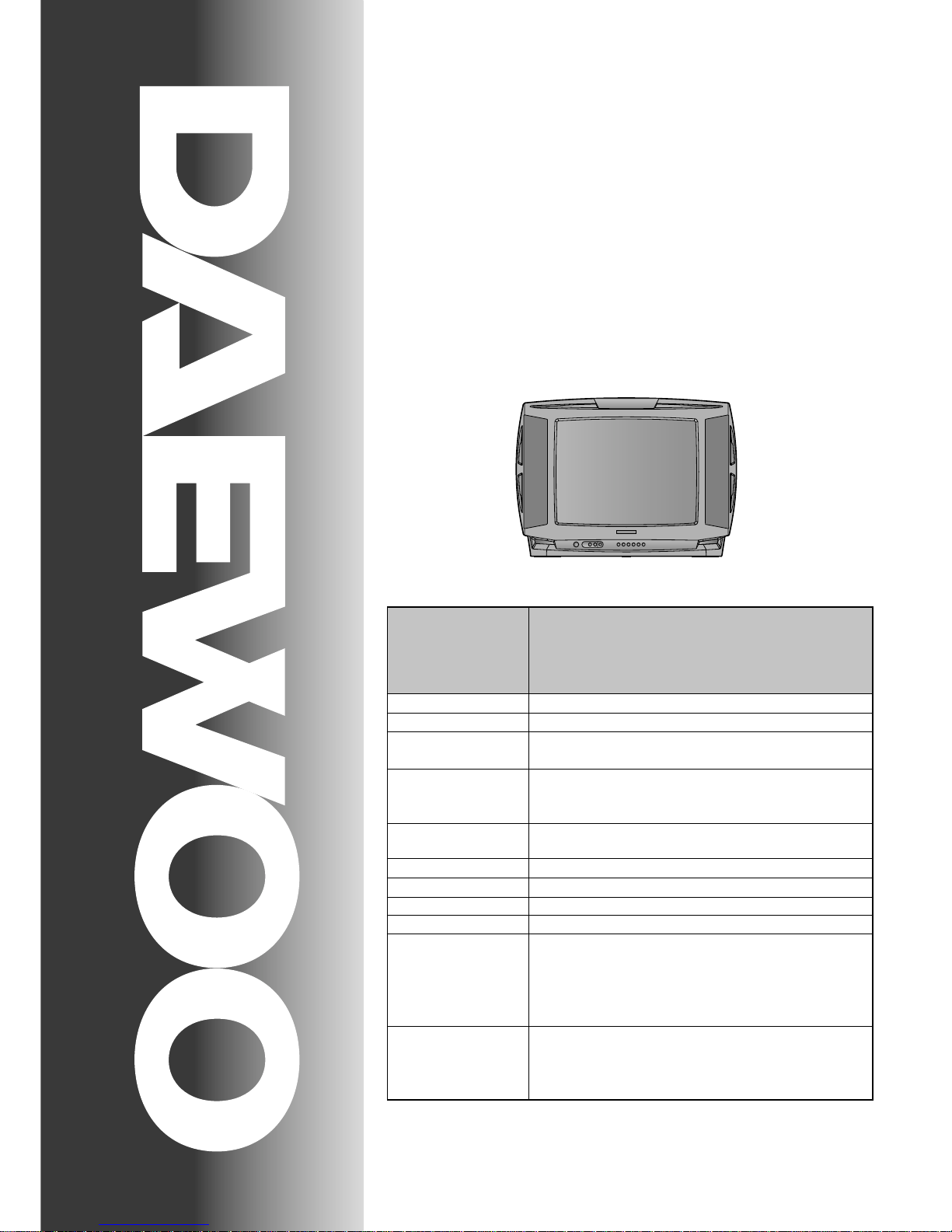
Colour Television
CHASSIS : CM-905S/SF
Model :
DTD-
14D3/20D3/21D3 ME/MT/MP/MZ
14D4/20D4/21D4 ME/MT/MP/MZ
14D6/21D6 ME/MT/MP/MZ
14D7/20D7/21D7 ME/MT/MP/MZ
21U6/21U8 ME/MT/MP/MZ
S/M No. : TCM905SEF0
DAEWOO ELECTRONICS CO., LTD
http : //svc.dwe.co.kr June.2001
Specification

- 1 -
TABLE OF CONTENTS
SPECIFICATIONS .............................................................................................................. 2
SAFETY INSTRUCTION .................................................................................................... 3
CIRCUIT BLOCK DIAGRAM ............................................................................................. 4
ALIGNMENT INSTRUCTIONS .......................................................................................... 5
CM-905S/SF TYPICAL SERVICE DATA ............................................................................ 8
SCHEMATIC DIAGRAM ..................................................................................................... 11
PRINTED CIRCUIT BOARD .............................................................................................. 12
MECHANICAL EXPLODED VIEW AND PARTS LIST ...................................................... 13
ELECTRICAL PARTS LIST ............................................................................................... 19
CM-905S/SF EACH MODEL PARTS LIST ........................................................................ 29
APPENDIX (“Appendix is provided only by internet [http://svc.dwe.co.kr]”)
IC DESCRIPTION .............................................................................................................. 1
TROUBLE SHOOTING CHARTS ...................................................................................... 19
- 2 -
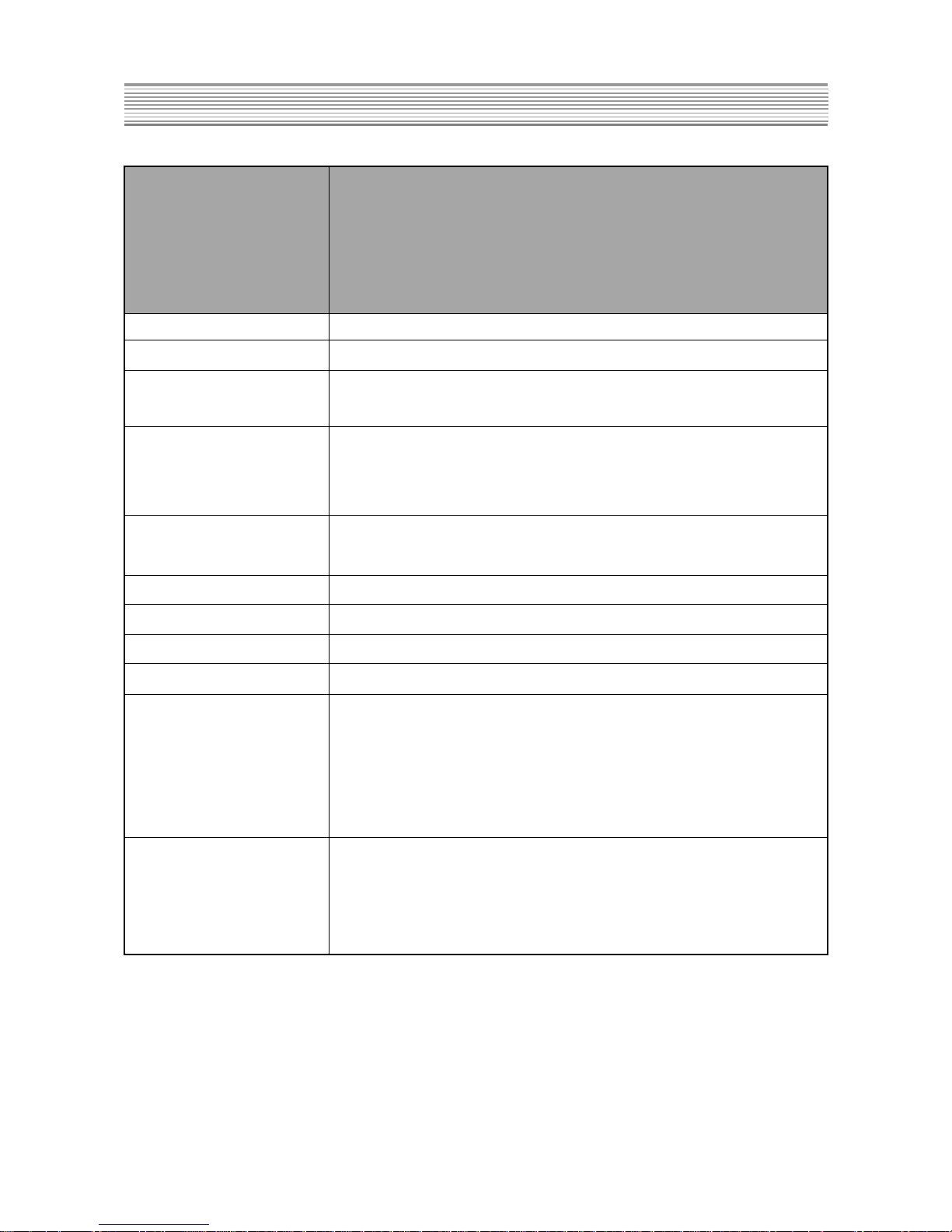
Items Model DTD-14D3/20D3/21D3 ME/MT/MP/MZ
14D4/20D4/21D4 ME/MT/MP/MZ
14D6/21D6 ME/MT/MP/MZ
14D7/20D7/21D7 ME/MT/MP/MZ
21U6/21U8 ME/MT/MP/MZ
TV Standards PAL-SECAM-B/G,D/K,I,NTSC-M,NTSC-4.43(AV)
Mains Voltage AC 100~250V , 50/60Hz
Power Consumption Stand-by mode : 5W
Normal Operating Mode :
14”=85W, 20”=95W, 21”=105W, 21”(flat)=115W
Sound Ouput1 14/20”=5W+5W Over(80% MOD.at 1KHz THD.10%)
21U6=5W+5W Over(80% MOD.at 1KHz THD.10%)
21”,21U8=7W+7W Over(80% MOD.at 1KHz THD.10%)
Speaker 14/20”=7.5W 8 Ohm (2pcs)
21U6=5W 8 Ohm(2pcs) , 21”,21U8=12W 8 Ohm (2pcs)
Antenna 75 Ohm Unbalanced. (DIN Standard)
Tuning System FS Tuning System
Memory Channel 100 Channels
Remocon Control R-44C07
Reception Channel VHF - BAND1 : CH2-CH4
BAND2 : CH5-CH12
CABLE BAND : S1’-S3, S1-S20
HYPER BAND : S21-S41
UHF-BAND : CH21-CH69
Remark OSD
TELETEXT (Top & Flop Teletext)
PIP(AV PIP, Swap, Size, Position)
Digital Eye
SPECIFICATIONS
CAUTION
- 3 -
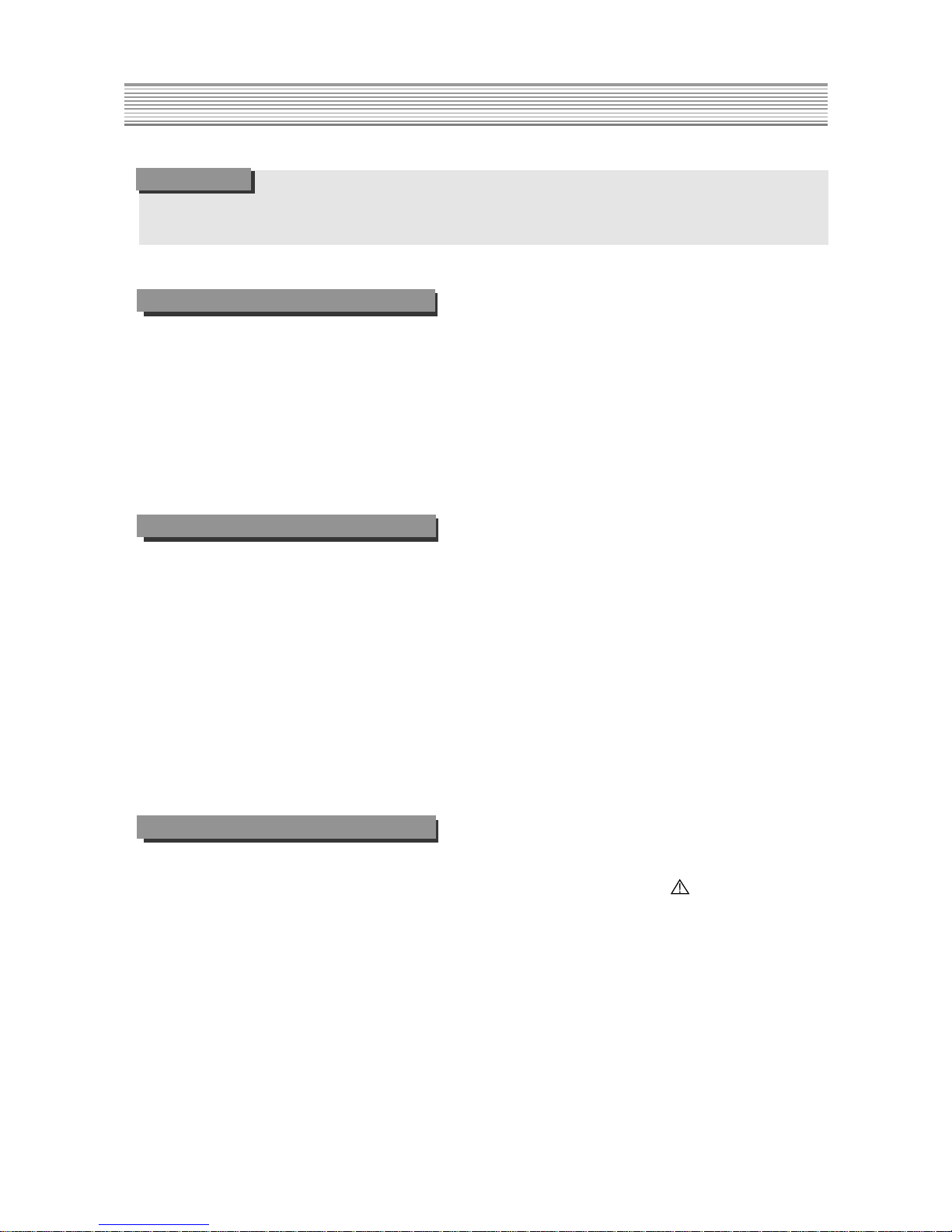
SAFETY INSTRUCTION
CAUTION
NOTE
BEFORE SERVICING THIS CHASSIS READ THE “X-RAY RADIATION PRECAUTIONS”,
“SAFETY PRECAUTIONS” AND “PRODUCT SAFETY NOTICE” BELOW.
X-RA Y RADIATION PRECAUTIONS
1. Excessive high voltage can produce potentially hazardous X-RAY RADIA TION. To avoid such hazards, the
high voltage must not exceed the specified limit. The
nominal value of the high voltage of this receiver is
25kV(21”) at max beam current. The high voltage must
not, under any circumstances, exceed 27kV(21”).
Each time a receiver requires servicing, the high voltage should be checked. It is recommended the reading
SAFETY PRECAUTIONS
1. Potentials of high voltage are present when this
receiver is operating. Operation of the receiver outside
the cabinet or with the back cover removed involves a
shock hazard from the receiver.
1) Servicing should not be attempted by anyone who is
not thoroughly familiar with the precautions necessary
when working on high voltage equipment.
2) Always discharge the picture tube to avoid the shock
harzard before removing the anode cap.
3) Discharge the high potential of the picture tube before
handling the tube. The picture tube is highly evacuated
and if broken, glass fragments will be violently expelled.
PRODUCT SAFETY
Many electrical and mechanical parts in this chassis have
special safety-related characteristics.
These characteristics are often passed unnoticed by a
visual inspection and the X-RA Y RADIA TION protection
afforded by them cannot necessarily be obtained by using
replacement components rated for higher voltage, wattage,
etc.
Replacement parts which have these special safety characteristics are identified in this manual and its supple-
ments, electrical components having such features are
identified by designated symbol on the “P ART LIST”.
Before replacing any of these components, read the “PA RT
LIST” in this manual carefully .
The use of substitute replacement part which do not have
the same safety characteristics as specified in the “P ART
LIST” may created X-RA Y RADIATION.
of the high voltage recorded as a part of the service
recorded as a part of the service records. It is important
to use an accurate and reliable high voltage meter.
2. The only source of X-RAY RADIA TION in this TV
receiver is the picture tube. For continuous RADIATION
protection, the replacement tube must be exactly the
same type tube as specified in the “PA RT LIST”.
2. If any FUSE in this TV receiver is blown, replace it will
the FUSE specified in the “P ART LIST”.
3. When replacing a high wattage resistor (oxide metal
film resistor) in circuit board, keep the resistor 10mm
away from circuit board.
4. Keep wires away from high voltage or high temperature
components.
5. This receiver must operate between AC 100~240 volts,
50/60Hz. NEVER connect to DC supply or any other
power or frequency.
- 4 -
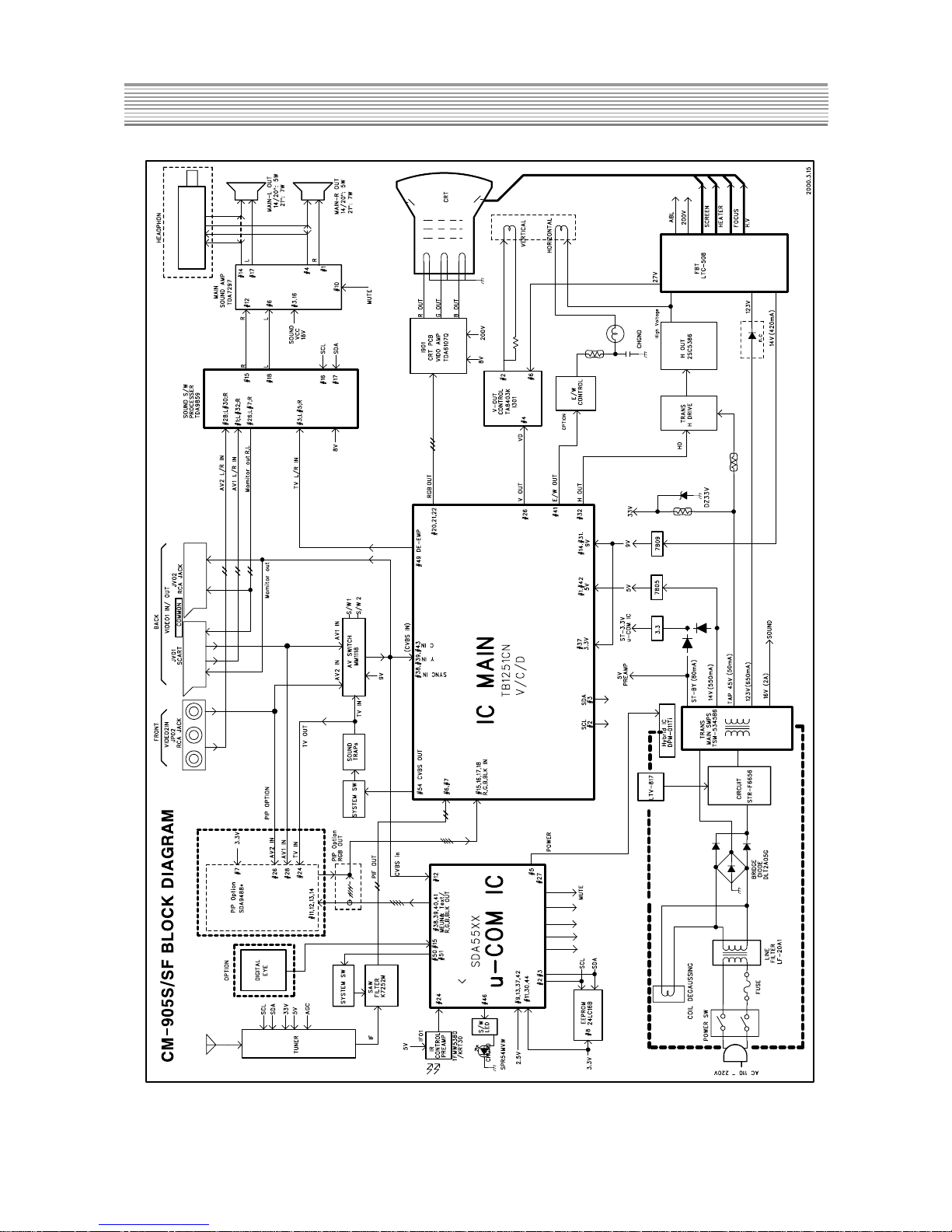
CIRCUIT BLOCK DIAGRAM
CAUTION

- 5 -
ALIGNMENT INSTRUCTIONS
CAUTION
1. AGC ADJUSTMENT
1) Pattern : P AL B/G 10CH Color BAR (RF Level = 60 dB)
2) Connect the Pattern Generator RF Output to Tuner RF Input.
3) Press the S10 Key of Service Remocon to enter the “AGC MODE”.
4) Execute the “AUTO AGC” using the V ol-Up Key.
2. SCREEN ADJUSTMENT
1) Pattern : PAL B/G Retma
2) Press the NORMAL Key to set the “NORMAL 1” mode.
3) Press the S2 Key of Service Remocon.
4) Adjust the SCREEN VOLUME on FBT so that the horizontal line reach the cut-off point.
3. FOCUS ADJUSTMENT
1) Pattern : PAL B/G Retma
2) Adjust the FOCUS VOLUME on FBT to obtain clear resolution.
4. WHITE BALANCE ADJUSTMENT
1) Press the NORMAL Key to set the “NORMAL 1” mode.
2) Press the S8 Key of Service Remocon to enter the “WHITE BALANCE” mode.
3) Adjust the each color ( R,G,B ) which appears abnormally on the screen.
5. GEOMETRIC ADJUSTMENT
1) Press the NORMAL Key to set the “NORMAL 1” mode.
2) Press the S6 Key of Service Remocon to enter the “GEOMETRIC” mode.
5-1. VERTICAL CENTER ADJUSTMENT
1) Pattern : P AL B/G Retma
2) Choose the “V-CENTER” using the Pr-Up/Down Keys.
3) Adjust the horizontal line of picture to coincide with the mechanical center marks of the CRT using the
Vol-Up/Down Keys.
*
If the pattern is smaller than the screen, adjust the V-size to fit.
5-2. VERTICAL SIZE ADJUSTMENT
1) Pattern : P AL B/G Retma
2) Choose the “V-SIZE” using the Pr-Up/Down Keys.
3) Adjust the vertical size of the picture using the Vol-Up/Down Keys.

- 6 -
5-3. HORIZONT AL CENTER ADJUSTMENT
1) Pattern : PAL B/G Retma
2) Choose the “H-CENTER” using the Pr-Up/Down Keys.
3) Adjust the vertical line of picture to coincide with the mechanical center marks of the CRT using the
Vol-Up/Down Keys.
5-4. HORIZONTAL SIZE ADJUSTMENT
1) Pattern : P AL B/G Retma
2) Choose the “H-SIZE” using the Pr-Up/Down Keys.
3) Set each side over scan to be 10% using the Vol-up/Down Keys.
5-5. PINCUSHION ADJUSTMENT
1) Pattern : P AL B/G Crosshatch
2) Choose the “PARABOLA” using the Pr-Up/Down Keys.
Adjust parabola width to fit on screen.
3) Choose the “CONER” using the Pr-Up/Down Keys.
Adjust coner parabola to fit on screen.
4) Choose the “TRAPEZIUM” using the Pr-Up/Down Keys,
Adjust trapezium to fit on screen.
5-6. S-CORRECTION ADJUSTMENT
1) Pattern : P AL B/G Crosshatch
2) Choose the “S-CORRECTION” using the Pr-Up/Down Keys.
3) Adjust each distance of horizontal line to be the same using the Vol-Up/Down Keys.
5-7. SUB-BRIGHTNESS ADJUSTMENT
1) Pattern : PAL B/G Retma
2) Press the NORMAL Keys to set the “NORMAL 1” mode.
ALIGNMENT INSTRUCTIONS
- 7 -
ALIGNMENT INSTRUCTIONS
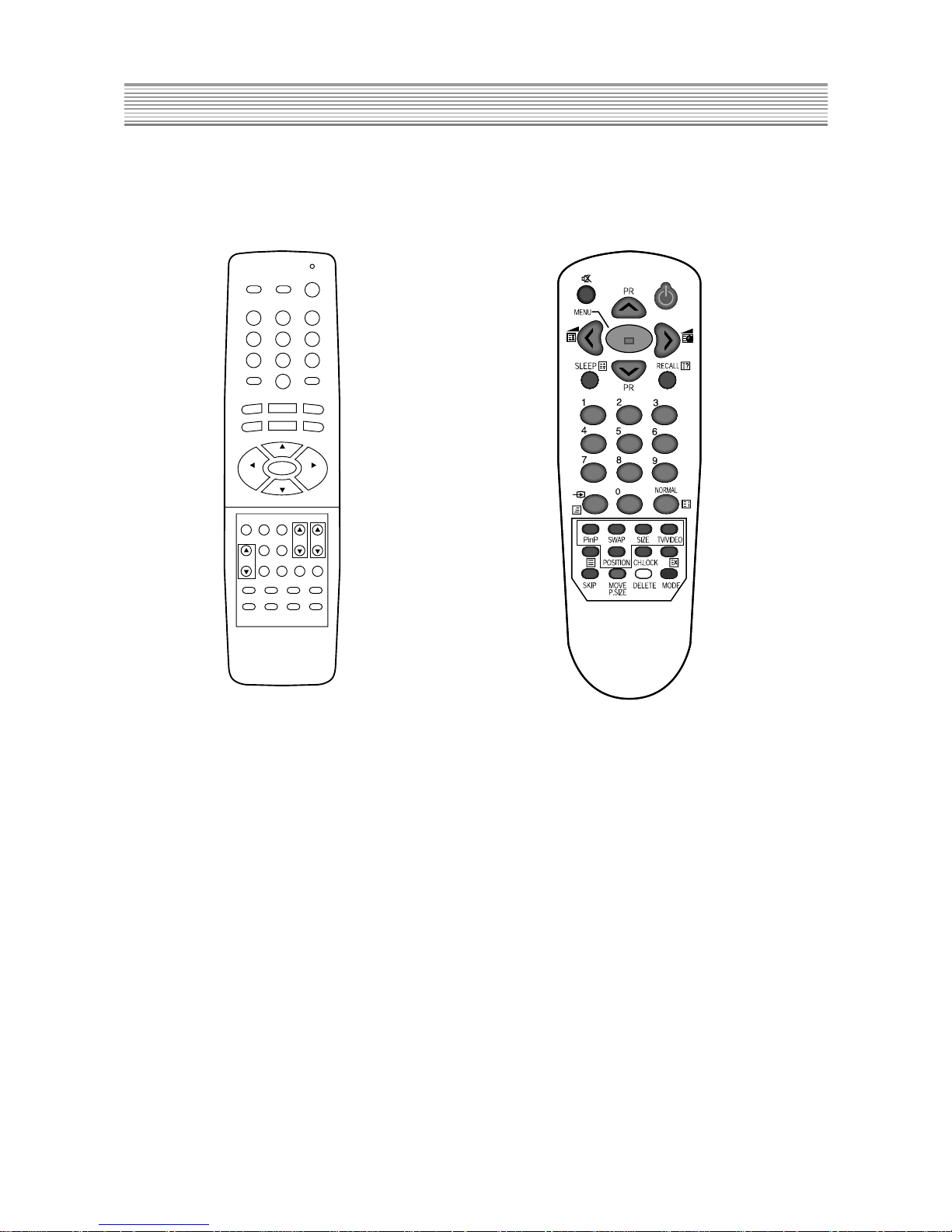
6. REMOCON
6-1. SERVICE REMOCON 6-2. USER REMOCON
6-3. SERVICE REMOCON
1) Enter SERVICE MODE : Press keys of User Remocon, as follows.
Ch91, Sharpness 0, Skip(red), Move(green), Menu.
2) Choice SERVICE MENU : Pr-Up/Down
3) Enter SERVICE SUB MENU : Vol-Up/Down
4) Adjust SERVICE MENU : Vol-Up/Down
S1 S2 S3
S4 S5 S6
S7 S8 S9
S11
RECALL
S10 S12
MUTE
POWER
TV/CATV
ADD/ERASE
TV/VIDEO
SOUND MODE
SURROUND
NOISE CLEAR
CH
VOLVOL
CH
MENU
PIP M/S
CH VOL
VPOSITION
POSITION
TV/VIDEO
PAUSE/
STILL
SIZE SLEEP
1
3456
7
R-34SVC
890
2
- 8 -
CM-905S/SF TYPICAL SERVICE DAT A
CAUTION
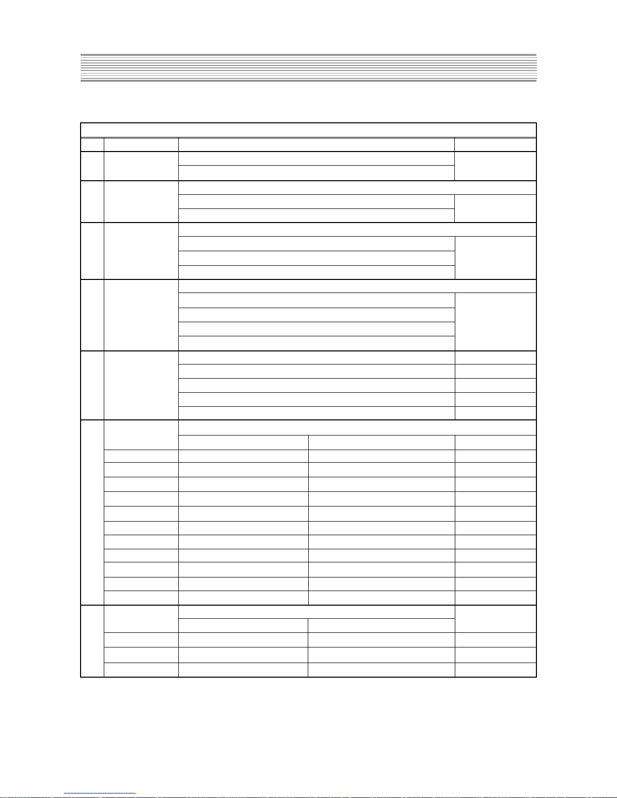
CM-905S/SF SVC KEY & FUNCTION DESCRIPTION
EY N NAME RFUNCTION
PRESS THE S1 ONE TINE ----> PRESS THE S1 ANOTHER TIME
(HEATRUN MODE) (NORMAL OPRATION)
*
FBT SCREEN ADJUSTMENT
PRESS THE S2 ON TIME ----> PRESS THE S2 ANOTHER TIME
(HORIZONTAL KINE) (NORMAL OPRATION)
*
SOUND TEST
PRESS THE S3 KEY IS TOGGLE
VOLUME 00 ----> VOLUME 32 ----> VOLUME 63--->
BALANS LEFT ----> BALANS RIGHT ----> BALANS 00 ----> RELEAS
*
PICTURE TEST
PRESS THE S4 KEY IS TOGGLE
CONTRAST 00 ----> CONTRASR 32 ----> CONTRAST 63 ---->
RRIGHT 00 ----> BRIGHT 32 ----> BRIGHT 63 ---->
COLOR 00 ----> COLOR 32 ----> COLOR 63 ----> RELEASE
*
ADJUST NORMAL1 DAT A INITIAL DAT A
CONTRAST 48 63
RRIGHT 38 23
COLOR 38 32
SHARPNESS 28 32
*
ADJUST GEOMETRY DA T A
21 inch Normal 21 inch Flat Normal INITIAL DAT A(50Hz)
V-CENTER 04 04 04
V-SIZE 54 58 27
H-CENTER 11 12 14
H-SIZE 53 52 58
S6 PARABORA 27 48 27
TRAPEZIUM 15 17 15
CORNER 05 05 05
H-EHT 03 03 03
S-CORRECTION 08 08 07
V-LINEARITY 08 07 09
V-EHT 03 03 03
*
ADJUST PIP DAT A
21 inch Normal 21 inch Flat Normal
R 220 220 128
G 220 220 128
B 220 220 128
S1
HEATRUN MODE
S2
SCREEN
ADJUSTMENT
S3
SOUND TEST
S4
PICTURE TEST
S7
PIP
INITIAL DAT A
Line Production
Line Production
ON/OFF
ON/OFF
NORMAL1
S5
- 9 -
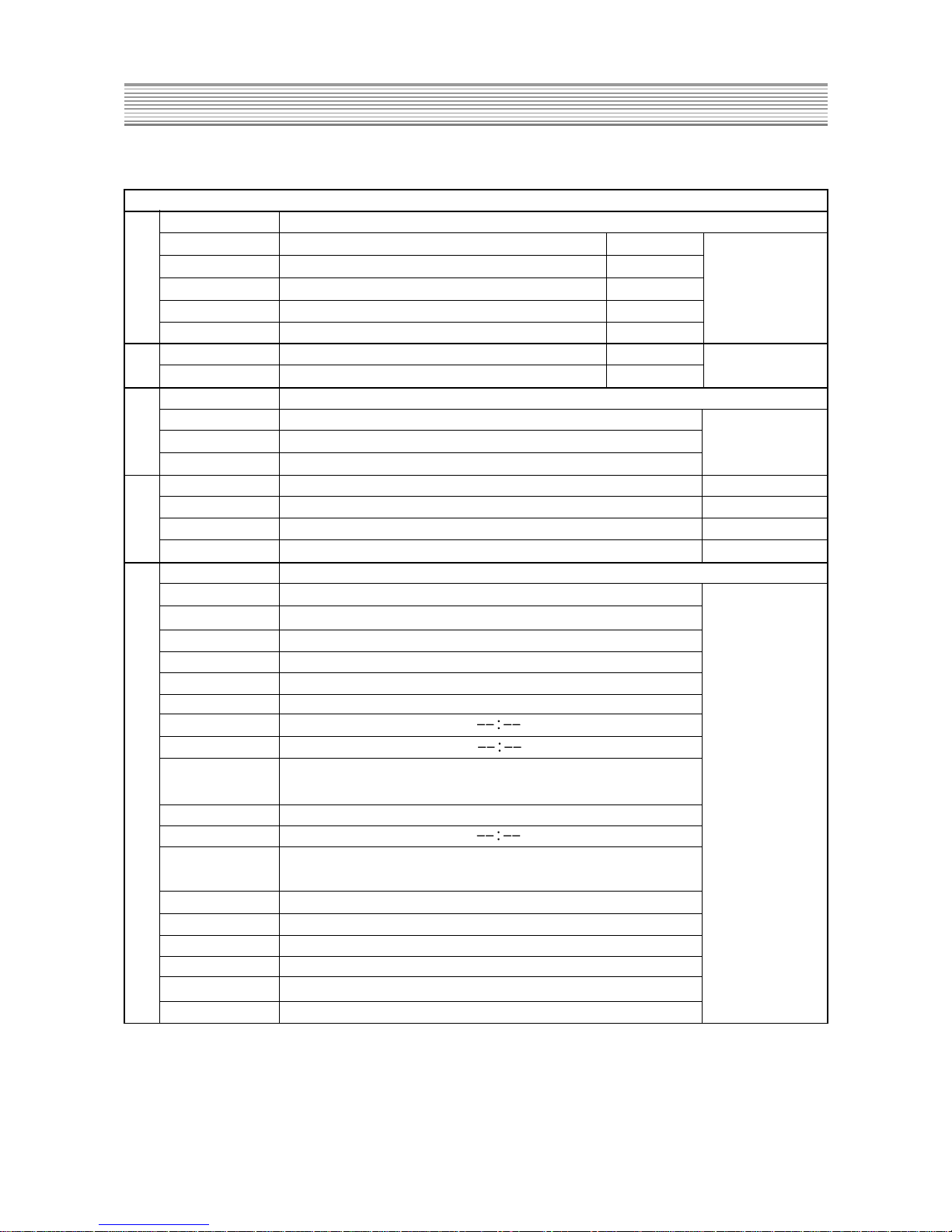
CM-905S/SF SVC KEY & FUNCTION DESCRIPTION
WHITE BALANCE
*
ADJUST WHITE BALANCE DATA
RB R LOW BEAM 127
GB G LOW BEAM 146
BB B LOW BEAM 125
GG G HIGH BEAM 52
BG B HIGH BEAM 52
SUB-BRIGHT ADJUST BRIGHTNESS DA T A 35
SUB-CONTRAST ADJUST SUB CONTRAST DA T A 15
*
MAIN RF AGC ADJUSTMENT KEY
AGC TUNER AGC VOL TAGE 3.5Vdc
AUTO-AGC
DAT A 32
*
OPTION MODE ADJUSTMENT KEY INITIAL DAT A
TEXT ARABIC/CYRILLIC/IRANIAN/EAST-LATIN//WEST-LATIN ARABIC
POWER-ON-STA RT ON/OFF ON
DIGITAL EYE ON/OFF O N
*
OUT DAT A
PICTURE NORMAL 1
BLUE SCREEN ON
BASS CENTER
TREBLE CENTER
BALANCE CENTER
EFFECT OFF
CLOCK
ON TIMER
ON TIMER
ON/OFF
ON PR 1
OFF TIMER
OFF TIMER
ON/OFF
LANGUAGE ENGLISH
COLOR SYSTEM P A L
SOUND SYSTEM BG
SOUND MODE MEMORY
NAME(EACH PR) ----
TV/AV1/AV2 TV
S8
S9
S10
S11
S12
OFF
OFF
CM-905S/SF TYPICAL SERVICE DA TA
- 10 -
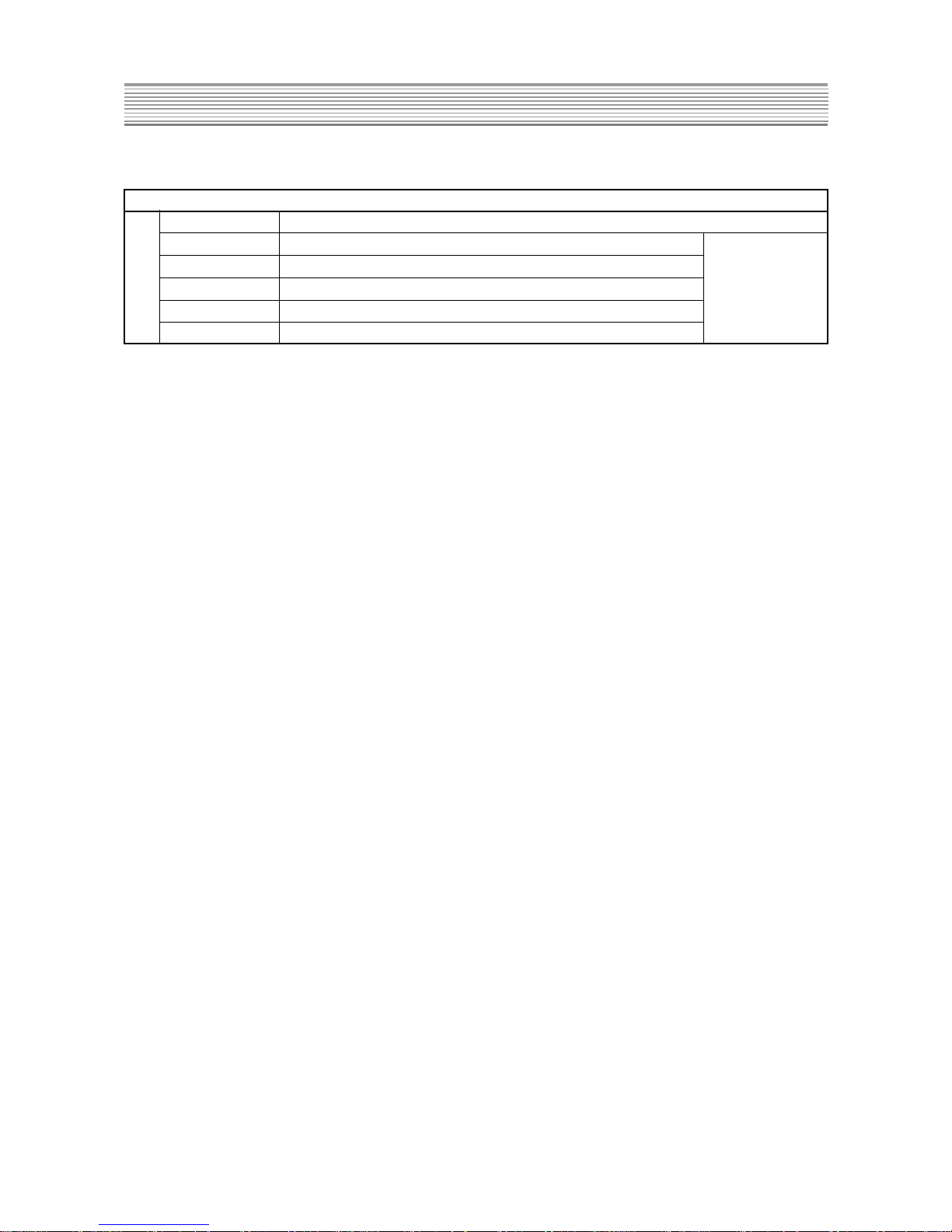
CM-905S/SF SVC KEY & FUNCTION DESCRIPTION
TV/TEXT TV
LAST PR 1
VOLUME
PICTURE SIZE NORMAL ( 4:3 )
CHILD LOCK OFF
CH LOCK OFF
S12
CM-905S/SF TYPICAL SERVICE DA TA
SUB MENU
NO NAME FUNCTION
1 PIP ON / OFF (PIP) ON/OFF display a sub-picture
2 SWAP (PIP) The main picture and sub-picture are swapped
3 SIZE (PIP) The sub-picture will be smaller . To return to be normal size, Press this button again.
4 TV / VIDEO (PIP) To select the input for the sub pictrue
5 POSITION (PIP) The display position of the sub-picture will changed
6 S2 DA TA changed
RB 128
GB 0
SCREEN BB 0
GG 64
BG 64
Brightness 32
7 DIGITAL EYE DIGIT AL DYE funtion ON/OFF
8 ZOOM Picture size changed ( 4:3 -> 16:9 -> ZOOM -> 4:3 ->
...
. )
9 TEXT TEXT funtion ON/OFF
10 CH UP USING the SERVICE MODE to CH UP/DOWN
11 CH DOWN
12 RESISTER
13 RELEASE
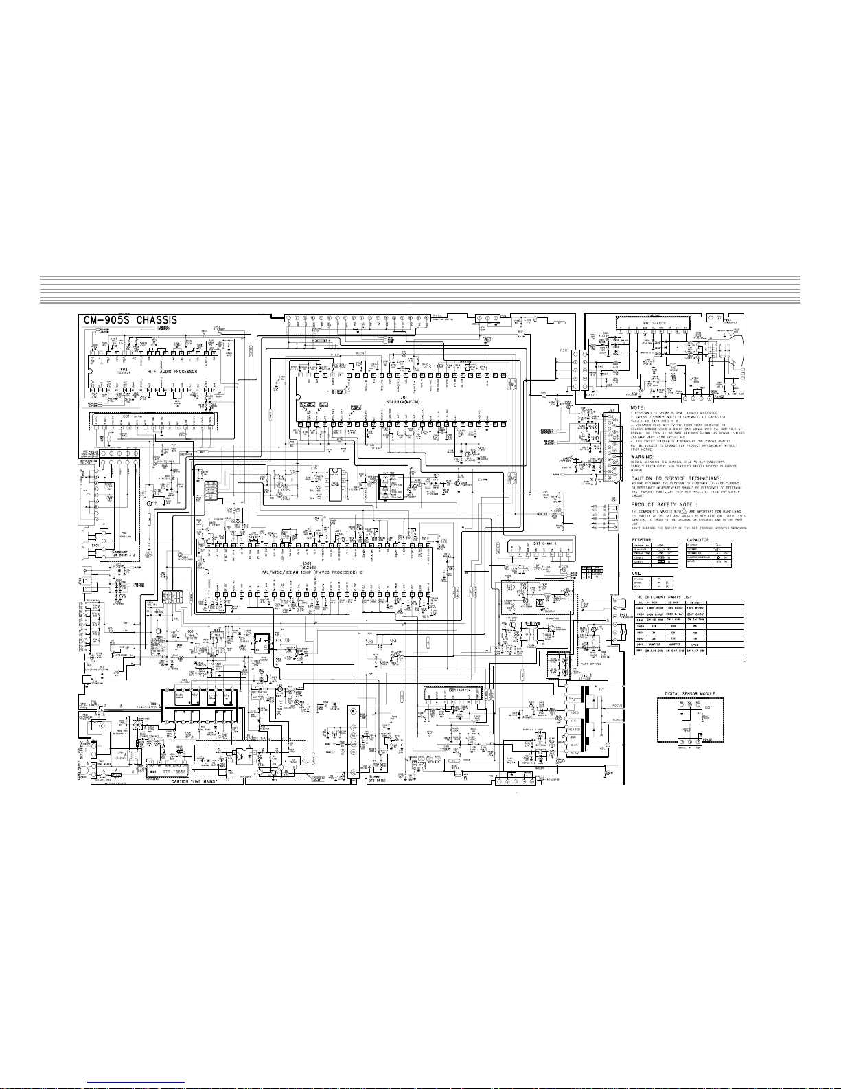
SCHEMATIC DIAGRAM
- 11 -
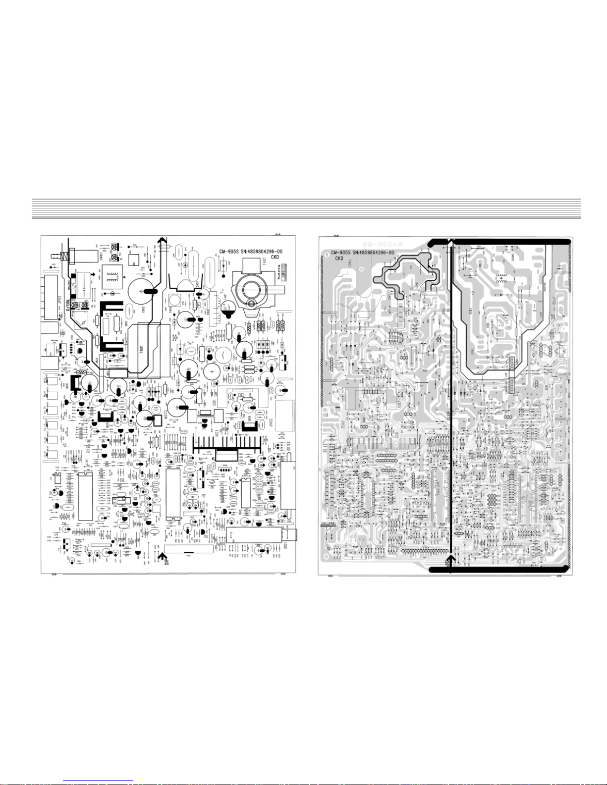
PRINTED CIRCUIT BOARD
PCB MAIN
- 12 -
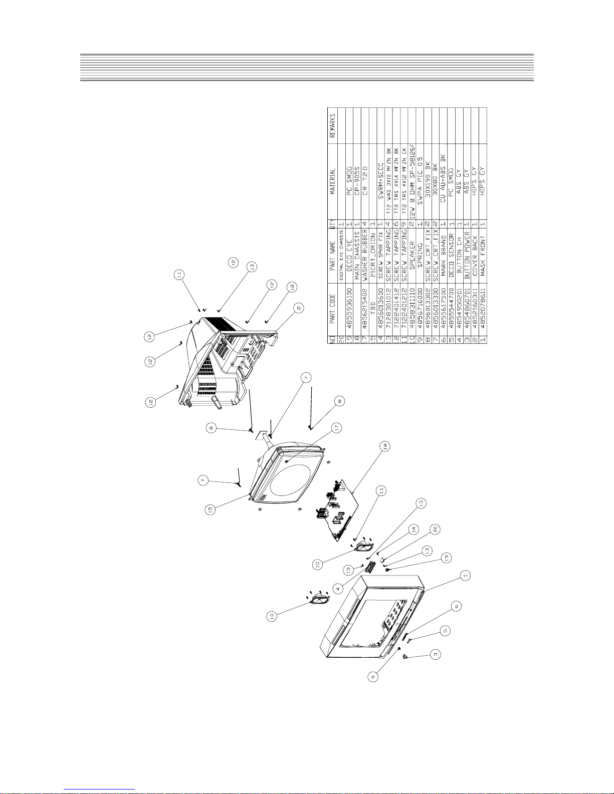
- 13 -
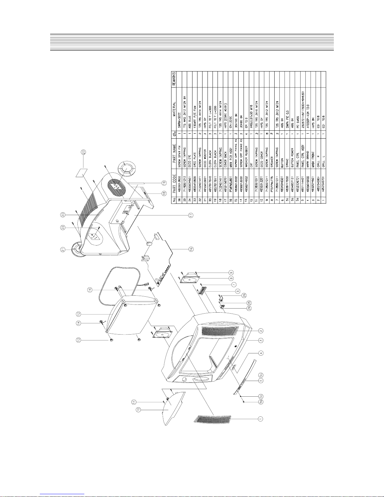
MECHANICAL EXPLODED VIEW AND PARTS LIST
CAUTION
1. DTD-21D7
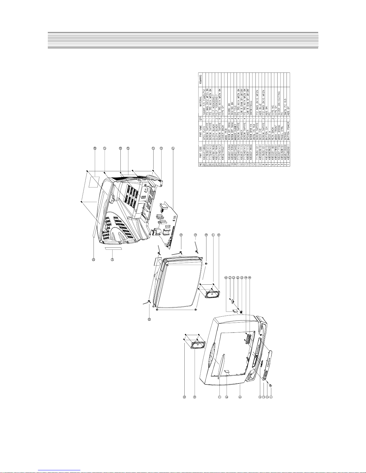
- 14 -
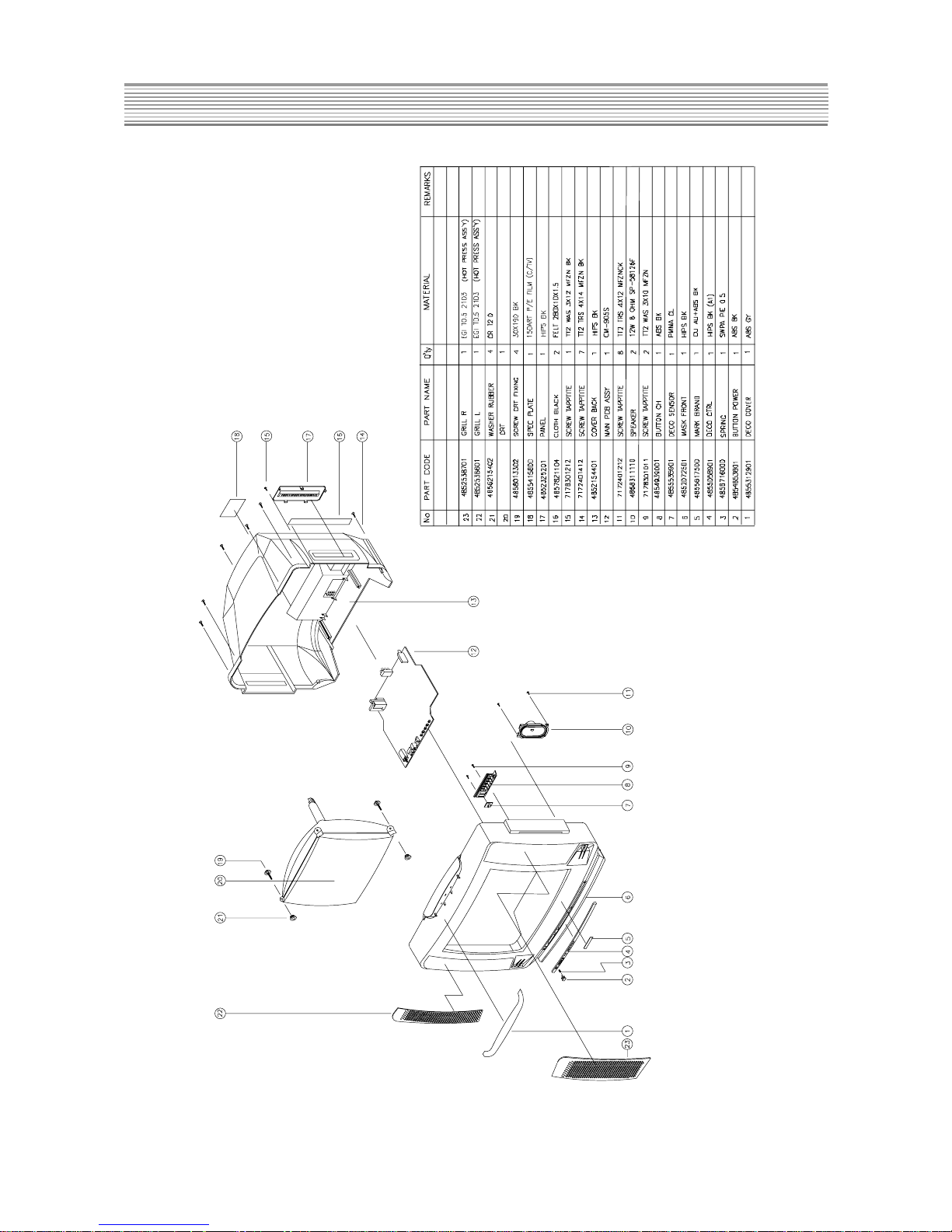
MECHANICAL EXPLODED VIEW AND PARTS LIST
2. DTD-21D6
- 15 -
MECHANICAL EXPLODED VIEW AND PARTS LIST
3. DTD-21D4
- 16 -
MECHANICAL EXPLODED VIEW AND PARTS LIST
4. DTD-21D3
 Loading...