

Page 1
HEAD OFFICE(FACTORY)
#58, SUNG SAN-DONG, CHANG WON, KYUNGNAM, KOREA
TEL: (82-55) 239-7000 / FAX: (82-55) 239-7520
OVERSEAS SALES OFFICE(FACTORY)
13-5,SEONGSU 1-GA,2DONG, SEONGDONG-GU, SEOUL, KOREA
TEL: (82-2) 3408-2634 / FAX: (82-2) 467-9997
Page 2
SERVICE MANUAL
2007. 01 PRINTED
2007. 01 PUBLICATION
CC OO PP YY PP RR OO HH II BB II TT
Page 3
HOW TO USE THIS MANUAL
This manual describes effective maintenance procedure for
the VJF125 manufactured by DAELIM Motor Co., Ltd.
To ensure safety and optimal operating conditions of the
vehicle, carry out regular inspections according to the
maintenance schedule (Section 2).
Sections 1 through 2 provide information on overall
vehicle; and section 3 describes maintenance procedure
for the engine, frame and electrical systems.
To facilitate use of this manual, each page starts with
disassembly and system diagrams, service information,
and troubleshooting guide. If you cannot find the cause of
trouble, refer to Section 21: Troubleshooting.
Contents of this manual and specifications are subject
to change without prior notice for improvement of
vehicle quality.
No part of this publication may be reproduced without
written permission of DAELIM MOTOR.
CONTENTS
GENERAL INFORMATION
INSPECTIONS / ADJUSTMENTS
LUBRICATION
FUEL SYSTEM
ENGINE
COOLING SYSTEM
EMS (
Engine Management System
)
ENGINE REMOVAL
CLUTCH / GEARSHIFT
A.C.GENERATOR / STARTER CLUTCH
CYLINDER HEAD / VALVES
CYLINDER / PISTON
CRANKCASE / TRANSMISSION /
CRANKSHAFT
EXTERNAL PARTS
REAR WHEEL /REAR SUSPENSION
FRONT WHEEL/FRONT FORK/STEERING
HYDRAULIC BRAKE
FRAME
ELECTRICAL SYSTEM
BATTERY / CHARGING SYSTEM
ELECTRIC STARTER
LIGHTS/METER/SWITCHES
IGNITION SYSTEM
WIRING DIAGRAM
TROUBLESHOOTING
Page 4

Page 5
1-1
1. GENERAL INFORMATION
SERVICE INFORMATION 1-1
SERVICE RULES
1-1
CAUTION WHEN WIRING
1-5
MODEL IDENTIFICATION
1-9
SPECIFICATIONS
1-10
TORQUE VALUES
1-12
SYMBOLS / ABBREVIATIONS
1-14
TOOLS
1-15
WIRING DIAGRAM
1-16
SERVICE INFORMATION
1. Do not run the engine for a long time in closed or not well-ventilated area because the exhaust gas contains toxic
substances such as carbon monoxide, hydrocarbon, nitric oxide.
2. The battery fluid(lean sulfuric acid) is extremely toxic. It is dangerous if skin is exposed to it or if it enters into the eye.
Be careful in handling. When exposed to the battery fluid, wash it with water and get a medical check up.(store the
battery fluid in a safe place to avoid touching by the children)
3. Pay attention not to be burned and always put on the protection gears because the engine or the muffler is hot right after
engine stops.
4. Gasoline is extremely flammable. Maintenance must be performed in the place free of the open fire or electric spark.
5. When more than two person are working, always pay attention to other worker’s action and always have safety in mind.
6. The skin exposed to used engine oil can be a major reason of the skin cancer. Pay attention not to be exposed and wash
carefully with soap and water after handling.
7. If compressed air is used to clean the brake, dust scattered in the air can be breathed in by workers. Please take action not
to scatter dust in the brake cleaner, etc.
8. Flammable nitrogen gas is generated during charging the battery so charging must be performed in well-ventilated area
and free of the open fire and spark.
SERVICE RULES
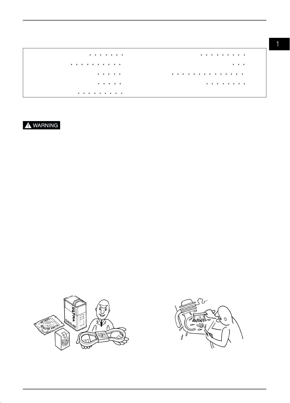
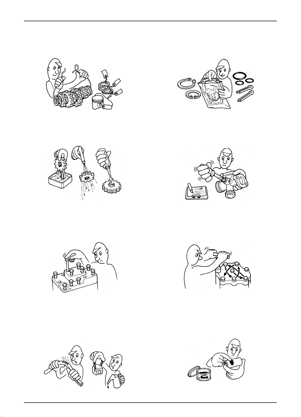
1. Parts and lubrication oil must be DAELIM genuine or
recommended parts.
2. Before maintenance, remove deposit or dust from the
chasis.
Page 6
1-2
GENERAL INFORMATION
9. Check to see if the rubber part is worn out when
removing it and replace it if necessary. Some rubber part
is weak to gasoline and kerosene, so pay attention not to
soak with gasoline or oils.
10. Recommended grease must be applied to or filled in
the specified place.
7. Align the bolts to uniform the tightening points before
tightening them when you don’t know the bolt length.
8. Bolts, nuts and pieces must be tightened from the bigger
diameter to the smaller one, from inside to outside and
diagonally with the specified torque.
5. Clean the parts after the overhaul and before the test and
remove the cleaning oil with compressed air. Apply oil
to seal face during installation.
6. Check necessary place and measure necessary data
during installation. When installing, return to the state
before removing.
3. Store the parts of each system discriminatively to install
each part in the right place.
4. After removing gasket, O-ring, piston pin clip and cotter
pin, always replace them with the new one. When
removing the snap ring, it can be easily missed after
transformation or installation.
Page 7
1-3
GENERAL INFORMATION
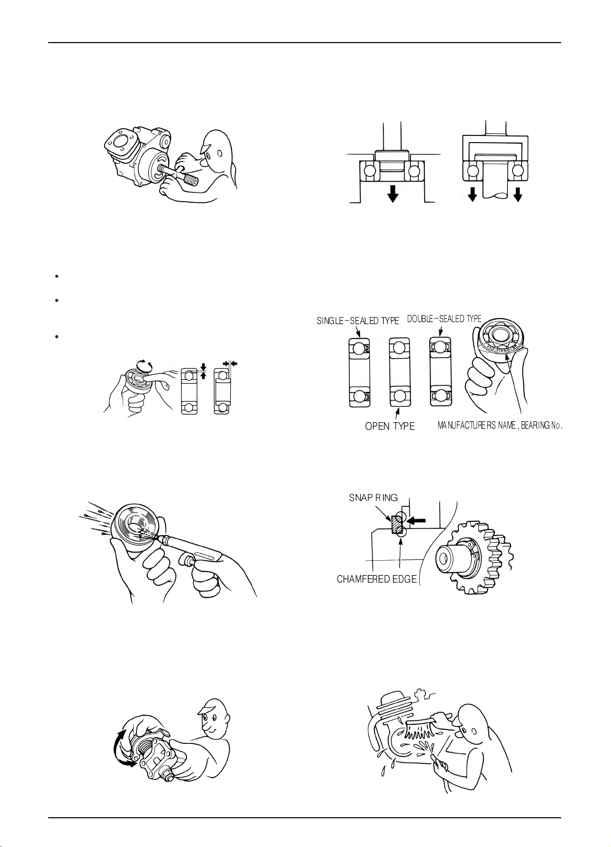
11. Maintenance needed to use the specialized tools must
be performed with the right tool.
12. Never reuse the ball bearing removed with the ball
applied pressure when removing press-fitted the
bearing.
13. Check the smooth rotation of inner or outer race of the
ball bearing by rotating it manually.
Replace the ball bearing having excessive axial/
longitudinal hanging.
Wipe the ball bearing likely to have hanging with
cleaning oil.(except double-sided sealed type ball
bearing)
Replace the ball bearing of which press-fitted part is
slacked at the case or shaft.
14. Pay attention to installation direction in case of the
single-sided sealed ball bearing. Install the opendirection or double-sided sealed bearing in the way
that the face marked with manufacturer and size
should direct to the outer axle.
15. When blowing the ball bearing with compressed air
after cleaning, keep the race from rotating. High speed
rotation of the race may damage the bearing. Prior to
installation, apply oil or grease to the bearing.
16. Install the snap ring so that chamfered side directs to
the load-applied side. After installation, check the
proper installation by rotating the snap ring.
17. Check each part for proper tightening and operation
after installation.
18. The brake fluid and coolant can damage the painted
plastic or rubber parts. Keep these parts from
contacting with them and wash these parts with water
in case of contact.
’
Page 8
1-4
GENERAL INFORMATION
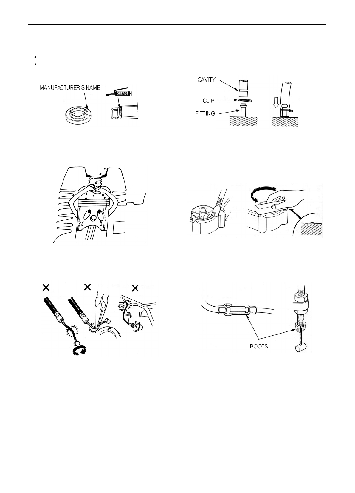
21. Keep the pneumatic system interior or the engine
interior from the infiltration of dust.
22. Install the gasket mounted in the contact surface of
each case of the engine while removing gasket
material completely. Remove damaged contact surface
by wiping with the oil stone equally.
19. Install the oil seal so that the manufacturer marked
surface directs outer surface.(direction not covered
with oil)
Pay attention not to bend or damage the lip.
Apply the grease to the lip.
20. Connect the tube until the tube fully inserted in the
joint. Install the clip if it is supplied. Replace the tube
having slacked end.
23. Pay attention not to bend the cable excessively.
Transformed or damaged cable may cause malfunction
or damage.
24. Install the boots with the installing groove by inserting
the boots into the groove.
’
Page 9
1-5
GENERAL INFORMATION
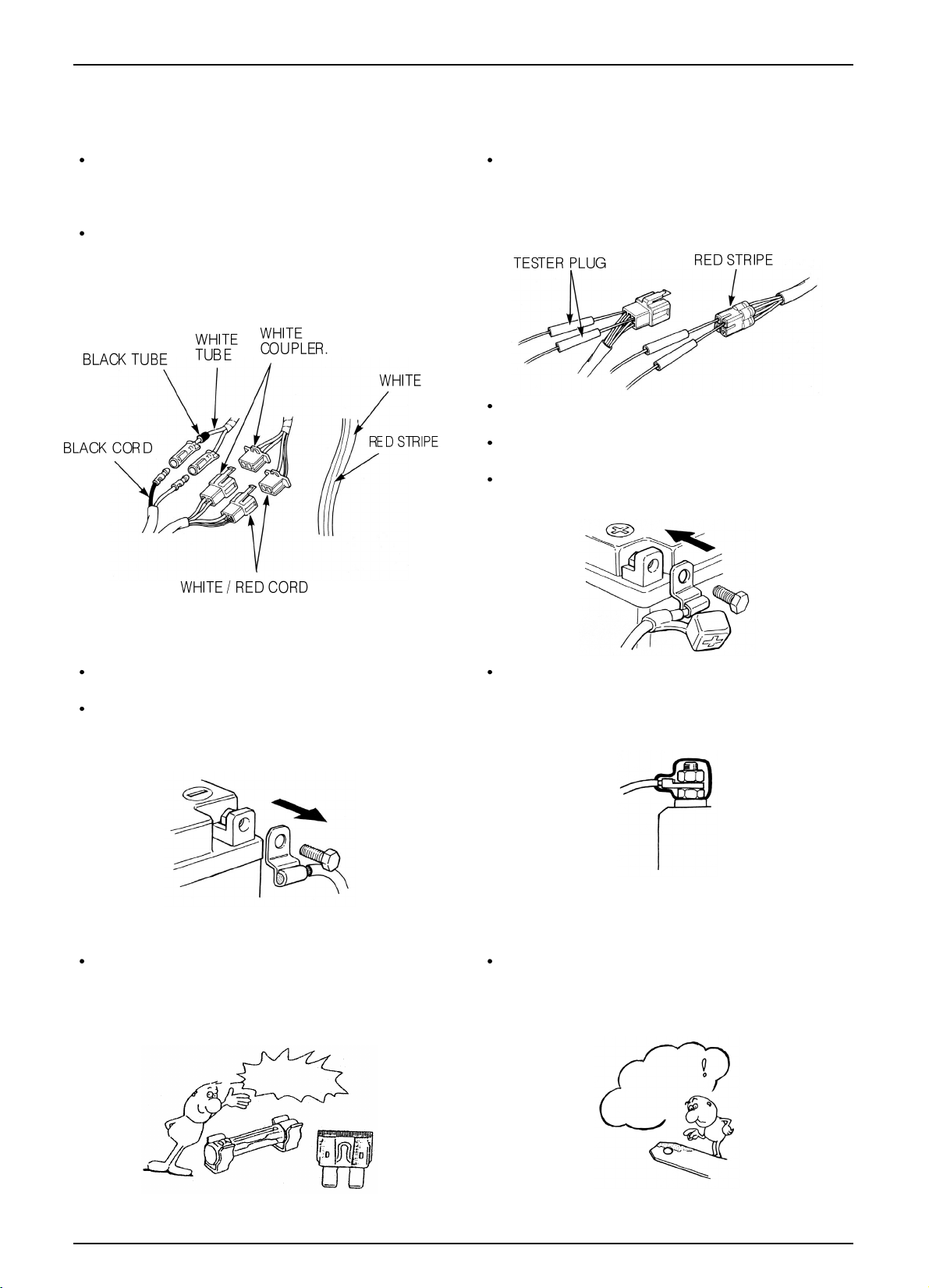
Each cord must be connected depending on its color.
When connecting different cord, attach color tube
around the connector. Connect the coupler to the
connector with same color and same pin number.
Identify the two-colored cord by main color first and
then spriped color .
When measuring voltage or resistance of the cord
terminal using tester, contact the tester plug behind of
the coupler. Pay attention not to open the cord terminal
and contact the tester plug from the front of the coupler
in case of water-proof coupler.
Recheck the condition of contact, securing and
continuity of each part after maintenance.
When connecting the battery, the plus terminal must be
connected first.
After connecting the terminal, apply the grease to the
terminal.
When disconnecting the battery, the minus terminal
must be disconnected first.
Make sure that the tool such as spanner do not contact
with the frame.
Connect covers to the terminal after maintenance.
If the fuse is short-circuited, find out the cause and
repair. Replace with the fuse having the specified
capacity.
If there is rust in the terminal, remove the rust with sand
paper prior to connecting.
CAUTION WHEN WIRING
VALIDATION
OF CAPACITY!
REMOVE
THE
RUST!
Page 10
1-6
GENERAL INFORMATION
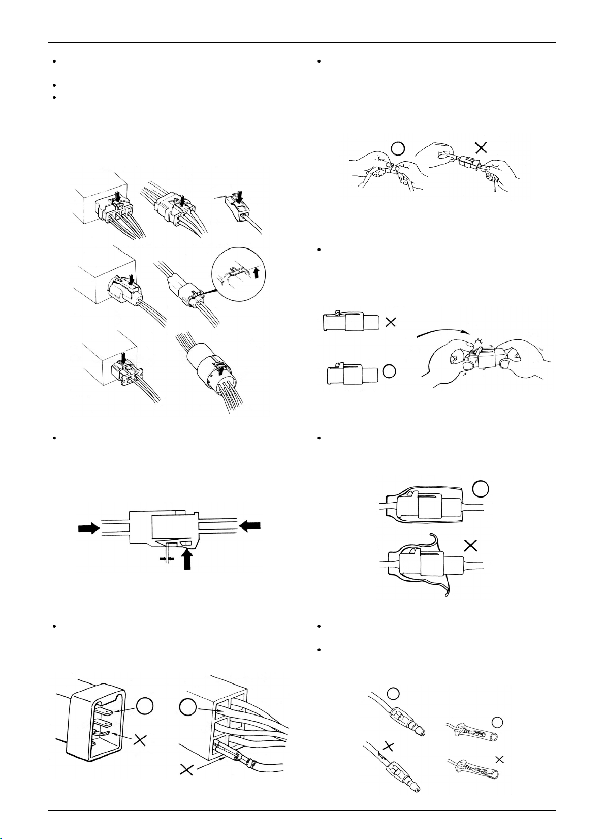
Insert the lock of the coupler until the lock is fully
secured.
Turn off the main switch before connecting/disconnecting.
Release the lock to disconnect the lock of the coupler.
The lock of the coupler has two types according to
releasing method(press type and pull type) so release it
properly according to the shape.
- Typical releasing method of the coupler is illustrated in
the following.
When disconnecting the coupler, disconnect it while
holding the coupler body. Pull while holding the wire
harness cord and do not remove the coupler connection.
Release the lock by inserting the coupler slightly and
then narrowing connection to remove the coupler.
Pay attention not to damage the vinyl cover of the
coupler.
Check to see if there is bended terminal and secure it to
avoid disconnecting.
If the wire harness coating is damaged, repair by
winding vinyl tape or replace it.
Prior to connecting the connector, make sure that the
cover is not damaged and the mess terminal is not
opened.
Page 11
1-7
GENERAL INFORMATION
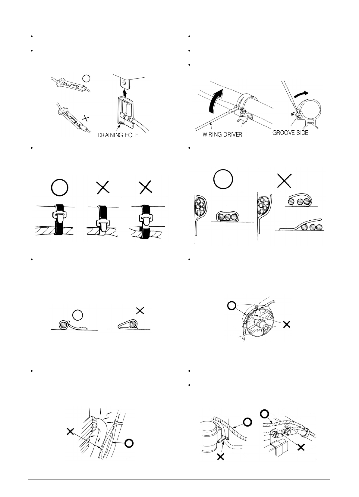
Wire band must be secured firmly in the specified
location of the frame. In case of aluminium band,
secure the wire harness to the coated part.
Secure the wire harness firmly using the clamp.
Insert the connector until the vinyl cover is fully
inserted into the terminal.
The opening of the vinyl cover must face at the ground
direction but in case of the plain connector, the draining
opening must face at the sky direction.
When removing T-start, broaden the groove of T-start
using the wiring driver and release the torque.
Connect the harness and the hose to T-start and then
insert until the groove is locked.
When removing T-start from the frame, replace it with
the new one.
In case of the weld clamp, do not clamp in the welded
part.
When clamping the wire harness, make sure that the
harness is not contacted with the shaft or rotating part.
When clamping the wire, pay attention not to contact
with hot part.
The wire harness must be routed without contacting
with the end of the lamp or any sharp edge.
The wire harness must be routed without contacting
with the end of the bolt or the piece.
Page 12
1-8
GENERAL INFORMATION
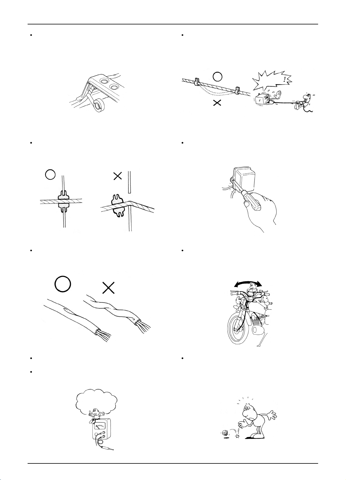
If necessary, lock the wire harness properly. When mounting parts, make sure that the wire harness
is not pressed by the parts.
In case that the wire harness is contacted with the end or
the sharp edge, protect both parts with tube or tape.
The wire must not hang down or be pulled excessively.
Do not twist the wire harness. Wire the wire harness not to be pulled or expanded
when the handle is turned to the right or the left
completely. Avoid excessive bending or chewing and
interference with the engine.
Prior to using the tester, please read the manual carefully and understand the contents.
When testing the resistance of the tester, the zero
adjustment must be performed before testing.
Do not drop or throw the parts especially
semiconductor contained parts because these parts may
be damaged by the impact of the drop.
NOT TO
PULL!
Is this
measurement range or
configuration in accord
with the manual?
Page 13
1-9
GENERAL INFORMATION
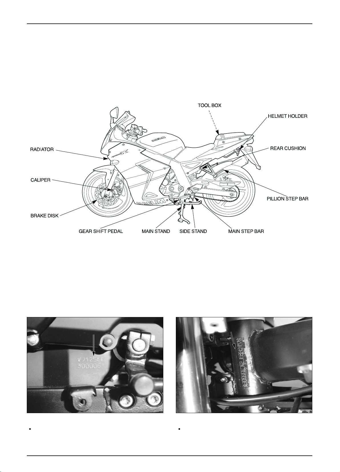
MODEL IDENTIFICATION
ENGINE SERIAL NUMBER LOCATION
The engine serial number is stamped on left crankcase.
FRAME SERIAL NUMBER LOCATION
The frame serial number is stamped on the left side of
steering head.
FRAME SERIAL NUMBER
FRAME SERIAL NUMBER
FRAME SERIAL NUMBER
FRAME SERIAL NUMBER
FRAME SERIAL NUMBER
FRAME SERIAL NUMBER
FRAME SERIAL NUMBER
FRAME SERIAL NUMBER
FRAME SERIAL NUMBER
FRAME SERIAL NUMBER
FRAME SERIAL NUMBER
FRAME SERIAL NUMBER
FRAME SERIAL NUMBER
FRAME SERIAL NUMBER
ENGINE SERIAL NUMBER
ENGINE SERIAL NUMBER
ENGINE SERIAL NUMBER
ENGINE SERIAL NUMBER
ENGINE SERIAL NUMBER
ENGINE SERIAL NUMBER
ENGINE SERIAL NUMBER
ENGINE SERIAL NUMBER
ENGINE SERIAL NUMBER
ENGINE SERIAL NUMBER
ENGINE SERIAL NUMBER
ENGINE SERIAL NUMBER
ENGINE SERIAL NUMBER
ENGINE SERIAL NUMBER
Page 14
1-10
GENERAL INFORMATION
SPECIFICATIONS
ITEM SPECIFICATIONS
OVERALL LENGTH 2,025mm
OVERALL WIDTH 764mm
OVERALL HEIGHT 1,180mm
DIMENSIONS
WHEEL BASE 1,380mm
SEAT HEIGHT 780mm
GROUND CLEARANCE 139mm
DRY WEIGHT 162kgf
CURB WEIGHT 292kgf
TYPE Double Cradle
FRONT SUSPENSION / STROKE Telescopic / 130mm
REAR SUSPENSION / STROKE Swingarm / 28mm
FRONT TIRE SIZE (TYPE) 110/70-17 54P (Tubeless)
REAR TIRE SIZE (TYPE) 140/60-17 69P (Tubeless)
TIRE PRESSURE 1 PERSON FRONT
2.00kgf/cm2(200kPa)
REAR 2.00kgf/cm
2
(200kPa)
FRAME 2 PERSON FRONT
2.00kgf/cm2(200kPa)
REAR 2.25kgf/cm
2
(225kPa)
FRONT BRAKE Hydraulic Disk
REAR BRAKE Hydraulic Disk
FUEL CAPACITY 14.85
FUEL RESERVE CAPACITY 4.0
CASTER ANGLE 25.2
TRAIL 93.5mm
FRONT FORK OIL CAPACITY 265
2.5cc
TYPE Liquid 4-stroke DOHC(4 Valve)
CYLINDER NUMBER, ARRANGEMENT
1 Cylinder, 20 Inclined from vertical
BORE AND STROKE 56.5 X 49.5mm
DISPLACEMENT 124.1cm
3
COMPRESSION RATIO 11.8:1
VALVE TRAIN DOHC Chain Drive
OIL CAPACITY 1.5
After Disassembly
1.35 After Draining and Oil Filter Change
ENGINE
1.3 After Draining
LUBRICATION SYSTEM Wet Pressing and Spray
AIR FILTRATION TYPE Paper Filter
CYLINDER COMPRESSION 13.0kgf/cm
2
(600rpm)
INTAKE VALVE OPEN 23
BTDC
CLOSED 55
ABDC (1.12mm Lift)
EXHAUST VALVE OPEN 66.3
BBDC
CLOSED 23.6
ATDC (1.12mm Lift)
VALVE CLEARANCE INTAKE 0.15
0.02mm
(A COOLING-OFF PERIOD)
EXHAUST 0.20 0.02mm
ENGINE DRY WEIGHT 32.0kgf
Page 15
1-11
GENERAL INFORMATION
ITEM SPECIFICATIONS
CLUTCH TYPE Multiplate Wet Clutch / 5
TRANSMISSION TYPE Constant Mesh
GEAR RATIO 1st 3.200(37/12 T)
DRIVE TRAIN
GEAR RATIO 2nd 2.143(32/17 T)
GEAR RATIO 3rd 1.438(29/21 T)
GEAR RATIO 4th 1.095(23/21 T)
GEAR RATIO 5th 0.923(24/26 T)
GEARSHIFT PATTERN Left foot operated return system
Down 1-N-2-3-4-5 Up
IGNITION TYPE Full Transisterized
IGNITION TIMING “F” MARK 18 BTDC / 1,600(rpm)
FULL ADVANCE 30 BTDC / 8,500(rpm)
AC GENERATOR 12V-17A/5,000(rpm)
BATTERY CAPACITY 12V 10AH
SPARK PLUG CR9EH -9
SPARK PLUG GAP 0.8 - 0.9mm
FUSE CAPACITY 30A
STARTING SYSTEM Starter Motor
ELECTRICAL
HEADLIGHT (HIGH/LOW BEAM) 55W/55W
POSITION LAMP 5W
TURN SIGNAL LAMP 10W 4
STOP/TAIL LIGHTS 21W/5W
SPEEDOMETER LAMP 3W
NEUTRAL INDICATOR LAMP LED 1
HIGH BEAM INDICATOR LAMP LED
WINKER INDICATOR LAMP LED
LICENCE PLATE LAMP 5W
TACHOMETER LAMP LED 1
MALFUNCTION INDICATOR LAMP LED
Page 16
1-12
GENERAL INFORMATION
TORQUE VALUES
ENGINE
FRAME
kgf.m,(N.m)
TORQUE
TORQUE
kgf.m,(N.m)
REFERENCE
THREAD DIA
(mm)
Q’TY
ITEM
REFERENCE
THREAD DIA
(mm)
Q’TY
ITEM
8
4
4
1
2
1
1
1
1
3
2
3
1
2
12
1
7
1
1
10
1
1
1
1
M6 1.0
M10
1.25
M6
1.0
M6
1.0
M6
1.0
M6
1.0
M16
1.0
M16
1.0
M12
1.25
M8
1.25
M6
1.0
M10
1.25
M6
1.0
M6
1.0
M6
1.0
M6
1.0
M6
1.0
M14
1.5
M30
1.5
M6
1.0
M10
1.25
M6
1.0
M36
1.5
M12
1.25
Apply Engine Oil
Apply Engine Oil
Apply Engine Oil
Apply Engine Oil
Apply Engine Oil
Remove negative screw
Remove negative screw
1.0~1.2
3.5~4.5
0.8~1.2
0.8~1.2
1.0~1.4
0.35~0.5
6.0~7.0
6.0~7.0
5.0~6.0
3.0~3.4
1.0~1.4
1.0~1.4
1.0~1.4
1.0~1.4
1.0~1.2
1.0~1.2
1.0~1.2
0.4~0.8
1.0~2.0
1.0~1.2
1.0~1.2
1.0~1.4
1.0~2.0
1.0~2.0
CAM HOLDER BOLT(SHBOLT)
CYLINDER HEAD SPECIAL SOCKET NUT
CYLINDER HEAD COVER BOLT
CAM CHAIN TENSIONER PIVOT BOLT
CAM CHAIN TENSIONER LIFTER BOLT
CAM CHAIN TENSIONER LIFTER SCREW
PRIMARY DRIVE GEAR NUT
CLUCH LOCK NUT
FLYWHEEL BOLT
STARTER CLUTCH SOCKET BOLT
BEARING SET PLATE BOLT
OIL FILTER COVER SOCKET BOLT
SHIFT DRUM STOPPER ARM BOLT
DRIVE SPROCKET BOLT
R.CRANKCASE COVER BOLT
OIL FILTER COVER BOLT
L.CRANKCASE COVER BOLT
A.C GENERATOR CAP
CRANKSHAFT HOLE CAP
CRANKCASE BOLT
SPARK PLUG
START MOTOR NUT
TAPPET ADJUST HOLE CAP
ENGIN TEMPERATURE SENSOR
1
1
2
4
2
1
1
1
1
4
2
M10
1.25
M10
1.25
M10
1.25
M8 1.25
M8
1.25
M10
1.25
M10 1.25
M 5
0.8
M14
1.5
M10
1.25
M10
1.25
HEX NUT
U- NUT
U- NUT
4.5~5.5
5.0~6.0
4.5~5.5
2.4~3.0
2.4~3.0
1.0~2.0
4.0~5.0
0.35~0.5
8.0~10.0
5.5~6.5
3.4~4.0
REAR ENGIN HANGER BOLT(UPPER)
REAR ENGIN HANGER BOLT(UNDER)
FRONT ENGIN HANGER BOLT(UPPER/UNDER)
FRONT ENGIN HANGER PLATE BOLT
STEERING HANDLE PIPE BOLT
SIDE STAND PIVOT SCREW
SIDE STAND PIVOT NUT
SPEEDOMETER GEAR BOX SCREW
REAR AXLE NUT
DRIVE SPROKET NUT
REAR BRAKE OIL BOLT
Page 17
TORQUE
1-13
GENERAL INFORMATION
REFERENCE
THREAD DIA
(mm)
Q’TY
ITEM
*Torque specifications listed above are for important fastener. Other should be tighten to the standard torque values below.
*SH(Small Head) : It describe 6mm bolt of 8mm flange bolt.
TYPE
TORQUE
TYPE
TORQUE
kgf mNm kgf mNm
15mm BOLT, NUT 4.0~6.0 0.45~0.6 5mm SCREW 3.4~5.0 0.35~0.5
16mm BOLT, NUT 8~12 0.8~1.2
6mm SCREW, FLANGE BOLT
7~11 0.7~1.1
18mm BOLT, NUT 18~25 1.8~2.5
6mm FLANGE BOLT, NUT
9.8~14 1.0~1.4
10mm BOLT, NUT 29~39 3.0~4.0
8mm FLANGE BOLT, NUT
24~29 2.4~3.0
12mm BOLT, NUT 49~59 5.0~6.0
10mm FLANGE BOLT, NUT
34~44 3.5~4.5
(Include SH type)
kgf.m,(N,m)
FRAME
2
2
1
6
4
4
2
1
1
2
2
2
1
2
2
4
2
5
M8
1.25
M6
1.0
M14
1.5
M8
1.25
M10
1.25
M8
1.25
M6
1.0
M22
1.0
M22
1.0
M8
1.25
M8
1.25
M8
1.25
M14
1.25
M10
1.25
6mm Tapping
M8
1.25
M8
1.25
M8
1.25
U- NUT
U- NUT
2.8~3.4
1.0~1.4
5.5~6.5
4.0~4.5
3.0~4.0
2.8~3.4
1.0~1.4
6.0~9.0
0.25~0.35
2.4~3.0
3.0~4.0
2.4~3.0
8.0~10.0
3.5~4.5
0.5~0.7
4.0~4.5
1.8~2.5
4.0~4.5
REAR CALIPER BRACKET BOLT
REAR MASTER CYLINDER HOLDER SOCKET BOLT
FRONT AXLE NUT
FRONT BRAKE DISK BOLT
BRAKE OIL BOLT (FRONT/REAR)
CALIPER BRACKET BOLT (FRONT/REAR)
FRONT MASTER CYLINDER HOLDER BOLT
STEERING STEM NUT
STEERING TOP THREAD
FORK TOP BRIDGE PINCH BOLT
BOTTOM BRIDGE PINCH BOLT
FORK HANDLE PIPE MOUNTING BOLT
SWINGARM PIVOT NUT
REAR CUSHION UPPER/UNDER BOLT
CHAIN SLIDER SCREW
L. DOWNTUBE COMP ‘B’
HANDLE WEIGHT SOCKET BOLT
REAR BRAKE DISK SOCKET BOLT
Page 18
SYMBOL
1-14
GENERAL INFORMATION
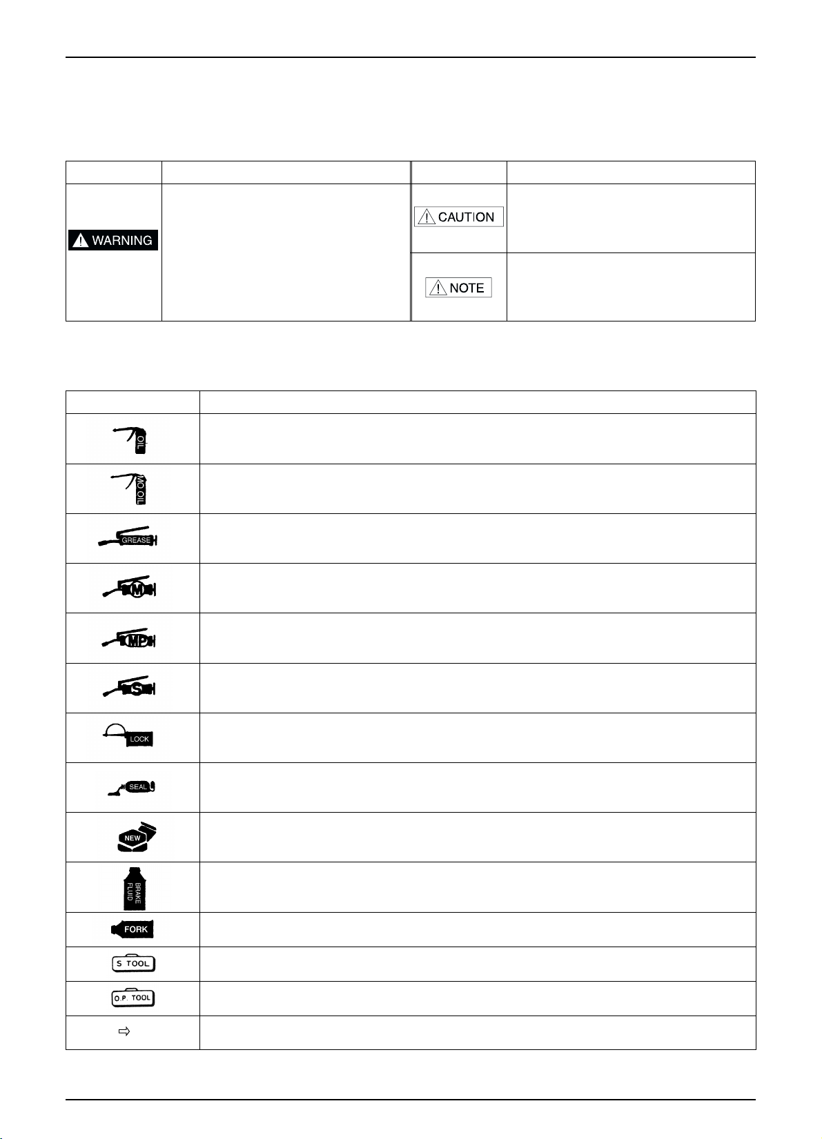
SYMBOLS / ABBREVIATIONS
The following symbols are used in this manual to represent job-related warnings or cautions.
MEANING
Indicates dangerous area. Serious
accident may result if instructions are not
followed.
MEANING
Indicates important work. Minor injury or
vehicle part damage may result if instruction
are not followed.
Indicates general safety matters. Provides
safety and appropriate handling procedures.
SYMBOL
SYMBOL
The following symbols indicate needed lubrication steps, the changing of parts, and required specialized tools, etc. when
performing maintenance.
CAUTION
Use option tool. These tools are obtained as you order parts.
Indicates reference page. (Example : Refer to page 3-1)
Use recommended engine oil, unless otherwise specified.
Use molybdenum oil solution (mixture of the engine oil and molybdenum grease with the ratio 1:1)
Use multi-purpose grease (Lithium based multi-purpose grease NLG #2 or equivalent)
Use molybdenum disulfide grease (containing more than 3% molybdenum disulfide, NLGI #2
or equivalent)
Use molybdenum disulfide paste containing more than 40% molybdenum disulfide, NLGI #2 or
equivalent)
Use silicone grease
Apply a locking agent. Use the agent of the middle strength, unless otherwise specified
Apply sealant
Replace the parts with new ones before assembly
Use brake fluid, DOT3 or DOT4. Use the recommended brake fluid, unless otherwise specified
Use Fork or Suspension Fluid
Use special tool
Special grease, etc. that do not correspond to the above are indicated without using symbols.
( 3-1)
Page 19
1-15
GENERAL INFORMATION
TOOLS
SPECIAL COMMON
DESCRIPTION REF. SEC. DESCRIPTION REF. SEC.
TESTER, GAUGE
COMPRESSION GAUGE
DIGITAL MULTI TESTER
PVA TESTER
BATTERY TESTER
TESTER RECORDER
2
17, 18
17, 18
18
5
DESCRIPTION REFERENCE SECTION REMARK
VALVE SEAT CUTTER
VALVE SEAT CUTTER 45
VALVE SEAT CUTTER 35
VALVE SEAT CUTTER 35
VALVE SEAT CUTTER 60
CUTTER HOLDER 5mm
10
10
10
10
10
24.5mm IN, EX
23mm IN
20mm EX
22mm IN, EX
Use with Valve Seat
DESCRIPTION REFERENCE SECTION REMARK
CLUTCH CENTER HOLDER 8
ACG ROTOR PULLER 9
VALVE GUIDE DRIVER 10
VALVE GUIDE REAMER 10
UNIVERSAL BEARING PULLER 12
BEARING REMOVER SET 12
THREAD ADAPTER 12
ASSEMBLY SHAFT 12
CRANK CASE ASSEMBLY COLOR 12
BALL RACE DRIVER 14
STEERING STEM DRIVER 14
FORK SEAL DRIVER 14
STEERING STEM SOCKET 14
SNAP RING PLIERS 16
WRENCH, 8
9mm 2
ADJUSTING WRENCH, B 2
LOCK NUT WRENCH, 20
24mm 6
EXTENSION BAR 8, 14
FLY WHEEL HOLDER 8, 9
VALVE SPRING COMPRESSOR 10
DRIVER 12, 14, 15
ATTACHMENT 12, 14, 15
PILOT 12, 14, 15
FORK SEAL DRIVER BODY 14
BEARING REMOVER HEAD 15
BEARING REMOVER SHAFT 15
LOCK NUT(M8) 10
Page 20
1-16
GENERAL INFORMATION
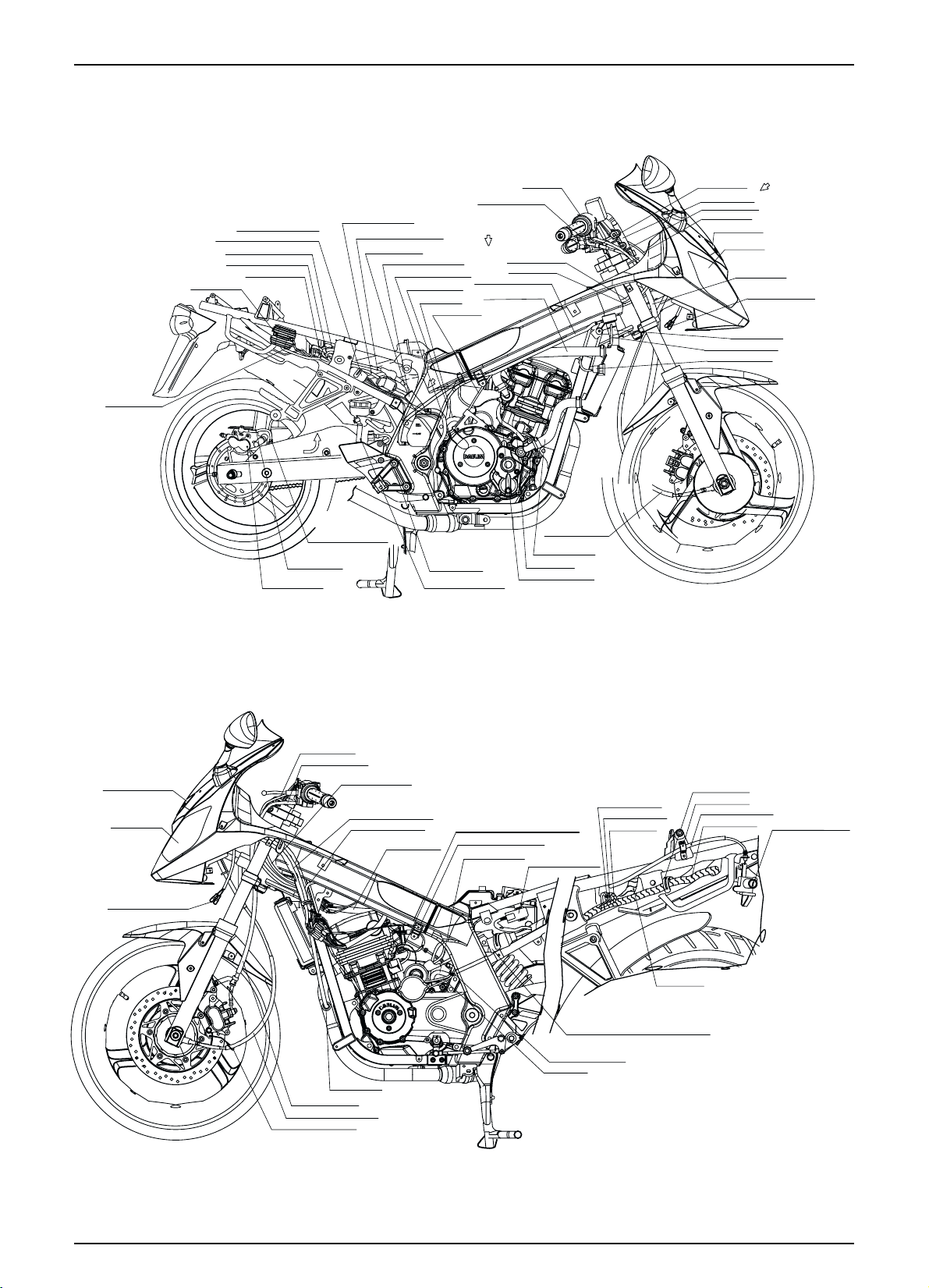
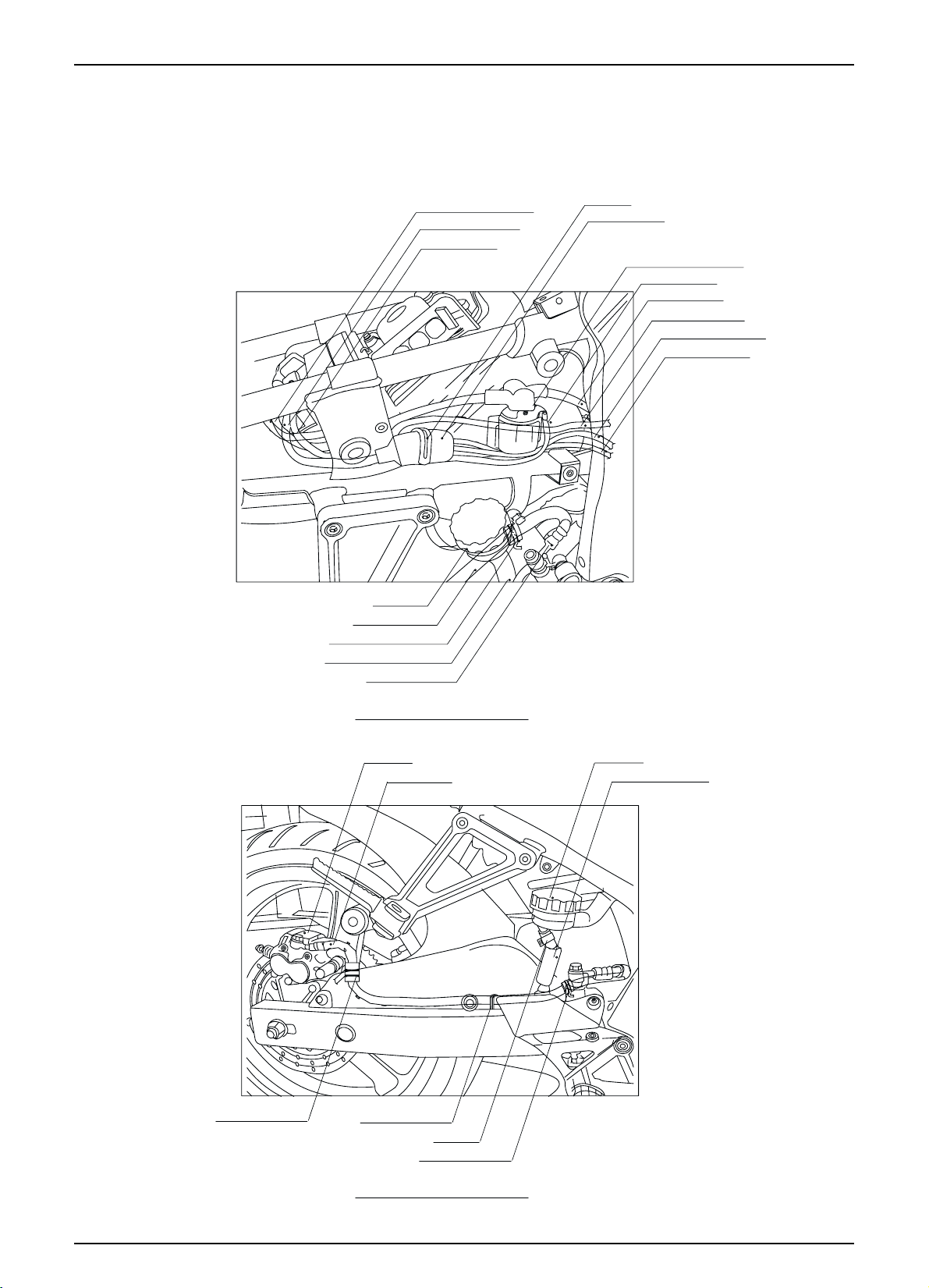
WIRING DIAGRAM
REG. EARTH WIRE
ST.-MAG SW.,RR. STOP SW.,
SIDE STAND SW. HARNESS COVER
ST.-MAG. BATTERY CABLE(+)
BATTERY EARTH CABLE
REG. RECTIFIER
ST.-MAG. SW. WIRE
A
RR. BRAKE HOSE
RR. CALIPER ASS'Y.
BATTERY EARTH CABLE
ST.-MAG. BATTERY CABLE(+)
ST.-MOTOR CABL E
RR. BRAKE HOSE CLAMP
RADIATOR RESERVE TANK
WATER PASS TUBE ASS'Y D
FUEL DRAIN TUBE
DRAIN TUBE
CLUTCH CABLE
B
RR. BRAKE HOSE
RR. BRAKE RESERVE TUBE
ST.-HAZ. SW.
*
‡“» »Œ 1.5»Œ ‚fi
D
ST.-HAZ. SW. CORD
CLUTCH CABLE
WATER PASS TUBE ASS'Y C
RADIATOR HOSE A
RADIATOR HOSE C
BY PASS TUBE
TEMPERATURE SENSOR
SPEEDOMETER CABLE
THROTTLE CABLE
FR. BRAKE HOSE
ST.-HAZ. SW. CORD
CLUTCH CABLE
POSITION LIGHT
HEAD LIGHT
FR. BRAKE HOSE
RADIATOR HOSE B
WA TER PASS TUBE ASS'Y.
THERMO SWITCH ASS'Y
C
RH. FR. WINKER CORD
POSITION LIGHT
HEAD LIGHT
LH. FR. WINKER CORD
CLUTCH CABLE
WINKER SW. CORD
THROTTLE CABLE
O2 SENSOR
FR.BRAKE HOSE
SPEEDOMETER CABLE
SPDMT. CABLE CLAMP
COMBI.METER CORD
O2 SENSOR WIRE
WIRE HARNESS
WA TER TEMPERATURE SENSOR
COMB. METER EARTH
BREATHER TUBE
HEAD LIGHT RELAY
ST.-MOTOR CABLE
ACG. CORD
BATT. + WIRE
BATT. - WIRE
ST.-MAG.
SW.√¯ WIRE
CABLE CLAMP
ECU WIRE
ACG., FUEL PUMP, GEAR POSITION,
CPS CORD HARNESS COVER
WIRE CLIP
SEAT LOCK CABLE
WIRE HARNESS
HELMET HOLDER
& SEAT LOCK ASS'Y.
Page 21
1-17
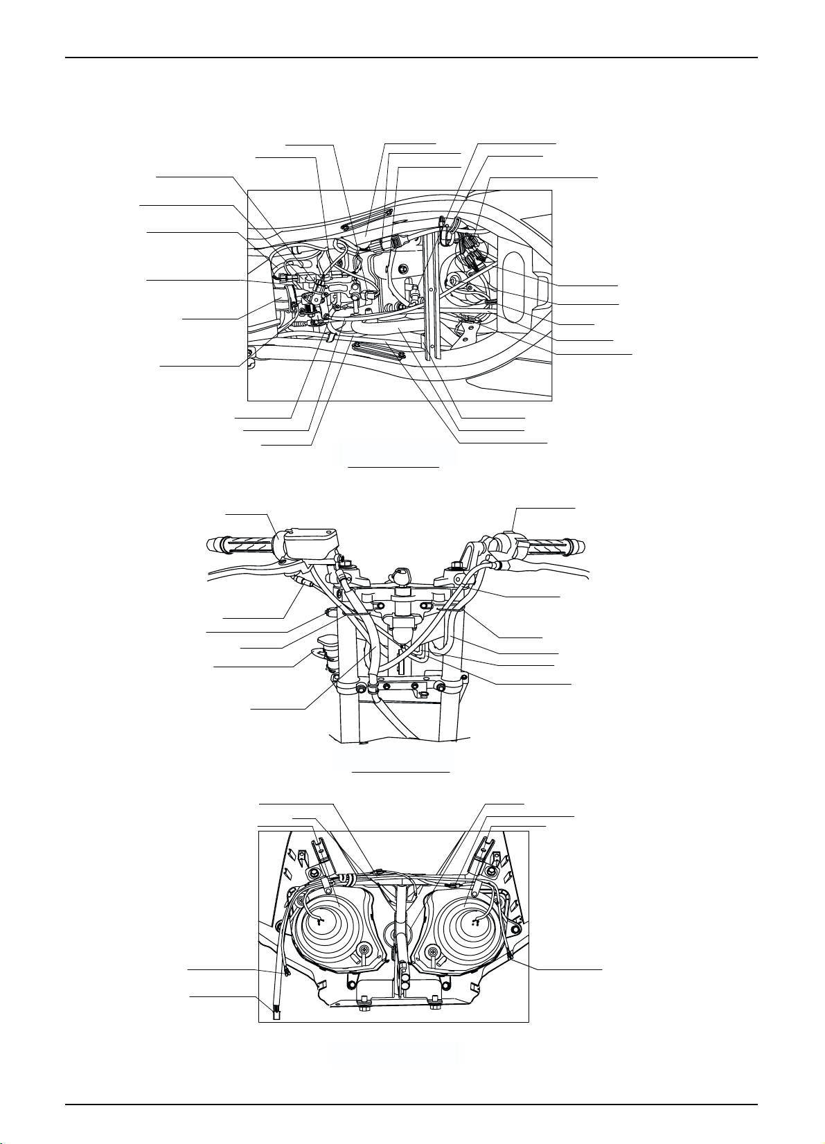
GENERAL INFORMATION
IDLE SPEED ACTUATOR
(ISA)
THROTTLE POSITION SENSOR
(TPS)
ST.-MAG. BATTERY CABLE(+)
WA TER TEMPERATURE SENSOR
CORD
CONN-TUBE
BATTERY EARTH CABLE
CLUTCH CABLE
THROTTLE CABLE
ST.-HAZ. SW.
FUEL INJECTOR
MAP & AT SENSOR
(MAPAT)
BY PASS TUBE
WIRE HARNESS
O2 SENSOR COUPLER
HIGH TENSION CORD
»”˛ »……(D)
DETAIL OF VIEW (D)
NOISE SUPPRESSOR CAP
IG. COIL EARTH
ST.-HAZ. SW.,COMB.& LOCK SW.,
WINKER SW.. ∞·º±
THROTTLE CABLE
FAN MOTOR ASS'Y
WIRE CLIP
CLUTCH CABLE
EMI. FILTER COUPLER
MOTOR EMI. FILTER
RADIATOR HOSE A
WATER PASS TUBE ASS'Y C
WINKER SW. CORD
THROTTLE CABLE
ST.-HAZ. SW. CORD
CABLE GUIDE
WATER PASS TUBE ASS'Y.
LH. FR. WINKER CORD
HEAD LIGHT COUPLER
FR. BRAKE HOSE
POSITION LIGHT COUPLER
HORN CORD
LH. HEAD LIGHT
DETAIL OF VIEW (C)
‚Ø”˛ »……(C)
CLUTCH CABLE
CABLE GUIDE
WINKER SW. CORD
THROTTLE CABLE
COMB.& LOCK SW. CORD
HORN COMP
RH. HEAD LIGHT COUPLER
RH. HEAD LIGHT
RH. FR. WINKER CORD
˙ ¶ ˘fi”˛ »……
DETAIL OF HEADLIGHT CASE PART
Page 22
1-18
GENERAL INFORMATION
RESERVE TANK
RR. BRAKE HOSE
RR. BRAKE HOSE GUIDE
RR. BRAKE RESERVE TUBE
RR. BRAKE HOSE
ST.-MAG. BATTERY CABLE(+)
ST.-MAG. SW. WIRE
BATTERY EARTH CABLE
WIRE CLIP
HARNESS COVER
ST.-MAG. BATTERY CABLE(+)
ST.-MAG. SW. ASS'Y.
ST.-MOTOR CABLE
BATTERY EARTH CABLE
SIDE STAND SW. CORD
RR. STOP SW. CORD
RR. BRAKE HOSE CLAMP
DETAIL OF VIEW (B)
RR. CALIPER
RR. BRAKE HOSE
RR. BRAKE HOSE GUIDE
RR. BRAKE HOSE GUIDE
RESERVE TANK
RR. BRAKE RESERVE TUBE
TUBE CLIP
DETAIL OF VIEW (A)
Page 23
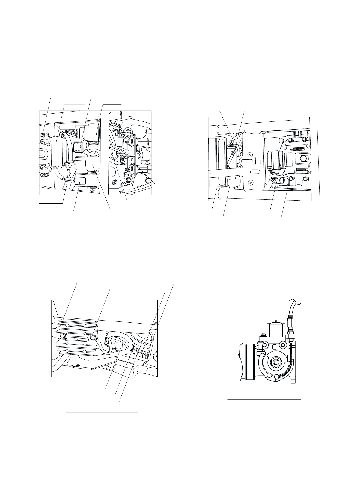
1-19
GENERAL INFORMATION
ECU COMP.
WIRE HARNESS
FUEL PUMP RELAY
SPARE FUSE(30A,15A)
FUSE BOX
WINKER RELAY
FUSE
DETAIL OF FUSE BOX PART
R/L.RR.WINKER CORD
FAN MOTOR RELAY
WIRE CLIP
BATTERY EARTH CABLE
BATT. BAND
BATTERY(12V 10AH MF.)
ST.-MAG.BATTERY CABLE(+)
ST.-MAG.BATTERY CORD(+)
ECU COMP. C OUPLER
ECU COMP. EARTH C OR D
DETAIL OF BATTER PART
REG. RECTIFIER
REG. EARTH WIRE
REG. RECTIFIER COUPLER
ST.-MAG. BATTERY CABLE(+)
BATTERY EARTH CABLE
DETAIL OF REGRECTIFIER PART
ST.-MAG. SW. WIRE
O2 SENSOR WIRE
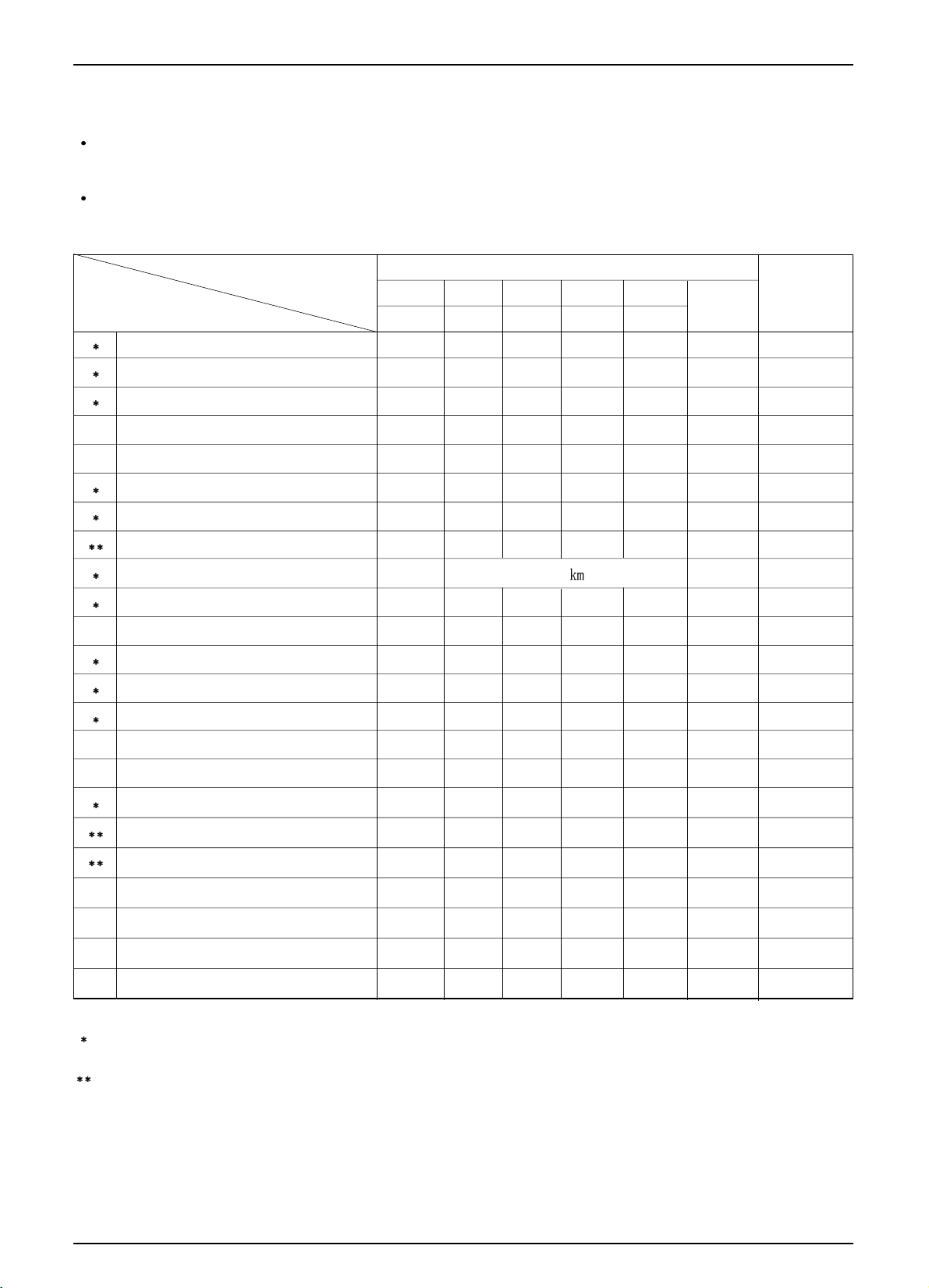
DETAIL OF THROTTLE BODY PART
Page 24

MEMO
Page 25
2-1
2. INSPECTIONS/ADJUSTMENTS
SERVICE INFORMATION
The exhaust gas contains poisonous substance. Do not keep engine idling in a closed or poorly ventilated place for a
long period of time.
SPECIFICATIONS
TIRES
SERVICE INFORMATION 2-1
MAINTENANCE SCHEDULE 2-3
FUEL LINE (FUEL TUBE) 2-4
THROTTLE GRIP OPERATION
2-4
AIR CLEANER
2-5
SPARK PLUG
2-6
VALVE CLEARANCE
2-6
CYLINDER COMPRESSION PRESSURE
2-7
DRIVE CHAIN
2-8
DRIVE CHAIN SLIDER
2-10
BRAKE FLUID
2-10
BRAKE PAD WEAR
2-10
BRAKE SYSTEM
2-11
BRAKE STOP SWITCH
2-12
HEADLIGHT AIM
2-12
CLUTCH SYSTEM
2-12
SIDE STAND
2-13
SUSPENSION
2-14
BOLTS, NUTS, FASTENERS
2-14
WHEEL/TIRE
2-15
STEERING STEM
2-15
COOLANT LEVEL INSPECTION
2-16
COOLANT REPLACEMENT
2-16
THROTTLE GRIP PLAY 2~6mm
SPARK PLUG CR9EH-9
SPARK PLUG GAP 0.8~0.9mm
IN. 0.15mm
EX. 0.20mm
CYLINDER COMPRESSION 13.0kgf/
( 600rpm )
DRIVE CHAIN SLACK 10~20mm
REAR BRAKE PEDAL FREE PLAY 10~20mm
CLUTCH LEVER FREE PLAY 10~20mm
For information on engine oil and oil filter, refer to sections 3-3 and 3-4.
Stand the main stand prior to beginning work.
VALVE CLEARANCE
COLD TIRE
PRESSURE
TIRE SIZE
DRIVER ONLY
DRIVER AND A
PASSENGER
FRONT
REAR
FRONT
REAR
FRONT
REAR
FRONT
REAR
2.00kgf/
(200kPa, 29psi )
2.00kgf/ (200kPa, 29psi )
2.00kgf/
(200kPa, 29psi )
2.25kgf/
(225kPa, 32psi )
110/70-17 54P
140/60-17 60P
5.5mm
7.0mm
TIRE PART MINIMUM-DEPTH
Page 26

2-2
TORQUE VALUES
SPARK PLUG 1.1 kgf-m( 11N.m)
CYLINDER HEAD COVER BOLT 1.0 kgf-m( 10N.m)
AC GENERATOR CAP 0.6 kgf-m( 6N.m)
CRANKSHAFT HOLE CAP 0.8 kgf-m( 8N.m)
AIR CLEANER CASE COVER SCREW 0.43kgf-m(4.3N.m)
REAR AXLE NUT 8.8kgf-m(88N.m)
DRIVE SPROCKET BOLT 1.2kgf-m(12N.m)
DRIVEN SPROCKET NUT 5.9kgf-m(59N.m)
TOOLS
WRENCH, 8 9 mm
COMPRESSION GAUGE
INSPECTIONS / ADJUSTMENTS
Page 27
2-3
INSPECTIONS / ADJUSTMENTS
MAINTENANCE SCHEDULE
Perform the Self Inspections Before Operation at each scheduled maintenance period.
I : INSPECT AND CLEAN, ADJUST, LUBRICATE OR REPLACE IF NECESSARY.
R : REPLACE L : LUBRICATE C : CLEAN
These instructions are based on the assumption that the motorcycle will be used exclusively for its designed purpose.
Sustained high speed operation, or operation in unusually wet or dusty conditions, will require more frequent service
than specified in the following chart.
If you do not have the appropriate tools or information to conduct maintenance, or if you feel you are not capable to
perform maintenance on this vehicle, contact authorized dealers or repair shops for maintenance and repairs.
To ensure safety, inspections and maintenance of these parts must be carried out by dealers, or repair centers.
NOTES :
(1) At higher odometer readings, repeat at the frequency interval established here.
(2) Service more frequently when riding in unusually wet or dusty areas.
(3) Replace every 2 years, or at indicated odometer interval, whichever comes first. Replacement requires
mechanical skill.
FUEL LINE
FUEL FILTER
THROTTLE GRIP OPERATION
AIR CLEANER ELEMENT
SPARK PLUG
VALVE CLEARANCE
ENGINE OIL
ENGINE OIL FILTER ELEMENT
DRIVE CHAIN
BRAKE FLUID
BRAKE /PAD WEAR
BRAKE SYSTEM
BRAKE STOP SWITCH
HEADLIGHT AIM
CLUTCH SYSTEM
SIDE STAND
SUSPENSION
BOLTS, NUTS, FASTENERS
WHEELS/TIRES
STEERING HANDLE BEARING
RADIATOR COOLANT
RADIATOR CORE
RADIATOR CAP
I
R
R
I
I
I
I
I
I
I
I
R
I
R
I
I
R
R
I
I
I
I
I
I
I
I
I
I
I
I
I
R
I
R
R
I
R
R
I
I
I
I
I
I
I
I
I
I
I
R
I
I
I
R
I
R
I
I
R
R
I
I
I
I
I
I
I
I
I
I
I
2-4
2-4
2-4
2-5
2-6
2-6
3-3
3-4
2-8
2-10
2-10
2-11
2-12
2-12
2-12
2-12
2-14
2-14
2-15
2-15
6-3
6-5
6-6
NOTE (2)
NOTE (3)
Every 1,000
: I and L
FREQUENCY
ODOMETER READING(NOTE 1)
61218
1 4 8 12 REMARK
ITEM
x 1000Km
MONTH
REFER TO
PAGE
Page 28
2-4
INSPECTIONS / ADJUSTMENTS
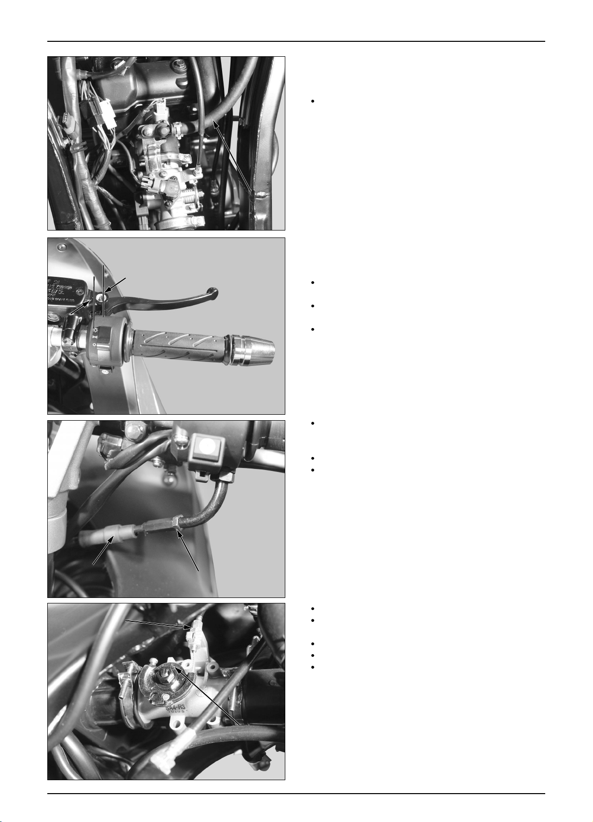
FUEL LINE (FUEL TUBE)
Check the fuel tube for deterioration, damage or
leakage. Replace it if necessary.
THROTTLE GRIP OPERATION
Check if the throttle grip operates smoothly in all
steering positions.
If not operating smoothly, check the deterioration,
damage and kink of the throttle cable.
Measure the free play at the throttle grip.
FREE PLAY : 2~6mm
Throttle grip free play can be adjusted at either end of
the throttle cable.
Minor adjustment are made with the upper adjuster.
Adjust the free play by loosening the lock nut and
turning the adjuster.
FUEL TUBE
FUEL TUBE
FUEL TUBE
FUEL TUBE
FUEL TUBE
FUEL TUBE
FUEL TUBE
FUEL TUBE
FUEL TUBE
FUEL TUBE
FUEL TUBE
FUEL TUBE
FUEL TUBE
FUEL TUBE
FUEL TUBE
FUEL TUBE
FUEL TUBE
FUEL TUBE
2~6mm
2~6mm
2~6mm
2~6mm
2~6mm
2~6mm
2~6mm
2~6mm
2~6mm
2~6mm
2~6mm
2~6mm
2~6mm
2~6mm
2~6mm
2~6mm
2~6mm
2~6mm
ADJUSTER
ADJUSTER
ADJUSTER
ADJUSTER
ADJUSTER
ADJUSTER
ADJUSTER
ADJUSTER
ADJUSTER
ADJUSTER
ADJUSTER
ADJUSTER
ADJUSTER
ADJUSTER
ADJUSTER
ADJUSTER
ADJUSTER
ADJUSTER
ADJUSTER
ADJUSTER
ADJUSTER
ADJUSTER
ADJUSTER
ADJUSTER
ADJUSTER
ADJUSTER
ADJUSTER
ADJUSTER
ADJUSTER
ADJUSTER
ADJUSTER
ADJUSTER
ADJUSTER
ADJUSTER
ADJUSTER
ADJUSTER
LOCK NUT
LOCK NUT
LOCK NUT
LOCK NUT
LOCK NUT
LOCK NUT
LOCK NUT
LOCK NUT
LOCK NUT
LOCK NUT
LOCK NUT
LOCK NUT
LOCK NUT
LOCK NUT
LOCK NUT
LOCK NUT
LOCK NUT
LOCK NUT
LOCK NUT
LOCK NUT
LOCK NUT
LOCK NUT
LOCK NUT
LOCK NUT
LOCK NUT
LOCK NUT
LOCK NUT
LOCK NUT
LOCK NUT
LOCK NUT
LOCK NUT
LOCK NUT
LOCK NUT
LOCK NUT
LOCK NUT
LOCK NUT
Major adjustments are made with the lower adjuster.
Adjust the free play by loosening the lock nut and
turning the adjuster.
After adjustment, tighten the lock nut securely.
Recheck the throttle operation.
Replace any damaged parts, if necessary.
Page 29
2-5
INSPECTIONS / ADJUSTMENTS
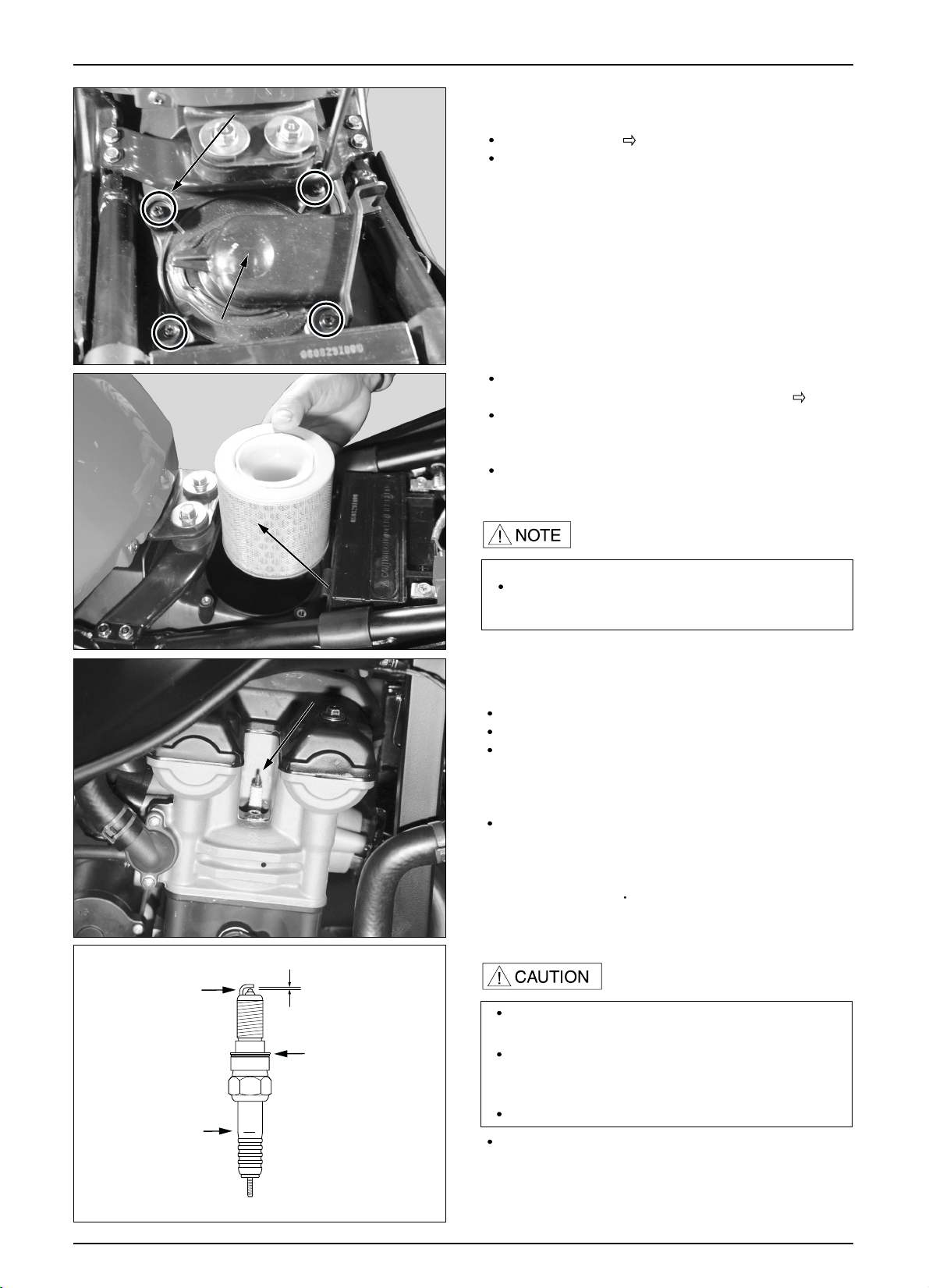
AIR CLEANER
Remove the seat. ( 13-2)
Loosen the 4 screws, remove the air cleaner housing
cover.
Remove and discard the air cleaner element in
accordance with the maintenance schedule. (
2-3)
Also replace the air cleaner element any time it is
excessively dirty or damage.
Install in the reverse order of removal.
Do not reuse the air cleaner element to clean by
compressed air.
SCREWS
SCREWS
SCREWS
SCREWS
SCREWS
SCREWS
SCREWS
SCREWS
SCREWS
SCREWS
SCREWS
SCREWS
SCREWS
SCREWS
SCREWS
SCREWS
SCREWS
SCREWS
AIR CLEANER
HOUSING COVER
AIR CLEANER
HOUSING COVER
AIR CLEANER
HOUSING COVER
AIR CLEANER
HOUSING COVER
AIR CLEANER
HOUSING COVER
AIR CLEANER
HOUSING COVER
AIR CLEANER
HOUSING COVER
AIR CLEANER
HOUSING COVER
AIR CLEANER
HOUSING COVER
AIR CLEANER
HOUSING COVER
AIR CLEANER
HOUSING COVER
AIR CLEANER
HOUSING COVER
AIR CLEANER
HOUSING COVER
AIR CLEANER
HOUSING COVER
AIR CLEANER
HOUSING COVER
AIR CLEANER
HOUSING COVER
AIR CLEANER
ELEMENT
AIR CLEANER
ELEMENT
AIR CLEANER
ELEMENT
AIR CLEANER
ELEMENT
AIR CLEANER
ELEMENT
AIR CLEANER
ELEMENT
AIR CLEANER
ELEMENT
AIR CLEANER
ELEMENT
AIR CLEANER
ELEMENT
AIR CLEANER
ELEMENT
AIR CLEANER
ELEMENT
AIR CLEANER
ELEMENT
AIR CLEANER
ELEMENT
AIR CLEANER
ELEMENT
AIR CLEANER
ELEMENT
AIR CLEANER
ELEMENT
AIR CLEANER
ELEMENT
AIR CLEANER
ELEMENT
SPARK PLUG
Remove the spark plug cap.
Check the plug for damage, contamination or deposits.
If the spark plug is severely contaminated or damaged,
raplace with a new one. If the plug can be reused after
removing only the carbon, use plug cleaner and wire
brush to clean the plug.
Always use a feeler gauge to check the gap.
GENUINE PLUG : CR9EH-9
SPARK PLUG GAP : 0.8~0.9mm
TORQUE : 1.1kgf
m
Assemble the spark plug.
Make sure there is no dirt or debris on the seat of the
spark plug hole before inserting the spark plug.
To prevent damage to the cylinder head, handtighten
the spark plug before using a wrench to tighten to the
specified torque.
Do not overtighten the spark plug.
0.8~0.9mm
CHECK GAP,
DEPOSITS
CHECK FOR
CRACKS
CHECK WASHER
FOR DAMAGE
SPARK PLUG
SPARK PLUG
SPARK PLUG
SPARK PLUG
SPARK PLUG
SPARK PLUG
SPARK PLUG
SPARK PLUG
SPARK PLUG
SPARK PLUG
SPARK PLUG
SPARK PLUG
SPARK PLUG
SPARK PLUG
SPARK PLUG
SPARK PLUG
Page 30
FEELER GAUGE
FEELER GAUGE
FEELER GAUGE
FEELER GAUGE
FEELER GAUGE
FEELER GAUGE
FEELER GAUGE
FEELER GAUGE
FEELER GAUGE
FEELER GAUGE
FEELER GAUGE
FEELER GAUGE
FEELER GAUGE
FEELER GAUGE
FEELER GAUGE
FEELER GAUGE
FEELER GAUGE
FEELER GAUGE
2-6
INSPECTIONS / ADJUSTMENTS
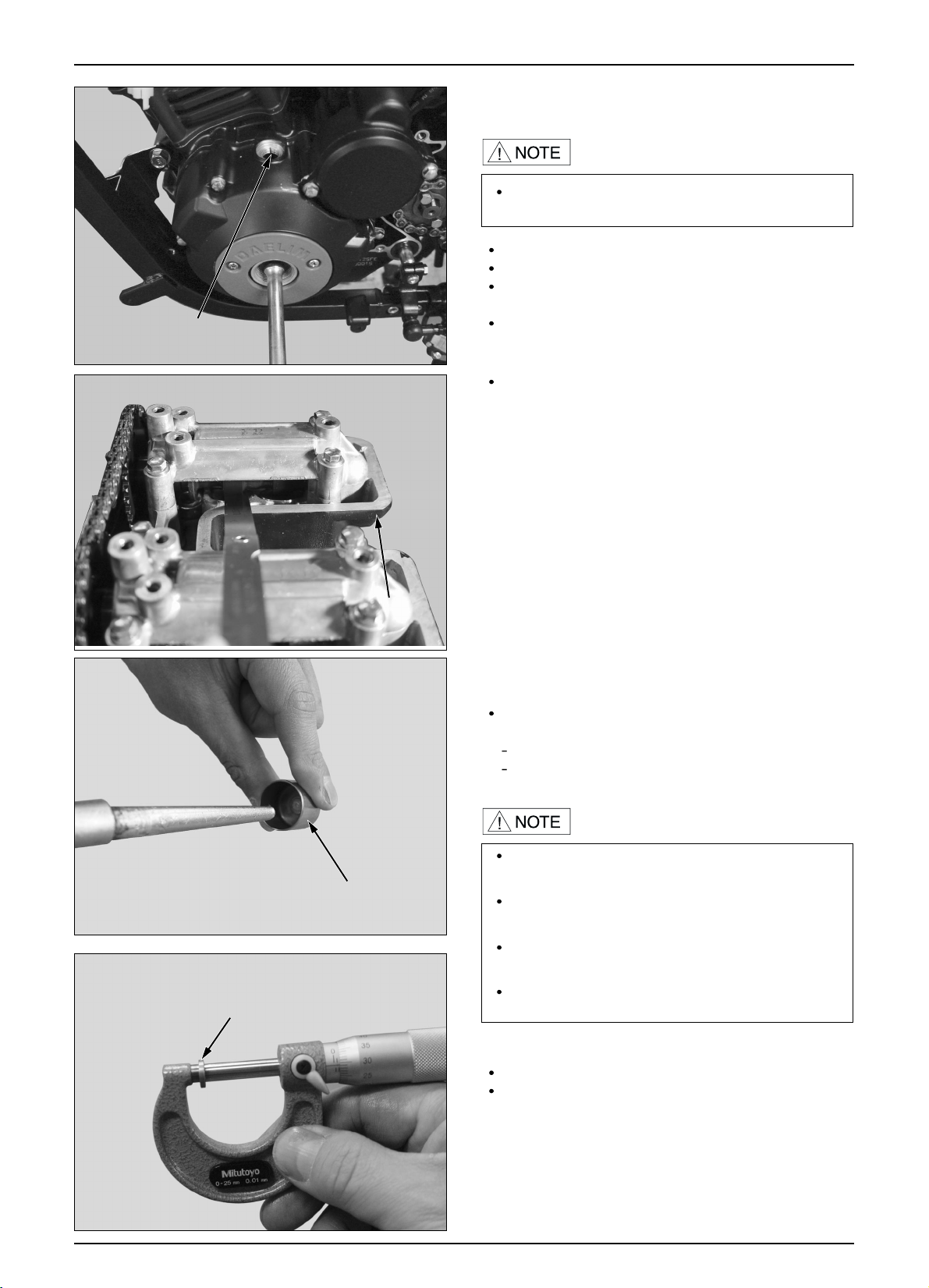
VALVE CLEARANCE
Remove the cylinder head cover.
Remove the A.C generator cap and crankcase hole cap.
Rotate the flywheel counterclockwise to align the "T"
mark with the index mark on the left crankcase cover.
Make sure the piston is at TDC(Top Dead Center) on
the compression stroke.
SHIM ADJUSTMENT
If the valve clearance is out of standard, adjust the shim
as below.
Remove the camshaft.
Remove the valve lifter and seam.
Remove the valve lifter and clean by compressed air.
Mop the oil from the attahed area of shim, and measure
and record the thinkness with a micrometer.
Inspect and adjust valve clearance while the engine
is cold. (below 35° C/95°F)
If the valve lifter is to be removed, use the special
tool.
Be careful not to drop the shim into the cylinder
when remove the shim with valve lifter.
If it is too difficult to remove the shim, use a tweezer
or magnet.
Valve lifter, and shim should be preserved on the
assembly position distinguishably.
“T” MARK
“T” MARK
“T” MARK
“T” MARK
“T” MARK
“T” MARK
“T” MARK
“T” MARK
“T” MARK
“T” MARK
“T” MARK
“T” MARK
“T” MARK
“T” MARK
“T” MARK
“T” MARK
“T” MARK
“T” MARK
Measure the valve clearance with a feeler gauge.
VALVE CLEARANCE : INTAKE : 0.15mm
EXHAUST : 0.20mm
SHIM
SHIM
SHIM
SHIM
SHIM
SHIM
SHIM
SHIM
SHIM
SHIM
SHIM
SHIM
SHIM
SHIM
SHIM
SHIM
SHIM
SHIM
SHIM
SHIM
SHIM
SHIM
VALVE RIFTER
VALVE RIFTER
VALVE RIFTER
VALVE RIFTER
VALVE RIFTER
VALVE RIFTER
VALVE RIFTER
VALVE RIFTER
VALVE RIFTER
VALVE RIFTER
VALVE RIFTER
VALVE RIFTER
VALVE RIFTER
VALVE RIFTER
VALVE RIFTER
VALVE RIFTER
VALVE RIFTER
VALVE RIFTER
VALVE RIFTER
VALVE RIFTER
VALVE RIFTER
VALVE RIFTER
Page 31

2-7
INSPECTIONS / ADJUSTMENTS
The type of shim is 33
The clearance of shim is 1,500mm to 2,300mm with
0.025mm clearance.
The maximum reading is usually reached within
4~7seconds
compression 13.0kg f/
Meaure the thickness of new shim and removed shim,
using a micrometer accurately.
If the demanded thickness of shim is over 2,300mm,
to check the valve seat and remove the carbon deposit
and modify the valve seat.
Demanded thickness of shim :A
Recorded clearance of the valve lifter : B
Specified clearance of the valve lifter : C
(In :0.15mm / Ex : 0.20mm)
Removed thickness of the shim : D
how to calculate : A = (B-C)+D
Example)
B : 0.06mm
D : 1.875mm
C :
0.15mm(IN)
A = (0.06-0.15)+1.875mm
New thickness of the shim : 1.775mm
Install the chosen shim into the valve spring retainer.
Apply the molybdenum to wet side of valve lifter and
install the lifter.
Install the cam shaft and rotate the crank shaft for many
timed and recheck the valve clearance after setting the
shim.
Apply the engine oil to O-ring of pulse generator cover
cap and install the cap.
TORQUE : 0.6kgf-m
CYLINDER COMPRESSION PRESSURE
Warm up the engine to normal operating temperature.
Stop the engine, disconnect the spark plug caps and
spark plug. install the compression gauge. open the
throttle completely and crank the engine with the
starter motor until the gauge reading stops rising.
Tool:compression gauge.
If compression is low, check the following
Incorrect valve clearance adjustment.
Valve leakage.
Leak the gasket from the cylinder head.
Worn piston/cylinder.
If compression is high, check the following
Carbon deposits on the piston head, cylinder head.
COMPRESSION PRESSURE GAUGE
COMPRESSION PRESSURE GAUGE
COMPRESSION PRESSURE GAUGE
COMPRESSION PRESSURE GAUGE
COMPRESSION PRESSURE GAUGE
COMPRESSION PRESSURE GAUGE
COMPRESSION PRESSURE GAUGE
COMPRESSION PRESSURE GAUGE
COMPRESSION PRESSURE GAUGE
COMPRESSION PRESSURE GAUGE
COMPRESSION PRESSURE GAUGE
COMPRESSION PRESSURE GAUGE
COMPRESSION PRESSURE GAUGE
COMPRESSION PRESSURE GAUGE
COMPRESSION PRESSURE GAUGE
COMPRESSION PRESSURE GAUGE
COMPRESSION PRESSURE GAUGE
COMPRESSION PRESSURE GAUGE
COMPRESSION PRESSURE GAUGE
COMPRESSION PRESSURE GAUGE
COMPRESSION PRESSURE GAUGE
COMPRESSION PRESSURE GAUGE
Page 32

2-8
DRIVE CHAIN
DRIVE CHAIN SLACK ADJUSTMENT
Turn off the ignition switch, support the motorcycle
on its main stand, and shift the transmission into
neutral.
Check slack in the lower chain with a hand midway
between the sprockets.
CHAIN SLACK : 10~20mm
Adjust the slack of drive chain if necessary.
Adjust it by loosening the axle nut, loosening both
lock nuts of adjust, and turning the adjusting nut.
Tighten the axle nut with the specified torque.
TORQUE : 8.8kgf m(88N m)
REMOVAL
In case that the drive chain becomes extremely
dirty, it should be cleaned before lubrication.
Remove the drive sprocket cover. Remove the
retainer clip.
Remove the master link, drive chain.
(chain color change : Black
Gold)
INSPECTIONS / ADJUSTMENTS
Because there is a danger which fingers get jammed
in the drive chain, never inspect or adjust it while
the engine is running.
Make sure that the chain adjuster scale are aligned
with the correspondidng scale graduations on both
sides of the swing arm.
ADJUSTING NUT
ADJUSTING NUT
ADJUSTING NUT
ADJUSTING NUT
ADJUSTING NUT
ADJUSTING NUT
ADJUSTING NUT
ADJUSTING NUT
ADJUSTING NUT
ADJUSTING NUT
ADJUSTING NUT
ADJUSTING NUT
ADJUSTING NUT
ADJUSTING NUT
ADJUSTING NUT
ADJUSTING NUT
LOCK NUT
LOCK NUT
LOCK NUT
LOCK NUT
LOCK NUT
LOCK NUT
LOCK NUT
LOCK NUT
LOCK NUT
LOCK NUT
LOCK NUT
LOCK NUT
LOCK NUT
LOCK NUT
LOCK NUT
LOCK NUT
LOCK NUT
LOCK NUT
AXLE NUT
AXLE NUT
AXLE NUT
AXLE NUT
AXLE NUT
AXLE NUT
AXLE NUT
AXLE NUT
AXLE NUT
AXLE NUT
AXLE NUT
AXLE NUT
AXLE NUT
AXLE NUT
AXLE NUT
AXLE NUT
10~20mm
10~20mm
10~20mm
10~20mm
10~20mm
10~20mm
10~20mm
10~20mm
10~20mm
10~20mm
10~20mm
10~20mm
10~20mm
10~20mm
10~20mm
10~20mm
RETAINER CLIP
RETAINER CLIP
RETAINER CLIP
RETAINER CLIP
RETAINER CLIP
RETAINER CLIP
RETAINER CLIP
RETAINER CLIP
RETAINER CLIP
RETAINER CLIP
RETAINER CLIP
RETAINER CLIP
RETAINER CLIP
RETAINER CLIP
130 LINKS
RETAINER CLIP
ROTATING DIRECTION
Check the drive chain for adherence and damaging.
Measure the length between the chain’s pins and
replace the chain if the prescribed limits are
exceeded.
Drive chain length (130 links).
Page 33

2-9
INSPECTIONS / ADJUSTMENTS
DRIVE CHAIN INSPECTION
Lubricate with #80-90 gear oil after removing the
contamination of chain with a cleaner, and drying
fully.
Because an extremely lubricated oil splash while
the chain moves round, clean it with a piece of
cloth.
After checking a wear and damage of the drive
chain, replace it if necessary.
After inspecting an excessive wear and damage of
the drive sprocket, replace it if necessary.
DRIVE CHAIN INSTALLATION
Install the drive chain.
Install the master link and retainer clip.
Check the attaching bolts and nuts on the drive and
driven sprockets.
If any are loose, tighten them to the specified torque.
TORQUE :
DRIVE SPROCKET BOLT : 1.2kgf m(12N m)
DRIVE SPROCKET NUT : 5.9kgf m(59N m)
Always replace the chain and sprocket as a set.
Because using the stretched chain and new sprocket
or similar case, the parts will damage quickly cause
by the pictch is not engage each other.
When installing the drive chain, it should be installed
in order that the choked part of the clip can direct to
a progressing derection of the chain.
WIPE AND DRY
GEAR OIL(#80-90)
DAMAGE
WEAR
NORMAL
RETAINER CLIP
MASTER LINK
OUTSIDE
RETAINER CLIP
DRIVE SPROCKET
DRIVE SPROCKET
DRIVE SPROCKET
DRIVE SPROCKET
DRIVE SPROCKET
DRIVE SPROCKET
DRIVE SPROCKET
DRIVE SPROCKET
DRIVE SPROCKET
DRIVE SPROCKET
DRIVE SPROCKET
DRIVE SPROCKET
DRIVE SPROCKET
DRIVE SPROCKET
DRIVE SPROCKET
DRIVE SPROCKET
Page 34

2-10
INSPECTIONS / ADJUSTMENTS
BRAKE FLUID
DRIVE CHAIN SLIDER
Inspect the drive chain slider for excessive wear or
damage.
If it is worn to the wear indicator, replace the drive
chain slider.
When the fluid level is low, check the brake pads
for wear. If the brake pads are not worn and the
fluid level is low, check entire system for leaks.
(
2-11)
FRONT BRAKE
Turn the handlebar so that the reservoir is level and
check the front brake fluid reservoir level.
If the level is near the lower level line, check the brake
pad wear.
REAR BRAKE
Place the motorcycle on a level surface, and support it
upright position.
Check the rear brake fluid reservoir level.
If the level is near the lower level line, check the brake
pad wear.
BRAKE PAD WEAR
FRONT BRAKE PADS
Check the brake pads for wear.
Replace the brake pads if either pad is worn to the
bottom of wear limit groove.
Refer to page 16-6 for brake pad replacement.
Do not mix a dust or different types of fluid when
filling the brake fluid.
Mind that the reservoir is level in checking and
filling it.
Avoid spilling the fluid on painted, plastic, or
rubber parts.
LOWER LEVEL LINE
LOWER LEVEL LINE
LOWER LEVEL LINE
LOWER LEVEL LINE
LOWER LEVEL LINE
LOWER LEVEL LINE
LOWER LEVEL LINE
LOWER LEVEL LINE
LOWER LEVEL LINE
LOWER LEVEL LINE
LOWER LEVEL LINE
LOWER LEVEL LINE
LOWER LEVEL LINE
LOWER LEVEL LINE
LOWER LEVEL LINE
LOWER LEVEL LINE
FR. BRAKE FLUID
FR. BRAKE FLUID
FR. BRAKE FLUID
FR. BRAKE FLUID
FR. BRAKE FLUID
FR. BRAKE FLUID
FR. BRAKE FLUID
FR. BRAKE FLUID
FR. BRAKE FLUID
FR. BRAKE FLUID
FR. BRAKE FLUID
FR. BRAKE FLUID
FR. BRAKE FLUID
FR. BRAKE FLUID
FR. BRAKE FLUID
FR. BRAKE FLUID
RR. BRAKE FLUID
RR. BRAKE FLUID
RR. BRAKE FLUID
RR. BRAKE FLUID
RR. BRAKE FLUID
RR. BRAKE FLUID
RR. BRAKE FLUID
RR. BRAKE FLUID
RR. BRAKE FLUID
RR. BRAKE FLUID
RR. BRAKE FLUID
RR. BRAKE FLUID
RR. BRAKE FLUID
RR. BRAKE FLUID
RR. BRAKE FLUID
. BRAKE FLUID
LOWER LEVEL LINE
LOWER LEVEL LINE
LOWER LEVEL LINE
LOWER LEVEL LINE
LOWER LEVEL LINE
LOWER LEVEL LINE
LOWER LEVEL LINE
LOWER LEVEL LINE
LOWER LEVEL LINE
LOWER LEVEL LINE
LOWER LEVEL LINE
LOWER LEVEL LINE
LOWER LEVEL LINE
LOWER LEVEL LINE
LOWER LEVEL LINE
LOWER LEVEL LINE
UPPER LEVEL LINE
UPPER LEVEL LINE
UPPER LEVEL LINE
UPPER LEVEL LINE
UPPER LEVEL LINE
UPPER LEVEL LINE
UPPER LEVEL LINE
UPPER LEVEL LINE
UPPER LEVEL LINE
UPPER LEVEL LINE
UPPER LEVEL LINE
UPPER LEVEL LINE
UPPER LEVEL LINE
UPPER LEVEL LINE
UPPER LEVEL LINE
UPPER LEVEL LINE
WEAR
INDICATOR
WEAR INDICATOR
UPPER
LOWER
Page 35

10~20mm
10~20mm
10~20mm
10~20mm
10~20mm
10~20mm
10~20mm
10~20mm
10~20mm
10~20mm
10~20mm
10~20mm
10~20mm
10~20mm
10~20mm
10~20mm
2-11
INSPECTIONS / ADJUSTMENTS
BRAKE SYSTEM
Check to see if there is a crack and damage in the
front and rear brake hose.
If leak, repluce it with new one.
REAR BRAKE PADS
Check the brake pads for wear.
Replace the brake pads if either pad is worn to the
bottom of wear limit groove.
Refer to page 16-7 for brake pad replacement.
FRONT BRAKE LEVER FREE PLAY
Check the free play after pulling the lever.
BRAKE LEVER FREE PLAY : 10~20mm
REAR BRAKE PEDAL FREE PLAY
Adjust the brake pedal free play at the end part of
pedal.
BRAKE PEDAL FREE PLAY : 10~20mm
BRAKE HOSE
BRAKE HOSE
BRAKE HOSE
BRAKE HOSE
BRAKE HOSE
BRAKE HOSE
BRAKE HOSE
BRAKE HOSE
BRAKE HOSE
BRAKE HOSE
BRAKE HOSE
BRAKE HOSE
BRAKE HOSE
BRAKE HOSE
BRAKE HOSE
BRAKE HOSE
10~20mm
10~20mm
10~20mm
10~20mm
10~20mm
10~20mm
10~20mm
10~20mm
10~20mm
10~20mm
10~20mm
10~20mm
10~20mm
10~20mm
10~20mm
10~20mm
WEAR INDICATOR
Page 36

2-12
INSPECTIONS / ADJUSTMENTS
BRAKE PEDAL HEIGHT ADJUSTMENT
Loosen the lock nut and turn the stopper bolt until
the correct pedal height is obtained.
After adjustment, tighten the lock nut securely.
After adjusting the brake pedal height, inspect the
operation of rear brake light switch and brake pedal,
and adjust them if necessary.
BRAKE STOP SWITCH
Adjust the brake stop switch by turning the adjust
nut, pressing the switch so that the brake light will
come on just before the brake pedal is depressed
and brake engagement begins.
HEADLIGHT AIM
Adjust the headlight beam vertically by turning the
headlight case adjustment bolts.
CLUTCH SYSTEM
Measure the clutch lever free play at the end of the
clutch lever.
FREE PLAY : 10~20mm
Adjust the headlight beam as specified by local
laws and regulations.
An improperly adjusted headlight may blind
oncoming drivers, or it may fail to light the road
for a safe distance.
BRAKE STOP SWITCH
BRAKE STOP SWITCH
BRAKE STOP SWITCH
BRAKE STOP SWITCH
BRAKE STOP SWITCH
BRAKE STOP SWITCH
BRAKE STOP SWITCH
BRAKE STOP SWITCH
BRAKE STOP SWITCH
BRAKE STOP SWITCH
BRAKE STOP SWITCH
BRAKE STOP SWITCH
BRAKE STOP SWITCH
BRAKE STOP SWITCH
BRAKE STOP SWITCH
BRAKE STOP SWITCH
STOPPER BOLT
STOPPER BOLT
STOPPER BOLT
STOPPER BOLT
STOPPER BOLT
STOPPER BOLT
STOPPER BOLT
STOPPER BOLT
STOPPER BOLT
STOPPER BOLT
STOPPER BOLT
STOPPER BOLT
STOPPER BOLT
STOPPER BOLT
STOPPER BOLT
STOPPER BOLT
The adjustment faulty of height may caused that the
brake runs in state of operation.
Page 37

2-13
INSPECTIONS / ADJUSTMENTS
Minor adjustments are made using the upper
adjuster at the clutch lever.
Loosen the lock nut and turn the adjuster.
Major adjustments are performed at the clutch arm.
Loosen the lock nut and turn the adjuster nut to
adjust free play.
Hold the adjuster nut securely while tightening the
lock nut.
If proper free play cannot be obtained, or the clutch
slips during test ride, disassemble and inspect the
clutch.
SIDE STAND
Erect the main stand.
Pull the lower end of the side stand, and see if it
moves freely.
If the side stand does not move smoothly, apply
grease to the pivot area.
If the side stand moves too freely, check the side
stand spring.
Check the axial movement of the side stand.
Check the side stand switch:
- Sit astride the motorcycle and raise the side stand.
- Start the engine with the transmission in neutral.
- Lower the side stand.
The engine should not accelerate as the throttle
grip is operated.
If there is a problem with the system, check the
side stand switch.
LOCK NUT
LOCK NUT
LOCK NUT
LOCK NUT
LOCK NUT
LOCK NUT
LOCK NUT
LOCK NUT
LOCK NUT
LOCK NUT
LOCK NUT
LOCK NUT
LOCK NUT
LOCK NUT
LOCK NUT
LOCK NUT
LOCK NUT
LOCK NUT
ADJUSTER
ADJUSTER
ADJUSTER
ADJUSTER
ADJUSTER
ADJUSTER
ADJUSTER
ADJUSTER
ADJUSTER
ADJUSTER
ADJUSTER
ADJUSTER
ADJUSTER
ADJUSTER
ADJUSTER
ADJUSTER
ADJUSTER
ADJUSTER
SIDE STAND SWITCH
Page 38

2-14
INSPECTIONS / ADJUSTMENTS
REAR SUSPENSION
Compress the near cushion up and down several
times to check the operating conditions.
Check the rear cushion for oil leakage, parts
damage or looseness
.
BOLTS, NUTS, FASTENERS
Check that all frame nuts and bolts are tightened to
their correct torque values. (
2-3)
Check that all safety clips, hose clamps and cable
stays are in place and properly secured.
Erect the motorcycle with the main stand.
Check a wear of the rear fork bush by moving the
rear wheel aside. If there is a free play, replace the
rear fork bush.
Tighten all nuts and bolts of the rear suspension.
FRONT SUSPENSION
Hold the brake lever, and compress the front
cushion up and down several times to check the
operating conditions.
Check the front fork for oil leakage, parts damage
or looseness.
SUSPENSION
Do not ride motorcycle with an unsatisfactory
suspension. Loose or worn suspension parts will
lead to deterioration in the vehicle's safety and
operation efficiency.
Page 39

2-15
INSPECTIONS / ADJUSTMENTS
Check the tread depth at the tire center.
If the tread depth has reached the service limit,
replace the tires.
SERVICE LIMIT : FRONT : 5.5mm
REAR : 7.0mm
Erect the motorcycle securely and raise the front
wheel off the ground.
Check that the handlebar moves freely from side to
side.
If the handlebar moves unevenly, binds or has
vertical movement, inspect the steering stem.
STEERING STEM
Check that the cables do not interfere with
handlebar rotation.
STANDARD PRESSURE
WHEEL/TIRE
Check the tire pressure when the tires have been
cooled off. Check the tread (the part making
contact with the road surface) and side for wear,
cracks or damage. Replace damaged tires.
FRONT WHEEL
2.00(200)
2.00(200)
REAR WHEEL
2.00(200)
2.25(225)
ITEM
DRIVER ONLY
DRIVER AND A PASSENGER
f/ (kpa)
Page 40

2-16
Start the engine. Bleed air from the coolant and
check the level of coolant.
Install the radiator cap.
Fill the coolant with the reserve tank up to the
upper level.
INSPECTIONS / ADJUSTMENTS
Erect the main stand prior to beginning work.
Check the coolant level and the reserve tank.
The level should be between the “UPPER” and
“LOWER” level lines.
Fill the coolant to the reserve tank up to the “F”
(upper level).
Remove the drain bolt and drain the coolant. (Tilt
the vehicle to the right in order to assure complete
and rapid draining.)
Remove the radiator cap.
Install the drain bolt.
Fill the radiator with new coolant.
COOLANT CAPACITY : 1,280 20cc
RADIATOR CAPACITY : 1,000 20cc
RESERVE TANK CAPACITY: 280 20cc
COOLANT LEVEL INSPECTION
COOLANT REPLACEMENT
Unless the coolant is refilled or replaced, the
engine temperature too high or low.
Fill to the “F”(UPPER LEVEL) line.
Page 41

3-1
3. LUBRICATION
SERVICE INFORMATION
GENERAL SAFETY
The exhaust gas contains poisonous substance. Do not keep engine idling in a closed or poorly ventilated place for a
long period of time.
Used engine oil may cause skin cancer if repeatedly left in contact with the skin for prolonged periods. It is desirable
not to handle used oil frequently; however, wash your hands thoroughly with soap and water immediately after
handling the used oil.
The oil pump can be serviced without removing the engine from the frame.
ENGINE OIL
TORQUE VALUES
TAPPET ADJUST HOLE CAP
1.5 f m (15N m)
OIL FILTER COVER BOLT
1.1
f m (11N m)
SERVICE INFORMATION 3-1
TROUBLESHOOTING
3-2
ENGINE OIL LEVEL INSPECTION
3-3
ENGINE OIL CHANGE
3-3
OIL FILTER ELEMENT CHANGE
3-4
OIL PUMP
3-4
LUBRICATION POINTS
3-7
OIL CAPACITY
RECOMMENDED
OIL
1.5 (After disassembly)
1.35
(After Oil filter change)
1.3
(After Oil change)
API service classification : SE, SF, SH grade
Viscosity : SAE10W-30
(Use appropriate type of oil with viscosity satisfying
the atmospheric temperature in your riding area
based on the table shown on the right side.)
-10 0 10 20 30 40
PUMP BODY CLEARANCE 0.15~0.20 0.25
ROTOR END CLEARANCE 0.15 0.20
ITEM STANDARD VALUE SERVICE LIMIT
OIL PUMP
Unit : mm
Page 42

3-2
LUBRICATION
TROUBLESHOOTING
Engine oil level too low
Oil consumption naturally.
External oil leaks.
Worn piston ring or incorrect piston ring installation.
Worn valve guide or seal.
Oil contamination
Oil or filter not changed regularly.
Faulty head gasket.
Worn piston rings.
Low or no oil pressure
Clogged oil orifice.
Incorrect oil being used.
Page 43

ENGINE OIL LEVEL INSPECTION
Erect the motorcycle by main stand.
Start the engine and let it be warm fully.
Stop the engine, remove the oil level gauge and wipe it
clean.
Check the oil level with the level gauge by inserting it
in engine screwing level gauge.
It is good if the oil surface is between the lower level
mark and upper that of the level gauge. If the oil level
is near the lower level mark on the dipstick or below
that, full to the upper level mark with the recommended
oil.
ENGINE OIL CHANGE
Remove the tappet adjust hole cap.
Take out the spring and screen or remove the spark
plug cap from the spark plug,
Start the starter motor for several times to drain any oil
which may be left in the engine.
Clean filter screen with a clean wash. Check if the oil
filter screen and O-ring of the screen cap are in good
condition.
Install the filter screen and spring.
Install and tighten the tappet adjust hole cap.
TORQUE : 1.5 kgf m(15N.m)
Fill the crankcase with recommened engine oil.
OIL CAPACITY: 1.5 (After disassembly)
1.35
(After oil filter change)
1.3
(After oil change)
RECOMMENDED ENGINE OIL :
Genuine oil
API classification : SE or SH
viscosity : 10W-30
Install the oil level gauge.
Start the engine and let it idle for a few minutes.
Stop the engine and recheck the oil level,if necessary,
supply the recommended oil.
Check to see if the oil is leak.
3-3
LUBRICATION
Make the engine warm and erect the motorcycle
with side stand in order to assure complete and rapid
draining.
OIL LEVEL GAUGE
OIL LEVEL GAUGE
OIL LEVEL GAUGE
OIL LEVEL GAUGE
OIL LEVEL GAUGE
OIL LEVEL GAUGE
OIL LEVEL GAUGE
OIL LEVEL GAUGE
OIL LEVEL GAUGE
OIL LEVEL GAUGE
OIL LEVEL GAUGE
OIL LEVEL GAUGE
OIL LEVEL GAUGE
OIL LEVEL GAUGE
OIL LEVEL GAUGE
OIL LEVEL GAUGE
OIL LEVEL GAUGE
OIL LEVEL GAUGE
TAPPET ADJUST HOLE CAP
TAPPET ADJUST HOLE CAP
TAPPET ADJUST HOLE CAP
TAPPET ADJUST HOLE CAP
TAPPET ADJUST HOLE CAP
TAPPET ADJUST HOLE CAP
TAPPET ADJUST HOLE CAP
TAPPET ADJUST HOLE CAP
TAPPET ADJUST HOLE CAP
TAPPET ADJUST HOLE CAP
TAPPET ADJUST HOLE CAP
TAPPET ADJUST HOLE CAP
TAPPET ADJUST HOLE CAP
TAPPET ADJUST HOLE CAP
TAPPET ADJUST HOLE CAP
TAPPET ADJUST HOLE CAP
TAPPET ADJUST HOLE CAP
TAPPET ADJUST HOLE CAP
TAPPET ADJUST HOLE CAP
TAPPET ADJUST HOLE CAP
TAPPET ADJUST HOLE CAP
TAPPET ADJUST HOLE CAP
TAPPET ADJUST HOLE CAP
TAPPET ADJUST HOLE CAP
TAPPET ADJUST HOLE CAP
TAPPET ADJUST HOLE CAP
TAPPET ADJUST HOLE CAP
TAPPET ADJUST HOLE CAP
TAPPET ADJUST HOLE CAP
TAPPET ADJUST HOLE CAP
TAPPET ADJUST HOLE CAP
TAPPET ADJUST HOLE CAP
OIL FILTER SCREEN
OIL FILTER SCREEN
OIL FILTER SCREEN
OIL FILTER SCREEN
OIL FILTER SCREEN
OIL FILTER SCREEN
OIL FILTER SCREEN
OIL FILTER SCREEN
OIL FILTER SCREEN
OIL FILTER SCREEN
OIL FILTER SCREEN
OIL FILTER SCREEN
OIL FILTER SCREEN
OIL FILTER SCREEN
OIL FILTER SCREEN
OIL FILTER SCREEN
OIL FILTER SCREEN
OIL FILTER SCREEN
Page 44

INNER ROTOR
INNER ROTOR
INNER ROTOR
INNER ROTOR
INNER ROTOR
INNER ROTOR
INNER ROTOR
INNER ROTOR
INNER ROTOR
INNER ROTOR
INNER ROTOR
INNER ROTOR
INNER ROTOR
INNER ROTOR
INNER ROTOR
INNER ROTOR
INNER ROTOR
INNER ROTOR
3-4
LUBRICATION
Always use a genuine oil filter element.
Be sure to replace the oil filter seal when removing
oil filter element.
Be careful not to lose the oil filter spring when
assembling the oil filter element.
OIL FILTER ELEMENT CHANGE
Drain the engine oil. ( 3-3)
Loosen the 3 flange bolts securing the oil filter cover
bolt, filter cover, the oil filter element and oil filter
spring.
Change the oil filter element with a new one.
Check if the oil filter seal is in good condition, if
necessary, replace it with new one.
Install the filter element, spring and oil filter cover and
tighten the bolts to the specified torque.
TORQUE : 1.1 kgf m (11 N m)
OIL PUMP
REMOVAL
Drain the engine oil. ( 3-3)
Remove the oil filter. ( 3-4)
DISASSEMBLY
Clean the oil pump body, inner and outer rotors with
fresh cleaning oil.
OIL FILTER COVER
OIL FILTER COVER
OIL FILTER COVER
OIL FILTER COVER
OIL FILTER COVER
OIL FILTER COVER
OIL FILTER COVER
OIL FILTER COVER
OIL FILTER COVER
OIL FILTER COVER
OIL FILTER COVER
OIL FILTER COVER
OIL FILTER COVER
OIL FILTER COVER
OIL FILTER COVER
OIL FILTER COVER
OIL FILTER COVER
OIL FILTER COVER
OIL FILTER ELEMENT
OIL FILTER ELEMENT
OIL FILTER ELEMENT
OIL FILTER ELEMENT
OIL FILTER ELEMENT
OIL FILTER ELEMENT
OIL FILTER ELEMENT
OIL FILTER ELEMENT
OIL FILTER ELEMENT
OIL FILTER ELEMENT
OIL FILTER ELEMENT
OIL FILTER ELEMENT
OIL FILTER ELEMENT
OIL FILTER ELEMENT
OIL FILTER ELEMENT
OIL FILTER ELEMENT
OIL FILTER ELEMENT
OIL FILTER ELEMENT
OUTER ROTOR
OUTER ROTOR
OUTER ROTOR
OUTER ROTOR
OUTER ROTOR
OUTER ROTOR
OUTER ROTOR
OUTER ROTOR
OUTER ROTOR
OUTER ROTOR
OUTER ROTOR
OUTER ROTOR
OUTER ROTOR
OUTER ROTOR
OUTER ROTOR
OUTER ROTOR
OUTER ROTOR
OUTER ROTOR
Page 45

3-5
LUBRICATION
INSPECTION
Install the inner and outer rotors into the oil pump
body.
Measure the pump body clearance.
SERVICE LIMIT : 0.25mm
ASSEMBLY
Clean all parts with fresh cleaning oil.
Install the lnner and outer rotor to the pump body.
INSTALLATION
Install the oil filter cover to the RH.crank case.
Fill the recommended oil into the crankcas.
Measure the rotor end clearance.
SERVICE LIMIT : 0.20mm
After installing, check the oil pump to operate
smothly
Page 46

LUBRICATION POINTS
3-6
LUBRICATION
Use general grease
Page 47

MEMO
Page 48

4-0
FUEL SYSTEM
Page 49

4-1
SERVICE INFORMATION
GENERAL SAFETY
Gasoline is extremely flammable. Avoid fire in the work place, also paying particular attention to sparks. Furthermore,
the evaporated (gasified) gasoline is highly explosive. Work in a well-ventilated areas.
Exhaust gas contains poisonous substance. Do not keep engine running for a long period of time in a closed, or poorly
ventilated area.
STANDARD OF MAINTENANCE
Fuel tank capacity : 14.85
Reserve fuel capacity: 4.0
Fuel pump specification : KGF38
Flow quantity : Mimnim 20
Flow pressure : 380kpa
Injector specification
Injector angle : 15
Operation pressure : 380kpa
TORQUE VALUE
Air cleaner case cover screw 0.43kgf m (4.3N m)
TOOL
Float level gauge
4. FUEL SYSTEM
SERVICE INFORMATION 4-1
TROUBLESHOOTING 4-2
FUEL TANK 4-3
AIR CLEANER CASE 4-4
TROUBLESHOOTING
Engine cranks but won’t start
No fule in tank
No fule to carburetor
Cylinder flooded with fuel
Clogged air cleaner
No spark at plug
Page 50

FUEL FILLER CAP
FUEL TANK COVER
FUEL TANK SEALING RUBBER
FUEL PUMP
FUEL TANK
FUEL CAP NECK
FULE TANK
REMOVAL
INSTALLATION
Install the fuel tank in the reverse order of removal.
After installation, check if there is a gasoline leak.
Remove the seat.
Remove the fuel filler cap by looseing the 4 socket
bolts.
Remove the fuel tank cover by looseing the 2
special screws and washer bolt.
Remove the LH. side cover.
Disconnect the fuel unit wire coupler.
(Yellow/White and Green terminal)
Disconnect the fuel tubes from the fuel tank.
Remove the fuel tank upside down.
If fuel is in short supply at the fuel cock, remove the
gasoline in the tank, and clean the strainer screen by
loosening the fuel cock.
Do not smoke or allow flames or sparks in the
work area because gasoline is extremely
flammable. Immediately wipe off a leaked
gasoline.
SOCKET BOLTS
SOCKET BOLTS
SOCKET BOLTS
SOCKET BOLTS
SOCKET BOLTS
SOCKET BOLTS
SOCKET BOLTS
SOCKET BOLTS
SOCKET BOLTS
SOCKET BOLTS
SOCKET BOLTS
SOCKET BOLTS
SOCKET BOLTS
SOCKET BOLTS
SOCKET BOLTS
SOCKET BOLTS
FUEL TANK COVER
FUEL TANK COVER
FUEL TANK COVER
FUEL TANK COVER
FUEL TANK COVER
FUEL TANK COVER
FUEL TANK COVER
FUEL TANK COVER
FUEL TANK COVER
FUEL TANK COVER
FUEL TANK COVER
FUEL TANK COVER
FUEL TANK COVER
FUEL TANK COVER
FUEL TANK COVER
FUEL TANK COVER
FUEL
FUEL
FUEL
FUEL
FUEL
FUEL
FUEL
FUEL
FUEL
FUEL
FUEL
FUEL
FUEL
FUEL
FUEL
FUEL
FUEL
FUEL
FUEL
FUEL
FUEL
FUEL
FUEL
FUEL
FUEL
FUEL
FUEL
FUEL
FUEL
FUEL
FUEL
FUEL
FUEL
FUEL
4-2
FUEL SYSTEM
Be careful not to damage the fuel tank.
Page 51

4-3
FUEL SYSTEM
Insert the hook area of battery box into the front
hole of rear fender accurately when assemble the
air cleaner case.
AIR CLEANER CASE
AIR CLEANER INNER PIPE
AIR CLEANER ELEMENT
AIR CLEANER CASE COVER
AIR CLEANER CASE
REMOVAL
Remove the main seat.
Remove the fuel tank.
Remove the RH. LH. side covers.
Remove the battery.
Remove the battery box by loosening the washer
bolt.
Remove the air cleaner connecting tube band.
Remove the air cleaner case mounting bolts, then
remove the air cleaner case.
INSTALLATION
Install in the reverse order of removal.
AIR CLEANER
AIR CLEANER
AIR CLEANER
AIR CLEANER
AIR CLEANER
AIR CLEANER
AIR CLEANER
AIR CLEANER
AIR CLEANER
AIR CLEANER
AIR CLEANER
AIR CLEANER
AIR CLEANER
AIR CLEANER
AIR CLEANER
AIR CLEANER
AIR CLEANER CONNECTING
TUBE BAND
AIR CLEANER CONNECTING
TUBE BAND
AIR CLEANER CONNECTING
TUBE BAND
AIR CLEANER CONNECTING
TUBE BAND
AIR CLEANER CONNECTING
TUBE BAND
AIR CLEANER CONNECTING
TUBE BAND
AIR CLEANER CONNECTING
TUBE BAND
AIR CLEANER CONNECTING
TUBE BAND
AIR CLEANER CONNECTING
TUBE BAND
AIR CLEANER CONNECTING
TUBE BAND
AIR CLEANER CONNECTING
TUBE BAND
AIR CLEANER CONNECTING
TUBE BAND
AIR CLEANER CONNECTING
TUBE BAND
AIR CLEANER CONNECTING
TUBE BAND
AIR CLEANER CONNECTING
TUBE BAND
AIR CLEANER CONNECTING
TUBE BAND
WASHER BOLT
WASHER BOLT
WASHER BOLT
WASHER BOLT
WASHER BOLT
WASHER BOLT
WASHER BOLT
WASHER BOLT
WASHER BOLT
WASHER BOLT
WASHER BOLT
WASHER BOLT
WASHER BOLT
WASHER BOLT
WASHER BOLT
WASHER BOLT
Page 52

MEMO
Page 53

EMS(Engine Management System)
5-1
5. EMS(Engine Management System)
1. CAUTION WHEN REPAIRING THE EMS PARTS
5-2
2. THE COMPONENT PARTS OF THE EMS 5-3
3.TERMINAL ARRANGEMENT OF THE ECU 5-4
4. WIRING DIAGRAM OF THE ECU 5-4
5. SELF-DIAGNOSTIC FUNCTION BY MIL(Malfunction Indicator Lamp) 5-5
6. INJECTOR 5-11
7. MAPAT 5-14
8. TPS 5-18
9. ETS 5-21
10. ISA 5-24
11. O2(Oxygen) SENSOR 5-27
12. CHECKING OF ESS CIRCUIT
5-30
13. CHECKING OF MIL CIRCUIT
5-32
14. ECU (Electronic control unit)
5-33
15. CRANK POSITION SENSOR
5-34
16. FUEL PUMP 5-35
17. THROTTLE BODY
5-38
18. HOW TO USE SCAN
5-42
- SELF DIAGNOSTIC FUNCTION 5-5
- FAIL SAFE FUNCTION
5-6
- HOW TO CHECK
THE FAULT CODE
5-7
- HOW TO SHOW THE FAULT CODE
5-7
- HOW TO READ THE FAULT CODE
5-8
- FAULT CODE TABLE
5-9
- HOW TO REMOVE THE FAULT CODE
5-10
- EMS TROUBLE SHOOTING
5-10
-
WHEN THE ECU IS INITIALIZED
5-42
-WHEN THE ISA PWM ADJUSTING 5-44
-
WHEN THE IGNITION TIMING IS CHECK 5-45
-WHEN THE ENGINE RPM IS CHECK 5-46
Page 54

EMS(Engine Management System)
5-2
1.CAUTION WHEN REPAIRING THE EMS PARTS.
If the fuse is short-circuited, find out the cause and repair, replace with the fuse having the specified capacity.
Do not use the electlic wires or others instead of the fuse.
Do not drop or throw the EMS parts, because these parts may be damaged by the impact of the drop.
Do not touch the ECU terminal, because it may be damaged by the static.
The ignition key off before assembly and disassembly of the ECU coupler.
otherwise, it might be damage to ECU.
Do not connect adversely the polarity of battery, otherwise, it might be broken the EMS parts
While engine operating, do not disassemble the battery terminal.
otherwise, it might cause damaged the EMS parts.
Use the specified voltmeter and resistance meter.
Page 55

EMS(Engine Management System)
5-3
2.THE COMPONENT PARTS OF THE EMS
EMS CONSISTS OF INTAKE AND FULE, IGNITION AND CONTROL SYSTEM.
1) INTAKE SYSTEM
As a system which controls and measures air to be necessary for combustion in engine, the intake system
is composed of pressure sensor of intake parts, intake on sensor, throttle position sensor, throttle body, air
cleaner and ISA(Idle Speed Actuator), etc.
In idling, because throttle value is almost closed, the idle status of engine shall be controlled by means
that idle speed control system is installed in order to control small of quantity of air being necessary for
combustion.
2) FUEL SYSTEM
As a system to supply required fuel for consumption in engine combustion chamber from fuel tank to
injector, this Fuel system is composed of fuel tank, fuel pump, fuel filter, fuel pressure regulator, division
pipe and injector.
The fuel in tank, being high pressed by fuel pump, moves to the division pipe through fuel filter.
Next the fuel is supplied to injector being highly maintained as regulated pressure about the pressure of
intake system.
Injector sprays fuel into the intake system by injection signals of ECU.
3) IGNITION SYSTEM
The ignition system is composed of spark plug which makes ignition spark, a spark timing control part to
control proper spark time in cylinder, high-voltage system, and so forth.
4) CONTROL SYSTEM
Various sensors to move electric signals converted by checking the current engine status
Input interface which works various processes like regulating voltage levels, removal of noise, A/D
conversion, amplifying of inputted signals from above sensors.
Micro-computer which decides output value through various calculating, arithmetic and logic
processing.
Output interface to amplify the above output signals.
Actuator being mechanically worked by receiving the amplified output signals.
(Intake pressure sensor+Intake
temperature)
Page 56

EMS(Engine Management System)
5-4
3. TERMINAL ARRANGEMENT OF THE ECU
Remarks
ECU PIN NO. 5,6,7,8,11,14,15,16,36,38 were not connected.
Terminal arrangement is based on the ECU.
4. WIRING DIAGRAM OF THE ECU
Page 57

5.
SELF-DIAGNOSTIC FUNCTION BY MIL (Malfunction Indicator Lamp)
SELF-DIAGNOSTIC FUNCTION
The EMS is equipped with self-diagnostic function in order to ensure that the engine control system is operation
normally. If this function detects a malfunction in the system, it immediately operates and illuminates the MIL
(malfunction indicator lamp). It gives the rider that malfunction has occurred in the system.
However, the ECU takes fail-safe function, it enables to drive only temporary when that happen.
Normally, the MIL illuminates for 3 seconds, when the main key is turned on.
Remarks 1
If the EMS has some problem and the MIL on and off, engine starting and driving are temporary by the EMS’s
fail safe function. But the EMS is not normal condition, so check the vehicle and repair soonest.
Remarks 2
It might not be able to starting and driving when following problems happen.
- Crankposition sensor
- Injector
- Fuel pump
EMS(Engine Management System)
5-5
when the ignition key ON.
The MIL on and blink(when this function detects a malfunction in the system)
MIL
OFF
ON
Starting and driving are temporary
Unable to engine start
Able to engine start
MIL
ON
Blink
MIL on continuously, when the engine operating
MIL blinks, when the main key is turn on (engine is stop)
MIL(Malfuction Indicator Lamp)
Page 58

EMS(Engine Management System)
5-6
FAIL-SAFE FUNCTION
If the ECU checks something wrong , the vehicle can be driven by its fail safe function.
However, if there are something wrong in fuel pump, injector, crank position sensor, the engine operation
can be impossible.
If there is something wrong in the EMS, it has fail safe function in order for engine to
work and to cover a minimum driving of vehicle.
: MIL on/off
INTAKE
MIL
INTAKE
: MIL on
on
INTAKE
INTAKE
The value of intake pressure is fixed as the
pressure just before when the intake pressure
sensor is out of order.
The value of intake temperature is fixed as a
temperature just before when the intake
pressure sensor is out of order.
!
CAUTION
If the MIL on and blink, starting and driving are temporary by fail safe
function, but, because the conditions of engine operation are not perfect, this can be used in an urgent case.
In this case, safe repairing of vehicle shall be required.
Page 59

EMS(Engine Management System)
5-7
HOW TO CHECK THE FAULT CODE
There are two methods of checking the Fault codes.
1) Use the MIL in the Speedometer.
2) The diagnostic Tool.
First) Use the MIL in the Speedometer(refer to how to read the fault codes and Fault codes table and diagnostic
methods for each part)
Second) The diagnostic tool (refer to scan user’s manual.)
Turn off the ignition key
Disassemble the rh.side cover
The coupler to check the malfunction of vehicle is connected to the coupler of diagnostic tool.
(The coupler to check the malfunction of vehicle is placed in the rh.side cover)
Turn on the ignition key
Press the power button of diagnostic tool
Checks according to diagnostic procedure of diagnostic tool.
The wireharness to check the ECU
This wireharness is connected with the ECU and main wireharness
It has two couplers to check the terminals.
First coupler) ECU no.1~20
Second coupler) ECU no.21~40
Arrangement of ECU PIN
First coupler) ECU no.1,2,3,4,5,9,10,12,17,18,19,20 were connected
Second coupler) ECU no.36,38 were not connected
Wire color to check the malfunction diagnosis
-P/W : PINK/WHITE
-P/Y : PINK/YELLOW
-B : BLACK
-G : GREEN
Coupler to check the malfunction diagnosis
The diagnostic Tool.
The wireharness to check the ECU
Page 60

EMS(Engine Management System)
5-8
HOW TO SHOW THE FAULT CODE
There are two methods to show the Fault codes.
First, the methods to show in engine operation
In engine operation, when there is something wrong in each part of EMS, the MIL keeps light on without the
light on/off function of MIL in order for driver to acknowledge defect. This time, so for checking the fault code,
stop the vehicle and engine, and in the ignition key on, by checking the number of lighting, the fault code can be
verified.(refer to the fault code table)
Second,the ways of indication only turn on the ignition key.
When only ignition key is on and if the defect of each part brings out, the MIL keeps showing
the Fault code of defect part repeatedly in order to give defect information to driver.
If the MIL on when engine is working, engine is able to be operated by fail safe. However, in the event that
Injector, Fuel pump, Ignition coil has something wrong, vehicle may not been driven and engine not started
HOW TO READ THE FAULT CODE
The fault codes are showed as 2 digits on the MIL of EMS.
Only one defect code is showed up to prior sequence of defects. This time, that fault code is repeatedly showed.
E.g. ) The Fault code of ISA
If many problems will happened in the EMS parts at the same time only one fault code is displayed by the
priority, however, the ECU is remembers all the fault codes.
After revise the code, remove the memorized fault code by the method of warm up.(5-10)
(Refer to remove the fault codes)
When the vehicle is checked using the diagnosis tool.
- If the vehicle is check using the malfunction diagnosis tool, all fault code check is possible.
1 flashing cycle : 0.5 sec
1.5 sec 3 sec
ON
OFF
!
CAUTION
Page 61

EMS(Engine Management System)
5-9
FAULT CODES TABLE
No failure
Injection valve failure(IV)
Idle speed actuator failure (ISA)
Electrical fuel pump failure (EFP)
Intake Manifold absolute pressure signal
failure (IMP)
Throttle position signal failure (TPS)
O2 sensor heater output failure (LSH)
Lambda signal failure (VLS)
Engine temperature signal failure (TENG)
Breathing air temperature signal failure
(TBA)
Engine speed signal output failure (ESS)
Malfunction indicate lamp failure (MIL)
Page 62

EMS(Engine Management System)
5-10
HOW TO REMOVE THE FAULT CODE
Remove the fault codes in two ways;
First) Full warm up
1. Starting the engine.
- The MIL blinks continuously because the ECU memorized the fault code yet.
2. Full warm up the engine (keep idling five minutes)
3. Turn off the ignition key after full warm up the engine
4. Turn on the ignition key again, and check whether the fault code is disappeared or not.
After full warm up, it is possible to check the fault code is removed with the ignition key on/off.
If many problems happened in the EMS parts at the same time, only one defect code will is displayed
by the priority order.
Even thought repair a fault and remove the memorized fault code, another fault code blinks.
at this time, revise the fault and remove the memorized fault code by the warm up.
Second) Malfunction diagnosis tool
(refer to the scan user’s manual)
EMS TROUBLE SHOOTING
Inspection before diagnosis
Inspection the following before malfunction diagnosis.
Quantity of engine oil and leakage
Quantity of fuel and leakage
Blocked of air cleaner
Condition of battery
Free play of throttle cable
Cutting of fuse
Leakage of emission gas
Connection of each coupler
Page 63

EMS(Engine Management System)
5-11
Remove
Injector coupler
Injector cap bolt
Injector
6.INJECTOR
Be sure to check the engine is cooling because
a little gasoline remains. it could be still hot
and it could be cause fire.
!
CAUTION
The key is off before disassembly.
!
CAUTION
INJECTOR CAP
INJECTOR CAP
INJECTOR CAP
INJECTOR CAP
INJECTOR CAP
INJECTOR CAP
INJECTOR CAP
INJECTOR CAP
INJECTOR CAP
INJECTOR CAP
INJECTOR CAP
INJECTOR CAP
INJECTOR CAP
INJECTOR CAP
INJECTOR
INJECTOR
INJECTOR
INJECTOR
INJECTOR
INJECTOR
INJECTOR
INJECTOR
INJECTOR
INJECTOR
INJECTOR
INJECTOR
INJECTOR
INJECTOR
INJECTOR CONNECTOR
INJECTOR CONNECTOR
INJECTOR CONNECTOR
INJECTOR CONNECTOR
INJECTOR CONNECTOR
INJECTOR CONNECTOR
INJECTOR CONNECTOR
INJECTOR CONNECTOR
INJECTOR CONNECTOR
INJECTOR CONNECTOR
INJECTOR CONNECTOR
INJECTOR CONNECTOR
INJECTOR CONNECTOR
INJECTOR CONNECTOR
PRESS THE INJECTOR CAP
PRESS THE INJECTOR CAP
PRESS THE INJECTOR CAP
PRESS THE INJECTOR CAP
PRESS THE INJECTOR CAP
PRESS THE INJECTOR CAP
PRESS THE INJECTOR CAP
PRESS THE INJECTOR CAP
PRESS THE INJECTOR CAP
PRESS THE INJECTOR CAP
PRESS THE INJECTOR CAP
PRESS THE INJECTOR CAP
PRESS THE INJECTOR CAP
PRESS THE INJECTOR CAP
PULL THE INJECTOR CAP
PULL THE INJECTOR CAP
PULL THE INJECTOR CAP
PULL THE INJECTOR CAP
PULL THE INJECTOR CAP
PULL THE INJECTOR CAP
PULL THE INJECTOR CAP
PULL THE INJECTOR CAP
PULL THE INJECTOR CAP
PULL THE INJECTOR CAP
PULL THE INJECTOR CAP
PULL THE INJECTOR CAP
PULL THE INJECTOR CAP
PULL THE INJECTOR CAP
Page 64

EMS(Engine Management System)
5-12
CHECKING METHODS BY FAULT CODES
Checking of the Injector circuit
The fault code is displayed by MIL
Checking Circuit
Coupler terminal is based on wire harness.
ECU
40 : INJECTOR control
39 : FUEL PUMP control
INJECTOR FUEL PUMP RELAY
Page 65

EMS(Engine Management System)
5-13
CHECKING PROCEDURE
1) Turn off the ignition key.
2) Check to see if the injector coupler has come loose or the wire is peeling off.
If there is no problem, measured the resistance of injector.
3)Disassemble the injector coupler and measure the resistance between injector terminals.
The resistance of injector : 14.5±0.7[ ], 20
Remarks : measuring unit for resistance : resistance ‘ R ‘ [ ]
4)If there is no problem, check the continuity between each terminal and ground.
The resistance between each terminal and ground : ∞[ ]
If resistance value is not normal, replace injector with the new one.
5)If the resistance is normal, turns on the ignition key
- If the fuel pump operated for 3 seconds, the power supply relay of injector is normal.
6) Measure between the voltage of coupler.
Measuring terminal : BLACK/RED electric wire ~ ground
Measuring voltage : battery voltage – 1.0[V]over
Remarks : Measuring unit of voltage : voltage [V] 7) If the measured voltage is normal,
Check the ‘Blue/Yellow’ electric wire to see if they have been broken or have short-circuited
or if the wire-harness coupler and the ECU coupler are a bad contact (ECU terminal No. 40)
If there is no problem in the electric wires, ECU is broken
Replace the ECU with new one, it rechecks
8) If the measured voltage is not normal,
Check the Black/Red electric wire to see if they have been broken or have short-circuited.
Check the fuel pump relay.
9) After fault repaired, to erase the memorized fault code in the ECU is refer to how to remove the fault code(5-10).
Page 66

EMS(Engine Management System)
5-14
7. MAPAT(Manifold Air pressure
sensor, Temperature sensor)
Remove
MAPAT coupler.
(Push by hand and pull to the front-side)
Loosen the MAPAT sensor screw 2EA.
MAPAT sensor.
Be sure to check the coupler is toward upside.
!
CAUTION
It is Located on the left side of the throttle body.
MAPAT CONNECTOR
MAPAT CONNECTOR
MAPAT CONNECTOR
MAPAT CONNECTOR
MAPAT CONNECTOR
MAPAT CONNECTOR
MAPAT CONNECTOR
MAPAT CONNECTOR
MAPAT CONNECTOR
MAPAT CONNECTOR
MAPAT CONNECTOR
MAPAT CONNECTOR
MAPAT CONNECTOR
MAPAT CONNECTOR
MAPAT
MAPAT
MAPAT
MAPAT
MAPAT
MAPAT
MAPAT
MAPAT
MAPAT
MAPAT
MAPAT
MAPAT
MAPAT
MAPAT
TPS
TPS
TPS
TPS
TPS
TPS
TPS
TPS
TPS
TPS
TPS
TPS
TPS
TPS
The key is off before disassembly.
!
CAUTION
Page 67

EMS(Engine Management System)
5-15
Check the MAPAT Circuit(Intake Pressure Sensor (IMP)+Intake Temperature Sensor(TBA))’s circuit
Fault code number is displayed by MIL
The Fault code of intake pressure sensor The Fault code of intake temperature sensor
Checking circuit
Coupler terminal is based on the side of wire-harness
CHECKING PROCEDURE
1) Turn off the ignition key .
2) Check to see if the MAPAT coupler has come loose or the wire is peeling off.
If there is normal, measured the input voltage of MAPAT’s coupler.
3) Disassemble the coupler of MAPAT and turn on the ignition key
4) Measure the input voltage of MAPAT (intake pressure sensor + intake temperature sensor)’s coupler.
Input voltage : 4.5 ~ 5.5[V]
Measuring terminal : MAPAT 3 terminal ~ MAPAT 1 terminal
Remarks : Measuring unit of voltage : voltage [V]
If voltage value is not normal,
Check to see if the ECU coupler is loose or if there is a bad contact.
Check the ‘P’ electric wire, ‘P/G’ electric wire, ‘P/L’ to see if they have been broken short-circuited
Remark : refer to (5-16) if the intake pressure sensor is broken
refer to (5-16) if the intake temperature sensor is broken
5)After fault repaired, To erase the memorized fault code in the ECU is refer to how to remove the fault code(5-10).
3 : Intake pressure sensor ground
26 : 5V voltage
27 : IMP
28 : TBA
MAPAT
3 : Inhalation pressure
sensor GROUND
ECU
26 : 5V voltage
27 : IMP 28 : TBA
Page 68

EMS(Engine Management System)
5-16
CHECKING OF THE INTAKE PRESSURE SENSOR
1) If voltage value is normal, turn off the ignition key.
Connect the MAPAT(intake pressure sensor + intake temperature sensor) coupler
2) The wire-harness to check the ECU is connected with the ECU with a wire-harness coupler.
Refer to how to assemble or disassemble the ECU ( 5-32 )
3) Turn on the ignition key. Start engine and operate idle.
4) Measure the voltage of intake pressure sensor for ECU check.
Measuring the voltage of intake pressure sensor.
Measuring terminal : ECU No. 27(P/L:PINK/BLUE) ~ ECU No.3(P/G : PINK/GREEN)
Measuring voltage : 0.1[V] ~ 4.8[V]
Remarks : Measuring unit of voltage : Voltage [V]
The voltage of air pressure;
20[kPa]: 0.719 ~ 0.859[V]
107[kPa]: 4.154 ~ 4.294[V]
5) If the measured voltage is not normal,
Check the ‘P’ electric wire, ‘P/G’ electric wire, ‘P /L’ electric wire to see if they have been broken
or have short- circuited.
Replace the MAPAT sensor with the new one and it rechecks.
If measuring voltage is normal,
Check the ‘P’ electric wire, ‘P/G’ electric wire, ‘P/L’ electric wire to see if they have been broken or have
short- circuited if there is a bad contact.
badness of terminal No. 3, No. 26, No.27 of ECU coupler.
If the electric wire is no problem, ECU is broken.
Replace the ECU with the new one, it rechecks.
6) After repaired, refer to the fault code removal method to erase the memorized fault code in the ECU.
Checking of the intake temperature sensor
1) If voltage value is normal, turn off ignition key.
2) Disassemble the MAPAT coupler and measure the resistance of intake temperature sensor.
Resistance of intake pressure sensor : 2000±100[Ω], 25±1
Measuring terminal : ECU No. 28(P/B :PINK/BLUE) ~ ECU No. 3(P/G : PINK/GROUND)
Remarks : Measuring value for resistance : Resistance[ ]
The Voltage of air pressure;
24 ~ 26[ ] : 1800~2200[ ]
99 ~ 101[ ] : 161~206[ ]
3) If measuring resistance is not normal,
Replace the MAPAT sensor with new one and it rechecks.
If the measured voltage is normal,
Check the ‘P’ electric wire, ‘P/G’ electric wire, ‘P/L’ electric wire to see if they have been broken or have
short- circuited if there is a bad contact of terminal No. 3, No. 26, No. 28 of ECU coupler.
If the electric wire is no problem, ECU is broken.
Replace the ECU with the new one, it rechecks.
Page 69

EMS(Engine Management System)
5-17
CHECKING OF INTAKE TEMPERATURE SENSOR
1) If voltage value is normal, turn off ignition key.
2) Disassemble the MAPAT coupler and measure the resistance of intake temperature sensor.
Resistance of intake pressure sensor : 2000±100[Ω], 25±1
Measuring terminal : ECU No. 28(P/B :PINK/BLUE) ~ ECU No. 3(P/G : PINK/GROUND)
Remarks : Measuring value for resistance : Resistance[ ]
The Voltage of air pressure;
24 ~ 26[ ] : 1800~2200[ ]
99 ~ 101[ ] : 161~206[ ]
3) If measuring resistance is not normal,
Replace the MAPAT sensor with new one and it rechecks.
If the measured voltage is normal,
Check the ‘P’ electric wire, ‘P/G’ electric wire, ‘P/L’ electric wire to see if they have been broken or have
short- circuited if there is a bad contact of terminal No. 3, No. 26, No. 28 of ECU coupler.
If the electric wire is no problem, ECU is broken.
Replace the ECU with the new one, it rechecks. 4) Turn on the ignition key. Start the engine and idling.
5) Measure the voltage of intake pressure sensor for ECU check.
Measuring the voltage of intake pressure sensor
- Measuring terminal: ECU No.28(TBA)
~ ECU No.3(IMP ground)
- Measuring voltage: 0.1[V] ~ 4.9[V]
Remarks : Measuring unit of voltage : Voltage [V]
6) If the measured voltage is not normal,
Check the ‘P’ electric wire, ‘P/G’ electric wire, ‘P /L’ electric wire to see if they have been broken
or have short- circuited.
Replace the MAPAT sensor with new one and it rechecks.
If the measured voltage is normal,
Check the ‘P’ electric wire, ‘P/G’ electric wire, ‘P/L’ electric wire to see if they have been broken or have
short- circuited if there is a bad contact of terminal No. 3, No. 26, No.28 of ECU coupler.
If the electric wire is no problem, ECU is broken.
Replace ECU with the new one, it rechecks.
7) After fault repaired, To erase the memorized fault code in the ECU is refer to how to remove the fault code(5-10).
Page 70

EMS(Engine Management System)
5-18
8.TPS(THROTTLE POSITION SENSOR)
Remove
LH.side cowl
TPS coupler
Remove
TPS screw 2EA
Replace the TPS
It is Located on the right side of throttle body
The key is off before disassembly.
!
CAUTION
ETS
ETS
ETS
ETS
ETS
ETS
ETS
ETS
ETS
ETS
ETS
ETS
ETS
ETS
ETS
ETS
ETS
ETS
ETS
ETS
ETS
ETS
Page 71

EMS(Engine Management System)
5-19
CHECKING THE TPS(Throttle Position Sensor) CIRCUIT DIAGRAM
Fault code number is displayed by MIL
Checking circuit
The coupler terminal is based on the side of wire-harness
Checking Procedure
1) Turn off ignition key .
2) Check the TPS(Throttle Position Sensor) coupler is loose, or bad.
If there is no defect, measure the input voltage of TPS.
3) Disassemble the TPS coupler
4) Turn on the ignition key.
Input voltage : 4.5 ~ 5.5[V]
Measuring terminal : ECU NO.18(Gr/B : GRAY/BLACK) ~ ECU NO.4 (W/R : WHITE/RED)
Measure the terminal voltage of TPS’s coupler.
Measuring voltage : 4.5[V] ~ 5.5[V]
Remarks : Measuring unit of voltage : Voltage [V]
If voltage value is not normal,
Check to see if the ECU coupler is loose if there is bad contact.
Check the ‘GR/B’’ electric wire, ‘W/R’ electric wire, ‘GR /L’ electric wire to see if they have been
broken or have short- circuited.
5) If the value of voltage is normal, turn off the ignition key.
Page 72

EMS(Engine Management System)
5-20
Checking Procedure
6) Check continuty between the Sensor Ground Terminal of TPS and Earth.
The continuty TPS : 0[ ],20±1
Measuring Terminal : ECU No. 4 (W/R : WHITE/RED) ~ EARTH
Remarks : Measuring unit for resistance : Resistance ‘ R ‘ [ ]
7) If not problem, measure the resistance of TPS.
By turning round throttle Lever, measure the resistance.
The resistance of TPS
If the throttle is totally closed : 1.38~1.6[k ],20±1
If the throttle is totally opened : About 2.4[k ],20±1
Measuring Terminal : ECU No. 19 (Gr/L: GRAY/BLUE) ~ ECU No.4 (W/R : WHITE/RED)
Remarks : Measuring value of resistance : Resistance[k ]
8) If resistance and the continuty are not abnormal.
Adjust correctly the position of TPS
Replace the TPS with the new one and re-check.
9) If resistance and continuty are normal, connect the coupler of TPS.
10) Turn on the ignition key.
11) Measure the TPS voltage of the wire-harness to check the ECU.
Rotate the throttle lever, measure the voltage
Measuring terminal: ECU No. 19 (Gr/L: GRAY/BLUE) ~ ECU No.4 (W/R : WHITE/RED)
Output voltage of TPS
-If the throttle is totally closed : 0.1~0.6[V]
-If the throttle is totally opened : 4.0~5.5 [V]
Remarks : Measuring unit for voltage : Voltage [V]
12) If the measured voltage is abnormal,
Replace the TPS with the new one, and re-check.
If the measured voltage is normal,
Check the ‘GR/B’ electric wire, ‘GR/L’ electric wire, ‘W/R’ electric wire to see if they have been broken or
have short- circuited if there is a bad contact of terminal No. 4, No. 18, No. 19 of ECU coupler.
If there is no problem in wires, ECU has broken down.
Replace ECU with the new one, and recheck.
13) After fault repaired, To erase the memorized fault code in the ECU is refer to how to remove the fault code(5-10).
Page 73

EMS(Engine Management System)
5-21
9.ETS(ENGINE TEMPERATURE SENSOR)
Remove
Rh.sided cowl
Install in reverse order of removal
Remove
ETS coupler
Remove
ETS
Install in reverse order of removal.
It is located on the left-hand side of cylinder
head.
The key is off, before disassembly.
ETS torque:3±0.3[kgf m]
!
CAUTION
!
CAUTION
ETS CONNECTOR
ETS CONNECTOR
ETS CONNECTOR
ETS CONNECTOR
ETS CONNECTOR
ETS CONNECTOR
ETS CONNECTOR
ETS CONNECTOR
ETS CONNECTOR
ETS CONNECTOR
ETS CONNECTOR
ETS CONNECTOR
ETS CONNECTOR
ETS CONNECTOR
ETS
ETS
ETS
ETS
ETS
ETS
ETS
ETS
ETS
ETS
ETS
ETS
ETS
ETS
TPS
TPS
TPS
TPS
TPS
TPS
TPS
TPS
TPS
TPS
TPS
TPS
TPS
TPS
Page 74

EMS(Engine Management System)
5-22
1)CHECKING THE CIRCUIT DIAGRAM OF ETS(Engine Temperature Sensor)
Fault code number is displayed by MIL
CHECKING CIRCUIT
Coupler terminal is based on the side of wire-harness
Checking Procedure
1) Turn off the ignition key .
2) Check to see if the ETS(Throttle Position Sensor) coupler is loose, or bad.
If there is no defect, measure the input voltage of ETS.
3) Disassemble the coupler of ETS
4) Turn on ignition key.
Measuring terminal : ECU No. 20 (Gr/L: GREEN/BLUE) ~ ECU No.4 (W/R : WHITE/RED)
Measure the terminal voltage of ETS’s coupler.
Measuring voltage : 4.5[V] ~ 5.5[V]
Remarks : Measuring unit for voltage : voltage [V]
If the voltage value is not normal,
Check to see if the ECU coupler is loose, or bad contact.
Check the ‘G/L’’ electric wire, ‘W/R’ electric wire, ‘W/R’ electric wire to see if they have been
broken or have short- circuited.
5) If the voltage value is normal, turn off the ignition key.
6) Disassemble the coupler of ETS, and measure the resistance of ETS.
Resistance of ETS :1.6[k ]~10.6[k ],20 ~80
Measuring terminal : Each terminal of ETS
Remarks : Measuring unit for resistance : Resistance ‘ R ‘ [k ]
ETS
ETS
ETS
ETS
ETS
ETS
ETS
ETS
ETS
ETS
ETS
ETS
ETS
ETS
ETS
ETS
ETS
ETS
ETS
ETS
ETS
ETS
ETS
ECU
4 : SENSOR GROUND
20 : ETS
Page 75

EMS(Engine Management System)
5-23
6-1) If the measured value is not normal,
Replace the ETS with the new one, recheck.
If the measured value is normal,
Check the G/L electric wire, W/R electric wire to see if they have been broken or have short-circuited or if
the ECU coupler is a bad contact ( No.4, No. 20.)
If the electric wire is no problem, ECU is broken.
Replace ECU with the new one, recheck.
6-2) After fault repaired, To erase the memorized fault code in the ECU is refer to how to remove the fault code(5-10).
Checking Procedure
1) Disassembly
Disassemble the ETS(Engine Temperature Sensor) : (Refer to 5-21)
2) Check the ETS(Engine Temperature Sensor)
Connect two terminals of ETS to the probe of the tester and insert even its screw point of ETS into oil.
Read the temperature of thermometer depending upon oil temperature’s change and tester’s value.
Characters of ETS
Measuring unit of resistance : Resistance ‘ R ‘[k
]
If the value of resistance is high or out of the standard value, replace the ETS with the new one.
1)Be careful do not fell down the ETS, because its weakness.
2)Be careful the ETS and the Thermometer do not to touched to oil bowl.
3)Be careful oil temperature will not raised more than measurement temperature.
3) Install
Install in the reverse order of removal with standard torqve.
ETS torque : 3.0[kgf m]
Temperature
20
80
110
Resistance value
10.6[k
]~14.4[k ]
1.35[k
]~1.65[k ]
0.57[k
]~0.69[k ]
!
CAUTION
Page 76

EMS(Engine Management System)
5-24
10.ISA(IDLE SPEED ACTUATOR)
Remove
Fuel tank
ISA coupler
Remove
ISA screw
Remove
ISA
It is located upwards on the throttle body
The key is off, before disassembly.
!
CAUTION
ISA
ISA
ISA
ISA
ISA
ISA
ISA
ISA
ISA
ISA
ISA
ISA
ISA
ISA
ISA CONNECTOR
ISA CONNECTOR
ISA CONNECTOR
ISA CONNECTOR
ISA CONNECTOR
ISA CONNECTOR
ISA CONNECTOR
ISA CONNECTOR
ISA CONNECTOR
ISA CONNECTOR
ISA CONNECTOR
ISA CONNECTOR
ISA CONNECTOR
ISA CONNECTOR
AIR CLEANER
AIR CLEANER
AIR CLEANER
AIR CLEANER
AIR CLEANER
AIR CLEANER
AIR CLEANER
AIR CLEANER
AIR CLEANER
AIR CLEANER
AIR CLEANER
AIR CLEANER
AIR CLEANER
AIR CLEANER
ISA SCREW
ISA SCREW
ISA SCREW
ISA SCREW
ISA SCREW
ISA SCREW
ISA SCREW
ISA SCREW
ISA SCREW
ISA SCREW
ISA SCREW
ISA SCREW
ISA SCREW
ISA SCREW
Page 77

EMS(Engine Management System)
5-25
1)CHECK THE ISA(IDEL SPEED ACTUATOR) CIRCUIT.
Showing of defects codes by MIL
CHECKING CIRCUIT
Coupler terminal is based on the side of the wire-harness
CHECK PROCEDURE
1) Turn off ignition key .
2) Check to see if the ISA(Throttle Position Sensor) coupler is loose,
or bad.If there is no defect, measure the input voltage of ISA
3) Disassemble the coupler of ISA, measure the resistance
between ISA terminals.
ISA resistance : 31.5~ 38.5[ ],20
remarks : Measuring unit of resistance : Resistance ‘R’[ ]
4) If there is no problem, check about the level of electricity flow between each terminal,
and between each ground.
Resistance between each terminal , and between each ground : ∞[ ]
If measure resistance value is not normal, replace with the new one
Disassembly and Assembly : refer to ( 5-23 )
remarks : Measuring unit for resistance : Resistance ‘R’[ ]
ECU
33 : ISA CONTROL
39:FUEL PUMP
ISA
FUEL PUMP RELAY
Page 78

EMS(Engine Management System)
5-26
CHECK PROCEDURE
5) If the measured resistance and continuty is abnormal.
Replace ISA with the new one, and recheck.
6) If resistance and continuty is normal, connect the coupler of ISA.
7) Turn on ignition key
8) Measure ISA voltage of wire-harness to check ECU.
Measuring terminal : B/R electric wire ~ EARTH
Output voltage of ISA : 10~14[V]
Remarks : Voltage measuring unit : Voltage [V]
If the measured voltage is normal,
Check the ‘B/R’ electric wire, ‘L/G’ electric wire, ‘W/R’ electric wire to see if they have been broken or
have short- circuited if there is a bad contact of terminal No. 33, No. 39 of ECU coupler.
If there is no problem in wires, ECU has broken down.
Replace ECU with the new one, recheck.
If the measured voltage is abnormal,
Check the ‘B/R’’ electric wire, ‘L/G’ electric wire, ‘W/B’ electric wire to see if they have been
broken or have short- circuited.
9) After fault repaired, To erase the memorized fault code in the ECU is refer to how to remove the fault code(5-10)
Page 79

EMS(Engine Management System)
5-27
Remove
Center cowl
O2 sensor coupler
Remove the O2 sensor coupler.
It is located on the exhaust pipe
The key is off before disassembly.
Beware of muffler after driving as it is still
hot to be burnt
11.O2(Oxygen) SENSOR
O2 SENSOR
O2 SENSOR
O2 SENSOR
O2 SENSOR
O2 SENSOR
O2 SENSOR
O2 SENSOR
O2 SENSOR
O2 SENSOR
O2 SENSOR
O2 SENSOR
O2 SENSOR
O2 SENSOR
O2 SENSOR
O2 SENSOR
O2 SENSOR
O2 SENSOR
O2 SENSOR
O2 SENSOR
O2 SENSOR
O2 SENSOR
O2 SENSOR
O2 SENSOR
O2 SENSOR
O2 SENSOR
O2 SENSOR
O2 SENSOR
O2 SENSOR
O2 SENSOR
O2 SENSOR
O2 SENSOR
O2 SENSOR
O2 SENSOR
O2 SENSOR
O2 SENSOR
O2 SENSOR
!
Warning
!
CAUTION
O2 SENSOR CONNECTOR
O2 SENSOR CONNECTOR
O2 SENSOR CONNECTOR
O2 SENSOR CONNECTOR
O2 SENSOR CONNECTOR
O2 SENSOR CONNECTOR
O2 SENSOR CONNECTOR
O2 SENSOR CONNECTOR
O2 SENSOR CONNECTOR
O2 SENSOR CONNECTOR
O2 SENSOR CONNECTOR
O2 SENSOR CONNECTOR
O2 SENSOR CONNECTOR
O2 SENSOR CONNECTOR
Page 80

EMS(Engine Management System)
5-28
1) CHECKING OF OXYGEN(O
2
) SENSOR CIRCUIT
Fault code number is displayed by MIL
Fault code number is displayed by MIL of the oxygen(O2)sensor lambda signal.
CHECKING CIRCUIT
Coupler terminal is based on the side of Wire-Harness.
CHECKING FOR A FAULT CODE BY OXYGEN(O
2)SENSOR HEATER
1) Turn off the ignition key.
2) Check the O2(oxygen) coupler is loose, or bad.
If there is no defect, measure the input voltage of O2(oxygen)
3) Disassemble the coupler of oxygen(O2)sensor and turn on ignition key
4) Measure input voltage of oxygen(O2)sensor coupler
Input voltage : Battery voltage[V]
Measuring terminal (side of Wire-harness) : oxygen(O2)3 terminal of sensor coupler
(B/BR : BLACK/BROWN) ~ EARTH
Remarks : Measuring unit of voltage : Voltage[V]
OXYGEN SENSOR
2 : LAMBDA SENSOR GROUND
ECU
12 : OXYGEN SENSOR SIGNAL
34 : OXYGEN SENSOR HEATER
Page 81

EMS(Engine Management System)
5-29
CHECKING FOR A FAULT CODE BY OXYGEN(O
2)SENSOR HEATER
If the voltage value is abnormal,
Check to see if the ECU coupler is loose or if there is bad contact.
Check the ‘B/B’’ electric wire, ‘G/W’ electric wire to see if they have been
broken or have short- circuited.
5) If the voltage value is normal, turn off the ignition key.
Measure the Resistance of oxygen (O2) Sensor heater : about 9[ ], about 22
Measuring terminal (side of wire-harness) : oxygen(O2)3 terminal of sensor coupler
(B/BR : BLACK/BROWN) ~ ECU No.34(G/W :GREEN/WHITE)
Remarks : Measuring unit of Resistance : Resistance ‘R’[ ]
6) If the measured resistance is abnormal,
Replace the oxygen(O2)sensor with new one and recheck it.
If the measured resistance is normal,
Check the ‘B/B’’ electric wire, ‘G/W’ electric wire to see if they have been
broken or have short- circuited.
If the electric wire is no problem, the ECU is broken.
Replace the ECU with new one, and recheck it.
CHECKING FOR A FAULT CODE BY OXYGEN(O2)SENSOR LAMBDA SIGNAL
1) Turn off the ignition key
2) Check the O2(oxygen) coupler is loose, or bad.
If there is no defect, measure the input voltage of O2(oxygen)
3) The wire-harness to checck the ECU is connected to the ECU with a coupler.
refer to the ECU assembly/disassembly.
4) Turn on the ignition key
5) Measure the oxygen(O2)sensor voltage of wire harness to check ECU.
Measuring terminal: ECU No.12(V :VIOLET)~ ECU No.2(V/B:VIOLET/BLACK)
Output voltage of oxygen(O2) sensor : 0.1~0.8[V]
Remark : Measuring unit of voltage : Voltage[V]
Assembly of oxygen(O2)sensor : 4.08 ~ 6.12[kgf
If the measured voltage is normal,
Check the ‘B/R’ electric wire, ‘V’ electric wire, ‘V/B’ electric wire to see if they have been broken or
have short- circuited if there is a bad contact of terminal No. 2, No. 12 of ECU coupler.
If there is no problem in wires, ECU is broken.
Replace the ECU with new one, and recheck it.
If the measured voltage is abnormal,
Check the ‘V’ electric wire, ‘V/B’ electric wire, ‘W/B’ electric wire to see if they have been
broken or have short- circuited.
6) After fault repaired, To erase the memorized fault code in the ECU is refer to how to remove the fault code(5-10)
Page 82

EMS(Engine Management System)
5-30
12.CHECKING OF ENGINE SPEED SIGNAL(ESS)CIRCUIT
Fault code number is displayed by MIL
CHECKING CIRCUIT
Coupler terminal is based on the side of Wire-Harness.
CHECK PROCEDURE
1) Turn off the ignition key .
2) Check the ESS coupler is loose, or bad.
If there is no problem, check the resistance of tachometer.
3) Check the resistance between each terminals and ground.
Measuring terminal: B electric wire ~ EARTH, ECU NO. 32 (B/Y:BLACK/YELLOW) ~ EARTH
The resistance between each terminals and ground : ∞[ ]
If the measured resistance value is abnormal, replace the part with new one.
Refer to ( ) for assembly and disassembly
Remark : Measuring unit of voltage : Resistance [ ]
4) If the measured resistance and continuity are abnormal,
. Replace the tachometer with new one, and it rechecks.
5) If the resistance and continuity are normal, contact the tachometer coupler.
6)Turn on the ignition key.
7) Measure the voltage or tachometer of wire harness for ECU check.
Measuring terminal: B electric wire ~ G electric wire => Output Voltage: battery voltage
Measuring terminal: ECU No. 32(B/Y: BLACK/YELLOW) ~ G electric wire =>Output voltage: 9[V]~15[V]
Measuring terminal: ECU No. 32(B/Y: BLACK/YELLOW) ~ G Measuring the output voltage of electric
wire, using the PVA(peak voltage adapter) multi-tester tool.
Remark : Measuring unit of voltage : Voltage[V]
If the measured voltage is normal,
Check the ‘B/Y’ electric wire, ‘B’ electric wire, ‘G’ electric wire to see
if they have been broken or have short- circuited if there is a bad
contact of terminal No. 32 of ECU coupler.
If there is no problem in wires, ECU has is broken.
Replace the ECU with new one, and recheck it.
If the measured voltage is abnormal,
Check the ‘B/Y’ electric wire, ‘B’ electric wire, ‘G’ electric wire to see if they have been
broken or have short- circuited.
8) After fault repaired, To erase the memorized fault code in the ECU is refer to how to remove the fault code(5-10)
TACHOMETER
ECU
32 : ESS(ENGINE SPEED SIGNAL)
Page 83

EMS(Engine Management System)
5-31
13.CHECKING OF MIL(MALFUNCTION INDICATOR LAMP)CIRCUIT
Fault code number is displayed by MIL
CHECKING CIRCUIT
CHECK PROCEDURE
1) Turn off ignition key.
2) Check the ESS coupler is loose, or bad.
If there is no problem.
3) Turn on the ignition key.
4) Check the MIL on for 3 seconds when turn on the ignition key at the same time.
If there is no lighting, check the Lamp.
But If the Lamp is working for 3 second,
5) Measure the MIL voltage of wire harness to check ECU.
Measuring terminal : B electric wire ~ EARTH => Output Voltage: battery voltage
Measuring terminal : ECU No.24(L/B :BLUE /BLACK) ~ EARTH => Output voltage:
battery voltage
Remarks : Measuring unit of voltage : Voltage[V]
If the measured voltage is normal,
Check the ‘L/B’ electric wire, ‘B’ electric wire, ‘Br/L’ electric wire to see if they have been broken or
have short- circuited if there is a bad contact of terminal No. 24 of ECU coupler.
If there is no problem in wires, ECU has is broken.
Replace the ECU with new one, and rechecks it.
If the measured voltage is abnormal,
Check the ‘L/B’ electric wire, ‘B’ electric wire, ‘Br/L’ electric wire to see if they have been
broken or have short- circuited.
6) After fault repaired, To erase the memorized fault code in the ECU is refer to how to remove the fault code(5-10)
ECU
24 : MALFUNCTION INDICATOR LAMP OUTPUT
MALFUNCTION INDICATOR LAMP(MIL)
Page 84

EMS(Engine Management System)
5-32
Remove
Main seat
The pillion seat
Flange bolt 4EA
Remove
ECU coupler
Install
Install in the reverse order of removal
It is located inside a pillion seat
The key is off before disassembly.
Be sure to assemble the ECU ground wire.
(The color is green)
14.ECU(ELECTRONIC CONTROL UNIT)
!
CAUTION
!
CAUTION
SEAT
SEAT
SEAT
SEAT
SEAT
SEAT
SEAT
SEAT
SEAT
SEAT
SEAT
SEAT
SEAT
SEAT
ECU
ECU
ECU
ECU
ECU
ECU
ECU
ECU
ECU
ECU
ECU
ECU
ECU
ECU
ECU GROUND WIRE
ECU GROUND WIRE
ECU GROUND WIRE
ECU GROUND WIRE
ECU GROUND WIRE
ECU GROUND WIRE
ECU GROUND WIRE
ECU GROUND WIRE
ECU GROUND WIRE
ECU GROUND WIRE
ECU GROUND WIRE
ECU GROUND WIRE
ECU GROUND WIRE
ECU GROUND WIRE
ECU GROUND WIRE
ECU GROUND WIRE
ECU GROUND WIRE
ECU GROUND WIRE
ECU GROUND WIRE
ECU GROUND WIRE
ECU GROUND WIRE
ECU GROUND WIRE
ECU GROUND WIRE
ECU GROUND WIRE
ECU GROUND WIRE
ECU GROUND WIRE
ECU GROUND WIRE
ECU GROUND WIRE
ECU GROUND WIRE
ECU GROUND WIRE
ECU GROUND WIRE
ECU GROUND WIRE
ECU GROUND WIRE
ECU GROUND WIRE
Pull
Pull
Pull
Pull
Pull
Pull
Pull
Pull
Pull
Pull
Pull
Pull
Pull
Pull
Pull
Pull
Pull
Pull
Pull
Pull
Pull
Pull
Pull
Pull
Pull
Pull
Pull
Pull
Pull
Pull
Pull
Pull
Pull
Pull
Page 85

EMS(Engine Management System)
5-33
Remove
- LH. side cowl
- LH. side cover
- LH. RR cover
- Fule pump coupler
Remove
- ACG coupler
- Gear switch coupler
- LH crank case cover bolt 8EA
Remove
- Stator screw
- CPS screw
Install
- Install in the reverse order of removal
It is located inside a LH.crank case cover
The key is off before disassembly.
15.CPS(CRANK POSITION SENSOR)
!
CAUTION
CPS
COUPLER(2P)
CPS
COUPLER(2P)
CPS
COUPLER(2P)
CPS
COUPLER(2P)
CPS
COUPLER(2P)
CPS
COUPLER(2P)
CPS
COUPLER(2P)
CPS
COUPLER(2P)
CPS
COUPLER(2P)
CPS
COUPLER(2P)
CPS
COUPLER(2P)
CPS
COUPLER(2P)
CPS
COUPLER(2P)
CPS
COUPLER(2P)
CPS
COUPLER(2P)
CPS
COUPLER(2P)
CPS
COUPLER(2P)
CPS
COUPLER(2P)
CPS
COUPLER(2P)
CPS
COUPLER(2P)
CPS
COUPLER(2P)
CPS
COUPLER(2P)
ACG
COUPLER(2P)
ACG
COUPLER(2P)
ACG
COUPLER(2P)
ACG
COUPLER(2P)
ACG
COUPLER(2P)
ACG
COUPLER(2P)
ACG
COUPLER(2P)
ACG
COUPLER(2P)
ACG
COUPLER(2P)
ACG
COUPLER(2P)
ACG
COUPLER(2P)
ACG
COUPLER(2P)
ACG
COUPLER(2P)
ACG
COUPLER(2P)
ACG
COUPLER(2P)
ACG
COUPLER(2P)
ACG
COUPLER(2P)
ACG
COUPLER(2P)
ACG
COUPLER(2P)
ACG
COUPLER(2P)
ACG
COUPLER(2P)
ACG
COUPLER(2P)
GEAR SWITCH
COUPLER(2P)
GEAR SWITCH
COUPLER(2P)
GEAR SWITCH
COUPLER(2P)
GEAR SWITCH
COUPLER(2P)
GEAR SWITCH
COUPLER(2P)
GEAR SWITCH
COUPLER(2P)
GEAR SWITCH
COUPLER(2P)
GEAR SWITCH
COUPLER(2P)
GEAR SWITCH
COUPLER(2P)
GEAR SWITCH
COUPLER(2P)
GEAR SWITCH
COUPLER(2P)
GEAR SWITCH
COUPLER(2P)
GEAR SWITCH
COUPLER(2P)
GEAR SWITCH
COUPLER(2P)
GEAR SWITCH
COUPLER(2P)
GEAR SWITCH
COUPLER(2P)
GEAR SWITCH
COUPLER(2P)
GEAR SWITCH
COUPLER(2P)
GEAR SWITCH
COUPLER(2P)
GEAR SWITCH
COUPLER(2P)
GEAR SWITCH
COUPLER(2P)
GEAR SWITCH
COUPLER(2P)
FUEL PUMP
COUPLER(4P)
FUEL PUMP
COUPLER(4P)
FUEL PUMP
COUPLER(4P)
FUEL PUMP
COUPLER(4P)
FUEL PUMP
COUPLER(4P)
FUEL PUMP
COUPLER(4P)
FUEL PUMP
COUPLER(4P)
FUEL PUMP
COUPLER(4P)
FUEL PUMP
COUPLER(4P)
FUEL PUMP
COUPLER(4P)
FUEL PUMP
COUPLER(4P)
FUEL PUMP
COUPLER(4P)
FUEL PUMP
COUPLER(4P)
FUEL PUMP
COUPLER(4P)
FUEL PUMP
COUPLER(4P)
FUEL PUMP
COUPLER(4P)
FUEL PUMP
COUPLER(4P)
FUEL PUMP
COUPLER(4P)
FUEL PUMP
COUPLER(4P)
FUEL PUMP
COUPLER(4P)
FUEL PUMP
COUPLER(4P)
FUEL PUMP
COUPLER(4P)
LH.REAR COVER
LH.REAR COVER
LH.REAR COVER
LH.REAR COVER
LH.REAR COVER
LH.REAR COVER
LH.REAR COVER
LH.REAR COVER
LH.REAR COVER
LH.REAR COVER
LH.REAR COVER
LH.REAR COVER
LH.REAR COVER
LH.REAR COVER
LH.REAR COVER
LH.REAR COVER
LH.REAR COVER
LH.REAR COVER
LH.REAR COVER
LH.REAR COVER
LH.REAR COVER
LH.REAR COVER
CPS
CPS
CPS
CPS
CPS
CPS
CPS
CPS
CPS
CPS
CPS
CPS
CPS
CPS
Page 86

EMS(Engine Management System)
5-34
Remove
Fuel pump screw 4EA
Remove
Fuel pump
Before disconnecting the fuel hose, release the
fuel pressure by loosing the fuel hose banjo bolt
at the fuel tank
Always replace the sealing washers when the
fuel hose banjo bolt is removed or loosened.
It is Located inside a fuel tank
The key is off before disassembly.
16.FUEL PUMP
!
CAUTION
Do not push the fuel pump base under the fuel
tank when the fuel tank is stored.
Always replace the packing when the fuel pump
is removed.
!
CAUTION
NOTICE
FUEL PUMP
FUEL PUMP
FUEL PUMP
FUEL PUMP
FUEL PUMP
FUEL PUMP
FUEL PUMP
FUEL PUMP
FUEL PUMP
FUEL PUMP
FUEL PUMP
FUEL PUMP
FUEL PUMP
FUEL PUMP
FUEL PUMP
FUEL PUMP
FUEL PUMP
FUEL PUMP
FUEL PUMP
FUEL PUMP
FUEL PUMP
FUEL PUMP
FUEL PUMP
FUEL PUMP
FUEL PUMP
FUEL PUMP
FUEL PUMP
FUEL PUMP
FUEL PUMP
FUEL PUMP
FUEL PUMP
FUEL PUMP
FUEL PUMP
FUEL PUMP
FUEL UNIT
FUEL UNIT
FUEL UNIT
FUEL UNIT
FUEL UNIT
FUEL UNIT
FUEL UNIT
FUEL UNIT
FUEL UNIT
FUEL UNIT
FUEL UNIT
FUEL UNIT
FUEL UNIT
FUEL UNIT
FUEL UNIT
FUEL UNIT
FUEL UNIT
FUEL UNIT
FUEL UNIT
FUEL UNIT
FUEL UNIT
FUEL UNIT
FUEL UNIT
FUEL UNIT
FUEL UNIT
FUEL UNIT
FUEL UNIT
FUEL UNIT
FUEL UNIT
FUEL UNIT
FUEL UNIT
FUEL UNIT
FUEL UNIT
FUEL UNIT
Page 87

EMS(Engine Management System)
5-35
The terminal arrangement of the fuel pump
(The following color chart is the internal color of the fuel pump)
16.FUEL PUMP
Page 88

EMS(Engine Management System)
5-36
Remove the fuel level gauge (19-10)
Measure the resistance between terminals.
The float position is based on the tank bottom plate after assemble.
Measure the resistance between Y/W (YELLOW/WHITE) wire and G(GROUND)
wire of fuel unit terminal
Remark : Measuring unit of resistance : Resistance[ ]
If the measured resistance value is out of standard at float position, replace the fuel unit.
CHECKING OF THE FUEL LEVEL GAUGE.
The FLOAT position
F : 192[mm]
1/2 : 138[mm]
E : 74[mm]
Terminals resistance [
]
33 15[ ]
300 20[ ]
566 15[ ]
Page 89

EMS(Engine Management System)
5-37
DISCONNECT:
- Fuel tank and air cleaner
- Gasoline in the fuel tube.
- Fuel tube connected to the injector cap.
- TPS, ISA, MAPAT, injector coupler.
- Throttle cable
Do not disconnect both the throttle adjust screw
and adjusting nut
Disconnect the Insulator mounting two bolts
DISCONNECT THE THROTTLE BODY
INSPECTION
DISASSEMBLE
DISCONNECT:
- The insulator and throttle body mounting
two bolts.
- TPS (Throttle position sensor)
- ISA (Idle speed actuator)
- O-ring from the throttle body
Do not disconnect the throttle valve
- Throttle shaft
- Throttle valve
!
CAUTION
!
CAUTION
17.THROTTLE BODY
THROTTLE BODY
INSULATOR
THROTTLE BODY
INSULATOR
THROTTLE BODY
INSULATOR
THROTTLE BODY
INSULATOR
THROTTLE BODY
INSULATOR
THROTTLE BODY
INSULATOR
THROTTLE BODY
INSULATOR
THROTTLE BODY
INSULATOR
THROTTLE BODY
INSULATOR
THROTTLE BODY
INSULATOR
THROTTLE BODY
INSULATOR
THROTTLE BODY
INSULATOR
THROTTLE BODY
INSULATOR
THROTTLE BODY
INSULATOR
MAPAT
MAPAT
MAPAT
MAPAT
MAPAT
MAPAT
MAPAT
MAPAT
MAPAT
MAPAT
MAPAT
MAPAT
MAPAT
MAPAT
TPS
TPS
TPS
TPS
TPS
TPS
TPS
TPS
TPS
TPS
TPS
TPS
TPS
TPS
THROTTLE BODY
THROTTLE BODY
THROTTLE BODY
THROTTLE BODY
THROTTLE BODY
THROTTLE BODY
THROTTLE BODY
THROTTLE BODY
THROTTLE BODY
THROTTLE BODY
THROTTLE BODY
THROTTLE BODY
THROTTLE BODY
THROTTLE BODY
INJECTOR
INJECTOR
INJECTOR
INJECTOR
INJECTOR
INJECTOR
INJECTOR
INJECTOR
INJECTOR
INJECTOR
INJECTOR
INJECTOR
INJECTOR
INJECTOR
ISA
ISA
ISA
ISA
ISA
ISA
ISA
ISA
ISA
ISA
ISA
ISA
ISA
ISA
THROTTLE ADJUST SCREW
ADJUST NUT
THROTTLE VALVE
THROTTLE SHAFT
Page 90

EMS(Engine Management System)
5-38
DISCONNECT:
- Injector cap bolt
- Injector and injector cap at the same time
from the insulator
- Injector and injector cap.
DISASSEMBLY THE THROTTLE BODY
INSULATOR
CHECKING
CHECK:
- O-ring
- Inner side of insulator
- Inner side of injector
INSTALLATION
Install in the reverse order of removal.
Assemble the o-ring into the insulator.
Replace the o-ring with new one.
ASSEMBLY OF THE THROTTLE BODY
Install in the reverse order of removal
Assemble the o-ring into the throttle body
Replace the o-ring with new one.
!
CAUTION
!
CAUTION
MAPAT
MAPAT
MAPAT
MAPAT
MAPAT
MAPAT
MAPAT
MAPAT
MAPAT
MAPAT
MAPAT
MAPAT
MAPAT
MAPAT
INSULATOR
ISA
ISA
ISA
ISA
ISA
ISA
ISA
ISA
ISA
ISA
ISA
ISA
ISA
ISA
INJECTOR
INJECTOR
INJECTOR
INJECTOR
INJECTOR
INJECTOR
INJECTOR
INJECTOR
INJECTOR
INJECTOR
INJECTOR
INJECTOR
INJECTOR
INJECTOR
TPS
TPS
TPS
TPS
TPS
TPS
TPS
TPS
TPS
TPS
TPS
TPS
TPS
TPS
Page 91

EMS(Engine Management System)
5-39
Assemble the insulator into the throttle body.
Torque: 1.0 kgf m
INSTALLATION OF INSULATOR AND THROTTLE BODY
Installation of insulator and throttle body is the
reverse order of removal
Check the o-ring when the insulator become
assembly.
Assemble the insulator gasket.
ADJUSTMENT OF THROTTLE CABLE
INSPECTION OF SENSOR AND
ACTUATOR
Assemble the throttle cable
Adjust the free play of the throttle grip (2-4)
Connect each sensor and the actuator’s coupler.
Check the ISA (Idle speed actuator) (5-24)
Check the TPS (Throttle position sensor (5-18)
Replace the gasket with new one.
Assemble the insulator and throttle body to cylinder
head
Torque : 1.2 kgf m
Check the value of TPS (Throttle position sensor)
whether the standard value or not, after assembly.
Check the MAPAT sensor (5-14)
!
CAUTION
!
CAUTION
Page 92

EMS(Engine Management System)
5-40
ADJUSTMENT OF THROTTLE ADJUST SCREW
A vehicle is assembled in the state which engine
operation is possible.
Loosen the fuel tank, and the adjust-screw is makes
possible to adjust..
Disconnect the RH. Side cover.
The couper to check the malfunction of vehicle is
connected to the coupler of diagnostic tool
Press the power-button of diagnostic tool.
The ECU is always initialized, before the engine
is starting.
The vehicle is warms up enough, to adjust the idling
speed.
By adjusting throttle adjust screw.
Adjust the value of ISA PWN to standard
value among the service data of diagnosis tool.
ISA (Idle speed actuator) PWM : 12 2%,
1600 100RPM
After adjust the ISA PWM, fix the throttle
adjust screw with adjusting nut.
If the ETS temperature is 90 degrees,
adjust the throttle adjust screw.
!
CAUTION
THE COUPLER TO CHECK
THE MALFUNCTION OF VEHICLE
THE COUPLER TO CHECK
THE MALFUNCTION OF VEHICLE
THE COUPLER TO CHECK
THE MALFUNCTION OF VEHICLE
THE COUPLER TO CHECK
THE MALFUNCTION OF VEHICLE
THE COUPLER TO CHECK
THE MALFUNCTION OF VEHICLE
THE COUPLER TO CHECK
THE MALFUNCTION OF VEHICLE
THE COUPLER TO CHECK
THE MALFUNCTION OF VEHICLE
THE COUPLER TO CHECK
THE MALFUNCTION OF VEHICLE
THE COUPLER TO CHECK
THE MALFUNCTION OF VEHICLE
THE COUPLER TO CHECK
THE MALFUNCTION OF VEHICLE
THE COUPLER TO CHECK
THE MALFUNCTION OF VEHICLE
THE COUPLER TO CHECK
THE MALFUNCTION OF VEHICLE
THE COUPLER TO CHECK
THE MALFUNCTION OF VEHICLE
THE COUPLER TO CHECK
THE MALFUNCTION OF VEHICLE
THE COUPLER TO CHECK
THE MALFUNCTION OF VEHICLE
THE COUPLER TO CHECK
THE MALFUNCTION OF VEHICLE
THE COUPLER TO CHECK
THE MALFUNCTION OF VEHICLE
THE COUPLER TO CHECK
THE MALFUNCTION OF VEHICLE
THE COUPLER TO CHECK
THE MALFUNCTION OF VEHICLE
THE COUPLER TO CHECK
THE MALFUNCTION OF VEHICLE
THE COUPLER TO CHECK
THE MALFUNCTION OF VEHICLE
THE COUPLER TO CHECK
THE MALFUNCTION OF VEHICLE
THE COUPLER TO CHECK
THE MALFUNCTION OF VEHICLE
THE COUPLER TO CHECK
THE MALFUNCTION OF VEHICLE
THE COUPLER TO CHECK
THE MALFUNCTION OF VEHICLE
THE COUPLER TO CHECK
THE MALFUNCTION OF VEHICLE
THE COUPLER TO CHECK
THE MALFUNCTION OF VEHICLE
THE COUPLER TO CHECK
THE MALFUNCTION OF VEHICLE
THE COUPLER TO CHECK
THE MALFUNCTION OF VEHICLE
THE COUPLER TO CHECK
THE MALFUNCTION OF VEHICLE
THE COUPLER TO CHECK
THE MALFUNCTION OF VEHICLE
THE COUPLER TO CHECK
THE MALFUNCTION OF VEHICLE
THE COUPLER TO CHECK
THE MALFUNCTION OF VEHICLE
THE COUPLER TO CHECK
THE MALFUNCTION OF VEHICLE
THE COUPLER
OF DIAGNOSTIC TOOL
THE COUPLER
OF DIAGNOSTIC TOOL
THE COUPLER
OF DIAGNOSTIC TOOL
THE COUPLER
OF DIAGNOSTIC TOOL
THE COUPLER
OF DIAGNOSTIC TOOL
THE COUPLER
OF DIAGNOSTIC TOOL
THE COUPLER
OF DIAGNOSTIC TOOL
THE COUPLER
OF DIAGNOSTIC TOOL
THE COUPLER
OF DIAGNOSTIC TOOL
THE COUPLER
OF DIAGNOSTIC TOOL
THE COUPLER
OF DIAGNOSTIC TOOL
THE COUPLER
OF DIAGNOSTIC TOOL
THE COUPLER
OF DIAGNOSTIC TOOL
THE COUPLER
OF DIAGNOSTIC TOOL
THE COUPLER
OF DIAGNOSTIC TOOL
THE COUPLER
OF DIAGNOSTIC TOOL
THE COUPLER
OF DIAGNOSTIC TOOL
THE COUPLER
OF DIAGNOSTIC TOOL
THE COUPLER
OF DIAGNOSTIC TOOL
THE COUPLER
OF DIAGNOSTIC TOOL
THE COUPLER
OF DIAGNOSTIC TOOL
THE COUPLER
OF DIAGNOSTIC TOOL
THE COUPLER
OF DIAGNOSTIC TOOL
THE COUPLER
OF DIAGNOSTIC TOOL
THE COUPLER
OF DIAGNOSTIC TOOL
THE COUPLER
OF DIAGNOSTIC TOOL
THE COUPLER
OF DIAGNOSTIC TOOL
THE COUPLER
OF DIAGNOSTIC TOOL
THE COUPLER
OF DIAGNOSTIC TOOL
THE COUPLER
OF DIAGNOSTIC TOOL
THE COUPLER
OF DIAGNOSTIC TOOL
THE COUPLER
OF DIAGNOSTIC TOOL
THE COUPLER
OF DIAGNOSTIC TOOL
THE COUPLER
OF DIAGNOSTIC TOOL
Page 93

EMS(Engine Management System)
5-41
The coupler to check the malfunction of vehicle
is connected to the coupler of diagnostic tool.
Turn on the lgnition key.
Press the power button of the diagnostic tool.
Press the enter button in the initial screen.
Press the enter in the vehicle diagnosis screen.
Press the enter button on the resetting ECU values.
Press the rest button on the following screen.
If the enter-key is press than the ECU will reset.
18.HOW TO USE SCAN
WHEN THE ECU IS INITIALIZED
Page 94

EMS(Engine Management System)
5-42
Press the enter button when it is ready
When the ECU was initialized. turn off the lgnition
key and then turn on the ignition key.
Page 95

EMS(Engine Management System)
5-43
The coupler to check the malfunction of vehicle
is connected to the coupler of diagnostic tool.
Turn the lgnition key on.
Press the power button of the diagnosis tool.
Press the enter button on the initial screen.
Press the button at the vehicle diagnostic screen.
Press the enter button on the current data.
By looking the displayed figure on the idle speed
actuator PWM, adjust the throttle adjust screw.
(Refer to 5-41)
WHEN THE ‘ISA PWM’ ADJUSTING
Page 96

EMS(Engine Management System)
5-44
The coupler to check the malfunction of vehicle
is connected to the coupler of diagnostic tool.
Turn the lgnition key on.
Press the power button of the diagnosis tool.
Press the enter button on the initial screen.
Press the enter button on the vehicle diagnosis screen.
Press the enter button on the current data.
To check the ignition angle
WHEN THE IGNITION TIMING IS CHECK
Page 97

EMS(Engine Management System)
5-45
The coupler to check the malfunction of vehicle
is connected to the coupler of diagnostic tool.
Start the engine.
Press the power button of the diagnosis tool.
Press the enter button on the initial screen.
Press the enter button on the vehicle diagnosis
screen.
Press the enter button on the current data.
Check the engine rpm on the engine speed
WHEN THE ENGINE RPM IS CHECK
Page 98

6-0
COOLING SYSTEM
Page 99

6-1
6. COOLING SYSTEM
Do not remove the radiator cap, except to refill or drain the cooling system after servicing the cooling system.
Avoid spilling coolant on painted surfaces, if contaminated, do wash in water immediately.
After disassembling or servicing the cooling system, check for leaks with a radiator cap tester.(sale at a market)
SPECIFICATIONS
TORQUE VALUE
WATER PUMP IMPELLER 0.98~1.37kgf m
WATER PUMP COVER BOLT 0.78~1.18kgf
m
SERVICE INFORMATION
SERVICE INFORMATION 6-1
STROUBLESHOOTING 6-2
COOLANT 6-3
COOLING SYSTEM INSPECTION
6-3
COOLING SYSTEM TEST 6-4
RADIATOR 6-4
RADIATOR DISASSEMBLY 6-5
CHECK THERMOSTATIC SWITCH
6-6
RADIATOR INSTALLATION 6-6
WATER PUMP 6-7
TERMOSENSOR 6-10
THERMOSTATIC 6-10
Do not remove the radiator cap if the coolant temperature is over 100°C.
It is very dangerious removing the cap while the engine is hot and the coolant is under pressure may cause serious
scalding.
When the temperature is below, carefully remove the cap with a cloth.
Cooling system service should be done while the engine is cool.
Radiator coolant is toxic. Keep it away from skin, eyes and clothes.
- If any coolant gets on your skin or clothes, rinse thoroughly with soap and water.
- If any coolant gets in your eyes, rinse them with water and consults a doctor immediately.
- If any coolant is swallowed, induce vomiting, gargle and consult a physician immediately.
- Especially pay attention to reserve the coolant. Keep out of reach of children.
RADIATOR CAP RELIEF PRESSURE
THERMOSTAT
TEMPERATURE
BEGIN TO OPEN
FULLY OPEN
VALVE LIFT
COOLANT CAPACITY
Total system 1400
20cc
RADIATOR: 1000
20cc
RESERVE TANK : 280
20cc
80 2 C
90
C
3.5~4.5mm
0.9
0.1kg/cm
2
Page 100

6-2
COOLING SYSTEM
TROUBLESHOOTING
Engine temperature too high
Faulty temperature gauge or thermo sensor
Air in cooling system
Faulty thermostat stuck (Thermostat stuck closed)
Passages blocked in radiator, hoses or water jacket
Faulty fan motor switch
Faulty water pump
Engine temperature too low or unstable
Faulty temperature gauge or thermo sensor
Faulty thermostat stuck (Thermostat stuck open)
Faulty fan motor switch
Coolant leaks
Faulty water pump mechanical seal
Damaged or deteriorated O-rings
Faulty radiator cap
TDamaged or deteriorated gasket
Loose hose connection or clamp
 Loading...