

Page 1
SERVICE MANUAL
SERVICE MANUAL
SM37-0211-01E
HEAD OFFICE (FACTORY)
#58, SUNG SAN-DONG, CHANGWON, KYUNGNAM, KOREA
TEL : (82-55) 239-7000 / FAX : (82-55) 239-7524
OVERSEAS SALES OFFICE
#13-5, SUNG SOO 1DONG 1GA, SUNG DONG GU, SEOUL, KOREA
TEL : (82-2) 498-6465 / FAX : (82-2) 467-9997
Page 2

Page 3

Page 4
How to use this manual
This manual describes effective maintenance
procedure for the NS125Ⅲ manufactured by
DAELIM Motor Co., Ltd.
To ensure safety and optimal operating conditions
of the vehicle, carry out regular inspections
according to the maintenance schedule(Section 3).
Sections 1 through 3 provide information on
overall vehicle; section 4, assembly and
disassembly procedures for external components,
and section 5 describes maintenance procedure for
the engine, frame and electrical systems.
To facilitate use of this manual, each page starts
with disassembly and system diagrams, service
information, and troubleshooting guide. If you
cannot find the cause of trouble, refer to Section 20:
Troubleshooting.
●●
Contents of this manual and specifications are subject
to change without prior notice for improvement of
vehicle quality.
●●
No part of this publication may be reproduced without
written permission of DAELIM Motor Co., Ltd..
Service Information
1
2
3
4
5
6
7
8
9
10
11
12
13
14
15
16
17
18
19
20
Lubrication
Inspections/Adjustments
External Parts
Fuel System
Engine Removal/Installation
L. Crank Case Cover / Kick Starter /
Continuously Variable Transmission
Generator/Starter Clutch
Cylinder Head/Valve
Cylinder/Piston
Transmission/Crankshaft/Crank Case
Front Wheel/Front Fork/Steering
Rear Wheel/Brake/Suspension
Brake System
Charging System/Battery
Ignition System
Starter System
Light/Switch/Horn
Wiring Diagram
Troubleshooting
Contents
Engine
General
Frame
Electrical System
Page 5

Page 6
Service Information
1-1
General Safety 1-1
Service Rules 1-1
Caution when Wiring 1-5
Identification Numbers 1-9
Specifications 1-10
Torque Values 1-12
Symbols/Abbreviations 1-14
Wiring Diagram 1-15
1. Service Information
1
General Safety
WARNING
1. Do not run the engine for a long time in closed or not well-ventilated area because the exhaust gas contains toxic
substances such as carbon monoxide, hydrocarbon, nitric oxide.
2. The battery fluid(lean sulfuric acid) is extremely toxic. It is dangerous if skin is exposed to it or if it enters into the eye.
Be careful in handling. When exposed to the battery fluid, wash it with water and get a medical check up.(store the
battery fluid in a safe place to avoid touching by the children)
3. Pay attention not to be burned and always put on the protection gears because the engine or the muffler is hot right after
engine stops.
4. Gasoline is extremely flammable. Maintenance must performed in the place free of the open fire or electric spark.
5. When more than two person are working, always pay attention to other worker’s action and alway have safety in mind.
6. The skin exposed to used engine oil can be a major reason of the skin cancer. Pay attention not to exposed and wash
carefully with soap and water after handling.
7. If compressed air is used to clean the brake, dust scattered in the air can be breathed in by workers. Please take action not
to scatter dust in the brake cleaner, etc.
8. Flammable nitrogen gas is generated during charging the battery so charging must be performed in well-ventilated area
and free of the open fire and spark.
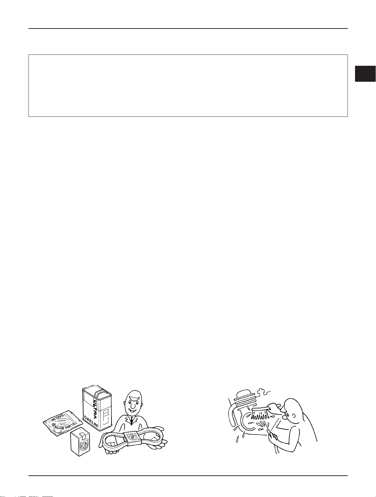
Service Rules
1. Parts and lubrication oil must be DAELIM genuine or
recommended parts.
2. Before maintenance, remove deposit or dust from the
chasis.
Page 7
1-2
Service Information
9. Check to see if the rubber part is worn out when
removing it and replace it if necessary. Some rubber part
is weak to gasoline and kerosene, so pay attention not to
soak with gasoline or oils.
10. Recommended grease must be applied to or filled in
the specified place.
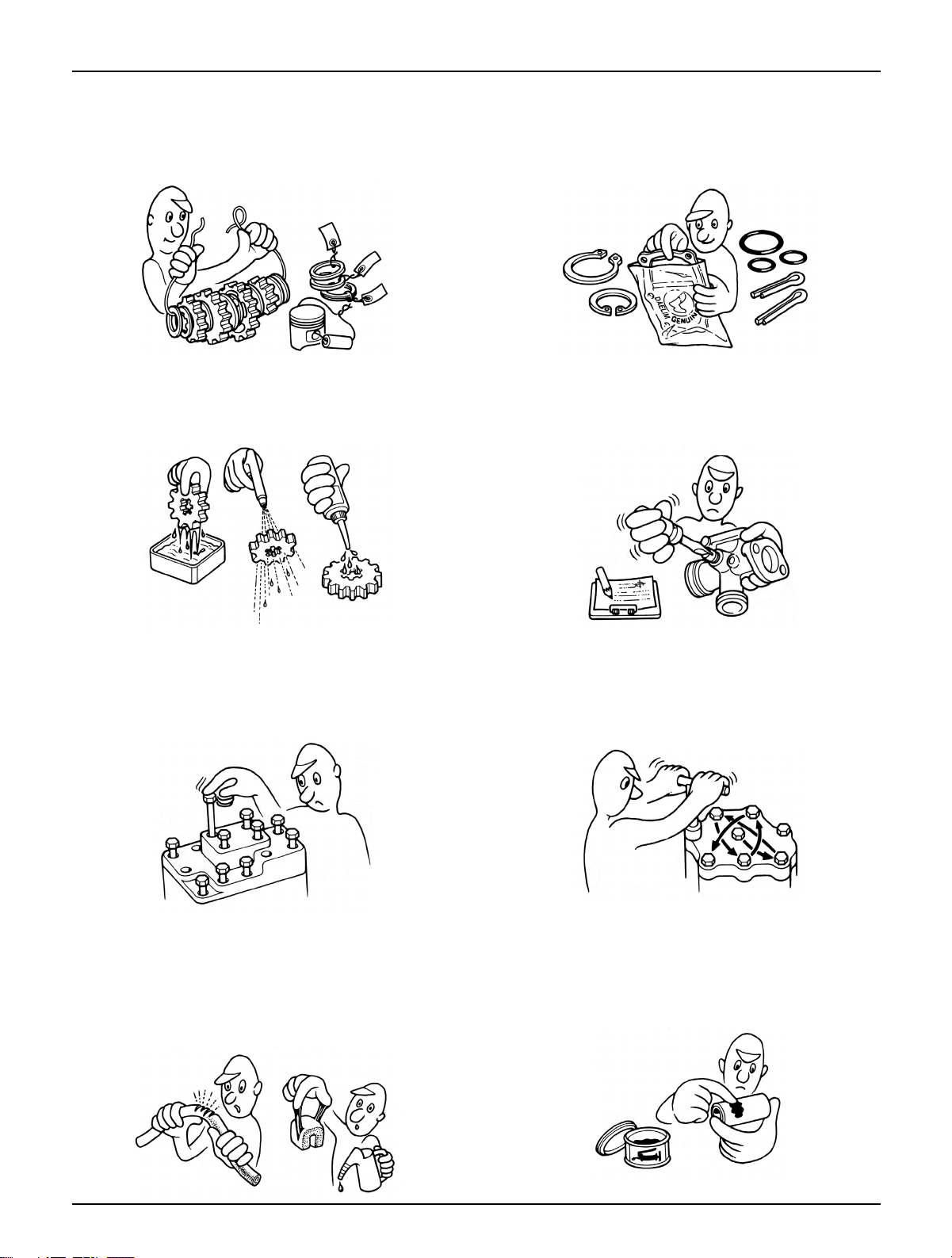
7. Align the bolts to uniform the tightening points before
tightening them when you don’t know the bolt length.
8. Bolts, nuts and pieces must be tightened from the bigger
diameter to the smaller one, from inside to outside and
diagonally with the specified torque.
5. Clean the parts after the overhaul and before the test and
remove the cleaning oil with compressed air. Apply oil
to seal face during installation.
6. Check necessary place and measure necessary data
during installation. When installing, return to the state
before removing.
3. Store the parts of each system discriminatively to install
each part in the right place.
4. After removing gasket, O-ring, piston pin clip and cotter
pin, always replace them with the new one. When
removing the snap ring, it can be easily missed after
transformation or installation.
Page 8
1-3
Service Information
11. Maintenance needed to use the specialized tools must
performed with the right tool.
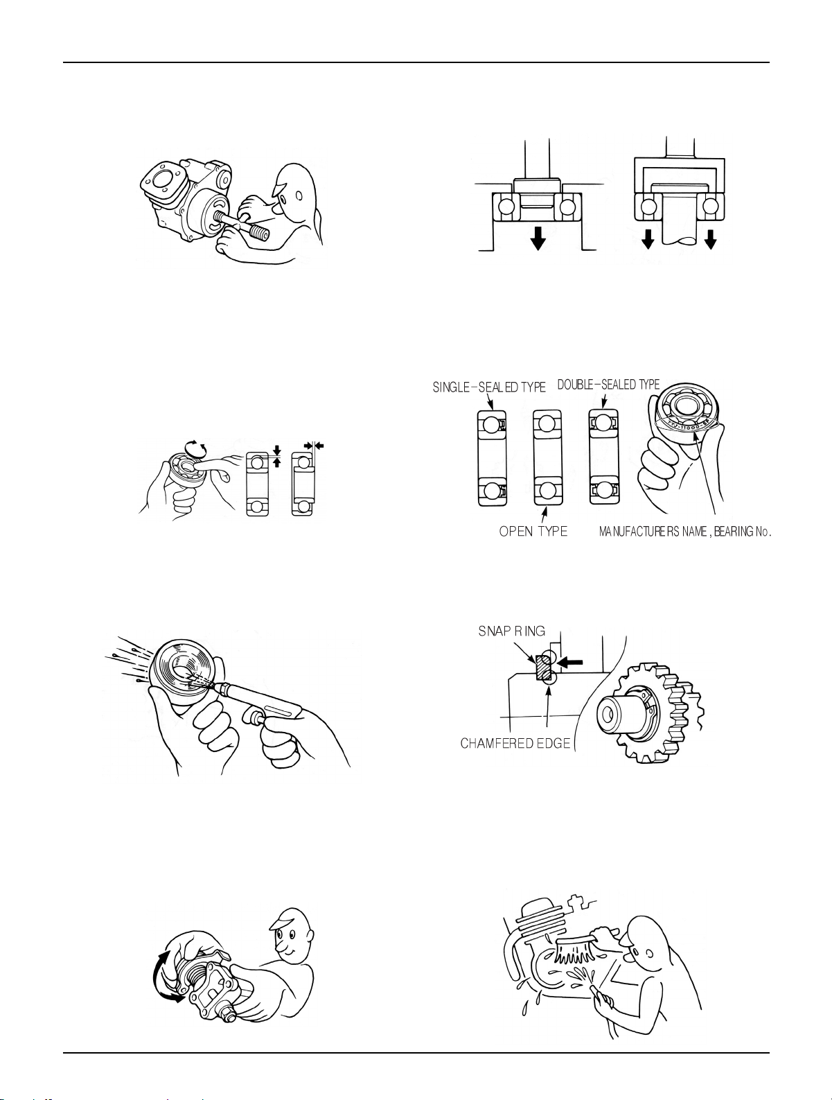
12. Never reuse the ball bearing removed with the ball
applied pressure when removing press-fitted the
bearing.
13. Check the smooth rotation of inner or outer race of the
ball bearing by rotating it manually.
Replace the ball bearing having excessive axial/
longitudinal hanging.
Wipe the ball bearing likely to have hanging with
cleaning oil.(except double-sided sealed type ball
bearing)
Replace the ball bearing of which press-fitted part is
slacked at the case or shaft.
14. Pay attention to installation direction in case of the
single-sided sealed ball bearing. Install the opendirection or double-sided sealed bearing in the way
that the face marked with manufacturer and size
should direct to the outer axle.
15. When blowing the ball bearing with compressed air
after cleaning, keep the race from rotating. High speed
rotation of the race may damage the bearing. Prior to
installation, apply oil or grease to the bearing.
16. Install the snap ring so that chamfered side directs to
the load-applied side. After installation, check the
proper installation by rotating the snap ring.
17. Check each part for proper tightening and operation
after installation.
18. The brake fluid and coolant can damage the painted
plastic or rubber parts. Keep these parts from
contacting with them and wash these parts with water
in case of contact.
’
Page 9
1-4
Service Information
21. Keep the pneumatic system interior or the engine
interior from the infiltration of dust.
22. Install the gasket mounted in the contact surface of
each case of the engine while removing gasket
material completely. Remove damaged contact surface
by wiping with the oil stone equally.
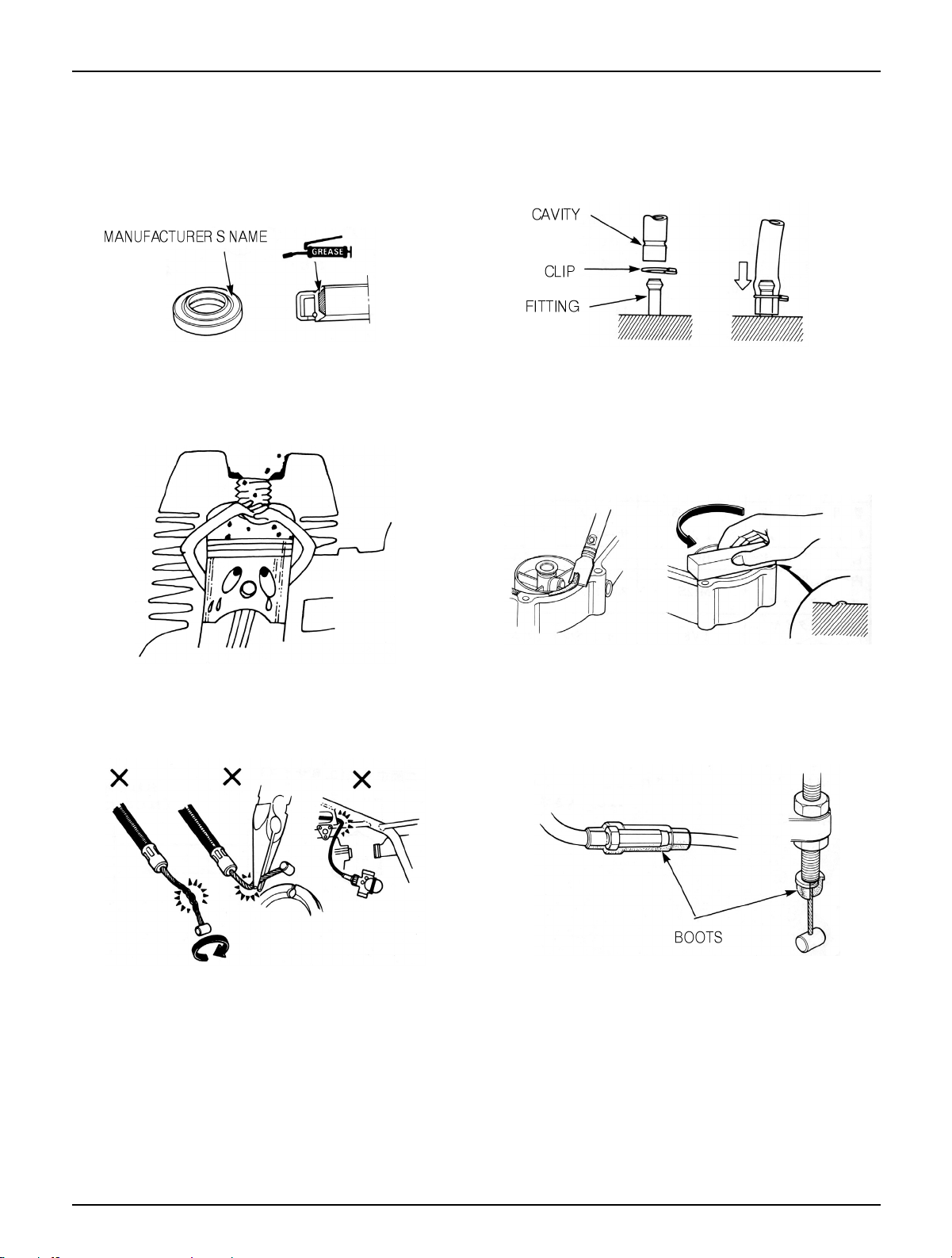
19. Install the oil seal so that the manufacturer marked
surface directs outer surface.(direction not covered
with oil)
Pay attention not to bend or damage the lip
Apply the grease to the lip
20. Connect the tube until the tube fully inserted in the
joint. Install the clip if it is supplied. Replace the tube
having slacked end.
23. Pay attention not to bend the cable excessively.
Transformed or damaged cable may cause malfunction
or damage.
24. Install the boots with the installing groove by inserting
the boots into the groove.
’
Page 10
1-5
Service Information
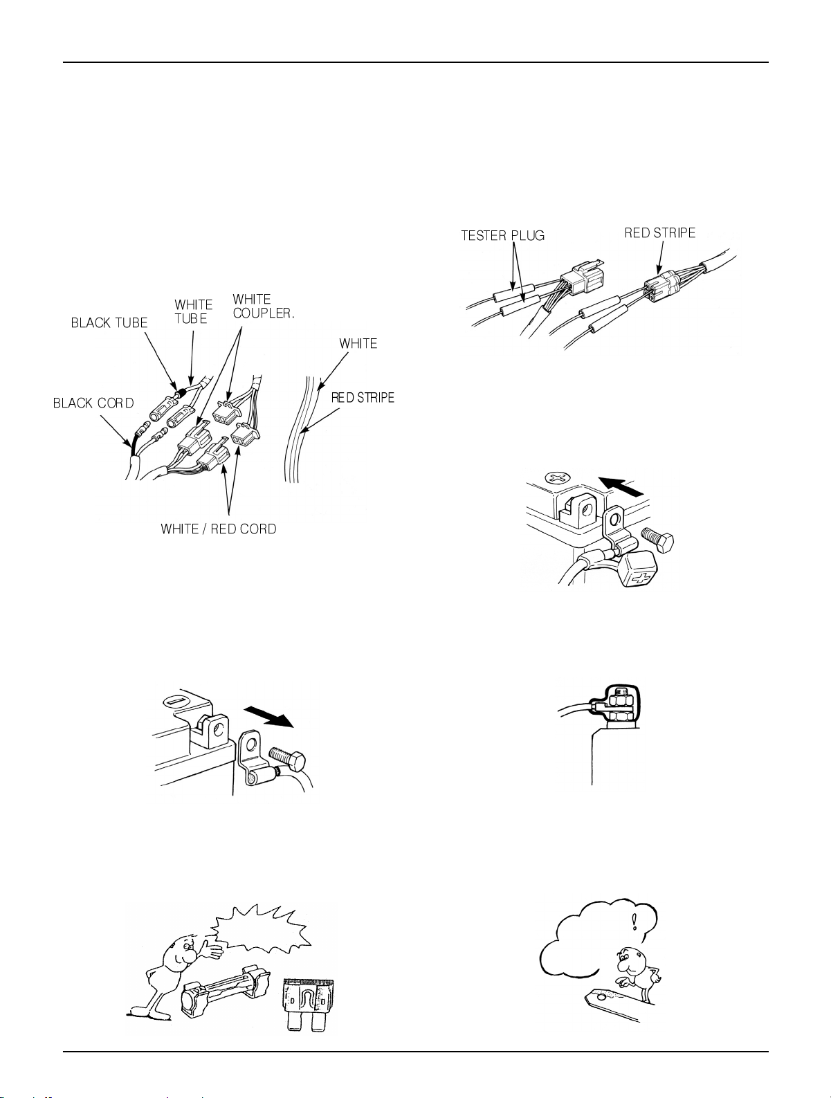
Each cord must be connected depending on its color.
When connecting different cord, attach color tube
around the connector. Connect the coupler to the
connector with same color and same pin number.
Identify the two-colored cord by main color first and
then spriped color .
When measuring voltage or resistance of the cord
terminal using tester, contact the tester plug behind of
the coupler. Pay attention not to open the cord terminal
and contact the tester plug from the front of the coupler
in case of water-proof coupler.
Recheck the condition of contact, securing and
continuity of each part after maintenance.
When connecting the battery, the plus terminal must be
connected first.
After connecting the terminal, apply the grease to the
terminal.
When disconnecting the battery, the minus terminal
must be disconnected first.
Make sure that the tool such as spanner do not contact
with the frame.
Connect covers to the terminal after maintenance.
If the fuse is short-circuited, find out the cause and
repair. Replace with the fuse having the specified
capacity.
If there is rust in the terminal, remove the rust with sand
paper prior to connecting.
Caution when Wiring
VALIDATION
OF CAPACITY!
REMOVE
THE
RUST!
Page 11
1-6
Service Information
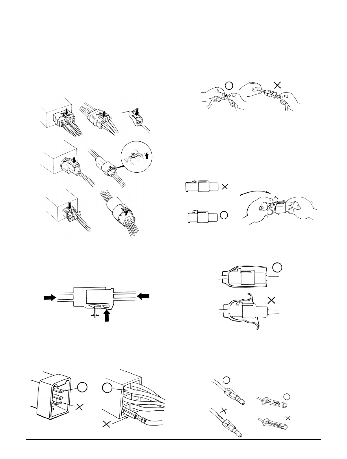
Insert the lock of the coupler until the lock is fully
secured.
Turn off the main switch before connecting/dis-
connecting.
Release the lock to disconnect the lock of the coupler.
The lock of the coupler has two types according to
releasing method(press type and pull type) so release it
properly according to the shape.
- Typical releasing method of the coupler is illustrated in
the following.
When disconnecting the coupler, disconnect it while
holding the coupler body. Pull while holding the wire
harness cord and do not remove the coupler connection.
Release the lock by inserting the coupler slightly and
then narrowing connection to remove the coupler.
Pay attention not to damage the vinyl cover of the
coupler.
Check to see if there is bended terminal and secure it to
avoid disconnecting.
If the wire harness coating is damaged, repair by
winding vinyl tape or replace it.
Prior to connecting the connector, make sure that the
cover is not damaged and the mess terminal is not
opened.
Page 12
1-7
Service Information
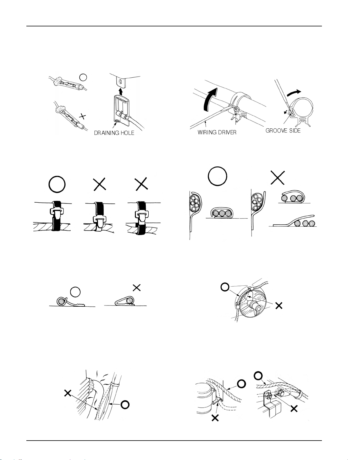
Wire band must be secured firmly in the specified
location of the frame. In case of aluminium band, secure
the wire harness to the coated part.
Secure the wire harness firmly using the clamp.
Insert the connector until the vinyl cover is fully inserted
into the terminal.
The opening of the vinyl cover must face at the ground
direction but in case of the plain connector, the draining
opening must face at the sky direction.
When removing T-start, broaden the groove of T-start
using the wiring driver and release the torque.
Connect the harness and the hose to T-start and then
insert until the groove is locked.
When removing T-start from the frame, replace it with
the new one.
In case of the weld clamp, do not clamp in the welded
part.
When clamping the wire harness, make sure that the
harness is not contacted with the shaft or rotating part.
When clamping the wire, pay attention not to contact
with hot part.
The wire harness must be routed without contacting
with the end of the lamp or any sharp edge.
The wire harness must be routed without contacting
with the end of the bolt or the piece.
Page 13

1-8
Service Information
If necessary, lock the wire harness properly. When mounting parts, make sure that the wire harness
is not pressed by the parts.
In case that the wire harness is contacted with the end or
the sharp edge, protect both parts with tube or tape.
The wire must not hang down or be pulled excessively.
Do not twist the wire harness. Wire the wire harness not to be pulled or expanded
when the handle is turned to the right or the left
completely. Avoid excessive bending or chewing and
interference with the engine.
Prior to using the tester, please read the manual care-
fully and understand the contents.
When testing the resistance of the tester, the zero
adjustment must be performed before testing.
Do not drop or throw the parts especially semiconductor
contained parts because these parts may be damaged by
the impact of the drop.
NOT TO
PULL!
Is this
measurement range or
configuration in accord
with the manual?
Page 14
Service Information
1-9
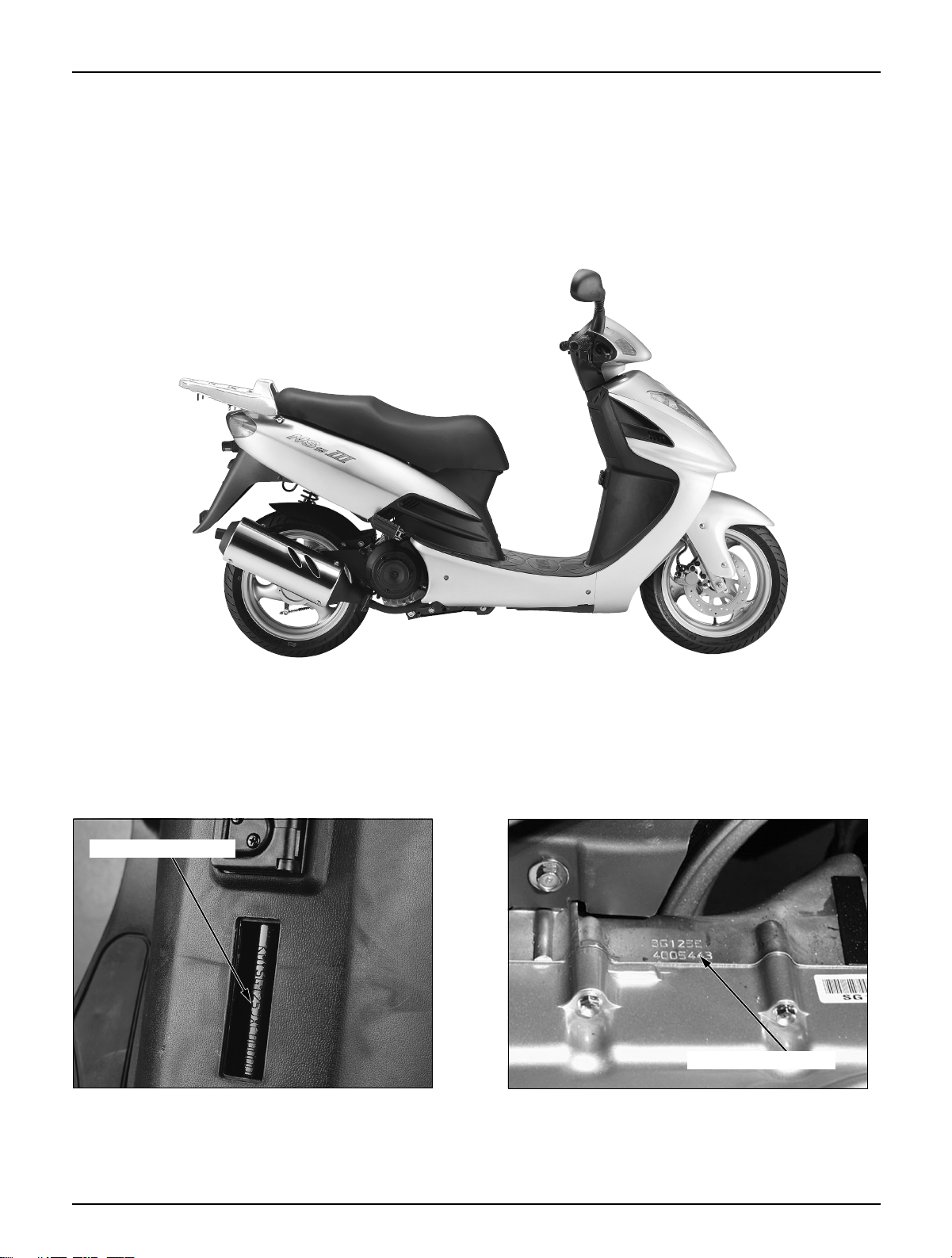
Identification Numbers
Frame serial number
Engine serial number
FARME SERIAL NUMBER LOCATION
The frame serial number is stamped on the front
central part of the frame.
ENGINE SERIAL NUMBER LOCATION
The engine serial number is stamped on the central
part of the left crankcase.
Page 15

Service Information
1-10
Item Specifications
Overall length 1,970mm
Overall width 700mm
Overall height 1,110mm
Dimensions Wheel base 1,350mm
Seat height 765mm
Ground clearance 130mm
Dry weight 110kg
Curb weight 240kg
Type Underbone
Front suspension/stroke Telescopic/97mm
Rear suspension/stroke Swing arm/74mm
Front tire size/type 120/70-13/Tubeless
Rear tire size/type 130/60-13/Tubeless
Tire Pressure 1 person Front 1.75kg/㎠(175kPa)
Rear 2.00kg/㎠(200kPa)
Frame 2 person Front 2.25kg/㎠ (225kPa)
Rear 2.25kg/㎠ (225kPa)
Front brake Hydraulic disk
Rear brake Drum brake
Fuel tank capacity Full capacity 7.5ℓ
Reserve capacity 1.2ℓ
Caster angle 25
○
Trail 84.7㎜
Front fork oil capacity 80㎤
Type Oil cooled/air cooled 4 cycle SOHC engine
Cylinders/Arrangement 1(Single cylinder), front angle 80
○
Bore and stroke 56 ×50.7 mm
Displacement 124.9㎤
Compression ratio 10.8 : 1
Valve train SOHC chain drive
Oil capacity 1.1ℓ After disassembly
0.75ℓ After Oil filter change
Engine 0.8ℓ After Oil change
0.9ℓ
After Oil change with Oil in the Oil hose removed
Lubrication system Forced pressure splash type
Air cleaner type Wet sump
Cylinder compression 13.8kg/㎠
Intake valve: Open 5
○
BTDC
Closed 14
○
ABDC
Exhaust valve: Closed 18
○
BBDC
Closed 1
○
ATDC
Valve clearance(cooling-off period)
intake 0.12 ± 0.02 ㎜
Exhaust 0.12 ± 0.02 ㎜
Specifications
Page 16

Service Information
1-11
Item Specifications
Type/Venturi bore CV type(vacuum)24.2mm
Model mark BDS 26 -112
Choke type Autoby-starter
Carburetor Main jet #95
Pilot screw initial setting 1 and 1/2 trust out
Float level 13 mm
Idle speed 1,800±100(rpm)
Clutch type Automatic Transmission
Drive Train Primary reduction 3.231(42/14)
Secondary reduction 2.786(39/14)
Ignition system C.D.I. lgnition
Ignition timing F mark 15
○
BTDC/1,800(rpm)
Full advance 19
○
AC generator capacity 125W/5,000(rpm)
Battery type/capacity Closed type (MF)12V 8AH
Spark plug CR8EH-9
Spark plug gap 0.8-0.9mm(0.031-0.035in)
Electrical Fuse capacity 15A
Systems starting system Kick/starter motor
Headlight(high/low) 12V 35/35W
Position light 12V 3.4W
Turn signal light(Fr/Rr) 12V 10W×4
Tail/stop light 12V 21 / 5W
High-beam indicator 12V 3.4W
Turn signal indicator 12V 3.4W×2
Speedometer lamp 1.7W×2
Trunk lamp 1.4W×1
Page 17
Service Information
1-12
Item Q’ty Thread dia(mm)
Torque value
Remarks
kg.m(N.m,ft-lb)
Oil filter cap 1 20 1.5(15, 11)
Valve adjust screw lock nut 4 5 1.1(11, 8)
Kick starter pedal bolt 1 6 1.2(12, 8)
Flywheel bolt 1 12 5.5(55, 40) Apply engine oil
Drive face bolt 1 12 5.5(55, 40)
Clutch outer bolt 1 12 5.5(55, 40)
Cam chain tensioner pivot bolt 1 8 1.0(10, 7)
Spark plug 1 12 1.2(12, 9)
Cam sprocket bolt 2 6 1.2(12, 9) Apply engine oil
Camshaft holder nut 4 8 2.0(20, 14) Apply engine oil
Cam chain tensioner mounting bolt 2 6 1.2(12, 9)
Cam chain tensioner sealing screw 1 6 0.4(4, 2.9)
Cylinder head cover bolt 4 6 1.0(10, 7)
Transmission cover bolt 8 6 1.2(12, 8)
Transmission cover drain bolt 1 8 1.0(10, 7)
Transmission cover check bolt 1 8 0.9(9, 6)
Cooling fan bolt 3 6 1.0(10, 7)
Starting clutch nut 1 22 9.5(95, 67)
Starter motor terminal nut 2 6 0.9(9, 6)
Radiator hose eye joint bolt 4 12 3.2(32, 23)
Radiator hose nut 2 14 3.2(32, 23)
Torque Values
Engine
Item Q’ty Thread dia(mm)
Torque value
Remarks
kg.m(N.m,ft-lb)
Steering stem lock nut 1 26 7.5(75, 55)
Steering top thread nut 1 26 0.3(3, 2) Initial torque
Handle post nut 1 10 6.0(60, 44)
Front fork bottom bridge bolt 4 10 7.5(75, 55)
Front fork socket bolt 2 8 2.0(20, 14)
Apply locking agent
Front axle nut 1 12 5.5~6.5(55~65, 40~47)
Front brake disk bolt 3 8 3.9(39, 28)
Apply locking agent
Ignition coil bolt 1 5 0.5(5, 4)
Rear axle nut 1 14 6.0-8.0(60-80, 43-58)
Engine hanger nut 2 10 7.3(73, 53)
Engine hanger plate bolt 6 10 2.7(27, 20)
Frame
Page 18
Service Information
1-13
Item Q’ty Thread dia(mm)
Torque value
Remarks
kg.m(N.m,ft-lb)
Brake caliper bracket bolt 2 8 2.7(27, 20)
Brake caliper bleeder valve 1 8 0.6(6, 4.3)
Brake caliper slide pin (socket bolt)
1 8 2.3(23, 17)
Brake caliper pin bolt 1 8 1.8(18, 13)
Apply locking agent
Brake pad pin bolt 2 8 1.8(18, 13)
Master cylinder reservoir cap 4 4 0.13(1.3, 0.94)
Brake hose bolt 2 10 3.5(35, 25)
Brake lever pivot bolt 1 6 1.0(10, 7)
Brake lever pivot lock nut 1 6 1.0(10, 7)
Rear shock-absorber upper bolt 1 10 2.7(27, 20)
Rear shock-absorber lower bolt 1 10 4.0(40, 29)
Rear shock-absorber damper rod lock nut
2 10 3.8(38, 27)
Apply locking agent
Torque values listed above are for specific tightening points. Torque values for other items are listed in the
following table.
SH(Small Head): Indicates 6mm bolt of 8mm flange head.
Item
Torque Value
Item
Torque Value
N.m Kg-m ft-lb N-.m Kg-m ft-lb
5mm bolt, nut 5 0.5 4 5mm screw 4 0.4 3
6mm bolt, nut 10 1.0 7 6mm screw 9 0.9 7
8mm bolt, nut 22 2.2 16 6mm flange bolt, nut 9 0.9 7
10mm bolt, nut 35 3.5 25 6mm flange bolt, nut 12 1.2 9
12mm bolt, nut 55 5.5 40 8mm flange bolt, nut 27 2.7 20
10mm flange bolt, nut 40 4.0 29
Page 19
Service Information
1-14
Symbols/Abbreviations
The following symbols are used in this manual to represent job-related warnings or cautions.
The following symbols indicate oil adding, oil change, or parts.
The following abbreviations are used in this manual.
ASS’Y Assembly
L. Left
R. Right
Symbol Meaning
Add oil. If there is no specific oil indicated, use the designated or recommended engine oil.
Apply grease
(⇨ 3-1) Indicates reference page.(example: Refer to page 3-1)
Symbol Meaning Symbol Meaning
OIL
GREASE
WARNING
NOTE
Indicates dangerous area. Serious
accident may result if instructions
are not followed.
Indicates important work. Minor
injury or vehicle part damage may
result if instruction are not followed.
Indicates general safety matters.
Provides safety and appropriate
handling procedures.
CAUTION
Page 20
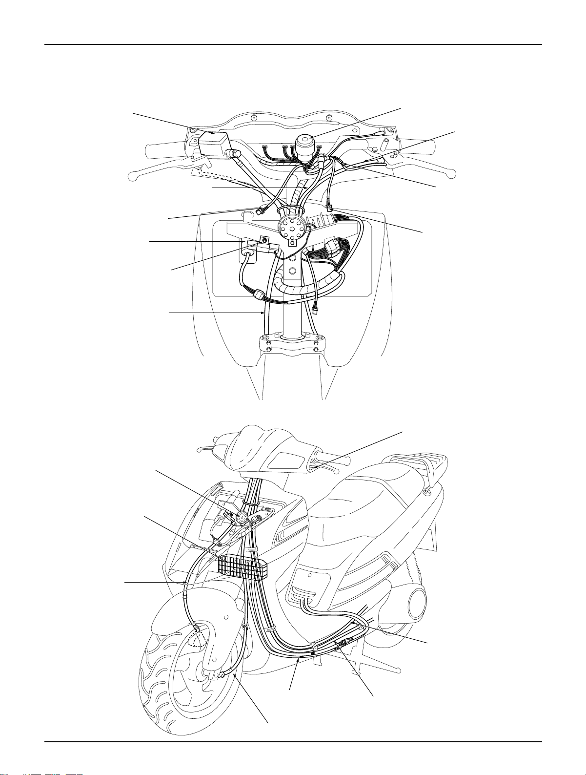
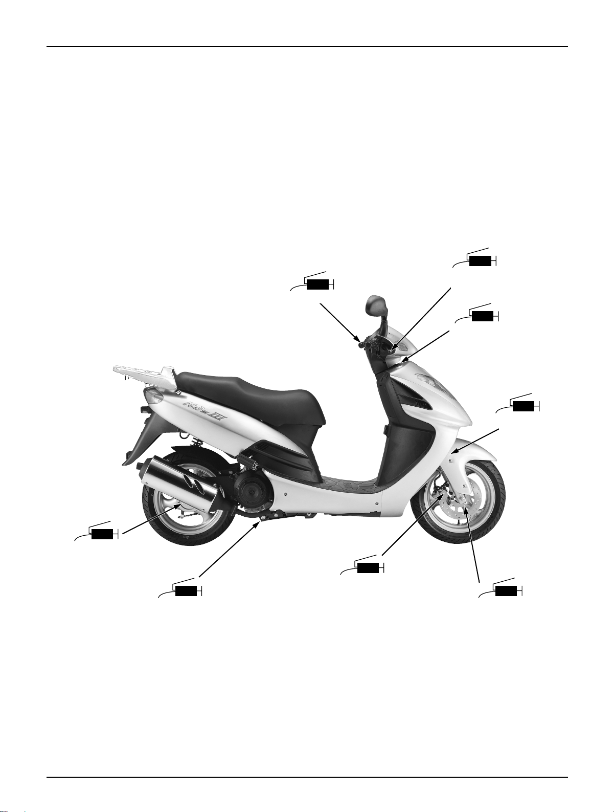
Wiring Diagram
Service Information
1-15
Rear brake cable
Winker relay
Stop switch connector
Front winker connector
Front brake hose
Horn
Radiator
Packing lever
Front brake hose
Speedometer cable
Rear brake cable
Radiator hose
Throttle cable
Main switch
Resister(excepted
some countries)
Front winker connector
Speedometer Cable
Front brake master
cylinder
Page 21
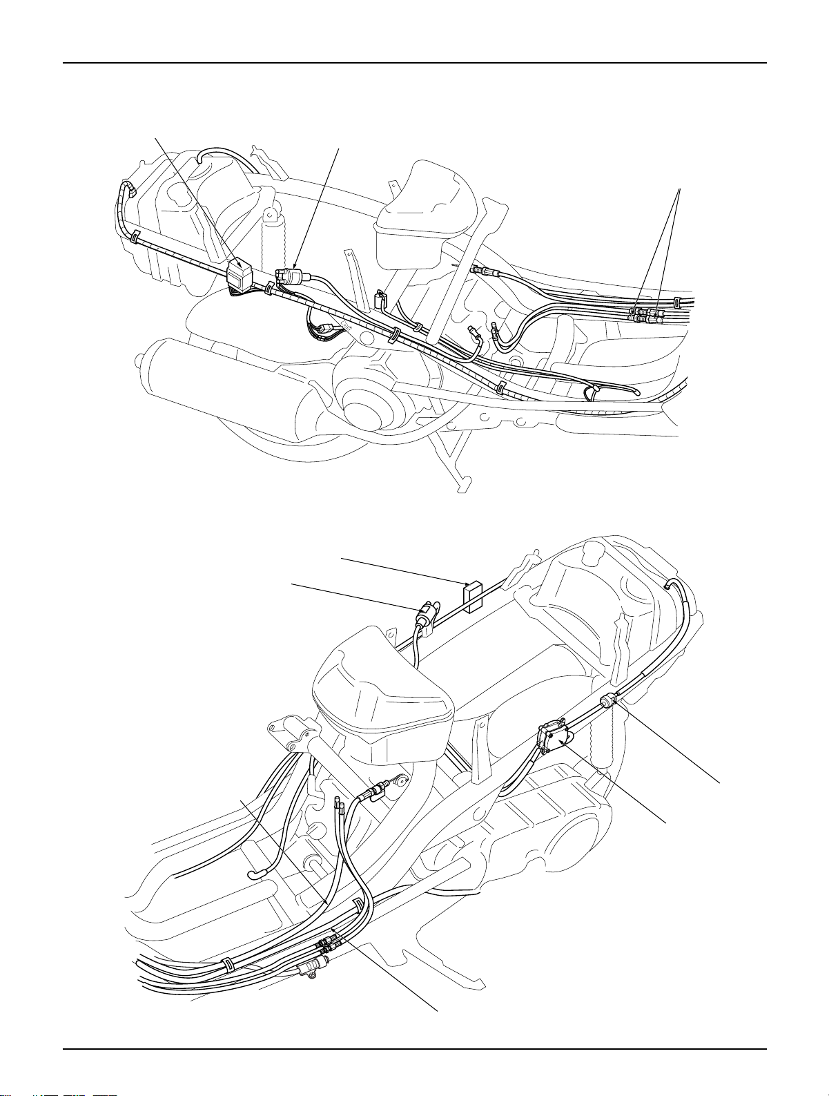
Service Information
1-16
CDI unit
Ignition coil
Radiator hose
CDI unit
Ignition coil
Throttle cable
Rear brake cable
Fuel pump
Fuel filter
Page 22
Lubrication
2-1
2. Lubrication
Service Information
General Safety
WARNING
1. The exhaust gas contains poisonous substance. Do not keep engine idling in a closed or poorly ventilated
place for a long period of time.
2. Used engine oil may cause skin cancer if repeatedly left in contact with the skin for prolonged periods. It is
desirable not to handle used oil frequently; however, wash your hands thoroughly with soap and water
immediately after handling the used oil.
3. The oil pump can be serviced without removing the engine from the frame.
Engine Oil
API service classification: SE, SF, SH grade
Oil
Viscosity: SAE10W-30
Recommendation
(Use appropriate type of oil with viscosity
satisfying the atmospheric temperature
In your riding area based on the table shown
on the right side.)
1.1ℓ(After disassembly)
Oil capacity
0.75ℓ(After Oil filter change)
0.8ℓ(After Oil change)
0.9ℓ(After Oil change with Oil in the Oil hose removed)
20·20W
10W
30
40
20W 50
20W 40
10W 40
10W - 30
–10 0 10 20 30 40℃
Pump body clearance 0.08–0.17(0.003-0.007) 0.23(0.009)
Rotor tip clearance 0.03–0.13(0.001-0.005) 0.18(0.007)
Pump side clearance 0.04–0.09(0.002-0.004) 0.12(0.005)
Oil filter screen cap 1.5kg–m, (15N.m, 11ft–Ib)
Oil filter cover bolt 1.1kg–m, (11N.m, 8ft–Ib)
Oil pump mounting bolt 1.1kg–m, (11N.m, 8ft–Ib)
Oil drain plug bolt 2.5kg–m, (25N.m, 18ft–Ib)
Item Standard value Tolerance
Oil Pump
Torque Values
Unit: mm(in)
2
Service information 2-1
Troubleshooting 2-2
Engine Oil Level Check 2-3
Engine Oil Change 2-3
Oil Filter Element Change 2-4
Oil Pump 2-4
Radiator 2-7
Lubrication Points 2-9
Page 23

Lubrication
2-2
Troubleshooting
Oil level too low - high oil consumption
● External oil leaks
● Worn piston rings
● Worn valve guide or seal
Oil contamination
● Oil or filter not changed often enough
● Head gasket faulty
● Worn piston rings
Low oil pressure
● Oil level now
● Pressure relief valve stuck open
● Plugged oil pick-up screen
● Oil pump worn
● External oil leaks
High oil pressure
● Pressure relief valve stuck closed
● Plugged oil filter, gallery, or metering orifice
● Incorrect oil being used
No oil pressure
● Oil level low
● Oil Pump drive gear broken
● Oil pump faulty
● Internal oil leakage
Page 24
Lubrication
2-3
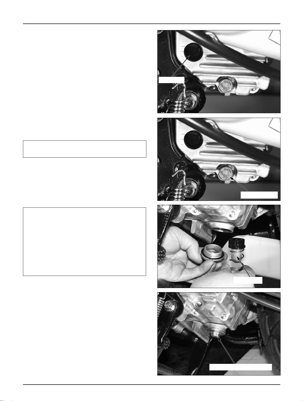
Engine Oil Level Check
● Erect the motorcycle on the main stand.
● Warm up the engine to heat the engine oil to an
appropriate level.
● Stop the engine, and check the oil level line on the
sight-glass installed on the L. crank case cover.
● If the oil level is between the lower and higher
sight-glass oil level line, oil level is satisfactory. If
the oil level is below or near the lower level mark,
add the recommended engine oil.
Engine Oil Change
NOTE
●
Loosen the oil drain plug bolt and drain engine oil.
● Operate the kick starter arm several times to
remove the remaining oil from the engine.
● Tighten the oil drain plug bolt.
Torque value: 2.0-3.0kgf··m
CAUTION
It is extremely important to replace oil filter or
clean the oil filter screen at the first maintenance
interval (after 1,000Km).
Clean the oil filter screen every 4,000Km.
Clean the filter screen with fresh cleaning oil.
Check the hole cap O-ring for satisfactory condition.
Tighten the hole cap with specified tightening
torque.
Torque value: 1.5kgf··m
● Loosen the special screw, remove the plug
maintenance cover.
● Fill the recommended oil after opening oil filter
cap of cylinder head cover.
Oil Capacity: 1.1ℓℓ(After disassembly)
0.75ℓℓ(After Oil change)
0.8ℓℓ(After Oil filter change)
0.9ℓℓ(
After Oil change with Oil in
the Oil hose removed
)
● API service classification: SE, SF, SH grade
● Start the engine and keep it idle for a few minutes.
● Stop the engine and check the oil level. If the oil
level is low, add the recommended engine oil.
● Check on oil leaks.
To completely and rapidly drain engine oil, warm
up engine and erect the motorcycle on its side stand.
Filter screen
Sight-glass
Drain plug bolt
Tappet adjusting hole cap
Page 25
Lubrication
2-4
Oil Filter Element Change
● Drain engine oil. ( 2-3)
● Remove the oil filter cover bolts, filter cover, filter
element and spring.
● Change the oil filter element with a new one.
● Check the relief valve inside the oil filter cover for
satisfactory operation.
● Check if the oil filter seal is in good condition.
● Assemble the filter element spring and filter cover,
and tighten bolts.
Torque value: Oil filter cover 1.1kg-m(11N.m.8ft-lb)
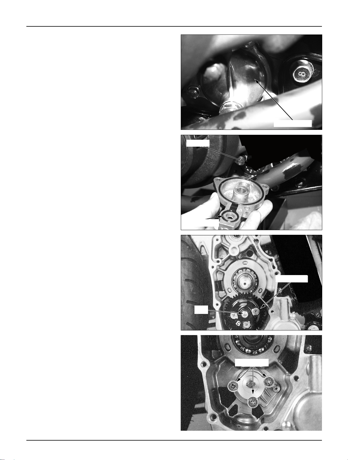
Oil Pump
● Remove the following parts:
- Luggage box (⇨ 4-5)
- Rear cushion bolt(⇨ 6-2)
- RH. floor side cover(⇨ 4-5)
- Exhaust muffler(⇨ 4-9)
- Center cover (⇨ 4-4)
- Shroud (⇨ 8-2)
- Cooling fan(⇨ 8-2)
- R. Crank cover (⇨ 8-4)
- A.C. generator (⇨ 8-2)
- Starter driven gear and reduction gear (⇨ 8-5)
- Starter clutch (⇨ 8-6)
● Loosen the oil pump drive gear setting nuts.
● Remove the oil pump drive gear.
● Remove the oil pump driven gear.
Oil filter cover
Element
Drive gear
Nut
Setting bolts
Oil filter seal
Page 26
Lubrication
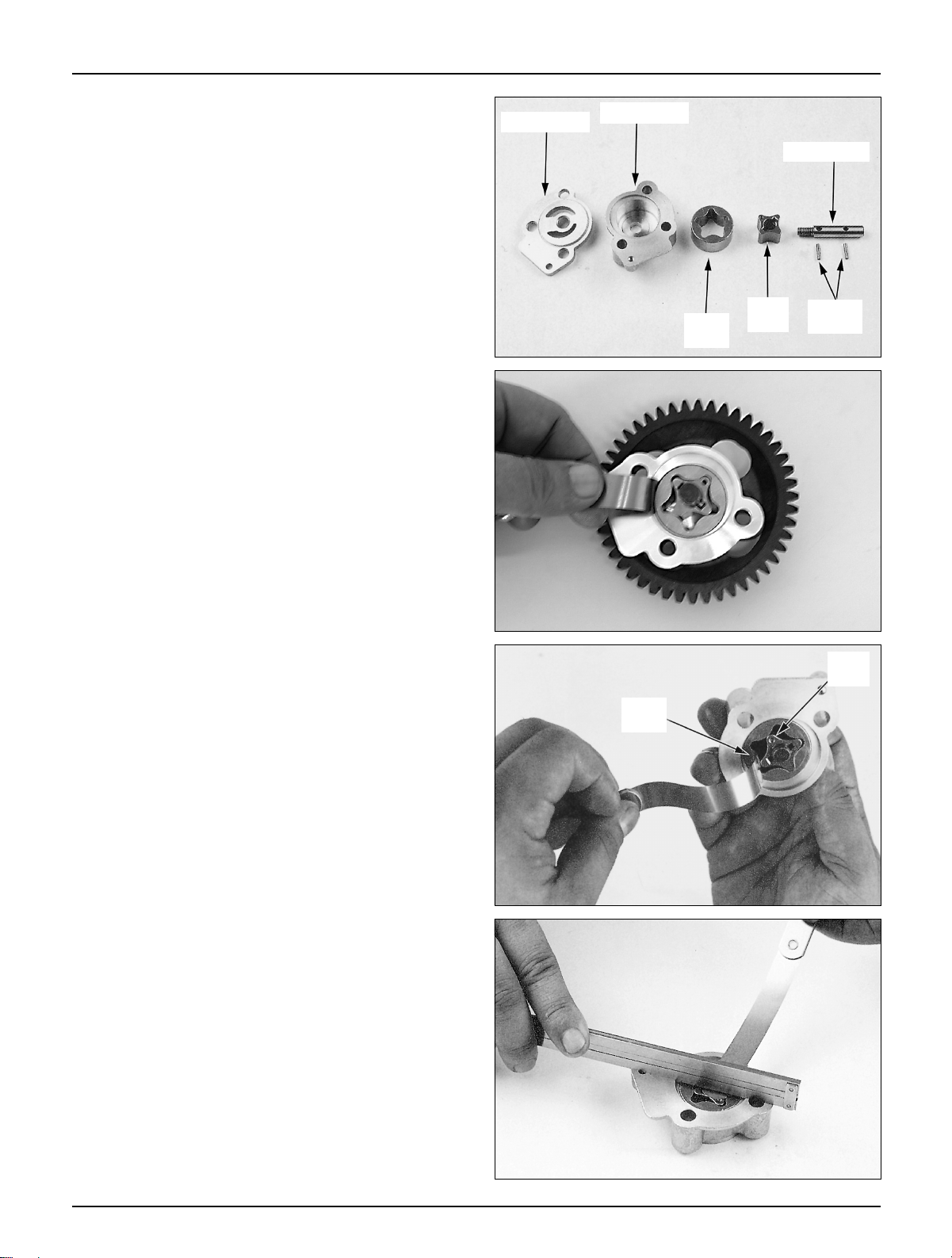
● Remove the oil pump.
● Clean the oil pump body, inner and outer rotors
with fresh cleaning oil.
● Measure the rotor tip clearance.
Service limit: 0.18mm (0.007in)
Inspection
● Assemble the inner and outer rotors to the oil
pump
● Measure the pump body clearance.
Service limit: 0.23mm (0.009in)
● Measure the pump side clearance.
Service limit: 0.12mm (0.005in)
2-5
Outer
rotor
Inner
rotor
Setting
pin
Pump shaft
Pump body
Pump plate
Outer
rotor
Inner
rotor
Page 27
Lubrication
2-6
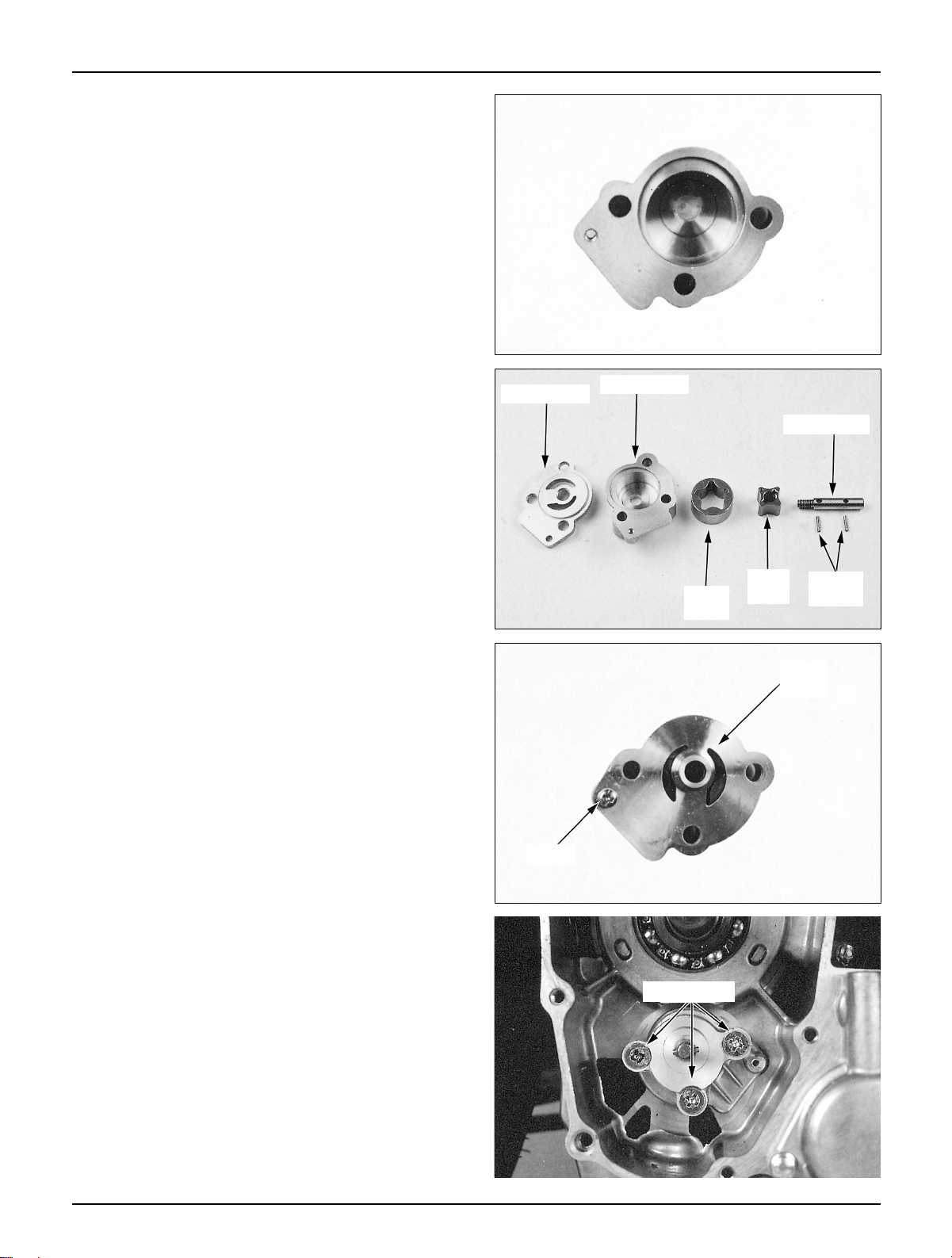
Removal/Installation
● Remove the inner and outer rotors from the
pump body.
● Clean all parts with fresh cleaning oil.
● Attach the oil pump plate to the pump body.
● Tighten screws.
Installation
● Assemble the oil pump to the R. crank case cover.
● Install the following parts.
- Oil pump drive gear and driven gear
- Starter clutch
- Starter driven gear and reduction gear
- A.C. generator
- R. crank case cover
- Shroud and cooling fan
- Center cover
- Body cover
- Luggage box
● Install the inner and outer rotors.
● Assemble the pump shaft with setting pins.
Screw
Pump
Plate
Outer
rotor
Inner
rotor
Setting
pin
Pump shaft
Pump body
Pump plate
Setting bolts
Page 28
Lubrication
2-7
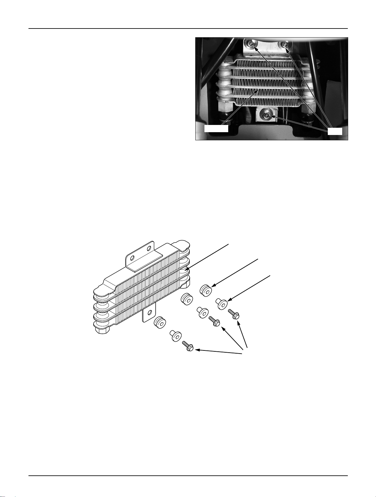
Radiator
Removal/Installation
● Remove the front wheel.
● Remove the front cover, front side cover and
inner box.
● Loosen the flange bolt(3EA), oil bolt and remove
the radiator from the main pipe bracket.
Radiator
Radiator bracket
Radiator collar
Flange bolt
bolts
Radiator
Page 29
Lubrication
2-8
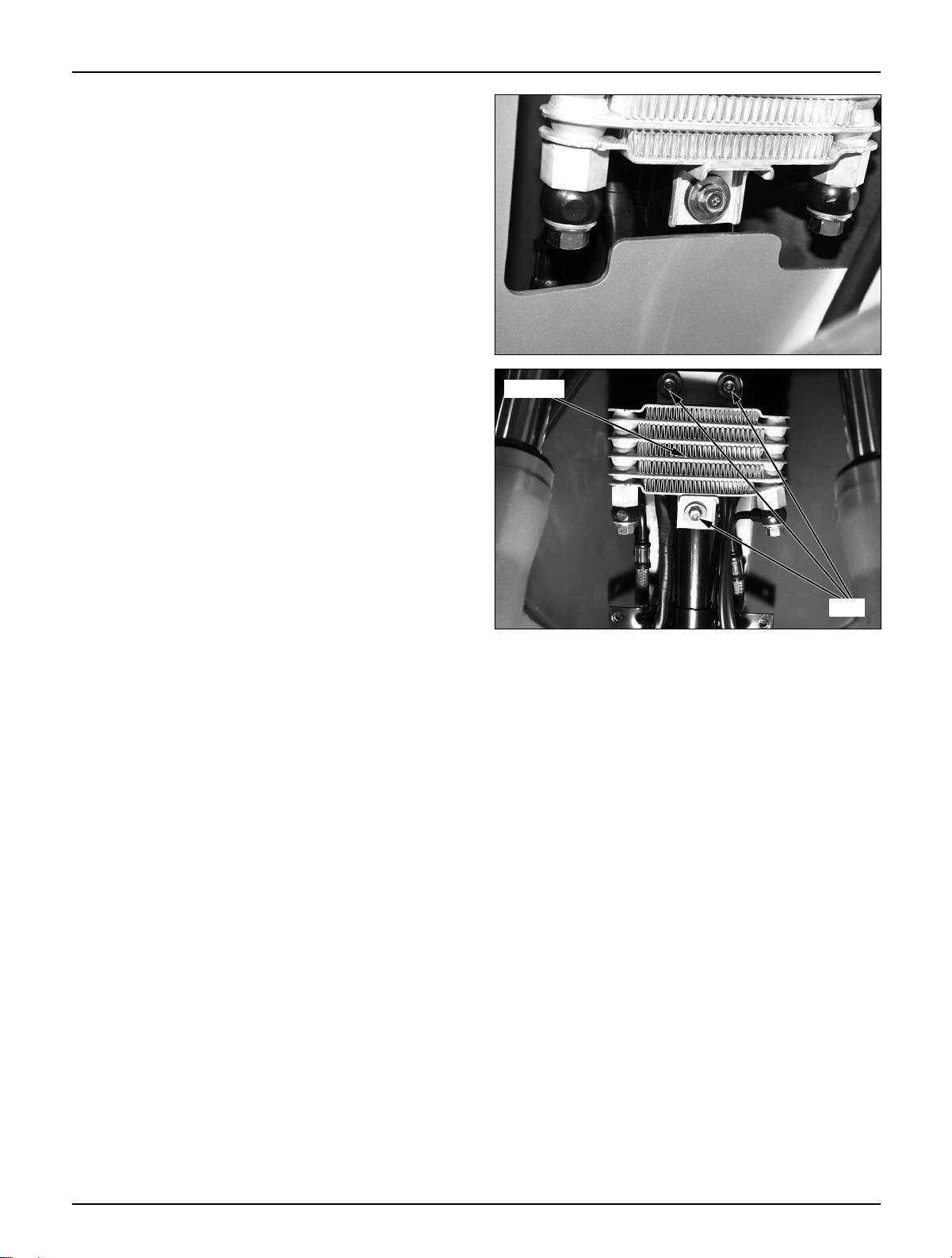
Inspection
● Check the damage or oil leaks from the radiator.
Radiator Installation
● Assemble the radiator to the main pipe bracket.
● Tighten the oil bolt.
● Install the inner box.
● Install the front side cover.
bolts
Radiator
Page 30
Lubrication
2-9
Lubrication Points
Unless specifically designated, use general grease to
lubricate the lubrication points. For sliding parts
not shown here, add oil or grease.
Control Cable Lubrication
Remove and clean the upper assembly of the throttle
cable, and apply oil. If the cable has expanded,
replace it.
Wheel
bearing
Side/main stand pivot
Brake caliper
bracket
Wheel bearing
/speedometer gear
Front fork
dust seal
grease
grease
grease
grease
grease
grease
grease
grease
Front brake
lever pivot
Setting head
bearing
Throttle grip
Page 31

MEMO
Page 32

Inspections/Adjustments
3-1
3. Inspections/Adjustments
Service Information 3-1
Regular Inspection Schedule 3-3
Fuel Line 3-4
Throttle Grip Operation 3-4
Air Cleaner 3-4
Spark Plug 3-5
Valve Tappet Clearance 3-5
Cylinder Compression Pressure
3-6
Carburetor Idling 3-6
Brake Fluid 3-7
Brake Pad/Shoe 3-7
Brake System 3-7
Brake Lever Free Play 3-8
Headlight Adjustment 3-8
Side Stand 3-8
Suspension 3-9
Bolts and Nuts 3-9
Wheels/Tires 3-10
Steering Head Bearing 3-10
Service Information
WARNING
● The exhaust gas contains poisonous substance. Do not keep engine idling in a closed or poorly ventilated
place for a long period of time.
NOTES
Driver only
Front tire 175kPa (1.75kg/㎠)
Rear tire 200kPa (2.00kg/㎠)
Cold tire pressure
Driver and
Front tire 225kPa (2.25kg/㎠)
a passenger
Rear tire 280kPa (2.80kg/㎠)
Tire size
Front tire 120/70-13(Tubeless)
Rear tire 130/60-13(Tubeless)
Min,tread depth
Front tire 4mm (0.16 in)
Rear tire 7.5mm (0.3 in)
For information on engine oil and oil filter, refer to sections 2-3 and 2-4
Stand the main stand prior to beginning work.
Throttle grip play 2–6mm(1/8-1/4 in)
Spark plug CR8EH-9
Spark plug gap 0.8–0.9mm(0.031-0.035in)
Valve clearance
IN 0.12± 0.02mm(0.005±0.001 in)
EX 0.12±0.02mm(0.005±0.001 in)
Carburetor idle speed 1,800±100rpm
Cylinder pressure 13.8kg/㎠
Specifications
Tires
3
Page 33

3-2
Inspections/Adjustments
Torque Values
Spark plug 1.1kg–m, (11N.m, 8ft–lb)
Cylinder head cover bolts 1.0kg–m, (10N.m, 7ft–lb)
Valve adjusting nuts 1.1kg–m, (11N.m, 8ft–lb)
Timing hole cap 0.6kg–m, (6N.m, 4.3ft–lb)
Tools
Wrench, 8×9mm
Adjusting wrench
Compression gauge
Page 34

Fuel line(Fuel tube) I I I I
Fuel filter R R R R
Throttle grip operation I I I I
Air cleaner C for each 1,000km Note 2
Spark plug I R I
Valve clearance I I I I
Transmission oil R
Engine oil R R R R
Engine oil filter element R R R R
Carburetor idle speed I I I I
Brake fluid I I R Note 3
Brake shoe/pad I I I
Brake system I I I I
Brake stop switch I I I
Headlight beam distance
III
Side stand I I I
Suspension I I I
Bolt and nut tightness I I
wheels/tires I I I
Steering head bearing I I
3-3
Inspections/Adjustments
Regular Inspection Schedule
Carry out pre-operation check at each scheduled maintenance period based on the information described in
the owner’s manual.
I: Inspect, and clean, adjust, lubricate or replace, if necessary.
R: Replace L: Lubricate C: Clean
Frequency
Odometer reading(Note 1)
Item
1000km 4000km 8000km 12000km
Remark
61218
Should be received by an authorized DAELIM dealer, unless the owner has proper tools and service data
and not mechanically qualified.
In the interest of safety, we recommended these items be served only by an authorized DAELIM dealer.
NOTE
1. After the odometer reading exceeds 12,000km, repeat maintenance service at intervals indicated in the table.
2. After riding in areas with high humidity or pollution, carry out maintenance service more frequently.
3. Replace every 2 years. Proper technology is required for this job.
Page 35

Inspecitions/Adjustments
3-4
Fuel Line (Fuel Tube)
● Remove the luggage box (⇨ 4-5)
● Check the fuel tube of the fuel pump connected
to the fuel tank and carburetor. If the fuel tube is
cracked, damaged or leaks, replace it.
Throttle Grip Operation
● Check if the throttle grip operates smoothly in any
steering position.
● If the throttle grip does not operate properly,
lubricate the throttle cable.
● If the throttle grip does not operate properly,
check the throttle cable for aging, damage or
kinking.
● Check the throttle grip free play.
Free play: 2~6mm(1/8~1/4in)
Air Cleaner
● Unlock the system with main key, and open the
seat.
● Loosen the 6 setting screw assembled to the air
cleaner case cover.
● Loosen the 2 setting screw assembled to the air
cleaner element.
● Remove the air cleaner element.
Fuel pump
Fuel tube
Screw
Screw
Air cleaner element
Page 36

3-5
Inspecitions/Adjustments
● Soak the element in solvent, and dry completely.
● Soak in gear oil (SAE #80-90), and squeeze firmly
to remove excessive oil.
● If the element is excessively contaminated or
damaged, replace it.
● Assemble in the reverse order of the disassembling.
Spark Plug
● Remove the plug maintenance cover.
● Remove the spark plug cap and disassemble the plug.
● Check the plug for damage, contamination or
deposits.
● If the spark plugs are severely contaminated or
damaged, replace with new ones. If the plugs can be
reused after removing only the carbon, use plug
cleaner and wire brush to clean the plugs.
● Always use a feeler gauge to check the clearance.
Genuine plug: CREH-9
Spark plug clearance: 0.8-0.9mm
Torque value: 1.1kg-m(11N.m, 8ft-lb)
NOTE
Valve Tappet Clearance
● Remove the following parts.
-- Center cover. (⇨ 4-4)
● Loosen the 4 cylinder head bolts.
NOTE
● Measure valve clearance with a feeler gauge.
Valve tappet clearance:
Intake: 0.12±±0.02mm(0.05±±0.001in)
Exhaust: 0.12±±0.02mm(0.05±±0.001in)
Carry out inspection/adjustment when the
engine is cold. (35℃/95F)
Remove the cylinder head cover.
Turn the flywheel counterclockwise, and match
the “T” mark on the flywheel with the index
mark on the R crank case cover.
The piston at this time must be at the top dead
center of the compression stroke.
First, manually tighten the plugs, and use a spark
plug wrench to tighten completely.
Cylinder
head cover
“T” mark
Wash
Squeeze
Dry
Gear oil
(#80-90)
Check
washer
for damage
Check for
cracks.
Check
gap
Squeeze
out oil
Oil
0.8~0.9mm
Page 37

Inspections/Adjustments
3-6
● Loosen the lock nut with a valve wrench, and set
valve clearance to a prescribed level by turning the
adjusting screw with a valve adjusting wrench.
● After setting clearance to the prescribed level, hold
the adjuster screw with a valve adjusting wrench,
and tighten the lock nut.
Torque values: 1.1kg-m(11N.m,8ft-lb)
Tools: Wrench 8××9mm
Adjusting wrench B
● Measure the valve clearance again.
● Install the cylinder head cover and tighten the bolts.
Torque values: 1.0kg-m(10N.m. 7ft-lb)
Cylinder Compression Pressure
● Start and warm up the engine.
● Remove the plug maintenance cover.
● Stop engine, and remove the spark plug cap and
spark plug.
● Install a compression gauge.
● Open the throttle completely, and crank the engine
with the starter motor until the gauge reading
rising.
Tool: Compression gauge
NOTE
Compression pressure: 13.8kg/cm
2
● If the pressure is low, check the following:
- Inadequate valve clearance adjustment
- Valve leakage
- Leakage from the cylinder had gasket
- Piston / cylinder worn
● If pressure is high, check the following:
- Carbon deposits on the piston head, and cylinder
head.
Carburetor Idling
NOTE
The maximum reading is usually reached within
4~7 seconds.
Verify all engine adjustments satisfy
specifications. Make adjustments, if necessary.
Heat the engine to make accurate idling inspection
and adjustment. Stand the vehicle on the main stand.
Turn the throttle stop screw and make adjustments
to prescribed idling speed.
Feeler gauge
Adjusting
wrench
Spark plug cap
Compression gauge
Throttle Stop Screw
Page 38

3-7
Inspecitions/Adjustments
Brake Fluid
● Remove the brake fluid cover.
● Check the oil level inside the front brake reservoir.
If the oil level is near the lower limit line, remove
the reservoir diaphragm and fill DOT 3 and DOT
4 brake fluid to the top limit line.
● If the brake fluid reaches the lower limit line,
check the entire brake system for leaks.
Brake Pad/Shoe
Brake pad replacement
● Check the brake pads for wear.
● If the red mark on the pad reaches the brake disc,
replace the pads.
NOTE
Brake Shoe Replacement
● If the arrow mark of the wear limit aligns with the
‘△’mark when the rear brake lever is fully
pressed, it indicates the brake lining has reached
the service limit. Replace the brake shoes.
Brake System
● Check the front brake hose for cracks or damage.
If any leaks are found, replace immediately.
● Check the brake rod for looseness or damage,
and replace it if necessary.
Brake hose
Brake caliper
Brake hose bolt
Master cylinder
‘△’ mark
Red Mark
Replace the brake pads in sets.
Page 39

Inspections/Adjustments
3-8
Brake Lever Free Play
● Check the free play after pulling the lever.
Front:10-20mm
Rear:10-20mm
Rear Brake Free Play Adjustment
● Turn the adjuster nut to adjust the free play.
● After initial adjustment, check the operation of
the rear brake light switch. Make additional
adjustments, if necessary.
Adjuster
Headlight Adjustment
● Adjust the headlight beam level by operating the
adjusting screw located on the upper side of the
front fender.
NOTE
Side Stand
● Erect the main stand.
● Pull the lower end of the side stand, and see if it
moves freely.
● If the side stand does not move smoothly, apply
grease to the pivot area.
● If the side stand moves too freely, check the side
stand spring.
● Check the axial movement of the side stand.
Adjust the beam level according to local laws
and regulations.
Improper beam level adjustment may blind on
coming drivers, or may incorrectly light the road
ahead.
Side stand
spring
Adjuster
Page 40

3-9
Suspension
NOTE
Front wheel
● Hold the brake lever, and compress the front
cushion up and down several times to check the
operating conditions.
● Check the front fork for oil leakage, parts damage
or looseness.
Rear wheel
● Compress the near cushion up and down several
times to check the operating conditions.
● Check the rear fork for oil leakage, parts damage
or looseness.
Bolts and Nuts Tightening
●Check all nuts and bolts of the frame during the
regular maintenance ( 3-3) to check if they meet
the prescribed torque value.
● Check all pins, clips, hose clamps and cable stays.
Inspections/Adjustments
Do not ride motor cycle with an unsatisfactory
suspension. Loose or worn suspension parts will
lead to deterioration in the vehicle’s safety and
operation efficiency.
F
F
● Check the side stand ignition cut-off switch ;
-Put the side stand up.
-Start the engine.
-Lower the side stand. The engine should stop as
you put the side stand down.
● If there is a problem with the system, check the
side stand swich.
Side stand
switch
Page 41

Inspections/Adjustments
3-10
● Check the tread depth at the tire center.
● If the tread depth has reached the service limit,
replace the tire.
Service limit: 4mm (0.16in)
7.5mm (0.3in)
Steering Head Bearing
NOTE
● Lift the front wheel and check if the handle moves
right and left smoothly. If the handles move
heavily, check if the cable or electric cord
interferes with the handle. If the handle moves
satisfactorily, adjust the steering head bearing.
Check the cable if it interferes with the handle
operation.
Wear indicator position mark
Wheels/Tires
NOTE
Item Front wheel Rear wheel
Driver only 1.75(175) 2.00(200)
Driver and a passenger 2.25(225) 2.25(225)
Standard Pressure kg/
㎠㎠
(kPa)
Check the tire pressure when the tires have been
cooled off. Check the tread (the part making
contact with the road surface) and side for wear,
cracks or damage. Replace damaged tires.
Tire pressure gauge
Page 42

External Parts
4-1
4. External Parts
Service Information
NOTE
● This section describes external parts removal/installation.
● Do not apply unreasonable force when disassembling covers, to prevent possible damage.
● A muffler is hot. Do not service it immediately after the engine is stopped.
Service Information 4-1
Maintenance Procedure 4-2
External Parts Removal/Installation
4-3
Muffler 4-9
Front Fender 4-10
4
Page 43

External Parts
4-2
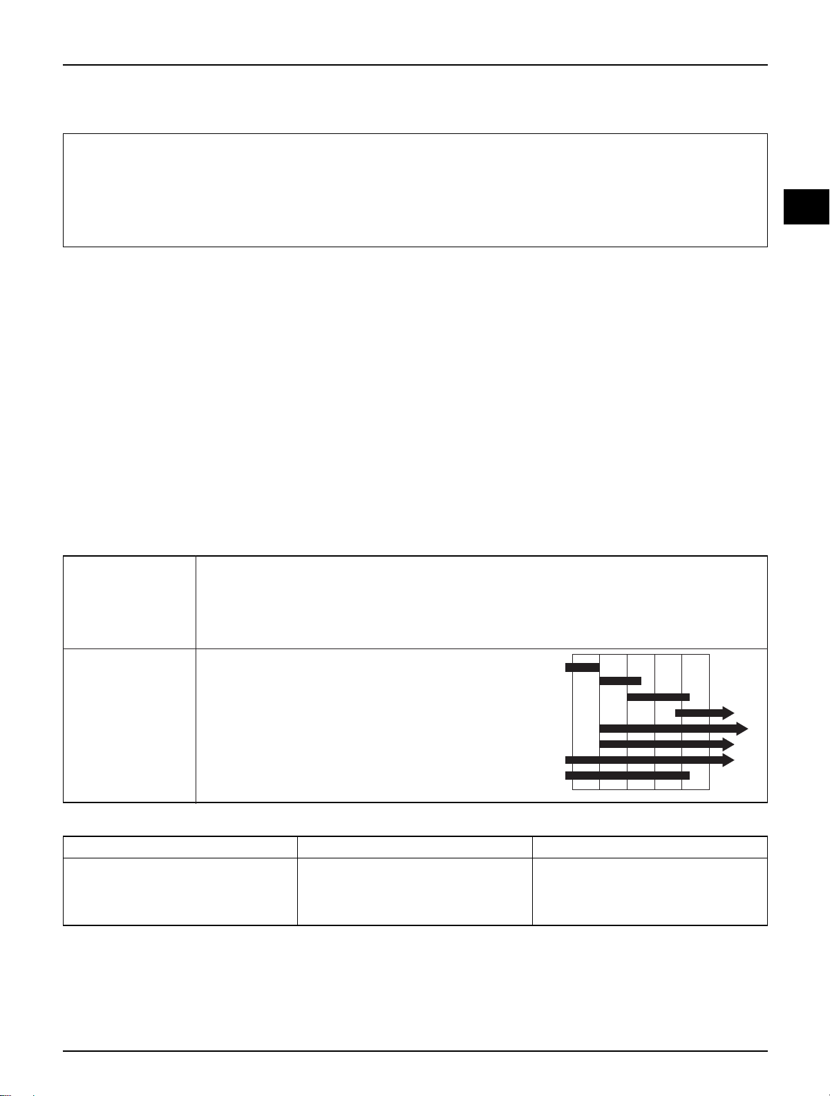
● This chart shows arrows connected in the order of disassembling covers.
① Front cover
② Inner box
③ Front side cover
④ Floor side cover
⑧
Maintenance cover
⑦ Center cover
⑨ Rear under cover
⑮
Rear handle cover
⑩ Body cover
⑫ Floor panel
⑭
Front handle cover
⑤ Luggage box
⑥ Rear carrier
⑬ Tail combination-light
⑪
Rear upper cover
Maintenance Procedure
Names of frame covers
①
⑭
③
④
②
⑮
⑦
⑧
⑫
⑤
⑥
⑪
⑨
⑬
⑩
Page 44

External Parts
4-3
Front Cover removal/Installation
● Loosen the 2 upper screws.
● Loosen the 2 lower screws.
● Pull upward and remove the front cover.
● Install in the reverse order of removal.
Front Side Cover Removal/Installation
● Remove the front fender. (⇨ 4-10)
● Remove the front wheel. (⇨ 12-5)
● Remove the 2 front lower flange bolts and the 2 upper screws.
● Remove the 2 inner box setting screws.
● Remove the front side cover.
● Install in the reverse order of removal.
Screw
Front cover
Screw
Inner box
Front side cover
Bolt
Screw
Screw
Page 45

External Parts
4-4
Inner Box
● Loosen the 2 bolts installed on the bag holder.
● Remove the bag holder.
● Open the inner box lid.
● Remove the 1 cap nut.
● Remove the 2 flange bolt installed on the floor
panel.
● Remove the 6 front side cover screws.
● Remove turn the main key cover slightly to
unlock, and remove the main key cover.
● Remove the inner box
● Install in the reverse order of removal.
Center Cover
● Loosen the 4 setting screws assembled to the
body cover.
● Remove each of the setting screws assembled to
the floor panel.
● Band inwards, and remove the center cover.
● Install in the reverse order of removal.
Screw
Front inner box
Nut
Bolt
Bag holder
Radiator
Screw
Center cover
Screw
Flug maintenance cover
Page 46

4-5
External Parts
Side Cover
● Remove the floor mat.
● Loosen the 2 screws on the side of the
R/L side covers.
● Loosen 1 each of the R/L screws
assembled to the floor panel.
● Loosen 3 each of the R/L body cover
clips assembled to the floor panel.
● Remove R/L side covers.
● Install in the reverse order of removal.
Luggage Box
● Unlock the system with the main key, and open
the seat.
● Loosen the 4 cap nuts.
● Remove the fuel tank cap.
NOTE
● Remove the luggage box.
● Install in the reverse order of removal.
● Remove the wiring of trunk lamp.
Side cover
Side stand
switch
Seat
Fuel tank cap
Luggage
box
Nut
Screw
Trunk lamp
Hinge
pin
Bolt
Bolt
Assemble the fuel tank cap after removing the
luggage box.
Page 47

External Parts
4-6
Rear Carrier
● Loosen 1 each of the R/L flange bolt set on the
body cover side.
● Loosen the 2 flange bolts set on top of the body
cover.
● Remove the rear carrier.
● Install in the reverse order of removal.
Body Cover/Rear Cover
● Remove the rear carrier. (⇨ 4-6)
● Remove the luggage box. (⇨ 4-5)
● Remove the center cover. (⇨ 4-4)
● Loosen 2 each of the R/L body cover
grill screws set with the floor panel.
● Loosen 1 each of the R/L body cover
clips assembled to the rear fender.
● Loosen 1 each of the R/L flange bolts set
on the frame body.
● Loosen 2 rear under cover setting screws,
and remove the rear under cover.
● Remove the R/L frame body cover.
● Loosen the 2 rear upper cover setting
screws.
● Install in the reverse order of removal.
Screw
Body cover clip
Rear upper cover
Frame body
cover
fuel fiter
puel pump
Rear carrier
Screw
Page 48

Tail Combination-Light
●Remove the following parts.
- Luggage box. (⇨ 4-5)
- Luggage carrier. (⇨ 4-6)
- Body cover. (⇨ 4-6)
- Rear under cover. (⇨ 4-6)
● Loosen the 2 bolts assembled
to the frame rear part.
● Loosen the 2 R/L side setting
bolts.
● Remove the tail combination-
light wiring.
● Remove the tail combination-
light
● Install in the reverse order of
removal.
4-7
External Parts
Floor Panel/Battery Cover
● Remove the center cover. (⇨ 4-4)
● Loosen 2 each of the R/L pillion step
cover setting screws of the floor mat, and
remove the floor mat.
● Loosen the 2 battery cover setting
screws, and remove the battery cover.
● Withdraw the battery wiring, and
remove the battery.
● Remove the air cleaner duct.
● Loosen the 4 setting bolts.
● Remove the side cover. (⇨ 4-5)
● Remove the 4 center cover setting
screws.
● Remove the floor panel.
● Install in the reverse order of removal.
Floor
mat
Screw
Floor panel
Bolt
Bolt
Bolt
Rear under
cover
Screw
Bolt
Battery cover
cover
Page 49

External Parts
4-8
Handle Cover
Front Handle Cover
● Loosen the 4 rear handle cover setting screws.
(1 each on R/L side, and 2 each on meter side)
● Loosen 1 front handle cover setting screw.
● Remove 1 R/L handle side cover lower screw,
and 1 each of the special upper side screws.
● Pull the front handle cover forward, and remove
the wiring.
● Remove the front handle cover.
● Install in the reverse order of removal.
Rear Handle Cover
● Loosen the 3 screws assembled to the handle bar.
● Loosen the 3 screws assembled to the meter.
● Remove the R/L side switch wiring.
● Remove the rear handle cover.
● Install in the reverse order of removal.
Rear view mirror
Bolt
Screw
Screw
Front handle cover
Handle side
cover
Meter
Rear handle
cover
Speedometer cable
Screw
Page 50

4-9
External Parts
Muffler
Removal
● Loosen the 3 flange nuts securing the EX. pipe
comp.
● Loosen the flange bolt securing the rear wheel
mud guard.
● Loosen the 2 flange bolts securing the R. crank-
case.
● Remove the EX. muffler comp.
WARNING
EX. Pipe removal
● Remove the plug maintenance cover.
● Loosen the 2 flange bolts securing the cylinder
comp.
● Remove the EX. pipe by drawing it to the ground
direction.
Installation
● Install the 2 flange bolts after securing the EX.
pipe with the stud bolt of the cylinder comp.
● Install the gasket on the EX. muffler, connect the
EX. pipe and install the 2 flange nuts temporarily.
● Install the 2 flange bolts on the R.crankcase
temporarily.
● Tighten the 3 flange nuts to install the EX. muffler
and EX. pipe.
● Install the flange bolt on the rear wheel mud
guard.
● Tighten the muffler securing 2 flange bolts to
install the R. crankcase.
● Tighten torque of the R. crankcase.
Torque: 5.5kg-m(55N.m, 40ft-lb)
WARNING
Never perform the maintenance of the muffler
right after stopping the vehicle because the
muffler is extremely hot.
When installing the gasket, replace it with the
new one.
Check to see if there is any evacuation after
installing the muffler.
Flange bolts
Flange nuts
EX.pipe
EX.pipe
Setting Bolt
Page 51

External Parts
4-10
Front Fender
● Loosen the flange bolt connecting the front
fender A and B.
● Loosen the 2 setting screws of the front fender A,
and remove the front fender A.
● Loosen 1 setting screw of the front fender B.
● Remove the speedometer cable guide.
● Remove the front fender B.
● Install in the reverse order of removal.
Fender B
Screw
Screw
Fender A
Bolt
Page 52

MEMO
Page 53

Fuel System
5-0
Fuel tank
Fuel strainer
Fuel pump
Carburetor
Page 54

Fuel System
5-1
5. Fuel System
Service Information 5-1
Troubleshooting 5-2
Fuel Tank 5-3
Air Cleaner Removal 5-4
Carburetor 5-4
Pilot Screw Adjustment 5-9
Fuel Pump Inspection 5-9
Service Information
General Safety
WARNING
● Gasoline is extremely flammable. Avoid fire in the work place, also paying particular attention to sparks.
Furthermore, the evaporated (gasified) gasoline is highly explosive. Work in a well-ventilated areas.
● Exhaust gas contains poisonous substance. Do not keep engine running for a long period of time in a
closed, or poorly ventilated area.
CAUTION
● Do not excessively bend or twist cable. Distorted or damaged cable may lead to mechanical malfunctions.
● Pay particular attention to the position of O-ring. Replace with new ones when disassembled.
● If it is desired to store a vehicle for a period longer than 1 month, drain gasoline out of the carburetor float
chamber. Gasoline left in the float chamber will be deteriorated causing the slow jet to be clogged with
deposits, and idling may become unstable.
Specifications
Fuel tank capacity: 7.5ℓ
Reserve fuel capacity: 1.2ℓ
Item Standard
Type/Throttle bore CV type (vacuum) 24.2mm
Model mark BDS 26 -112
Main jet No. #95
Pilot screw opening 1 and 1/2 returns
Pilot jet 13 mm
Idling speed 1800±100(rpm)
Throttle grip free play 2-6mm
Tool
Float level gauge
Carburetor
5
Page 55

Fuel System
5-2
Troubleshooting
Unable to start the engine
● No fuel in the tank.
● Fuel cannot be supplied.
● Fuel excessively absorbed into the cylinder.
● Air cleaner clogged.
● No spark from plugs.
Unstable idling, unsatisfactory rotation
● Unsatisfactory idling adjustment.
● Mixture too lean or rich
● Air cleaner clogged.
● Secondary air absorbed into the intake system.
● Fuel system clogged.
Mixture too lean
● Carburetor jets clogged.
● Fuel tank cap air hole clogged.
● Fuel strainer screen clogged.
● Fuel tube kinked, pressed or clogged.
● Float valve malfunction.
● Oil level too low.
Mixture too rich
● Float valve malfunction.
● Oil level too high.
● Air jets clogged.
Page 56

Fuel System
Fuel Tank
Remove
WARNING
● Remove the following parts.
- Luggage box (⇨ 4-5)
- Rear carrier (⇨ 4-6)
- Body cover (⇨ 4-6)
- Center cover (⇨ 4-4)
- Rear cover (⇨ 4-6)
- Tail combination-light (⇨ 4-7)
● Remove the fuel tube from the fuel pump.
● Remove the fuel unit wire coupler.
● Loosen the 2 top fuel tank bolts.
● Loosen the 2 bottom fuel tank bracket bolts.
● Remove the fuel tank bracket.
● Remove the fuel tank.
Installation
Install in the reverse order of removal.
NOTES
5-3
Check for gasoline leakage.
“Gasoline” mark is on the fuel tank cap.
Check this mark when filling gasoline.
Gasoline is extremely flammable. Avoid fire during
work, and pay particular attention to electric sparks.
Furthermore, the evaporated (gasified) gasoline is
highly explosive. Work in a well-ventilated areas.
Fuel Pump
Fuel Pump
Bracket
Bolt
Fuel Tank
Page 57

Fuel System
5-4
Air Cleaner Removal
● Remove the luggage box. (⇨ 4-5)
● Loosen the 2 R/L bolts attached to the frame body.
●
Loosen the band attached to the lower part(carburetor)
of the intake coupling and remove the air cleaner.
● Install in the reverse order of removal.
Carburetor
Remove
● Remove the air cleaner. (⇨ 5-4)
● Loosen the throttle cable lock nut, and remove
the throttle cable from the carburetor.
● Remove the auto cock cord.
● Loosen the set plate setting screw.
● Loosen the chamber connecting band and the
carburetor insulator band.
● Remove the carburetor.
Vacuum Chamber Removal
● Remove the fuel tube and drain tube.
Air cleaner
Band
Intake
coupling
Band
Lock nut
Setting screw
Throttle cable
Page 58

Fuel System
5-5
● Remove the compression spring, vacuum piston,
and diaphragm.
● Remove the 4 vacuum chamber screws.
● Turn the jet needle holder with a screwdriver,
and remove the jet needle holder, spring, and jet
needle.
Inspection
● Check the vacuum piston for wear, cracks,
scratches or other damage.
● Check the jet needle edge for extensive wear,
twist or damage.
● Check if the diaphragm has become thin or
cracked, and check the spring for wear or
damage.
Spring
Screw
Jet needle
holder
Spring
Diaphragm
Vacuum piston
Jet needle
Jet needle
holder
Page 59

Fuel System
Float Chamber/Float/Jet Removal
● Lossen the 4 float chamber screws.
● Remove the float pins, float, and valve.
5-6
Screw
Screw
Float chamber
Pin
Float
Float valve
● Check the float valves and seats for cracks or
damage.
● Check the float valve operation.
● Remove the main jet, needle jet holder, and
needle jet, and remove the slow jet.
NOTE
Prior to unfastening the pilot screws, count the
number of turns until the screws are lightly
tightened, so that the screws can be returned to
the original condition after assembling.
Do not tighten the pilot screws too hard as it
may cause damage to the screw seat.
Main jet
Float valve
Seat
Page 60

Fuel System
● Clean all jets and holes with an air hose.
5-7
● Assemble the needle jet, needle jet holder, main
jet, and slow jets.
● Assemble and turn the pilot screw to the number
of turns memorized.
Carburetor body
Page 61

Fuel System
5-8
Float Level
● Install the float valves, and float pins.
● Check the float valve level.
Float level: 13mm
● Assemble the float chamber.
Vacuum Chamber Assembly
● Insert the jet needle and spring to the piston, and
install the holder.
NOTE
● Install the compression spring and vacuum
chamber.
Carburetor Installation
● Assemble the air vent, fuel tubes, and drain tubes
to the carburetor.
Match the diaphragm with the body notch.
● Check the insulator O-ring for wear or damage,
and install the insulator.
Insulator
O-ring
Main jet
Float level gauge
Spring
Page 62

Fuel Pump Inspection
NOTE
● Start the engine and keep in the idling state.
● Fuel pump is considered as satisfactory if
dispensing volume of more than 28cc in 10
seconds is obtained after disconnecting fuel
pump from caburetor and dispensing fuel over 5
seconds.
● If specified dispensing volume cannot be
obtained, check fuel tube, negative pressure tube
fuel strainer.
If there is no abnormality, replace fuel pump
with assy.
Fuel System
● Connect the Autoby starter cable to the terminal.
● Assemble the carburetor insulator and connecting
tube to the carburetor, and tighten the band screw.
● Connect the throttle cable to the carburetor.
● Rearrange the tube passing positions.(⇨ 1-10)
●Adjust the throttle operation.
● Adjust the carburetor idling.
● Adjust the pilot screws.
● Check on oil leakage.
Pilot Screw Adjustment
NOTE
● Gently tighten the pilot screw clockwise, and
unscrew in reverse for 2 turns.
● This is the optimal status of the pilot screw.
● Start the engine, and warm up the engine to a
normal operation level temperature.
● Adjust idling speed with the throttle stop screw.
Idling speed: 1,800
±±
100 rpm
● Slowly turn the pilot screw until the engine stops
running, and unscrew in reverse for 1 turn.
● Start the engine, and adjust the idling speed by
turning the throttle screw, if necessary.
5-9
Take due precautions during the assembly work
to prevent damage to the pilot screw seat.
Before checking dispensing volume, operate the
engine in warm state to adjust idling rpm to
specified range.
Screw
Autobystarter cable
Throttle Stop Screw
Fuel Pump
Page 63

MEMO
Page 64

Engine Removal
6-1
6. Engine Removal
Service Information 6-1
Engine Removal 6-2
Service Information
General Safety
NOTE
● The following works can be carried out without removing the engine from the vehicle body.
- Transmission (⇨ Section 11)
- A.C. generator (⇨ Section 8)
- Kick starter, continuously variable transmission(⇨ Section 7)
- Cylinder head, cylinder, and piston (⇨ Section 9 and 10)
- Carburetor (⇨ Section 5)
- Oil pump (⇨ Section 2)
●Items to be worked after removing engine
- Crankshaft, crankshaft bearing, crank case bearing
● Engine oil capacity: 1.0ℓ-when disassembled
Torque values:
Engine hanger bolt (Front): 2.7kg-m(27N.m, 20ft-1b)
(Rear) : 3.5kg-m(35N.m, 25ft-1b)
Use a jack to remove or install the engine. Support the motorcycle with a jack firmly, taking precautions
not to damage the frame, engine, cable or harness.
Attach tape to the frame to protect it during the engine removal or installation.
6
Page 65

Lower bolt
Engine Removal
Engine Removal
● Drain the engine oil.
● Remove the following parts.
- Luggage box ( 4-5)
- Frame body cover ( 4-6)
- Air cleaner ( 5-4)
● Remove A.C. generator, and starter motor cable.
● Remove the high-tension cord.
● Remove the carburetor. ( 5-6)
● Remove the rear brake rod.
● Remove the fuel tube.
● Remove the L.floor side cover.
● remove the radiator hose.
● Loosen the 3 rear mud-guard setting bolts.
● Loosen the engine hanger mounting bolt.
● Loosen the rear cushion lower bolt.
6-2
Brake rod
A.C.G connector
Hanger bolt
Page 66

Engine Removal
● Remove the engine.
(with the muffler and rear wheel attached)
● Remove the muffler. ( 4-9)
● Remove the rear wheel. ( 13-3)
Installation
● Install in the reverse order of removal.
NOTE
Toque:
Engine hanger bolt:(Front)2.7kg-m(27N.m, 20ft-lb)
(Rear)3.5kg-m(35N.m, 25ft-lb)
● Check the following after the engine is assembled.
- Engine oil
- Electric systems
- Adjust the rear brake free play.
6-3
Take precautions not to damage wiring and cable.
Take precautions not to damage the threaded part of
bolts.
Arrange the cable, tubes and wiring in the right
positions.
Page 67

L. Crank Case Cover/Kick Starter/Continuously Variable Transmission
7-0
L. crank case cover
Page 68

L. Crank Case Cover/Kick Starter/Continuously Variable Transmission
7. L. Crank Case Cover/Kick Starter/Continuously variable transmission
7-1
Service Information 7-1
Troubleshooting 7-1
L. Crank Case Cover 7-2
Kick Starter 7-4
Drive Belt 7-7
Movable Drive Face 7-9
Clutch/Disassembly 7-12
Driven Face Disassembly 7-12
Service Information
General Safety
● Take precautions not to apply grease or oil to the drive belt and pulley surface.
Take precautions not to apply the grease oil to the movable drive face or weight roller.
Specifications
Item Standard Service Limit
Movable drive face bushing inner diameter 24.000-24.013(0.9449-0.9454) 24.040(0.9465)
Drive face boss outer diameter 23.980-23.993(0.9441~0.9446) 23.960(0.9433)
Drive belt width 22(0.8661) 20.5(0.8071)
Weight roller outer diameter 10.95-20.05(0.4311-0.7893) 19.5(0.7677)
Clutch outer and inner diameter 120.0-120.5(4.7244-4.7441) 120.5(4.7441)
Driven face spring play 97.85(3.8524) 97.23(3.8279)
Driven face outer diameter 37.965-37.985(1.4946-1.4955) 37.911(1.4926)
Driven face inner diameter 38.0-38.025(1.4961-1.4970) 38.060(1.4984)
Troubleshooting
Engine starts but motorcycle does not
work.
● Drive belt worn.
● Ramp plate damaged.
● Clutch shoe worn or damaged.
● Movable driven face spring cut.
Engine stops, or the vehicle runs suddenly,
after starting.
● Clutch shoe spring cut.
Vehicle unable to run at the maximum
speed, or lack of output
● Drive belt worn.
● Defective movable driven face spring.
● Weight roller worn.
● Pulley face contaminated.
NOTE
Unit:mm(in)
7
Page 69

L. Crank Case Cover/Kick Starter/Continuously Variable Transmission
Installation
● Remove the crank case gasket, and install a new
gasket and dowel pin.
L. Crank Case Cover
Removal
● Loosen the kick starter pedal bolt.
● Remove the kick starter pedal.
● Remove the cover side cooling hose.
● Loosen the L. crank case cover bolt, and remove
the cover.
● Remove the gasket and dowel pin.
7-2
Crank case cover
Kick starter pedal
Page 70

L. Crank Case Cover/Kick Starter/Continuously Variable Transmission
● Tighten the L. crank case cover bolt.
● Assemble the cooling hose to the cover.
● Install the kick starter pedal and tighten bolts.
Torque value: 2.2kg-m (22N.m, 16ft-Ib)
● Feed the DAELIM genuine oil to the cylinder
head cover.
7-3
Crank case cover
Kick starter pedal
Page 71

L. Crank Case Cover/Kick Starter/Continuously Variable Transmission
Kick Starter
Removal
● Remove the L. crank case cover.( 7-2)
● Remove the kick starter spring from the kick
return stopper plate on the L. crank case cover.
● Remove the kick starter spindle.
● Remove the kick driven gear.
● Remove the kick starter idle shaft.
7-4
Kick driven gear
Stopper plate
Kick start idle shaft
Page 72

L. Crank Case Cover/Kick Starter/Continuously Variable Transmission
● Disassemble the kick starter driven gear.
● Disassemble the kick starter idle shaft.
Kick Starter Inspection
● Check the kick starter spindle for wear or
damage.
● Check the return spring for defects or damage.
● Check the kick starter spindle bushing and the
idle gearshaft assembly for damage.
7-5
Driven gear
Idle gear
OIL
Page 73

L. Crank Case Cover/Kick Starter/Continuously Variable Transmission
● Check the kick starter driven gear for wear and
damage. Check the friction spring for defects and
damage.
7-6
Friction
spring
Kick starter
driven gear
Page 74

L. Crank Case Cover/Kick Starter/Continuously Variable Transmission
Kick Starter Assembly
● Assemble the kick starter idle gear shaft and the
kick driven gear comp to the left cover.
NOTE
● As shown in the figure, match the kick driven
gear friction spring with the L. crank case cover
groove, and assemble.
● Match the kick starter spindle with the idle gear
punch mark, and assemble.
● Hold, and turn, in reverse, the kick return spring
arm.
● Assemble the kick stopper plate.
Drive Belt
Removal
● Remove L. crank case cover. ( 7-2)
● Loosen the clutch outer setting nut with a
universal holder.
Tool: Universal holder
7-7
Setting nut
Driven gear
Idle gear
OIL
Apply grease to the spring groove, kick driven
gear, and idle gear wedge.
Page 75

L. Crank Case Cover/Kick Starter/Continuously Variable Transmission
Drive Belt Inspection
● Check the drive belt for cracks, deterioratect and
abnormal wear. Replace the defective drive belt.
● Check the drive belt width.
Service limit: 20.5mm (0.8071in)
NOTE
● Remove the drive belt from the clutch / driven
pulley, as shown in the figure.
Drive Belt Assembly
● Temporarily assemble the clutch / driven pulley
to the drive shaft.
● As shown in the right side figure, turn the
movable driven face clockwise, and assemble the
drive belt to the driven pulley while widening
the driven pulley belt contact part.
● Assemble the clutch / driven pulley to the drive
shaft.
NOTE
7-8
Make sure that the movable drive face do not
return to the original position until the
clutch/driven pulley are completely assembled
to the drive shaft.
Use Daelim genuine parts.
Be careful not to apply oil to the belt pulley
contact.
Drive
shaft
Drive belt
Clutch/driven pulley
Width
Movable
driven face
Teeth type
Page 76

L. Crank Case Cover/Kick Starter/Continuously Variable Transmission
Movable Drive Face
Removal
● Remove the L. crank case cover.
● Fix the drive pulley holder to the crank shaft.
● Remove the drive pulley nut, washer and drive
face.
Tool: Drive pulley holder
● Assemble the clutch outer to the drive shaft.
● Fix the clutch outer with the universal holder, and
fasten with the setting nuts.
Torque value: 5.5kg-m (55N.m,40ft-Ib)
Tool: Universal holder
● Assemble the L. crank case cover.
● Remove the movable drive face and the drive
face boss.
● Remove the ramp plate, weight roller, and O-ring
from the movable drive face.
7-9
Drive face boss
Ramp plateWeight rollerFace boss
Drive face
Nut
Drive pulley holder
Setting nut
Page 77

L. Crank Case Cover/Kick Starter/Continuously Variable Transmission
● Check the movable drive face boss for wear or
damage.
● Check the outer diameter of the movable drive
face boss.
Service limit: 23.96mm (0.943in)
● Check the inner diameter of the movable drive
face.
Service limit: 24. 043mm (0.946in)
Movable Drive Face Inspection
● Check the weight roller for wear or damage.
● Check the weight roller outer diameter.
Service limit: 19.5mm (0.767in)
Movable Drive Face Assembly
● Supply grease on the inner side of the movable
drive face boss part.
● Assemble oil seal in the both sides of the
movable drive face boss part.
● Assemble the weight roller.
● Assemble the ramp plate.
● Connect the movable drive face boss together.
NOTE
7-10
Do not apply the grease to the pully surface of
the movable drive face.
If grease is applied, remove the grease.
Ramp plate
Weight roller
Movable drive face
Drive face boss
Drive face boss
Page 78

L. Crank Case Cover/Kick Starter/Continuously Variable Transmission
● Assemble the movable drive face boss and the
movable drive face to the crank shaft.
● Assemble the assembly drive belt to the crank
shaft.
● Tighten the drive pulley nut with a drive holder.
Torque value: 5.5kg-m (55N.m,40ft-Ib)
Tool: Drive pulley holder
7-11
Drive belt
Setting nut
Page 79

L. Crank Case Cover/Kick Starter/Continuously Variable Transmission
Clutch Disassembly
● Remove the L. crank case cover. ( 7-2)
● Disassemble the movable drive face. ( 7-9)
● Disassemble the drive belt. ( 7-7)
● Use a universal holder to hold the clutch outer,
and remove the clutch outer after disassembling
the 12mm flange nut.
● Remove the movable driven face and the clutch
from the drive shaft.
Driven Face Disassembly
● Disassemble the 30mm special nut.
7-12
Movable drive
face.clutch
Drive
Drive
Drive
Clutch spring
Drive plate
Face nut
Rubber
Spring collar
Clutch spring
Clutch shoe
Setting nut
Page 80

L. Crank Case Cover/Kick Starter/Continuously Variable Transmission
7-13
● Remove the seal collar.
● Remove the guide roller and its pin.
● Remove the movable driven face.
● Remove the O-ring from the movable drive face.
● Remove the oil seal from the movable driven
face.
● Remove the inner bearing.
Seal collar
Guide roller
Inner bearing
Movable
driven face
Oil seal
Guide pin
O-ring
Movable
driven face
Page 81

L. Crank Case Cover/Kick Starter/Continuously Variable Transmission
7-14
● Disassemble the circlip and remove the outer
bearing.
Clutch/Driven Face Inspection
● Measure the free length of the driven face spring.
Service limit: 97.23mm (3.822in)
● Check the clutch outer for wear or damage.
● Measure the inner diameter of the clutch outer.
Service limit: 120.5mm(4.736in)
● Check the clutch shoe for wear or damage.
● Measure the thickness of each shoe.
Service limit: 2.0mm(0.078in)
Outer bearing
Lining
Free length
Clutch outer
Clutch shoe
Page 82

L. Crank Case Cover/Kick Starter/Continuously Variable Transmission
● Check the driven face assembly for wear or
damage.
● Measure the outer diameter of the driven face.
Service limit: 37.94mm(1.491in)
● Check the movable driven face for wear or
damage.
● Measure the inner diameter of movable driven
face.
Service limit: 38.06mm(1.496in)
● Check the guide globe for wear or damage.
● Check the oil seal for wear, damage or other
defects.
Driven Face Assembly
● Assemble the outer bearing to the movable
driven face.
NOTE
● Insert the circlip into the groove.
● Fill the grease into all bearing grooves.
Grease application: 9.0-9.5g
7-15
Assemble the bearing so that the sealed edge
faces outward.
● Assemble inner bearing.
NOTE
Tool: - Bearing driver attachment
- Driver pilot
Assemble the bearing so that the sealed edge
faces outward.
Outer bearing
Inner bearing
Movable face
Guide pin globe
Page 83

L. Crank Case Cover/Kick Starter/Continuously Variable Transmission
● Assemble the seal collar.
● Assemble the movable driven face, guide roller
and roller pin
● Assemble the driven pulley, spring and clutch in
the clutch spring compressor. Compress the
assembly by turning the tool handle until the
lock nut can be installed.
● Clamp the clutch spring compressor in a vise and
tighten the lock nut to the specified torque using
the lock nut wrench. Remove the spring
compressor.
Torque value: 5.5kg-m(55N.m, 40ft-lb)
Tool: - Lock nut wrench
- Clutch spring compressor
Clutch/Driven Pulley Assembly
● Assemble the driven pulley to the drive shaft.
7-16
Seal collar
Movable driven
face/clutch
Clutch spring compressor
Lock nut wrench
Lock nut
Guide roller
Movable
driven face
Page 84

L. Crank Case Cover/Kick Starter/Continuously Variable Transmission
● Assemble the clutch outer. Hold the clutch outer,
and tighten nuts with the prescribed torque.
Torque value: 5.5kg-m(55N.m, 40ft-lb)
Tool: Universal holder
● Assemble the drive face.
● Assemble the L. crank case cover.
7-17
Setting nut
Page 85

Generator/Starter Clutch
8-0
Page 86

8-1
8. Generator/Starter Clutch
Service Information 8-1
Shroud 8-2
A.C Generator 8-2
R.Crank Case Cover 8-4
Starter Clutch 8-6
Service Information
General Safety
● This section describes the removal and assembling of the A.C. generator.
● For information on A.C generator inspection, refer to the section 15.
● The charging system can be maintained without removing the engine.
Specifications
Item Standard value service Limit
Starter driven gear
O.D 39.622-39.635(1.5599 -1.5604) 39.53(1.556)
I.D 32.000-32.025(1.2578 -1.2588) 32.10(1.2618)
Reduction gear I.D 12.016-12.034(0.4723 -0.4730) 12.10(0.4756)
Reduction gear shaft O.D 11.966-11.984(0.4703 -0.4710) 11.97(0.4705)
Torque values
Fly wheel bolt 5.5kg.m(55N.m, 39ft-lb)
Starter clutch socket bolt 3.2kg.m(32N.m, 23ft-lb)
R. crank case cover bolt 1.1kg.m(11N.m, 8ft-lb)
Tools
Fly wheel puller
Fly wheel holder
Unit: mm(in)
8
Generator/Starter Clutch
Page 87

Generator/Starter Clutch
8-2
Shroud
Removal
● Remove the following parts.
- Luggage box (⇨ 4-5)
- Body cover (⇨ 4-6)
- Center cover (⇨ 4-4)
● Loosen the 4 R. shroud setting bolts.
● Loosen the 3 shroud R/L setting bolts.
● Loosen the shroud L setting screw.
● Remove the shroud R/L.
● Install in the reverse order of removal.
A.C. Generator
Removal
● Remove the following parts.
- Luggage box (⇨ 4-5)
- Body cover (⇨ 4-6)
- Center cover (⇨ 4-4)
- R. shroud comp (⇨ 7-2)
● Remove the A.C. generator wiring connection.
● Remove the 3 cooling fan bolts.
Screw
L. shroud
Generator wire
Cooling fan
R. shroud
Page 88

Generator/Starter Clutch
8-3
● Remove the A.C generator flange nut.
● Install the flywheel puller on the rotor, and
remove the flywheel
Tool: Fly wheel puller holder
● Remove the woodruff key from the crankshaft.
Stator Removal/Installation
● Loosen the pulse generator screw, and remove
the pulse generator.
● Loosen the 3 stator setting screws to remove the
stator.
● Install in the reverse order of removal.
Flange nut
Pulse generator
Crankshaft
Woodruff key
Screw
Screw
Stator
Page 89

Generator/Starter Clutch
8-4
Assembly
● Clean, and remove dust from the tapered part of the
crankshaft.
● If the flywheel is installed with the tapered part
contaminated by foreign matters, stress may be
applied to the taper contact surface, causing
damage to the key.
● Assemble the woodruff key to the crankshaft.
NOTE
● Temporarily assemble the flywheel nut, and
tighten the rotor bolts after fixing the flywheel
with the holder.
Tool: Flywheel holder
Torque value: 5.5kg-m(55N.m, 40ft-lb)
● Connect the A.C. generator wire.
● Assemble the cooling fan with bolts.
● Assemble shroud. (⇨ 8-2)
● Assemble the body cover and luggage box.
R. Crank Case Cover
● Remove the following parts.
- R/L shroud (⇨ 8-2)
- A.C. generator (⇨ 8-2)
- Radiator (⇨ 2-7)
● Loosen the R. crank case cover setting bolts.
Install the flywheel after verifying bolts and nuts
are not attached to the inside of the flywheel.
Crankshaft
Woodruff key
R, Crank case cover
Generator wire
Cooling fan
Page 90

Generator/Starter Clutch
● Remove the gasket and dowel pin.
● Remove the oil seal
● Check the oil seal for wear or damage, and
replace with new oil seals, if necessary.
Starter Reduction Gear
● Remove the starter reduction gear and shaft.
Inspection
● Check the reduction gear for wear or damage.
● Measure the inner diameter of the gear.
Service limit:12.10mm(0.475in)
● Measure the outer diameter of the gear shaft.
Service limit:11.97mm(0.470in)
8-5
Gasket
Oil seal
Dowel pin
Reduction gear
Shaft
Page 91

Generator/Starter Clutch
Assembly
● Assemble the starter reduction gear and shaft.
● Remove the gasket residues from the R. crank
case.
● Install the new gasket and dowel pin.
● Tighten the R. crank case cover with setting bolts.
● Assemble the A.C. generator. (⇨ 8-2)
● Assemble the R/L shroud. (⇨ 8-2)
- Assemble the luggage box (⇨ 4-5)
- Assemble the body cover (⇨ 4-6)
Starter Clutch
Removal
- Remove the shroud. (⇨ 8-2)
- Remove the A.C. generator. (⇨ 8-2)
- Remove the R. crank case cover (⇨ 8-4)
● Loosen the starter clutch lock nut with a special
tools.
Tool: Special socket (12.7××28××120)
Torque value:9.5kg-m(95N.m, 67ft-lb)
8-6
Dowel pin
Lock nut
Reduction gear
Shaft
Page 92

Driven gear
Lock nut
Needle bearing
Starter oneway clutch ass’y
Starter clutch
Generator/Starter Clutch
● Remove the washer.
● Remove the starter driven gear.
● Check the starter driven gear and starter clutch
for proper operation.
● Remove the starter clutch.
Inspection
● Check the starter driven gear for wear of damage.
● Measure the inner diameter of the starter driven
gear.
Service limit: A 32.10mm(1.262in)
B 39.53mm(1.556in)
8-7
Starter driven gear
Page 93

Generator/Starter Clutch
● Use a special socket to tighten the starter driven
gear with lock nuts.
Torque value: 9.0kg-m(90N.m, 65ft-lb)
Tool: Special socket (12.7××28××120)
● Assemble the washer.
● Assemble the R. crank case cover (⇨ 8-4)
● Assemble the A.C. generator. (⇨ 8-2)
● Assemble the shroud. (⇨ 8-2)
8-8
Starter clutch
Lock nut
Page 94

Cylinder Head/Valve
Service Information
General Safety
● The rocker arm and the camshaft can be serviced without removing the engine. However, the engine must
be removed from the frame to maintain the cylinder head.
● The oil of camshaft oil is supplied through the cylinder head oil hole. Clean the oil hole prior to
assembling the cylinder head.
Specifications
9-1
9. Cylinder Head/Valve
Services information 9-1
Troubleshooting 9-2
Camshaft Removal 9-3
Cylinder Head Removal 9-5
Cylinder Head Disassembly 9-5
Valve guide replacement 9-7
Valve seat Inspection/Adjustment
9-8
Cylinder head Assembly 9-11
Cylinder Head Installation 9-12
Camshaft Assembly 9-13
Item Standard value Service limit
Rocker arm
Rocker arm inner diameter 12.016-12.034(0.4731-04738) 12.060(0.4748)
Rocker arm shaft outer diameter
11.982-12.000(0.4717-0.4724) 11.950(0.4705)
Cam height
IN 33.835-33.995(1.321-1.3384) 33.625(1.3234)
Camshaft EX 33.984-34.144(1.380-1.3443) 33.765(1.3293)
Camshaft inner diameter 15.005-15.018(0.5907-0.5913) 15.040(0.5921)
Cylinder head warpage - -
Valve spring free length
IN, EX 37.21(1.465) 36.90(1.4528)
Valve stem
IN 4.972-4.984(0.1957-0.1962) 4.920(0.1937)
EX 4.952-4.964(0.1950-0.1954) 4.900(0.1929)
Valve
Valve guide IN, EX 5.000-5.012(0.1969-0.1973) 5.030(0.1980)
Valve guide
Clearance between
IN 0.016-0.040(0.0006-0.0016) 0.090(0.0035)
stem and guide
EX 0.036-0.060(0.0014-0.0024) 0.120(0.0047)
Valve seat width 0.8~1.0(0.031~0.039) 1.4(0.055)
Unit: mm(in)
Torque values
● Cam chain tensioner pivot bolt 1.0kg-m(10N.m, 7ft-lb)
● Spark plug 1.2kg-m(12N.m, 8ft-lb)
● Camshaft holder 8mm nut 2.0kg-m(20N.m, 14ft-lb) - Apply engine oil
● Cam chain tensioner mounting bolt 1.2kg-m(12N.m, 9ft-lb) - Apply engine oil
● Cam chain tensioner sealing screw 0.4kg-m(4N.m, 2.9ft-lb)
● Cylinder head cover bolt 0.9kg-m(9N.m, 6.5ft-lb)
9
Page 95

Cylinder Head/Valve
Tools
Valve guide reamer
Valve guide driver
Valve spring compressor
Valve seat cutter
Seat Cutter IN 37
○
(21.5mm)
EX 37
○
(18.5mm)
IN 45
○
(22mm)
EX 45
○
(22mm)
IN 55
○
(20mm)
EX 55
○
(20mm)
Troubleshooting
●
Cylinder head operation problem can be diagnosed,
in general, by a compression test, or by checking
noises on the top of the engine.
Low compression or uneven compression
● Valves
- Faulty hydraulic tappet
- Burned or bent valves
- Incorrect valve timing
- Broken valve spring
● Cylinder head
- Leaking or damaged head gasket
- Warped or cracked cylinder head
● Cylinder and piston (Refer to Section 10)
Compression too high
- Excessive carbon build-up on piston head or
combustion chamber
Excessive noise
●Faulty hydraulic valve tappet system
- Low engine oil level
- Contaminated oil
- Low oil pressure
- Damaged hydraulic tappet
● Sticking valve or broken valve spring
● Damaged or worn camshaft
● Loose or worn cam chain
● Worn or damaged cam chain tensioner
● Worn cam sprocket teeth
9-2
Page 96

“T” mark
Cylinder Head/Valve
Camshaft Removal
● Remove the luggage box. (⇨ 4-5)
● Remove the center cover. (⇨ 4-4)
● Remove the shroud R/L.(⇨ 8-2)
● Remove the cylinder head cover bolt and cover.
● Remove the fan cover from the R shroud. Turn
the crankshaft to the left, and align the “T” mark
of the flywheel with the index mark of the R crank
case cover.
● Verify that the piston is located at the top dead
center. (Make all camshaft lobes face downward.)
● If all camshaft lobes face upward, rotate the
crankshaft to the left for 1 turn (360
○
), and align th
“T” mark with the index mark once again.
● Loosen the four 8mm nuts of the camshaft holder.
● Remove the camshaft holder from the cylinder
head.
● Loosen the four 8mm nuts of the camshaft holder.
● Remove the camshaft holder from the cylinder
head.
9-3
Cylinder head cover
Sealing screw
Cam chain
tensioner
Nut
Page 97

Cylinder Head/Valve
● Remove the cam chain from the camshaft.
NOTE
● Remove the camshaft.
● Insert the 6mm bolt into the rocker arm shaft, and
pulling bolts to remove the rocker arm shaft.
● Remove the rocker arm.
● Remove the other side rocker arm shaft and
rocker arm in the same sequence.
Inspection
● Check the rocker arm and rocker arm shaft for
wear or damage.
● Measure the inner diameter of the rocker arm.
Service limit: 12.060mm (0.4748in)
● Measure the outer diameter of the rocker arm
shaft.
Service limit: 11.950mm (0.4705in)
● Check the cam lobes of the camshaft for wear or
damage.
● Measure the height of the cam lobe.
Service limit: IN: 33.615mm (1.3234 in)
EX: 33.765mm (1.3293 in)
9-4
Rocker
arm
Rocker
arm
Contact
part
Rocker arm
shaft
Camshaft
Cam
chain
Take precautions not to allow the cam chain to
drop into the crank case.
Page 98

Cylinder Head/Valve
● Manually turn the camshaft bearing outer race,
and check if it turns smoothly.
● Check the bearing for wear or damage.
Cylinder Head Removal
● Remove the engine from the frame.(⇨ section 5)
● Remove the camshaft.
● Remove the cylinder head from the cylinder.
● Remove the gasket, dowel pin and cam chain
guide from the cylinder.
Cylinder Head Disassembly
● Remove the carburetor insulator.
● Remove the spark plug from the cylinder head.
9-5
Bearing
Cylinder head
Cam chain guide
Carburetor
insulator
Page 99

Cylinder Head/Valve
● Remove the valve spring, valve cotter, retainer,
spring and valve.
Tool: Valve spring compressor
NOTE
NOTE
● Remove the valve spring seat and valve stem
seal. Remove carbon deposits from the inside of
the combustion chamber.
Cylinder Head
● Remove gasket marks from the cylinder head
gasket.
NOTE
● Check the spark plug assembling hole and the
valve seat for cracks.
● Using a square and a feeler gauge, check the
cylinder head distortion.
Service limit: 0.1mm(0.004in)
Valve Spring
● Measure the free length of the valve spring.
Service limit: 36.90mm(1.4528in)
NOTE
Clearance Between Valve Steam and Guide
● Check the valve for bend, seizure, or damage, and
check the stem for abnormal wear.
● Insert the valve into the valve guide, and check
the operation.
● Measure, and record, the outer diameter of the
valve stem.
Service limit: I N: 4.920mm(0.1937in)
EX: 4.900mm(0.1929in)
9-6
To prevent the loss of tension, do not compress
the valve spring more than necessary.
Mark the disassembled parts so that they can be
reassembled into the original position later.
Take precautions not to damage the cylinder
head gasket attachment.
Replace the valve spring with new one if the
length of any one is less than the service limit.
Valve spring compressor
Page 100

Cylinder Head/Valve
● Insert the valve guide reamer into the combustion
chamber, and remove the carbon deposits.
NOTE
Tool: Valve guide reamer
● Measure, and record, the inner diameter of the
valve guide.
Service limit: 5.030mm(0.1980in)
● Check the clearance between the valve stem and
guide.
Service limit: I N: 0.090mm(0.0035in)
EX: 0.120mm(0.0047in)
● Measure the inner diameter of the new valve
guide. If the clearance is not within the service
limit, replace the valve.
Valve Guide Replacement
NOTE
● Heat all cylinder heads uniformly to approximate
levels of 130~140℃
NOTE
NOTE
9-7
After changing the valve guide, make sure to
adjust the valve seat.
Do not allow the temperature to exceed 150℃
Take particular precautions as poor handling
may lead to serious burns.
Do not locally heat the cylinder head with a gas
burner as it may cause cylinder head distortion.
Always insert the reamer while turning it right.
If it is inserted without turning, or while turning
left, interior part of guide will be damaged.
Valve guide
reamer
Valve
guide
driver
Valve
guide
 Loading...