

Page 1
TABLE OF CONTENTS
Parking Brake Adjustmemt
YOUR RESPONSIBILITIES
CONTROL FEATURES
MANUAL CHOKE LEVER
THROTTLE LEVER
BRAKE CONTROLS
FUEL SYSTEM
Fuel Tank
Fuel Valve
Inline Fuel Filter
TIRES AND WHEELS
Tire & Wheel inspection
Tire Pressu re
FUEL INDICATOR METER
REVERSE INDICATOR LAMP
SPEEDOMETER & ODOMETER
SPECIFICATIONS
BREAK-IN YOUR NEW DAELIM ATV
1
2
2
2
3
3
3
3
3
5
6
7
7
7
8
9
10
10
10
10
10
11
11
11
11
11
12
12
Page 2
TABLE OF CONTENTS
THROTTLE LEVER
Adjusting The Throttle Cable
SPARK PLUG
BRAKING SYSTEMS
The Brake Cables Inspection
The Brake Cables Adjustment
The Brake Hoses Inspection
To Fill The Reservoir
Purging Brake Lines
DRIVE CHAIN
Chain Slack Adjustment
AIR FILTER
Air Filter Maintenance
To Clean The Filter
ENGINE WARTER COOLER
Checking C Leveroolant
Replenishment Of Coolant
Replenishment Of Anti-freeze
Check Cooling System For Leaks
ENGIEE OIL
Checking Engine Oil Level
Changing Engine Oil
TRANSMISSION OIL
Changing Transmission Oil
ELECTRICAL BATTERY
12
12
12
12
12
13
13
13
14
16
16
17
18
18
19
20
21
MEMO
22
Page 3
DAELIM
ET250
DAELIM
DAELIM
YOUR RESPONSIBILITIES
DAELIM
Page 4
(9) Reverse indicator lamp
12
}
Rear cargo rack
13
16
Page 5
CONTROL FEATURES
DAELIM
Manual Choke Lever
MANUAL CHOKE LEVER
The ET250 are equipped with a manually
operated carburetor choke system.
This choke is operated by the lever at the bottom
of the left hand control switch.
When first starting the engine,(cold start), place
the lever in the full left position, (Choke closed
or on) As the engine warms return the lever to
the full right position. (Choke open or off).
The travel of the throttle lever is controlled by
the throttle stop bolt.
As your operator gains more experience, you
can increase the throttle travel to allow for
additional speed to be obtained.
Throttle Stop
Adjustment Boit
To increase the throttle's travel, thus
increasing the maximum speed, turn the
throttle stop bolt counter clockwise. To
decrease the throttle's travel, thus decreasing
the maximum speed, turn the throttle stop bolt
clockwise.
The throttle cable should be adjusted so there
is 2mm, (1/8") free travel at the lever before
the throttle starts to open.
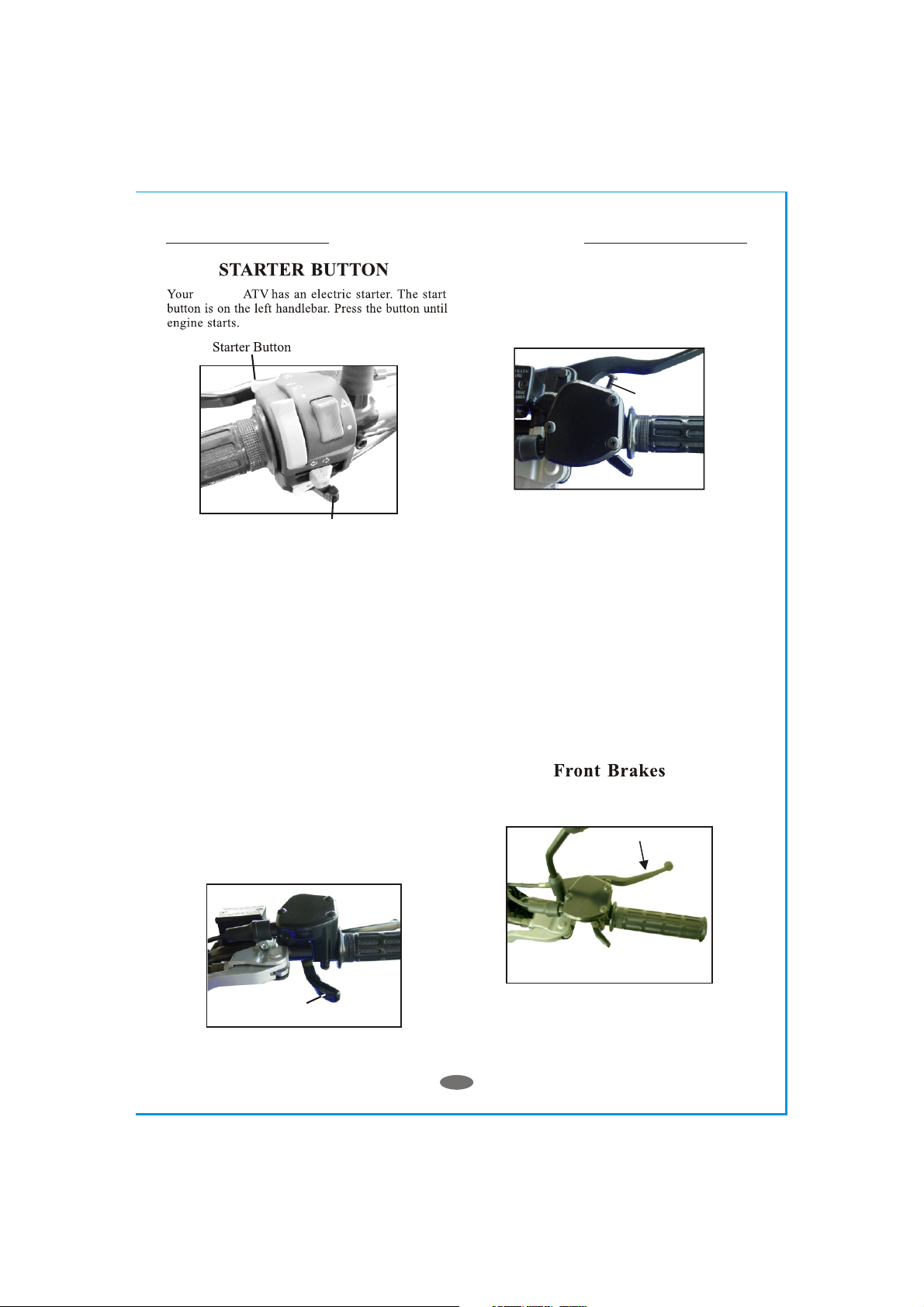
BRAKE CONTROLS
This vehicle is equipped with dual front
hydraulic disc brakes and a rear hydraulic
disc brake.
THROTTLE LEVER
The throttle lever is located on the right-hand
handle bar below the grip. To operate the
throttle lever, place your right thumb on the
lever and press forward to increase your speed.
To decrease your speed, reduce your pressure
on the lever and the spring tension will
automatically reduce your speed.
Throttle
The front brakes are controlled by the long
brake lever on the right-handle bar.
03
Page 6
CONTROL FEATURES
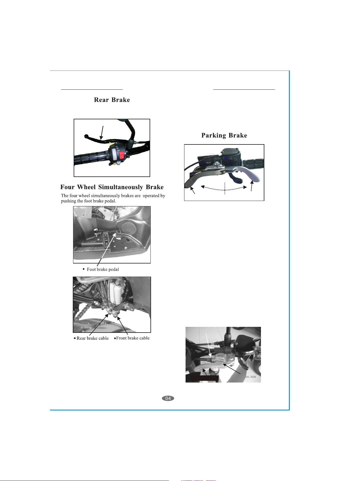
Parking Brake Adjustmemt
Parking Off
the adjustable nut
The rear brake is controlled by the long brake
lever on the left-handle bar.
pressure to your front brakes so that the
wheels lock up, stop turning, and causing a
loss of steering control. if the front wheels lock
up, and stop turning, lightly reduce the
pressure on the front brake lever until they
unlock and start to turn.
The rear brake is the primary stopping brake
on your vehicle. Using the rear brake to stop
your vehicle will prevent steering control loss.
Use your front and rear brakes in combination
(or use the four wheel simultaneously barke)
to control your speed while descending a
grade. Use caution not to apply too much
Parking Off
The parking brake is shown on the picture.
The position of parking Off is on the left
side. Turn parking brake to right side is
parking On.
This should be engaged as a parking brake
whenever the vehicle is not in operation.
Parking On
Parking Brake Adjustmemt
As you found out the parking brake which
has been decreased its brake ability.
You must adjus the parking brake.
1. Turn the parking brake to"Parking Off"
position. then screw the adjustable nut
to original position.
2. Lossen"Parking Brake Adjustable Nut"
near the rear brake caliper.Use your hand
to screw "Parking Brake Adjustable Bolt"
by clockwise to the end. Then back to a
quarter turn, tighen the nut to complete
the parking brake adjustable.
the adjustable nut
Parking Off
the parking brake
Page 7
3. Also,as you found out the parking brake
Parking Brake Adjustable Bolt
Parking Brake Adjustable Nut
ability which is a bit insufficient, you can
screw the adjustable nut of parking brake.
The fuel tank fill cap is located on top of the
unit just ahead of the seat. The cap contains a
vent to prevent a vacuum from forming in the
tank as fuel is used. The vent tube must be
attached to the cap and inserted in the vent
tube holder hole while operating the unit. The
fuel cap vent and vent tube must be clean and
clear of obstructions for the unit to operate
normally. You can check the vent and vent
tube by blowing air through the tube. If you can
not blow through the vent tube and cap you
must clean the vent and tube or replace them.
CONTROL FEATURES
Parking Brake Adjustable Bolt
Parking Brake Adjustable Nut
FUEL SYSTEM
Fuel Tank
cause damage to the cap or seal.
The fuel tank capacity is 12 liters, 3.17 gal,
including a reserve of 2.5 liters, 0.66 gal.
Use unleaded automobile gasoline with an
octane level of 91 or higher.
YourATV is equipped with a fuel gage located
in the instrument cluster between the handlebars.
NEVER REFUEL YOUR ATV when the
engine is HOT. Wait 30 minutes after turning
off the unit before refueling. Spilling fuel on a
HOT engine could cause a fire. Wipe up any
fuel spills before re-starting.
Fuel Valve
The unit is equipped with a three way fuel
valve located on the left side of the unit just
below the seat.
The valve has three settings; "ON", "RES"
and "PRI".
PRI
ON
RES
Fuel Tank Cap
& Vent Line
Every time you refuel your unit, check the
rubber seal inside the cap for cuts, tears and
dirt. Clean or replace the seal if it becomes
worn or torn. The seal must be in good
condition to insure a proper seal of the cap to
the tank to prevent fuel spills. DO NOT allow
dirt or other debris to enter the tank when
refueling.
Replace the cap if damaged or if it will not seal
to the tank.
Tighten the cap snugly, being careful not to
over tighten. Over tightening the cap can
Place the valve in the "ON" for normal operation
of the unit.This allows fuel to flow to the
carburetor for normal operating. The "RES"
position allows fuel to flow from the small
reserve in the tank to allow the unit to be
taken to a refueling location. When you have
to switch to the "RES" position you must refuel
the unit as soon as possible.
When the fuel valve set on the "ON" or "RES"
position, the unit is equipped with a vacuum
controlled fuel valve. The fuel supply is autom
Fuel Line
Vacumn Control
Line
Page 8
CONTROL FEATURES
atically shut off when the engine is stopped.
The fuel will automatically begin to flow when
the engine is turned over.
To test the fuel valve remove the fuel line from
the carburetor and place the end in a container
to catch the fuel. Insure that your tank has fuel
and press the starter button. Fuel should flow
Into the container from the fuel line.
When the fuel valve set on the "PRI" Position,
the unit is not equipped with a vacuum
controlled fuel valve. The fuel will flow to the
carburetor directly.
The purposes of "PRI" include two functions.
One is let fuel flow out when repairing ATV,
another reason is if all above operations fail,
the user can turn the fuel valve to "PRI" position
in order to let fuel flow into the carburetor
favorably.
ALWAYS CHECK YOUR Fuel level before
you start riding your ATV. Remember:
You can drive further in one hour on your ATV
than you can walk in one day.
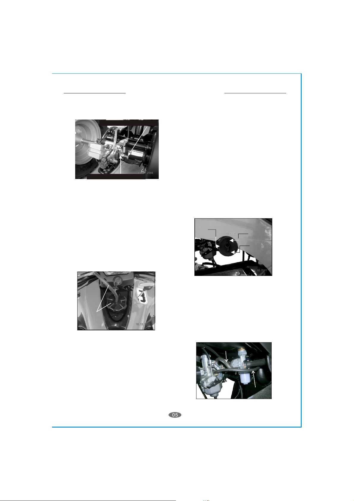
Inline Fuel Filter
Your ATV is equipped with an inline fuel filter
to prevent dirt and debris from entering the
carburetor and engine.
Check the filter for dirt or damage before each
ride and at each refueling. Replace the filter if
dirty or damaged.
DO NOT operate the unit with out a fuel filter.
Doing so can cause damage to the carburetor
and engine.
Inline Fuel Filter
Remove the filter from the fuel line by holding
the line and pulling the filter. Install the new
filter by inserting the filter into the fuel line and
returning the clamps to the original position.
Turn the fuel valve to the "PRI" position and
check for leaks. Inspect the fuel lines for cuts,
abrasions and deterioration. Replace fuel lines
as needed. Return the fuel valve to the "ON"
position for normal operations.
DO NOT start or operate the engine if the fuel
filter or lines are leaking. Leaking fuel can
cause a fire.
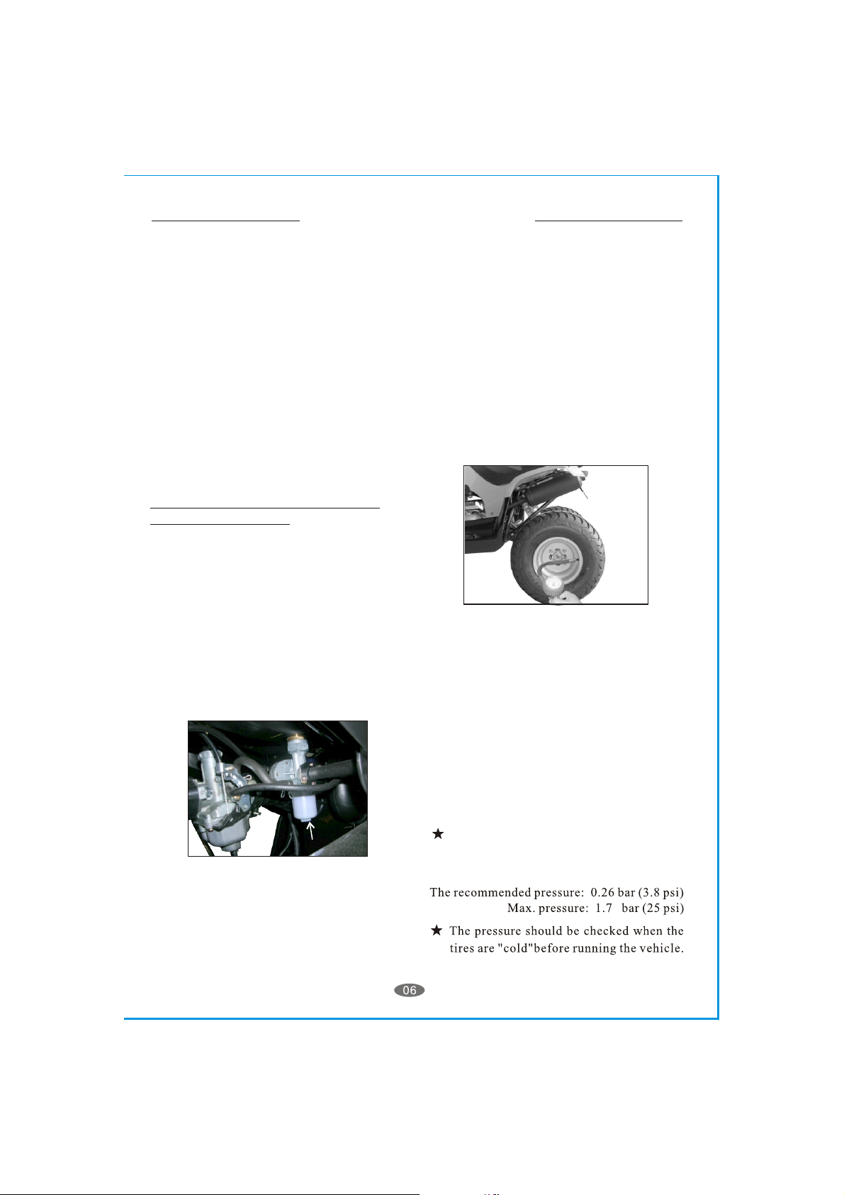
TIRES AND WHEELS
Tire & Wheel inspection
It is important to inspect your tires and wheels
for damage and wear before each riding
session. Inspect each tire for cuts, tears and
punctures. Inspect the wheel rim for dents and
separation of the wheel from the tire bead.
Replace any tire or wheel found to be
damaged.
Operating your ATV with damaged tires or
wheels is dangerous. Damaged tires or wheels
can result in a sudden loss of tire pressure and
control which could result in injuries.
Check your tire pressure before each riding
session and at each refueling operation.
Always check the pressure when the tires are
cool. Use the tire pressure gauge that came
with your ATV to check the tire pressure.
Wheel Nuts torque 24-30 N/m (18-22 1b/ft)
The filter should be replaced every 600 hours
of operation and at the start of each season.
To replace the filter, first turn the fuel valve to
the "ON" or "RES" position. Then carefully
compress the wire clamp rings until the clamp
is free of the fuel line. Slide each clamp away
from the filter about 3/4".
Tire Pressure
Page 9

FUEL INDICATOR METER
2
5
3
4
6
7
5
3
9
8
1
REVERSE INDICATOR LAMP
Your ATV is equipped with a fully automatic
C.V.T. transmission and has forward and
reverse gearing. A transmission shifting shaft
is located on the right hand side of your vehicle.
The shifter has three positions "F" Forward, "N"
Neutral and "R" Reverse.
The instrument panel has three lights that
correspond to the transmission shifter shaft
position.
The transmission must be placed in the "N"
(neutral - Green indicator Lamp) to start the
engine.
Slowly move the shifting lever to the desired
gear pausing slightly at the neutral position.
Once you have the gear selected increase the
throttle slowly until the transmission becomes
fully engaged and the vehicle starts moving in
the desired direction.
When shifting gears it is important that you
bring the vehicle to a complete stop with the
rear brake fully engaged and the enqine at idle.
If you attempt to shift the transmission with the
engine running above the idle speed the
engine will automatically shut down to protect
the transmission.
If this should happen you will need to turn off
the ignition switch to reset the safety lock out
before attempting to restart the enqine.
Page 10

SPEEDOMETER & ODOMETER
1
2
Page 11

SPECIFICATIONS
Engine
Typ e
Displacement
Bo re / Stro ke
Compression
Power
Transmission
Typ e
Chassis
Overall Length
Overall Width
Overall High
Wheel Base
Dry Weight
Suspension
Front
Rear
Brakes
Front
Rear
Tires
Front
Rear
Tire Pressure
Wheels
Bolt Pattern
Carburetor
Make/Size
Main Jat
Pilot Jet
Air Mixture Adjustment
Idle Speed
Sprockets
Frnot
Rear
Chain
Battery
Fluids
Fuel
Engine Oil
Transmission
Spark Plug
NGK
Carrying Capacity
Rack Capacity
Tow in g Ca pa ci ty
Maximum Rider Weight
Minimum Rider Age
Typ e
Volume
Typ e
Volume
Typ e
Volume
Electrode Gap
Front
Rear
Trailer Weight
Tongue Weight
4 Stroke Single Cylinder Liquid cooled
249 cc
71mm * 63mm
10.8:1
19ps @ 6500rpm
Automatic (CVT V-belt + Reverse)
1830mm / 72.0"
1040mm / 40.9"
1150mm / 45.3"
1190mm / 46.9"
215kg / 474 lbs
Dual A-arm/ Adjustable Shocks @ 2.95" travel
Swing Arm/ Adjustable Shock @ 4.72" travel
Hydraulic Disc*2
Hydraulic Disc
21*7-10
22*10-10
3.8psi / 0.265kg/cm
4 x 110mm
Kei-Hin with Manual choke
1.1mm
0.35mm
Back out 1 - 2 turns
Idle 1600 - 1800rpm
15 teeth
38 teeth
#520*90 O-Ring
12V-10AH-GTX12-BS
Unleaded Gasoline 89 octane
12 li te rs / 3. 17 g a l
SAE 10W-30
1.4 liters / 1.4gt (1.2 liters / 1.2gt for change)
SA E 85W-1 40 e ight g ear Oi l
750cc / 25.4oz (650cc / 22oz for change)
NGK-CR8E
0.6-0.7mm / 0.023"-0.027"
--/--
16kg / 301b
150kg / 3001bs
50kg / 110lbs
150kg / 330lb
16 years
2
/ 0.26bar
2
/
4
NO
OPTION
ET300ET250
4 Stroke Single Cylinder Liquid cooled
287.2 cc
75mm * 65mm
10.0:1
20ps @ 6500rpm
Automatic (CVT V-belt + Reverse)
1830mm / 72.0"
1040mm / 40.9"
1150mm / 45.3"
1190mm / 46.9"
217kg / 478 lbs
Dual A-arm/ Adjustable Shocks @ 2.95" travel
Swing Arm/ Adjustable Shock @ 4.72" travel
Hydraulic Disc*2
Hydraulic Disc
21*7-10
22*10-10
3.8psi / 0.265kg/cm
4 x 110mm
Kei-Hin with Manual choke
1.08mm
0.35mm
Back out 1 - 2 turns
Idle 1600
15 teeth
38 teeth
#520*90 O-Ring
12V-10AH-GTX12-BS
Unleaded Gasoline 89 octane
12 li te rs / 3. 17 g a l
SAE 10W-30
1.4 liters / 1.4gt (1.2 liters / 1.2gt for change)
SAE 85W-140 eight gear Oil
750cc / 25.4oz (650cc / 22oz for change)
NGK-CR8E
0.6-0.7mm / 0.023"-0.027"
--/--
16kg / 301b
150kg / 3001bs
50kg / 110lbs
150kg / 330lb
16 years
2
/
4
100rpm
NO
OPTION
2
/ 0.26bar
Page 12

[The are equipped with a
ET250
This choke is operated by the lever at the bottom
When first starting the engine,(cold start), place
As the engine warms return the lever to
manually operated carburetor choke system.
of the left hand control switch.
the lever in the full left position, (Choke closed or on)
the full right position. (Choke open or off).]
BREAK-IN YOUR NEW DAELIM ATV
DAELIM
Page 13

Page 14

DAELIM
12
Page 15

THROTTLE LEVER
Throttle
The throttle lever is located beside the righthandlebar grip and is operated by using the righthand thumb. The lever is spring loaded and will
return to the idle position when you remove your
thumb from the lever. To accelerate the unit,
simply press the lever forward to open the throttle
slide in the carburetor. To slow the unit, reduce the
pressure on the lever or remove your thumb and
the throttle will return to the idle position
automatically.
Adjusting the throttle cable
Adjuster Nut
The cable should be adjusted to allow for " free
travel before the throttle engages the carburetor
throttle slide. Slide the adjuster cover down the
cable to uncover the adjuster assembly. To adjust
the cable's free travel, loosen the locking nut of
the cable adjuster, and turn the adjuster nut until
there is " free travel in the lever. Tighten the
locking nut to secure the adjusting nut. Slide the
1
/
8
cover back over the adjuster assembly.
The speed of the unit can be adjusted by
adjusting the throttle stop screw to limit throttle
travel. Loosen the throttle stop screw locking nut
Locking Nut
1
/
8
Throttle Stop
Adjustment Boit
and turn the throttle stop screw clockwise to
reduce the throttle travel thus reducing the
maximum speed of the unit. Turning the stop
screw counter clockwise will increase the throttle
travel thus increasing the maximum speed of the
unit. Tighten the stop screw locking nut when the
desired throttle travel has been established.
SPARK PLUG
Replace spark plug at the beginning of each
season with a replacement plug NGK-CR8E.
Disconnect spark plug wire.
Clean dirt from around spark plug base with
brush or compressed air.
Remove spark plug with spark plug wrench.
Set the spark plug gap on the new plug to
0.023"
Install the new plug screwing it in finger tight
and then use the plug wrench to screw the
plug in another turn.
Inspect the spark plug wire for cuts, nicks or
other damage. Replace as needed.
1
/
2
Page 16

BRAKING SYSTEMS
Your ATV unit is equipped with dual front
hydraulic disc brakes and a rear hydraulic
disc brake. The front brakes (right) and rear
brake (left) are applied by squeezing the brake
lever on the right & left handle-bar , while the
four wheel simultaneous brakes are applied
by pressing the brake pedal on the right-footrest.
Proper maintenance of the brake system is a
necessary part of safe operation of your unit. The
brake systems should be inspected and tested
before each riding session.
The Brake Cables Inspection
Visually inspect the brake cables for any signs of
wear. Inspect the cables for frays and kinks that
Inhibit the free movement of the cable. Replace
frayed or kinked cable before operating your unit.
inspect the cables for rust or corrosion. Replace
any brake cable that show signs of corrosion as
this could cause a reduction in cable strength that
can lead to the cable breaking.
Test the brakes by applying pressure to the
brake lever and trying to push the unit forward. If
the wheel rotates while the brakes are applied,
adjust the brake cable until the wheels no longer
rotate.
(See Brake Adjustment)
The Brake Cables Adjustment
Adjust the brake cable so that the lever has zero
free play and a minimum clearance of "
between the lever and the handle grip when the
brake is fully applied. Adjust the cable by using
the adjustment wheel where the cable attaches
Adjusting Ring
The front
brakes
1
/
to the lever assembly. After obtaining the correct
adjustment, insure that the locking nut is
tightened securely against the adjusting wheel to
prevent the adjustment wheel from turning due
to vibration. Keep your brake cables lubricated
with a high quality cable lubricant to prevent rust
and corrosion. The cables should be lubricated
every 60 days or more often if operated in a
dusty or wet environment.
Replacement of the brake cables should ONLY
be preformed by a qualified mechanic.
The Brake Hoses Inspection
Visually inspect the brake hose for any signs of
wear or leaks. Check the fluid level in the fluid
reservoir by checking the position of cup behind
the right-footrest.
The fluid level should fill at least of the cup
when the unit is setting on a level surface.
Test the brakes by applying pressure to the brake
2
lever and trying to push the unit forward. If the
wheel rotates while the brakes are applied, check
The front
brakes
3
4
/
Locking Nut
Adjusting Ring
The rear
brake
Hose
The rear
brake
Page 17

Bleecler Valve
your fluid level and brake pads. If the brake lever
Bleecler Valve
Bleecler Valve
Cover
feels spongy or does not stop when squeezed,
you may have air in the lines. All air must be
purged from the brake lines for the disc brake to
operate properly. (See purging brake lines).
After riding your unit, be sure to clean any build up
of mud, sand and dirt from the brake rotor skid
plate. This will protect the rotor disc from rust and
corrosion.
Purging Brake Lines
To Fill The Reservoir
Remove the reservoir cover.
Fill the reservoir to 1/8" from top with Dot-3
SAE-J 1703 grade brake fluid.
Caution: DO NOT
Allow dirt to fall into the
reservoir
Refold the cover gasket as shown in picture and
replace cover.
Fill to 1/8"
from top
Bleecler Valve
Bleecler Valve
THE FRONT CALIPER
THE REAR CALIPER
For the hydraulic brake system to operate safely,
the brake system must be purged of air in the lines
and reservoir.
To bleed the air will require two people to perform
the following procedure.
1. Place a drain pan under the brake caliper
to catch the fluid.
2. Open the bleeder valve turn counter
clockwise.
3. Squeeze the brake lever to expel air from
1
/
2
the system.
4. While holding the brake lever, close the
bleeder valve.
5. Repeat steps 2 through 4 until the brake
fluid coming from the bleeder valve is a
solid stream without any air, then close the
valve and replace rubber protection cap.
6. Test the brake system by squeezing the
lever, the lever should feel firm and stop
without fading.
Page 18

DRIVE CHAIN
Air Filter Box
10-20mm
0.39"-0.79"
The drive chain will stretch with use and will
require periodic adjustments. To check the chain
tension, remove the chain guard and measure the
slack.
The amount of slack in the chain should not
exceed 10-20mm or 0.39"-0.79".
Inspect the drive and axle sprockets for worn,
damaged or broken teeth. Replace as needed.
Inspect the chain links for damaged, worn or loose
rivets. Repair or replace as needed.
Chain Slack Adjustment
Axle Locking Bolts
Loosen the axle position lock bolt slightly and turn
the chain adjuster nut to take up the excess slack
in the chain. Once the chain has been adjusted to
the proper tension retighten the axle position
locking bolt.
AIR FILTER
Air Filter Maintenance
To maintain the highest performance from your
engine and to reduce excessive wear that could
cause engine failure the engine requires a
continuous flow of clean air. Air is taken into the
engine through an air filter to clean the air prior
to mixing it with fuel in the carburetor.
During normal operation the filter accumulates
dirt from the air and will need to be cleaned to
maintain the proper air flow. The filter should
be cleaned every 30 days, more often if you
ride in a dusty or dirty environment and the
element should be replaced every year.
The air filter box is located under the seat toward
the front of the unit.
To Clean The Filter
Remove the cover of the air filter box.
Remove the filter element from the air box.
Chain Adjustment
The chain should be kept well lubricated to
prevent excess wear and premature failure. We
recommend that you lubricate the chain every 15
hours of operation, or more frequently if needed,
with a high quality chain lubricant.
Wash the element in a non-flammable solvent
such as air-filter cleaner from your local auto
parts dealer.
1. Dry the element completely before continuing.
2. Soak the element in clean engine oil until
completely saturated.
3. Squeeze out the excess oil until the element
does not drip any oil.
4. Allow the element to dry then reinstall the
element and cover.
Page 19

ENGINE WARTER COOLER
The engine coolant is cooled by an external
radiator located at the front of the unit. It is
important that the radiator fins be kept free of
dirt build up to prevent the engine from over
heating which can cause sever damage to the
engine. Remove any build up of dirt or mud from
the radiator fins with a pressurized spray of water.
Maintaining the coolant will allow the cooling
system to work properly and prevent freezing,
overheating,and corrosion.
PLEASE PAY SPECIAL ATTENTION that using
poor quality coolant may shorten the service life
of the radiator.
Concentration:50%.(Use distilled water when
mixing coolant)
Radiator capacity: Main radiator:800c.c.
Coolant should be changed once a year normally.
Reserved tank:350c.c.
Removing the radiator cap while the engine is
hot can cause the coolant to spray out,seriously
scalding you.Always let the engine and radiator
cool down before removing the radiator cap.
Checking LeverCoolant
Main radiator cap
Reserved tank
1.Stops ATV in the level place.
2.Remove the front cover.
3.Check reserved tank from viewing window
to see if coolant level is between the upper
limit and lower limit mark.
4.Add coolant up to upper mark if coolant is
close to the lower mark.
WARNING: The radiator coolant is under pressure
when hot. NEVER REMOVE the radiator cap until
the unit has cooled for at least 1 hour or server
injury or burns may result!
Reserved tank cap
Upper
Lower
Replenishment Of Coolant
1.Park the vehicle on level ground.
2.Remove the front cover.
a.Open reserved tank cap, refill coolant
until reaches the upper limit.
b.To avoid radiator getting rusty, do not use
coolant other than those recommended.
Replenishment OfAnti-freeze
Please refer to table showing what percentage
of anti-freeze should be used under different
temperatures if the vehicle is to be operated in
the low temperature areas.(below 0 c)
o
A reference table for anti-freeze concentration
percentage under differert temperatures
1.Radiator anti-freeze specification for this ATV
is H68.
2.Proper anti-freeze percentages for different
frozen temperatures are as follows:
3.If the specified anti-freeze is unavaiable,use
an equivalent with the same high quality.
4.Increase radiator maintenance intervals
when the weather is extremely cold.
Anti-freeze percentage
20%
30%
40%
50%
Freezing temperature
-8
-15
-24
-36
50% CONCENTRATION is used for all ATV
before delivery to ensure the effectiveness
of anti-freeze.
Check Cooling System For Leaks
If low coolant levels occur often or if coolant is
seen under unit after being parked it may indicate
a leak in your coolant system.
Inspect radiator and piping for leaks and damage.
Replace or repair any leaking radiator and piping
before starting the engine.
Page 20

ENGINE OIL
•••••
Checking Engine Oil Level
Engine Oil Dip Stick
& And F ill Tube
Engine Oil Drain
Lower
Upper
Your ATV uses automotive type engine oil to
lubricate the engine. The engine oil dip stick is
located on the right hand side of your engine
below the transmission shifting lever.
To check your oil level, remove the dip stick by
turning the thumb hold counter clockwise until
the stick has been completely disengaged from
the threads. Pull the dip stick out of the
crankcase and check the level of the oil as
indicated on the dip stick. The engine oil is full
when the oil reaches the level on the stick as
indicated in the photo above.
Always check your engine oil level with the
engine off and cold. Removing the dip stick
with the engine running could cause hot oil to
splash from the crankcase causing severe
burns.
Checking your engine oil while the engine is
hot can give you a false reading; always check
the oil level with a cold engine.
Your engine requires SAE 10W-30 engine oil and
the crankcase capacity is 1.2 Liters / 1.2 quart.
The engine oil should be changed before the
start of each riding season or every 1000KM
of operation. When riding where conditions are
dusty or humidity is high the engine oil should
be change more frequently.
•••••
••••••• •••••••••••
2. Remove the crankcase drain plug located
on the bottom of the crankcase on the underside
of the unit.
3. Remove the engine oil dipstick located on the right
hand side of the engine below the shifter shaft.
4. Allow the oil to drain completely (15-30 min).
5. Reinstall the drain plug and tighten.
Torque to 7-101bf-ft
6. F ill the c rankcase with o f SAE 10W-30 e ngine o il
through the dip dipstick hole.1.2 Liters/1.2 quart.
7. Reinstall the engine oil dipstick and finger
tighten.
8. Dispose of used oil at a proper recycling
station as required by law
TRANSMISSION OIL
Your ATV uses SAE 85W-140 gear oil to
lubricate the drive and transmission gears.
Your gear oil should be checked before each
riding session. The gear oil should be changed
before each riding 1 year or every 5000KM
operation.
Changing Transmission Oil
Transmission
Oil Filler Hole
Changing Engine Oil
1. Place an oil catch pan under the unit directly
below the engine crankcase.
1. P lace a no il c atch p an u nder the u nit d irectly
below the transmission box.
Page 21

•••••
Seat Latch
Transmission
Oil Drain
••••••• •••••••••••
2.Remove the tr ansmission b ox d rain p lug
located on the bottom of the transmission
box on the underside of the unit.
3. R. emove t he t ransmission box f ill hole plug locate
on top of the transmission box on the right hand
side of the engine.
4. A llow the o il to d rain completely (15-30 min).
5. Reinstall the d rain p lug a nd tighten.
Torque to 7-101bf-ft.
6. Fill t he t ransmission box with of SAE 85W-140
gear oil 250cc engine = 650cc /22oz.
7. Reinstall t he f ill hole plug and t orque t o 2-31bf-ft.
8. Dispose of used oil at a proper recycling
station as required by law.
ELECTRICAL BATTERY
Battery GTX12-BS
When reinstalling the battery, be sure to connect
the red cable to the positive (+) terminal and the
black cable to the negative (-) terminal.
The battery should be replaced every three years
or when it no longer holds a charge.
Do not expose the battery, for extended periods of
time, to freezing temperatures. If the battery has
been frozen it will need to be replaced. There are
inline fuses on the positive lead of the battery to
protect the wiring system from over loads. If your
starter motor will not turn over and the battery is
fully charged, check the inline fuse on the unit.
The unit's battery is located under the seat and
supplies electrical power to the unit. The battery
is a 12 volt jell acid type that contains no liquid
electrolyte. The battery should be removed from
the vehicle when stored for extended periods
and charged before being replaced in the unit.
Use a trickle charger set at 12 volts to recharge
the battery to full charge before replacing it in
the unit.
Amperage
Rating
15A
10A
30A
15A
Green
Color
Blue
Red
Blue
Series Items
Head Lamp
Fan Motor
Battery
Position Lamp
Stop&Tail Lamp
License Lamp
Illumi Lamp
Winke Lamp
For anothers series items of electrical units,
please refer to the fuse as shown in list.
Page 22

I, L
I
R
Page 23

Page 24

NOTATION
 Loading...