


Cybex 525AT Arc Trainer®
Service Manual
Cardiovascular Systems
Part Number 525AT-901 -
www.cybexintl.com
Cybex Service Manual
Table of Contents
FCC Compliance Information . . . . . |
. |
3 |
Service |
|
|
|
|
|
|
|
Console Display . . . . . . . . . . . . . . . . . . . . . . |
17 |
|||
Safety |
|
|
User Controls . . . . . . . . . . . . . . . . . . . . . . . . |
18 |
|||
Ground and Voltage Information . . . . |
. |
4 |
User Control Symbols Used . . . . |
. |
. |
19 |
|
Setup . . . . . . . . . . . . . |
. |
. |
20 |
||||
Important Safety Instructions . . . . . . |
|
. 4 |
|||||
|
Service Diagnostics . . . . . . . . |
. |
. 22 |
||||
Warning and Caution Decals . . . . . . |
|
. 6 |
|||||
|
Error Codes . . . . . . . . . . . |
. |
. 23 |
||||
|
|
|
|||||
Maintenance |
|
|
Linkage Rod . . . . . . . . . . |
. |
. |
25 |
|
|
|
Arm Handle Linkage . . . . . . . |
. |
. |
26 |
||
Warnings . . . . . . . . . . . . . |
. |
9 |
Foot Plate Assembly . . . . . . . |
. |
. |
26 |
|
Preventive Maintenance Activities . . . . |
|
10 |
Front Foot Plate Arm . . . . . . . |
. |
. |
27 |
|
Cleaning Unit . . . . . . . . . . . . |
|
10 |
Rear Foot Plate Arm . . . . . . . |
. |
. |
27 |
|
Remove Access Cover . . . . . . . . |
|
11 |
Arm Handle . . . . . . . . . . . |
. |
. 30 |
||
Drive Belts . . . . . . . . . . . . . |
|
12 |
Crank Covers . . . . . . . . . . . . . . . . . . . . |
. . |
. . |
34 |
|
Attach Access Cover . . . . . . . . . |
|
12 |
Shrouds . . . . . . . . . . . . |
. |
. |
34 |
|
E3 View Monitor . . . . . . . . . . |
. 13 |
Control Board . . . . . . . . . . |
. |
. 35 |
|||
Recommended Service Schedule . . . . |
|
13 |
Crank Arms . . . . . . . . . . . |
. |
. 35 |
||
|
|
|
Crank Shaft Assembly . . . . . . . |
. |
. 35 |
||
Customer Service |
|
|
Counterweights . . . . . . . . . |
. |
. |
36 |
|
Product Registration . . . . . . . . . |
|
15 |
Lower Pivot Assembly . . . . . . . |
. |
. 36 |
||
Contacting Service . . . . . . . . . |
. 15 |
Incline Motor . . . . . . . . . . |
. |
. |
41 |
||
Ordering Parts . . . . . . . . . . . |
. 15 |
Accessory Tray . . . . . . . . . |
. |
. |
48 |
||
Return Material Authorization (RMA) . . . |
|
16 |
Contact Heart Rate Grips . . . . . |
. |
. |
52 |
|
Damaged Parts . . . . . . . . . . . |
|
16 |
LED Display Board . . . . . . . . |
. |
. 54 |
||
|
|
|
E3 View Monitor . . . . . . . . . |
. |
. 58 |
||
|
|
|
MCC Board . . . . . . . . . . . |
. |
. 64 |
||
|
|
|
Update Software . . . . . . . . . |
. |
. 69 |
||
|
|
|
Appendix – Schematic |
|
|
|
|
|
|
|
Schematic 525AT . . . . . . . . |
. |
. |
73 |
|
Cybex® and the Cybex logo are registered trademarks of Cybex International, Inc. Polar® is a registered trademark of Polar Electro Inc. iPOD® is registered trademark of Apple.
DISCLAIMER: Cybex International, Inc., makes no representations or warranties regarding the contents of this manual. We reserve the right to revise this document at any time or to make changes to the product described within it without notice or obligation to notify any person of such revisions or changes.
© Copyright 2013, Cybex International, Inc. All rights reserved. Printed in the United States of America.
10 Trotter Drive Medway, MA 02053 • 508-533-4300 • FAX 508-533-5183 • www.cybexintl.com • 525AT-901 - • July 2013
2

Cybex Service Manual
FCC Compliance Information
Changes or modifications to this unit not expressly approved by the party responsible for compliance could void the user’s authority to operate the equipment!
This equipment has been tested and found to comply with the limits for a Class B digital device, pursuant to part 15 of the FCC Rules. These limits are designed to provide reasonable protection against harmful interference in a residential installation. This equipment generates, uses and can radiate radio frequency energy and, if not installed and used in accordance with the instructions, may cause harmful interference to radio communications. However, there is no guarantee that interference will not occur in a particular installation. If this equipment does cause harmful interference to radio
or television reception, which can be determined by turning the equipment off and on, the user is encouraged to try to correct the interference by one or more of the following measures:
•Reorient or relocate the receiving antenna.
•Increase the separation between the equipment and receiver.
•Connect the equipment into an outlet on a circuit different from that to which the receiver is connected.
•Consult the dealer or an experienced radio/TV technician for help.
3
Cybex Service Manual
Safety
Read all instructions and warnings before using.
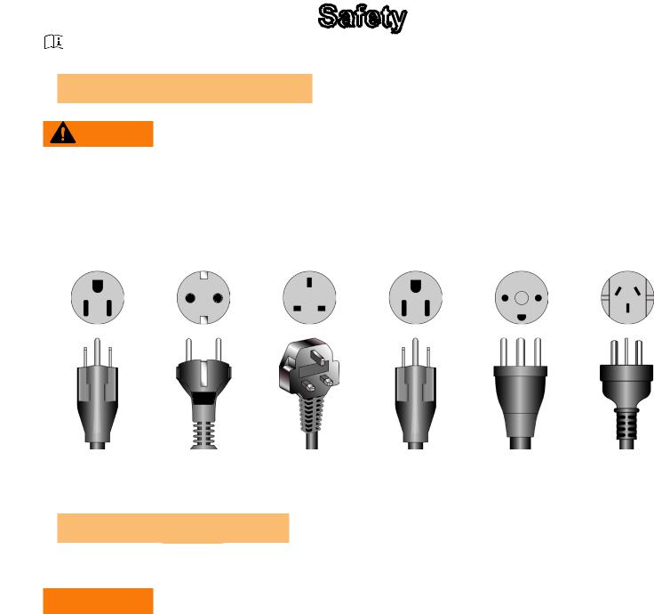
and Voltage Information
WARNING: Shock and electrocution hazard
•Connect unit to a grounded outlet.
•Do not use voltage adapter or extension cord.
Cybex is not responsible for injuries or damages as a result of cord or plug modification.
•Verify voltage requirements of unit match local voltage requirements.
•Verify unit outlet is the same configuration as the plug.
|
|
|
|
|
|
|
|
|
|
|
|
115 VAC |
Euro Plug |
UK 230 VAC |
Japanese |
Danish |
Australia |
NEMA 5-15 |
CEE 7/7 |
BS 1363 |
JIS 8303 |
107-2-D1 |
AS/NZS 3112 |
Important Safety Instructions
(Save These Instructions)
 WARNING: Shock and electrocution hazard
•Unplug unit and let sit 10 minutes before cleaning or performing maintenance
•Electrical charge can remain in unit after unplugging
•Keep water and liquids away from electrical parts
User Safety Precautions
•KEEP ALL CHILDREN 12 AND UNDER AWAY! Teenagers or disabled must be supervised.
•Obtain a medical exam before beginning any exercise program.
•Stop exercising if feeling faint, dizzy, or experiencing pain and consult your physician.
•Obtain instruction before using.
• Read and understand all warnings posted on the unit before using.
•Use the handrails for support and to maintain balance.
•Wait until foot plates come to a complete stop before dismounting.
4
Cybex Service Manual
•Keep foot plate surface clean and dry.
•DO NOT wear loose or dangling clothing while using.
•Keep all body parts and other items free and clear of moving parts.
•DO NOT use unit if user exceeds 400 lbs. (180 kg). This is the rated maximum user weight.
•Report any malfunctions, damage or repairs to the facility.
•Replace any warning labels if damaged, worn or illegible.
Facility Safety Precautions
It is the sole responsibility of the user/owner or facility operator to ensure that regular maintenance is performed.
•Enforce all user and safety precautions.
•Read and understand the Owner’s Manual completely before assembling, servicing or using unit.
•Verify all users are properly trained on using the equipment.
•Do not use unit outdoors.
•Verify that each unit is setup, leveled and operated on a solid level surface. Do not install equipment on an uneven surface.
•Verify there is enough room for safe access and operation of unit.
•Do not use the unit if: (1) the unit is plugged into an optional power adapter that has a damaged cord; (2) the unit is not working properly or (3) if the unit has been dropped or damaged. Seek service from a qualified technician.
•EQUIPMENT is not suitable for use in the presence of aerosol (spray), FLAMMABLE
ANAESTHETIC MIXTURE WITH AIR or WITH OXYGEN or NITROUS OXIDE.
•Perform regular maintenance checks on unit. Performance level can be maintained only if examined regularly. Pay close attention to all areas most susceptible to wear, including (but not limited to) cables, pulleys, belts and grips.
•Replace any warning labels if damaged, worn, or illegible.
•Immediately replace worn or damaged components. If unable to immediately replace worn or damaged components, then remove unit from service until repair is made.
•Do not attempt electrical or mechanical repairs. Seek qualified repair personnel when servicing. If you live in the USA, contact Cybex Customer Service at 888-462-9239. If you live outside the USA, contact Cybex Customer Service at 508-533-4300.
•Use only Cybex supplied components to maintain/repair unit.
•Keep a repair log of all maintenance activities.
•Disconnect the power cord before servicing unit.
•Do not use attachments unless recommended for the unit by Cybex.
•The unit may generate electromagnetic or other forms of interference, or it may be affected by interference from other equipment nearby. If this is suspected, take precautions by separating the equipment or otherwise shielding it to avoid such interference.
5
Cybex Service Manual
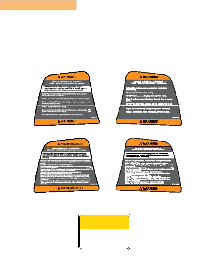
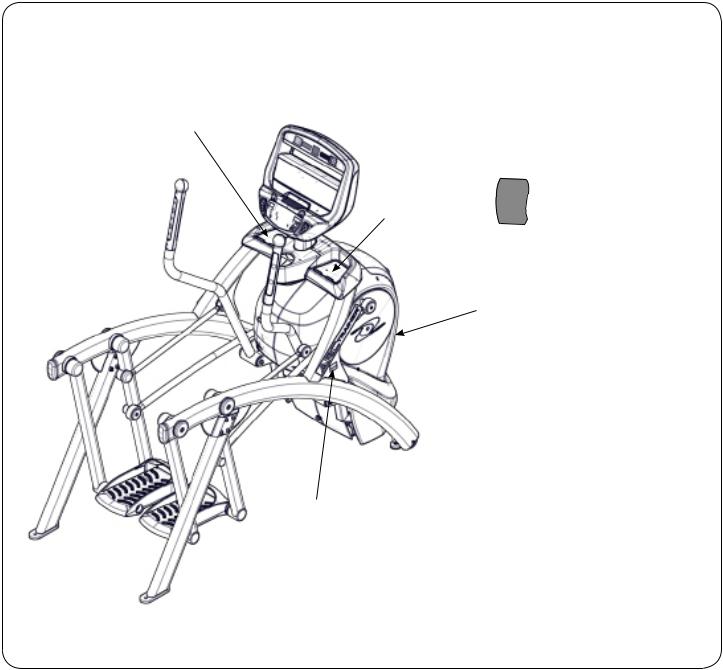
Warning and Caution Decals
To replace any worn or damaged decals do one of the following: Visit www.cybexintl.com to shop for parts online, fax orders to 508-533-5183 or contact Cybex Customer Service at 888-462-9239. If you are located outside of the USA, call 508-533-4300. For location or part number of labels, see the parts list and exploded-view diagram on the Cybex web site at www.cybexintl.com.
Warning decals indicate a potentially hazardous situation which, if not avoided, could result in death or serious injury.
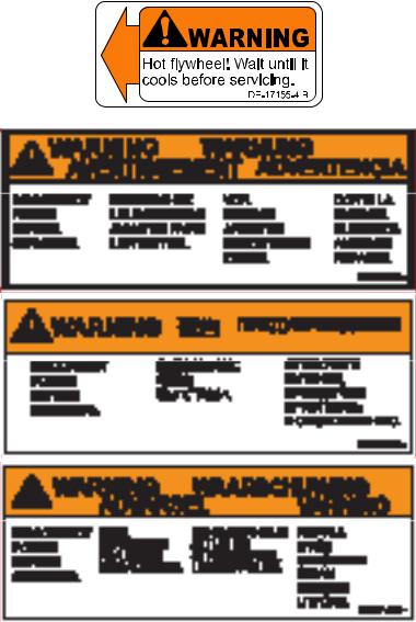
Carefully
 CAUTION
Moving parts. Keep hands away when in use.
DE-17219-4 B
MASTER
6
Cybex Service Manual
7
Cybex Service Manual
1
2
4
5
3
1 |
770A-331-4 |
Label, Warning, Access tray, Left |
1 |
770A-331-E |
Label, Warning, Access tray, Left, Canadian |
2 |
770A-332-4 |
Label, Warning, Access tray, Right |
2 |
770A-332-E |
Label, Warning, Access tray, Right, Canadian |
3 |
DE-18362-4 |
Decal, Caution moving parts |
4 |
DE-18363-4 |
Label, Warning, Hot flywheel |
5 |
525AT-400 |
Label, Warning, Disconnect Power |
5 |
525AT-401 |
Label, Warning, Disconnect Power |
5 |
525AT-402 |
Label, Warning, Disconnect Power |
8
Cybex Service Manual
Maintenance
All preventive maintenance activities must be performed on a regular basis. Performing routine preventive maintenance actions can aid in providing safe, trouble-free operation of all Cybex equipment.
Cybex is not responsible for performing regular inspection and maintenance actions for your machines. Instruct all personnel in equipment inspection and maintenance actions and also in accident reporting/recording. Cybex representatives are available to answer any questions that you may have.
WARNING: For maintenance, service and repair
•Should only be performed by trained personnel
•Use only Cybex replacement parts
•Unplug unit before working on it
•Keep water and liquids away from electrical parts
Warnings
 Read all warnings in this chapter and in the Safety Section.
Observe the following warnings:
DANGER: Electrocution hazard
To avoid death or serious injury unplug unit when not in use or when performing maintenance
WARNING: Equipment hazard
To avoid serious injury or death replace worn or damaged components immediately and keep the equipment out of use until repair is completed
NOTICE: Repairs and Service
•All inspections and repairs must be performed by trained service personnel only
•Cybex requires that only Cybex replacement parts are used
9
Cybex Service Manual
Preventive Maintenance Activities
Perform regular preventive maintenance to ensure normal operation of unit. Keep a log of all maintenance actions to assist in staying current with all preventive maintenance activities.
Cybex is not responsible for performing regular inspection and maintenance actions for your unit. Instruct all personnel in equipment inspection and maintenance actions and also in accident reporting/ recording. Contact Cybex Customer Service at 888-462-9239 or 508-533-4300 for any preventive maintenance or service concerns.
Read and understand warnings listed in this chapter and in the Safety Section. Read and understand all instructions in this section.
During maintenance, disconnect the power cord from the power outlet.
For some maintenance activities it will be necessary to remove and replace the access cover.
Tool Required
Phillips screwdriver
Cleaning Unit
When cleaning your treadmill spray a mild cleaning agent, such as a water and dishsoap solution, on a clean cloth first and then wipe the treadmill with the damp cloth. Do not spray cleaning solution directly on the treadmill. Direct spraying could cause damage to the electronics and may void the warranty.
WARNING: Shock and electrocution hazard
•Unplug unit and let sit 10 minutes before cleaning or performing maintenance
•Electrical charge can remain in unit after unplugging
•Keep water and liquids away from electrical parts
After Each Use — Wipe up any liquid spills immediately. After each workout, use a cloth to wipe up any remaining perspiration from the handrails and painted surfaces.
Be careful not to spill or get excessive moisture between the edge of the display panel and the console, as this might create an electrical hazard or cause failure of the electronics.
As Needed — Vacuum any dust or dirt that might accumulate under or around the unit. Cleaning this area should be done as often as indicated in the Service Schedule.
Contact Heart Rate Grips — Contaminants, such as hand lotions, oils or body powder, may come off on the contact heart rate grips. These can reduce sensitivity and interfere with the heart rate signal.
It is recommended that the user have clean hands when using the contact heart rate. Clean the grips using a cloth dampened with a cleaning solution containing rubbing alcohol.
10
Cybex Service Manual
Remove Access Cover
1. Remove the two lower
lower  screws securing
 the access cover using a Phillips screwdriver.
1 |
1 |
2 |
3 |
3 |
|
Item |
Description |
1 |
|
Upper screws |
2 |
|
Access cover |
3 |
|
Lower Screws (2) |
2.Remove two upper screws securing the access cover using a Phillips screwdriver. Refer to the above diagram.
Remove the access cover.
WARNING: Burn hazard
Do not touch flywheel until cool
11
Cybex Service Manual
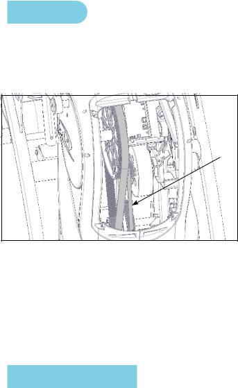
Drive Belts
There are two drive belts that may become loose, worn or cracked.
Unless the belts have been removed and not replaced properly, it is unlikely the belts will come loose or need to be re-tensioned.
|
Item |
Description |
1 |
|
Primary drive belt |
2 |
|
Secondary drive belt |
2
1
If a belt has cracks or appears worn, it must be replaced immediately by a qualified service technician.
Primary Belt – The wider of the two belts. It has grooves that keep it aligned on the large upper pulley.
Secondary Belt – The narrower of the two belts. It has grooves that keep it aligned on the flywheel’s drive pulley.
Attach Access Cover
Do not over tighten screws.
1.Replace and tighten the two upper screws removed in step 2 Remove Access Cover using a
Phillips screwdriver.
2.Replace and tighten the two lower screws removed in step 1 Remove Access Cover using a Phillips screwdriver.
3.Plug the power cord into a power outlet.
4.Test unit for proper operation.
12

Cybex Service Manual
E3 View Monitor
Cleaning
1.Unplug power cord from the wall socket.
2.Dust off the panel with a soft dry cloth as needed. The screen can be cleaned with computer screen wipes or other non-abrasive, moist, disposable wipes.
Storage or Long Non-Use Periods
When not using product for an extended period of time the product should be disconnected from the
Power Supply, TV/Cable Signal Feed, and any Peripheral Devices.
Pixels
Very small red, blue, white or green spots may be visible or may appear on the screen. This is a characteristic of liquid crystal display panels and is not a faulty condition. The liquid crystal panel is built with very high precision technology giving fine picture details. Occasionally, a few non-active pixels may appear on the screen as a fixed point. This does not affect the performance of monitor or merit a warranty claim.
Maintenance
•It is very important to have the unit regularly examined by a qualified technician to ensure the product is fit for use.
•If the unit malfunctions, please refer to a qualified technician for repair or replacement of defective parts immediately. Do not attempt to use the monitor until it has been inspected and repaired by a qualified technician.
•For inspection, installation and servicing, please consult qualified technician.
•Failure to use a manufacturer approved repair technician may void any warranty claims.
Recommended Service Schedule
All maintenance activities shall be performed by qualified personnel. Failure to do so could result in serious injury.
This is the minimum recommended service.
Determine distance
1.Verify foot plates are completely stopped.
2.Grasp handrail and step carefully onto foot plates. Begin striding.
3. Press and the hold the Display |
|
and DOWN |
|
keys for 3 seconds. A beep |
|
|
|||
|
|
|||
signifies the first screen of the Statistics menu. |
|
|
||
4. Press the UP and DOWN
 keys to scroll up and down in the statistics menu.
13
Cybex Service Manual
The Statistics menu includes: Miles/Km, Hours, Starts, and Error log.
5.The first menu item is Miles/Km.
6.Record Distance.
7.Navigate to menu item Hours.
8.Record Hours.
9.Navigate to menu item Error log.
10.Record Errors.
11.Exit Statistics menu by pressing the STOP key.
First 500 Miles (800 KM)
Follow this procedure to ensure the belts are tensioned properly and in good condition.
1.Unplug the unit from the power outlet.
2.Remove access cover. (See previous procedure Remove Access Cover)
3.Pull down and roll each belt to examine the condition. If a belt has cracks or appears worn, it must be replaced immediately by a qualified service technician.
4.Attach access cover. (See previous procedure Attach Access Cover).
5.Plug the power cord into a power outlet.
Every 5000 Miles (8000 KM)
Check drive belts for tension and wear. (See procedure First 500 Miles)
Move unit and vacuum underneath. Lift the rear of unit and roll it back from its present position. Vacuum underneath and return unit to normal position.
Clean inside unit.
1.Unplug the unit from the power outlet.
2.Remove access cover. (See previous procedure Remove Access Cover)
3.Clean the exposed components using a vacuum cleaner attachment or hand vacuum.
4.Remove dirt and debris from internal components.
5.Using a dry cloth, wipe all exposed areas.
6.Attach access cover. (See procedure Attach Access Cover).
7.Plug the power cord into a power outlet.
Every 20,000 Miles (32000 KM)
Contact qualified service technician to check elevation assembly, replace any worn parts and lubricate elevation bushings.
14
Cybex Service Manual
Customer Service
Product Registration
To register product do the following:
1.Visit www.cybexintl.com.
2.Locate Product Registration in the Support section.
3.Fill out form completely.
4.Click the Submit button to register product.
Contacting Service
Hours of phone service are Monday through Friday from 8:30 a.m. to 6:00 p.m. Eastern Standard Time.
For Cybex customers living in the USA, contact Cybex Customer Service at 888-462-9239.
For Cybex customers living outside the USA, contact Cybex Customer Service at 508-533-4300 or fax 508-533-5183. Email address internationaltechhelp@cybexintl.com
Find information on the web at www.cybexintl.com.
To contact us online go to www.cybexintl.com.
Ordering Parts
To order parts online go to www.cybexintl.com.
To speak with a customer service representative, call 888-462-9239 (for customers living within the USA) or 508-533-4300 (for customers outside the USA).
The following information located on the serial number decal will assist our Cybex representatives in serving you.
•Unit Serial Number, Product Name and Model Number
•Part Description and Part Number if you have it. All parts can be found on the web at www.cybexintl.com
•Shipping Address
•Contact Name
•Include a description of the problem.
In addition to your shipping address and contact name, your account number is helpful but not required. You may also fax orders to 508-533-5183.
15

Cybex Service Manual
Return Material Authorization (RMA)
The Return Material Authorization (RMA) system is used when returning material for placement, repair or credit. The system assures that returned materials are properly handled and analyzed. Follow the following procedures carefully.
Contact your authorized Cybex dealer on all warranty-related matters. Your local Cybex dealer will request a RMA from Cybex, if applicable. Under no circumstances will defective parts or equipment be accepted by Cybex without proper RMA and an Automated Return Service (ARS) label.
Please contact Cybex Customer Service for the return of any item that is defective.
Provide the technician with a detailed description of the problem you are having or the defect in the item you wish to return. Provide the model and serial number of your Cybex equipment.
At Cybex’s discretion, the technician may request that you return the problem part(s) to Cybex for evaluation and repair or replacement. The technician will assign you a RMA number and will send you an ARS label. The ARS label and the RMA numbers must be clearly displayed on the outside of the package that contains the item(s) to be returned. Include the description of the problem, the serial number of the equipment and the name and address of the owner in the package along with the part(s).
Merchandise returned without an RMA number on the outside of the package or shipments sent COD will not be accepted by the Cybex receiving department.
Damaged Parts
Materials damaged in shipment should not be returned for credit. Shipping damages are the responsibility of the carrier (UPS, Federal Express, trucking companies, etc.)
Apparent Damage
Upon receipt of your shipment, check all items carefully. Any damage seen with a visual check must be noted on the freight bill and signed by the carrier’s agent. Failure to do so will result in the carriers refusal to honor your damage claim. The carrier will provide you with the required forms for filing such claims.
Concealed Damage
Damage not seen with a visual check upon receipt of a shipment but notices later must be reported to the carrier as soon as possible. Upon discovery of the damage, a written or phone request to the carrier asking them to perform an inspection of the materials must be made within ten days of the delivery date. Keep all shipping containers and packing materials as they will be needed in the
inspection process. The carrier will provide you with an inspection report and the necessary forms for filing a concealed damage claim. Concealed damage claim is the carrier’s responsibility.
16

Cybex Service Manual
Service
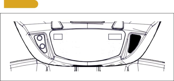
Console Display
LED Display
1
 4
4
2
5
3
1 |
Left enunciator |
Displays Time, BPM, or Weight. |
2 |
Left data readout |
Displays value of Time, BPM, or Weight. |
3 |
Bar graph |
Displays workout profiles and setup options. |
4 |
Right enunciator |
Displays Calories, SPM, or Cal/Hour. |
5 |
Right data readout |
Displays value of Calories, SPM, or Cal/Hour. |
E3 View Monitor
17
Cybex Service Manual
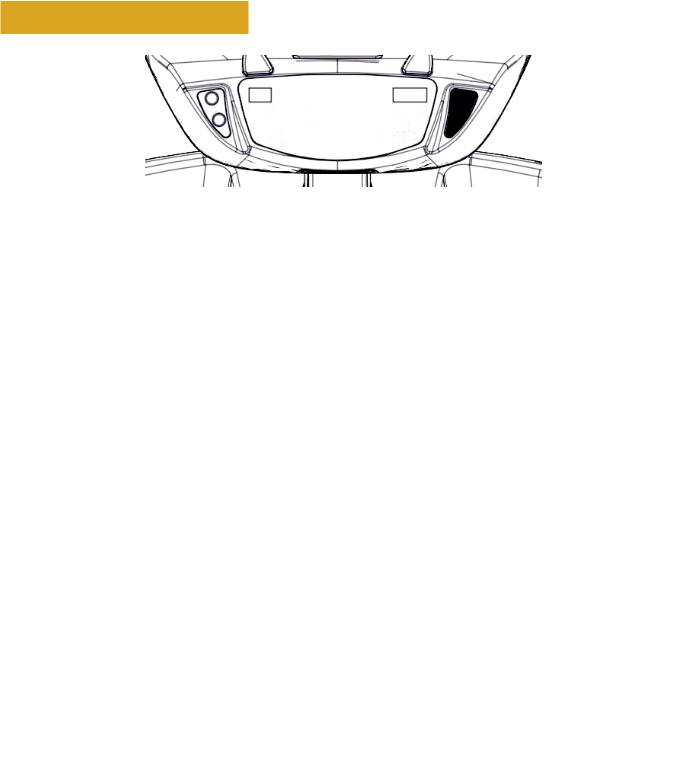
User Controls
1 |
2 |
3 |
4 |
5 |
6 |
7 |
8 |
9 |
10 |
11 |
12 |
13 |
1 |
Incline keys |
2 |
Incline display |
3 |
Quick Start key |
4 |
Workouts key |
5 |
Resistance display |
6 |
Resistance keys |
7 |
Volume keys |
8 |
Display option key |
9 |
Headphone jack |
10 |
STOP key |
11 |
Setup key |
12 |
Enter key |
13 |
Up/Down keys |
Displays — Incline and Resistance are shown in the LED displays.
Keys — User controls for Incline, Quick Start, Workouts, Resistance, Volume, Scan, STOP, Setup, Enter and Up/Down.
18
Cybex Service Manual
User Control Symbols Used
|
|
|
|
|
|
|
|
|
|
|
|
|
|
|
|
|
|
|
|
|
|
|
|
|
|
|
|
|
|
|
|
|
|
|
|
|
|
|
|
|
|
|
|
|
|
|
|
|
|
|
|
|
|
|
|
|
|
|
|
|
|
|
|
|
|
|
|
|
|
|
|
|
|
|
|
|
|
|
|
|
|
|
|
|
|
|
|
|
|
|
|
|
|
|
|
|
|
|
|
|
|
|
|
|
|
|
|
|
|
|
|
|
|
|
|
|
|
|
|
|
|
|
|
|
|
|
|
|
|
|
|
|
|
|
|
|
|
|
|
|
|
|
|
|
|
|
|
|
|
|
|
|
|
|
|
|
|
|
|
|
|
|
|
|
|
|
|
|
|
|
|
|
|
|
|
|
|
|
|
|
Control |
Control Name |
Description |
|||||||||||
|
|
|
|
INCLINE UP |
Adjust Incline up |
|||||||||
|
|
|
|
|||||||||||
|
|
|
|
|
|
|||||||||
|
|
|
|
|
|
|
|
|
|
|
|
|
|
|
|
|
|
|
INCLINE DOWN |
Adjust Incline down |
|||||||||
|
|
|
|
|||||||||||
|
|
|
|
|
|
|||||||||
|
|
|
|
|
|
|
|
|
|
|
|
|
|
|
|
|
|
|
RESISTANCE UP |
Adjust Resistance up |
|||||||||
|
|
|
|
|||||||||||
|
|
|
|
|
|
|||||||||
|
|
|
|
|
|
|
|
|
|
|
|
|
|
|
|
|
|
|
RESISTANCE DOWN |
Adjust Resistance down |
|||||||||
|
|
|
|
|||||||||||
|
|
|
|
|
|
|||||||||
|
|
|
|
|
|
|
|
|
|
|
|
|
|
|
|
|
|
|
VOLUME UP |
Adjust Volume up |
|||||||||
|
|
|
|
|||||||||||
|
|
|
|
|
|
|||||||||
|
|
|
|
|
|
|
|
|
|
|
|
|
|
|
|
|
|
|
VOLUME DOWN |
Adjust Volume down |
|||||||||
|
|
|
|
|||||||||||
|
|
|
|
|
|
|||||||||
|
|
|
|
|
|
|
|
|
|
|
|
|
|
|
|
|
|
|
UP KEY |
Adjust Time, Level, Weight, or Workout up |
|||||||||
|
|
|
|
|||||||||||
|
|
|
|
|
|
A/V - Channel UP |
||||||||
|
|
|
|
|
|
iPod - NEXT track (option) |
||||||||
|
|
|
|
|
|
|||||||||
|
|
|
|
DOWN KEY |
Adjust Time, Level, Weight, or Workout down |
|||||||||
|
|
|
|
|||||||||||
|
|
|
|
|
|
A/V - Channel DOWN |
||||||||
|
|
|
|
|
|
iPod - PREVIOUS track (option) |
||||||||
|
|
|
|
|
|
|||||||||
|
|
|
|
STOP |
Press STOP to end the workout session. If pause |
|||||||||
|
|
|
|
|||||||||||
|
|
|
|
|
|
feature is enabled, press STOP once to enter pause |
||||||||
|
|
|
|
|
|
mode. |
||||||||
|
|
|
|
|
|
|||||||||
19
Cybex Service Manual
Setup
Use the following instructions to setup the units settings.
1.Plug the power cord into a power outlet from a grounded circuit, See Electrical Requirements. Coil up the remainder of the power cord and place it out of the way.
2.Toggle the on/off (I/O) power switch under the front end of the unit to the on position (I). The control panel will light up.
3.Hold the handrails to steady self while stepping into the foot plates.
4.Begin striding.
Time and Date confirmation
The first time the unit is turned on, it prompts the user to confirm the current Time and Date. Quick
Start, Workouts, Setup or Stop will skip this requirement but it will appear again the next time the unit is powered up until the time and date are properly set.
1.Press the ENTER  key to begin editing the time, starting with the hours (HH) and then minutes (MM) and then AM/PM/24.
2.Press the UP  and DOWN
  keys to select the hour.
3.Press the ENTER  key to accept and begin editing the minutes.
4.Press the UP  and DOWN
  keys to select the minutes.
5.Press the ENTER  key to accept and begin editing the AM/PM/24 hour setting.
6.Press the ENTER  key to accept time.
Continue this procedure for the Date. Date format is [YYYY] [MM] [DD]. Y - Year, M - Month and D -
Day.
7.Press the ENTER  key after the final setting for Day. The opening screen will now be displayed.
Time and Date confirmation complete.
Setup options
1.Press and the hold the Display option  and UP
  keys for 3 seconds.
2.Navigate through the setup menu with the UP  and DOWN
  keys.
keys.
20
Cybex Service Manual
3.Press the ENTER  key once to enter setup values. Press again to save any changes and advance forward in the menu.
The Setup options are:
|
LED Console |
E3 View Monitor |
Time |
Set time display format AM, PM, or 24. Set time in Hours and Minutes HH:MM. |
|
Date |
Year format is Y - Year [YYYY]. |
Date format is [YYYY] [MM] [DD]. Y - |
|
Month format is M - Month [MM]. |
Year, M - Month, and D - Day. |
|
Day format is D - Day [DD]. |
|
Weight and |
LbS - Pounds, Kg - Kilograms or |
LBS - Pounds, Kg - Kilograms or |
Distance Units |
Ston - Stone. |
Stone - Stone. |
|
MI - Miles or KM - Kilometers. |
MI - Miles or KM - Kilometers. |
Pause |
Set time length for Pause. OFF (Default), 1:00, 5:00 or 10:00 minutes. |
|
Max Time |
Set maximum workout time. OFF (Unlimited), 20, 30, 60 (Default), or 120 |
|
|
minutes. |
|
Default Time |
Set default workout time. 30, 60 (Default), 90, 120 miutes, off. or club*. |
|
Max Time |
Set maximum workout time. OFF (Unlimited), 20, 30, 40, 50, 60 (Default), 90 or |
|
|
120 minutes. |
|
Tone |
Toggle console beeper On (Default) or OFF. |
|
Dormant Style |
Not available |
Default, Default with time (Clock |
|
|
shown), Heart only or Energy Saver |
|
|
(All LED’s off except for center dashes |
|
|
on membrane. |
A/V |
Set A/V option. Choices are PEM, UHF, none, or FM (TF/M). See A/V Config |
|
|
and FM Radio Presets for full configuration. If unit ships with E3 View Monitor, |
|
|
this setup option is skipped. |
|
*Club setting limits the workout time to 60 minutes during peak times. Peak times are 5:01 AM to 9:00 AM, and 4:01 PM to 9:00 PM
To reset setup options to default values
1.Press the Display option  key at the first setup option screen (Time). The console will display “[rSEt] [? ]“.
To exit without resetting, press the STOP or ENTER  key.
key.
2. To reset setup options, press the UP  and DOWN
  keys to select “[YES]” and press the
ENTER  key.
key.
Exit Set Up Mode.
1. Press the STOP key to exit Setup options.
21

Cybex Service Manual
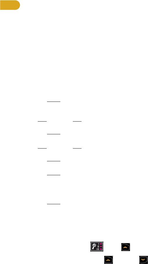
Service Diagnostics
Service diagnostics allows testing, monitoring or altering of unit controls and performance.
1. Press the STOP key several

 .
.
2. |
Press the Display |
|
|
key |
|
and DOWN |
|
key for three seconds. |
||
|
|
|
|
|||||||
|
|
|
|
|||||||
|
|
|
|
|||||||
|
|
|
||||||||
|
|
|
||||||||
|
|
|
|
|||||||
|
|
|
|
|||||||
Navigation while in Statistics or Diagnostic menus: |
|
|
||||||||
Up/Down keys |
|
Scroll up and down in menu. Adjust data values. |
||||||||
Enter |
|
|
Enter and exit menu items, move forward in menu if not required. |
|||||||
STOP |
|
Exit back to Dormant Mode. |
|
|
||||||
Quick Start |
|
Select Diagnostics. |
|
|
|
|
|
|||
Statistics menu: |
|
|
|
|
|
|
|
|
|
|
S1 |
Miles |
Total distance in Miles or Kilometers. |
|
|
||||||
S2 |
Hours |
Total hours of workout time. |
|
|
||||||
S3 |
Starts |
Total number of workout starts. |
|
|
||||||
S4 |
Error Log |
Displays number of errors, up to 20. If no errors are stored “[ 0 ] [Err ] [Log]” will |
||||||||
|
|
be displayed. |
|
|
|
|
|
|||
|
|
To scroll through error log press Enter, then use Up/Down keys. |
||||||||
|
|
When viewing error log use the Enter key to toggle display to Time Stored, Date |
||||||||
|
|
stored, then back to error number. |
|
|
||||||
Reset - While viewing error log press the Display option  key twice.
Press the Quick Start key to exit error log and enter Diagnostics menu.
Press the Enter key to scroll through options.
Diagnostics menu:
T1 |
Test home |
Displays Drive software version, MCC board software version and heart rate |
|
|
board version (POL - Polar or SAL - Salutron). |
|
LED test |
Press Quick Start key to start. A quick LED text begins with lighting the following |
|
|
for three seconds each. Bar Graph Matrix (BGM) LEDs and heart in red, center |
|
|
numerics and heart in green, membrane LED’s and heart in blue. |
|
Key test |
Press Workouts key to start. Test each key by pressing once. Each key press is |
|
|
recognized with a beep, center numeric displays assigned number per key. Press |
|
|
STOP key once to test, hold for two seconds to exit key test. |
T2 |
Brake ID |
Displays which brand of brake/generator is in use. Each one has different output |
|
|
pulses. [PAR] - Paras brand, [C-H] - Chi Hua brand. |
T3 |
Load |
Displays the load calibration value at 0 amps, no load. |
|
0 amps |
|
T4 |
Load |
Displays the load calibration value at 1 amp. |
|
1 amp |
|
22

Cybex Service Manual
Press the STOP key to return to Dormant Mode. If drive motor was running press the STOP key again.
Error Codes
Error codes notify user of a problem condition and are displayed on the console. Error codes can also help to indicate the part of the unit most likely to be causing the problem.
1. Press the STOP key several

 .
.
2. Press the Display |
|
key, |
|
|
|
and Speed Down |
|
key for three seconds. |
|
|
|
|
|
||||
|
|
|
|
|||||
|
|
|
|
|||||
|
|
|
|
|||||
|
|
|
|
|
3.Press the Up/Down keys until Error Log is displayed. Total number of errors will be displayed.
If three dashes “- - -” are shown, the error log is empty.
4.Press ENTER  and use the Up/Down keys to scroll through the error log.
|
Error Code Listing |
Error Code # |
Meaning |
2 |
GFX Communications issue |
4 |
Upper Display comm. issue |
5 |
Drive comm. issue |
6 |
Membrane fault |
8 |
Approaching Over-Temp |
9 |
MCC Watchdog Triggered |
12 |
Graphics board watchdog |
13 |
Upper display watchdog |
14 |
Drive error unknown |
15 |
Embedded A/V Device failure |
16 |
Membrane fault |
18 |
LCB 12v out of range |
19 |
LCB 3.3v or 50v out of range |
29 |
Controller watchdog tripped |
45 |
AC Incline timeout UP |
46 |
AC Incline timeout DOWN |
23
 Loading...