

Page 1
PC / DNC 1200
User Guide (2D + 3D)
CYBELEC SA Tel. ++ 41 24 447 02 00
RUE DES UTTINS 27 Fax ++ 41 24 447 02 01
CH - 1400 YVERDON-LES-BAINS E-Mail: info@cybelec.ch
SWITZERLAND
V-DOC-12PS23D-EN
Page 2

Information in this document is subject to change without notice, and does not represent
a commitment on the part of CYBELEC SA.
The software described in this document is furnished under a license agreement or nondisclosure
agreement. The software may be used or copied only in accordance with the terms of the agreement. It is
against the law to copy the software on any medium except as specifically allowed in the license or
nondisclosure agreement.
Copyright CYBELEC SA. 1991
All rights reserved.
Important:
This notice explains normal and standard programming operations for the numerical control.
In view of the fact that numerical controls can be equipped with configurable functions by the press
manufacturer for his own specific purposes, please refer to the manufacturer-supplied complementary
instructions regarding the programming of these functions.
Autocad
is a registered trade mark of Autodesk Inc..
CYBELEC is a registred trademark of CYBELEC SA.
Ethernet
is a registered trade mark of Xerox Corporation.
IBM , PC/AT , PC Network , Token Ring Network
are registered trade marks of the International Business Machines Corporation.
MS-DOS
MS-Windows
Novell Netware
is a registered trade mark of Microsoft Corporation.
is a registered trade mark of Microsoft Corporation.
is a registered trade mark of Novell, Incorporated.
Windows NT is a registered trade mark of Microsoft Corporation.
Page 3

S
AFETY AND MAINTENANCE INSTRUCTIONS
The operator must be trained for working with the
machine on which the numerical control is installed.
Improper use of the numerical control can cause
heavy damage on equipment and/or injuries to
people.
Modification of machine parameters can cause
important material damage or lead to irregular
product quality.
The rear panel may only be removed by a qualified
technician (danger of electrocution).
Do not expose the numerical control to excessive
humidity so as to avoid any risk of electrocution and
any deterioration of the equipment.
Make sure the numerical control is disconnected
from the mains power before carrying out any
cleaning. Do not use liquids based on alcohol or
ammoniac.
In case of malfunction of the numerical control, call a
technician.
Do not expose the numerical control to direct sun
rays or any other heat source.
Do not place the numerical control in the
neighbourhood of magnetic equipment such as
transformers, motors or devices which generate
interference (welding machines, etc.)
Replace fan filters at regular intervals so as to avoid
overheating.
SAFETY AND MAINTENANCE INSTRUCTIONS PAGE I
Page 4

This page has been left blank intentionally.
PAGE II USER GUIDE PC/DNC 1200 2D&3D
Page 5

LICENSE AGREEMENT FOR CYBELEC SOFTWARE
GENERAL COPYRIGHT
The CYBELEC software is protected by Copyright, and all the copying rights are reserved.
The CYBELEC software may only be installed and used in authorized equipments (PC or DNC).
The user manuals are also covered by copyright, and all rights to use and to copy are reserved.
This document may not, in whole or in part, be copied, photocopied, reproduced, translated or reduced
without prior consent, in writing, from CYBELEC.
SPECIAL DISKETTE COPYRIGHT
The legal users of this software product are authorized only to copy the contents of the diskette into the
memory of the computer to run the program, and to make one backup copy of the original diskette for
safety purposes in case of loss of the original program.
Unauthorized copying, duplicating, selling or otherwise distributing this product is a violation of the law.
SPECIAL EPROM COPYRIGHT
The CYBELEC DNC and CNC units in which the original software made by CYBELEC has been
replaced by a copy not made by CYBELEC, and without written authorization of CYBELEC, will
immediately lose their warranty.
WARRANTY
CYBELEC does not warrant that its software products will function properly in every computer and
programming environment.
The limitations of use of a software product and its technical specifications are decided by CYBELEC
only; CYBELEC solely is entitled to decide upon conformity and performance of a given software.
The CYBELEC software does not compensate for incompatibilities in operating system revisions or
versions.
Running the CYBELEC software under various revisions or versions, or switching between different
versions or revisions may result in loss or alteration of data.
LICENSE AGREEMENT PAGE III
Page 6

SOFTWARE UPDATE SERVICE
Purchase of the CYBELEC software entitles the user, during one year, to delivery of software updates of
the "correction" type.
During the use of a revised or corrected version of the software it may occur that data (program,
parameters, etc.) is lost, or that the equipment or its connections need to be modified; these effects are not
always foreseeable and do not engage CYBELEC's responsibility.
TERMINATION
This agreement shall automatically terminate upon any act of bankruptcy by or against licensee, upon any
assignment for the benefit of creditors of the licensee, upon any attachment execution of judgement or
process against licensee or its assets that substantially inhibits its ability to do business, or upon
dissolution of licensee.
CYBELEC has the right to terminate this agreement immediately, should the licensee violate the
aforementioned conditions.
Within 30 days of termination of this agreement for any reason, licensee shall at his option, either:
return to CYBELEC or authorized dealer all existent copies of such software and related materials, or
furnish to CYBELEC evidence satisfactory that the original and all copies of the software, in whole
and in any form, have been destroyed.
LIMITATION OF LIABILITY
The foregoing warranty is instead of all other warranties, expressed or implied.
Licensee further agrees that CYBELEC shall not be liable for any lost profits, lost savings, loss of use, or
other incidental or consequential damages arising from the use or inability to use the software, or for any
claim or demand against licensee by any other party.
In no event shall CYBELEC be liable for consequential damages, even if CYBELEC has been advised of
the possibility of such damages.
CYBELEC does not warrant that the functions contained in the software will meet the licensee's
requirement or that the operation of the software will be totally error free.
Should the software prove defective, the licensee (and not CYBELEC or an authorized dealer or
representative) will assume the entire cost of all necessary service, repair or correction.
CYBELEC warrants the diskettes, EPROMS or other magnetic support or cassettes on which the
programs are supplied to be free of defects in material and workmanship under normal use for a period of
90 days from the date of shipment to the licensee as evidenced by a copy of the packing slip.
PAGE IV LICENSE AGREEMENT
Page 7

LIMITATION OF REMEDIES
CYBELEC's entire liability and the licensee's exclusive remedy shall be as follows:
The replacement of any diskettes or EPROMS or magnetic support media or cassettes not meeting
CYBELEC's limited warranty and which materials are returned to CYBELEC or an authorized
CYBELEC representative with a copy of the packing slip, or
If CYBELEC or its representative is unable to deliver replacement diskettes, magnetic support media,
EPROM or cassettes which are free of defects in materials or workmanship, the licensee may terminate
this agreement under the terms and conditions herein mentioned, and the purchaser's money will be
refunded.
GENERAL
The licensee acknowledges that he has read this agreement, understands it and agrees to be bound by its
terms and conditions.
The licensee agrees to hold CYBELEC harmless on all liability associated with licensee's breach of this
agreement including, but not limited to, all reasonable attorney's fees and court costs, if any.
This license agreement shall be governed by Swiss law; place of jurisdiction is Lausanne, Switzerland.
MAINTENANCE
CYBELEC will provide one year of software maintenance.The extent of maintenance, and response time
for furnishing same, shall be at the sole discretion of CYBELEC.Maintenance shall normally include
correction of errors in code, correction of errors in supporting documentation, update versions of the
covered software which may be released by CYBELEC during the maintenance period.
In no event shall CYBELEC be obliged to provide technical support in attempting to resolve problems or
difficulties resulting from licensee's modification of the licensed software; any such modification by
licensee is entirely at licensee's own risk.
LICENSE AGREEMENT PAGE V
Page 8

This page has been left blank intentionally.
PAGE VI LICENSE AGREEMENT
Page 9

March 2002 V. 2.3
CONTENTS
SAFETY AND MAINTENANCE INSTRUCTIONS ...........................................................................I
LICENSE AGREEMENT FOR CYBELEC SOFTWARE..................................................................III
INTRODUCTION..............................................................................................................................5
Safety, Copyright & License agreement..............................................................................5
DNC with Windows operating system 5
About this Manual................................................................................................................6
Software Installation ............................................................................................................7
Typographical Conventions.................................................................................................7
Definitions............................................................................................................................7
QUICK START .................................................................................................................................9
Leaving the Software 10
L-ALPHA (2D) PROGRAMMING .....................................................................................................11
Step by Step ........................................................................................................................12
Clear the Work Zone 12
Punch Adjustment 13
Die Adjustment 15
Choice of Tools 16
General Data 18
Programming Section 1 18
Programming Section 2 19
Product Calculation 21
Bending Range (BEND 2D) 21
Position of Axes, other Functions 23
DIRECT PROGRAMMING (BEND NUM) ........................................................................................25
Step by Step ........................................................................................................................26
Clear the Work Zone 26
General Data 27
Choice of Tools 28
Entering the Data (1) 28
Entering the Data (2) 30
BENDING, TESTS AND CORRECTIONS.......................................................................................33
12QS23DWIN_EN.DOC
CONTENTS PAGE 1
Page 10

3D PROGRAMMING ....................................................................................................................... 35
Creation of the Product....................................................................................................... 35
Step by Step ....................................................................................................................... 36
Clear the Work Zone 36
MEMORIZE OR SEARCH A PRODUCT ........................................................................................ 43
Memorize a Product ........................................................................................................... 43
Search a Product................................................................................................................44
Organization of the Memories ............................................................................................ 48
PROTECTION OF THE ACCESS LEVELS .................................................................................... 49
General Information............................................................................................................ 49
The Users ........................................................................................................................... 50
Access by Password .......................................................................................................... 51
Access to Levels superior to 3............................................................................................ 52
Change Password .............................................................................................................. 53
Password forgotten 54
BRIEF OVERVIEW OF THE PAGES.............................................................................................. 57
Menu Page ......................................................................................................................... 57
List of Products Page ......................................................................................................... 57
List of Graphical Products Page......................................................................................... 58
Product / Criteria Search Page........................................................................................... 58
Transfer Page ..................................................................................................................... 58
List of Punches Page.......................................................................................................... 59
List of Dies Page................................................................................................................. 59
Punch Programming Page ................................................................................................. 60
Die Programming Page ...................................................................................................... 60
Welcome Page ................................................................................................................... 61
Initialization Page................................................................................................................ 61
Machine Parameters Page ................................................................................................. 62
Product Num Page ............................................................................................................. 62
Tools Position Page............................................................................................................ 63
Comments Page ................................................................................................................. 63
Bend Numerical Page......................................................................................................... 64
Bend 2D Page ....................................................................................................................64
Bend 3D Page ....................................................................................................................65
Bend Function Page ........................................................................................................... 65
Bend. Tools Page ............................................................................................................... 66
Corrections Page................................................................................................................66
INSTALLATION OF THE PC/DNC 1200 SOFTWARE ................................................................... 67
PC Protection key ...............................................................................................................67
Minimum configuration ....................................................................................................... 69
Software support PC 1200 Windows.................................................................................. 69
Software support DNC 1200 Windows............................................................................... 69
Software support DNC 1200 DOS...................................................................................... 70
INSTALLATION OF PC1200 WINDOWS ....................................................................................... 71
INSTALLATION OF PC1200 / PC900 DOS VERSION................................................................... 73
Installation of DNC Windows .............................................................................................. 74
PAGE 2 USER GUIDE PC/DNC 1200 2D&3D
Page 11

If the keyboard of the DNC doesn't work: 74
Installation of DNC DOS......................................................................................................75
If the keyboard of the DNC doesn't work: 76
INDEX ..............................................................................................................................................77
CONTENTS PAGE 3
Page 12

This page has been left blank intentionally.
PAGE 4 USER GUIDE PC/DNC 1200 2D&3D
Page 13

I
NTRODUCTION
AFETY
S
, C
DNC WITH WINDOWS OPERATING SYSTEM
OPYRIGHT
Please consult the safety instructions, copyright and license agreement on the
first pages of the manual.
The CYBELEC DNCs equipped with Windows have been installed in the
factory with a configuration especially realised for the numerical control
(see technical information).
This configuration ensures that a minimum of files are present on the DNC,
offering in this way a maximum speed to execute the programs. This
configuration also ensures that the drivers are correct and that the whole
guarantees an optimal functioning of the numerical control.
ICENSE AGREEMENT
& L
As Windows is a very open system, it is advised to not modify the Windows
installation nor to install other programs. You risk to disturb the functioning
of the the numerical control.
If you wish to install a network or a printer, please call a specialist.
Remember that the DNC is equipped with a CD-ROM reader and that it is
very easy or even tempting to install external softwares, utilities or games
coming from specialized magazines.
CYBELEC accepts no responsibility in case of misfunctioning of
the numerical control if other programs have been installed or if
the original configuration has been modified.
We also remind you that the Windows environment is infested with virus and
utmost caution is to be taken when using data or softwares coming from
outside. A regular back-up enables you to get your data in safety.
We certify that our numerical controls are delivered virus free.
INTRODUCTION PAGE 5
Page 14

BOUT THIS MANUAL
A
This User Guide treats some simple examples, in order to rapidly acquire the
programming concept.
The Reference manual furnishes supplementary information to this
document.
Remark: In this manual, it is assumed that the DNC has an operational
This manual describes the software version U3 or higher.
This manual can evolve, it is you, the operators, who can contribute to help
you more. If you have any remarks concerning this manual, please write to us
at:
configuration (i.e. machine parameters and tools are
programmed).
Some represented figures can possibly not correspond with
previous versions.
CYBELEC S.A.
Dpt Communication
Rue des Uttins 27
CH-1401 Yverdon-les-Bains
Fax ++ 41 24 447 02 01
@
E-Mail: info
cybelec.ch
PAGE 6 USER GUIDE PC/DNC 1200 2D&3D
Page 15
OFTWARE INSTALLATION
S
See at the end of this manual, page 67.
YPOGRAPHICAL CONVENTIONS
T
Arial bold Quotations of text as seen on the screen.
Arial bold italic Used to indicate the name of a DNC input or
Italic Reference to a written element, a paragraph or a
Indicates a double click on the key.
output.
manual.
For example: See Typographical Conventions.
EFINITIONS
D
In this manual the following terms are used:
Select This term designates a choice operation.
According to the situation the choice can be
done in different ways.
To validate a field, just leave the field or press
the
The word "select" will also be used to reach a
specific page.
Point out Position the cursor on the described point.
Use therefore the cursor keys
Mouse/Tracksensor Means a mouse for a PC,
a tracksensor for a DNC.
Click Press the left tracksensor button.
Click right Press the right tracksensor button.
Click left/right Press simultaneously the left and right
tracksensor buttons.
(Enter) key.
or the tracksensor.
Round robin lists or multiple choice fields:
They are violet coloured and signify that several
options are available.
The choice of the content is made by pressing
the
INTRODUCTION PAGE 7
key or click right.
Page 16
A window appears with the list of the available
choices for this field.
To validate the choice:
- enter the number indicated next to the choice
or
- place the cursor on the choice and press the
key.
It is possible, without displaying the choice
window, to make appear one after the other the
choices by pressing the
key.
To validate, leave the field.
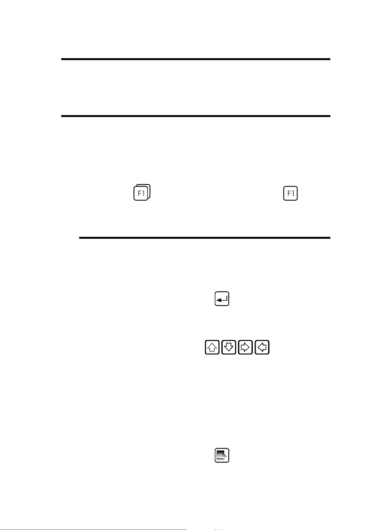
Menu Designates the main menu page which can be
reached by pressing the key.
A choice window "Menu Menuname" is also
called when pressing one of the
to
keys.
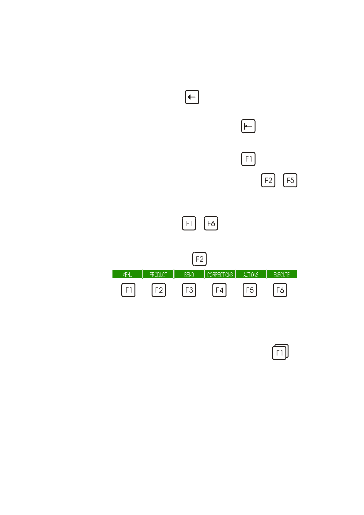
Function key Each time you are asked to press a function key
to , the corresponding menu
appears.
Generally the name of the function key is used.
For example: press PIECE designates the
key
.
Rapid validation To facilitate the operator's work, the DNC
For more information, see the same paragraph in the Reference Manual.
PAGE 8 USER GUIDE PC/DNC 1200 2D&3D
memorizes the last choice made in a menu.
To validate a menu option quickly, simply
double click on a function key (e.g.:
to validate directly the last page selected.
),
Page 17

Q
UICK START
This chapter describes, by means of some simple examples, diverse ways of
using your DNC.
L-alpha Programming.
This method is the fastest and the most currently used in the workshop
when the operator has to create himself a product from a paper
drawing.
Direct Programming.
This type of programming is often used for simple products or by
operators having worked on conventional pressbrakes without
numerical controls.
This page is very close to what an operator has to do, since he has on
one single screen all the information and fields necessary for the
programming of his product.
3D Programming.
This type of programming enables the user to visualize the
construction of its product in 3D. This mode also enables more
elaborated constructions and modifications than in 2D mode.
We assume in this part that all the necessary tools have already been
programmed as well as the machine parameters.
Access levels We presume that the operator knows how to reach level 1, or that the key of
the front panel (option) is on position 1. Should this not be the case, see
chapter Protection of the Access Levels further in this manual.
The screens of this manual have been captured with the PC 1200 Windows
software. The screens however are identical in the DNC 1200 2D.
Reminder:
You will find the correspondence between the keys of the DNC and those of
a PC keyboard in the 2D Reference Manual under External keyboard.
These procedures indicate to the operator a programming method
recommended by CYBELEC, enabling to assimilate by the example the
functioning of the software.
For additional information, please consult the 2D Reference Manual and/or
the 3D Reference Manual, which each contains a table of contents and a
detailed index facilitating the search for information.
QUICK START PAGE 9
Page 18

LEAVING THE SOFTWARE
It is possible at any time to quit the task after having memorized the current
state. However it is important to leave the software in the correct way by
calling up the MENU page
The same procedure can be used on the PC software, or press the
keys on any page.
and pressing the QUIT key.
+
PAGE 10 USER GUIDE PC/DNC 1200 2D&3D
Page 19

L-
ALPHA
(2D) P
This chapter describes, by means of a concrete example, how to create a
product by using the "L-alpha" method (length-angle).
This method is fast and easy and allows to display the product in 2D, which
usually is sufficient when products are being programmed in the workshop.
The product being used as an example is composed of 2 sections (profiles),
but the procedure is identical for one or several sections.
0
.
0
0
2
ROGRAMMING
40.0
3
0
.
0
45.0
15
0.
0
2
0
.
0
The side flaps with the oblong holes, which are included in section 1, will be
made first, so that a punch of identical length as that for section 2 can be
used.
To make this product, we will use 2 mm thick ST37 type steel.
L-ALPHA PROGRAMMING PAGE 11
Page 20

TEP BY STEP
S
CLEAR THE WORK ZONE
The user has to clear the work memory before creating a new product.
Call the PRODUCT NUMERICAL page, which enables the data
introduction in L-Alpha mode.
Clear the work zone to
create a new product
Press the PRODUCT
Select PRODUCT NUMERICAL. For that, enter the number
indicated next to the choice
or place the cursor on the choice and press
or click on the choice.
The figure below shows the PRODUCT NUMERICAL page containing a
previous product.
function key.
key
PAGE 12 USER GUIDE PC/DNC 1200 2D&3D
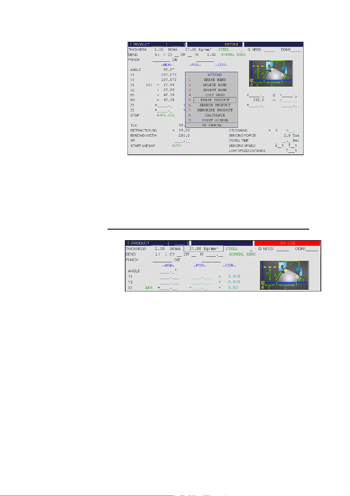
Page 21

Press the ACTION
Select ERASE PRODUCT. For that, enter the number indicated next
to the choice
or place the cursor on the choice and press
or click on the choice, and then CONFIRM (
This operation erases only the data of the work memory. That means that the
product which is possibly located in the work memory is not lost if it has
been saved beforehand.
key.
key
).
PUNCH ADJUSTMENT
Punch adjustment
Window without any
tools selection
This chapter as well as the following Die Adjustment are optional when
programming in 2D mode.
It is interesting to look them over, for the TOOLS POSITION page enables
to define several places of work and hence to the operator to visualize the
tools assembly.
If the tools assembly is not important, skip these two chapters.
The tools definition will be made directly in the PRODUCT NUMERICAL
page (page in which you still are at this stage of the procedure).
Call the TOOLS POSITION page by pressing the PRODUCT
function key and select TOOLS POSITION.
Selection field : P or D
Field L (total available length)
L-ALPHA PROGRAMMING PAGE 13
Page 22
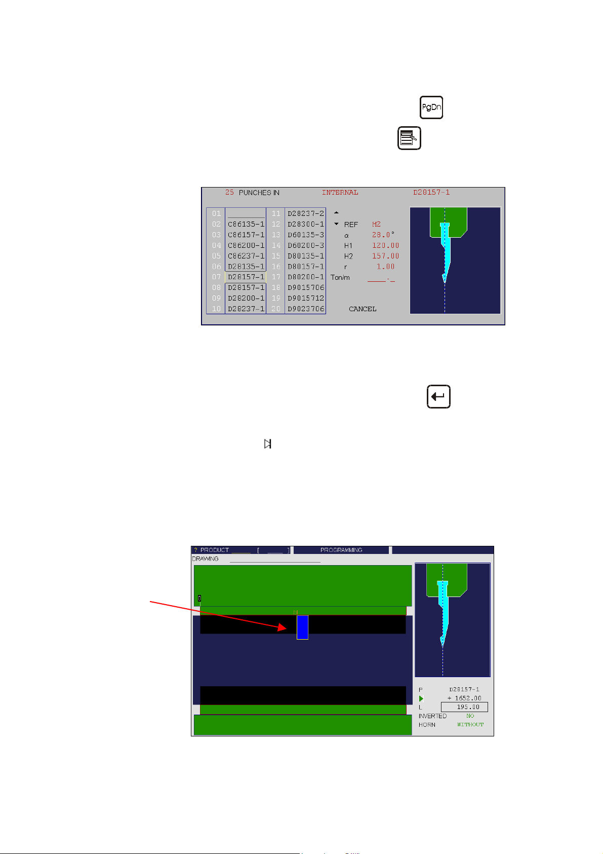
Check that a punch or / and the letter P are displayed in the right-hand
window (selection field).
If there is a die or the letter D, change it using the
Place the cursor on the P field and press the
key.
key to open the
punch LIST OF CHOICES menu.
Select the required punch by entering the number indicated next to the
choice with a two-digit number. Example: 01 for 1, 02 for 2, etc…
or
Place the cursor on the choice and validate with the
key
or
Click on the requested choice.
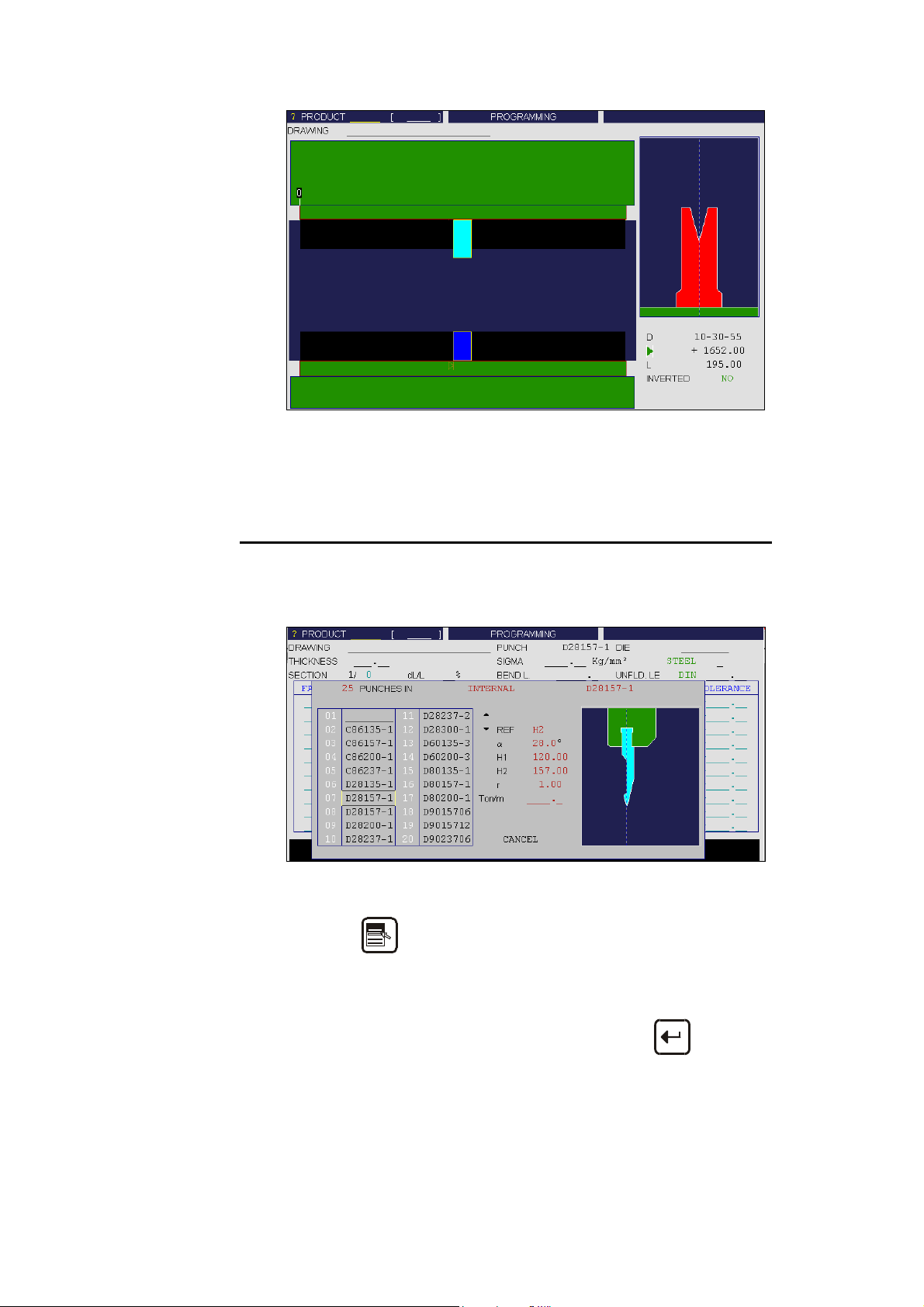
Punch adjustment
Punch placed in the
middle of the machine
Modify the
field by introducing a value equal to the half of field L
minus the half of the tool length, which corresponds to the central
point of the machine on which the punch is fixed. (In our example:
3500/2 – 195/2 = 1652.5 mm).
Modifiy the L field by introducing the value of 195 mm which
corresponds to the required tool length. In the front view the selected
tool appears in dark blue.
PAGE 14 USER GUIDE PC/DNC 1200 2D&3D
Page 23

DIE ADJUSTMENT
Die adjustment
Window with punch
selection but without
die
Same remark as for Punch Adjustment.
Selection field : D
Stay on TOOLS POSITION page.
Select the die using the
Place the cursor on the D field and press the
die choice menu.
Select the required die by entering the number indicated next to the
choice with a two-digit number. Example: 01 for 1, 02 for 2, etc…
or
Place the cursor on the choice and validate with the
or
Click on the requested choice.
key.
key to open the
key
Modify the
minus the half of the tool length, which corresponds to the central
point of the machine on which the die is fixed. (In our example:
3500/2 – 195/2 = 1652.5 mm).
Modify the L field by introducing the value of 195 mm which
corresponds to the required tool length.
L-ALPHA PROGRAMMING PAGE 15
field by introducing a value equal to the half of field L
Page 24
Die adjustment
Final mounting of the
tools
Window with selection
of the punch and the
die
Return to the PRODUCT NUMERICAL page via the PRODUCT
menu.
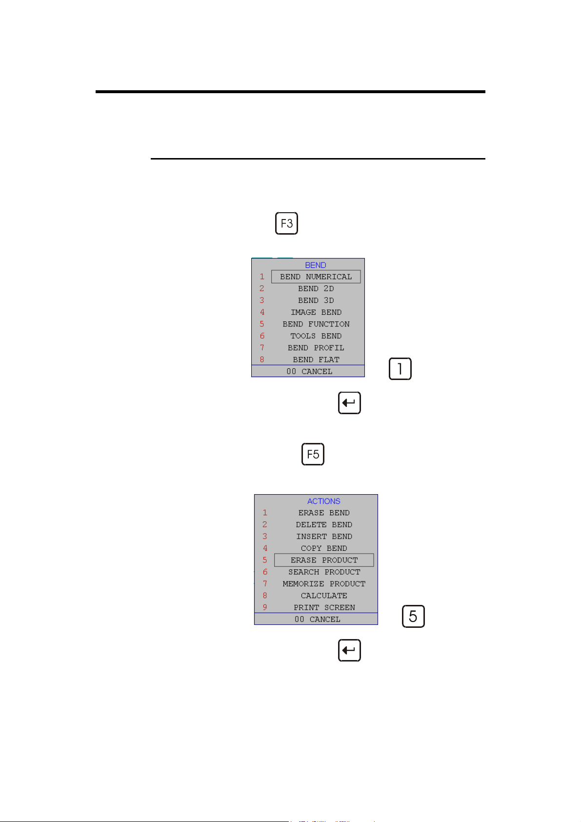
Choice of tools
CHOICE OF TOOLS
As mentioned above, if the tools position is not indispensable, you can define
the tools directly in the PRODUCT NUMERICAL page.
Cursor on PUNCH field (upper part of the screen)*.
Key or right click to display the LIST OF CHOICES.
Select the desired tool by by entering the number indicated next to the
choice with a two-digit number. Example: 01 for 1, 02 for 2, etc…
or
Place the cursor on the choice and validate with the
or
Click on the desired choice.
PAGE 16 USER GUIDE PC/DNC 1200 2D&3D
key
Page 25

Remark: Each window contains 20 tools. It is possible to reach the
next or previous 20 tools by using respectively the
or
keys.
Each database (punchs and dies) is limited to 200 tools.
You can also call the end of the list by introducing the value
999 or recall the begin of the list by introducing 001.
Proceed in the same way for the DIE.
Remark: It is possible to make the same choice, and in the same way,
in the TOOLS BEND page (via the BEND menu). This
enables to see the tools profile, along with their main
characteristics.
* The PUNCH and DIE fields in the upper part of the screen designate the
general tool for the calculation of the product. If a product is being
programmed via the PRODUCT NUMERICAL page, it is mandatory to
enter these two items.
The PUNCH and DIE columns in the table allow to specify a different tool
for a given bend.
In the BEND NUMERICAL page, there are also a PUNCH and a DIE field.
If the product has been programmed via the PRODUCT NUMERICAL
page, these fields will be empty or partially filled if tools have been entered
in the corresponding columns of the table of the PRODUCT NUMERICAL
page. This is so because these fields correspond to the ones in the table.
(Also see the section Direct Programming (BEND NUM) further in this
manual).
L-ALPHA PROGRAMMING PAGE 17
Page 26

GENERAL DATA
Enter:
- the punch
- the die
- the sigma/material
- the type of material
- the bending length
PROGRAMMING SECTION 1
Place the cursor on the THICKNESS field and enter the thickness of
the material being used.
Place the cursor on the SIGMA field and introduce the force/mm² of
the material used. (E.g.: Steel = 37 Kg/mm²)
Leave the round-robin list on STEEL.
Place the cursor on the BEND L. field and introduce the bending
length for the product (section 1 = 150.0 mm).
The dimensions of the faces are given in external cotation according to DIN.
See 2D Reference Manual, section Unfolded length.
45.0
45.0
When introducing the data in L-Alpha mode, just "begin" the profile by one
of the extremities and furnish one after the other the values of each face and
angle. At the last face there is no angle corresponding to.
Remark: As shown in the following figure, the profile of section 1 is
automatically drawn as a function of the introduced data
(length and angle), thus the value of the internal radius is
automatically calculated.
90.0°
45.0
90.0°
200.0
200.0
200.0
45.0
90.0°
45.0
90.0°
PAGE 18 USER GUIDE PC/DNC 1200 2D&3D
Page 27

Section 1
Automatically drawn profile
Procedure:
Place the cursor on the first field of the LENGTH column and
introduce the value of 45 mm which corresponds to the first length.
Place the cursor on the first field of the ANGLE column and introduce
the value of 90° which corresponds to the first angle to be bent.
Place the cursor on the second field of the LENGTH column and
introduce the value of 200 mm which corresponds to the second
length.
Place the cursor on the second field of the ANGLE column and
introduce the value of 90° which corresponds to the second angle to
be bent.
Place the cursor on the third field of the LENGTH column and
introduce the value of 45 mm which corresponds to the last length
before the edge of the product.
Hint: Introduce first all the lengths and then the angles. This way of operating is
much faster.
PROGRAMMING SECTION 2
The definition of the bending direction is done by inversing the angle sign,
however the choice of the side is arbitrary, but has to be constant for the
whole profile of the product.
45.0
-90.0°
45.0
90.0°
150.0
or
45.0
90.0°
45.0
-90.0°
150.0
L-ALPHA PROGRAMMING PAGE 19
-135.0°
20.0
135.0°
20.0
Page 28

Section 2
Procedure:
Stay on PRODUCT NUMERICAL page.
Place the cursor on the SECTION field, enter the value of 2 and leave
the field. This automatically initializes a new page for programming
section 2.
Place the cursor on the BEND L. field and enter the bending length
for this section (200).
Place the cursor on the first field of the LENGTH column and
introduce the value of 30 mm which corresponds to the first length.
Place the cursor on the first field of the ANGLE column and intro-
duce the value of 90° which corresponds to the first angle to be bent.
Place the cursor on the second field of the LENGTH column and
introduce the value of 40 mm which corresponds to the second length.
Place the cursor on the second field of the ANGLE column and
introduce the value of -90° which corresponds to the second angle to
be bent.
Place the cursor on the third field of the LENGTH column and
introduce the value of 150 mm which corresponds to the third length.
Place the cursor on the third field of the ANGLE column and
introduce the value of 135° which corresponds to the third angle to be
bent.
Place the cursor on the fourth field of the LENGTH column and
introduce the value of 20 which corresponds to the last length before
the edge of the product.
Remark: As shown in the previous figure, the profile of section 2 is
automatically drawn as a function of the introduced data
(length and angle), thus the value of the internal radius is
automatically calculated. The unfolded length too is
calculated.
PAGE 20 USER GUIDE PC/DNC 1200 2D&3D
Page 29

Calculation of the
unfolded lengths
PRODUCT CALCULATION
Stay on the PRODUCT NUMERICAL page.
Select CALCULATE in the ACTION menu.
The message CALCULATING... appears in the interactive field on
the top right-hand corner of the screen.
The data in the UNFLD. LE. DIN (Length of the unfolded sheet) and
Ri (Internal radius) fields appears.
Remark: If the CALCULATE function key is not activated, the
calculation will be carried out automatically as soon as an
other screen page is being accessed.
This function is to use for the software versions previous to
U2.
Searching for the
bending range
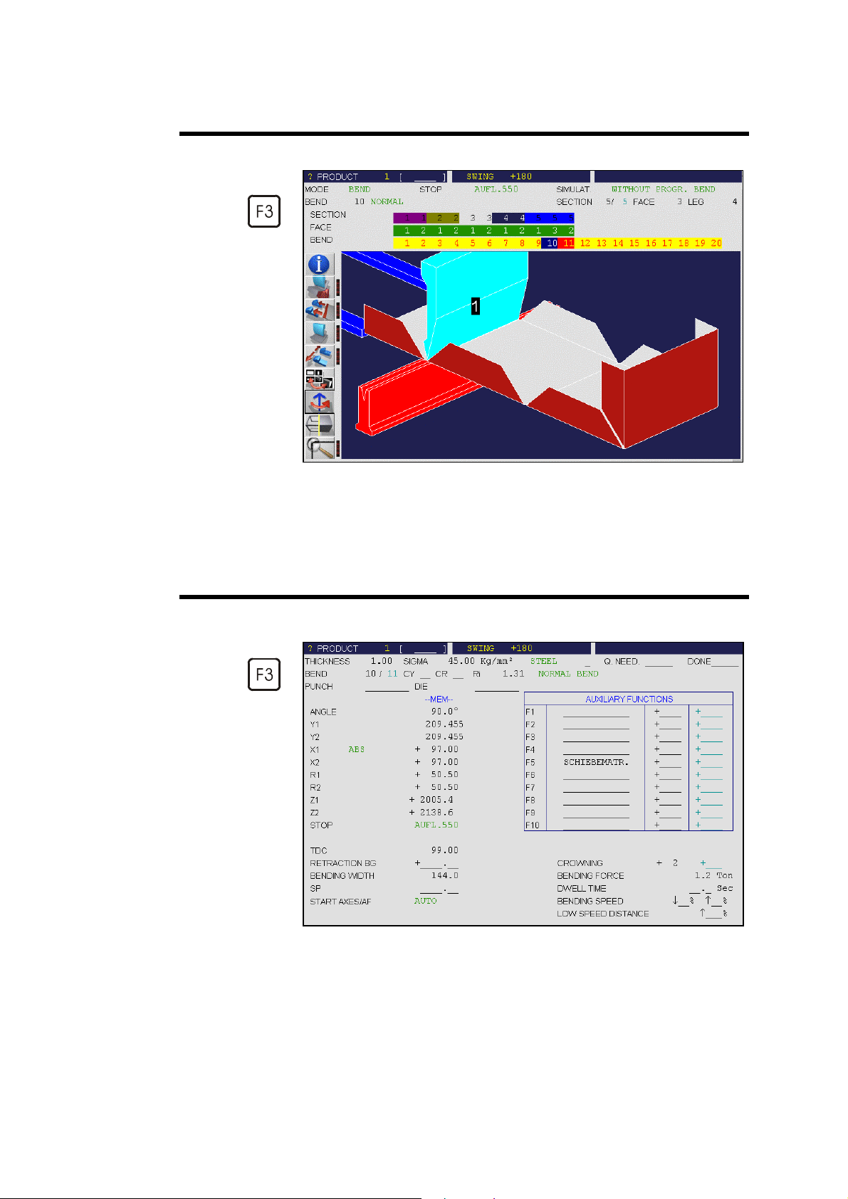
BENDING RANGE (BEND 2D)
Call the BEND 2D page (BEND menu).
In the SIMULAT. field, choose the option WITHOUT PROGR.
BENDS.
In the ACTION menu, choose SEARCH BENDING RANGE.
The message SIMULATING RUNS…, then CALCULATING...
appears in the interactive field on the top right-hand corner of the
screen.
L-ALPHA PROGRAMMING PAGE 21
Page 30

After this the succession of sequences can be visualized using the
Pg Dn
and
keys.
In the just programmed example we can see that the searching for the
bending range has first placed the section 1, and then the section 2.
The operator has the possibility to modify the bending range (see the
corresponding chapter in the 2D Reference Manual) or to ask the software to
respect specific criteria like minimum of swings or returns. For that, please
refer to the 2D Reference Manual, section Simulation criteria.
In case where the software program does not find any solution, the bending
range must be imposed manually.
See Bending order in the 2D Reference Manual.
PAGE 22 USER GUIDE PC/DNC 1200 2D&3D
Page 31

POSITION OF AXES, OTHER FUNCTIONS
Menu BEND, page BEND NUMERICAL.
It can be seen that the axis position, the bending force, the crowning and, if
applicable, the retraction and the top dead centre (depending on how they
have been defined in the machine parameters) are calculated automatically.
These values can be modified by the operator.
According to his needs, the operator can modify the following items:
TDC
RETRACTION BG
SP
DWELL TIME
BENDING SPEED
LOW SPEED
DISTANCE
Complementary explications are found in the 2D Reference Manual.
To execute the product, see the Bending, Tests and Corrections section,
page 33.
the Top Dead Center. If not programmed, the
beam will rise to the maximum TDC.
the retraction of the backgauge.
the Switch Point (switching from High Speed
to Bending Speed).
the time during which pressure is being
maintained.
the bending speed downward, or the speed
during the upward moving phase until the
clamping point is reached.
allows to define that only a portion (expressed
in %) of the upward movement between the
TDC and the clamping point will be carried out
at low speed; the continuation of the upward
movement is made at high speed.
L-ALPHA PROGRAMMING PAGE 23
Page 32

This page has been left blank intentionally.
PAGE 24 USER GUIDE PC/DNC 1200 2D&3D
Page 33

D
IRECT PROGRAMMING
SECTION 2
40.0
(BEND NUM)
This type of programming is often used for simple products or by operators
having worked on conventional pressbrakes without numerical controls.
This page is very userfriendly, for the operator has on one single screen all
the information and fields necessary for the programming of his product.
SECTION 1
0
.
0
0
2
3
0
.
0
45.0
15
0.
0
2
0
.
0
The bending order is choosen by the operator, since he programs directly
each bend.
In this example, we first realize the side flaps with the oblong holes, which
are included in section 1, so that a punch of identical length as that for
section 2 can be used.
To make this product, we will use 2 mm thick ST37 type steel.
DIRECT PROGRAMMING PAGE 25
Page 34
TEP BY STEP
S
CLEAR THE WORK ZONE
The user has to clear the work memory before creating a new product.
Call the BEND NUMERICAL page.
Press the BEND
Select BEND NUMERICAL. For that, enter the number indicated
next to the choice
or
place the cursor on the choice and press
or
click on the choice.
Press the ACTION key .
Choose ERASE PRODUCT. For that, enter the number indicated
function key.
: key
next to the choice
or
place the cursor on the choice and press
or
click on the choice, and then CONFIRM.
PAGE 26 USER GUIDE PC/DNC 1200 2D&3D
: key
Page 35
Clear the work zone to
create a new product
GENERAL DATA
Enter:
- the sigma/material
- the type of material
This operation erases only the data of the work memory. That means that the
product, which is possibly located in the work memory, is not lost if it has
been saved beforehand.
Place the cursor on the THICKNESS field and enter the thickness of
the material being used.
Place the cursor on the SIGMA field and introduce the force/mm² of
the material used. (E.g.: STEEL = 37 Kg/mm²).
Note: It is mandatory to program these data, as well as the tools.
(see following page)
DIRECT PROGRAMMING PAGE 27
Page 36

Choice of tools
CHOICE OF TOOLS
Stay on the BEND NUMERICAL page.
Cursor on the PUNCH field.
Key
Select the desired punch by typing the number situated next to the
choice with a two-digit number. Example: 01 for 1, 02 for 2, etc…
or
Place the cursor on the choice and validate with the
or
Click on the desired choice.
Proceed in the same way for choosing a DIE.
Remark: It is possible to make the same choice, and in the same way, in
or right click to display the CHOICE LIST.
the TOOLS BEND page (via the BEND menu). This enables
to see the tools profile, along with their main characteristics.
ENTERING THE DATA (1)
The conventional way of entering the data is to program in the
BEND NUMERICAL page:
the required angle (the Y depth will be calculated according to the
tools and the material already programmed). It is also possible to
directly enter the Y1 / Y2 values without programming the angle.
key
the real position of the backgauge.
the specific data for the current sequence (top dead center, bending
length and, if necessary, backgauge type, retraction, dwell time, etc.)
PAGE 28 USER GUIDE PC/DNC 1200 2D&3D
Page 37

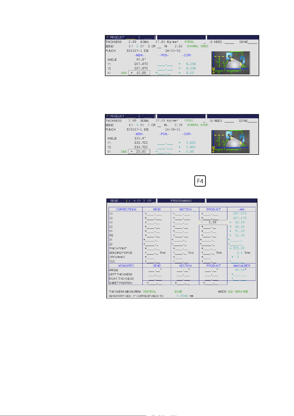
Below is shown the screen with the values for these two bends.
The page shown above illustrates how to program the two flaps with the
oblong holes (section 1).
The two bends being identical, enter 2 in the CY field. Program the angle to
90°, the X axis to its absolute value (43.00) and enter the bending length
(150).
The bending force and the crowning will be calculated automatically.
The operator can, of course, modify these values if necessary.
According to his needs, the operator can also modify:
TDC
the Top Dead Center. If not programmed, the
beam will rise to the maximum TDC.
RETRACTION BG
SP
the retraction of the backgauge.
the Switch Point (switching from High Speed
to Bending Speed).
DWELL TIME
the time during which pressure is being
maintained.
BENDING SPEED
the bending speed downward, or the speed
during the upward moving phase until the
clamping point is reached.
LOW SPEED
DISTANCE
allows to define that only a portion (expressed
in %) of the upward movement between the
TDC and the clamping point will be carried out
at low speed; the continuation of the upward
movement is made at high speed.
DIRECT PROGRAMMING PAGE 29
Page 38
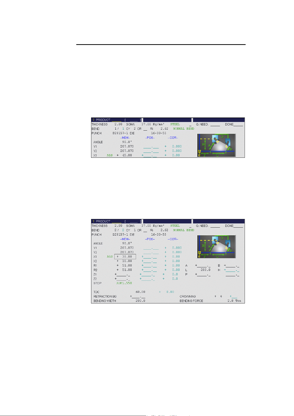
ENTERING THE DATA (2)
HINT The way of programming described above (section Entering the Data (1))
requires of the operator to subtract the steel thickness from the external
dimension of the product. The procedure described below will facilitate the
programming. It has, however, some limitations depending on the product
and the chosen bending order.
The hint consists of entering the external dimension in the X field of the
backgauge, and to program a constant negative correction corresponding to
(approximately, according to your experience, to the tools and to the
material) the material thickness for the entire product.
This procedure is described hereafter:
BEND NUMERICAL page, same remark as underneath the
preceding screen illustration, except for the fact that X has been
programmed with the external dimension, as explained. (45)
This sequence carries out the bending of the two flaps of 45.0 mm
with the oblong holes.
To create the subsequent sequence, press the ACTION key and
choose COPY BEND.
It can be seen that all the data has been copied onto the second
sequence.
Enter the first flap of the second section, i.e. X = 30.00.
Modify the field CY = 1 or leave it unprogrammed.
Modify the bending length (BEND L. = 200) and possibly the other
fields according to your needs.
Press the ACTION key and choose COPY BEND.
PAGE 30 USER GUIDE PC/DNC 1200 2D&3D
Page 39
Program X = 40.00.
Press the ACTION key and choose COPY BEND.
For the last bend, enter ANGLE = 135.0° and X = 20.00.
Call the CORRECTIONS page (key
).
In the PRODUCT column, enter the value to be subtracted from the
external dimension in order to obtain a correct backgauge position
(generally, a value close to the material thickness). In our example, a
value of – 2.00 mm.
DIRECT PROGRAMMING PAGE 31
Page 40

This page has been left blank intentionally.
PAGE 32 USER GUIDE PC/DNC 1200 2D&3D
Page 41

B
ENDING
, T
ESTS AND CORRECTIONS
This chapter explains how to proceed in order to execute a product. This way
of doing is destined only to demonstrate how to use the numerical control.
The testing and adjusting operations can be carried out in the order decided
by the operator.
Go into semi-automatic mode
If necessary, move to the first sequence by means of the
Pg Dn
keys.
Press the start key
sequence.
Carry out the bend with a trial product.
Measure the flap and the obtained angle.
Go to or remain in the CORRECTIONS page.
in order to position the axes on the first
.
or
If necessary, correct the flap (in this example, a correction of
X = - 0.10 is assumed) for the current bend.
Reminder: In the above screen page the correction of -2.00 mm
corresponds to the material thickness programmed in the
example Entering the Data (2) above.
Position the cursor on the ANGLE field, BEND column, and enter
the measured angle (93.0 in this case). The software automatically
calculates the necessary correction (-0.292,which can be seen in the
Y1, Y2 fields, in the BEND column). Also see the 2D Reférence
Manual in the Corrections section.
Carry out a second test bend (on the same sequence, with a second
test product). If necessary, make a new correction.
Depending on the material, the machine adjustment and the exactness
of the data introduced, 2 or 3 corrections can be necessary for a bend.
This can be considered as being a normal situation.
BENDING, TESTS AND CORRECTIONS PAGE 33
Page 42

Once the current bend has been adjusted correctly:
Move on to the next sequence by pressing the
Pg Dn
key.
Make corrections as described before.
When all the bends of the product turn out as expected:
Go into automatic mode and choose the work page you like:
⇒ BEND NUMERICAL
⇒ BEND 2D
⇒ BEND 3D for 3D softwares
PAGE 34 USER GUIDE PC/DNC 1200 2D&3D
Page 43

3D P
Solid example of the
product
ROGRAMMING
REATION OF THE PRODUCT
C
This chapter describes, by means of a concrete example, how to create a
product by using the 3D programming method (available only on the
PC 1200 and DNC 1200 softwares with 3D).
In the following example we are going to execute the same product as in the
previous pages, namely:
L-alpha (2D) Programming and Direct Programming (BEND NUM).
The definitions of the different icons you will meet by passing through these
pages are described in the 3D Reference Manual, chapter Definition of the
Icons.
3D PROGRAMMING PAGE 35
Page 44
TEP BY STEP
S
CLEAR THE WORK ZONE
The user has to clear the work memory before creating a new product.
3 possibilities are given:
1. By means of the BEND NUMERICAL page (see Clear the Work Zone).
2 By means of the PRODUCT NUMERICAL page (see Clear the Work
Zone).
3 By means of the method below.
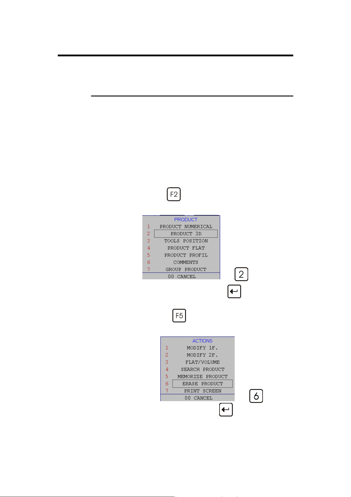
Call the PRODUCT 3D page.
Press the MENU
Select PRODUCT 3D. For that, enter the number indicated next to
the choice
or place the cursor on the choice and press
or click on the choice.
Press the ACTION
Choose ERASE PRODUCT. For that, enter the number indicated
function key.
: key ,
,
key.
next to the choice
or place the cursor on the choice and press
or click on the choice, and then CONFIRM.
PAGE 36 USER GUIDE PC/DNC 1200 2D&3D
: key ,
,
Page 45

Deletion of the
work memory
This operation erases only the data of the work memory. That means that the
product, which is possibly located in the work memory, is not lost if it has
been saved beforehand.
Introduce the
product data
Field: PRODUCT DATA
Click on the PRODUCT DATA field.
Introduce the THICKNESS and SIGMA values in the corresponding
fields (2.00 and 37).
Introduce MATERIAL: Click right to open the round robin list.
Introduce PUNCH and DIE according to the method mentioned
before (see Choice of Tools) in this document.
Click on QUIT to confirm the chosen values.
The program returns to the previous window. To continue, press the
key and choose MODIFY 1W or key
or MODIFY 2W or key
.
,
3D PROGRAMMING PAGE 37
Page 46

Difference between the two functions:
MODIFY 1W: Shows the product in plan mode (2D)
MODIFY 2W: Shows the product in plan mode and in axonometric mode
(3D).
Creation of the
base element
Current choice:
MODIFY 2W
Axonometric mode
Plan mode
• Click on
. The red rectangle (at right) is lighting up, attesting that
the function is active.
• The base rectangle appears in plan mode in the work window as well as
in axonometric mode. The diagram and the value table are adapted.
• Introduce the dimensions A and B. In our example: 150 and 200.
PAGE 38 USER GUIDE PC/DNC 1200 2D&3D
Page 47

Add a side
• Click on
. The red rectangle (at right) is lighting up, attesting that
the function is active.
• Click on the segment of the outline to which the side is to be added.
• Adjust the height of the side: value of the A field (45.00). The angle
value is 90° by default. The internal radius is already calculated.
Add a second side
The same function is still active.
• Click on the lower segment where the side is to be added.
• The value A has been memorized and is automatically attributed to the
new side.
3D PROGRAMMING PAGE 39
Page 48

Add a third side
The same function is still active.
• Click on the left segment where the side is to be added.
Add a fourth side
• The value A has been memorized and is automatically attributed to the
new side. Modify the A field with a new value: 40.00.
The same function is still active.
• Click on the left segment where the side is to be added.
• The value A has been memorized and is automatically attributed to the
new side. Modify the A field with a new value: 30.00, and modify the
angle value too: - 90.0°.
PAGE 40 USER GUIDE PC/DNC 1200 2D&3D
Page 49

Add the last side
Control the
construction
The same function is still active.
• Click on the right segment where the last side is to be added.
• The value A has been memorized and is automatically attributed to the
new side. Modify the A field with a new value: 20.00, and modify the
angle value too: - 135.0°.
The product is now finished.
Display the product in solidview.
• Press the
key and then key .
To come back to the construction mode:
• Press the key and then key .
3D PROGRAMMING PAGE 41
Page 50

This page has been left blank intentionally.
PAGE 42 USER GUIDE PC/DNC 1200 2D&3D
Page 51

M
EMORIZE OR SEARCH A PRODUCT
EMORIZE A PRODUCT
M
The memorizing of a product can be carried out from all pages containing the
PRODUCT field at the top of the screen.
Set the DNC in programming mode .
Place the cursor on the PRODUCT field and introduce the storage
number (1 to 89'999).
Menu ACTION, select MEMORIZE PRODUCT.
If the message EXISTS appears, this indicates that the N° selected is
already in use.
CANCEL and choose an other number
or
CONFIRM in order to erase the existing product.
List of products page If you wish to do this memorizing by having a global view of the existing
products:
Call the LIST OF PRODUCTS page by means of the MENU
key and by selecting the option LIST OF PRODUCTS of the menu.
In the DRAWING field, introduce a reference, if needed.
MEMORIZE OR SEARCH A PRODUCT PAGE 43
Page 52
If you want to memorize the product elsewhere than in the internal
memory, place the cursor on the INTERNAL field of PRODUCTS
AND GROUPS IN
and make your choice.
Place the cursor on the PRODUCT field and introduce the storage
number (1 to 89.999).
Press the ACTION key.
Select the MEMORIZE option.
The message SAVING... appears in the interactive field on the top
right-hand corner of the screen.
The number of the product recorded will then appear in the list.
See the following section and also Active peripherals and Product
management in the 2D Reference Manual.
EARCH A PRODUCT
S
Rapid method
or click right to cause the list to appear,
This method is valid only from the version W2 on.
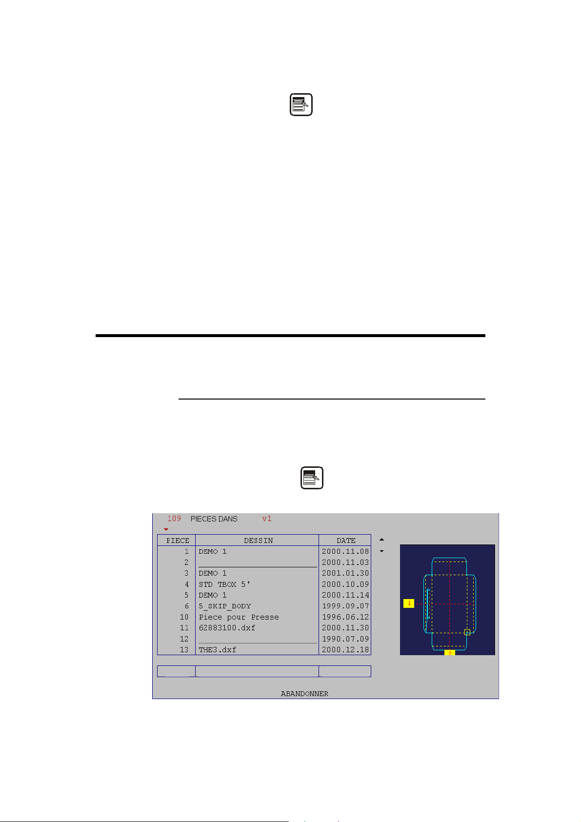
L
From any page displaying the PRODUCT field:
Position the cursor in the PRODUCT field.
Click right or press the
The following window is displayed:
key.
The products are initially listed in increasing order by product number.
To browse, place the cursor in the table and displace with the
PAGE 44 USER GUIDE PC/DNC 1200 2D&3D
Page 53

Sorting:
increasing / decreasing
To search a product:
To load the product: click or press the
or keys.
key.
To list in decreasing order:
place the cursor on the title of the column and click left
or press the
key.
The order is inversed (the red arrow is turned upwards ).
To sort by drawing name or date, proceed likewise in the titles of the
corresponding columns (DRAWING or DATE).
Position the cursor in the table in the desired column and introduce
there the product number, the drawing name or the searched date.
Your introduction is displayed on the last line (in white), and the
cursor positions on the first line of the table. The names are sorted in
increasing order, the first corresponding on the first line.
For more explanations, please refer to the 2D Reference Manual.
MEMORIZE OR SEARCH A PRODUCT PAGE 45
Page 54

Standard Method
If you want to search the product at a location other than the internal
memory, place the cursor on the INTERNAL field of PRODUCTS
AND GROUPS IN ...
and make your choice.
In the list, place the cursor on the number of the desired product and
press the key,
or
Place the cursor in the PRODUCT field, introduce the product
number and choose LOAD via the ACTION menu.
The product is now in the work memory (its number is displayed in
the PRODUCT field).
If you know the number of the product to be searched (provided that it is in
the active peripheral), you can search a product in all the pages displaying
the PRODUCT field on the top left of the screen.
To this end:
Introduce the product number in the PRODUCT field.
Choose SEARCH PRODUCT in the ACTION menu.
or click right to cause the list to appear,
PAGE 46 USER GUIDE PC/DNC 1200 2D&3D
Page 55
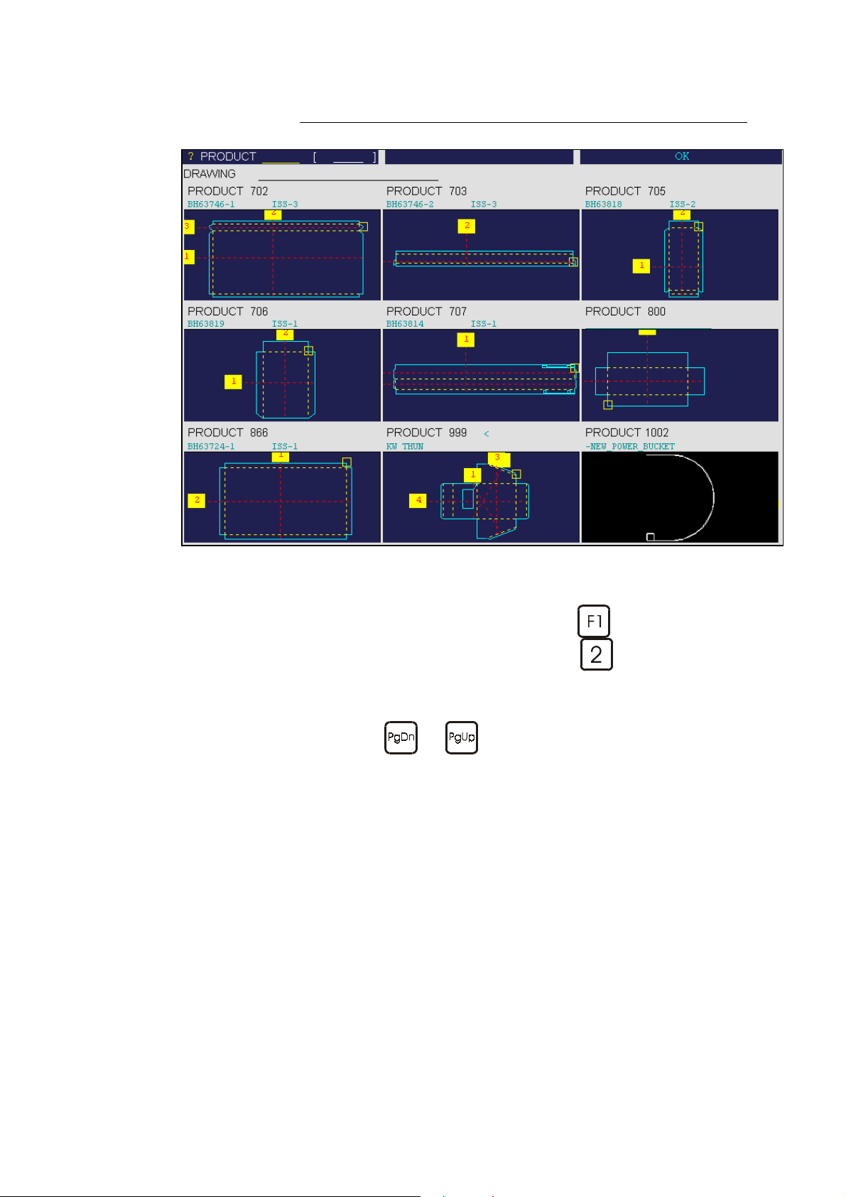
Graphic Method
Procedure:
Pass to the MENU page by means of the
List of graphical products page (key
The above window is displayed and allows you to make a search of
the products.
The functions
The product selection is identical to the standard mode.
and allow to scroll the list of graphical products.
key and call the
).
MEMORIZE OR SEARCH A PRODUCT PAGE 47
Page 56

RGANIZATION OF THE MEMORIES
O
This chapter is intended to furnish the essential elements to the DNC
functioning. For more complete information about the memories, please
consult the 2D Reference Manual.
The numerical control contains various memories. When the operator
programs a product or modifies the contents of a product, he is doing it in a
work memory, sometimes called buffer memory.
The work memory is non-volatile, that means, when you switch off the DNC,
the data of the current product remain stored in the memory until they are
replaced by an other product or deleted.
Floppy
INTERNAL
Work memory
or
buffer
Network
ENC
It is not necessary to save the product which has been programmed in the
work memory, if this one is of no more use once the product executed.
Generally, the product will be saved only if it has to be kept for future use.
A non-saved product in the work memory is recognizable, for the
PRODUCT field is empty.
The ENC is also provided with a memory which contains a copy of the
product located in the work memory. This copy is transferred to the ENC
when switching to semi-automatic or automatic mode.
An other memory, belonging to the DNC again, is the Floppy (disk).
Generally, the Floppy is used for the saving (backup) of important products,
the tools, and/or the machine parameters.
Therefore, the transfer page is used.
Although a product can be searched or stored directly in the Floppy, this
operation will be made very rarely because of the access speed.
Complementary memories can be those offered by a network access.
When normally configurated, the DNC always memorizes and searchs its
products in the INTERNAL memory. It is possible to attribute an other
memory by default to it (see Active Peripherals in the 2D Reference
Manual).
PAGE 48 USER GUIDE PC/DNC 1200 2D&3D
Page 57

P
ROTECTION OF THE ACCESS LEVELS
ENERAL INFORMATION
G
Depending on the version, the DNC 1200 can or can not be equipped with a
4positions physical key.
However the protection levels 0-1-2 and 3 still exist.
For the case where the physical key doesn't exist, the access is made by
password.
Thus, in this manual we will always speak of a (virtual) key position like
e.g.: "Key in position 3".
Levels There exist 4 access levels, 0 to 3.
0 = Programming prohibited.
1 = Creation, correction, modification, saving, deleting, transfer of one (or
more) product(s).
2 = Creation, correction, modification, saving, deleting, transfer of the tools.
3 = Programming, modification and transfer of the machine parameters.
Access These levels are reached by pressing the
Alt
+ ,
Remark: Release the numerical key before the Alt key.
The key position is displayed as a small pictograph at the right bottom of the
screen.
When passing to non-authorized level, a password modification will be
requested.
When the password has been introduced, you can "navigate" in the inferior
levels and equal to the authorized one without reintroducing the password.
The fact to pass on level 0 reinitializes the password request.
Users A number of different users are predefined. A user is not a physical person in
particular, but can be e.g. all the operators having the authorization to work
on the machine.
Each predefined user possesses his own password and a maximum level
which he can reach. See further under Table of users, access and passwords.
Password Certain users can modify their own password. For the others, the password
can only be changed by a user having a superior access.
Characteristics The password can be composed of alphanumerical characters if such a
keyboard is disposable. Otherwise only of numerical characters.
Alt
+ ,
Alt
+ or
Alt
+ keys.
Loss of the password In case of loss of the password, a user of a superior level has to reprogram
the password.
PROTECTION OF THE ACCESS LEVELS PAGE 49
Page 58

HE USERS
T
Table of users, access and passwords.
Level Names of
predefined
users
1
2
3
4 WSSUPER OK OK 3 817 Workshop supervisor
5 MACHMAN NO OK 3 Machine manufacturer's
6 MACHMAN0 OK OK 3 Responsible of the
A predefined user is just a role.
Many physical persons can have the same role. E.g., many physical operators can be a EUL1 (level 1).
After installing the machine it is advised to modify the password by default of level 4 (WSSUPER =
Workshop supervisor) and of level 3 (EUL3 = Operators with authorization level 3), because the
passwords are in this manual.
EUL1 NO NO
EUL2 NO NO
EUL3 NO NO
Changing of
the personal
password
Changing of
passwords of
the
subordinateds
Level
virtual key
1
2
3
Password
by default
111 Operators having the access
222 Operators having the access
333 Operators having the access
User generally attributed to:
authorization of level 1
authorization of level 2
authorization of level 3
Service technicians
technicians at the machine
manufacturer's
PAGE 50 USER GUIDE PC/DNC 1200 2D&3D
Page 59

CCESS BY PASSWORD
A
By starting the software, the virtual key is always positioned at 0.
When the operator selects one of the combinations
, the following message appears:
Level 1
Password
Enter the password.
Press
The authorized level is shown in the bottom right box in the screen.
Otherwise a message indicating that the user is not authorized is
displayed.
Once the authorization acquired, the operator can change the level among
those authorized to him without reappearing of a new password request.
For instance, a user with access on level 3 can navigate between levels 1, 2
and 3 without having to give his password again.
If level 0 is activated, the access on any other level will require to introduce
the password again.
This request also will appear when the user passes to a superior level (from 0
to 1, from 1 to 2, from 2 to 3, etc.) and he has no access authorization.
.
+ , or
or 2 or 3
according to
the keys
combination
Advice If you have accessed to level 3, access to level 0 after your intervention. This
will avoid to make undesired changings by inadvertence.
PROTECTION OF THE ACCESS LEVELS PAGE 51
Page 60

CCESS TO LEVELS SUPERIOR TO
A
Certain users can access to levels superior to 3, which enables them, among
other things, to modify the passwords.
In order to know the authorizations, see Table of users, access and
passwords.
3
Press the keys combination
The following message appears:
Changing key position
User WSSUPER
Password
Validate
Cancel
Password forgotten
Change password
Choose the desired user level (see table).
For that, place the cursor in the User field and press the
then make your choice and validate with
Place the cursor in the Password field and enter the password
corresponding to the requested level and validate with the
The DNC passes to level 1. The operator can "navigate" between
levels 1 and 3 without reintroducing his password.
If his access level enables him, he can call the procedure of password
modification (see next paragraph).
+ .
key,
.
key.
At the end of the intervention, don't forget to pass to level 0 in order
to leave the current level.
PAGE 52 USER GUIDE PC/DNC 1200 2D&3D
Page 61

HANGE PASSWORD
C
It is possible to modify the passwords attributed by default.
Certain users can do it for themselves, others not.
In order to know the authorizations, see Table of users, access and
passwords.
Procedure:
Press the keys combination
+
.
The following message appears:
Changing key position
User WSSUPER
Password
Validate
Cancel
Password forgotten
Change password
Log in as at least WSSUPER.
Introduce your password.
Click on Change password.
The following window appears:
Change password
User WSSUPER
New password
Confirm password
Validate
Cancel
Choose the user whose password is to be changed. For that, place the
cursor in the User field and press the
choice and validate with
.
key, then make your
Introduce the new password.
Type the new password in Confirm password.
Place the cursor on Validate and press
(or click on validate).
PROTECTION OF THE ACCESS LEVELS PAGE 53
Page 62

PASSWORD FORGOTTEN
If a user has lost / forgotten his password, ask to the responsible of the
machine.
If this password is definitively lost however, there are 2 possibilities: .
a) The user is not authorized to change his password himself.
2 solutions for this case:
- Ask the "superior" user to modify his password.
(See section Change Password).
- Use the method described below.
b) The user is authorized to change his password.
Proceed as described hereinafter.
Note:
If the forgotten password concerns levels 1, 2 or 3, ask the workshop
supervisor to modify the passwords of these levels according to the
procedure described in section Change Password.
Procedure:
Press the keys combination
+
.
The following message appears:
Changing key position
User WSSUPER
Password
Validate
Cancel
Password forgotten
Change password
Choose the user whose password is forgotten. For that, place the
cursor in the User field and press the
choice and validate with
.
key, then make your
Click on the choice Password forgotten.
PAGE 54 USER GUIDE PC/DNC 1200 2D&3D
Page 63

The following window appears:
Password forgotten
User WSSUPER
Auxiliary code Kl2398saf58sdf7
Please contact your supplier
Exit
The operator has to note the displayed auxiliary code and contact his
supplier. The latter disposes of a software enabling to generate a new
password.
In order to recover a forgotten password, proceed as follows:
Call the Password forgotten function.
Note the displayed auxiliary code.
Obtain the new password from the supplier by communicating him the
auxiliary code. You will be informed of the lost password.
PROTECTION OF THE ACCESS LEVELS PAGE 55
Page 64

This page has been left blank intentionally.
PAGE 56 USER GUIDE PC/DNC 1200 2D&3D
Page 65

B
RIEF OVERVIEW OF THE PAGES
Many complementary explications of these pages and/or the functions are
described in the 2D Reference Manual.
This manual is organized like a dictionary, with a table of contents and a very
detailed index for easy reference.
ENU PAGE
M
The MENU page
appears when the
MENU key
pressed.
To validate: place the
cursor on the required
option and press the
key, or type the
number next to the
choice.
is
IST OF PRODUCTS PAGE
L
This page allows to
extract the products
stored in the NC, in
numerical increasing
order.
BRIEF OVERVIEW OF THE PAGES PAGE 57
Page 66
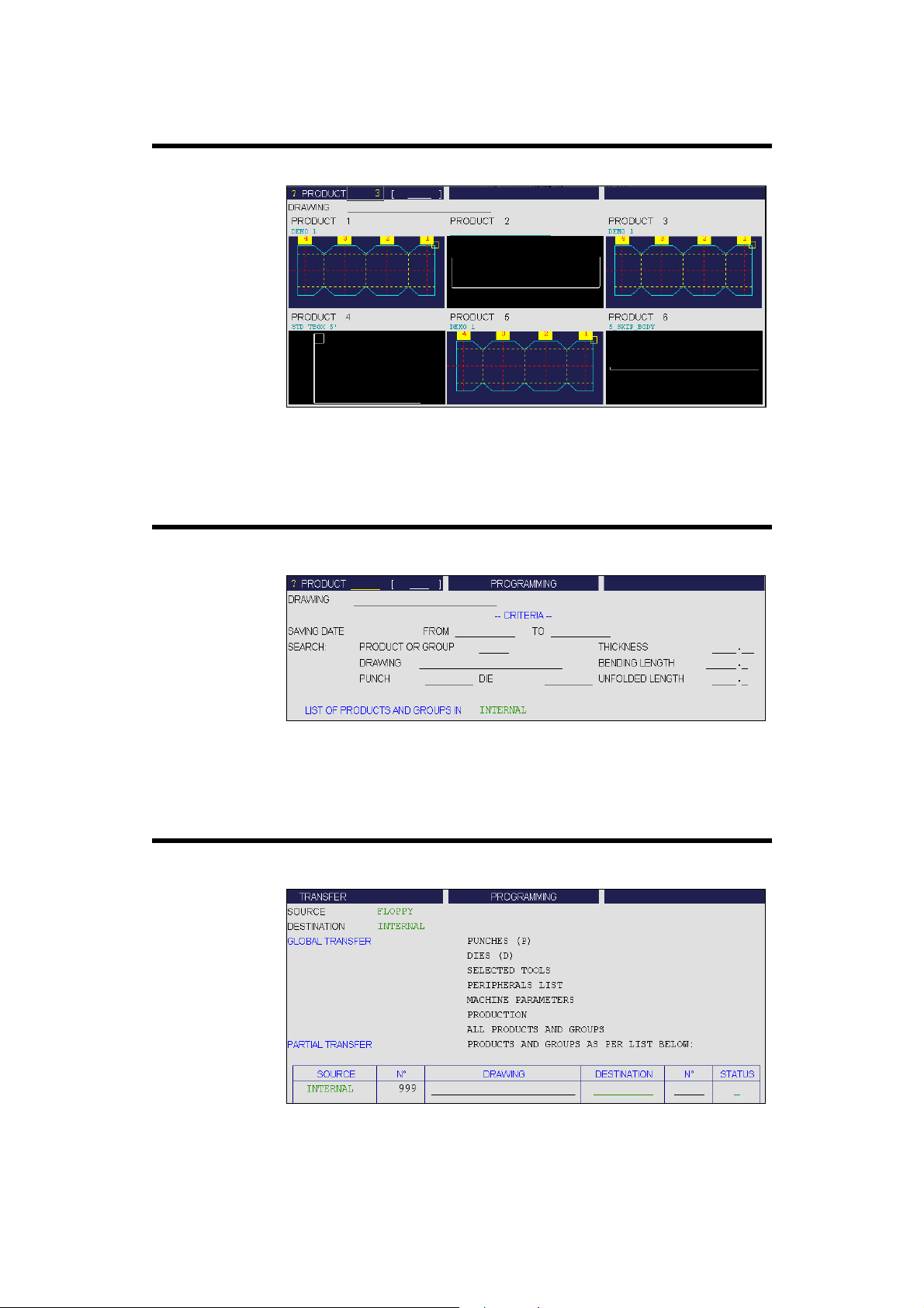
IST OF GRAPHICAL PRODUCTS PAGE
L
This page allows to
extract the products
stored in the NC, in
numerical increasing
order, and with the
graphic associated to
them.
RODUCT
P
This page allows to
search for different
products stored in the
numerical control
according to certain
criteria.
RANSFER PAGE
T
Allows to select and
command data
transfers from one
memory to another.
(Floppy, network, etc...)
RITERIA SEARCH PAGE
/ C
PAGE 58 USER GUIDE PC/DNC 1200 2D&3D
Page 67
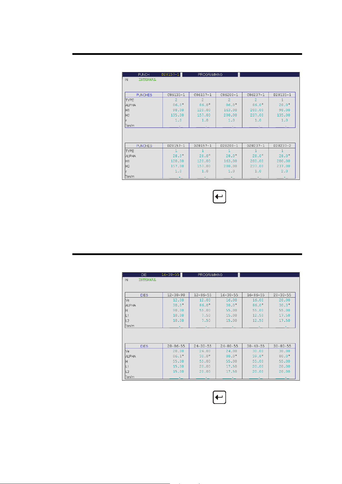
IST OF PUNCHES PAGE
L
This page gives a quick
glimpse at the main
parameters of the
punches stored in the
numerical control.
In this list, if you wish to see the complete description of the tool, just place
IST OF DIES PAGE
L
This page gives a quick
glimpse at the main
parameters of the dies
stored in the numerical
control.
the cursor on the tool's name and press
The PROGRAMMING PUNCHES page is then displayed.
, or click.
In this list, if you wish to see the complete description of the tool, just place
the cursor on the tool's name and press
The PROGRAMMING DIES page is then displayed.
BRIEF OVERVIEW OF THE PAGES PAGE 59
, or click.
Page 68

UNCH PROGRAMMING PAGE
P
Programming of all
punches is done from
this page.
All the dimensions
relative to the tool are
introduced here.
A drawing representing
the tool is displayed on
the right of the screen.
IE PROGRAMMING PAGE
D
Programming of all dies
is done from this page.
All the dimensions
relative to the tool are
introduced here.
A drawing representing
the tool is displayed on
the right of the screen.
PAGE 60 USER GUIDE PC/DNC 1200 2D&3D
Page 69

ELCOME PAGE
W
Main data for the
machine and the
numerical control.
The fields of green
colour are multiple
choice fields which can
be modified.
NITIALIZATION PAGE
I
This page is reserved
for the technical
maintenance of the
numerical control or the
machine.
This page allows to
clear the DNC data and
to modify the physical
indices of the machine.
The use of the front
panel key is necessary
to intervene on this
page.
BRIEF OVERVIEW OF THE PAGES PAGE 61
Page 70
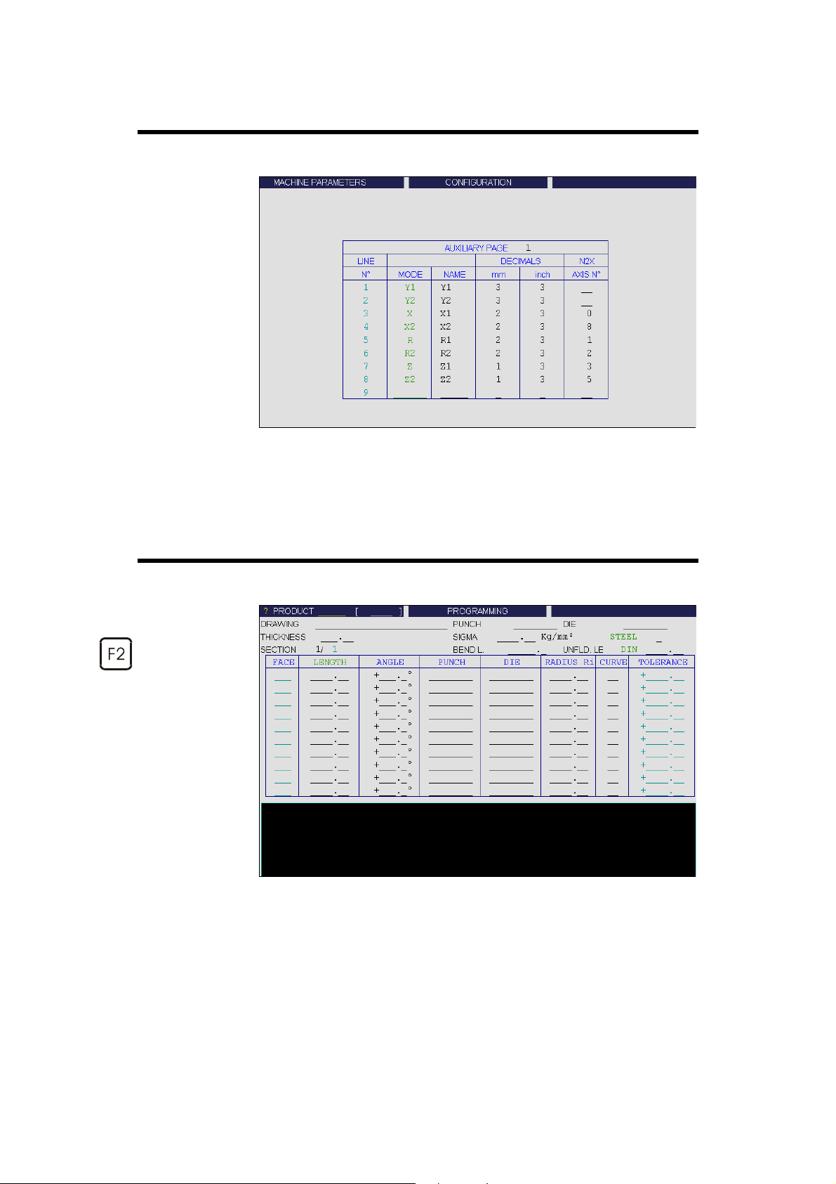
ACHINE PARAMETERS PAGE
M
This page is the first of
the pages which
constitute the list of all
the parameters which
condition the
functioning of the
numerical control.
This data can only be
modified with the front
panel key in position 3.
This data may be
modified only with the
aid of competent
technical support.
RODUCT NUM PAGE
P
This page appears
when the PRODUCT
key is pressed
and PRODUCT
NUMERICAL is
chosen.
This page allows to
construct and calculate
a product and to
visualize the profile of
the cut in real time.
PAGE 62 USER GUIDE PC/DNC 1200 2D&3D
Page 71
OOLS POSITION PAGE
T
This page appears
when the PRODUCT
key is pressed
and TOOLS POSITION
is chosen.
This page allows to
define several work
stations.
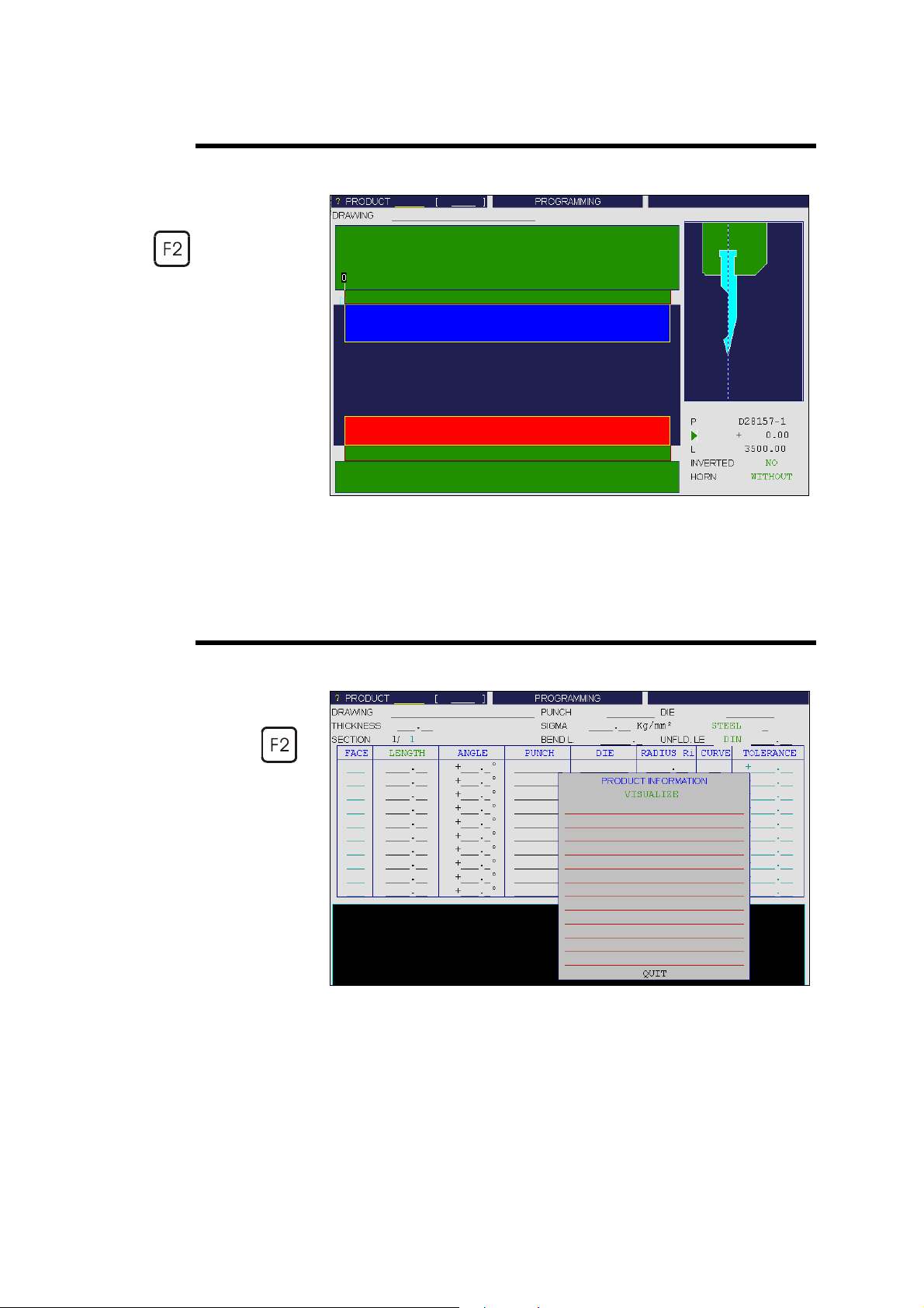
OMMENTS PAGE
C
This page appears
superimposed when
the PRODUCT
key is pressed and
COMMENTS is chosen.
This page allows to
complete the product
data with a series of
commentaries. These
commentaries are
programmed using a
PC software.
BRIEF OVERVIEW OF THE PAGES PAGE 63
Page 72

END NUMERICAL PAGE
B
This page appears
when the BEND
key is pressed and
BEND NUMERICAL
is chosen.
This page recapitulates
all the data for the
current sequence.
END
B
2D P
AGE
This page appears
when the BEND
key is pressed and
BEND 2D is chosen.
This page allows to
simulate the feasibility
of the product and to
correct the bending
order if necessary.
PAGE 64 USER GUIDE PC/DNC 1200 2D&3D
Page 73
END
B
This page appears
when the BEND
key is pressed and
BEND 3D is chosen.
This page allows to
simulate the feasibility
of the product and to
correct, if necessary,
the stop position as well
as the position of the
product relating to the
tools.
3D P
AGE
END FUNCTION PAGE
B
This page appears
when the BEND
key is pressed and
BEND FUNCTION is
chosen.
This page allows to
program any possible
auxiliary functions of
the machine.
BRIEF OVERVIEW OF THE PAGES PAGE 65
Page 74

END
B
This page appears
when the BEND
key is pressed and
BEND. TOOLS is
chosen.
This page allows to
modify the position and
the width of the tools
mounted on the
machine. Certain safety
factors can also be
modified here.
OOLS PAGE
. T
ORRECTIONS PAGE
C
This page appears
when the
CORRECTIONS key is
pressed and
CORRECTIONS is
chosen.
This page allows to
apply the corrections to
the different machine
axes as a function of
the results obtained
during bending.
PAGE 66 USER GUIDE PC/DNC 1200 2D&3D
Page 75

I
NSTALLATION OF THE
There are 4 figures to be distinguished:
1. Installation of PC 1200 Windows on a PC station.
2. Installation of PC 1200 Version DOS* or PC 900 (DOS) on a PC
station equipped with Windows.
3. Installation of the DNC 1200 Windows software.
4. Installation of the DNC 1200 DOS software.
* Only certain softwares.
PC 1200 for press brakes don't exist in DOS version.
PC P
ROTECTION KEY
The key must be equipped with at least the options 20, 25 to authorize
PC1200 to work.
Install the protection key on the parallel port LPT1 (printer).
PC/DNC 1200 S
OFTWARE
If a printer is connected to the computer (via the key) it must imperatively be
switched on.
L
Important: Do in no case connect the protection key to a serial port.
This may destroy the key.
Notes:
Always switch the PC or DNC off before connecting or
disconnecting a protection key !
The printer port of the PC or the DNC and/or the protection key might
become damaged if the key is connected or disconnected while the
power supply is switched on.
The protection key must be connected to the (first) printer port
(parallel port, LPT1) of the PC or the DNC.
Never connect the protection key to a serial port ("com port") !
This may cause damage to the protection key and/or the serial port of
the PC or the DNC.
If a printer is connected to the protection key, it must be switched on
for correct operation.
As a rule, a stack of multiple protection keys may be connected to the
printer port of the PC.
In some cases, the order of the keys may be important for correct
operation of the different software packages using these keys. In case
of problems, always start first to connect a single key (and do not
connect the printer) to determine if this solves the problem. If yes,
then try to add the other keys in different orders to determine the
correct order. If the problem cannot be solved for multiple keys,
consider to use a printer switch-box to switch between the different
protection keys.
INSTALLATION OF THE PC/DNC 1200 SOFTWARE PAGE 67
Page 76
For CYBELEC protection keys, only keys with different colours may
be stacked. Keys with the same colour may not be stacked.
This also means that a replacement of the protection key may be
necessary in case that an installed version of the software is updated
to a version with different options.
When starting, the software displays the WELCOME page.
At the bottom of this page you can read the serial number of the key, as well
as the available options.
If it happened that the key would not be recognized, the message ILLEGAL
CONFIGURATION appears, the serial number is empty and it is not
possible to go into other pages of the software.
In this case: leave the software, carry out each of the points below by always
restarting the software in order to know if the point has solved the problem.
- Verify that the key is really on the printer port LPT1.
- Let only the key alone switched on, without printer, without cable,
without another key or another periphery (for the rest of the tests).
- Install the Sentinel driver which is found in the CD directory under the
directory \Tools\Win_NT_2000\SproDrivers_NT359. For that,
execute the setup.exe which is found in this directory.
- For Windows NT or Windows 2000 or XP, you must have a Sentinel
Super Pro key which differentiates by its size (see photo). The other
keys (larger) are NOT recognized.
- "Under" Windows NT, 2000 or XP, it may be possible that additionally
the RAINPORT driver is to be installed which is on the CD of PC 1200
as well, in the directory \Tools\Win_NT_2000\Rainport.
- If all these attempts have not solved the problem:
Start the cybdng3.exe software which is found in the \Tools\Prot_key
directory. The carrying out of this last must return you the number of the
key as well as the available options.
- If there is no result, try on another PC of a different brand and if possible
with another OS (Win 95, Win 98). It happens that the port is not
compatible with the key.
- If the result is also negative on another PC, then the protection key may
have been damaged. This requires a replacement.
In a network configuration, the PC software can be installed on the server.
Note, however, that this is not recommended due to potential problems if
multiple users run the software at the same time. Also note that a protection
key is required for each PC running the software, and that the protection key
cannot be installed on the server.
PAGE 68 USER GUIDE PC/DNC 1200 2D&3D
Page 77

Depending on the configuration and options, the DNC also requires a
protection key. If the protection key is not found, the message illegal
configuration can be shown (and the DNC cannot be used in this case),
or one or more options of the DNC will not be available.
The protection key is not required for the installation of the software.
INIMUM CONFIGURATION
M
Pentium 100 Mhz
32 Mb Ram
Windows 95 / 98 / Me / NT4, 2000 , (XP reserved)
DNC: Windows 95 ORS2 (950B)
Mode 800x600
Colour 16 bits (65 536)
DNC: BIOS Setup configuration:
STANDARD SETUP Halt all but keyboard
OFTWARE SUPPORT
S
The software PC 1200 version Windows is supplied on CD-ROM.
Composition:
1 CD-ROM Cybelec SSAFFxx.
Also valid for the DNC.
1 configuration disk CONFIG 01 or higher.
Also valid for the DNC.
OFTWARE SUPPORT
S
The software DNC 1200 version Windows is supplied on CD-ROM.
Composition:
1 CD-ROM Cybelec SSAFFxx.
Also valid for the PC version.
1 configuration disk CONFIG 01 or higher.
Also valid for the PC version.
PC 1200 W
INDOWS
DNC 1200 W
INDOWS
1 network drivers disk.
An EPROM or the FLASH software for the ENC corresponding to the
version on CD-ROM.
The Windows license of the numerical control is at present supplied with a
CD-ROM including the license documents.
The CD-ROM and the license must always accompagny the numerical
INSTALLATION OF THE PC/DNC 1200 SOFTWARE PAGE 69
Page 78

control.
The License can be reduced to a simple Microsoft label sticked on the DNC.
See also the advice at the beginning of this User Guide.
OFTWARE SUPPORT
S
The software DNC 1200 version DOS is supplied on 3,5" floppy disks.
Composition:
1 installation disk SYSTEM S105 (PS) or S106 (PP)
1 software disk SSAFDxx
1 language disk
1 network drivers disk
An EPROM or the FLASH software for the ENC corresponding to the
version on CD-ROM.
The Windows license of the numerical control is at present supplied with
floppy disks and the license documents.
The floppy disks and the license must always accompagny the
numerical control.
The License can be reduced to a simple Microsoft label sticked on the
DNC.
DNC 1200 DOS
Don't try to install this software version on a PC.
For the PC, you need a PC1200 Windows version.
PAGE 70 USER GUIDE PC/DNC 1200 2D&3D
Page 79

I
NSTALLATION OF
Install de protection key.
Insert the CD-ROM in the CD reader and follow the instructions.
If the software asks you the question, choose Installation on PC
PC1200 W
(and not on DNC).
INDOWS
By default, the software sets up in a CYB/ directory and there in a
sub-directory under the name of the installed version.
This enables to have several different versions on the PC.
If the software asks you the question, introduce the CONFIG 03 disk
(or higher) and continue the installation.
If you have no diskette, click on NO, the software will then be
installed with the standard options.
INSTALLATION OF PC1200 WINDOWS PAGE 71
Page 80

Installation in an existing directory
If you wish to not keep your old version, but make an update in the same
directory as your old software, answer also by NO on the question "install
the CONFIG 03 diskette ?".
In this way the parameters of your old software will be kept, the
configuration, the parameters, the products and the paths.
Installation under Windows NT 2000 or XP
Attention: under these systems you must have the rights of an
ADMINISTRATOR to install the software.
Before or after the software installation, but before starting PC1200:
Install the Sentinel driver which is found in the CD directory under
the directory \Tools\Win_NT_2000\SproDrivers_NT359.
For that, execute the setup.exe which is found in this directory.
PAGE 72 USER GUIDE PC/DNC 1200 2D&3D
Page 81

I
NSTALLATION OF
The software PC 1200 DOS concern certain machines only, but in no case the
L
PC softwares for pressbrakes.
It is not possible to install on a PC the software DNC 1200 DOS supplied
with the DNC.
Insert the SYSTEM S105 disk in drive A.
Menu Windows Execute / Start.
Introduce A:\install and then type ENTER.
Installation under Windows NT, 2000 or XP
Attention: under these systems you must have the rights of an
Before or after the software installation, but before starting PC1200:
PC1200 / PC900 DOS
Follow the instructions.
ADMINISTRATOR to install the software.
VERSION
Install the driver Sentinel 3.59 which is found in the CD directory
under the directory \Tools\Win_NT_2000\SproDrivers_NT359.
For that, execute the setup.exe which is found in this directory.
Test. If the software still doesn't recognize the key, install the driver
RAINPORT 2.0 which is found on the CD of PC1200 in the directory
\Tools\Win_NT_2000\Rainport.
If you don't have this CD at hand, you can download these drivers at the
following addresses:
http://www.rainbow.com/tech/downloads.html
and
http://www.cybelec.ch/utils/rainport.htm
Known problems:
Under all these versions the mouse movements are greatly slowed
(which is not the case with Windows 95, 98 and Me).
No solution has been found up to this day.
Under Windows 2000 and XP the fact to use the mouse risks to
"crash" the software.
No solution has been found up to this day.
Under Windows 2000 and XP, only the key Super Pro is recognized
(see section PC Protection key above).
for the Sentinel drivers.
Visit, however, regularly our web site where you will be informed about our
innovations.
INSTALLATION OF PC1200/PC900 DOS VERSION PAGE 73
Page 82

NSTALLATION OF
I
It is presumed that Windows is already installed in the DNC.
Install an external keyboard.
Switch the DNC on.
Let the software do its loading completely.
Go on level 3.
Leave the software.
At this moment, Windows is available.
Insert the CD-ROM in the CD drive and follow the instructions.
If the software asks you the question, choose Installation on DNC.
If the software asks you the question, introduce the CONFIG 03 disk
(or higher) and continue the installation.
If you don't have the diskette, click on NO.
Leave Windows.
Switch the numerical control off.
Change the software of the ENC in concordance with the version
newly installed on the DNC.
DNC W
INDOWS
IF THE KEYBOARD OF THE DNC DOESN'T WORK:
Leave Windows.
Switch the DNC off.
Install an external keyboard.
Switch the DNC on.
During the boot, press the Del key.
In the BIOS setup under the STANDARD SETUP page, make sure
that the option Halt on is on Halt all but keyboard.
Save and leave the BIOS setup.
PAGE 74 USER GUIDE PC/DNC 1200 2D&3D
Page 83

NSTALLATION OF
I
It is presumed that DOS and a previous version of the the software is already
installed in the DNC.
Switch the numerical control off.
Insert the SOFTWARE diskette.
Start the DNC.
Follow the instructions.
Insert the LANGUAGES diskette when required.
Remove the diskette at the end of the installation.
Switch the numerical control off.
Change the software of the ENC in concordance with the version
DNC DOS
The software installs itself by keeping the previous configuration and
data.
newly installed on the DNC.
Installation with new options or reformatting
This version enables to reinstall the DNC completely and to possibly format
the Flash disk of the numerical control.
Switch the numerical control off.
Insert the SYSTEM S105 diskette.
Start the DNC.
Follow the instructions.
If you choose to format, all the data contained in the DNC will be lost.
Insert the LANGUAGES diskette when required.
Remove the diskette at the end of the installation.
Switch the numerical control off.
Change the software of the ENC in concordance with the version
newly installed on the DNC.
INSTALLATION OF PC1200/PC900 DOS VERSION PAGE 75
Page 84

IF THE KEYBOARD OF THE DNC DOESN'T WORK:
Leave Windows.
Switch the DNC off.
Install an external keyboard.
Switch the DNC on.
During the boot, press the Del key.
In the BIOS setup under the STANDARD SETUP page, make sure
that the option Halt on is on Halt all but keyboard.
Save and leave the BIOS setup.
PAGE 76 USER GUIDE PC/DNC 1200 2D&3D
Page 85

A
Access
by password, 49, 51
Protection of the access levels, 49
to levels superior to 3, 52
Access level, 49
INDEX
doesn't work, 74, 76
L
L-alpha method, 11
License
Documents, 70
Windows, 70
Add a side, 39
B
Bend
copy, 30
Bending range
modify, 22
search, 22
C
Construction
control, 41
Copyright & License agreement, 5
D
Die adjustment, 15
Driver
Rainport, 68
Sentinel, 68
F
function key, 8
I
Icons, 35
Illegal configuration, 67
Installation, 67
List of products, 43
Locking of the software, 73
M
Memorize a product, 43
Memory
Buffer memory, 48
Floppy disk, 48
internal, 48
Network, 48
Work memory, 48
Mouse, 7
slow, 73
O
Operating system, 5
P
Password, 49
change, 53
forgotten, 54
Loss, 49
lost, 54
Programming
3D, 35
direct, 25
Section 1, 18
Section 2, 19
Protection key, 67, 71
Punch adjustment, 13
K
Key
virtual, 49
Keyboard
INDEX PAGE 77
S
Safety instructions, 5
Search a product
Graphic method, 47
Page 86

Rapid method, 44
Standard method, 46
Sentinel Super Pro, 68
T
Tools
Choice, 28
Tracksensor, 7
U
Users
Table, 50
W
Warranty, III
Windows NT, 2000 or XP, 67, 72, 73
Work memory
clear, 12, 26, 36
PAGE 78 USER GUIDE PC/DNC 1200 2D&3D
 Loading...