

Page 1

ModEva
PC 1200 3D
3D Reference Manual
Page 2

Page 3

27 February 2003 V. 1.1
CONTENTS
INTRODUCTION..............................................................................................................................3
Safety, Copyright & License agreement..............................................................................3
About this manual 3
REFERENCE MANUAL...................................................................................................................5
Abandon ..............................................................................................................................5
Bend: forced bend...............................................................................................................5
Bend: with / without .............................................................................................................5
Changing the bending orde r................................................................................................5
Changing the legs ...............................................................................................................6
Changing the stops .............................................................................................................6
Choice of Tools ....................................................................... ............................................7
Click.....................................................................................................................................7
Collinear ..............................................................................................................................7
Colours: Signification........................... ........................................... .....................................8
Constructing a product in 3D...............................................................................................8
Cursor..................................................................................................................................8
Deleting a bend ...................................................................................................................9
Deleting all the bends of a section 9
Deleting all the bends of a prod uct 10
Deleting the work memory...................................................................................................10
Dimensions..........................................................................................................................10
PRODUCT 3D page 10
Dimensioning Table.............................................................................................................12
Field.....................................................................................................................................12
Function keys ................................................. ........................................... ..........................12
Function keys: Definitions ...................................................................................................13
MENU 13
PRODUCT 13
BEND 13
CORRECTIONS 13
ACTIONS 14
EXECUTE 14
L(DIN), L'(CUT) ............................... ........................................... .........................................15
Measuring............................................................................................................................15
Modifying bend data............................................................................................................17
Outline.................................................................................................................................17
Page: BEND 3D ........................... .................................................................................. .....18
Page : PRODUCT 3D..........................................................................................................19
3D Visualization page 19
1 Window Modification page 20
2 Windows Modification page 20
Pictographs: Designation of the pictographs ...................................................................... 2 1
Pictographs: Definition of the 3 D pictographs... ..................................................................22
4 views 22
MODEVAREF3D_EN.DOC CONTENTS PAGE 1
Page 4

Bend: added 23
Bend: choice 24
Changing pictographs 25
Eraser 26
Forced bends 27
Information 27
Internal cut 28
Leg 31
Move 35
Notch 35
Origin 36
Punch 37
Rectangle 42
Rotation: horizontal 45
Rotation 3 axes 45
Stop 46
Stretch 47
Trapezium 49
Vertex 50
Wire frame 51
Zoom 51
Positioning a sheet under a punch..................................................................................... 53
Positioning the tools in the tool holder................................................................................ 53
Product data ....................................................................................................................... 56
Segment ............................................................................................................................. 56
Selecting a view.................................................................................................................. 58
Simulation........................................................................................................................... 58
Complete simulation 58
Simulation with programmed bends 59
Simulation of the bend 59
Starting construction of a 3D product................................................................................. 60
Stretching (lengthening a product) ..................................................................................... 61
Vertex ................................................................................................................................. 62
Windows .............................................................................................................................62
Zooming.............................................................................................................................. 63
INDEX.............................................................................................................................................. 65
PAGE 2 3D REFERENCE MANUAL MODEVA
Page 5

INTRODUCTION
SAFETY, COPYRIGHT & LICENSE AGREEMENT
Please consult the safety instructions, copyright and license agreement on the
first pages of the manual.
ABOUT THIS MANUAL
This manual is destined to bring a precise aid for specific 3D construction
problems.
It is complementary to the ModEva User Guide manual.
The User Guide manual gives the procedure to be followed for creating a
3D product.
This manual is organized like a dictionary.
That is the items are in alphabetical order. If a subject is treated in a chapter
other than the one you are consulting you will find a cross-reference of the
new subject.
The index situated at the end of the manual will help the search for
information.
This manual only treats the 3D graphics relative to the ModEva
software.
The topics concerning other parts of the software are dealt with in the
ModEva 2D Reference manual.
A-C PAGE 3
Page 6

This page has been left blank intentionally.
PAGE 4 3D REFERENCE MANUAL MODEVA
Page 7

REFERENCE MANUAL
ABANDON
Field situated in the dimensioning table of the PRODUCT 3D pages.
Function
If the operation is not performed the right way round or as desired, click on
ABANDON in the dimensioning window and start again.
Attention, it is impossible if you click outsi de the dimensioning window.
► ABANDON only appears while it is still possible to annul the work being
done.
BEND: FORCED BEND
See Pictographs: Forced bends.
: cancels the current operation.
BEND: WITH / WITHOUT
See Pictographs: Rectangle and Pictographs: Trapezium
CHANGING THE BENDING ORDER
Bend 3D page
To change the bending order already established:
"Position" the product on the first bend to be modified using the
or
If you are satisfied with the bend, pass to the next one with
Click on
see also Pictographs: Bend: choice.
keys.
.
.
A-C PAGE 5
Page 8

CHANGING THE LEGS
The ModEva software determines the bending order and the legs as a
function of the simulation criteria (BEND 3D, MULTI SIM, CRITERIA
SIM). It is possible to modify the leg or the stop on a product already
simulated.
Bend 3D page
See Pictographs: Leg.
CHANGING THE STOPS
Function:
Allows to choose another stop than the one proposed by the simulation (as
long as another stop is available).
Bend 3D page
Procedure:
Position the cursor on the STOP field.
Click left repeatedly to scroll the different stops.
or
Click right to display the list of stops
Select the stop required.
Leave the STOP field.
The software displays the new position and recalculates all the axes as a
function of the new stop.
PAGE 6 3D REFERENCE MANUAL MODEVA
Page 9

CHOICE OF TOOLS
In PAGE mode: PRODUCT 3D or MODIFY 1W or MODIFY 2W, the user
can at any time modify the choice of the tools.
Procedure
:
Click on the PRODUCT DATA field by positioning the cursor with
the help of the mouse or the cursor keys. See Cursor.
Or position the cursor in the PRODUCT DATA field and press the
The following dialogue window is displayed:
Position the cursor on the field of your choice (PUNCH or DIE).
The following of the operations is described in details in the ModEva
User Guide.
or key.
CLICK
COLLINEAR
Action of pressing the left or right buttons on the mouse or tracksensor.
In this manual it should be understood that:
Mouse means a mouse for a PC
or a tracksensor for a DNC.
Click left press the left mouse button.
Click right press the right mouse button.
Click left/right press simultaneously the left and right mouse
buttons.
Collinear bends refers to forced bends.
They are in the flat pattern o n the same line and are realized in a single
operation.
See Pictographs: Forced bends.
Collinear segments: segments aligned end to end.
A-C PAGE 7
Page 10
COLOURS: SIGNIFICATION
The colours represent different categories, that is:
Blue Used for titles and headnotes.
Black Fixed information.
White Information displayed by the system which cannot be
modified by the user.
Black frame Field accessible to the user to designate data or to
introduce or modify information.
Green Field accessible to the user to choose between several
proposed options (scrolling field). The passage from one
operation to another is done by repeated clicks.
CONSTRUCTING A PRODUCT IN 3D
See Starting construction of a 3D product, PRODUCT 3D page, and
Pictographs.
You can also refer to the User Guide Manual.
CURSOR
The cursor is a graphic marker which allows you to localize the mouse
action. When it is positioned on a modifiable field, the whole field is
surrounded with a black frame.
To move the cursor from field to field, use the
keys.
, , ,
PAGE 8 3D REFERENCE MANUAL MODEVA
Page 11

DELETING A BEND
It is understood by deleting a bend:
Annulling the position of the bend in the bending order, to reposition it
elsewhere.
It must not be confused with deleting a bend, operation which effectively
removes a bend from the product. See Pictograph: Eraser.
Bend 3D page
Position the cursor on the BEND field.
Introduce the Nb of the bend to be deleted.
or
Press
Press
DELETE BEND and validate with click or
The bending order and the leg number of the bend are deleted, as well as all
the relative axis data’s (BEND NUM page).
or up to the Nb of the bend to be deleted.
and then or position the cursor on
key.
DELETING ALL THE BENDS OF A SECTION
Bend 3D page
Position the cursor on the SECTION field.
Introduce the Nb of the section concerned.
or
Press
or up to the Nb of the section concerned.
Press
ERASE SECTION and validate with click or
The bending order and the leg number of all the bends of the section
are deleted.
D-F PAGE 9
and then key or position the cursor on
key.
Page 12

DELETING ALL THE BENDS OF A PRODUCT
Bend 3D page
Proceed as for a section, but for every section of the product.
DELETING THE WORK MEMORY
This operation is to be carried out before creating a new product. It empties
the work memory of all the previous data.
Procedure
Press and then key or position the cursor on CLEAR
DIMENSIONS
PRODUCT 3D PAGE
There are 2 types of dimensioning, L(DIN) and L'(CUT).
The selection is made on the top right hand corner of the PRODUCT 3D
construction pages by clicking on the L(DIN) or L'(CUT) field.
L(DIN)
L(DIN) indicates that the construction dim ensions are the external values of
the finished product.
PRODUCT and CONFIRM with
.
PAGE 10 3D REFERENCE MANUAL MODEVA
Page 13
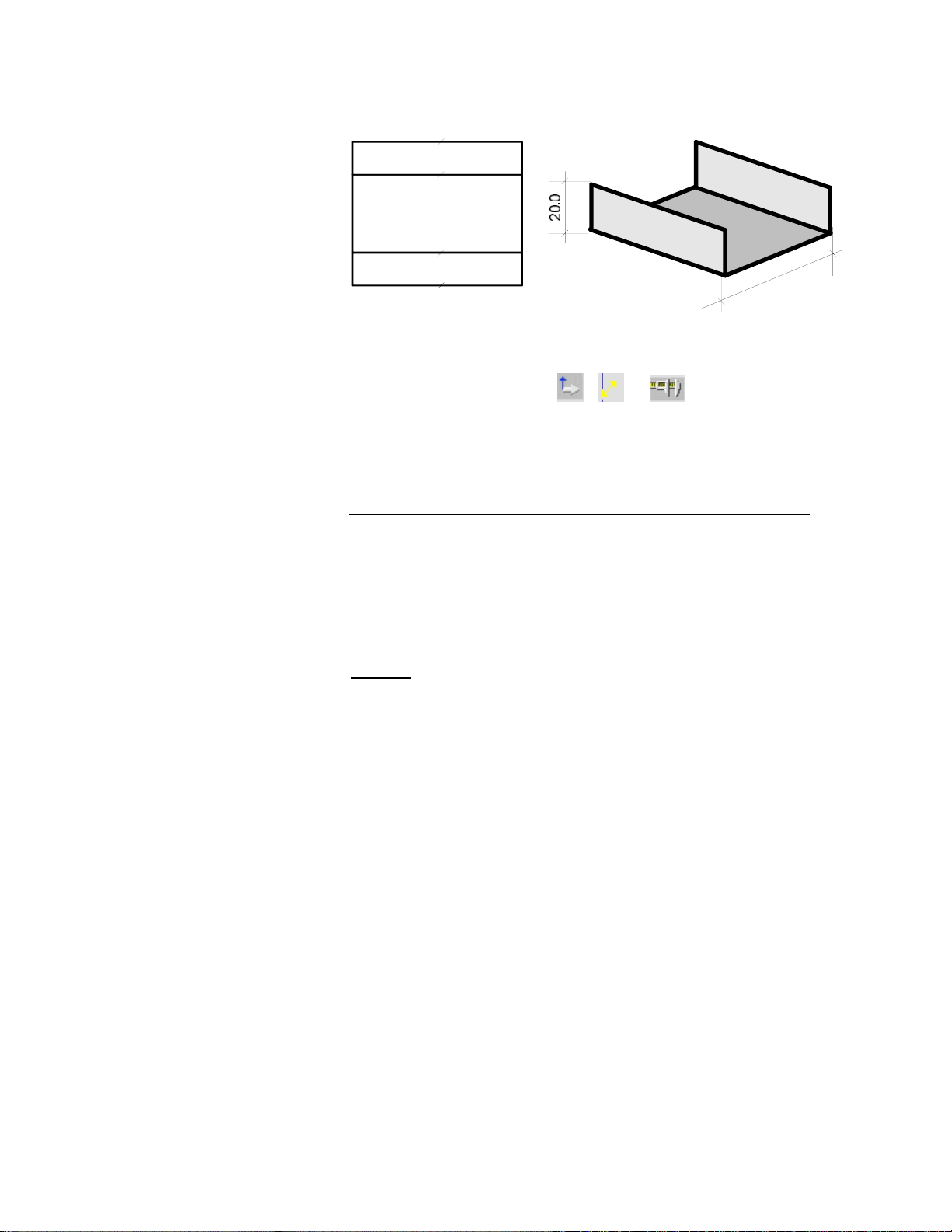
Example:
20.0
80.0
20.0
The construction drawing is a sketch. The measurements are not the real
values of the outline.
80.0
The measurements made using the
, or symbols are
indicative construction values in external dimensions.
See Measuring.
L'(CUT)
L'(CUT) indicates that the construction dimensions are the real values of the
punched or cut product.
An operator possessing a "punching machine" drawing can program the
product with the values indicated.
The positioning of the bends must be done with the dimensions
corresponding to those used with the old "bending to a line" method.
Attention
Changing from L(DIN) to L'(CUT) or vice versa, does NOT convert the
dimensions from one mode to the other.
The L(DIN) or L'(CUT) field only indicates to the software which
dimensioning method is used for the introducti on of the data.
:
D-F PAGE 11
Page 14
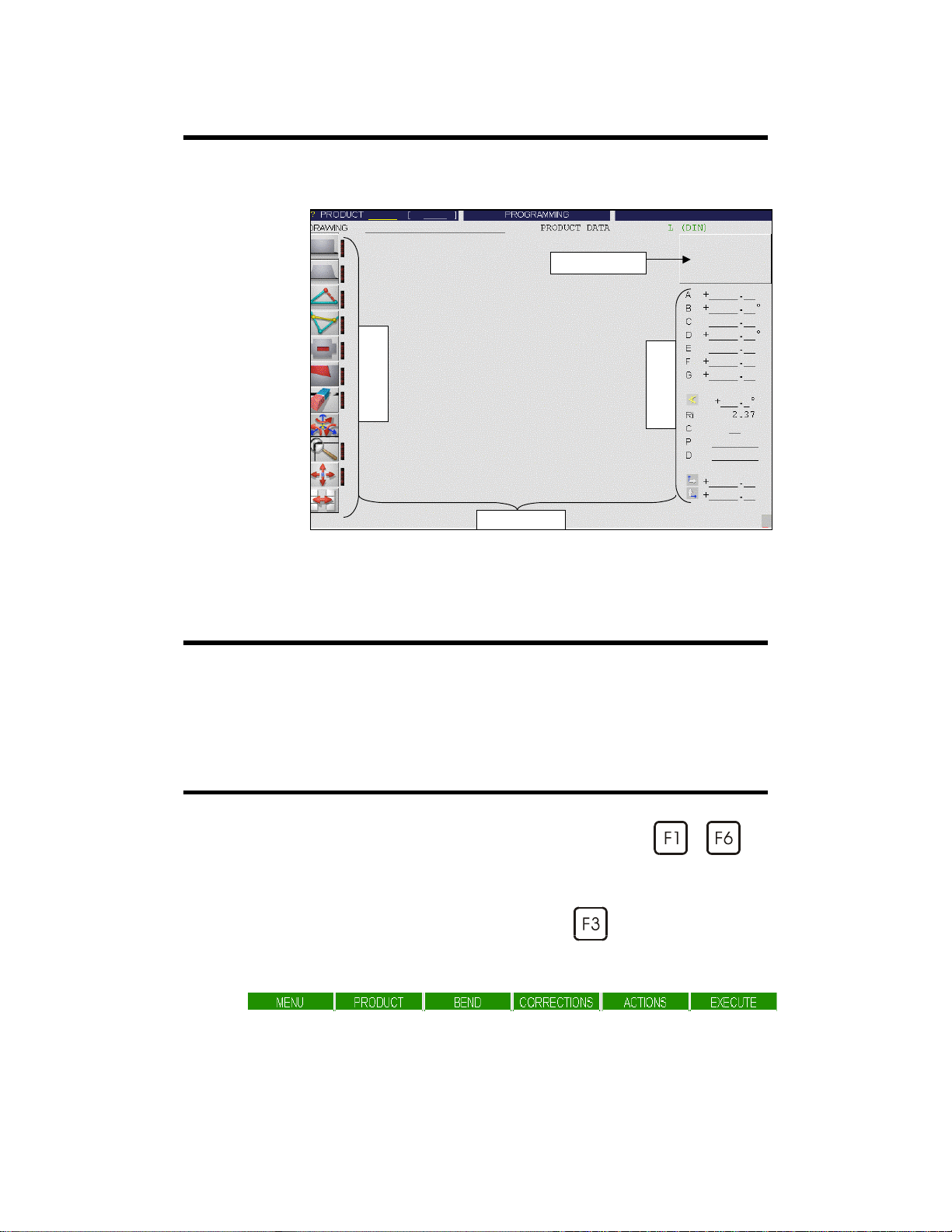
DIMENSIONING TABLE
The dimensioning table allows defining the dim ensions of the objects
brought to the construction using the pictographs.
Window’s diagram
FIELD
Zone accessible using the cursor, for entering or selecting data by clicking
successively.
FUNCTION KEYS
The function keys are those on the keyboard marked from to .
Pictograph’s column
Working wind ow
Dimensioning table
Each time it is necessary to press a function key, we will mention, for
example: press BEND 3D.
Example: BEND 3D invites you to press on
multichoice window in which you will find the BEND 3D function.
F1 F2 F3 F4 F5 F6
PAGE 12 3D REFERENCE MANUAL MODEVA
(BEND) and then opens a
Page 15

FUNCTION KEYS: DEFINITIONS
In this paragraph, the following function keys will be defined:
to .
MENU
Allows to reach, from any page, directly the MENU page of the program.
PRODUCT LIST, PUNCH LIST, PRODUCT SEARCH, MACHINE
PARAMETERS, etc.
PRODUCT
Allows to reach, from any page, directly the PRODUCT page of the
program.
PRODUCT NUM, PRODUCT 3D, TOOLS POSITION, PRODUCT
PLAN, etc.
BEND
Allows to reach, from any page, directly the BEND page of the program.
BEND NUM, BEND 2D, BEND 3D, BEND PICTURE, etc.
CORRECTIONS
D-F PAGE 13
Allows to reach, from any page, directly the CORRECTIONS page of the
program.
CORRECTIONS, TOOLS BEND.
Page 16

ACTIONS
Allows to reach, from any page, directly the ACTIONS page of the program,
which will appear in a different way, according to the page in which the
operator is.
Example:
Page PRODUCT 3D: MODIFY 1W, MODIFY 2W, MEMORIZE
PRODUCT, ERASE PRODUCT, etc.
Page BEND 3D: SEARCH BENDING ORDER, SIMULATE BEND,
DELETE SECTION, INSERT BEND, SIMULATION CRITERIA, etc.
EXECUTE
Function
Generally, this key can be used as a validation function, equivalent to a click
or the
In the BEND NUM, PRODUCT NUM and BEND 3D pages, if the cursor
is on the PRODUCT field, it is used to make a search. By entering de
number of the product, this one is loaded in the work memory.
In the PRODUCT NUM page, if outside of the PRODUCT field, it carries
out the calculation mode.
:
key.
PAGE 14 3D REFERENCE MANUAL MODEVA
Page 17

L(DIN), L'(CUT)
See Dimensions.
MEASURING
At the bottom of the dimensioning table, PRODUCT 3D pages (MODIFY
1W and MODIFY 2W), you will find the symbols to be used for measuring
the dimensions of the product.
See also Dimensions.
By clicking on the symbol, its appearance changes depending on the type of
measurement (3 possible selections).
The 3 types of symbols:
Cartesian co-ordinates (in the text = ).
Polar co-ordinates (in the text = ).
"Callipers" type of measurement.
The co-ordinate measurements are always made between the origin of
the product (displayed by a small square) and the origin of the active
violet segment (displayed by a small violet circle).
The calliper mode of measurement is made from face to point, as callipers
would.
To change the place of the active segment, press the
To change the origin of the product, click on the
click on the required vertex.
It is possible to make several successive measurements at different points by
leaving the
You can then simply use the graphic cursor to position the origin of the
product (
) and use the or keys to displace the current segment.
pictograph active.
or keys.
pictograph and then
L-P 15
Page 18

Cartesian co-ordinates
By default the method is applied.
This method gives in the relevant fields the co-ordinates of the origi n (b) of
the active segment (violet).
Ex:
b
a
+
+
140.00
70.00
Polar co-ordinates
Ex.
b
c
a
The length is that measured between a and b. The angle displayed is c.
+
156.52
26.57°
PAGE 16 3D REFERENCE MANUAL MODEVA
Page 19

Callipers
Ex.
c
a
The calliper measurements are made perpendicularly between the line, which
is drawn at the origin of the product (a) and the origin of the active
segment (b).
The measurement displayed is c.
MODIFYING BEND DATA
b
+
120.00
OUTLINE
If you wish to modify an angle, the internal radius of a product bend already
programmed or if you wish to use another tool for this bend.
Select the PRODUCT 3D page.
Select MODIFY 1W or MODIFY 2W.
Click on the bend to be modified.
Change the values
Leave the field to validate the new values.
Perimeter of the product, formed by the segments.
See Segment.
Ri, CR, P or D in the dimensioning table.
L-P 17
Page 20
PAGE: BEND 3D
On this page it is possible to simu late and display the feasib ili ty of the
product in 3 dimensions.
The pictographs and fields allow to:
Generate a proposition of a set of bends (see Simulation).
Display the product in its tools and detect collisions.
(see Pictographs: 4 views and Pictographs: Rotation: horizontal).
Realize modifications to the bending order.
(see Changing the bending order).
Modify the choice and the position of the stops.
(see Changing the legs and Changing the stops).
Choose the workstation (see Pictographs: Punch).
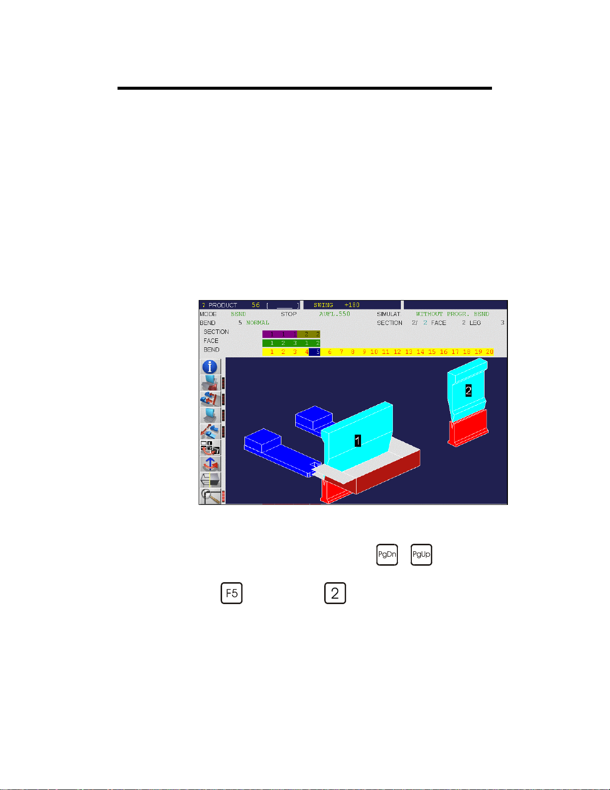
BEND 3D page
To display the bends one after another, use the
To see the finished bend:
Press
PAGE 18 3D REFERENCE MANUAL MODEVA
(ACTION) and then (SIMULATE BEND).
or keys.
Page 21

PAGE : PRODUCT 3D
The PRODUCT 3D page allows controlling the construction and the
appearance of a product in 3 dimensions.
It includes 2 sub-pages used for the construction of the product.
3D VISUALIZATION PAGE
The PRODUCT 3D page
is used by the operator to
examine a finished
product.
ZOOM,
3 AXES ROTATION
and
IMAGE
DISPLACEMENT
functions are available.
These sub-pages are called by the function keys
MODIFY 1W and
, then to MODIFY 2W.
, then to
MODIFY 1W allows you to gain access to th e 1
(modification/creation), below.
L-P 19
st
construction page
Page 22

MODIFY 1W
st
1
3D creation page
with the construction
pictographs.
1 WINDOW MODIFICATION PAGE
2 WINDOWS MODIFICATION PAGE
MODIFY 2W
Opens 2 windows. One
flat view and one 3D.
To change over the
windows, click on the
small window or activate
PLAN/VOLUME.
, then .
The construction of the product can be made using 2 dimensioning modes.
See Dimensions.
PAGE 20 3D REFERENCE MANUAL MODEVA
Page 23

PICTOGRAPHS: DESIGNATION OF THE PICTOGRAPHS
The names defined below are those which you will find throughout the
manual and during discussions with CYBELEC engineers and technicians.
leg
stop
internal cut
notch
wire frame
eraser
change pictograph
displace
punch
rectangle
horizontal rotation
3 axes rotation
vertex
stretch
trapezium
zoom
information
4 views
origin
bend : added
bend : choice
forced bend
P-PICTOGRAPHS PAGE 21
Page 24

PICTOGRAPHS: DEFINITION OF THE 3D
PICTOGRAPHS
A pictograph is active when a red mark is visible on its right edge.
Example:
Pictograph active:
4 VIEWS
BEND 3D page
Function
Switches 1 view display to 4 views display and vice-versa.
The 4 views display allows to select rapidly the one, which seems the most
appropriate for continuing the work.
Procedure
Pictograph non-active:
:
:
Click on the pictograph.
4 views appear on the screen.
Click right on the window, which most closely resembles the view
you wish to examine.
4 new views are displayed.
Each Click right on the selected window displays 4 new views.
Usually, after 3 to 5 clicks, the required view appears.
Click left on the window you wish to see on full screen and the
system switches to 1 view mode.
PAGE 22 3D REFERENCE MANUAL MODEVA
Page 25

BEND: ADDED
PRODUCT 3D / MODIFY 1W and MODIFY 2W page
Function
:
Allows adding a bend between two segments of the outline.
Procedure
:
Click on the 1
Click on the 2
st
segment (it becomes violet).
nd
segment (it becomes violet (A) and the 1st segment
selected (B) becomes green).
Enter the values in the dimensioning window.
st
A by default is 1/2 the length of the 1
B by default is 1/2 the length of the 2
C by default is the other 1/2 length of the 1
D by default is the other 1/2 length of the 2
segment clicked.
nd
segment clicked.
st
segment clicked.
nd
segment clicked.
E is the angle between the segment C and the line of the bend.
F is the angle between the segment D and the line of the bend.
The sum of the segments A and C are equivalent to their construction
segment.
The sum of the segments B and D are equivalent to thei r construction
segment.
In this example, the left segment o f the triangle has been select ed first,
followed by the right segment. The bend is automatically placed in the
middle of the two segments.
P-PICTOGRAPHS PAGE 23
Page 26

The bend has been placed elsewhere by modifying the data in the
dimensioning table.
BEND: CHOICE
BEND 3D page
Function
This pictograph allows to define, using the mouse, the bend to be realized in
the given sequence.
Procedure
Example:
:
:
Click on the pictograph. The punch disappears.
Click on the bend to be made.
The LEG pictograph is automatically validated, to allow the
immediate selection of the leg. Attention not to leave the graphical
window, otherwise the LEG pictograph is deactivated.
PAGE 24 3D REFERENCE MANUAL MODEVA
Page 27

The LEG
punch has disappeared.
Click on the new leg.
Depending on the case, to select the new leg, it is necessary to rotate the
product, or to delete the display of the tools and / or the machine.
pictograph is automatically activated and the
CHANGING PICTOGRAPHS
PRODUCT 3D / MODIFY 1W et MODIFY 2W page
Function
Allows to change the set of pictographs (toggle function).
That is, allows to pass from 1
P-PICTOGRAPHS PAGE 25
:
st
to 2nd set etc.
Page 28

ERASER
PRODUCT 3D / MODIFY 1W and MODIFY 2W page
Function
Allows to delete a vertex or a bend.
DELETING a vertex or a bend
It should be understood by "deleting a vertex" that the junction between two
segments of the outline are deleted and replaced by a single segment.
Example:
:
Click on the pictograph.
Position the cursor on the vertex or bend to be deleted.
Click.
Remark:
If deleting a vertex brings a bend to the edge of the outline the message THE
BEND FIRST appears in the interactive field .
The relevant bend must first be deleted.
Depending on the operations realized, it is possible that 2 (co-linear)
segments appear to be only one, when one is in the extension of the other or
if they overlap.
The sketch on the left below demonstrates this situation.
Use the
same colour will move from segment to segment. It is then possible to
transform these two segments into a single segment, by clicking on the
connection in the middle.
Pg Dn
or the key. The magenta segment with a circle of the
PAGE 26 3D REFERENCE MANUAL MODEVA
Page 29

FORCED BENDS
PRODUCT 3D / MODIFY 1W and MODIFY 2W page
Function
Allows defining the forced bends.
Forced bends are those bends which can be realized in one bending
operation.
Because of this they must necessarily "in the fl attened out product" be on a
bending line (collinear).
:
Procedure
See also Pictographs: Punch.
:
Click on this pictograph.
Click on the 1
Click on the 2
Each bend selected (forced) is displayed in red.
To leave and validate, click on a spot away from the relevant zone.
st
bend.
nd
bend, etc.
"Separate" the forced bends already defined
Same procedure as for forcing. By clicking on a bend already forced, it
"separates" from the bends still forced. Its colour returns to yellow as for a
solitary bend.
INFORMATION
BEND 3D page
Function
Allows the user to choose the elements he wishes to display:
Beam – Table – Tools.
Procedure
P-PICTOGRAPHS PAGE 27
:
:
Click on the pictograph, the DRAW window opens.
Position the cursor on the field to be modified.
One click, switches the YES ⇔ NO field.
Click LEAVE to validate the data and close the window.
Page 30

INTERNAL CUT
PRODUCT 3D / MODIFY 1W and MODIFY 2W page
Function
Allows to create a cut inside the product.
Procedure
:
:
Click on this pictograph.
Click on the segment where the peduncle is to be placed.
By default the peduncle is placed at 90° to the construction segment.
If the cut is not placed at the required spot , click on ABANDON in
the dimensioning window and start again (see Abandon).
Enter the values in the dimensioning window.
A and B are used to adjust the starting position of the peduncle on the
construction segment.
(The segment on which the cut has been "inserted" has been automatically
divided into two segments A and B whose sum is equivalent to the former
segment).
C is the distance between the construction segment and the hole (the segment
C is called the peduncle).
D and E define the size of the hole.
F is the angle between the segment C and the hole.
G is the angle between the segment C and the segment B.
The peduncle is an element of internal construction.
Physically, it is composed of 2 adjacent segments (separated by 0.05 mm)
connecting the construction segment to the internal cut.
Remark: The internal cut is placed in the face on which is located the
construction segment and face (see below).
PAGE 28 3D REFERENCE MANUAL MODEVA
Page 31

Example of an internal cut on the external face.
Example of an internal cut with different angl es (F and G values).
Example of an internal cut on the internal face.
To realize a cut as shown in the example above, a certain procedure must be
followed.
P-PICTOGRAPHS PAGE 29
Page 32

Procedure
General rule: The internal cut must be added immediately after the creation
of the face which "receives" the cut.
In the above example, the cut must be created immediately after the creation
of the base face.
:
The segments must then be attached to the periphe ry.
On the cut’s construction segment, the automatic adaptat ion of the face only
"covers" the semi-segment.
PAGE 30 3D REFERENCE MANUAL MODEVA
Page 33

The C value of the Rectangle diagram must thus be modified. This value
should be negative and correspond to the value of the second segment to be
covered to obtain the above result.
LEG
Bend 3D page
Allows to select another leg than the one displayed in the current sequence
The software automatically positions the axes and the stop fingers separated
at 80% (or another value defined by the machine parameters) onto the new
leg segment.
It immediately displays the new sheet metal position.
Procedure
If the segment chosen is not valid, or if the cursor is badly placed, the
POSITION BADLY DEFINED message is displayed.
Attention to not leave the graphical window, otherwis e the pictograph is
deactivated.
Remarks:
This function allows to easily and effectively choose the new legs.
A leg defined automatically by the simulation or by the method described
above is called a nominal leg.
In the case where this function does not allow you to put the stops at the
required place, use the
In the case where the leg segment is not parallel to the bending line, the
software introduces position corrections on the correction page.
For more correction details, see 2D Reference Manual.
:
Click on this pictograph.
Click on the required leg; the stop positions itself on the new leg.
The LEG field is modified with the number of the new leg.
pictograph.
P-PICTOGRAPHS PAGE 31
Page 34

Example before the procedure:
Procedure
:
Click on this pictograph: the red rectangle is lighting up.
Click on the required leg; the stop positions itself on the new leg.
The LEG field is modified with the number of the new leg.
Example after the procedure:
PAGE 32 3D REFERENCE MANUAL MODEVA
Page 35

Another example before the procedure:
Carry out the same procedure as previously described.
Example after the procedure:
P-PICTOGRAPHS PAGE 33
Page 36

MOVE
PRODUCT 3D (DISPLAY) page
PRODUCT 3D / MODIFY 1W and MODIFY 2W page
Function
Allows to displace the image.
Procedure
:
:
Click on the pictograph.
Click with the cursor on a virtual reference point which is to be
displaced.
Move the mouse to the place where the virtual reference point should
be located (a continuous line is traced) and click to validate.
The display is up-dated and shows the product in its new position.
A second click deactivates the pictograph.
The pictograph previously selected remains active.
NOTCH
PRODUCT 3D / MODIFY 1W and MODIFY 2W page
Function
Allows to add a notch of a variable form to the vertex of a face.
Procedure
:
:
Click on the pictograph.
Click on the vertex of the product outline.
PAGE 34 3D REFERENCE MANUAL MODEVA
Page 37

Enter the values in the dimensioning window.
If the notch is not placed at the required spot, click on ABANDON in
the dimensioning window and start again (see Abandon).
A is the length of the 1
B is the length of the 2
C is the length of the 3
D is the length of the 4
st
segment starting from the vertex.
nd
segment starting from the vertex.
rd
segment t.
th
segment.
E is the angle between the segments A and D.
F is the angle between the segments C and D.
Result of the notch in the above example.
ORIGIN
PRODUCT 3D / MODIFY 1W and MODIFY 2W page
Function
Allows to define a different point of origin on a product already realized.
This function is used, for example, to make a measurement on the product
(see Measuring).
:
P-PICTOGRAPHS PAGE 35
Page 38

Procedure
:
Click on this pictograph. The pictograph is activated.
Click on the chosen vertex.
Click on the
disactivated.
Remark:
As long as the pictograph is active, it is possible to modify the place of the
origin.
pictograph to validate. The pictograph is
PUNCH
BEND 3D page
Function
Allows to define the station to be used to realize a given bend (if the choice
exists).
Procedure
:
:
Click on this pictograph, a window opens.
Click on the drawing of the punch to be used.
The sheet metal positions itself under the new punch.
Click on LEAVE or outside the working window to validate the data
and close the window.
or
Alternatively:
Click on this pictograph, the same window opens.
Modify the value of the SHEET METAL fi eld.
The sheet metal positions itself at the new value and the dimensioning
of the Z axes follow the new positioning of the sheet.
Click on LEAVE or outside the working window to validate the data
and close the window.
or
to pass to the next bend.
to pass to the next bend.
PAGE 36 3D REFERENCE MANUAL MODEVA
Page 39

Example:
Click on
Click on the drawing of the punch with number 2.
Click on the LEAVE field of the window.
The product centres itself under the chosen punch (2).
, a window opens.
P-PICTOGRAPHS PAGE 37
Page 40

Options of sheet metal positioning
Positioning under a punch
It may be necessary to position the sheet metal, instead of centred, aligned to
the left or the right of the punch.
st
1
click 2nd click 3rd click
th
4
click etc.
By clicking repeatedly on the punch, the product positions itself:
in the centre, left edge, right edge, centre, left edge etc.
Click on the LEAVE field of the window to validate the position, or
pass to the next bend.
Forced bends under 2 punches
In the case where 2 forced bends must be realized under 2 distinct stations
(punches), there is a way which allows to position automatically the sheet
metal between these 2 punches.
Take the following case:
The bends A and B are defined as forced bends.
See Pictographs: Forced bends.
The 2 stations 1 and 2 are defined on the POS.TOOLS page.
A
B
to
If you click between the 2 punches, the software positions the space between
the 2 forced bends centrally in relation to the space between the 2 punches
(following figure).
To select the space between the 2 punches, it may be necessary to modify the
3D view in order to see the whole face. See the following remark.
PAGE 38 3D REFERENCE MANUAL MODEVA
Page 41

2
1
Take another example:
In the following example, the bends a, b, c and d are also forced bends.
The bends a and b are to be bent under one station, the bends c and d under
another.
There are 3 intervals named here x, y and z.
ab c
d
xy z
The first click between 2 punches will position the space between forced
bends which is best adapted to the space available between the punches (in
the example: y).
st
figure following where y is centred.
See 1
The other following clicks position alternatively the other spaces.
P-PICTOGRAPHS PAGE 39
Page 42

st
click
1
y is centred between the two
punches
nd
click
2
x is centred between the two
punches
rd
3
click
z is centred between the two
punches
th
4
click
y is centred again
etc.
2
1
2
1
2
1
2
1
:
Remark
The "sensitive" zone of a punch is defined by a rectangle (
you and completely surrounds the punch (see following figure).
This is why if you have difficulty in selecting the space (
punches, it is recommended to display a front view for this operation.
PAGE 40 3D REFERENCE MANUAL MODEVA
a) which faces
b) between 2
Page 43

a
b
RECTANGLE
PRODUCT 3D / MODIFY 1W and MODIFY 2W page
Function
Allows to attach a rectangular face to any segment of the outline.
This face will automatically adapt its length to that of the segment selected.
In this last case, the last values programmed are used by default.
Depending on the state of the symbol
(see Option with or without bend and in this paragraph.).
Procedure
:
, a bend will be realized or not
:
Click on the pictograph.
Click on the receiving segment of the product outline.
If the face does not position itself at the required place, click on
ABANDON in the dimensioning window and start again (see
Abandon).
Enter the values in the dimensioning window.
A is the height of the face.
B is automatically adapted to the construction segment
C and D are the distances between the extremities of the construction
segment and the extremities of the new face.
P-PICTOGRAPHS PAGE 41
Page 44

Add a flap
Add another flap
Click on
. The pictograph is activated.
Click on the segment of the outline to which the side is to be added
(upper segment).
Adjust the height of the side (A) in the value table. The bending angle
is by default 90°.
Click on the lower segment where the side is to be added.
The value A has been memorized and is automatically attributed to the
new side.
Remark:
The values introduced in the dimensioning table are automatically reported
for the other faces which will be added afterwards.
PAGE 42 3D REFERENCE MANUAL MODEVA
Page 45

Option with or without bend
The symbol in the dimensioning wi ndow, can activate the option with /
without bend, by repeated clicks.
The appearance of the dimensioning window is modified in consequence.
This option allows to simplify the construction of the product.
For example to obtain the outline without bend below:
2 possibilities:
1. by suppression of a surface.
2. by addition of a surface.
Fig 1
Suppression of a surface.
Draw a rectangle (1).
Add a face (2) without bend,
with a negative height (A).
Suppress the upper segment of
Fig 2
Addition of surfaces
Draw a rectangle (1).
Add a face (2) without bend.
Add another face (3) without
bend.
the rectangle (2).
P-PICTOGRAPHS PAGE 43
Page 46

ROTATION: HORIZONTAL
Bend 3D page
Function
Allows to pivot horizontally the displayed product.
Procedure
Remark: The rotation is made around the axis, at the centre of the
:
:
Click left: rotation to the left.
Click right: rotation to the right.
current bend, with a predetermined angle (not modifiable).
ROTATION 3 AXES
PRODUCT 3D (VISUALIZE) page
PRODUCT 3D / MODIFY 1W and MODIFY 2W page
Function
Allows to rotate the product around one of the selected axes.
This pictograph behaves like three pictographs, one for each axis
Procedure
Click on the arrow of the axis to be activated.
Each click makes a predetermined angular rotation.
:
:
Click left: rotation to the left.
Click right: rotation to the right.
PAGE 44 3D REFERENCE MANUAL MODEVA
Page 47

STOP
BEND 3D page
Function
Allows to adjust the position of the stops in the zone close to the nominal
leg.
Two possibilities are offered:
a) By programming numerically the Z1, Z2 position in the window ad
b) By clicking with the mouse on the graphical product.
Procedure
Alternatively:
:
hoc.
:
Click on the pictograph. A window opens at the top of the screen.
Modify numerically the position of the Z1 and Z2 stops.
Click on LEAVE to validate the data and close the window.
First click on the stop to be displaced. The stop changes its colour.
Second click on the spot where the stop is to be placed.
Click on LEAVE to validate the data and close the window.
P-PICTOGRAPHS PAGE 45
Page 48

STRETCH
PRODUCT 3D, MODIFY 1W and MODIFY 2W page
Function
:
Allows the simultaneous lengthening of 2 segments of the outline.
This function is especially useful for creating products which are similar but
which have certain dimensions that are different (for example modules for
drawers, lids etc.).
2 dimensioning diagrams are available.
Click on the diagram to make them appear one after the other.
Procedure
:
Click on the pictograph.
Click on the first segment to be modified (becomes magenta).
Click on the 2
and the 1
nd
segment. It becomes magenta in its turn (segment A)
st
segment selected (B) becomes green.
Enter the values in the dimensioning window.
If the result is not as desired, click on ABANDON in the
dimensioning window and start again (see Abandon).
Example:
Original product.
PAGE 46 3D REFERENCE MANUAL MODEVA
Page 49

Select the first segment to be modified: left segment.
nd
Select the 2
segment to be modified: right segment .
Modify the dimensioning table. The product contai ns the new dimensions.
P-PICTOGRAPHS PAGE 47
Page 50

TRAPEZIUM
PRODUCT 3D (MODIFY 1W and MODIFY 2W) page
Function
Allows to attach a trapez o idal face to any segment of the ou tline.
Procedure
2 dimensioning diagrams are available.
Click on the diagram to make them appear one after the other.
:
:
Click on the pictograph.
Click on the segment of the outline where the trapezium is to be
attached.
Enter the desired values in the dimensioning window.
A is the height of the trapezium.
B is the base opposite the construction segment.
C and D are the distances between the extremities of the construction
segment which supports the trapezium and the extremities of the trapezium.
E and F are the angles in relation to the base of the construction segment.
A is the height of the trapezium.
B is the base opposite the construction segment.
C and D are the segments connecting the two bases.
E and F are their projections.
Option with or without bend
The symbol in the dimensioning window can activate the option with /
without bend, by repeated clicks. The appearance of the dimensioning
window is modified in consequence.
PAGE 48 3D REFERENCE MANUAL MODEVA
Page 51

VERTEX
PRODUCT 3D page
Function
Allows to add a vertex to the outline (to divide a segment of the outline in
two).
Procedure
2 dimensioning diagrams are available.
Click on the diagram to make them appear one after the other.
The sum of F and G will automatically be adjusted to the length of the
construction segment.
A is the height of the triangle formed by the vertex added.
B is the angle between the segment C and its projection F on the
construction segment.
C and E are the distances between the added vertex and the two vertexes of
the construction segment.
D is the angle between the segment E and its projection G on the
construction segment.
:
:
Click on the pictograph.
Click on the segment to be modified.
If the face does not position itself at the required place, click on
ABANDON in the dimensioning window and start again (see
Abandon).
Enter the values in the dimensioning window.
The large base of the triangle formed by the added vertex will be adjusted
automatically to the length of the construction segment.
A is the distance between the added vertex and the vertex of the construction
segment (that is the length of the new segment)
B is the angle between the new segment A and the previous segment
C is the extension of the previous segment.
D is the height of the triangle formed by the segments A and C.
Remark: This procedure does not add a bend between the two
extremities of the new segments.
P-PICTOGRAPHS PAGE 49
Page 52

WIRE FRAME
PRODUCT 3D (DISPLAY) page
BEND 3D page
Function
Switches the display from "Wire frame" mode to "hidden faces" (surface
drawing) mode and vice versa.
:
Procedure
Position the cursor on this pictograph and validate with click or
Sometimes, in the case of insufficient memory, the wire frame mode is
forced automatically.
:
.
ZOOM
PRODUCT 3D page
BEND 3D page
Function
Allows to enlarge a portion of the screen with the help of a selection
window.
Procedure
:
:
Click on the pictograph. It becomes active.
Position the cursor in order to determine the departing position of the
window, then click.
Position the cursor in order to determine the final point of the
window.
A selection window appears. Click on the required position. The
selected window is displayed on the screen.
Click on the pictograph again. The latter is disactivated.
Click on the pictograph. It becomes active and the program optimizes
the display. All the elements become visible.
Remark
: As long as the pictograph is activated, it is possible to make
another zoom with the help of the selection window.
PAGE 50 3D REFERENCE MANUAL MODEVA
Page 53

PRODUCT 3D Page
Position the product at the required display angle.
Enlarge the part required.
BEND 3D Page
not active The display adapts continuously to show the
centre of interest (that is the area immediately
surrounding the bend).
active Allows to select the part to be enlarged.
The display does not change when passing from
one sequence to another.
On the BEND 3D page, this allows for example
to always have the whole of the machine on the
screen when several working posts are used.
P-PICTOGRAPHS PAGE 51
Page 54

POSITIONING A SHEET UNDER A PUNCH
On the BEND 3D page, it is possible to define the position of the sheet metal
and the position of the Z axes.
See Pictographs: Punch.
POSITIONING THE TOOLS IN THE TOOL HOLDER
The access to this page is made by means of the (PRODUCT) and
Tool page before
modification action
then the
It allows to define the position of the tools used by this product.
This data are stored with the product.
Procedure
Click on the punch grip.
(POS TOOLS) keys.
:
A punch with a length equivalent to the maximum size of the press is
displayed.
PAGE 52 3D REFERENCE MANUAL MODEVA
Page 55

st
punch
1
Cursor on P, click right or key.
Refer to the Instructions manual (Choice of tools).
nd
2
punch
Cursor on
, introduces the left punch position.
Cursor on L, introduces the tool length.
To create the next punch:
Click on the tool support to the left or right of the existing punch (or use the
or keys).
P-Z PAGE 53
Page 56

nd
2
punch
Cursor on P, choose the punch.
Definition of the die
Cursor on
, introduce the left tool position.
Cursor on L, introduce the tool length.
Click on the die grip.
A die with a length equivalent to the maximum size of the press is
displayed.
Cursor on
, introduce the left tool position.
Cursor on L, introduce the tool length.
To create the following dies, proceed as for the punches.
Remark
:
If a product has been created on the PRODUCT NUM page and the tools
have also been defined on that PRODUCT NUM page, they appear when
you gain access to the TOOLS POSITION page.
As their positions have not been defined, they are placed arbitrarily. It is up
to you to redefine then according to your needs.
PAGE 54 3D REFERENCE MANUAL MODEVA
Page 57

PRODUCT DATA
Introduce the product
data
To execute a simulation, a calculation etc. the software needs the product
data.
It is thus convenient to start the construction of the product by introducing
these data.
Click on the PRODUCT DATA field.
For more details on the procedure, please refer to the section Starting
construction of a 3D product.
SEGMENT
A segment is a part of the product outline which joins two apexes.
It is a straight whose length is defined when introducing the data.
Each segment can be selected.
A segment can be:
Split in two (see Pictographs: Vertex).
Modified, lengthened (see Pictographs:Stretch).
Used as a support for the construction of other elements (see
Pictographs: Rectangle / Trapezium / Internal cut).
P-Z PAGE 55
Page 58

Current segment
The current segment is displayed in violet with a circle at its end.
The current segment circle (v iolet) is called origin of the current
segment (
It must not be confused with the origin (yellow) of the product (
To " pass" from one segment to another, you can either click on the relevant
) or current vertex.
).
segment or use the
or keys.
Construction segment
The construction segment is a "reception" segment on which is added a
rectangular face, a trapezium, a vertex, the peduncle of an internal cut and /
or the extremity of a bend.
Superimposed segments
Depending on the construction operations, it is possible that several segments
are superimposed. Sometimes this situation is necessary, sometimes it is the
result of bad manipulations.
Superimposed segments cannot be activated (vi olet) using the mouse, but
only by using the
Deleting a superimposed segment
or keys.
Use the or keys to activate the required segment then proceed to
delete it as described in Pictographs: Eraser by clicking on the acti ve
segment.
Constructing a superimposed segment
Use the or keys to activate the required segment then select the
relevant construction pictograph and proceed normally by clicking on the
active segment.
PAGE 56 3D REFERENCE MANUAL MODEVA
Page 59

Collinear segments
The collinear segments are segments which are an extension of each other
and give the impression of being a single segment. This situation comes
from, as in the case of superimposed segments, successive modifications.
These segments are usually useless.
To detect collinear segments, simply scroll the current segment along the
whole length of the outline.
The situation below shows two collinear segments.
To delete the superfluous segment, refer to Pictographs: Eraser.
SELECTING A VIEW
See Pictographs: 4 views.
SIMULATION
Simulation is software task which, depending on predefined criteria, searches
for a sequence (set) of bends for the programmed product .
Of course, the operator remains free to modify the proposed bending order.
To reach the simulation criteria page press the
(BEND 3D), then
CRITERIA) keys.
COMPLETE SIMULATION
This operation redoes the whole simulation and does not take into account
any solutions already programmed. It is used when different solutions are
sought by modifying the simulation criteria.
Procedure
(BEND), then
(ACTIONS) and then (SIMULATION
:
Select the BEND 3D page
Select the SIMULAT field on WITHOUT PROG BEND and leave
the cursor on it.
Press
The software presents a simulated solution under the first punch. To place the
product under other stations, see Pictographs: Punch.
P-Z PAGE 57
, then (SEARCH BENDING ORDER).
Page 60

SIMULATION WITH PROGRAMMED BENDS
This option allows to impose the order of certain bends and to let the
software "find" a solution for the remaining bends.
By selecting WITH PROGRAMMED BENDS, the software does not
modify the order of the bends having a defined face and leg.
Procedure
The software presents a solution taking into account the bends already
programmed. To place the product under other stations, see Pictographs:
Punch.
:
Delete all the bends.
(see Deleting a bend).
Define the programmed bends.
(see Changing the bending order and Pictographs: Bend: choice).
Select the SIMULAT field on WITH PROGRAMMED BENDS and
leave the cursor on it.
Press
, then (SEARCH BENDING ORDER).
SIMULATION OF THE BEND
After having defined the order of the bends manually or by simulation, the
software displays the position of the product before bending.
If you wish to see the appearance after bending, simply press the function
key
and then (SIMULATE BEND).
Example
Press
PAGE 58 3D REFERENCE MANUAL MODEVA
:
and then to see the bend being made.
Page 61

STARTING CONSTRUCTION OF A 3D PRODUCT
An example of product creation is described in the User Guide manual.
Refer to it for more information.
Procedure
:
Introduce the product
data
Select PRODUCT 3D. (
Select MODIFY 1W or MODIFY 2W (
Delete the memory.
See Deleting the work memory.
Enter the product data.
Click on the PRODUCT DATA field.
The above window appears.
Introduce the THICKNESS and SIGMA in the corresponding fields.
and then ).
, then or ).
Introduce MATERIAL: Click right or
list or click successively on the field (green) to scroll one after another
the names on the list.
P-Z PAGE 59
to open the round robin
Page 62

Introduce PUNCH and DIE in one of the following ways:
Create the base
element
1. Click right or
Click on the chosen name.
2. Introduce the name directly into the relevant field.
Click QUIT to confirm the chosen values.
The program returns to the previous window. To continue, press
choose MODIFY 1W or key
displays the list of names.
. The following window opens:
and
Click on
The base rectangle appears in the work window.
Introduce the dimensions A and B.
A
The diagram allows to define the base rectangle.
The A and B values must be adjusted.
By default A = 100.00 and B = 200.00.
Continue the construction using the appropriated pictographs.
See also Pictographs and PRODUCT 3D page.
.
B
STRETCHING (LENGTHENING A PRODUCT)
See Pictographs:Stretch.
PAGE 60 3D REFERENCE MANUAL MODEVA
Page 63

VERTEX
WINDOWS
A vertex is the point of departure or arrival of an outline segment.
See Pictographs: Vertex.
You will find below the names of the work windows used by CYBELEC
and in this manual.
Window: MODIFY 1W
Window’s diagram
Pictograph’s column
Working window
Dimensioning table
P-Z PAGE 61
Page 64

Window: MODIFY 2W
Window’s diagram
Dimensioning table
ZOOMING
Pictograph’s column
Working window
See Pictographs: Zoom.
Visualization’s window 3D
PAGE 62 3D REFERENCE MANUAL MODEVA
Page 65

INDEX
A
Abandon, 5
Actions, 14
Add
a bend, 23
a trapezium, 48
a vertex, 49
B
Bend
delete, 9
forced bends, 27, 38
modifying, angle, Ri, Cr, 17
option with/without, 43, 48
programmed, 58
see finished bend, 18
simulation, 58
Bending set, 57
C
Callipers, 15
Changing
Legs, 6
stop, 6, 28, 35
Choice of tools, 7
Clear, 26
Clearing
the work memory, 10
Click, 7
Collinear, 7
Colours
Signification, 8
Construction of a 3D product, 59
Copyright & License agreement, 3
Cotation, 10, 12
Cotation, 15
Cotation table, 12
Cursor, 8
D
Delete
all bends of a section, 9
all the bends of a product, 10
section, 9
Delete, 26
Delete a bend, 9
Deleting a superimposed segment, 56
Dimensions, 10, 12
Dimensions, 15
Displace image, 34
Display
4 views, 22
enlarge, 50
horizontal rotation, 44
of elements, 27
rotation 3 axes, 44
see all, 27, 50
select a view rapidly, 22
E
Eraser, 26
F
Function keys
Actions F5, 14
Definitions, 13
Execute F6, 14
Menu F1, 13
Menu F2, 13
Menu F3, 13
Menu F4, 13
H
Hole, 28
I
Internal cut, 28
L
L'(CUT), 10
INDEX PAGE 63
Page 66

L(DIN), 10
Leg, 31
Lengthening a product, 60
M
Measuring, 10, 15
Modify
angle, Ri, CR, 17
bend data, 17
leg, 31
position of stops, 31
Move image, 34
N
Notch, 34
O
Outline, 17
P
Page
BEND 3D, 18
POS TOOLS, 52
PRODUCT 3D, 19
Peduncle, 28
Perimetre, 17
Pictograph
3 axes rotation, 44
4 Views, 22
Bend added, 23
Change, 25
Definition, 22
Eraser, 26
Forced bend, 27
Horizontal rotation, 44
Information, 27
Internal cut, 28
Leg, 31
Move, 34
Notch, 34
Origin, 35
Punch, 36
Stop, 45
Trapezium, 48
Vertex, 49
Pictograph
Zoom, 50
Pictographs
Designation, 21
Position of stops, 31, 45
Positioning a sheet under a punch, 38
Positioning the tools in the tool grip, 52
Product 3D, 59
Product data, 55
Punch
choose, 36
Punching machine, 10
R
Rotation, 44
S
Safety instructions, 3
Section
Erase, 9
Segment
collinear, 55
current, 55
of construction, 55
origin, 55
superimposed, 55
Segment, 55
Select a punch, 40
Select a view rapidly, 22
Select the space between 2 punches, 40
Selecting a superimposed segment, 56
Simulation, 57
criteria of, 57
delete a bend, 9
Space, 39
Starting the construction of a 3D product, 59
Station
choose, 36
Stop, 6, 31, 45
leg, 6
support, 6
Stretching, 60
T
Tools
Choice of tools, 7
choose the station, 36
PAGE 64 REFERENCE MANUAL 3D
Page 67

define the position in the tool grip, 52
Trapezium, 48
V
Vertex, 49
added, 49
Vertex, 61
W
Windows, 61
Work memory
clear, empty, 10
Z
Zoom, 50
INDEX PAGE 65
 Loading...