

Page 1

N2X
Parameters
CYBELEC SA Tel. ++ 41 24 447 02 00
RUE DES UTTINS 27 Fax ++ 41 24 447 02 01
CH - 1400 YVERDON-LES-BAINS E-Mail: info@cybelec.ch
SWITZERLAND
V-DOC-N2X-EN
Page 2
Information in this document is subject to change without notice, and does not represent a commitment on the
part of CYBELEC SA. The software described in this document is furnished under a license agreement or
nondisclosure agreement. The software may be used or copied only in accordance with the terms of the
agreement. It is against the law to copy the software on any medium except as specifically allowed in the license
or nondisclosure agreement.
Copyright CYBELEC SA. 1991
All rights reserved.
Important:
This notice explains normal and standard programming operations for the numerical c ontrol.
In view of the fact that numerical controls can be equipped with configurab le functions by the pr ess manufacturer
for his own specific purposes, please refer to the manufacturer-supplied complementary instructions regarding the
programming of these functions.
Arcnet
CYBELEC is a registred trademark of CYBELEC SA
Ethernet
IBM
Business Machines Corporation.
MS-DOS
Novell Netware
ZeroNet
is a registered trade mark of Datapoint Corporation.
is a registered trade mark of Xerox Corporation.
, PC/AT , PC Network , Token Ring Network are registered trade marks of the International
is a registered trade mark of Microsoft Corporation.
is a registered trade mark of Novell, Incorporated.
is a registered trade mark of Applied Knowledge Groups, Incorporated.
Page 3

N2X MANUAL V
ER
7
V
ERSION
For the versions prior to the ones mentioned under version 3, please refer to N2X
version 2.
V
ERSION
Valid for versions
V
ERSION
Valid for versions
2
3
N2XDN and following
N2XEM and following
N2XFB and following
4
V
ERSION
Valid for versions
N2XDW and following
N2XEV and following
N2XFK and following
5
N2XDC2 and following
N2XEB2 and following
N2XFS and following
N2XFHA and following
Page 4

V
ERSION
Valid for versions
6
N2XHC and following
N2XFU and following
V
ERSION
Valid for versions
7
N2XHB and following
N2XFU and following
Page 5

February 02, 2006 Vers. 7.1
TABLE OF CONTENTS
LICENSE AGREEMENT FOR CYBELEC SOFTWARE..................................................................3
N2X BOARD IMPLANTATION.........................................................................................................7
N2X 200 board ....................................................................................................................7
N2X DIO 7xx board .............................................................................................................8
Carte MAX...........................................................................................................................9
N2X BOARD PARAMETERS...........................................................................................................11
CONVENTIONS AND DEFINITIONS...............................................................................................13
Conventions.........................................................................................................................13
Units for the "Encoder Resolution" parameter (P02) 13
Parameters with options 13
Definitions............................................................................................................................14
AC POSITIONING DIAGRAM .............................................................................................15
NAX TYPE POSITIONING ..................................................................................................15
DC POSITIONING DIAGRAMS...........................................................................................16
Unidirectional positioning with final approach overrun and advanced stop 16
Bidirectional positioning with final approach 16
Functioning of final approach (detail) 17
Direct bidirectional positioning 17
DESCRIPTION OF THE PARAMETERS.........................................................................................19
P00 Axis Type......................................................................................................................19
P01 Operating Mode............................................................................................................20
P02 Encoder resolution .......................................................................................................22
P03 Positioning Tolerance...................................................................................................23
P04 Advanced stop..............................................................................................................24
P05 Overrun distance..........................................................................................................24
P06 Slow speed distance ....................................................................................................24
P07 SP/SN Time .................................................................................................................25
P08 Acceleration time..........................................................................................................26
P09 Deceleration time .........................................................................................................26
P10 Positioning speed.........................................................................................................26
P11 Final approach speed...................................................................................................26
P12 Indexing speed.............................................................................................................27
P13 Manual slow speed.......................................................................................................27
P14 Manual high speed.......................................................................................................27
P15 Preset voltage ..............................................................................................................28
P16 Maximum voltage.........................................................................................................28
P17 Minimum voltage..........................................................................................................29
P18 Offset voltage...............................................................................................................30
P19 Closed loop tolerance...................................................................................................31
P20 Maximum following error..............................................................................................31
P21 Surveillance time..........................................................................................................31
P22 Proportional gain..........................................................................................................32
P23 Integral gain..................................................................................................................32
N2X7E.DOC
TABLE OF CONTENTS PAGE 1
Page 6

P24 Differential gain............................................................................................................ 32
P25 Index mode..................................................................................................................33
P26 Index position ..............................................................................................................33
P27 Minimum limit -............................................................................................................34
Programming limits for the minimum and maximum limits depending on the
resolution 34
P28 Maximum limit + .......................................................................................................... 34
ADJUSTMENT OF THE AXES FUNCTION PARAMETERS..........................................................35
Axis and verification definitions........................................................................................... 35
Verification of rotation and counting directions ................................................................... 35
Offset adjustment and minimum voltage............................................................................36
Adjusting the positioning parameters.................................................................................. 37
DC axis with PID adjustment 37
DC Axis in NAX mode (without PID loop) 41
AC Axis 42
Final regulation of the parameters......................................................................................44
Programming the secondary parameters 44
1st indexation of the N2X axes............................................................................................45
Procedure 45
ADDITIONAL N2X SOFTWARE ON MASTER...............................................................................47
N2X parameters..................................................................................................................48
Example AC 2 speed motor 51
Example DC Motor +/- 10VDC 53
INDEX..............................................................................................................................................55
PAGE 2 USER GUIDE N2X7
Page 7

LICENSE AGREEMENT FOR CYBELEC SOFTWARE
G
ENERAL COPYRIGHT
The CYBELEC software is protected by Copyright, and all the copying rights are reserved.
The CYBELEC software may only be installed and used in authorized equipments (PC or DNC).
The user manuals are also covered by copyright, and all rights to use and to copy are reserved.
This document may not, in whole or in part, be copied, photocopied, reproduced, translated or reduced
without prior consent, in writing, from CYBELEC.
S
PECIAL DISKETTE COPYRIGHT
The legal users of this software product are authorized only to copy the contents of the diskette into the
memory of the computer to run the program, and to make one backup copy of the original diskette for
safety purposes in case of loss of the original program.
Unauthorized copying, duplicating, selling or otherwise distributing this product is a violation of the law.
S
PECIAL EPROM COPYRIGHT
The CYBELEC DNC and CNC units in which the original software made by CYBELEC has been
replaced by a copy not made by CYBELEC, and without written authorization of CYBELEC, will
immediately lose their warranty.
W
ARRANTY
CYBELEC does not warrant that its software products will function properly in every computer and
programming enviro nment.
The limitations of use of a software product and its technical specifications are decided by CYBELEC
only; CYBELEC solely is entitled to decide upon conformity and performance of a given software.
The CYBELEC software does not compensate for incompatibilities in operating system revisions or
versions.
Running the CYBELEC software under various revisions or vers i ons, or switching between d ifferent
versions or revisions may result in loss or alteration of data.
LICENSE AGREEMENT PAGE 3
Page 8

S
OFTWARE UPDATE SERVICE
Purchase of the CYBELEC software entitles the user, during one year, to delivery of software updates of
the "correction" type.
During the use of a revised or corrected version of the software it may occur that data (program,
parameters, etc.) is lost, or that the equipment or its connections need to be modified; these effects are not
always foreseeable and do not engage CYBELEC's responsibility.
T
ERMINATION
This agreement shall automatically terminate upon any act of bankruptcy by or against licensee, upon any
assignment for the benefit of creditors of the licensee, upon any attachment execution of judgement or
process against licensee or its assets that substantially inhibits its ability to do business, or upon
dissolution of licensee.
CYBELEC has the right to terminate this agreement immediately, should the licensee violate the
aforementioned conditions.
Within 30 days of termination of this agreement for any reason, licensee shall at his option, either:
return to CYBELEC or authorized dealer all existent copies of such software and related materials, or
furnish to CYBELEC evidence satisfactory that the original and all copies of the software, in whole
and in any form, have been destroyed.
L
IMITATION OF LIABILITY
The foregoing warranty is instead of all other warranties, expressed or implied.
Licensee further agrees that CYBELEC shall not be liable for any lost profits, lost savings, loss of use, or
other incidental or consequential damages arising from the use or inability to use the software, or for any
claim or demand against licensee by any other party.
In no event shall CYBELEC be liable for consequential damages, even if CYBELEC has been advised of
the possibility of such damages.
CYBELEC does not warrant that the functions contained in the software will meet the licensee's
requirement or that the operation of the software will be totally error free.
Should the software prove defective, the licensee (and not CYBELEC or an authorized dealer or
representative) will assume the entire cost of all necessary service, repair or correction.
CYBELEC warrants the diskettes, EPROMS or other magnetic support or cassettes on which the
programs are supplied to be free of defects in material and workmanship under normal use for a period of
90 days from the date of shipment to the licensee as evidenced by a copy of the packing slip.
PAGE 4 USER GUIDE N2X7
Page 9

L
IMITATION OF REMEDIES
CYBELEC's entire liability and the licensee's exclusive remedy shall be as follows:
The replacement of any diskettes or EPROMS or magnetic support media or cassettes not meeting
CYBELEC's limited warranty and which materials are returned to CYBELEC or an authorized
CYBELEC representative with a copy of the packing slip, or
If CYBELEC or its representative is unable to deliver replacement diskettes, magnetic support media,
EPROM or cassettes which are free of defects in materials or workmanship, the licensee may terminate
this agreement under the terms and conditions herein mentioned, and the purchaser's money will be
refunded.
G
ENERAL
The licensee acknowledges that he has read this agreement, understands it and agrees to be bound by its
terms and conditions.
The licensee agrees to hold CYBELEC harmless on all liability associated with licensee's breach of this
agreement including, but not limited to, all reasonable attorney's fees and court costs, if any.
This license agreement shall be governed by Swiss law; place of jurisdiction is Lausanne, Switzerland.
M
AINTENANCE
CYBELEC will provide one year of software maintenance.The extent of maintenance, and response time
for furnishing same, shall be at the sole discretion of CYBELEC.Maintenance shall normally include
correction of errors in code, correction of errors in supporting documentation, update versions of the
covered software which may be released by CYBELEC during the maintenance period.
In no event shall CYBELEC be obliged to provide technical support in attempting to resolve problems or
difficulties resulting from licensee's modification of the licensed software; any such modification by
licensee is entirely at licensee's own risk.
LICENSE AGREEMENT PAGE 5
Page 10

This page has been left blank intentionally.
PAGE 6 USER GUIDE N2X7
Page 11
N2X BOARD IMPLANTATION
N2X 200
BOARD
2
N2X
E
1
A
B
I
E
2
A
B
I
SP1
8
SN1
GV1
B
SP2
1
SN2
GV2
24V
1
SP1
SN1
GV1
SP2
SN2
GV2
IN0
8
IN1
IN2
B
IN3
2
IN4
IN5
1
D0
D1
D3
D4
AN 1
4
B
3
AN 2
1
ENCODER AXIS 0
LED SIGNAL A AXIS 0
LED SIGNAL B AXIS 0
LED INDEX AXIS 0
ENCODER AXIS 1
LED SIGNAL A AXIS 1
LED SIGNAL B AXIS 1
LED INDEX AXIS 1
OUT SIGNAL SP1 AXIS 0
OUT SIGNAL SN1 AXIS 0
OUT SIGNAL HS1 AXIS 0
OUT SIGNAL SP2 AXIS 1
OUT SIGNAL SN2 AXIS 1
OUT SIGNAL HS2 AXIS 1
OUT + 24V
GND
LED SIGNAL SP1 AXIS 0
LED SIGNAL SN1 AXIS 0
LED SIGNAL HS1 AXIS 0
LED SIGNAL SP2 AXIS 1
LED SIGNAL SN2 AXIS 1
LED SIGNAL HS2 AXIS 1
INPUT PAUSE AXIS 0
INPUT SERVOAPM. OK AXIS 1
INPUT ZONE INDEX AXIS 0
INPUT PAUSE AXIS 1
INPUT SERVOAMP. OK AXIS 1
INPUT ZONE INDE X AXIS 1
N.C.
GND
LED SIGNAL INPUT PAUSE AXIS 0
LED SIGNAL INPUT SERVOAMP. OK AXIS 0
LED SIGNAL INPUT PAUSE AXIS 1
LED SIGNAL INPUT SERVOAMP. OK AXIS 1
+/-10V ANALOG OUTPUT SIG N AL AXIS 0
0V ANALOG AXIS 0
+/-10V ANALOG OUTPUT SIGNAL AXIS 1
0V ANALOG AXE 1
N2X BOARD IMPLANTATION PAGE 7
Page 12

N2X DIO 7
XX BOARD
CYBAN
CYBAN
CYBAN
CYBAN
LED SIGNAL A AXIS 0
LED SIGNAL B AXIS 0
LED INDEX AXIS 0
AXIS 0
ENCODER AXIS 0
LED SIGNAL A AXIS 1
LED SIGNAL B AXIS 1
LED INDEX AXIS 1
AXIS 1
ENCODER AXIS 1
LED SIGNAL A AXIS 2
LED SIGNAL B AXIS 2
LED INDEX AXIS 2
AXIS 2
ENCODER AXIS 2
LED SIGNAL A AXIS 3
LED SIGNAL B AXIS 3
LED INDEX AXIS 3
AXIS 3
ENCODER AXIS 3
DIO 7xx
OFFSET
OFFSET
OFFSET
OFFSET
CYBAN
CYBAN
CYBAN
CYBAN
CYBIO
CYBIO
CYBIO
CYBIO
CYBIO
CYBIO
CYBIO
CYBIO
CYBIO
CYBIO
CYBIO
CYBIO
CYBIO
CYBIO
CYBIO
CYBIO
CYBIO
CYBIO
CYBIO
CYBIO
CYBIO
CYBIO
CYBIO
CYBIO
ANALOG OUTPUT +/-10V AXIS 0
GND OUTPUT AXIS 0
ANALOG OUTPUT +/-10V AXIS 1
GND OUTPUT AXIS 1
ANALOG OUTPUT +/-1 0V AXIS 2
GND OUTPUT AXIS 2
ANALOG OUTPUT +/-1 0V AXIS 3
GND OUTPUT AXIS 3
OUTPUT SIGNA L SP AXIS 0
OUTPUT SIGNA L SN AXIS 0
OUTPUT SIGNA L HS1 AXIS 0
INPUT SIGNAL PAUSE AXIS 0
INPUT SIGNAL SERVOAPM. OK AXIS 0
INPUT SIGN AL ZONE INDEX AXIS 0
OUTPUT SIGNA L SP AXIS 1
OUTPUT SIGNA L SN AXIS 1
OUTPUT SIGNA L HS1 AXIS 1
INPUT SIGNAL PAUSE AXIS 1
INPUT SIGNAL SERVOAPM. OK AXIS 1
INPUT SIGN AL ZONE INDEX AXIS 1
OUTPUT SIGNA L SP AXIS 2
OUTPUT SIGNA L SN AXIS 2
OUTPUT SIGNA L HS1 AXIS 2
INPUT SIGNAL PAUSE AXE 2
INPUT SIGNAL SERVOAPM. OK AXIS 2
INPUT SIGNAL INDEX ZONE AXIS 2
OUTPUT SIGNA L SP AXIS 3
OUTPUT SIGNA L SN AXIS 3
OUTPUT SIGNA L HS1 AXIS 3
INPUT SIGNAL PAUSE AXIS 3
INPUT SIGNAL SERVOAPM. OK AXIS 3
INPUT SIGNAL INDEX ZONE AXIS 3
INPUT +24V
INPUT GND
PAGE 8 USER GUIDE N2X7
Page 13
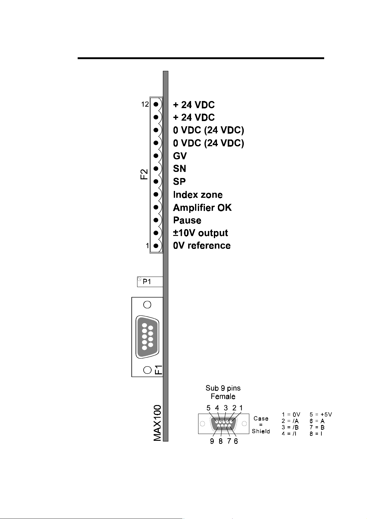
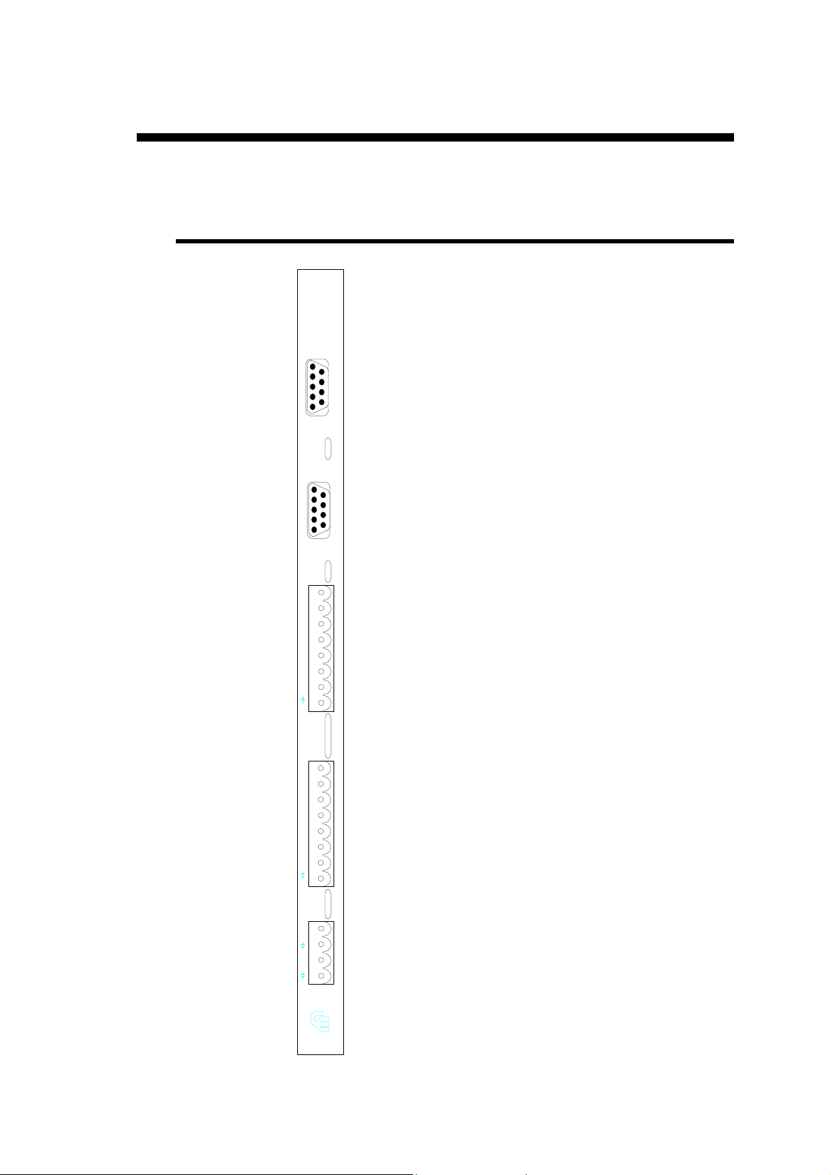
ARTE
C
MAX
N2X BOARD IMPLANTATION PAGE 9
Page 14

This page has been left blank intentionally.
PAGE 10 USER GUIDE N2X7
Page 15

N2X BOARD PARAMETERS
--AXES-- -X- Inherent
values
0 Axis type -- 0=DC DC/AC
1 Operating mode -- 0 DC/AC
2 Encoder resolution ---,--- 100,000 DC/AC
3 Positioning Tolerance -,-- 0,01 DC/AC
4 Advanced Stop -,-- 0,00 DC/AC
5 Overrun Dist +--,-- 0,00 DC/AC
6 Slow Speed Distance --,-- 0,00 DC/AC
7 SP/SN Time -,--- 0 DC/AC
8 Acceleration Time -,--- 0,500 DC
9 Deceleration Time -,--- 0,500 DC/AC
10 Positioning Speed ----,-- 30,00 DC
11 Final Approach Speed --,-- 0,00 DC
12 Indexing Speed ----,-- P10/2 DC
13 Manual Slow Speed ---,-- P10/8 DC
14 Manual High Speed ----,-- P10/2 DC
Types of
parameters
15 Preset Voltage +-,--- 0,000 DC
16 Maximum Voltage -,--- 9,999 DC
17 Minimum Voltage -,--- 0,000 DC
18 Offset Voltage +-,--- 0,000 DC
19 Closed loop tolerance (%) +-- 100 DC/AC
20 Max. Following Error --,-- disabled DC
21 Surveillance Time -,--- disabled DC/AC
22 Proportional Gain ---- 1000 DC
23 Integral Gain ---- 500 DC
24 Differential Gain ---- 0 DC
25 Index Mode -- 0 DC/AC
26 Index Position +-----,-- DC/AC
27 Minimum Limit - +-----,-- DC/AC
28 Maximum Limit + +-----,-- DC/AC
* Parameters temporarily not or partially in use
N2X BOARD PARAMETERS PAGE 11
Page 16

This page has been left blank intentionally.
PAGE 12 USER GUIDE N2X7
Page 17

CONVENTIONS AND DEFINITIONS
ONVENTIONS
C
U
NITS FOR THE "ENCODER RESOLUTION" PARAMETER
(P02)
All times are programmed in seconds.
All voltages are programmed in Volts.
Note: The unit of voltage for the parameters is the Volt (mV) to
facilitate their programming.
Example: 0.2 = 200 mV
All distances are in units.
All speeds are in units/s.
P
ARAMETERS WITH OPTIONS
The parameters which are programmed in bits (eg index mode and
operating mode) are defined by additioning the values of the chosen
bits:
D0 = data0 = Value 1
D1 2
D2 4
D3 8
D4 16
D5 32
D6 64
D7 128
Example: In a parameter where the bits of the chosen options are D0, D1,
D3 and D6, the programming is as follows: 1+2+8+64 = 75.
CONVENTIONS AND DEFINITIONS PAGE 13
Page 18

EFINITIONS
D
Master
SP
SN
HS
LS
D0
LSW+
LSW-
AC Axis
defines the numerical control software used by
the N2X.
The "Master" software is the part the operator
sees and uses.
Positive direction.
Negative direction.
High speed.
Low speed.
See parameter with options (previous page).
Maximum limit positive.
Minimum limit negative.
Defines a movement as described in the AC
positioning diagram page. It is a positioning
which manages for example a 2-speed three
phased (AC) unsynchronized motor. Not to be
confused with "brushless" motors.
DC Axis DC
Defines an axis movement commanded by a
nominal variable applied voltage of -10V to
+10V DC.
This management is suitable for conti nuous
current motors with servo-amplifiers,
"brushless" motors, unsynchronized motors
equipped with frequency servo-amplifiers with
an input voltage ±10V, etc.
PAGE 14 USER GUIDE N2X7
Page 19

AC POSITIONING DIAGRAM
(
)
with positive overrun
Slow speed dis tance
SP+HS
SP
Temp o
SP / SN
Overrun distance
SRET
NAX TYPE POSITIONING
Speed
Tolerance
Advanced stop(SAAV)
SN+HS
Fig. 1
without speed adjustment
Fig. 2
This type of positioning is selected by programming the proportional (P22)
and differential (P24) gain parameters at 0.
CONVENTIONS AND DEFINITIONS PAGE 15
Page 20

DC POSITIONING DIAGRAMS
U
NIDIRECTIONAL POSITIONING WITH FINAL APPROACH
OVERRUN AND ADVANCED STOP
B
IDIRECTIONAL POSITIONING WITH FINAL APPROACH
Fig. 3
PAGE 16 USER GUIDE N2X7
Fig. 4
Page 21

F
UNCTIONING OF FINAL APPROACH (DETAIL
Positioning value
Deceleration
time
Advanced stop
Final approach
speed
Slow speed
distance
Fig. 5
)
D
IRECT BIDIRECTIONAL POSITIONING
Positioning value
Acceleration
time
Deceleration
time
Fig. 6
Positioning
speed
CONVENTIONS AND DEFINITIONS PAGE 17
Page 22

This page has been left blank intentionally.
PAGE 18 USER GUIDE N2X7
Page 23

DESCRIPTION OF THE PARAMETERS
The number which precedes each parameter designates the parameter
described in this notice.
On certain CNC's, this number has no relation with the number of the
parameter of the same name which appears on the DNC.
The name of the parameter is used for reference.
A translation of these parameters is available at the end of this notice.
IMPORTANT:
The text which follows each parameter is its definition.
For adjustment of an axis, the procedure described in the "Parameter
adjustment" chapter (page 35) must be followed in order to understand the
interaction between the parameters.
P00 A
XIS TYPE
D0 & D1
D2 Rotary axis: P28 indicates the Modulo value of the axis.
D3
D4
Remark : The auto-offset system (D1 for P01) cannot be used in modes
Mode 0: DC Axis (±10V/SP/SN)
Mode 1: AC Axis or electrovalve (SP/SN/HS)
Mode 2: DC axis with a command voltage of
0 to +10V or 0 to -10V
The voltage polarity is determined by the
polarity of the parameter 15. (Preset Voltage)
With D2, the "Unotour" mode is accessed. In absolute movement, the N2X chooses the shortest possible way in order to
reach the position specified in the Modulo. Max. movement is 1
revolution.
DC axis (+/- 10V / validation)
The rotation direction is given by the polarity sign of the
voltage, the servo-amplifier being validated by the SP signal.
(Only N2XF_ & N2XE_)
1 and 2.
DESCRIPTION OF THE PARAMETERS PAGE 19
Page 24

P01 O
PERATING MODE
D0
D1
Closed loop:
In this mode the N2X makes sure that the axis does not move
away farther than the tolerance value (P03) of the target
position ( ⏐position⏐ ≤ ( ⏐target position⏐ ± tolerance)).
P19 indicates to the N2X at what distance from the target
position (% of P03) the regulator must be switched on.
DC axis
(D0, mode 0 or 2): PID is switched on.
AC axis
(D0, mode 1): An automatic positioning is carried out
immediately. This positioning will follow
the normal rules of the AC mode, i.e., with
overrun. If the bi-directional positioning
mode is chosen (without overrun), the axis
will "return" to the Slow speed distance
(P06) before positioning.
Offset recuperation:
The automatic offset compensation is active only at a standstill
when the axis is in the tolerance zone. If the offset is greater
than 100mV, the electric offsets must be regulated.
The N2X surveys the axis offset and will give a voltage in the
opposite direction to the axis movement.
Also functions for an open loop (DATA 0 not programmed). In
this case, the SP and SN outputs are permanently active. It is
not recommended to use this mode on its own but rather put it
with the closed loop regulation (D0 + D1).
D2
Positioning at maximum speed (not yet managed):
This operating mode permits rapid positioning. A very small or
zero acceleration time may also be chosen in this operating
mode.
The speed Vmax can only be obtained if a positioning speed
(P10) superior to the axis speed at maximum voltage (P16) is
programmed.
If however, the axis reaches the speed programmed in the P10
parameter, the N2X regulates the axis to a maximum at that
speed.
PAGE 20 USER GUIDE N2X7
Page 25

Positioning in "Positioning at maximum speed" mode (D2 = 1)
Maximum voltage (P16)
Fig. 7
D3
D4
D5
D6
Remark: If D5 and D6 are programmed simultaneously, only the D5
SP/SN signals not permanent in closed loop mode:
Operation identical to closed loop mode, except the SP and SN
signals are not active when the axis is within the tolerance zone
(see also P07 SP/SN TIME).
This mode may be used for an hydraulic axis, the SP/SN signals
could then manage ( by using the P07) the pressur ing up of the
valves.
In most cases, the automatic offset recuperation cannot be used
in this mode.
This mode is only valid if D0 is programmed.
Voltage Umin during regulation:
If this bit is programmed, the N2X does not take into account
the minimum operating volt age when it regulates at the
reference value with the integral gain.
Inversion of encoder count i ng direction ( quadrature mode).
Up/Down counting mode:
Input A = clock
Input B = counting direction.
function is validated, the D6 function being ignored.
DESCRIPTION OF THE PARAMETERS PAGE 21
Page 26

P02 E
NCODER RESOLUTION
This parameter defines the number of encoder impulses, that the DNC
receives per unit displayed (millimeters, degrees etc).
This parameter permits to work always with the maximum resolution allowed
by the encoder (using multiplication by 4).
This parameter allows to define a resolution up to 3 digits after the decimal
point.
This possibility allows to use practically any number of encoder impulses for
a given range and mechanical system.
The examples below demonstrate the use of this parameter. In the case where
the resolution does not allow to find a number of < 3 digits after the decimal
point, an example of the calculation of the resultant error allows you to
determine whether the error is acceptable or not.
Important : see P27
Examples
Lets take a mechanical kit, motor / ball screw directly coupled, to simplify the
examples.
Ball screw : pitch = 8mm/t
Example 1:
Display ----,--
Example 2:
Display ----,--
Example 3:
Display ----,--
MINIMUM LIMIT
Encoder:
200 imp/r.
Encoder:
250 imp/r.
Encoder:
100 imp/r.
, programming limit.
Resolution:
(200 * 4):8=100.000 that is 100 imp/mm
In this case we have 1 impulse per 100th
mm. (P02 = 100.000)
Resolution:
(250 * 4):8=125.000 that is 125 imp/mm
In this case there is no longer one impulse
per 100th mm.
The axis and the display behave as in
example 1. (P02 = 100.000)
Resolution:
(100 * 4):8=50.000 that is 50 imp/mm
In this case it is not possible to position
every 100th mm, but only every 2/100ths.
The display increments by 2/100ths.
Example 4:
Display ----,--
Example 5:
Display ----,--
PAGE 22 USER GUIDE N2X7
Encoder:
40 imp/r.
Ball screw : pitch = 15/32" (that is11,90625mm/t)
Encoder:
500 imp/r.
Resolution:
(40 * 4):8=20.000 that is 20 imp/mm
In this case the display increments by
5/100ths.
Resolution:
(500 * 4) : 11,90625 = 167,979
In this case the resolution allows correct
display for the whole length of the
trajectory, due to the 3 digits defined
after the decimal point.
Page 27

Ball screw : pitch = 5/8" (that is15,875mm/t)
Example 6:
Display ----,--
Distance covered : 1000mm
Theoretical number of impulses : 1000 x 125.984252 = 125984,252
Theoretical number of impulses = -125984,000
___________
Difference in number of impulses 0,252
Difference in mm 0.252 : 125.984252 = 0.002mm
Other method :
Programmed displacement * theoretical resolution
-----------------------------------------------------------------= effective distance
DNC resolution
1000 * 125,984252
--------------------------- = 1000.002 that is a difference of 0.002mm
125,984
Encoder:
500 imp/r.
Calculation of the accumulated error
Resolution:
(500 * 4) : 15,875 = 125,984252
In this case, the resolution obtained has
more than 3 digits after the decimal point.
(P02 = 125.984)
There will thus be an accumulated error
as a function of the distance covered.
The encod er giving the minimum error
for the distance covered must be selected.
P03 P
OSITIONING TOLERANCE
This parameter defines the distance around the positioning value in which the
axis is considered to be in position.
In order to execute a positioning, the axis must be outside the tolerance zone
of the chosen value. (AC or DC)
Note: See P01
AC Axis: With closed loop regulation (P01 = 1), if the axis is located
outside the tolerance zone, it immediately repositions
automatically. This positioning follows the normal positioning
rules for AC mode, that is with overrun. If two way positioning
is chosen (without overrun), the axis "overruns" at the
SPEED DISTANCE
The closed loop regulation operates when the axis lies within the tolerance
zone.
But, the axis is considered outside the tolerance zone (seen from the exterior)
the moment it passes the tolerance value.
(P06) before repositioning.
SLOW
DESCRIPTION OF THE PARAMETERS PAGE 23
Page 28

P04 A
DVANCED STOP
This parameter defines the distance in front of the programmed position
where the positioning orders and the voltage are cut.
This allows precise positioning of the axis by compensation of the breaking
distance due to the drive inertia.
Note: The advanced stop is not applied until the deceleration ramp
has been entered.
In the case of a positioning with final approach, the advanced
stop is not applied until after the final approach is started.
No positioning is possible in the
except when P05 is programmed greater than P04.
To prevent any troubles with AC axis, please programme P03
greater or equal than P04.
This parameter can also be used in order to accelerate the end of the
positioning of DC or brushless axes. When programming P03 = P04, the axis
card signals the end of the positioning as soon as the axis has reached the
tolerance zone of the target position.
ADVANCED STOP ZONE
,
P05 O
P06 S
VERRUN DISTANCE
The programming of this parameter allows a uni or bidirectional positioning
of the axis.
The
POSITIONING
defined).
For unidirectional positioning, the direction of the end of positioning is
defined by the polarity of this parameter:
+ = end of positioning in a positive direction (SP)
- = end of positioning in a negative direction (SN)
is bidirectional if this parameter is programmed at 0 (or not
LOW SPEED DISTANCE
DC axis
This parameter defines the distance of the final approach.
It is only active when the final approach must be equal to the overrun distance
(if programmed) in order for the positioning or overrun to be executed.
Note: Programming this parameter is unnecessary if NAX type
positioning is chosen.
AC axis
This defines the distance before the advanced stop where the engagement of
the axis is changed from high to slow speed (GV output).
If this parameter is programmed at 0, the positioning of the axis is made with
a single speed.
PAGE 24 USER GUIDE N2X7
Page 29

With DNC's equipped with N2X 102 or 103 boards, the GV output can only
be used if the indexation mode (P25) is defined without an index zone.
(Only one input-output is available either for the GV or the index zone).
P07 SP/SN T
DC axis
This delay is used in four different places:
IME
At the start of positioning where the SP/SN orders are not switched on.
This delay is used to introduce a dephasage between the switching on
of the SP/SN orders and the start of the management of the lead
voltage. This allows the system (eg. hydraulic pressure) to "prepare"
itself before the departure of the axis.
At the end of positioning at the overrun value.
After reaching the return value, the SP/SN delay is used to stabilize the
axis before starting positioning at the target value.
At the end of positioning on the target value.
After reaching the target value, the SP/SN orders are maintained (with
zero lead voltage) during the SP/SN delay to allow the servo-amplifier
to stabilize the axis at zero speed.
During closed loop regulation with D0 and D1 of P01 programmed:
when the axis leaves the tolerance zone, the SP/SN signals are
activated "SP/SN Time" seconds before the regulator intervenes.
Inversely, when the regulator has taken the axis to the aimed for value,
the same management is applied at the end of positioning at the aimed
for value.
Attention
For master softwares released before september 1990, (Refer to the list of main standard software below) and supplied with N2XDN, N2XEM, N2XFB and later software versions, the parameter P07 SP/SN Time (previously "overrun time") must be programmed to 0 with the following N2X softwares:
Main software list :
SNXEAE2 and later versions
SAXDAE2 and later versions
GTXDAB and later versions
VTXDAE and later versions
AC axis
This parameter corresponds to the waiting time before a change in the
positioning direction.
When changing the positioning direction, the positioning orders are stopped
for the time programmed in this parameter.
This allows time for the axis to stop before positioning in the other direction.
DESCRIPTION OF THE PARAMETERS PAGE 25
Page 30

P08 A
CCELERATION TIME
This parameter defines the linear acceleration time of the axis from 0 to the
POSITIONING SPEED
(P10).
P09 D
P10 P
ECELERATION TIME
DC axis
This parameter corresponds with the linear deceleration time of the axis form
the positioning speed (P10) to 0.
Note: When the software allows the operator to choose speeds less
than the "
positioning speed, the acceleration and deceleration times are
reduced and adapted automatically.
AC axis
This time corresponds to the axis stabilization time after the (SP/SN)
commands have been cut at the arrival at the advanced stop value.
Effectively, the cutting of the displacement commands being made at an
appreciable speed, the axis will continue, because of its inertia, to move
during a certain time before stabilizing on the positioning value. The P09 is
used to take into account this axis stabilization time before considering that
positioning is finished.
POSITIONING SPEED
OSITIONING SPEED
" (P10), for speeds less than the
This parameter defines the maximum axis speed for
mode.
Programming limits :
P10 * P02 < 2500.00 units/sec
P11 F
PAGE 26 USER GUIDE N2X7
INAL APPROACH SPEED
This parameter (if programmed) defines the type of DC positioning with final
approach.
It defines the axis speed at the end of positioning.
Programming limits:
P11 * P02 < 625.00 units/sec
POSITIONING
in automatic
Page 31

P12 I
NDEXING SPEED
This parameter defines the speed used to take up the index, or for leaving the
index zone.
If this parameter is not programmed, the index speed will be equal to half the
P10 speed.
Note : In AC mode, these movements will always be made at the
lowest speed.
Programming limits identical to P10.
P13 M
P14 M
ANUAL SLOW SPEED
This parameter defines slow speed in manual mode.
If this parameter is not programmed, the manual slow speed will be equal to
an 8th of the P10 speed.
ANUAL HIGH SPEED
This parameter defines high spee d in manual mode.
If this parameter is not programmed, the manual high speed will be equal to a
half of the P10 speed.
DESCRIPTION OF THE PARAMETERS PAGE 27
Page 32

P15 P
RESET VOLTAGE
This parameter determines the preset control voltage for an axis, regardless of
the influence of the P-I-D regulator.
This voltage is programmed for the maximum positioning speed (P10), and
automatically adapted proportionally for all other speeds (Manual,
acceleration, deceleration etc.).
For DC axes, programming of this parameter is especially useful for drive
systems which do not allow high gains. (E.g. hydraulic axes or drive systems
with considerable play).
The programmed value must not exceed the lead voltage for positioning at
maximum speed (P10).
If P15 has a negative sign, the applied voltage furnished by the N2X is
inversed. It is an inversion of the applied voltage polarity without changing
the references.
This parameter must be programmed for type 2 axes (controlled with a
voltage of 0 to +10 V or 0 to -10 V) and NAX-type positioning. (See "DC
axis in NAX mode", page 41).
The sign of the parameter determines the polarity of the lead voltage for a
type 2 axis.
Type 2 axis : commanded by a voltage included between 0 and 10 V only
or 0 and -10 V only.
P16 M
Programming limit :
The following ratio must be respected.
P15
--------- < 0,077
P10*P02
P15 [Volt]
P10 [units/s]
P02 [impulse/unit]
AXIMUM VOLTAGE
When calculating an output DA voltage, the axis card limits the voltage to a
maximum at that voltage at the value programmed in P16.
This voltage must correspond to the voltage with which the axis reaches its
maximum speed.
This parameter is optional but can be programmed to insure a certain safety if
at maximum speed the voltage is relatively weak (1 to 7 VDC for ex.).
PAGE 28 USER GUIDE N2X7
Page 33

P17 M
g
INIMUM VOLTAGE
This value is the minimum voltage which must be applied to the axis in order
to move it.
This parameter is particularly useful for overlap valves.
Example of an overlap valve :
Speed
Lead
voltage
Offset
Minimum volta
In this example, the offset voltage (P18) is used to make the two movement
directions symmetrical.
e
Fig. 8
DESCRIPTION OF THE PARAMETERS PAGE 29
Page 34

The figure above describes the functioning of the minimum operating voltage .
Ur (U regulator) being the voltage supplied by the regulator, to which is
superimposed the value of the offset and Umin, which gives the applied
voltage Uc (U applied) furnished by the axis card.
U
Umin
Offset
U r
t
P18 O
Note: The automatic offset compensation (D1 P01) is purposeless if
the system requires a minimum voltage.
FFSET VOLTAGE
Permits compensation of the drive offset.
(N2X board offset voltage, potential difference between the N2X, the servo-
driver etc.)
It can also be used to make the functioning of an overlap valve symmetric
(see figure 8).
Note: This parameter is added to the offset measured if an automatic
offset compensation is programmed (D1 P01).
Tolerance zone
Fig. 8a
PAGE 30 USER GUIDE N2X7
Page 35

P19 C
LOSED LOOP TOLERANCE
This parameter indicates to the N2X at what distance of the target position
(% of P03) the regulator must be activated in order to maintain the axis
within the positioning tolerance (P03).
See P01.
If this parameter is set to 0, with P01, Closed Loop, at 1, when the axis
regulates at the position, the voltage on the regulator is maintained even if
the axis returns to the tolerance zone, which in this case corresponds to
one impulse. In no rmal functioning mode, t he regulator d oes not intervene
any more as soon as the axi s has been brought back to its close d loop
position.
P20 M
P21 S
AXIMUM FOLLOWING ERROR
This parameter defines the maximum deviation between the theoretic and real
axis position.
If the maximum is exceeded, the positioning of the axis is stopped and an
error is displayed in the interactive field.
This is a security parameter. It is thus recommended to program it
correctly.
To do this, once the axis is perfectly adjusted, a series of positionings at full
speed should be made and this parameter reduced until the limit at which the
axis functions without creating any errors is found. T hen a value giving a
safety margin is programmed (increase approx. 20%).
The values found are largely dependant on the reaction time of the drive
system.
If not programmed = no test is made.
URVEILLANCE TIME
This parameter defines the maximum time which passes between the
reception of two impulsions by the axis board from the moment an axis
movement is commanded.
An error is signalled in the event of a malfunction.
If an error occurs, an emergency stop is made.
It is a security parameter. It is thus recommended to program it
correctly.
To do this, once the axis is perfectly adjusted, a series of positionings at
minimum spee d should be made and this parameter reduced until the limit at
which the axis functions without creating any errors is found. Then a value
giving a safety margin is programmed (increase approx. 20%).
The values found are largely dependant on the reaction time of the drive
system.
DESCRIPTION OF THE PARAMETERS PAGE 31
Page 36

P22 P
ROPORTIONAL GAIN
This gain intervenes during the entire positioning of the axis as well as during
the running of a closed loop.
This parameter corrects the difference between the real axis position and
theoretical trajectory.
P23 I
P24 D
NTEGRAL GAIN
The integral gain can intervene at the end of positioning when the theoretical
trajectory finishes before the end of positioning.
It is especially active during the closed loop regulation, when in position.
Note: The closed loop regulation in position is switched on as soon as the
axis has reached its tolerance value.
IFFERENTIAL GAIN
The differential regulation is active during the whole of positioning as well as
during a closed loop in position.
This parameter is used especially for stabilizing the drive system during
acceleration and deceleration.
Its programming is needed particularly for servo-valve drives and hydraulic
valves, and also for DC motor drives without tacho.
Note: Programming 0 on parameters P22 and P24 defines the NAX
type of functioning mode.
In this mode, no speed adjustment is made during positioning
until the beginning of the deceleration ramp is reached, and the
preset voltage (P15) is used.
A linear deceleration ramp is applied in relation to the
distanced covered (and not in relation to time).
PAGE 32 USER GUIDE N2X7
Page 37

P25 I
NDEX MODE
D0
D1
D2
D3
D4
D5
D6
If this parameter is not programmed, the DNC does not require an index on
the relevant axis.
An error is signalled if at the beginning of indexing, the axis lies on the index
zone, having programmed an index mode with an index zone but without an
automatic outlet from the zone.
if index zone 24 V
if index 5 V (if not indexing uniquely on the index zone)
if index take up in SN (if not SP)
when taking the index maintains the axis in the index zone. (If
not automatically leaves the index zone).
axis equipped with an absolute encoder (compatible).
(This option is only available on certain Master softwares).
Authorization to use relative 2 mode.
The counter is reset before the start of positioning (This option
is only available on certain Master softwares).
N2XF_ and N2XH_ only:
Set of continuous indexing mode. If the conditions set by D0
and D1 are respected, the axis will index. However, the D1
weight is essential.
P26 I
AC axes
For the AC axes, on the N2X 102 and 103 boards, a two-speed (GV) function
is not possible unless the index is 5 V, the index zone input being no longer
available (used for the HS output).
As only one Input/output is available per axis, the index zone function can
only be used if the AC axis is not using the HS output for a second speed.
The programming or not of operation with an index zone in this parameter
configurates the board with a "HS output" or an "index zone" input.
The programming of the slow speed distance also decides the utilization of
the output for the HS.
NDEX POSITION
This parameter defines the index position at which the axis counter is loaded
on reaching the index.
DESCRIPTION OF THE PARAMETERS PAGE 33
Page 38

P27 M
INIMUM LIMIT
This parameter defines minimum axis limit.
If this parameter is not programmed, the axis is never activated.
Attention: Certain software, having a configuration which can be
P
ROGRAMMING LIMITS FOR THE MINIMUM AND
-
modified, have the particularity to validate the axis using this
parameter.
It is thus indispensable to program this parameter as soon as the
machine is installed.
The non-programming of this parameter in this type of software
suppresses the axis display on the screen and necessitates a
modification of the axis wiring list.
P28 M
MAXIMUM LIMITS DEPENDING ON THE RESOLUTION
The programming of t he minimum and maximum limits and the resolution
encoder is limited to a ratio with the following formula :
(|P28 - P27|)*P02 must be less than 8386608
P28 = LSW+ in units
P27 = LSW- in units
P02 = Resolution encoder in impulses/unit
|P28 - P27| = physical separation between the LSWs
If P28 is programmed at 99999.99 and P27 at -99999.99, the maximum
RESOLUTION ENCODER
Note: only the overruns (or screw backlash adjustment) programmed in P5
will be able to bypass the electronic limit switches.
AXIMUM LIMIT
This parameter defines the maximum axis limit.
Its programming is necessary for security reasons.
P02 will be 41.000 imp/unit.
+
Programming limits : see P27
PAGE 34 USER GUIDE N2X7
Page 39

ADJUSTMENT OF THE AXES FUNCTION PARAMETERS
Important All parameters not mentioned will be considered as undefined.
Effectively, the different methods of adjustment take into
account their inherent values.
XIS AND VERIFICATION DEFINITIONS
A
Define the type of axis (P00):
Undefined = DC axis or brushless (±10 V)
Define the resolution encoder (P02):
Undefined = 100.000 impulse/mm
For DC or brushless axes:
Define the proportional gain (P22) at a low value (eg. 10).
Define the integral gain (P23) at 0.
Define the limits (LSW):
negative (P27) and positive (P28) with a sufficient safety margin, and
in such a way that they can be reached with a manual movement (see
P27 "Programming limits").
Load a value into the axis counter:
(Axis set) taking into account the same origin as for the definition of
the LSWs (P27 and P28).
ERIFICATION OF ROTATION AND COUNTING
V
DIRECTIONS
Verification of the applied voltage:
Make a number of brief manual movements (manual LS)
The rotational direction of the axis must correspond to that of the
command (manual + or manua l -).
If this is not the case two solutions are applicable:
a) Inverse the applied voltage connections
b) Program P15 at a negative value (eg. -0,001).
Verification of the encoder:
Make a number of brief manual movements (manual LS)
The counting direction (see position display) must correspond to that
of the command (manual + or manual -).
If this is not the case, inverse the encoder signals, or program the
inversion of the counting direction (D5 of P01).
ADJUSTMENT OF THE AXES PAGE 35
Page 40

FFSET ADJUSTMENT AND MINIMUM VOLTAGE
O
It is important to go through this stage of adjustment to balance the axis
function before starting adjustment of positioning.
AC axis (asynchronous 1 or 2 speed motors):
For an AC axis, it is not necessary to make this adjustment.
DC axis or brushless without minimum voltage:
able to remain in closed loop so the automatic offset compensation
does not cause any vibration.
Just program D1 of P01. Make a manual movement, then when
stopped verify that the system offset is less than 100mV.
Unable to remain in closed loop
a) Program the gain parameter P22 at 0.
b) Try a manual movement in both direc tions.
Program a voltage opposite to the direction of movement in the offset
voltage parameter (P18).
Adjust P18 until the axis movement is as little as possible.
Remark: If the absolute value of the measured offset voltage is greater
than 100 mV, the cause must be found in the system. Such a
high offset voltage is not considered to be normal.
Axis with overlap voltage: (See P17)
(Typically for proportional valves)
a) Program the parameters P17, P22 and P23 at 0.
b) Increase the minimum voltage (P17) until an axis movement in
either direction during a manual displacement command (
or
c) Retain this value (Ua).
d) Continue to increase P17 until an axis movement in the other
direction can be detected, and retain this value (Ub).
e) Program the value (Ua + Ub)/2 in the M
parameter.
f) The
overlap.
The
manner:
P18 = Ub - Umin (P17) if Ub corresponds to positive direction.
P18 = Umin (P17) - Ub if Ub corresponds to negative direction.
keys) can just be detected.
OFFSET VOLTAGE
OFFSET VOLTAGE
(P18) allows to symetrically adjust the
(P18) is programmed in the following
INIMUM VOLTAGE
(P17)
PAGE 36 USER GUIDE N2X7
Page 41

DJUSTING THE POSITIONING PARAMETERS
A
All positioning tests can be made (unless otherwise specified) with
movements in manual high speed (HS).
The positioning values to be reached being, in this case, the positive and
negative Limit Switches (LSW).
DC
AXIS WITH
Important: The use of a digital storage oscilloscope, connected to the lead
a) Program the
(P14) to the nominal positioning speed recommended by the
manufacturer.
b) Increase the
reach the level of HS speed (with a sufficiently long movement). That
is a stable applied voltage situated between +9,5V and -9,5V
depending o n the direction of movement.
PID
ADJUSTMENT
voltage, facilitates adjustment and interpretation of the results.
1) Determination of the POSITIONING SPEED parameter (P10)
POSITIONING SPEED
PROPORTIONAL GAIN
High speed positioning
(P10) and the
(P22) up to a value allowing to
MANUAL HIGH SPEED
~8-9V
Fig. 10
c) The lead voltage for the cruising speed should be in the region of 8V
or 9V (8V if important load variations are expected).
Three cases can be observed:
1. The lead voltage is located around the recommended values (Refer
to paragraph "Determination of the positioning speed (c)", page
37). The speed (P10) can be considered as correct.
ADJUSTMENT OF THE AXES PAGE 37
Page 42

2. The lead voltage is less than the recommended values (Refer to
paragraph "Determination of the positioning speed (c)", page 37).
If the programmed speed correspond in reality to the systems
maximum speed and the voltage for that speed is too weak
(<7V), the servo-amplifier must be adjusted so that it needs, for
this speed, a command voltage as near as possible to the
recommended values.
If on the contrary, the programmed speed does not correspond
to the maximum speed of the system, the P10 and P14 speeds
can be increased until the required voltage is obtained.
3. The lead voltage is greater than the recommended values (9,5 to
10V).
The programmed speed is too high and the system cannot function
in good conditions at this speed.
If the programmed speed really correspond to the performance
desired, either the system must be re-dimensioned (motor,
servo-amplifier), or the system's functioning checked to find the
cause of this unexpected performance.
In the opposite case, measure the voltage again by decreasing
the speeds P10 and P14 until the desired voltage is obtained.
2) Determination of the PROPORTIONAL GAIN (P22)
a) Increase the
PROPORTIONAL GAIN
progressively until oscillations
(vibrations) or an important overshoot of the target position (FC)
occurs.
Fig. 11
b) Program P22 at a value equal to the proportional gain as found above
less 10 to 20%.
3) Determination of the DIFFERENTIAL GAIN (P24)
Programming this parameter is not usually necessary for all axes fitted with a
currant loop.
In all cases P24 is useful for improving the acceleration / deceleration ramps.
It allows especially to program acceleration times which, without the
differential gain, would have saturated the lead voltage.
a) First program P24 at 1 then progressively increase its value until
either oscillations (vibrations) or an overshoot occur.
PAGE 38 USER GUIDE N2X7
Page 43

b) Program P24 at a value equal to the differential gain as found above
less 20%.
4) Determination of the ACCELERATION TIME (P08)
a) Program P08 at a value sufficient to allow to reach the maximum high
speed without saturating the lead voltage. (It is preferable to use an
oscilloscope on the lead voltage)
P08
~0,5 s
Fig. 12a
b) Decrease progressively the acceleration time until a saturation during
the acceleration ramp appears.
P08 saturation +/-10V
Fig. 12b
c) Program P08 at a value equal to the limit acceleration time as found
above plus 10 to 20%.
ADJUSTMENT OF THE AXES PAGE 39
Page 44

ok
Fig. 12c
5) Determination of the DECELERATION TIME (P09)
a) Program P09 at a value sufficiently high to allow to reach the target
value without overshooting.
b) Decrease progressively the deceleration time until an overshoot
appears.
c) Program P09 to a value equal to the limit deceleration time as found
above plus 10 to 20%.
6) Determination of the INTEGRAL GAIN (P23)
a) Increase progressively the integral gain until a deterioration in the
positioning precision (Overshoot) is noted.
b) Program P23 to a value equal to the limit integral gain as found above
less 10 to 20%.
Remark: This value must be further reduced if, in the case of a
positioning in a closed loop (D0 of P01), oscillations or
vibrations appear at the end of positioning.
Proceed with the final adjustment of the parameters (refer to page 44).
PAGE 40 USER GUIDE N2X7
Page 45

DC A
XIS IN
NAX
MODE (WITHOUT
PID
LOOP
)
This mode is selected by programming the
DIFFERENTIAL
This type of positioning is especially useful for the axes which do not support
the PID loop adjustment.
NAX positioning should also be easier to adjust for axes where performance
is not the main criteria.
1) Definition of the main parameters
Program the
taking into account the axis's dynamism.
Attention: A too short time would unnecessarily charge the system
Program, initially, a relatively long
(usually 1.000s).
Program the
manufacturer (the precision of this parameter is of only secondary
importance). Program P14 at the same value.
Program the
the maximum speed.
2) Determination of the FINAL APPROACH SPEED (P11) and the ADVANCED STOP (P04)
GAINS
(P24)
ACCELERATION TIME
(mechanics, motor, hydraulics etc.).
POSITIONING SPEED
PRESET VOLTAGE
to 0. (see NAX positioning diagram)
PROPORTIONAL
(P08) as short as possible but
DECELERATION TIME
(P10) recommended by the
(P15) at the voltage necessary to reach
(P22) and
(P09)
a) Program, initially, a
POSITIONING SPEED
the
b) Decrease progressively this value (P11) until relatively precise
positioning is obtained.
c) Regulate the value of the
as precise as possible.
3) Determination of the DECELERATION TIME (P09)
a) Decrease progressively the value of the
until a deterioration of the positioning precision is noted.
b) Program P09 to a value equal to the deceleration time as found above
plus 10 to 20%.
4) The INTEGRAL GAIN (P23)
can be determined, if you wish to use it, in the same way as in chapter
"Determination of the integral gain" (page 40).
FINAL APPROACH SPEED
(P10).
ADVANCED STOP
(P11) equal to 10% of
(P04) to obtain positioning
DECELERATION TIME
(P09)
ADJUSTMENT OF THE AXES PAGE 41
Page 46

AC A
XIS
1) Definition of the main parameters
a) For unidirectional positioning:
1 Program, initially, a relatively long
(eg. 15% of the maximum axis movement).
The polarity of this parameter defines the direction in which you
wish positioning to be finished.
2 Program, initially, an SP/SN
2.000s).
b) For a 2 speed AC axis :
Program, initially, a relatively long LS
the maximum axis movement ).
c) The
a) Program P04 at 0 or verify that it is not programmed.
b) Make several manual LS movements (
c) Note the axis overshoot in relation to the reference position (the limit
DECELERATION TIME
dephasage between the cutting of the SP/SN orders and the end of
positioning signal.
2) Determination of the ADVANCED STOP (P04)
direction in which positioning must finish. These movements must be
made right up to the limit switch so that the axis can finish its
positioning.
switch) and program this value on the advanced stop (P04).
parameter (P09) can be used to introduce a
OVERRUN DISTANCE
TIME
(P07) relativel y high ( eg.
DISTANCE
(P06) (eg. 10% of
or key) in the
(P05)
d) Make several other movements, of different lengths, (always on the
limit switch and in manual LS) and regulate, if necessary, the
ADVANCED STOP
obtained.
3) Determination of the LS DISTANCE (P06)
(only for a 2 speed AC axis)
a) Make several movements, up to the limit switch, in manual LS (always
in the direction of the end of positioning) then decrease progressively
the LS distance until the positioning precision diminishes.
b) Program P06 at a value equal to the limit LS distance as found above
plus 10 to 20%.
(P04) until a positioning as precise as possible is
PAGE 42 USER GUIDE N2X7
Page 47

4) Determination of the SP/SN TIME (P07)
(only for unidirectional positioning)
a) Make several positioning with overrun (in auto and semi-auto) and
observe, on the motor or position display, where the axis stops before
changing direct ion.
b) Decrease progressively the SP/SN
(P07) until the axis changes
TIME
direction before stopping completely.
c) Program P07 at a value equal to the limit overrun time as found above
plus 10 to 20%.
5) Determination of the OVERRUN DISTANCE (P05)
(only for unidirectional positioning)
a) Make several positioning, with overrun, of different lengths (in auto
and semi-auto) then decrease progressively the
OVERRUN DISTANCE
(P05) until the positioning precision diminishes.
b) Program P05 at a value equal to the limit overrun distance as found
above plus 10 to 20%.
ADJUSTMENT OF THE AXES PAGE 43
Page 48

INAL REGULATION OF THE PARAMETERS
F
P
ROGRAMMING THE SECONDARY PARAMETERS
Closed loop (DO P01), Tolerance (P02), High speed voltage (P15), etc.
1) Regulation of the MINIMUM and MAXIMUM LIMIT S (P27 and P28)
Program the min imum and maximu m limits for normal use of the axis .
2) Programming the INDEX MODE (P25)
(If you wish the origin to be taken automatically)
Regulation of the i ndex value (P26).
Programming, if necessary, of the indexing speed (P12)
3) Verification and regulation of positioning
Finally several positioning (in auto and semi auto) must be made with long,
average and then very short (minimum movement which can be asked of the
axis) movements in both directions. Then regulate (if necessary) certain
parameters to improve the precision or the rapidity of positioning.
For the DC axes, P14 (Vmax/2 by default) can be deleted or programmed at
the desired value.
PAGE 44 USER GUIDE N2X7
Page 49

ST
INDEXATION OF THE
1
Note : The availability of this function depends on the "master"
software.
N2X
AXES
P
ROCEDURE
a) switch on the DNC or reset.
b) position the stop manually against a known reference value (or against
c) select the axis set page (key in position 2), execute the set of the
d) select the Machine parameter pages (key in position 3)
e) press the start key
Remark : the taking of the index can only be done separately, axis by
the die for the X axis), or measure its position exactly.
axis(es), (refer to the DNC programming manual).
- program the index mode required.
- position the cursor on the "index value" field.
- the axis goes to take its index.
- once the index is found, the DNC displays the "Index OK"
message in the interactive field.
axis.
ADJUSTMENT OF THE AXES PAGE 45
Page 50

This page has been left blank intentionally.
PAGE 46 USER GUIDE N2X7
Page 51

DDITIONAL
A
Choice of the 8 I/O
configuration
N2X
In some cases, it's necessary to implant one or two axes managed by the
master. The additional axes should not be complicated, only some operating
modes are implanted. This or theses additional axes use inputs/ouputs and the
encoder of the Y2 Axis (1
On DNC 60, it's possible to implant one axis at the master, for this, choose
the 8 I/O configuration on the MACHINE PARAMETERS 01 and search
configuration by default in the inputs/outputs pages or configure at least the
output SP X3. When this is done, on the first machine parameters page, N2X
software version is displayed.
The parameters who are not longer managed, are displayed with a dot after
the parameter's number.
SOFTWARE ON MASTER
st
definite axis) or Y1.
N2X software on master
MACHINE PARAMETERS -01- IGNORE
Softs: GIXMDP/ZIAMBA3 PIC:AA5
N2XMnf/ZZAMBA3 N2XSA1 Key:0
Language: [GB] FR GB DE IT ES PT SE NL
CONFIGURATION 8 I/O: 1
X1: X1 X2: X2
00 Axis type __ __
01 Operating mode __ __
02 Encoder reso. (I/mm) ___.___ ___.___
03 Tolerance 0.05 0.05
04 Advanced stop _.__ _.__
05 Overrun distance ___.__ ___.__
06 Slow speed distance __.__ __.__
07 SP / SN time _.___ _.___
08 Acceleration time 0.300 0.300
09 Deceleration time 0.400 0.400
OUTPUT CONFIGURATION IGNORE
Put 1 in this field to
find configuration by
default
SEARCH CONFIGURATION BY DEFAULT _
--- MB6 J10 --- 10100000
09: CuthAuth 10: Blade Up
11: F1Dig SP 12: F1Dig SN
13: F2Dig SP 14: F2Dig SN
15: F5Dig SP 16: F5Dig SN
--- MB6 J11 --- 00000000
09: 10:
11: 12:
13: 14:
15: SP X3 16: SN X3
N2X SOFTWARE ON MASTER
PAGE 47
Page 52

N2X
PARAMETERS
For a complete description, see the paragraph above corresponding to the
parameter.
- D0 & D1: Mode 0 (DC Axis +/-10V/SP/SN), mode 1 (AC Axis) et mode 2
(DC Axis with a command voltage of 0 to +10V or 0 to –10V) controlled,
mode 3 non-controlled
- D4 DC Axis (+/-10V / Validation) controlled
- The other bits are not controlled.
- D0 Closed loop, makes a repositioning when leaving the positioning
tolerance (mode DC et AC).
- D5 Inversion of t he counting dire ction.
- The other bits are not controlled.
P00 Axis Type
P01 Operating Mode
P02 Encoder resolution
- Parameter controlled according to N2X description.
P03 Positioning tolerance
- Parameter controlled according to N2X description.
P04 Advanced stop
- Parameter controlled according to N2X description.
P05 Overrun distance
- Parameter controlled according to N2X description.
P06 Slow speed distance
- Parameter controlled according to N2X description.
P07 SP/SN Time
- Parameter controlled only in AC mode.
P08 Acceleration time
- This parameter defines the linear acceleration time of the axis from the
offset voltage to preset voltage (P15).
PAGE 48
P09 Deceleration time
- This parameter is used for the calculation of the braking ramp in case of
stopping or returning.
USER GUIDE N2X7
Page 53

P10 Positioning speed
- This parameter is used for the voltage calculation for:
- Positioning normal mode
- Positioning manual mode
- Positioning indexation mode.
P11 Final approach speed
- This parameter is used for the voltage calculation of the final approach. At
the end of positioning, the output voltage is limited to the final approach
voltage, even if the calculated voltage is lower.
P12 Indexing speed
- this parameter is used for the voltage calculation of the maximum voltage
when indexing.
P13 P14 Manual slow speed and Manual high speed
- These parameters are used for the calculation of the manual voltages SS and
HS.
P15 Preset voltage OBLIGATORY parameter
- This parameter is used as maximum voltage for the movements in
positioning speed. For the other movement types, the used voltage is only a
proportion of this voltage.
Example:
Manual slow speed
Manual voltage SS = Preset voltage —————————
Positioning speed
- If the sign of this machine parameter is negative, the output voltage is
inverted (same as N2X).
P16 Maximum voltage
- Parameter non-controlled.
P17 Minimal operating voltage
- Parameter non-controlled.
P18 Offset voltage
- Parameter controlled according to N2X description.
P19 Closed loop tolerance
- Parameter non-controlled.
P20 Maximum following error
- Parameter non-controlled.
N2X SOFTWARE ON MASTER
PAGE 49
Page 54

P21 Encoder surveillance time
- Parameter non-controlled.
P22 Proportional gain
- This parameter is used for the calculation of the voltage to apply on the
axis. The output voltage is equal to the remaining distance up to the aimed
dimension multiplied by the proportional gain. The resulting voltage is
limited to the final approach voltage and the limitation voltage according to
the movemen t type.
P23 Integral gain
- Parameter non-controlled.
P24 Differential gain
- Parameter non-controlled.
P25 Index mode
- Parameter partially controlled. The controlled data are the followings:
- D0 if 24V indexation zone.
- D1 if index 5V.
- D2 if index research in SN.
- D3 if axis blocking in the index zone with error message. No
automatic output possible.
- The other bits are not controlled.
P26 Index position
- Parameter controlled according to N2X description.
P27 et P28 Minimum limit - and maximum limit +
- Parameter controlled according to N2X description.
PAGE 50
USER GUIDE N2X7
Page 55

E
XAMPLE
Attention: In this example, only minimums parameter which allow the
AC 2
SPEED MOTOR
operation of the axis have a value.
MACHINE PARAMETERS -01- IGNORE
Softs: GIXMDP/ZIAMBA3 PIC:AA5
N2XSA1 Key:0
Language: [GB] FR GB DE IT ES PT SE NL
CONFIGURATION 8 I/O: 1
X3: X3
00 Axis type 1
01 Operating mode 1
02 Encoder reso. (I/mm) 100.000
03 Tolerance 0.1
04 Advanced stop 0.2
05 Overrun distance ___.__
06 Slow speed distance 1.50
07 SP / SN time 0.2
08 Acceleration time _.___
09 Deceleration time 0.400
MACHINE PARAMETERS -02- IGNORE
X3: X3
10 Positioning speed 30.00
11 Fin.approach speed __.__
12 Indexing speed ____.__
13 Manual slow speed ___.__
14 Manual high speed ____.__
15 A priori voltage __.___
16.Maximum voltage
17.Minimum voltage
18 Offset voltage __.___
19.Closed loop toler.
20.Max. follow.error
21.Surveillance time
22 Proportional gain _____
23 Integral gain
N2X SOFTWARE ON MASTER
PAGE 51
Page 56

(
)
MACHINE PARAMETERS -03- IGNORE
X3: X3
24 Differential gain
25 Index mode 2
26 Index position 980.35
27 Min. limit - 50.00
28 Max. limit + 1000.00
The parameters at undef ( __.__ ) allow to improve the adjustment of the axis.
Some parameters have a default value in spite of the fact they are at undef.
See the description in the paragraph N2X Board parameters.
SP+HS
Tempo
SP / SN
Slow speed distance
SP
Overrun distance
SRET
Speed
Tolerance
Advanced stop(SAAV)
SN+HS
PAGE 52
USER GUIDE N2X7
Page 57

E
XAMPLE
Attention: In this example, only minimums parameter which allow the
DC M
OTOR
operation of the axis have a value.
+/- 10VDC
MACHINE PARAMETERS -01- IGNORE
Softs: GIXMDP/ZIAMBA3 PIC:AA5
N2XSA1 Key:0
Language: [GB] FR GB DE IT ES PT SE NL
CONFIGURATION 8 I/O: 1
X3: X3
00 Axis type 0
01 Operating mode 1
02 Encoder reso. (I/mm) 100.000
03 Tolerance 0.1
04 Advanced stop _.__
05 Overrun distance ___.__
06 Slow speed distance 1.50
07 SP / SN time _.___
08 Acceleration time 0.300
09 Deceleration time 0.400
MACHINE PARAMETERS -02- IGNORE
X2: X2
10 Positioning speed 130.00
11 Fin.approach speed 5.00
12 Indexing speed 50.00
13 Manual slow speed ___.__
14 Manual high speed ____.__
15 A priori voltage +9.400
16.Maximum voltage
17.Minimum voltage
18 Offset voltage __.___
19.Closed loop toler.
20.Max. follow.error
21.Surveillance time
22 Proportional gain 10
23 Integral gain
N2X SOFTWARE ON MASTER
PAGE 53
Page 58

MACHINE PARAMETERS -03- IGNORE
X2: X2
24 Differential gain
25 Index mode 1
26 Index position 983.50
27 Min. limit - 35.00
28 Max. limit + 1000.00
The parameters at undef ( __.__ ) allow to improve the adjustment of the axis.
Some parameters have a default value in spite of the fact they are at undef.
See the description in the paragraph N2X Board parameters.
.
PAGE 54
USER GUIDE N2X7
Page 59

INDEX
1st indexation, 45
AC Axis, 14, 42
AC Positioning, 15
Acceleration time, 26, 41, 48
Adjustment, 35
Advanced stop, 24, 41, 42, 48
Axis display, 34
Axis is never activated, 34
Axis Type, 19, 48
Axis wiring list, 34
Bits, 13
Closed loop, 20, 25, 32
Closed loop tolerance, 49
Conventions, 13
Copyright, 3
Counting, 35
D0, 14
Index position, 33, 50
Index zone, 25
Indexing speed, 27, 49
Inertia, 24
Integral gain, 32, 40, 41, 50
Inversion of encoder count i ng, 21
Inversion polarity, 28
License, 3
LS, 14
LS
DISTANCE
LSW-, 14
LSW+, 14
Manual high speed, 27, 49
Manual slow speed, 27, 49
Master, 14, 25
Maximum following error, 31, 49
Maximum limit +, 34, 50
, 42
DC Axis, 14, 41
DC positioning, 16
Deceleration time, 26, 40, 41, 42, 48
Definitions, 14
Delay, 25
Differential gain, 32, 41, 50
Direction, 35, 42
Encoder resolution, 48
Encoder surveillance time, 50
End of positioning, 25
Final approach speed, 26, 41, 49
Final regulation, 44
Gain, 35, 36
HS, 14
Hydraulic axes, 28
Hydraulic valve, 32
Important, 35
Maximum voltage, 28 , 49
Minimal opera ting voltage, 49
Minimum limit -, 34, 50
Minimum voltage, 29
Motor drives without tacho, 32
N2X software on master, 47
NAX, 41
NAX positioning, 41
NAX type positioning, 15
Offset, 20, 30, 36
Offset voltage, 30, 49
Operating Mode, 20, 48
Oscillations, 38, 40
Overlap, 36
Overlap valves, 29
Overrun, 25
Overrun distance, 24, 42, 43, 48
Impulses, 22
Index, 27, 33
Index mode, 33, 50
INDEX PAGE 55
Overshoot, 38, 40
Parameters with options, 13
PID adjustment, 37
Page 60

Polarity, 28
Positioning speed, 26, 37, 41, 49
Positioning tolerance, 48
Preset voltage, 28, 41, 49
Programming limits, 26, 27, 34
Proportional gain, 32, 37, 41, 50
Proportional valves, 36
Resolution, 22, 34
Saturation, 39
Security, 31
Servo-valve, 32
Slow speed distance, 24, 48
SN, 14
SP, 14
SP/SN time, 25, 42, 43
SP/SN Time, 48
Surveillance time, 31
Tolerance, 23, 49
Units, 13
Up/Down counting mode, 21
Values, 11, 13
Vibration, 36, 38, 40
Warranty, 3
PAGE 56 USER GUIDE N2X6
 Loading...