


 Loading...
Professional Shop Manual
RZT-S
NOTE: These materials are for use by trained technicians who are experienced in the service and repair of outdoor power equipment of the kind described in this publication, and are not intended for use by untrained or inexperienced individuals. These materials are intended to provide supplemental information to assist the trained technician. Untrained or inexperienced individuals should seek the assistance of an experienced and trained professional. Read, understand, and follow all instructions and use common sense when working on power equipment. This includes the contents of the product’s Operators Manual, supplied with the equipment. No liability can be accepted for any inaccuracies or omission in this publication, although care has been taken to make it as complete and accurate as possible at the time of publication. However, due to the variety of outdoor power equipment and continuing product changes that occur over time, updates will be made to these instructions from time to time. Therefore, it may be necessary to obtain the latest materials before servicing or repairing a product. The company reserves the right to make changes at any time to this publication without prior notice and without incurring an obligation to make such changes to previously published versions. Instructions, photographs and illustrations used in this publication are for reference use only and may not depict actual model and component parts.
© Copyright 2012 MTD Products Inc. All Rights Reserved
MTD Products Inc. - Product Training and Education Department
Table of Contents
Chapter 1: Introduction
Professional Shop Manual intent . . . . . . . . . . . . . . . . . . . . . . . . . . . . . . . . . . . 1
Fasteners . . . . . . . . . . . . . . . . . . . . . . . . . . . . . . . . . . . . . . . . . . . . . . . . . . . . . 1 Assembly . . . . . . . . . . . . . . . . . . . . . . . . . . . . . . . . . . . . . . . . . . . . . . . . . . . . . 3
Description of the RZT-S . . . . . . . . . . . . . . . . . . . . . . . . . . . . . . . . . . . . . . . . . 3
Model and Serial Numbers . . . . . . . . . . . . . . . . . . . . . . . . . . . . . . . . . . . . . . . 4
Chapter 2: Engine related parts
Muffler . . . . . . . . . . . . . . . . . . . . . . . . . . . . . . . . . . . . . . . . . . . . . . . . . . . . . . . 5
Fuel tank removal/replacement . . . . . . . . . . . . . . . . . . . . . . . . . . . . . . . . . . . . 6 Fuel pick up tube . . . . . . . . . . . . . . . . . . . . . . . . . . . . . . . . . . . . . . . . . . . . . . . 8
Fuel Line . . . . . . . . . . . . . . . . . . . . . . . . . . . . . . . . . . . . . . . . . . . . . . . . . . . . . . 9 Evaporative (EVAP) emissions system . . . . . . . . . . . . . . . . . . . . . . . . . . . . . . 10 Roll over valve vent . . . . . . . . . . . . . . . . . . . . . . . . . . . . . . . . . . . . . . . . . . . . . 12
Control cable adjustment . . . . . . . . . . . . . . . . . . . . . . . . . . . . . . . . . . . . . . . . 14
Chapter 3: Body
Floor pan . . . . . . . . . . . . . . . . . . . . . . . . . . . . . . . . . . . . . . . . . . . . . . . . . . . . . 15
Left fender . . . . . . . . . . . . . . . . . . . . . . . . . . . . . . . . . . . . . . . . . . . . . . . . . . . . 17
Right fender . . . . . . . . . . . . . . . . . . . . . . . . . . . . . . . . . . . . . . . . . . . . . . . . . . 18 Seat box assembly . . . . . . . . . . . . . . . . . . . . . . . . . . . . . . . . . . . . . . . . . . . . . 20
Chapter 4: Brake and Drive System
Brake system description . . . . . . . . . . . . . . . . . . . . . . . . . . . . . . . . . . . . . . . . 23 Brake adjustment . . . . . . . . . . . . . . . . . . . . . . . . . . . . . . . . . . . . . . . . . . . . . . 24
Brake puck/rotor replacement . . . . . . . . . . . . . . . . . . . . . . . . . . . . . . . . . . . . . 25
Brake shaft Bushings . . . . . . . . . . . . . . . . . . . . . . . . . . . . . . . . . . . . . . . . . . . 28 Drive belt . . . . . . . . . . . . . . . . . . . . . . . . . . . . . . . . . . . . . . . . . . . . . . . . . . . . . 30
Drive belt adjustment . . . . . . . . . . . . . . . . . . . . . . . . . . . . . . . . . . . . . . . . . . . 32
Hydro neutral control adjustment . . . . . . . . . . . . . . . . . . . . . . . . . . . . . . . . . . 38 Control pedal shaft assembly . . . . . . . . . . . . . . . . . . . . . . . . . . . . . . . . . . . . . 41
Chapter 5: Steering
Introduction . . . . . . . . . . . . . . . . . . . . . . . . . . . . . . . . . . . . . . . . . . . . . . . . . . . 47
Wheel alignment and drive control link adjustments . . . . . . . . . . . . . . . . . . . 48
Front wheels . . . . . . . . . . . . . . . . . . . . . . . . . . . . . . . . . . . . . . . . . . . . . . . . . . 51 Front yokes . . . . . . . . . . . . . . . . . . . . . . . . . . . . . . . . . . . . . . . . . . . . . . . . . . . 53
Removal of the steering gears . . . . . . . . . . . . . . . . . . . . . . . . . . . . . . . . . . . . 54
Drag links . . . . . . . . . . . . . . . . . . . . . . . . . . . . . . . . . . . . . . . . . . . . . . . . . . . . 58
I
Chapter 6: electrical system
Introduction . . . . . . . . . . . . . . . . . . . . . . . . . . . . . . . . . . . . . . . . . . . . . . . . . . . 61
PTO Switch . . . . . . . . . . . . . . . . . . . . . . . . . . . . . . . . . . . . . . . . . . . . . . . . . . 63 Brake Switch . . . . . . . . . . . . . . . . . . . . . . . . . . . . . . . . . . . . . . . . . . . . . . . . . . 63
Reverse Safety Switch . . . . . . . . . . . . . . . . . . . . . . . . . . . . . . . . . . . . . . . . . . 64
Seat Safety Switch . . . . . . . . . . . . . . . . . . . . . . . . . . . . . . . . . . . . . . . . . . . . . 64 Starter solenoid . . . . . . . . . . . . . . . . . . . . . . . . . . . . . . . . . . . . . . . . . . . . . . . . 65
PTO Relay . . . . . . . . . . . . . . . . . . . . . . . . . . . . . . . . . . . . . . . . . . . . . . . . . . . 65
Start Circuit . . . . . . . . . . . . . . . . . . . . . . . . . . . . . . . . . . . . . . . . . . . . . . . . . . . 66 Run Circuit . . . . . . . . . . . . . . . . . . . . . . . . . . . . . . . . . . . . . . . . . . . . . . . . . . . 69
Engine shut-down circuits . . . . . . . . . . . . . . . . . . . . . . . . . . . . . . . . . . . . . . . . 70
Charging circuit . . . . . . . . . . . . . . . . . . . . . . . . . . . . . . . . . . . . . . . . . . . . . . . . 71 PTO Circuit . . . . . . . . . . . . . . . . . . . . . . . . . . . . . . . . . . . . . . . . . . . . . . . . . . . 76
Diagnostic Techniques . . . . . . . . . . . . . . . . . . . . . . . . . . . . . . . . . . . . . . . . . . 78
Electronics . . . . . . . . . . . . . . . . . . . . . . . . . . . . . . . . . . . . . . . . . . . . . . . . . . . 78
Electrical environment: AC Vs. DC . . . . . . . . . . . . . . . . . . . . . . . . . . . . . . . . . 79
Ohm’s Law . . . . . . . . . . . . . . . . . . . . . . . . . . . . . . . . . . . . . . . . . . . . . . . . . . . 80
Kirchhoff’s current law . . . . . . . . . . . . . . . . . . . . . . . . . . . . . . . . . . . . . . . . . . . 80 Kirchhoff’s voltage law . . . . . . . . . . . . . . . . . . . . . . . . . . . . . . . . . . . . . . . . . . 81
How the system is wired together . . . . . . . . . . . . . . . . . . . . . . . . . . . . . . . . . 81
Types of circuits . . . . . . . . . . . . . . . . . . . . . . . . . . . . . . . . . . . . . . . . . . . . . . . 82 Series . . . . . . . . . . . . . . . . . . . . . . . . . . . . . . . . . . . . . . . . . . . . . . . . . . . . . . . 82
Parallel . . . . . . . . . . . . . . . . . . . . . . . . . . . . . . . . . . . . . . . . . . . . . . . . . . . . . . 82
Series/parallel . . . . . . . . . . . . . . . . . . . . . . . . . . . . . . . . . . . . . . . . . . . . . . . . . 83 Shorts . . . . . . . . . . . . . . . . . . . . . . . . . . . . . . . . . . . . . . . . . . . . . . . . . . . . . . . 83
Opens . . . . . . . . . . . . . . . . . . . . . . . . . . . . . . . . . . . . . . . . . . . . . . . . . . . . . . 83
Increased resistance . . . . . . . . . . . . . . . . . . . . . . . . . . . . . . . . . . . . . . . . . . . 83 The Tools . . . . . . . . . . . . . . . . . . . . . . . . . . . . . . . . . . . . . . . . . . . . . . . . . . . . 84
Digital Multi-meter . . . . . . . . . . . . . . . . . . . . . . . . . . . . . . . . . . . . . . . . . . . . . . 85
Wiring diagram or schematic . . . . . . . . . . . . . . . . . . . . . . . . . . . . . . . . . . . . . 86 Fused jumper wires . . . . . . . . . . . . . . . . . . . . . . . . . . . . . . . . . . . . . . . . . . . . . 86
Test lights. . . . . . . . . . . . . . . . . . . . . . . . . . . . . . . . . . . . . . . . . . . . . . . . . . . . 86
Self-powered continuity lights . . . . . . . . . . . . . . . . . . . . . . . . . . . . . . . . . . . . . 86
Ammeters and specialized charging system testers . . . . . . . . . . . . . . . . . . . . 87
Batteries . . . . . . . . . . . . . . . . . . . . . . . . . . . . . . . . . . . . . . . . . . . . . . . . . . . . . 88 Charging the battery . . . . . . . . . . . . . . . . . . . . . . . . . . . . . . . . . . . . . . . . . . . 88
Checking battery condition . . . . . . . . . . . . . . . . . . . . . . . . . . . . . . . . . . . . . . . 89
Battery Testers . . . . . . . . . . . . . . . . . . . . . . . . . . . . . . . . . . . . . . . . . . . . . . . . 90 Adjustable load testers . . . . . . . . . . . . . . . . . . . . . . . . . . . . . . . . . . . . . . . . . . 90
Fixed load testers . . . . . . . . . . . . . . . . . . . . . . . . . . . . . . . . . . . . . . . . . . . . . . 91
Conductance testers . . . . . . . . . . . . . . . . . . . . . . . . . . . . . . . . . . . . . . . . . . . 91 Battery discharge test . . . . . . . . . . . . . . . . . . . . . . . . . . . . . . . . . . . . . . . . . . . 92
Storage of batteries . . . . . . . . . . . . . . . . . . . . . . . . . . . . . . . . . . . . . . . . . . . . 92 Electrical Troubleshooting . . . . . . . . . . . . . . . . . . . . . . . . . . . . . . . . . . . . . . . . 93 Voltage Drop Test . . . . . . . . . . . . . . . . . . . . . . . . . . . . . . . . . . . . . . . . . . . . . . 95 Testing switches . . . . . . . . . . . . . . . . . . . . . . . . . . . . . . . . . . . . . . . . . . . . . . . 98
II
Diodes . . . . . . . . . . . . . . . . . . . . . . . . . . . . . . . . . . . . . . . . . . . . . . . . . . . . . . 99
Relay . . . . . . . . . . . . . . . . . . . . . . . . . . . . . . . . . . . . . . . . . . . . . . . . . . . . . . . 101
Schematic . . . . . . . . . . . . . . . . . . . . . . . . . . . . . . . . . . . . . . . . . . . . . . . . . . . 102
Chapter 7: Decks and lift shaft
Cutting decks . . . . . . . . . . . . . . . . . . . . . . . . . . . . . . . . . . . . . . . . . . . . . . . . 103
Cleaning the deck . . . . . . . . . . . . . . . . . . . . . . . . . . . . . . . . . . . . . . . . . . . . . 104 To clean the deck while it is removed . . . . . . . . . . . . . . . . . . . . . . . . . . . . . . 104
Blades . . . . . . . . . . . . . . . . . . . . . . . . . . . . . . . . . . . . . . . . . . . . . . . . . . . . . . 105
Deck belt . . . . . . . . . . . . . . . . . . . . . . . . . . . . . . . . . . . . . . . . . . . . . . . . . . . . 107 Idler pulleys . . . . . . . . . . . . . . . . . . . . . . . . . . . . . . . . . . . . . . . . . . . . . . . . . . 109
Spindle shafts . . . . . . . . . . . . . . . . . . . . . . . . . . . . . . . . . . . . . . . . . . . . . . . . 111
Spindle removal/installation . . . . . . . . . . . . . . . . . . . . . . . . . . . . . . . . . . . . . . 112 Spindle overhaul . . . . . . . . . . . . . . . . . . . . . . . . . . . . . . . . . . . . . . . . . . . . . . 113
Leveling the deck . . . . . . . . . . . . . . . . . . . . . . . . . . . . . . . . . . . . . . . . . . . . . 115
Front To Rear (pitch) Leveling . . . . . . . . . . . . . . . . . . . . . . . . . . . . . . . . . . . 116
Deck Gauge Wheel Adjustment . . . . . . . . . . . . . . . . . . . . . . . . . . . . . . . . . . 117
Deck lift shaft assembly . . . . . . . . . . . . . . . . . . . . . . . . . . . . . . . . . . . . . . . . 118
Chapter 8: Maintenance intervals
Lubrication . . . . . . . . . . . . . . . . . . . . . . . . . . . . . . . . . . . . . . . . . . . . . . . . . . 121
Engine maintenance . . . . . . . . . . . . . . . . . . . . . . . . . . . . . . . . . . . . . . . . . . . 121
The spark plugs . . . . . . . . . . . . . . . . . . . . . . . . . . . . . . . . . . . . . . . . . . . . . . 122 Air filter . . . . . . . . . . . . . . . . . . . . . . . . . . . . . . . . . . . . . . . . . . . . . . . . . . . . . 123
Oil change . . . . . . . . . . . . . . . . . . . . . . . . . . . . . . . . . . . . . . . . . . . . . . . . . . . 124
Oil filter . . . . . . . . . . . . . . . . . . . . . . . . . . . . . . . . . . . . . . . . . . . . . . . . . . . . . 125 Fuel system . . . . . . . . . . . . . . . . . . . . . . . . . . . . . . . . . . . . . . . . . . . . . . . . . . 126
Servicing the fuel system . . . . . . . . . . . . . . . . . . . . . . . . . . . . . . . . . . . . . . . . 126
Fuel filter . . . . . . . . . . . . . . . . . . . . . . . . . . . . . . . . . . . . . . . . . . . . . . . . . . . . 126 Clean the engine . . . . . . . . . . . . . . . . . . . . . . . . . . . . . . . . . . . . . . . . . . . . . . 127
Transmissions . . . . . . . . . . . . . . . . . . . . . . . . . . . . . . . . . . . . . . . . . . . . . . . . 127
III
IV

Introduction
CHAPTER 1: INTRODUCTION
Professional Shop Manual intent
This Manual is intended to provide service dealers with an introduction to the mechanical aspects of the RZT-S zero-turn mower.
•Detailed service information about the engine will be provided by the engine manufacturer, in most cases.
Disclaimer: The information contained in this manual is correct at the time of writing. Both the product and the information about the product are subject to change without notice.
About the text format:
NOTE: is used to point out information that is relevant to the procedure, but does not fit as a step in the procedure.
•Bullet points: indicate sub-steps or points.
|
|
|
|
|
|
|
|
|
|
Caution is used to point out potential danger to the technician, operator, bystanders, or sur- |
|
|
|
! CAUTION |
|
||
|
|
|
rounding property. |
|
|
|
|
|
|
|
|
|
|
|
|
|
|
|
|
|
|
|
|
|
|
|
|
|
|
|
|
|
|
Warning indicates a potentially hazardous situation that, if not avoided, could result in death of |
|
|
|
! WARNING |
|
||
|
|
|
serious injury. |
|
|
|
|
|
|
|
|
|
|
|
|
|
|
|
|
|
|
|
|
|
|
|
|
|
|
|
|
|
|
Danger indicates an imminently hazardous situation that, if not avoided, will result in death or |
|
|
|
! DANGER |
|
||
|
|
|
serious injury. This signal word is to be limited to the most extreme situations. |
|
|
|
|
|
|
|
|
|
|
|
|
|
|
Disclaimer: This manual is intended for use by trained, professional technicians.
•Common sense in operation and safety is assumed.
•In no event shall MTD or Cub Cadet be liable for poor text interpretation or poor execution of the procedures described in the text.
•If the person using this manual is uncomfortable with any procedures they encounter, they should seek the help of a qualified technician or Cub Cadet Technical Support.
Fasteners
•Most of the fasteners used on these mowers are sized in fractional inches. The engine and transmissions are metric. For this reason, wrench sizes are frequently identified in the text, and measurements are given in U.S. and metric scales.
•If a fastener has a locking feature that has worn, replace the fastener or apply a small amount of releasable thread locking compound such as Loctite® 242 (blue).
•Some fasteners like cotter pins are single-use items that are not to be reused. Other fasteners such as lock washers, retaining rings, and internal cotter pins (hairpin clips) may be reused if they do not show signs of wear or damage. This manual leaves that decision to the judgement of the technician.
1
RZT-S
|
|
|
• |
Be prepared in case of emergency: |
|
|
! CAUTION |
|
|||
|
|
|
Keep a fire extinguisher nearby |
|
|
|
|
|
|
Keep a first aid kit nearby |
|
|
|
|
|
Keep emergency contact numbers handy |
|
|
|
|
• |
Replace any missing or damaged safety labels on shop equipment. |
|
|
|
|
• |
Replace any missing or damaged safety labels on equipment being serviced. |
|
|
|
|
|
|
|
|
|
|
|
|
|
|
|
|
• |
Grooming and attire: |
|
|
! WARNING |
|
|
Do not wear loose fitting clothing that may become entangled in equipment. |
|
|
|
|
|
Long hair should be secured to prevent entanglement in equipment. |
|
|
|
|
|
||
|
|
|
|
Jewelry is best removed. |
|
|
|
|
• |
Protective gear: includes, but is not limited to |
|
|
|
|
|
Clear eye protection ................................ |
while working around any machinery |
|
|
|
|
Protective gloves ..................................... |
where necessary |
|
|
|
|
Armored footwear .................................... |
when working around any machinery |
|
|
|
|
Hearing protection ................................... |
in noisy environments |
|
|
|
|
Chemically resistant gloves ..................... |
when working with chemicals or solvents |
|
|
|
|
Respirator ................................................ |
when working with chemical or solvents |
|
|
|
|
Appropriate tinted eye protection............. |
when cutting or welding |
|
|
|
|
Flame resistant headgear, jacket, chaps . when cutting or welding |
|
|
|
|
|
|
|
•Remember that some hazards have a cumulative effect. A single exposure may
! CAUTION |
cause little or no harm, but continual or repeated exposure may cause very serious |
harm. |
•Clean spills and fix obviously dangerous conditions as soon as they are noticed.
•Lift and support heavy objects safely and securely.
•Be aware of your surroundings and potential hazards that are inherent to all power equipment. All the labels in the world cannot protect a technician from an instant of carelessness.
! DANGER
•Exhaust fumes from running engines contain carbon monoxide (CO). Carbon monoxide is a colorless odorless gas that is fatal if inhaled in sufficient quantity. Only run engines in well ventilated areas. If running engines indoors, use an exhaust evacuation system with adequate make-up air ventilated into the shop.
2

Introduction
Assembly
Torque specifications may be noted in the part of the text that covers assembly, they may also be summarized in tables along with special instructions regarding locking or lubrication. Whichever method is more appropriate will be used. In many cases, both will be used so that the manual is handy as a quick-reference guide as well as a step-by- step procedure guide that does not require the user to hunt for information.
The level of assembly instructions provided will be determined by the complexity of dis-assembly/reassembly, and by the potential for unsafe conditions to arise from mistakes made in assembly.
Some instructions may refer to other parts of the manual for subsidiary procedures. This avoids repeating the same procedure two or three times in the manual.
Description of the RZT-S
The RZT-S combines a traditional RZT lap bar zero turn rider (ZTR) with Cub Cadet’s patented Syncro SteerTM technology.
The magic of the system: variable ratio steering gears that turn the front wheels much further than conventional systems. The steering control is linked to the traction drive system control.
|
The traction drive system synchronizes the steering |
|
angle of the front tires with the speed and direction of rota- |
|
tion of the rear tires. |
|
A true zero-turn maneuver is achieved when the opera- |
|
tor turns the steering wheel far enough that the inside rear |
|
wheel spins in reverse just like a traditional lap-bar con- |
Figure 1.1 |
trolled ZTR. |
3
RZT-S
Model and Serial Numbers
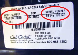
The model and serial number tag can be found under the seat. See Figure 1.2.
The serial number is located to the right of the model number as shown above. See Figure 1.2.
Figure 1.2
The model number is 17WF2BDS055. The break down of what the number mean is as follows:
1 .............................................................................................. |
Residential machine |
....7 .......................................................................................... |
Residential zero turn mower |
.......W. ..................................................................................... |
Returnable crate |
...........F.................................................................................... |
Engine code |
.............2. ................................................................................ |
Frame |
.................B............................................................................. |
Transmission (B = EZT, G = ZT2800) |
....................D.......................................................................... |
Style series |
.........................S..................................................................... |
Deck (S = 42”, T = 46”, P=50”) |
.............................056 ............................................................. |
Customer number |
The serial number is 1B142H20124. The serial number reads as follows: |
|
1 .............................................................................................. |
Engineering level |
..B............................................................................................ |
Month of production (B = February) |
.....14 ....................................................................................... |
Day of the month |
.........2 ..................................................................................... |
Last digit of the year |
...........H................................................................................... |
Plant it was built in (Martin, TN) |
..............2 ................................................................................ |
Assembly line number |
.................0124 ....................................................................... |
Number of unit built |
4
Engine Related Parts
CHAPTER 2: ENGINE RELATED PARTS
This chapter will cover the engine accessories that are manufactured by Cub Cadet.
IMPORTANT: The engine is supplied by Kohler. Refer to the Kohler manual for engine specific service information.
Muffler
Remove the muffler by following these steps:
Bumper |
1. Remove the four screws (two on each side) that hold |
|
the rear bumper in place using a 1/2” wrench. |
Screws |
See Figure 2.1. |
2. Slide the bumper out from between the frame, the fuel tank bracket on the right and utility bin bracket on the left.
NOTE: The muffler guard will come off with the bumper.
Figure 2.1
exhaust screws
 Exhaust pipe
Figure 2.2
3.Remove the two screws that hold each exhaust pipe to the cylinder head using a T-27 torx driver.
See Figure 2.2.
4.Remove the muffler and exhaust pipes.
NOTE: The exhaust pipes are welded to the muffler. The pipes and the muffler are serviced as one assembly.
5.Clean and remove all gasket material from the cylinder head (and the exhaust pipe if they are being reused).
6.Using new gaskets, install the muffler by following the previous steps in reverse order.
NOTE: Tighten the exhaust screws to a torque of 150 in lbs (17Nm).
NOTE: When installing the bumper, start all four screws before tightening them. Otherwise the bumper will bind and the holes will not line up.
7.Test drive the mower in a safe area before returning it to service.
IMPORTANT: Do not put a mower with an exhaust leak back in service.
5
RZT-S
Fuel System
Fuel tank removal/replacement
Remove/replace the fuel tank by following these steps:
Gasoline and its vapors are extremely flammable. Use common sense when working around
the fuel system.
1. Remove the left fender:
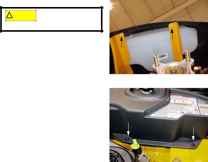
1a. Remove the two screws, indicated by the arrows in Figure 2.3, from the underside of the fender using a 3/8” wrench.
NOTE: The left rear wheel was removed for a clear view of the screws.
Figure 2.3
1b. Remove the two screws, indicated by the arrows in Figure 2.4, from the inboard side of the fender using a T-27 torx driver.
Figure 2.4
6
Engine Related Parts
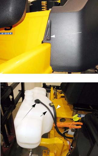
1c. Remove the screw from the front of the fender using a T-27 torx driver. See Figure 2.5.
1d. Unscrew the fuel cap.
Screw
NOTE: The fuel cap is tethered to the fender. This is an EPA tier III requirement.
1e. Lift the fender off of the mower.
Figure 2.5
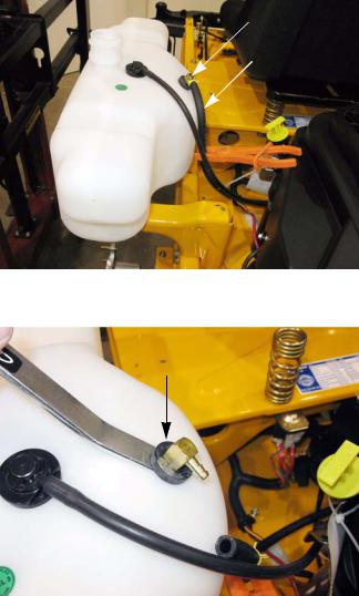
Vent hose Roll over valve
Figure 2.6
Fuel line |
2. |
Clamp off the fuel line between the fuel tank and the |
|
|
fuel filter. See Figure 2.6. |
|
3. |
Disconnect the fuel line from the fuel tank at the fuel |
|
|
filter. |
|
4. |
Disconnect the fuel tank vent line from the roll over |
|
|
valve. |
|
5. |
Lift the fuel tank off of the mower. |
|
6. |
Drain the fuel into an approved container. |
|
7. |
Install the fuel tank by reversing previous steps. |
|
8. |
Test drive the mower in a safe area before returning |
|
|
it to service. |
7
RZT-S
Fuel pick up tube
The fuel tank on the RZT-S mower has a fuel pick up tube. This is a rigid tube that runs from the bottom of the tank to the top of the tank were the fuel line attaches to it.
NOTE: A loose or missing pick up tube will allow air into the fuel system and will reduce or prevent fuel follow from the fuel tank to the engine.
To remove/replace the pick up tube:
1.Remove the left fender by following the procedures described in Chapter 3: Body.
2.Clamp off the fuel line between the fuel tank and the fuel filter. See Figure 2.7.
3.Disconnect the fuel line from the pick up tube.
Pick up tube
Fuel line
Figure 2.7
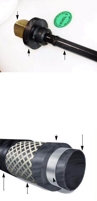
4. |
Gently pry the pick up tube and grommet out of the |
Grommet |
|
fuel tank. See Figure 2.8. |
|
5.Inspect the grommet.
NOTE: If the grommet is cracked or damaged, replace as needed.
Figure 2.8
8
Engine Related Parts
Fitting
Grommet
pick up tube
Figure 2.9
Fuel Line
NBR intermediate layer NBR inner liner
CSM Cover Reinforcement 
THV barrier layer
Figure 2.10
Picture courtesy of Avon Automotive
6.Inspect the pick up tube. See Figure 2.9.
NOTE: If the pick up tube is loose or missing, it must be replaced.
7.Install the grommet in the fuel tank.
8.Insert the pick up tube into the fuel tank, through the grommet.
9.Re-connect the fuel line.
10.Install the left fender.
11.Test run the mower in a safe area before returning it to service.
The fuel line used by Cub Cadet is GREENbarTM. This is a multi-layer fuel line that meets the current EPA guidelines.
NOTE: This fuel line has a thin inner liner. If a tear forms in this inner liner, fuel can get between the liner and the hose. This will cause the liner to collapse, cutting off the fuel flow.
NOTE: Replace the fuel line only with GREENbarTM 700 series fuel line.
9
RZT-S
Evaporative (EVAP) emissions system
The EPA has enacted rules that regulate the amount of vapors an engine’s fuel system is allowed to vent to the atmosphere. The rules are know as tier III emissions guidelines. These rules apply to all engines built on or after 1/1/ 2012. Some of the requirements of tier III emissions include:
•Tethered fuel caps.
•Unvented fuel caps.
•Low permeation (GREENbarTM) fuel line
•Roll over valve vents
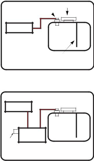
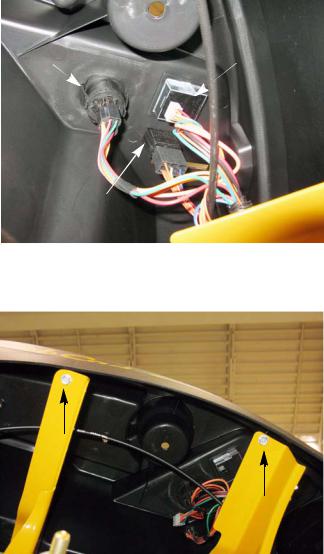
The fuel tank has an unvented fuel cap. The fuel tank vents through the roll over valve. The vapors will flow through the vent hose (black hose with a red trace) to the engine. See Figure 2.11.
The EVAP system, from the fuel tank up to the engine connector, is a Cub Cadet system, meaning warranty and parts are handled by Cub Cadet.
The engine side of the system varies by engine manufacturer, but on most engines the vent hose will go to the air intake manifold.
Roll over valve |
Fuel cap |
%NGINE
Fuel tank
Fuel pick up tube
49 state fuel system
Figure 2.11
NOTE: Units sold in California will have a charcoal |
|
|
|
canister to further reduce the amount of |
%NGINE |
||
emissions that escape from the fuel system. |
|||
The fuel tank will vent through the charcoal |
|
|
|
canister. The charcoal in the canister will act |
|
|
|
as a filter and remove some of the vapors |
|
|
|
that are venting out of the fuel tank. |
|
#HARCOAL |
|
A second vent hose connects the canister to |
|
||
6ENT |
CANISTER |
||
the engine. As the engine runs, the vacuum |
|||
in the intake manifold will draw the vapors |
|
|
|
out of the charcoal, recharging it. |
|
California fuel system |
|
See Figure 2.12. |
|
||
NOTE: A leak in the vent hose will allow dirt injec-
tion in the engine. This will not affect engine Figure 2.12 performance until the dirt ingestion has
cause damage inside the engine.
10
Engine Related Parts
|
Troubleshooting |
|
|
Symptom |
Cause |
|
|
|
|
Engine starts, then dies |
A blockage in the vent hose. |
|
The roll over valve is stuck closed. |
|
|
Engine runs rich |
Raw gasoline in the charcoal canister (if equipped). |
|
A blockage in the line between the charcoal canister (if |
|
equipped) and the intake manifold. |
|
|
Engine runs lean |
Wrong fuel cap installed. |
|
Leak in the vacuum lines. |
|
|
Gasoline vapor escaping from |
The charcoal canister (if equipped) is saturated. |
the engine |
A blockage in the line between the charcoal canister (if |
|
|
|
equipped) and the intake manifold. |
|
Wrong fuel cap installed. |
|
Leak in the vacuum lines. |
|
|
11
RZT-S
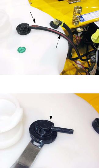
Roll over valve vent
To remove the roll over valve:
1.Remove the left fender by following the procedures described in Chapter 3: Body.
2.Disconnect the vent hose. See Figure 2.13. NOTE: The vent hose will have a red trace.
3.Gently pry the roll over valve out of the fuel tank. See Figure 2.14.
4.Inspect the rubber grommet, replace if damaged.
To install the roll over valve:
1.With the grommet on the roll over valve, install the roll over valve by pressing it into the opening in the tank.
2.Install the vacuum line.
3.Install the left fender.
4.Test run the engine in a safe area before returning to service.
Vent hose
Red trace
Figure 2.13
Roll over valve
Figure 2.14
12
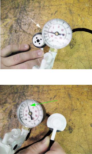
Testing the roll over valve
15 in.Hg.
Figure 2.15
Zero reading
Figure 2.16
Engine Related Parts
The roll over valve vent has two functions. The first function is to vent the tank and the second function is to close off the vent if the tank is inverted.
Test the roll over valve by:
1.Remove the roll over valve by following the steps previously described in this section.
2.Connect a vacuum pump to the roll over valve.
3.Hold the roll over valve in an inverted position.
4.Apply a vacuum to the roll over valve. See Figure 2.15.
NOTE: The roll over valve should hold 15 in.Hg. for 15 seconds.
5.With the vacuum still applied, turn the roll over valve over. See Figure 2.16.
NOTE: The vacuum should be relieved.
6.If the results do not match what is listed above, replace the roll over valve.
13
RZT-S
Control cable adjustment
To adjust the control cable:
1.Move the throttle lever to the detent between the full throttle and the choke position.
2.Loosen the clamp that holds the control cable jacket in position. See Figure 2.17.
3.Slide the cable jacket until the speed control lever makes contact with the choke lever.
4.Tighten the control cable jacket.
5.Move the throttle lever to the choke position.
6.Verify that the choke is fully closed.
7.Test run the mower in a safe area before returning it to service.
Choke lever
Contact point 
Speed control lever
Control cable clamp
Figure 2.17
14
Body
CHAPTER 3: BODY
Floor pan
To remove/replace the floor pan: 1. Remove the steering wheel:
1a. Turn the steering wheel so that the wheels are
pointing straight ahead.
Screw
1b. Gently pry the cover off of the steering wheel.
1c. Remove the screw and washer that secures the steering wheel to the steering shaft using a 1/2” wrench. See Figure 3.1.
1d. Lift the steering wheel off of the steering shaft.
Figure 3.1
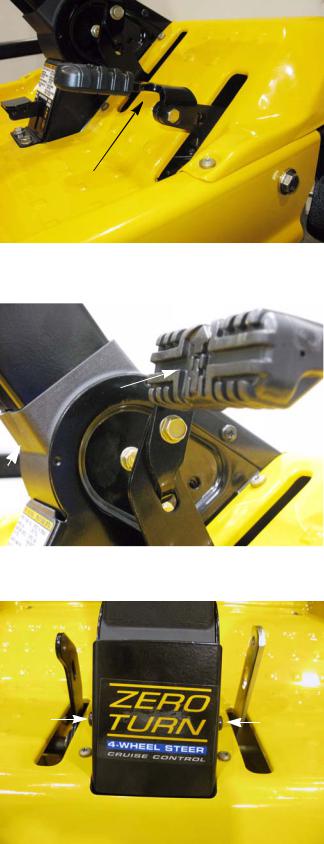
2. Remove the brake pedal: See Figure 3.2.
2a. Remove the screw that secures the brake pedal to the pedal shaft bell crank using a 1/2” wrench.
2b. Unhook the brake pedal from the bell crank.
Brake pedal
Pedal shaft bell crank
Figure 3.2
15
Z-Force-S
3.Remove the reverse pedal using a pair of 7/16” wrenches. See Figure 3.3.
4.Remove the forward drive pedal: See Figure 3.4.
4a. Remove the screw that secures the drive pedal to the pedal shaft bell crank using a 1/2” wrench.
4b. Unhook the drive pedal from the bell crank.
Reverse pedal
Figure 3.3
Forward drive pedal
Figure 3.4
5.Remove the lower steering column cover by removing the two screws, indicated by the arrows in Figure 3.4, using a T-30 torx driver.
6.Remove the nine screws that hold the floor pan to the frame using a T-30 torx driver.
7. Lift the floor pan off of the mower.
8.Install the floor pan by reversing the previous steps.
NOTE: Confirm that all safety and control features work correctly. Do Not return an unsafe mower to service.
Figure 3.5
16

Body
Left fender
To remove/replace the left fender:
NOTE: The fuel tank is nested inside the left fender.
Gasoline and its vapors are extremely flammable. Use common sense when working around
the fuel system.
1. Remove the two screws, indicated by the arrows in Figure 3.6, from the underside of the fender using a 3/8” wrench.
NOTE: The left rear wheel was removed for a clear view of the screws.
Figure 3.6
2. Remove the two screws, indicated by the arrows in Figure 3.7, from the inboard side of the fender using a T-27 torx driver.
Figure 3.7
3. |
Remove the screw from the front of the fender using |
|
a T-27 torx driver. See Figure 3.8. |
4. |
Unscrew the fuel cap. |
Screw |
|
NOTE: The fuel cap is tethered to the fender. This is an |
|
|
EPA tier III requirement. |
5. |
Lift the fender off of the mower. |
6. |
Install the fender by following the previous steps in |
|
reverse order. |
|
NOTE: Confirm that all safety and control features work |
|
correctly. Do Not return an unsafe mower to ser- |
Figure 3.8 |
vice. |
|
17
Z-Force-S
Right fender
To remove/replace the right fender:
1.Remove the yellow throttle lever using a #1 phillips screwdriver. See Figure 3.9.
2.Disconnect the throttle lever assembly from the right fender using a T-30 torx driver. See Figure 3.9.
3.Remove the two screws, indicated by the arrows in Figure 3.10, from the inboard side of the fender using a T-27 torx driver.
4.Remove the screw from the front of the fender using a T-27 torx driver. See Figure 3.11.
5.Remove the deck lift lever grip.
Figure 3.9
Figure 3.10
Screw
Figure 3.11
18
Key switch |
Hour meter |
PTO switch
Figure 3.12
Figure 3.13
Body
6.Disconnect the key switch. See Figure 3.12.
7.Disconnect the hour meter.
8.Disconnect the PTO switch.
9.Remove the two screws from the underside of the right fender using a 3/8” wrench. See Figure 3.13.
10.Lift the fender off of the mower.
11.Install the fender by following the previous steps in reverse order.
12.Test drive the mower in a safe area before returning it to service.
NOTE: Confirm that all safety and control features work correctly. Do Not return an unsafe mower to service.
19
Z-Force-S
Seat box assembly
To remove/replace the seat box assembly:
1.Remove the battery.
2.Remove the deck by following the procedures described in Chapter 7: Decks and Lift Shaft.
3.Remove the left fender by following the procedures described in the left fender section of this chapter.
4.Remove the right fender by following the procedures described in the right fender section of this chapter
5.Disconnect the harness from the seat switch.
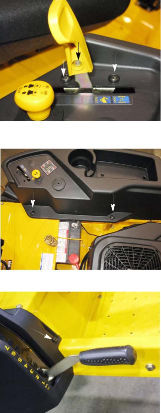
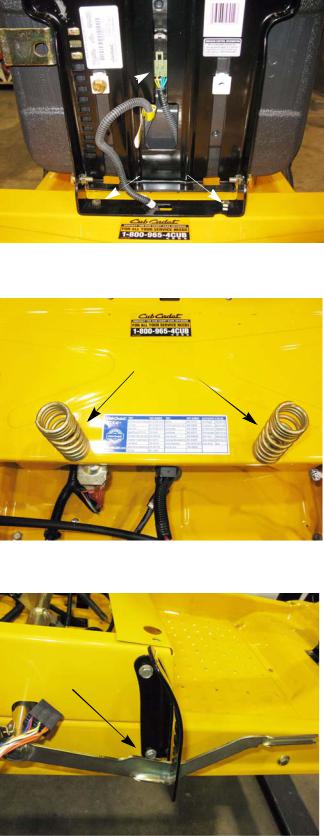
6.Remove the two screws securing the seat frame to the seat box using a 1/2” wrench. See Figure 3.14.
7.Remove both of the seat springs using a 1/2” wrench. See Figure 3.15.
8.Remove the seat box cover using a 1/2” wrench.
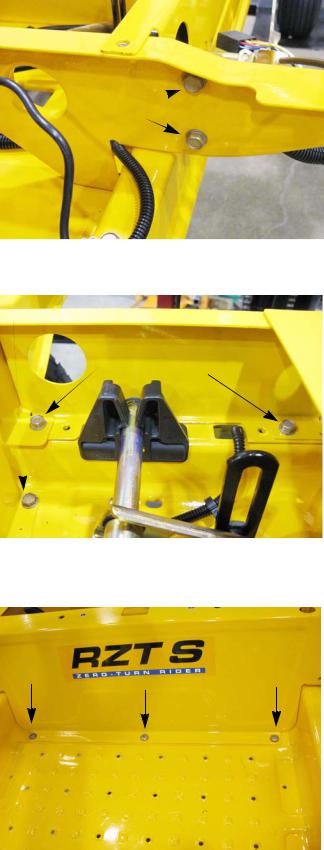
9.Remove the two screws that hold the deck lift indexing bracket to the seat box using a 1/2” wrench. See Figure 3.16.
Harness
Screws
Figure 3.14
Seat springs
Figure 3.15
Screws 

Figure 3.16
20
Screws 
Figure 3.17
Cross member screw
Seat box screws
Figure 3.18
Figure 3.19
Body
10.Remove the four screws (two on each side), securing the seat box to the cross member using a 1/2” wrench. See Figure 3.17.
11.Remove the four screws (two on each side), that hold the seat box to the frame using a 1/2” wrench.
See Figure 3.18.
12.Remove the two screws (one on each side), that hold the cross member to the frame
NOTE: The cross member can be left in place.
13.Remove the three pan head screws indicated by the arrows in Figure 3.19, that hold the front of the seat box to the frame using a T-30 torx driver.
14.Fish the wiring harness out of the seat box.
15.Lift the seat box assembly off of the mower.
16.Install the seat box by reversing the previous steps.
17.Test drive the mower in a safe area before returning it to service.
NOTE: Confirm that all safety and control features work correctly. Do Not return an unsafe mower to service.
21
Z-Force-S
22
Brakes and Drive System
CHAPTER 4: BRAKE AND DRIVE SYSTEM
Brake system description
The RZT-S uses twin EZT Hydro-Gear transmissions to drive the rear wheels. The hydraulic action of the transmissions will provide the braking for the mower while it is in motion. There is a friction brake on the transmission that is used as a parking brake.
Brake pedal
Main brake 
 control rod
Figure 4.1
•There is a brake for each transmission.
•They are activated by depressing the brake pedal.
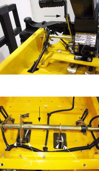
•Depressing the brake pedal will cause the control pedal shaft to rotate. When the shaft rotates, a bell crank attached to it will pull on the main brake control rod. See Figure 4.1.
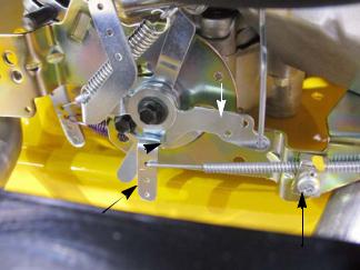
Brake shaft
Main brake |
De-clutching rod |
control rod |
Secondary brake rods |
|
Figure 4.2 |
•The main brake rod will pull on a bell crank attached to the brake shaft. This will cause the brake shaft to rotate.
NOTE: The brake shaft is held captive on the deck lift shaft. It is serviced with the deck lift shaft. Refer to the deck lift shaft section of Chapter 7: Decks and Lift Shaft for removal/replacement procedures.
•As the brake shaft rotates, the two bell cranks will pull the secondary brake rods. The secondary brake rods will pull on the brake caliper arm, pushing the brake pins into the caliper, applying the brakes. See Figure 4.2.
•A brake link rod connects the right brake shaft bell crank to the drive belt idler pulley bracket. When the brakes are applied, this link rod pulls on the idler pulley bracket, de-clutching the drive belt.
23
RZT-S
Brake adjustment
NOTE: When performing a brake adjustment, inspect the brake components for signs of wear or damage.
1.Block the front wheels.
2.Lift and safely support the rear of the mower. NOTE: Make sure the parking brake is released.
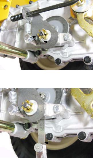
3.Remove the cotter pin locking the castle nut on the brake caliper. See Figure 4.3.
4.Back the castle nut off a few turns using a 9/16”
wrench. |
Castellated nut |
NOTE: Even if the brakes are set to the correct clearance, inserting a feeler gauge between the rotor and the brake puck can be very difficult. Loosen the castle nut first, then insert the feeler gauge and tighten the nut to set the proper clearances
5.Insert a 0.030” (0.8 mm) feeler gauge between the brake rotor and the outboard brake puck.
See Figure 4.4.
NOTE: The tolerance for the brake clearance is 0.020” - 0.040” (0.5 - 1.0mm). The 0.030 feeler gauge will set the clearance at the midpoint.
6.Tighten the nut until there is slight drag on the feeler gauge.
 Cotter pin
Figure 4.3
NOTE: For even braking, both sides should be set to the same clearance.
7.Install a new cotter pin.
8.Repeat same procedure on the other side.
 0.030” feeler gauge
Figure 4.4
9.Take the mower off of the jack stands.
10.Open the bypass valves and check the parking brake before returning the mower to service.
•With the brakes released, the mower should have only hydraulic drag when it is pushed.
•With the brakes engaged, the wheels should slide before they rotate when the mower is pushed.
11.Test drive the mower in a safe area before returning it to service.
NOTE: Check all safety and control features. Do Not return an unsafe mower to service.
24
Loading...