


 Loading...
Professional
Shop Handbook
4x4 Utility Vehicle w/Kohler Engine
NOTE: These materials are for use by trained technicians who are experienced in the service and repair of outdoor power equipment of the kind described in this publication, and are not intended for use by untrained or inexperienced individuals. These materials are intended to provide supplemental information to assist the trained technician. Untrained or inexperienced individuals should seek the assistance of an experienced and trained professional. Read, understand, and follow all instructions and use common sense when working on power equipment. This includes the contents of the product’s Operators Manual, supplied with the equipment. No liability can be accepted for any inaccuracies or omission in this publication, although care has been taken to make it as complete and accurate as possible at the time of publication. However, due to the variety of outdoor power equipment and continuing product changes that occur over time, updates will be made to these instructions from time to time. Therefore, it may be necessary to obtain the latest materials before servicing or repairing a product. The company reserves the right to make changes at any time to this publication without prior notice and without incurring an obligation to make such changes to previously published versions. Instructions, photographs and illustrations used in this publication are for reference use only and may not depict actual model and component parts.
© Copyright 2006 MTD Products Inc. All Rights Reserved
MTD Products Inc. - Product Training and Education Department
FORM NUMBER - 769-03026 12/2006
|
Table of Contents |
|
Chapter 1: Introduction..................................................................................................... |
1 |
|
Chapter 2 - Drive Sytem: CVT and Transfer Case............................................................ |
9 |
|
Kohler Enclosed CVT Addendum.............................................................................. |
63 |
|
Caterpillar Enclosed CVT Addendum........................................................................ |
75 |
|
Chapter 3 - Drive System: Drive Shafts and Differentials................................................ |
89 |
|
Chapter 4 - Front Suspension and Steering.................................................................. |
123 |
|
Chapter 5 - Rear Suspension........................................................................................ |
159 |
|
Chapter 6 - Hydraulic Brakes........................................................................................ |
173 |
|
Chapter 7 |
- Kohler Engine Service Access and Fuel System........................................ |
195 |
Kohler Engine Speed and Throttle Adjustment Addendum..................................... |
215 |
|
Chapter 8 |
- Caterpillar Engine and Related Systems.................................................... |
219 |
Chapter 9 |
- Electrical..................................................................................................... |
275 |
Addendum - Front Drive System Differential Gearcase: Hillard..................................... |
323 |
|
1

Chapter 1: Introduction
CHAPTER 1: INTRODUCTION
1. INTRODUCTION: PRODUCT LINE
6X4
Cub Cadet entered the utility vehicle market in the 2003 season with a 6X4 vehicle having fully independent suspension and Honda power (20 H.P.). The Big Country 6X4 continues in production with evolutionary changes and a switch to Kohler power. See Figure 1.1.
Big Country 6X4
Figure 1.1
Steel-bed 4X2
In 2004, a 4X2 vehicle was introduced. The 4X2 shares the 6X4 front suspension, has an 18 H.P. Honda engine and a push-button controlled transmission. Evolutionary changes include a switch to Kohler power. See Figure 1.2.
Poly bed 4X2
For 2005, a lighter-duty version of the 4X2 was introduced, using a plastic cargo box and a 9.5 H.P. drives system sourced from Kawasaki. See Figure 1.3.
4X2 “Poly Bed”
Figure 1.3
All of these first-generation utility vehicles share a common structure from the cargo box forward. The 6X4 carries a fully enclosed rear structure with swing-arm suspension. The 4X2s carry the engine and transaxles on a pivoting cradle that acts as the rear suspension.
4X4
The 4X4 vehicle that is the subject of this handbook represents a complete departure from the first generation vehicles. See Figure 1.4.
New 4X4
4X2 Steel Bed
Figure 1.2 |
Figure 1.4 |
1
Chapter 1: Introduction
2.UNDERSTANDING UTILITY VEHICLE MODEL NUMBERS
e.g.: 37AJ467D710
•37 - - - - - - - - - indicates that this is a U.V.
•- - A - - - - - - - - indicates the engineering level
•- - - J - - - - - - - indicates the engine type
•- - - - 4 - - - - - - indicates the number of wheels
•- - - - - 67 - - - - indicates the series and trim
•- - - - - - - D - - - indicates the type of tires
•- - - - - - - - 710 indicates that it is Cub Cadet
2.1.Engine type detail:
•B = Kohler Command 18 H.P. V-twin
•C = Kohler Command 20 H.P. V-twin
•J = Caterpillar Diesel 20 H.P. liquid cooled
•N = Kawasaki 9.5 H.P. single, inclined
•R = Honda 18 H.P. V-twin
•S = Honda 20 H.P. V-twin
2.2.Series detail:
•1 = poly-bed 4 x 2
•3 = steel bed 4 x 2
•4 = 6 x 4
•6 = 4 x 4
2.3.Trim detail:
•0 = yellow on 6 x 4 and 4 x 2
•1 = camouflage on 6 x 4 and 4 x 2
•2 = fire rescue red on 6 x 4 and 4 x 2
•6 = yellow on 4 x 4
•7 = camouflage on 4 x 4
2.4.Tires
•A = turf tires
•B = knobby tires
•C = heavy-duty tires
•D = trail tires
•E = Fire Rescue: f. run-flat tires, r. trail tires
•G = poly-bed trail tires
3.PROFESSIONAL SHOP MANUAL INTENT
This Manual is intended to provide service dealers with an introduction to the mechanical aspects of the new vehicle.
This Professional Shop Manual covers the second generation Cub Cadet Utility Vehicles more specifically, and in greater depth than the origanal Shop Handbook.
•The content in this manual supersedes any content in the handbook.
•Detailed service information about the engine will be provided by the engine manufacturer, in most cases.
Disclaimer: This manual was written using second generation vehicle. The information contained in this handbook is correct at the time of writing. Both the product and the information about the product are subject to change without notice.
About the text format:
NOTE: is used to point-out information that is relevant to the procedure, but does not fit as a step in the procedure.
CAUTION: is used to point-out potential danger to the technician, operator, bystanders, or surrounding property.
•Bullet points: indicate sub-steps or points.
Disclaimer: This Professional Shop Manual is intended for use by trained, professional technicians.
•Common sense in operation and safety is assumed.
•In no event shall MTD or Cub Cadet be liable for poor text interpretation, or poor execution of the procedures described in the text.
•If the person using this manual is uncomfortable with any procedures they encounter, they should seek the help of a qualified technician or Cub Cadet Technical Support.
2
Fasteners:
•Most of the fasteners used on the vehicle are sized in fractional inches. Some are metric. For this reason, wrench sizes are frequently identified in the text, and measurements are given in U.S. and metric scales.
•If a fastener has a locking feature that has worn, replace the fastener or apply a small amount of releasable thread locking compound such as Loctite® 242 (blue).
•Some fasteners like cotter pins are single-use items that are not to be reused.
Other fasteners such as lock washers, retaining rings, and internal cotter pins (hairpin clips) may be reused if the do not show signs of wear or damage. This manual leaves that decision to the judgement of the technician.
Assembly:
Torque specifications may be noted in the part of the text that covers assembly, they may also be summarized in tables along with special instructions regarding locking or lubrication.
Whichever method is more appropriate will be used. In many cases, both will be used so that the manual is handy as a quick-reference guide as well as a step-by- step procedure guide that does not require the user to hunt for information.
The level of assembly instructions provided will be determined by the complexity and of reassembly, and by the potential for unsafe conditions to arise from mistakes made in assembly.
Some instructions may refer to other parts of the manual for subsidiary procedures. This avoids repeating the same procedure two or three times in the manual.
Chapter 1: Introduction
4.LIFTING AND SUPPORTING
CAUTION: Use common sense and safety when lifting and supporting any equipment:
•Always work on a firm, level surface that will support the load to be placed on it.
•Never leave equipment supported by hydraulic means: hydraulic jacks are for lifting. Once lifted, the equipment should be positioned on and supported by jack stands of sufficient capacity to ensure safety.
•Confirm that the equipment is firmly seated on the jack stands before doing any work that results in exposure to falling or crushing hazard.
•Use caution when positioning jacks and jack stands, so as not to damage any fuel lines, brake lines, electrical conduits, or linkages.
•Do not lift or support the vehicle by the cradle that the engine and transfer case are mounted to. It is vibration-isolated from the rest of the vehicle. The rubber isolator mounts are not designed to support the weight of the vehicle.
The utility vehicle may be lifted from the rear by placing a jack under the rear-most cross-member. This crossmember also provides a mounting point for the 2” class 1 hitch receiver. See Figure 1.5.
Rear cross-member
Accessory receiver 
Figure 1.5
3

Chapter 1: Introduction
Jack stands can safely be positioned beneath the upright frame members that are roughly even with the centerline of the tray that supports the engine and transfer case. See Figure 1.6.
Jack stands will safely support the front of the vehicle if positioned beneath the frame, where the front out-rig- ger extends to meet the base of the OPS.
See Figure 1.8.
Figure 1.6
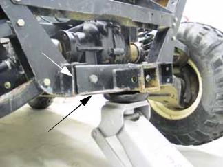
The front of the vehicle may be safely lifted by placing a jack directly under the mounting point where the front differential joins the frame. See Figure 1.7.
Figure 1.7
Figure 1.8
Alternatively, the vehicle may be lifted by positioning a jack along the outer frame channel, where the rear out-rigger extends to meet the base of the OPS .
See Figure 1.9.
Figure 1.9
NOTE: The center of gravity for the vehicle is beneath the seat support structure.
NOTE: The outer frame channel will support the vehicle without damage.
4

5.DRIVE SYSTEM DESCRIPTION
•A belt-type CVT (Continuously Variable Transmission) system carries power from the engine crankshaft to the transfer case.
See Figure 1.10.
CVT driven element
CVT belt

CVT driving element
Figure 1.10
•The CVT range provides strong torque and acceleration, limiting speed to 25 MPH (40 KPH).
•The driving clutch on the engine crankshaft uses centrifugal force to operate a mechanism that pulls the sheaves closer together.
The faster the engine spins, the closer the sheaves get.
As the sheaves close-down on the belt, the belt is forced outward.
As the belt is forced outward, the drive ratio decreases so that fewer crankshaft revolutions equate to more input shaft revolutions at the input shaft of the transfer case.
NOTE: A lower numeric ratio results is frequently referred to as a “steeper” or “taller” drive ratio, yielding in increased top speed.
•As the effective diameter of the driving pulley increases, the belt has less available length to reach the driven pulley.
The sheaves of the driven pulley is springloaded so that it can absorb the additional tension.
An additional effect is that the belt is drawn deeper into the sheaves, reducing the effective diameter of the driven pulley.
Reducing the diameter of the driven pulley further reduces the drive ratio.
Chapter 1: Introduction
•The transfer case is mounted adjacent to the engine, with the input shaft running fore-and-aft in the frame. See Figure 1.11.
Transfer case

Figure 1.11
•The transfer case contains two forward ratios, neutral, and reveres.
•Gear selection is controlled by rods and a selector lever sourced from Hurst®.
Drive shafts with Hooke/Spicer type universal joints extend fore and aft from the output shafts of the transfer case to drive the front and rear differentials.
The rear differential has a cast iron housing and a cable-actuated locking feature. See Figure 1.12.
Differential lock
actuator
Rear differential
Figure 1.12
5

Chapter 1: Introduction
The front differential has an aluminum housing, and an electronically controlled, slip sensing Auto-Lok® feature. See Figure 1.13.
Front differential |
Electrical connection for |
|
|
|
Auto-Lok® feature |
Figure 1.13
•The front differential is engaged or disengaged using a rocker switch on the dashboard.
Each differential transfers power to the drive hubs through a drive shaft with Rzeppa-type constant velocity joints at each end.
6.SERVICE INTENT
The transfer case is manufactured by Cub Cadet. If it fails during the first year, it should be removed and replaced as a complete unit.
•In the event of a failure, the transfer case will be called back for engineering analysis.
•If the failure is warrantable, Cub Cadet will cover the cost of replacement.
•If the failure is not warrantable, replacement will be at the customer’s expense.
•Beyond the first year, but within the first two years, the decision whether to repair or replace the transfer case will be based on economic feasibility and the availability of parts and assemblies.
•Beyond the warranty period, the dealer can repair or replace the transfer case at their own discretion.
The remainder of the drive system (CVT, drive shafts, axles, differentials) is purchased from outside vendors.
•If any of these items fail in the first two years, they should be removed and replaced with a complete unit. The only exception to this may be the axles. Rzeppa (Constant Velocity) joints may be available to repair rather than replace axles. Service intent has not been decided as this manual goes to print.
•In the event of a failure, the component will be called back for engineering analysis and vendor recovery.
•If the failure is warrantable, Cub Cadet will cover the cost of replacement.
•If the failure is not warrantable, replacement will be at the customer’s expense.
•Beyond the warranty period, internal parts for the differentials will be made available so that the dealer can repair or replace them at their own discretion.
Kohler Engines will be serviced as they are in the rest of the Cub Cadet product Line. They are seen as an integral part of the Cub cadet product, with parts and warranty coverage provided through Cub Cadet.
Caterpillar Engines in Cub cadet equipment will continue to be serviced exclusively by CAT dealers.
6
7.SPECIAL TOOLS
NOTE: There are many specialized tools that will make servicing the Cub Cadet 4X4 easier. There are only a couple of tools that are not likely to be in a technician’s normal tool assortment that necessary to service the 4X4.
7.1.A small metric screw (6m/1.0) (size/thread pitch) having a minimum thread length of 1.15” (2.9cm) can be used to spread the sheaves of the driven clutch. This is necessary if the belt is to be replaced without removing both pulleys. The screw can be purchased locally and modified using a thread die. See Figure 1.14.
Chapter 1: Introduction
7.3.A pulley alignment tool should be used to check the alignment of the drive pulley and driven pulley after any procedure that may have disturbed the alignment, or if unusual belt wear occurs.
See Figure 1.16.
Alignment tool
P/N: 707-04878 
Figure 1.16
Figure 1.14
7.2.The second tool that is necessary to service the drive system is a puller that draws the driving clutch off of the engine crankshaft.
See Figure 1.15.
Driving pulley removal tool:
Part number: 759-04111
Figure 1.15
7
Chapter 1: Introduction
8

Chapter 2- Drive System: CVT and Transfer Case
CHAPTER 2- DRIVE SYSTEM: CVT AND TRANSFER CASE
DRIVE SYSTEM: SERVICE INTENT
1.The transfer case is manufactured by Cub Cadet. If it fails during the first two years, it should be removed and replaced as a complete unit.
•In the event of a failure, the transfer case will be called back for engineering analysis.
•If the failure is warrantable, Cub Cadet will cover the cost of replacement.
•If the failure is not warrantable, replacement will be at the customer’s expense.
•Beyond the warranty period, internal parts will be made available so that the dealer can repair or replace the transfer case at their own discretion.
2.The remainder of the drive system (CVT, drive shafts, axles, differentials) is purchased from outside vendors.
•If any of these items fail in the first two years, they should be removed and replaced with a complete unit.
•In the event of a failure, the component will be called back for engineering analysis and vendor recovery.
•If the failure is warrantable, Cub Cadet will cover the cost of replacement.
•If the failure is not warrantable, replacement will be at the customer’s expense.
•Drive system components other than the CVT and transfer case are covered in greater depth in the Drive shafts, Axles, and Differentials chapter of this manual.
CVT AND TRANSFER CASE OPERATION
1.The transfer case contains a relatively conventional three-shaft gear-set providing Neutral, Reverse, Forward, and Forward Low-range.
2.The variation in drive speed within each gear is created by a combination of engine RPM and a CVT belt drive system.
3.The CVT belt drive system consists of : See Figure 2.1.
•Driving element = driving pulley = centrifugal torque converter mounted to the crankshaft.
•Driven element = driven pulley = pulley sheaves mounted to the input shaft of the transfer case that react to the motion of the driving element.
•A special belt that transfers power from the driving element to the driven element.
Driving element |
Driven element |
Belt
Figure 2.1
4.Common parts:
4a. The belt and driven element are the same on both models of the current Cub Cadet 4X4.
4b. The driving elements are different for gas and diesel versions. The gas engine and diesel engines have different torque curves and maximum operating speeds.
9

Chapter 2- Drive System: CVT and Transfer Case
4c. The driving elements are tuned to get the best vehicle performance out of each model engine, taking into account: engine power band and top speed, vehicle weight, maximized vehicle pulling power, maximized vehicle acceleration, and a 25 MPH (40 KPH) maximum speed.
5.Operation:
5a. At rest (engine OFF or at low idle) the sheaves of the driving element (on the engine crankshaft) are at the widest point of their travel. The belt rests on a central bearing surface, but no significant power is transmitted to the driven element at idle speed. See Figure 2.2.
Low idle speed
Driving element released (spread)
Figure 2.2
5b. At about 1,400 RPM, the sheaves move closer to each-other. As they do, they touch the sides of the belt and begin to transmit power. See Figure 2.3.
Low RPM: Driving element
beginning to engage belt Belt deep in sheave 
Figure 2.3
•The sheaves are moved by fly-weights within the driving element housing. Centrifugal force drives the fly-weights out. The fly-weights are levered against the sheave, forcing it inward.
5c. As the engine RPMs increase, the sheaves close further, forcing the belt outward on the sheaves. See Figure 2.4.
Moderate engine speed
Driving pulley partially closed-down
Belt partially shifted-out
Figure 2.4
10

Chapter 2- Drive System: CVT and Transfer Case
•The further the drive point (contact patch between the belt and the sheaves) is from the crankshaft, the greater the effective circumference of the driving pulley (element).
•The greater the effective circumference of the driving pulley, the more linear motion is transferred to the belt for each crankshaft revolution.
•This increases the drive speed, but reduces the amount of torque the engine transfers to the drive system.
•If the engine is over-loaded by a combination of grade and cargo weight while operating at full throttle, the RPMs will be pulled-down. As the engine RPMs are reduced, the drive ratio will automatically shift in the numerically higher direction, increasing the amount of torque available to the wheels, at the expense of ground speed.
5d. As the belt is forced outward on the sheaves of the driving element, the driven element spread allowing the belt to be drawn deeper-in. See Figure 2.5.
|
Driven pulley at speed |
Sheaves |
Belt deep in sheaves |
|
|
|
Belt |
Figure 2.5
5e. As the belt is drawn deeper into the driven pulley, two things are accomplished:
•Belt tension is held constant, even though the effective size of the driving pulley changes.
•The range of available drive ratios is widened.
5f. At about 3,000 RPM (Kohler) or 2,500 RPM (Caterpillar) the driving element reaches the end of its travel.
See Figure 2.6.
Driven element fully drawn together: Belt at outer
edge
Figure 2.6
•Any increase in vehicle speed beyond the end of CVT travel is due only to an increase in engine speed. The rate of vehicle acceleration will level-off.
IDLE SPEED AND TOP NO-LOAD SPEED
1.The Kohler and CAT engines should idle at 1,200 RPM. See Figure 2.7.
Belt still
Sheaves
spread 

 Clutch spinning at idle speed
Figure 2.7
11

Chapter 2- Drive System: CVT and Transfer Case
•Slower idle speeds will result in poor idle quality, reduced flow of cooling air, and reduced oil flow.
•Higher idle speeds will result in harsh gear selector action and possible internal damage to the transfer case.
2.Top no-load speed should be 3,600 RPM for the Caterpillar and 3,850 RPM for the Kohler:
See Figure 2.8.
Sheaves |
Belt spinning |
|
closed |
||
|
Engine at max. RPM
Figure 2.8
•Slower top no-load speeds will result in diminished performance.
•Higher top no-load speeds will result in unsafe operating conditions and possible over-speed engine failure.
3.If the idle speed and top-no-load speed do not fall into this range, refer to the appropriate engine chapter for adjustment procedures
•Caterpillar related systems Chapter 8
•Kohler engine service access and fuel system Chapter 7
DRIVE SYSTEM SERVICE ACCESS, SAFETY, AND TIPS
1.When working on the belt, block the wheels to prevent the UV from rolling.
2.Place the transmission in neutral.
3.When working on any components (like the CVT) that rotate with the engine, disable the engine:
3a. Disconnect and ground the spark plug wires on a gasoline engine.
3b. Unplug the fuel shut-off solenoid on a diesel engine.
3c. Remove the key from the key switch.
3d. Preferably, disconnect the ground cable from the negative terminal of the battery.
4.Unless a procedure specifically requires the engine to be running, the engine should be turned-off for all maintenance, adjustments, and repair.
5.To reach the CVT, fold the seats forward and secure them with shock cords. Release the Camloc® fasteners and lift the parcel bin out from beneath the driver’s seat
6.Once accessed, the driving element, the driven element, and the belt can be removed. There are some simple but specialized tools required to loosen the belt and remove the driving element
•A small screw can be used to spread the sheaves of the driven element so that the belt can be removed. Specific dimensions are given in the belt removal section of this chapter.
•A clutch puller is needed to pull the driving element off of the tapered crankshaft.
NOTE: The belt may be removed independently, or the CVT may be removed complete with the belt.
12
Chapter 2- Drive System: CVT and Transfer Case
DRIVE SYSTEM ADJUSTMENTS:
1.CVT spacing and alignment:
•Spacing and alignment are critical to proper CVT performance and belt longevity.
•In normal service, these items should not be an issue on this vehicle. The engine and transfer case are firmly tied to each-other by the engine / transmission plate that holds proper spacing and alignment.
2.Adjustment of the driving element and driven element:
•The CVT is tuned to maximize performance of the vehicle. It should require no adjustment in its normal service life.
•While it is mechanically possible to disassemble the driving and driven elements, individual parts will not be available through Cub Cadet.
CVT SERVICE
1.BELT REMOVAL
NOTE: The procedure to remove the belt is the same for the Kohler and the Caterpillar engines.
1a. When new, the belt measures 1.335” +.031” (33.9 + .8mm) across the wide flat outside surface of the belt. The belt is considered worn when the measurement is 1.20” (30.5mm) or less. some degradation of performance may begin to occur as belt is worn to less than 1.275” (32.4mm). See Figure 2.9.
New: 1.335” (33.9mm)
Worn: 1.20” (30.5mm)
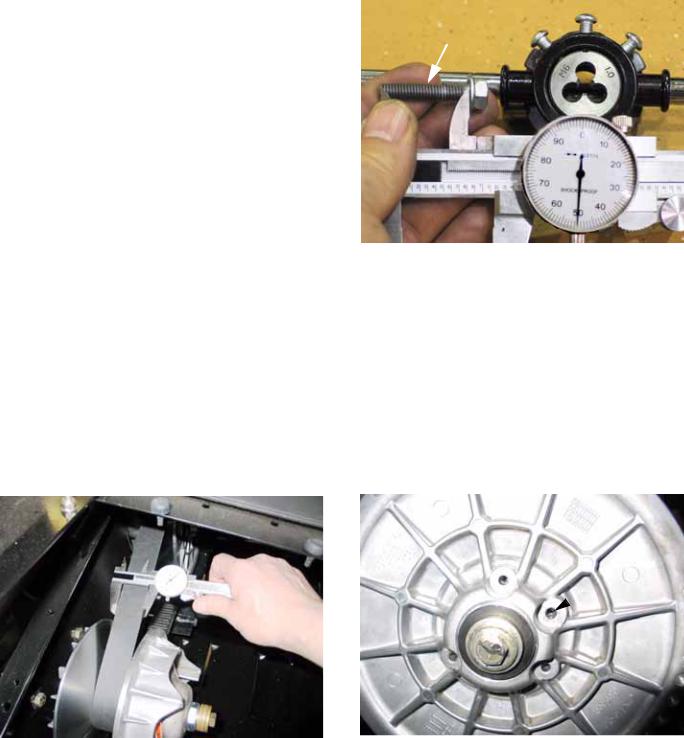
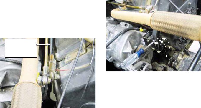
1b. To remove the belt, a 6mm/1.0 screw with a minimum thread length of 1.15" (2.9cm) will be required. See Figure 2.10.
1.15” (2.9cm) thread length
Figure 2.10
NOTE: A 6mm screw with a thread pitch of 1.0 may be purchased locally. The minimum thread length needed is longer than the threads of a standard screw of this size. It will be necessary to cut threads further up the shank of the screw using a thread-cutting die.
1c. There are 4 holes in the face of the driven element. Three of them are close together, one is 180 degrees away from the others. The middle hole of the set of three is threaded.
See Figure 2.11.
 Tapped hole
Figure 2.9 |
Figure 2.11 |
13
Chapter 2- Drive System: CVT and Transfer Case
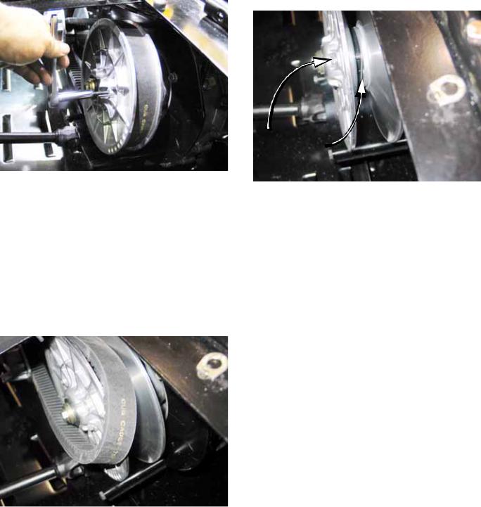
1d. Thread the screw into the tapped hole in the outer half of the driven element sheave. The end of the screw will press against the inner half of the sheave, spreading the two apart. See Figure 2.12.
NOTE: On the Caterpillar engines, The belt may be harder to roll off the sheave, but it will roll off.
1f. The belt can easily be installed by reversing the removal process. See Figure 2.14.
Figure 2.12
NOTE: It is common practice among snowmobilers to carry a spare belt. Belt life on this vehicle should not be an issue, but if the utility vehicle is operated in very remote areas, it may provide some peace-of-mind for the operator. If they choose to carry a spare belt, a suitable screw and a 10mm wrench should be kept with it.
1e. As the sheaves are spread, the tension on the belt will be relieved, and the belt can be rolled-off of the driven element (pulley). See Figure 2.13.
Figure 2.13
Screw maintains distance between sheaves
Figure 2.14
NOTE: When the belt is installed, remove the screw before operating the vehicle
NOTE: It may be necessary to start the vehicle, , and rev the engine in neutral to seat the belt.
2.Removal of the Driving element
NOTE: The driving element is most easily removed after the belt is taken-off.
NOTE: The driving element can be removed with the belt in place, but installation may require the driven element sheaves to be spread unless all three parts of the CVT are installed together, as described later in this section.
NOTE: The bolt that holds the driving element to the crankshaft can be reached by removing the plastic cap from the end of the driving element.
If the driving element spins the crankshaft when the tool is tightened it will be necessary to hold the CVT or lock the crankshaft. One means of holding the CVT involves removing the cover. That is the technique described in this section.
2a. Disconnect and ground the spark plug leads (Kohler) or un-plug the fuel shut-off solenoid (Caterpillar).
14
Chapter 2- Drive System: CVT and Transfer Case
2b. Remove the three screws holding the coverinplace,thenremovethecover. See Figure 2.15.
Driving element cover
Screws

Plastic cap
Figure 2.15
2c. Hold the large nut with a 30mm wrench while loosening the crankshaft bolt with a 5/8” wrench.
2d. Withdraw the bolt, washers, and shoulder spacer. See Figure 2.16.
Nut
Flat washer(s) Shoulder washer
Driving element
Figure 2.16
3.Install the clutch removal tool (M14 - 2.O) by threading it into the clutch, pressing against the crankshaft.
3a. Hold the pulley with a 30mm wrench, and turn the tool using a 22mm wrench. This will force the driving element off of the crankshaft. See Figure 2.17.
Inset: clutch tool
One wrench to turn the tool 
One wrench to hold the clutch
Figure 2.17
CAUTION: There is a tapered fit between the driving element and the crankshaft. Applying force to the perimeter of the driving element will break it.
3b. If the belt was not previously removed, it can be taken-off as the driving element is removed.
4.Removal of the driven element 4a. Remove the belt.
NOTE: The driving element fits on a tapered shaft. It can be removed with the belt in-place because the tapered shaft provides freedom of movement as soon as the driving element comes loose.
The driven element fits on a splined shaft. As the driven element is drawn off the shaft, the belt will tighten, making removal difficult even with the sheaves spread. The belt should be removed before taking-off the driven element.
15

Chapter 2- Drive System: CVT and Transfer Case
4b. Place the transfer case in H position, and set the parking brake.
4c. Loosen the bolt that holds the driven element to the input shaft using a 9/16” wrench.
NOTE: Hold the driven element from rotating using a pin spanner, if needed.
4d. Remove the bolt and washers. See Figure 2.18.
Figure 2.18
4e. At this point, the driven element may be slipped off of the transfer case input shaft.
5.CVT Installation
NOTE: The driving element and driven element can be installed individually, then the belt can be rolled-on as described in the belt removal section of this chapter.
Alternatively, both elements and the belt can be installed all-at-once using a simple wood-block tool. This method is described in the following steps.
Preparation and torque specs remain the same for both methods.
6.Make the wood block spacer as described in the accompanying illustration. See Figure 2.19.
|
3-1/2” (8.9CM) |
4-3/8” |
5-1/8” |
(13.1CM) |
|
(8.6CM) |
|
NOTE: BLOCK ENDS MAY BE |
|
V-SHAPED OR CURVED |
|
|
Figure 2.19 |
6a. Prepare the CVT for installation: See Figure 2.20.
•Clean the shafts and the surrounding area before installing the CVT.
•Confirm the presence of the .060” (1.5mm) spacer on the shaft between the driven element and the transfer case housing.
•A small amount of anti-seize compound may be used on the splined joint between the input shaft of the transfer case and the driven element.
•The tapered joint between the driving element and the crankshaft must be clean and dry.
Tapered shaft
Spacer
Splined shaft
Figure 2.20
16
Chapter 2- Drive System: CVT and Transfer Case
6b. Install the belt around the pulleys and insert |
6f. Secure the driven element to the input shaft |
the wood block tool between the pulleys |
using the bolt, washer, and shoulder |
to establish correct spacing. |
spacer previously removed. Do not |
See Figure 2.21. |
tighten fully at this time. See Figure 2.23. |
Wooden tool sets |
|
spacing and holds |
|
assembly together |
|
for installation |
|
CVT installed all at once
Figure 2.21
6c. Install the belt and pulleys, with the wood block between them, onto the crankshaft of the engine and the input shaft of the transfer case.
6d. Apply a small amount of thread locking compound such as Loctite® 262 (red) to the bolts that secure each pulley.
6e. Secure the driving element to the crankshaft using the bolt, washers, and shoulder spacer previously removed. Do not tighten fully at this time. See Figure 2.22.
Shoulder spacer
Washers
 Bolt
Bolt
Figure 2.23
6g. Tighten the bolts securing the pulleys to their respective shafts in even steps, drawing the pulleys into place.
6h. Once seated, tighten the bolts to the specified torque:
Item |
ft-lbs |
N-m |
|
|
|
|
|
|
Driving element to |
32-36** |
43-49** |
engine crankshaft |
|
|
|
|
|
Driven element to |
70-80** |
95- |
transfer case input |
|
109** |
shaft |
|
|
|
|
|
** Install with permanent thread locking compound such as Loctite® 262 (red).

 Driving element
Figure 2.22
17

Chapter 2- Drive System: CVT and Transfer Case
6i. Remove the wood block tool. |
DRIVE SYSTEM ADJUSTMENTS: |
See Figure 2.24. |
TRANSFER CASE SHIFT LINKAGE |
Tighten bolts and remove
block
1.Before attempting any linkage repair of adjustment, confirm whether the problem at hand is in the linkage or elsewhere in the system.
2.A handy quick-check to confirm that the transfer case is in neutral when the gear selector is in neutral can be made using the two safety switches in the starter circuit: See Figure 2.25.
Switch harness unplugged
Figure 2.24
6j. Test the operation of the drive system in a safe area, then allow the exhaust system to cool before final assembly.
6k. Final assembly: install the cover and plug on the driving element and replace the parcel bin under the passenger’s seat.
Both switches in series: contacts closed
Figure 2.25
2a. Locate and disconnect the harness that leads to the neutral safety switches.
2b. Connect a DVOM or continuity light to the pair of terminals on the disconnected harness.
2c. When the transfer case is in neutral, there should be continuity (0.0 Ω) between the two wires in the terminal.
NOTE: There are two sets of shift forks within the transfer case. Each shift fork has a safety switch associated with it. When both shift forks are in the neutral position, the contacts of both switches will be closed. The switches are connected in series, so the closure of both switches completes the circuit.
3.The correct operation of the switch can be confirmed by rotating the transfer case input shaft and observing the reaction of the output shafts.
4.After correct internal operation of the transfer case is confirmed, check the linkage. Correct any internal problems before proceeding. If the transfer case has internal damage, no amount of external adjustment will fix it.
18
Chapter 2- Drive System: CVT and Transfer Case
NOTE: Methodology: start at the source (the transfer case), and work toward the control input (the gear selector).
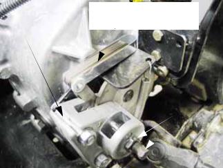
5.Operate the gear selector through its full range of motion (high range forward, low range forward, neutral, and reverse). Look for the following issues: See Figure 2.26.
Forward-Neutral-
Reverse rod
Low-range rod 
Figure 2.26
•Lost motion
•Loose hardware
•Mechanical interference
•Unintended bends in the linkage
•Excessive linkage bowing under load
•Engagement of the gear that is selected
6.Correct any of these initial problems before proceding with adjustment.
NOTE: It is possible to make a damaged linkage work better by compensating for the damage with adjustment. This should not be considered complete repair.
7.Centering the linkage: See Figure 2.27.
Neutral  alignment holes
Figure 2.27
7a. With the linkage disconnected, the shift forks are centered in the neutral position by detent springs.
7b. At this point the shift arms can be locked into the neutral position by inserting a 3/ 16” (or 5mm) dowel rod through the alignment holes in the shift lever bracket and shift arms located on the back of the transfer case housing.
7c. The center-point of neutral position at the Hurst gear selector lever corresponds with the center of the range where the shift lever can move from the high-neutral- reverse gait into the neutral-low gait.
7d. Find the point were the Hurst lever moves left and right between the two gates. This is the center-point of it’s range of travel.
19

Chapter 2- Drive System: CVT and Transfer Case
8.Rod adjustment is made by lengthening or shortening the shift rods to make neutral at the Hurst gear selector lever correspond with neutral within the transfer case. See Figure 2.28.
Disconnecting linkage
to make low-range adjustment
Figure 2.28
8a. The heavier rod that is connected to the shift arm nearest the engine controls forward (high range), neutral, and reverse functions.
8b. Loosen the jam nut, then disconnect the rod to adjust it using a pair of 9/16” wrenches.
8c. Thread the rod-end up or down the length of the threads for adjustment.
8d. The lighter rod that is connected to the shift arm farthest from the engine shifts the transfer case between neutral and low range forward.
8e. Loosen the jam nut using a 1/2” wrench and a 7/16” wrench, then disconnect the transfer case end of the rod using a pair of 1/2” wrenches.
9.Snug the jam nuts and remove the locking dowel after rod adjustment is completed.
10.After the rod adjustment is done, operate the linkage to confirm that the shift forks move fully to their engaged detent positions.
•If there is insufficient travel, the stops on the Hurst shift mechanism can be moved out.
•If the linkages are over-throwing the shift fork travel, the stops on the Hurst shift mechanism can be moved in.
•The stops are unlikely to need adjustment in the normal service life of the utility vehicle. The most likely reason for the stops to be out of adjustment would be tampering by unqualified technicians.
10.1.Remove the console cover / cup holder to gain access to the stop adjustments.
See Figure 2.29.
Hurst shift  linkage exposed
Console cover / cup holder  removed
Figure 2.29
10b. Remove the knob from the Hurst gear shift by turning it counter-clockwise.
10c. Remove the grip from the differential lock control lever by pulling upward from the base of the grip. A blow gun may be used to force the grip off of the lever by shooting compressed air into the hole at the top of the grip while lifting upward.
20

Chapter 2- Drive System: CVT and Transfer Case
10d. Unbolt the console cover / cup holder using a 9/16” wrench to remove the two screws that hold the back of the console cover. A 9/16” wrench can also be used to loosen the two screws that secure the front edge of the cover through slotted holes.
10e. Lift the cover off to remove it.
11.Push the Hurst lever straight forward to engage high-range forward gear.
12.Pulling gently back on the lever to take-up play in the linkage, there should be 1/16” (1.5mm) of clearance between the lever and the tip of the forward stop bolt (mounted at the rear of the mechanism).
NOTE: A 1/16” or 1.5mm allen wrench makes a suitable feeler gauge, positioned so that the flats (not the peaks) are spanning the gap between the stop bolt and the lever.
NOTE: Do not adjust the travel to make-up for out-of adjustment shift rods. Travel stop adjustment is merely for confirmation and is not likely to need adjustment in the normal life of the vehicle.
13.If adjustment is necessary, loosen the jam nut and tighten or loosen the bolt using a 9/16” wrench. See Figure 2.30.
14.When adjustment is complete: 14a. Snug the jam nut.
14b. Move the lever into reverse
14c. Repeat the adjustment in the opposite direction on the reverse stop bolt.
15.Test the operation of the drive system in safe area. Confirm that:
15a. The vehicle does not try to move in neutral
15b. The gear selector lever works smoothly and easily, providing solid “feel” for each gear.
15c. Each gear engages fully. A partially engaged gear may “jump out” when power is applied.
NOTE: Other mechanical causes may cause the vehicle to jump out of gear, e.g.: worn or missing detent spring, damaged shift fork, damaged shift dogs. Of those issues, only the detent balls and springs can be reached without removing the transfer case from the vehicle.
16.Install the console cover / cup holder, gear selector knob, and rear differential lock control lever grip.
Shift linkage  travel stop adjustment
Figure 2.30
21
Chapter 2- Drive System: CVT and Transfer Case
DRIVE SYSTEM ADJUSTMENT: PARKING BRAKE
NOTE: The parking brake is mounted to the transfer case, and its operation is completely independent of the hydraulic service brakes.
1.The parking brake has two functions:
1a. It should prevent the vehicle from rolling when it is applied.
1b. It should not drag when released.
2.Parking brake operation should be checked at each oil change interval. If the operator notices any change in operation of the parking brake, it should be checked before any further use.
NOTE: When the engine is turned-off, the CVT will not stop the vehicle from rolling, even if the transfer case is left in gear. The parking brake is essential to safe operation of the vehicle.
3.Visual inspection of the brake system should accompany adjustment. Look for:
•Indications of dragging brake:
-burning smell
-discolored park brake rotor
-sluggish performance
-accelerated brake pad wear
-slack cable when brake is released.
•Indications of impending failure
-corroded or frayed cable
-excessive travel on park brake lever before
-brakes engage
-worn brake pads: < .030” friction material thick ness (< .762mm)
-burnt, kinked, or chafed cable housing
-loose hardware or damaged brackets
-mechanical damage to rotor or caliper
4.Repair any of these issues before proceeding with adjustment. Adjustment should be checked after any service to the parking brake caliper of linkage.
5.Checking caliper adjustment: See Figure 2.31.
|
Feeler gauge |
Parking brake |
.010-.013 (.254-.330mm) |
caliper |
|
|
Adjustment screw and jam nut
Figure 2.31
5a. Chock the wheels so that the vehicle will not roll.
5b. Release the parking brake.
5c. Confirm that the return spring has drawn the arm on the caliper all the way against the stop.
5d. Use a feeler gauge to check the clearance between the parking brake rotor and one of the pads. It may be necessary to wiggle the rotor slightly, forcing the pads back from the rotor.
5e. Clearance should be between .010” and
.013” (.254mm-.330mm).
5f. Adjust the caliper if it is not in this range.
22

Chapter 2- Drive System: CVT and Transfer Case
6.The caliper can be adjusted using the screw and jam nut on the caliper. Us a 7/16” wrench and an 11/16” wrench. See Figure 2.32.
Park brake caliper adjustment
Figure 2.32
6.1.After the caliper is in correct adjustment, the linkage that operates it can be adjusted properly.
6.2.The parking brake lever pulls on the cable to engage the brake when the lever is pulled upward. See Figure 2.33.
Park brake lever
in released position
Park brake
 switch
Park brake cable
Figure 2.33
•It moves up in steps that correspond to notches in a lock plate that the brake lock passes over in its travel. Full travel = 5 notches.
•There is a park brake switch mounted beneath the lever. The contacts within the switch are normally closed. As the lever is pulled-up, the plunger extends from the switch, closing the contacts.
•Contact closure = 2 notches.
7.Correct adjustment results in full engagement of the parking brake before the 5th notch, but allows the lever to come up far enough to close the contacts in the switch.
8.Checking adjustment: See Figure 2.34.
Park brake light
Figure 2.34
8a. Make the adjustment with the key switch turned on, but the engine not running, and the wheels chocked.
8b. Release and reapply the parking brake.
8c. As the bake lever passes the second notch, the brake light on the instrument cluster should illuminate. If the transfer case is not in neutral, an alarm should sound as well. At this point the slack should be out of the parking brake cable, and the arm on the caliper just beginning to move.
9.By the third notch, drag should be noted when the drive shaft leading to the rear differential is turned.
23

Chapter 2- Drive System: CVT and Transfer Case
10.By the fourth notch, it should be impossible to rotate the drive shaft. See Figure 2.35.
Correct adjustment =
fourth “click” on handle +
 tight cable +
brake fully engaged
Figure 2.35
11.1.Adjustment can be made using a pair of 1/2” wrenches at the anchor point of either end of the cable. See Figure 2.37.
Adjustment at caliper end of cable
Figure 2.37
11.To reach the adjustment point for the parking brake, release the CamlocR fasteners and remove the parcel bin that is located beneath the driver’s seat. See Figure 2.36.
Parcel bin
CamlocR  fasteners
Figure 2.36
CAUTION: Make sure the cover is firmly in place on the positive battery terminal before adjusting the cable. Contact between a wrench and the terminal can short out the battery, causing potential injury from heat burns, chemical burns, and battery explosion.
12.Lock the adjustment by snugging the jam nut against the mounting bracket.
13.Test the operation of the parking brake in a safe area before returning the vehicle to service. It should remain stationary with a full load on a 15 degree slope with the parking brake engaged.
NOTE: While this is an extremely capable vehicle, 15 degrees is the maximum angle of operation specified in the Operator’s Manual.
24

Chapter 2- Drive System: CVT and Transfer Case
DRIVE SYSTEM SERVICE: LUBRICATION
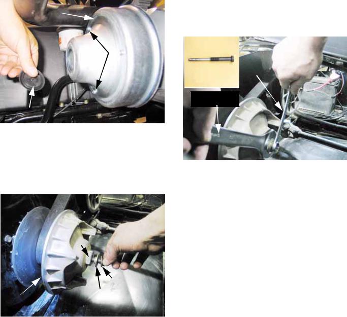
1.The universal joints in the drive shafts that connect the transfer case to the front and rear differentials are lubricated on assembly, and should not need further lubrication in their normal service life. See Figure 2.38.
Figure 2.38
2.The constant velocity (Rzeppa type) joints in the axle shafts that drive the wheels are lubricated on assembly, and should need no further lubrication in their normal service life.
See Figure 2.39.
Figure 2.39
NOTE: Grease is contained in the constant velocity joint boots. If a boot is damaged, the grease will get contaminated. Once the grease is contaminated, accelerated wear and joint failure will occur. Replace any damaged boot as soon as possible. Clean and inspect the boots regularly.
3.The transfer case contains 64 fl.oz. (1.9 l.) of 80W-90 Low Foam Oil (Cub Cadet P/N: 73704040). See Figure 2.40.
 Vent
Vent
Fill plug
Figure 2.40
•The transfer case oil should be changed after the first 5 hrs. of use, 50 hrs. of use, and at 500 hr. intervals thereafter.
•Inspect the transfer case vent at 100 hr. intervals. A blocked vent will cause fluid loss.
•The transfer case gear lube should be checked at 100 hr. intervals, or more frequently if fluid loss is noticed.
•In the event of fluid loss, identify and repair the leak as soon as possible to prevent catastrophic failure of the transfer case, disabling the vehicle.
4.To check the fluid in the transfer case: See Figure 2.41.
Transfer case level plug 
Figure 2.41
25

Chapter 2- Drive System: CVT and Transfer Case
5.13.4. Transfer case, continued...
5a. Park the vehicle on a firm level surface.
5b. Allow the engine and drive system to cool to ambient temperature.
5c. Tilt the cargo box up.
5d. Release the CamlocR fasteners and lift away the engine cover.
5e. Clean the area surrounding the fill plug and level plug.
5f. Remove the level plug using a 5/8” wrench, and check for the presence of fluid at a level even with the bottom of the threads.
5g. Clean the plug and inspect the o-ring seal. Replace the o-ring if it is suspect.
6.If the fluid level is low, gear lube may be added through the fill plug near the top of the transfer case housing. See Figure 2.42.
Fill plug 
Level plug
6a. The fill plug can be removed with a 5/8” open-end wrench.
6b. Inspect the gear lube for debris or metal chafe, then dispose of it properly.
6c. Add gear lube until it begins to dribble out of the level plug hole.
6d. Replace the fill and level plugs. Snug the fill plug, and tighten the level plug to at torque of 10 ft-lbs. (13.5 N-m).
6e. Replace the engine cover.
7.To change the lube in the transfer case, follow the guidelines for checking the fluid. The case may be drained of lube by removing the plug using a 5/8” wrench. See Figure 2.43.
Inset: drain plug
O-ring seal
Drain plug access from beneath vehicle
Figure 2.43
Figure 2.42
26
Loading...