


CDG2000FW0
Crosley CDG2000FW0, FGR6600FS0, GCGR1042FS0, GLER1042FC0, GCER1042FC0 Installation Instructions Manual
...
In
Instructions
Instructions
Before beginning installation, carefully read these instructions. This
wilt simplify the installation and ensure the dryer is installed correctly
and safely. Leave these instructions near the Dryer after installation
for future reference.
NOTE: The electrical service to the Dryer must conform with local
codes and ordinances and the latest edition of the National Electrical
Code, ANSI/NFPA 70 or in Canada, CSA C22.1 Canadian Electrical Code
Part 1.
NOTE: The gas service to the Dryer must conform with local codes and
ordinances and the la test edition of the National Fuel Gas Code ANSI
Z223.1 orin Canada, CAN/CGA B149.12.
NOTE: The Dryer is designed under ANSI Z 21.5.1 or ANSI/UL 2158 -
CAN/CSA C22.2 No. 112 (latest editions) for HOME USE only. This
Dryer is not recommended for commercial applications such as
resta urants or beauty salons, etc.
Avant de commencer, lire attentivement le present document. Cela
simplifiera t'installation et assurera la pose correcte et s_curitaire de
la secheuse. Apr_s I'installation, laisser ce document &proximit_ de
la secheuse pour reference future.
REMARQ UE : L'alimenta tion electrique de la secheuse dolt respecter
les codes et ordonnances toca ux ainsi que I"edition la plus recente du
Code ANSI/NFPA 70, ou au Canada, te Code canadien d'_lectridte,
A CNOR C22.1, parde l.
REMARQUE : L"alimentation en gaz de la secheuse dolt respecter fes
codes et ordonnances Iocaux ainsi que I"edition la plus recente du Code
ANSI Z223.1, ou au Canada, le code CAN/A CG B 14g. 12.
REMAROUE : La secbeuse est tongue conformement au code ANSI Z
21.5.1 ou ANSI/UL 2158 - CAN/ACG C22.2 No. 112 (Fedition la plus
recente) pour un USA GE DOMESTIQUE seulement. Cette secbeuse n 'est
pas recommandee pour udlisa don commerciale, comme par ex emple
un testa urant ou un salon de coiffure, etc.
Antes de comenzar la instafaci6n, lea cuidadosamente estas
instrucciones. Esto simplificar4 la instalaci6n y asegurar4 que la secadora
se instale correctamente y de manera segura. Despu_s de completar la
instalad6n, coloque estas instrucciones cerca de la secadora para
referencia futura.
NO TA: La alimentaci6n electrica para la secadora deber2 cum plir con los
c6d_gos y reglamentos locates y con ta ultima edici6n del Cbd@o Electric o
National, ANSI/NFPA 70 o en Canad_ CSA C22.1 C6digo Electrico
Canadiense, Parte 1.
NO TA: La alimentad6n de gas para la secadora deber_ cumplir con los
c6digos y reglamentos focales y con la uldma edici6n del C6digo Nacional
para Gases Combustibles, ANSI Z223.1 o en Canad2 CAN/CGA B 149.12.
NO TA: La secadora est2 dasificada para USO DOMESTICO solamente,
deacuerdoconlanormaANSIZ21.5.1 oANSI/UL2158-CAN/CSA C22.2
No. 112 (las Oltimas edid6nes). Esta secadora no se recomienda para
uso commercial tal como en restaurantes, salones de belleza, etc.
Printed in U,S,A
For your safety the information in this manual must be followed
to minimize the risk of fire or explosion or to prevent property damage,
personal injury or loss of life.
- Do not s_ore or use gasoline or other flammable vapors and liquid in the
vicirfity of this or any other appliance.
° WHAT TO DO IF YOU SMELL GAS
. Do not try to light any appliance
. Do no_ touch any electrical switch; do not use any phone in your
building,
. Clear the room, building or area ol all occupants.
. Imrnedia_ely call your gas supplier from a neighbor's phone, Follow
the gas supplier's instructions,
• If you cannot reach your gas supplier, call the fire department.
Installations must be perlormed by a qualified or licensed contractor,
plumber, or gasfitter qualified or licensed by the s_ate, province, or region
where this appliance is being installed.
le present guide afin de m n m ser les r sques d'incendie, d'explosion, de
dommages mat@iels, de blessures et de mort.
Ne pas en_reposer ni utiliser d'essence ou d'autres vapeurs ou liquides
inflammables _ proximitd, de cette secheuse ou de tout autre appareil
d,lectrom_'mager,
QUE FAIRE S'IL Y A UNE ODEUR DE GAZ
N'allumer aucun appareil _k_trique.
Ne toucher aucun commuta_eur #,lectrique; ne pas utiliser le
t#,l_,phone dans I'immeuble.
Faire sortir tousles occupants de la pi¢,ce, de I'immeuble ou de la
zone avoisinan_e.
Appeler la compagnie de gaz imm#,diate-ment en utilisant le
t_l__phone d'un voisin. Suivre les instructions de la compagnie de
gaz.
S'il es_ impossible de joindre la compagnie de gaz, appeler les
pompiers,
L'installation et les r@arations doivent 6_re effectuees par un technicien
qualifid_, un agent de service ou la compagnie de gaz.
J_-__ Para su seguridad, siga las ins_rucciones contenidas en
este manual a fin de reducir a un mlnimo los riesgos de incendio o explosion
o para evitar danos materiales, lesiones personales o la muerte.
No almacene ni utilice gasolina u otros vapores y Iiquidos inflamables en
la proximidad de 6ste o de cualquier otro artelac_o eld_c_rico,
QUE DEBE HACER St PERCIBE OLOR A GAS
No trate de encender ningun artefacto N_,ctrico.
No toque ningun interruptor electrico; no use ningOn telefono en su
edificio
Haga salir a todos los ocupantes de la habitation, del edificio y del lugar,
Llame a su proveedor de gas desde el telefono de un vecino. Siga las
ins_rucciones del proveedor de gas.
Si no Iogra comunicarse con su proveedor de gas, Ilame al
departamento de bomberos.
La instalacion y el servicio de man_enimiento debe de realizarlos un instalador
calificado, la agencia de servicios o el proveedor de gas,
Pour vo_re s_curit@ suivre les directives donnees darts
P/N 134296400E (0606)

Contents
SUBJECT PA GE
Prednsta%Son Require,remits 2
Electrical Requirements 2
Exhaust System Requirements 2-3
Gas Supply Requirements 3
Location of "four Dryer 4
Mobile Home Installation 5
Roughdn Dimensions 5-6
Unpacking 6
Reversing Door Swing 6
Electrical Insta%8on 7
Grounding Requirements 7
Electrical Connections--3-wire 7
Electrical Connections--4-wire 8
Installation 8
Replacement Parts 8
PREdNSTALLATION REQUIREMENTS
Tools and Materials Required for Installation:
I. Phillips head screwdriver.
2. Channel-lock adjustable pliers.
;3. Carpenter's level.
4. Flat or straight blade screwdriver,
5. Duct tape.
6. Rigid or flexible metal 4 ir_ch (10,2 cm) duct,
7. Vent hood.
8. Pipe thread sealer (Gas).
g, Plastic knife.
ELECTRICAL REQUIREMENTS
i ELECTR/CDryer
CIRCUIT o Individual 30 amp branch circuit fused with 30 amp. time
delay fuses or circuit breakers_
Use separately fused circuits for washers and dryers, and DO NOT
operate a washer and a dryer on the same circuit
POWER SUPPLY - 3 wire, 240 volt, single phase, 60 Hz, Alternating
Current. (Canada -240 volt, single phase, 60 Hz, Alternating Current.)
POWER SUPPLY CORD KIT - The dryer MUST employ a 3<onductor
power supply cord NEMA 10o30 type SRDT rated at 240 volt AC
minimum, SO amp, with S open end spade lug connectors with
upturned ends or closed loop connectors and marked for use with
clothes dryers
WARNING - Risk of Shock. Appliance grounded to neutral
conductor through a link_ Grounding through the neutral link is
prohibited for (1) New branch circuit installations (2) mobile homes;
(3) recreational vehicles; and (4) areas where local codes do not permit
grounding through the neutral, (!) disconnect the link from the
neutral, (2) use grounding terminal or lead to ground appliance in
accordance with local codes and (S) connect neutral terminal or lead
to branch circuit neutral in usual manner (if the appliance is to be
connected by means of a cord kit, use 4<onductor cord for this
purpose) USE COPPER CONDUCTOR ONLY. The dryer MUSTemploy
a 4-conductor power supply cord NEMA 14-30 type SRDT or ST (as
required) rated at 240 volt AC minimum, 30 amp. with 4 open end
spade lug connectors with upturned ends or closed loop connectors
and marked for use with clothes dryers See ELECTRICAL
CONNECTIONS FOR A 4-WIRE SYSTEM
(Canada - 4-wire power supply cord is installed on dryer_)
OUTLET RECEPTACLE- NEMA 10-30R receptacle to be located so
the power supply cord is accessible when the dryer is in the installed
position (Canada - NEMA 14-30R receptacles)
3 WIRE GROUNDED NEUTRAL
120-240 VOLT 60 CYCLE
MAIN FUSE BOX
30 AMP DELAYED ACTION
FUSE5
OR CIRCUIT BREAKER
NEUTRAL WIRE
GAS Dryer
CIRCUIT- Individual I B amp_ branch circuit fused with a 15 amp.
maximum time delay fuse or circuit breaker_
POWER SUPPLY- 3 wire, 120 volt single phase, 60 Hz, Alternating
Current
POWER SUPPLY CORD - The dryer is equipped with a 120 volt
3-wire power cord
NOTE: Do not under f _, _-_
any circumstances 1
remove grounding
prong from plug.
_ GROUNDING PRONG
EXHAUST 5 YSTEM REQUIREMENT5
Use only 4 inch (102 cm) diameter (minimum) rigid or flexible metal
duct and approved vent hood which has a swing-out damper(s) that
open when the dryer is in operation_ When the dryer stops, the
dampers automatically close to prevent drafts and the entrance of
insects and rodents. To avoid restricting the outlet, maintain a
minimum of 12 inches (30.5 cm) clearance between the vent hood
and the ground or any other obstruction
The following are specific requirements for proper
and safe operation of your dryer. Failure to follow these
instructions can create excessive drying times and fire hazards.
Do not use plastic flexible duct to exhaust the dryer
Excessive lint can build up inside exhaust system and create a fire
hazard and restrict air flow_ Restricted air flow will increase dryer
times If your present system is made up of plastic duct or metal foil
duct, _olace it with a rigid or flexible metal duct Ensure the present
duct is free of any lint prior to installing dryer duct.
__- Risk of Fire - A clothes dryer produces combustible
lint If the dryer is not exhausted outdoors, some fine lint will be
expelled into the laundry area An accumulation of lint in any area of
the home can create a health and fire hazard. The dryer must be
connected to an exhaust outdoors. Regularly inspect the outdoor
exhaust opening and remove any accumulation of lint around the
outdoor exhaust opening and in the surrounding area
Do not allow combustible materials (for example:
clothing, draperies/curtains paper) to come in contact with exhaust
_stem The dryer MUSTNOTbe exhausted into a chimney, a wall, a
ceiling, or any concealed space of a building which can accumulate
lint, resulting in a fire hazard
Exceeding the length of duct pipe or number of elbows
allowed in the "MAXIMUM LENGTH" charts can cause an
accumulation of lint in the exhaust system_ Plugging the system
could create a fire hazard, as well as increase drying times_
Do not screen the exhaust ends of the vent system, nor
use any screws or rivets to assemble the exhaust system. Lint can
become caught in the screen, on the screws or rivets, dogging the
duct work and creating a fire hazard as well as increasing drying
times. Use an approved vent hood to terminate the duct outdoors,
and seal all joints with duct tape All male duct pipe fittings MUST be
installed downstream with the flow of air_
OUTLET
RECEPTACLE
(COPPER)
SUBJECT TO LOCAL
REGULATIONS
NEMA lOoSeR (COPPER)
Explosion hazard. Do not install the dryer where gasoline
or other flammables are kept or stored. If the dryer is installed in a
garage, it must be a minimum of 18 inches (45.7 cm) above the floor
Failure to do so can result in death, explosion, fire or burns
Number
of
90°
Turns
o
1
2
3
4
Number
of
90°
Turns
o
1
2
3
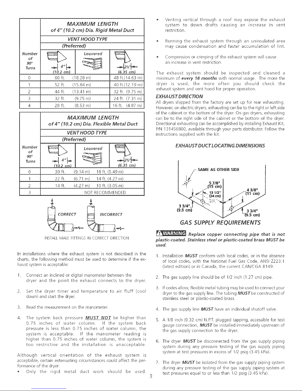
MAXtMUM LENGTH
of 4" (10.2 cm) Dia. Rigid Metal Duct
VENT HOOD TYPE
(Preferred)
Louvered
(10.2 cm)
60 ft. (18.28 m)
52 ft. (15.84 m)
44ft (13.41 m)
32 ft (9,75 m)
28 ft (8,53 m)
(6.35cm)
48 ft,(14,63 m)
40 ft,(12,19 m)
32 ft, (9.75 m)
24 ft, (7.31 m)
16ft (4.87 m)
MAXIMUM LENGTH
of 4" (10.2 cm) Dia. Flexible Metal Duct
VENT HOOD TYPE
(Preferred)
Louvered
(10.2 cm) (6,35 cm)
30 ft (9,14 m) 18 ft (5,49 m)
22 ft (6,71 m) 14 ft (4,27 m)
14 ft (4,27 m) 10 ft (3,05 m)
NOT RECOMMENDED
Venting vertical through a roof may expose the exhaust
system to down drafts causing an increase in vent
restriction,
Running the exhaust system through an uninsulated area
may cause condensation and faster accumulation of lint
Compression or crimping of the exhaust system will cause
an increase in vent restriction
The exhaust system should be inspected and cleaned a
minimum of every 18 months with normal usage The more the
dryer is used, the more often you should check the
exhaust system and vent hood for proper operation
EXHA UST DIRECTION
All dryers shipped from the factory are set up for rear exhausting.
However, on electric dryers, exhausting can be to the right or left side
of the cabinet or the bottom of the dryer, On gas dryers, exhausting
can be to the right side of the cabinet or the bottom of the dryer.
Directional exhausting can be accomplished by installing Exhaust Kit,
P/N 131456800, available through your parts distributor Follow the
instructions supplied with the kit
EXHAUST DUCT LOCATING DIMENSION5
4 3/8"
¢m)
INSTALL MALE FITTINGS IN CORRECT DIRECTION
In installations where the exhaust system is not described in the
charts, the following method must be used to determine if the ex-
haust system is acceptable:
1, Connect an inclined or digital manometer between the
dryer and the point the exhaust connects to the dryer
2, Set the dryer timer and temperature to air fluff (cool
down) and start the dryer
3, Read the measurement on the manometer
The system back pressure MUST NOT be higher than
0,75 inches of water column If the system back
pressure is less than 075 inches of water column, the
system is acceptable, If the manometer reading is
higher than 0,75 inches of water column, the system is
too restrictive and the installation is unacceptable
Although vertical orientation of the exhaust system is
acceptable, certain extenuating circumstances could affect the per-
formance of the dryer:
Only the rigid metal duct work should be used
GAS SUPPLY REQUfREMENTS
Replace copper connecting pipe that is not
plastic-coated. Stainless steel or plastic-coated brass MUST be
used.
1 Installation MUST conform with local codes, or in the absence
of local codes, with the National Fuel Gas Code, ANSI Z2231
(latest edition) or in Canada, the current CAN/CGA B149
2 The gas supply line should be of 1/2 inch (1 27 cm) pipe
3 If codes allow, flexible metal tubing may be used to connect your
dryer to the gas supply line The tubing MUSTbe constructed of
stainless steel or plastic-coated brass
4 The gas supply, line MUST have an individual shutoff valve,
S A 1/8 inch (0.32 cm) N.PT plugged tapping, accessible for test
gauge connection, MUST be installed immediately upstream of
the gas supply, connection to the dryer
6 The dryer MUST be disconnected from the gas supply piping
system during any pressure testing of the gas supply piping
system at test pressures in excess of 1/2 psig (3,45 kPa)
7 The dryer MUST be isolated from the gas supply piping system
during any pressure testing of the gas supply piping system at
test pressures equal to or less than 1/2 psig (3,45 kPa)
LOCATION OF YOUR DRYER
DO NOT INSTALL YOUR DRYER:
1 fnan area exposed to dripping water or outside weather conditions
2 In an area where it will come in contact with curtains, drapes, or
anything that will obstruct the flow of combustion and ventilation
air.
3 On carpet Floor MUST be solid with a maximum slope of 1 inch
(254 cm)
INSTALLATION tN RECESS OR CLOSET
1 A dryer installed in a bedroom, bathroom, recess or closet, MUST
be exhausted outdoors_
2 No other fuel burning appliance shall be installed in the same
closet as the Gas dryer
3 Your dryer needs the space around it for proper ventilation,
DO NOT INSTALL YOUR DRYER IN A CLOSET WITH A SOLID
DOOR.
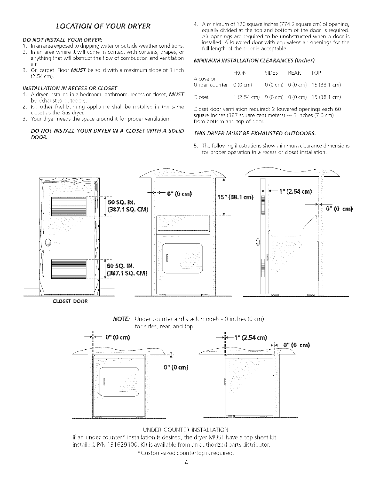
4. A minimum of 120 square inches (7742 square era) of opening,
equally divided at the top and bottom of the door, is required
Air openings are required to be unobstructed when a door is
installed_ A Iouvered door with equivalent air openings for the
full length of the door is acceptable
MINIMUM INSTALLATION CLEARANCES (inches)
FRONT SIDES REAR TOP
Alcove or
Under counter 0(0cm) 0(0cm) 0(0cm) 15(38_1cm)
Closet 1(254cm) 0(0cm) 0(0cm) 15(38_1cm)
Closet door ventilation required; 2 Iouvered openings each 60
square inches (387 square centimeters) -- 3 inches (76 cm)
from bottom and top of door.
THIS DRYER MUST BE EXHAUSTED OUTDOORS,
5, The following illustrations show minimum clearance dimensions
for propel operation in a recess or closet installation
CLOSET DOOR
If an under counter* installation isdesired, the dryer MUST have a top sheet kit
installed, P/N 131629100. Kit isavailable from an authorized parts distributor.
NOTE:
II
--_ii_ 0" (0 era)
i t
Under counter and stack models- 0 inches (0 cm)
for sides, rear, and top.
UNDER COUNTERINSTALLATION
*Custom-sized countertop isrequired.
4

MOBILE HOME INSTALLATION
1. Dryer MUSTbe exhausted outside (outdoors, not beneath
the mobile home) using metal ducting that will not support
combustion. Metal ducting must be 4 inches (I0.16 cm) in
diameter with no obstructions. Rigid metal duct ispreferred.
2. If dryer is exhausted through the floor and area beneath
the mobile home is enclosed, the exhaust system MUST
terminate outside the enclosure with the termination
securelyfastened to the mobile home structure.
3. When installing a gasdryer into a mobile home, a provision
must be made for outside make up air. This provision isto
be not lessthan twice the area of the dryer exhaust outlet.
4. This dryer MUST be fastened to the floor. Mobile Home
Installation Kit No. 169840 isavailable from your dealer.
5. Refer to pages 2 and 3 for other important venting
requirements.
6. Installation MUSTconform to current Manufactured Home
Construction & Safety Standard (which is a Federal
Regulation Title 24 CFR-Part32-80) or when such standard
is not applicable, with American National Standard for
Mobile Horses. In Canada, tile CSA Z240 is applicable.
The dryer isdesigned under ANS! Z 21.5.1 for
HOME USEonly.
UNDER COUNTER & STACK MODELS
ROUGHqN DIMENSIONS
(58.3 cm)
I 26 7/8' t
B'ELECTRtC CONNECTION
UNDER
COUNTER
34 5/8"
(87.9 cm)
13 1/2" -_
(34.4 cm) l
©
Correct
Correct
L
Incorrect
DoN
Incorrect
©
L
T
33/4"
(9.5 cm)
DOOR OPEN 90°
_/8" (&95 cm) DIA.
GAS PIPE
REAR VIEW
47 1/2"
(120.7 cm)
4 3/8"
t" (2.54cm)
L
Correct
Incorrect
L
L
(11.1 cm) _
OPTIONAL
VENT KNOCKOUT_-_
27"
(68.6cm)
SIDE VIEW
3 3/4"
(9.5 cm)

TOP CONSOLE MODELS
ROUGH-IN DiMENSiONS
(68°3 cm}
2 9t16"_
(6.5era}
43 5/8°
(110.7era}
UNPACK/NG
Usingthe four shipping carton cornerposts(two on eachside),
carefully Jay the dryer on its left side and remove foam shipping
base,
To prevent damage, do not use the control panel as a
means to pick up or move the dryer,
NOTE: On under counter model clothes dryers, the top panel
may be removed for installation
2 Return the dryer to an upright position
3_ H
(91.5 cm)
;3 3/4_
(9.5 ¢m}
B
318" {0ogg ¢m} DIA°
GAS PiPE
REAR ViEW
4.3/8"
REVERSING DOOR SWING
Your dryer is designed so the door swing may be reversed at any time
without additional parts, Conversion is accomplished by transferring
hinges to the opposite side of the cabinet
To change the direction of the door opening:
1 Open the dryer door, Remove the four hinge hole plugs from the
left side of the door opening Place nearby for future installation
NOTE: You may need a plastic knife to help pull out the plugs Be
careful not to scratch the paint,
2 Remove the four screws that secure the door hinges to the dryer
front panel (see below), NOTE; Remove one screw from each of
the two hinges first Hold the door firmly before removing the
last two screws,
3 Rotate the door 180 ° and reinstall the door hinges to the dryer
front panel with the four screws
4 Install the four hinge hole plugs in the open screw holes on the
right side of the door opening
(11.1 cm}
OPTIONAL
VENT KNOCKOIJT. _
_" 27'
(68°6 cm}
SIDE ViEW
REMOVE 4 SCREWS
(ONE FROM EACH
HINGE FIRST)
6

ELECTRfCAL INSTALLATION
ALL ELECTRIC Dryers
The following are specific requirements for proper
and safe electrical installation of your dryer Failure to follow
these instructions can create electrical shock and/or a fire hazard.
2. Since your dryer is equipped with a power supply cord having an
equipment-grounding conductor and agrounding plug, the plug
must be plugged into an appropriate outlet that is properly
installed and grounded in accordance with all local codes and
ordinances If in doubt, call a licensed electrician
1 "4LLGASDGvers 1
_liance MUST be_perly grounded Electrical shock can
result if the dryer is not properly grounded Follow the instructions in
this manual for proper grounding_
Do not use an extension cord with this dryer. Some extension
cords are not designed to withstand the amounts of electrical current
this dryer utilizes and can melt, creating electrical shock and/or fire
hazard Locate the dryer within reach of the receptacle for the length
power cord to be purchased, allowing some slack in the cord_ Refer
to the prednstallation requirements in this manual for the proper
power cord to be purchased
A UL approved strain relief must be installed onto power cord_ If
I Non-Canadian ELECTRIC Dryer 1
the strain relief is not attached, the cord can be pulled out of the
dryer and can be cut by any movement of the cord, resulting in
electrical shock
Do not use an aluminum wired receptacle with a cop4serwired
power cord and plug (or vice versa) A chemical reaction occurs
between copper and aluminum and can cause electrical shorts_ The
proper wiring and receptacle is a copper wired power cord with
a copper wired receptacle.
NOTE: Dryers operating on 208 volt power supply will have longer
drying times than operating on 240 volt power supply
GROUNDING REQUIREMENTS
Non-Canadian ELECTR/CDryer
_ Improper connection of the equipment grounding
conductor can result ina riskof electrical shock. Check with a licensed
electrician if you are in doubt as to whether the appliance isproperly
grounded
For a grounded, cord<onnected dryer
1. The dryer MUST be grounded. In the event of a malfunction or
breakdown, grounding will reduce the risk of electrical shock by
a path of least resistance for electrical current.
2, If your dryer is equipped with a power supply cord having an
equipmentogrounding conductor and a grounding plug, the plug
MUST be plugged into an appropriate, copper wired receptacle
that is properly installed and grounded in accordance with all
local codes and ordinances_ If in doubt, call a licensed electrician
Do not modify plug provided with the appliance.
For a permanently connected dryer:
1, The dryer MUST be connected to a grounded metal, permanent
wiring system; or an equipment grounding conductor must be
run with the circuit conductors and connected to the equipment-
grounding terminal or lead on the appliance,
I Canadian ELECTRIC
Improper connection of the equipment grounding
conductor can result ina riskof electrical shock. Check with a licensed 7.
electrician if you are in doubt as to whether the appliance isproperly
grounded 8,
For a grounded, cordoconnected dryer:
1. The dryer must be grounded_ In the event of a malfunction or
breakdown, grounding will reduce the risk of electrical shock by
a path of least resistance for electrical current.
Dryer
1 The laundry center is equipped with a three-prong
(grounding) plug for your protection against shock hazard and
should be plugged directly into a properly grounded
three-prong receptacle Do not cut or remove the
grounding prong from the plug_
ELECTRICAL CONNECTIONS
FOR 3-WIRE SYSTEM
1, Remove the screws securing the terminal block access cover and
the strain relief mounting bracket located on the back of the
dryer upper corner_
Install a U.L approved strain relief into the power cord entry hole
of the mounting bracket Finger tighten the nut only at this time
GREEN GROUND SCREW
NEUTRAL
WIRE
BRACKET POWER CORD
3,
Thread a UL approved 30 amp, power cord, NEMA 10-30 Type
SRDT, through the strain relief.
4,
Attach the power cord neutral (center wire) conductor to the
silver colored center terminal on the terminal block, Tighten the
screw securely
5. Attach the remaining two power cord outer conductors to the
outer brass colored terminals on the terminal block Tighten both
screws securely
at connections_
6,
Reattach the strain relief mounting bracket to the back of the
Do not make a sharp bend or crimp wiring/conductor
dryer with two screws. Tighten screws securely
Tighten the screws securing the cord restraint firmly against the
power cord_
Tighten the strain relief nut securely so that the strain relief does
not turn
9. Reinstall the terminal block cover
,SILVER TERMINAL
UT
TIGHTEN NUT TO
THESE THREADS
 Loading...