


247889780

Operator’s Manual
SNOW THROWER
Model Nos. 247.88976*
247.88 97 8*
247.88870*
247.88874*
* -- Last digit of model number varies
SNOW THROWER
Model Nos. 247.88172*
247.88173*
247.88 39 4*
247.88396*
247.88 433*
247.88640*
247.88694*
247.88 781*
247.88 78 9*
* -- Last digit of model number varies
CAUTION: Before using this product,
read this manual and follow all safety
rules and operating instructions.
• SAFETY
• UNPACKING
• ASSEMBLY
• OPERATION
• MAINTENANCE
• ESPAÑOL
Sears Brands Management Corporation, Hoffman Estates, IL 60179, U.S.A.
Visit our website: www.craftsman.com
Form No. 769-12240
(June 23, 2017)

TABLE OF CONTENTS
Safe Operation Practices .........................Page 3
Assembly ........................................Page 7
Operation ......................................Page 21
Service &Maintenance .......................... Page 28
Engine Oil: 5W-30
Fuel: Unleaded Gasoline
Spark Plug: F6RTC (Sears Part #951-10292)
Spark Plug Gap: .020” to 0.030”
Off-Season Storage ............................. Page 36
Troubleshooting ............................... Page 37
Warranty Statement ...........See Separate Supplement
Español ........................................ Page 39
MODEL NUMBERPRODUCT SPECIFICATIONS
Model Number ________________________________
Serial Number _________________________________
Date of Purchase _______________________________
Record the model number, serial number,
and date of purchase above.
© Sears Brands, LLC
2

SAFETY INSTRUCTIONS
WARNING
This symbol points out important safety instructions which, if not
followed, could endanger the personal safety and/or property of
yourself and others. Read and follow all instructions in this manual
before attempting to operate this machine. Failure to comply with these
instructions may result in personal injury. When you see this symbol, HEED
ITS WARNING!
WARNING
CALIFORNIA PROPOSITION 65
Engine Exhaust, some of its constituents, and certain vehicle components
contain or emit chemicals known to State of California to cause cancer and
birth defects or other reproductive harm.
TRAINING
• Read, understand, and follow all instructions on the machine and in the
manual(s) before attempting to assemble and operate. Failure to do so can
result in serious injur y to the operator and/or bystanders. Keep this manual
in a safe place for future and regular reference and for ordering replacement
parts.
• Be familiar with all controls and their proper operation. Know how to stop
the machine and disengage them quickly.
• Never allow children under 14 years of age to operate this machine. Children
14 and over should read and understand the instructions and safe operation
practices in this manual and on the machine and be trained and supervised
by an adult.
• Never allow adults to operate this machine without proper instruction.
• Thrown objects can cause serious personal injury. Plan your snow-throwing
pattern to avoid discharge of material toward roads, bystanders and the like.
• Keep bystanders, pets and children at least 75 feet from the machine while it
is in operation. Stop machine if anyone enters the area.
• Exercise caution to avoid slipping or falling, especially when operating in
reverse.
PREPARATION
• Thoroughly inspect the area where the equipment is to be used. Remove all
doormats, newspapers, sleds, boards, wires and other foreign objects, which
could be tripped over or thrown by the auger/impeller.
• Always wear safety glasses or eye shields during operation and while
performing an adjustment or repair to protect your eyes. Thrown objects
which ricochet can cause serious injury to the eyes.
• Do not operate without wearing adequate winter outer garments. Do not
wear jewelry, long scarves or other loose clothing, which could become
entangled in moving parts. Wear footwear which will improve footing on
slippery surfaces.
• Use a grounded three-wire extension cord and receptacle for all machines
with electric start engines.
DANGER
This machine was built to be operated according to the safe operation
practices in this manual. As with any type of power equipment,
carelessness or error on the part of the operator can result in serious injury.
This machine is capable of amputating fingers, hands, toes and feet and
throwing debris. Failure to observe the following safety instructions could
result in serious injury or death.
WARNING
Your Responsibility—Restrict the use of this power machine to
persons who read, understand and follow the warnings and instructions in
this manual and on the machine.
SAVE THESE INSTRUCTIONS!
• Disengage all control levers before starting the engine.
• Adjust collector housing height to clear gravel or crushed rock surfaces.
• Never attempt to make any adjustments while engine is running, except
where specifically recommended in the operator’s manual.
• Let engine and machine adjust to outdoor temperature before starting to
clear snow.
Safe Handling of Gasoline:
To avoid personal injury or property damage use extreme care in handling
gasoline. Gasoline is extremely flammable and the vapors are explosive.
Serious personal injury can occur when gasoline is spilled on yourself or your
clothes which can ignite. Wash your skin and change clothes immediately.
• Use only an approved gasoline container.
• Never fill containers inside a vehicle or on a truck or trailer bed with a plastic
liner. Always place containers on the ground away from your vehicle before
filling.
• When practical, remove gas-powered equipment from the truck or
trailer and refuel it on the ground. If this is not possible, then refuel such
equipment on a trailer with a portable container, rather than from a gasoline
dispenser nozzle.
• Keep the nozzle in contact with the rim of the fuel tank or container opening
at all times until fueling is complete. Do not use a nozzle lock-open device.
• Extinguish all cigarettes, cigars, pipes and other sources of ignition.
• Never fuel machine indoors.
• Never remove gas cap or add fuel while the engine is hot or running. Allow
engine to cool at least two minutes before refueling.
• Never over fill fuel tank. Fill tank to no more than ½ inch below bottom of
filler neck to allow space for fuel expansion.
• Replace gasoline cap and tighten securely.
• If gasoline is spilled, wipe it off the engine and equipment. Move unit to
another area. Wait 5 minutes before starting the engine. If fuel is spilled on
clothing, change clothing immediately.
3

SAFETY INSTRUCTIONS
• To reduce fire hazards, keep machine free of grass, leaves, or other debris
build-up. Clean up oil or fuel spillage and remove any fuel soaked debris.
• Never store the machine or fuel container inside where there is an open
flame, spark or pilot light as on a water heater, space heater, furnace, clothes
dryer or other gas appliances.
OPERATION
• Do not put hands or feet near rotating parts, in the auger/impeller housing
or chute assembly. Contact with the rotating parts can amputate hands and
feet.
• The auger/impeller control lever is a safety device. Never bypass its
operation. Doing so makes the machine unsafe and may cause personal
inj ury.
• The control levers must operate easily in both directions and automatically
return to the disengaged position when released.
• Never operate with a missing or damaged chute assembly. Keep all safety
devices in place and working.
• Never run an engine indoors or in a poorly ventilated area. Engine exhaust
contains carbon monoxide, an odorless and deadly gas.
• Do not operate machine while under the influence of alcohol or drugs.
• Muffler and engine become hot and can cause a burn. Do not touch. Keep
children away.
• Exercise extreme caution when operating on or crossing gravel surfaces. Stay
alert for hidden hazards or traffic.
• Exercise caution when changing direction and while operating on slopes. Do
not operate on steep slopes.
• Plan your snow-throwing pattern to avoid discharge towards windows,
walls, cars etc. Thus, avoiding possible property damage or personal injury
caused by a ricochet.
• Never direct discharge at children, bystanders and pets or allow anyone in
front of the machine.
• Do not overload machine capacity by attempting to clear snow at too fast of
a rate.
• Never operate this machine without good visibility or light. Always be sure of
your footing and keep a firm hold on the handles. Walk, never run.
• Disengage power to the auger/impeller when transporting or not in use.
• Never operate machine at high transport speeds on slippery surfaces. Look
down and behind and use care when backing up.
• After striking a foreign object or if the machine should start to vibrate
abnormally, stop the engine, disconnect the spark plug wire and ground
it against the engine. Inspect thoroughly for damage. Repair any damage
before starting and operating.
• Disengage all control levers and stop engine before you leave the operating
position (behind the handles). Wait until the auger/impeller comes to
a complete stop before unclogging the chute assembly, making any
adjustments, or inspections.
• Never put your hand in the discharge or collector openings. Do not unclog
chute assembly while engine is running. Shut off engine and remain behind
handles until all moving parts have stopped before unclogging.
• Use only attachments and accessories approved by the manufacturer (e.g.
wheel weights, tire chains, cabs etc.).
• When starting engine, pull cord slowly until resistance is felt, then pull
rapidly. Rapid retraction of starter cord (kickback) will pull hand and arm
toward engine faster than you can let go. Broken bones, fractures, bruises or
sprains could result.
• If situations occur which are not covered in this manual, use care and good
judgment.
CLEARING A CLOGGED DISCHARGE CHUTE
Hand contact with the rotating impeller inside the discharge chute is the most
common cause of injury associated with snow throwers. Never use your hand to
clean out the discharge chute.
To clear the chute:
a. SHUT THE ENGINE OFF!
b. Wait 10 seconds to be sure the impeller blades have stopped
rotating.
c. Always use a clean-out tool, not your hands.
MAINTENANCE & STORAGE
• Never tamper with safety devices. Check their proper operation regularly.
Refer to the maintenance and adjustment sections of this manual.
• Before cleaning, repairing, or inspecting machine disengage all control
levers and stop the engine. Wait until the auger/impeller come to a complete
stop. Disconnect the spark plug wire and ground against the engine to
prevent unintended starting.
• Check bolts and screws for proper tightness at frequent intervals to keep the
machine in safe working condition. Also, visually inspect machine for any
damage.
• Do not change the engine governor setting or over-speed the engine. The
governor controls the maximum safe operating speed of the engine.
• Snow thrower shave plates and skid shoes are subject to wear and damage.
For your safety protection, frequently check all components and replace
with original equipment manufacturer’s (OEM) parts only as listed in the
Parts pages of this operator’s manual. Use of parts which do not meet the
original equipment specifications may lead to improper performance and
compromise safety!
• Check control levers periodically to verify they engage and disengage
properly and adjust, if necessary. Refer to the adjustment section in this
operator’s manual for instructions.
• Maintain or replace safety and instruction labels, as necessary.
4

SAFETY INSTRUCTIONS
• Observe proper disposal laws and regulations for gas, oil, etc. to protect the
environment.
• Prior to storing, run machine a few minutes to clear snow from machine and
prevent freeze up of auger/impeller.
• Never store the machine or fuel container inside where there is an open
flame, spark or pilot light such as a water heater, furnace, clothes dryer etc.
• Always refer to the operator’s manual for proper instructions on off-season
storage.
• Check fuel line, tank, cap, and fittings frequently for cracks or leaks. Replace
if necessary.
• Do not crank engine with spark plug removed.
• According to the Consumer Products Safety Commission (CPSC) and the
U.S. Environmental Protection Agency (EPA), this product has an Average
Useful Life of seven (7) years, or 60 hours of operation. At the end of
the Average Useful Life have the machine inspected annually by an
authorized service dealer to ensure that all mechanical and safety systems
are working properly and not worn excessively. Failure to do so can result in
accidents, injuries or death.
DO NOT MODIFY ENGINE
To avoid serious injury or death, do not modify engine in any way. Tampering
with the governor setting can lead to a runaway engine and cause it to
operate at unsafe speeds. Never tamper with factory setting of engine
governor.
NOTICE REGARDING EMISSIONS
Engines which are certified to comply with California and federal EPA
emission regulations for SORE (Small Off Road Equipment) are certified
to operate on regular unleaded gasoline, and may include the following
emission control systems: Engine Modification (EM), Oxidizing Catalyst (OC),
Secondary Air Injection (SAI) and Three Way Catalyst (TWC) if so equipped.
5

SAFETY INSTRUCTIONS
SAFETY SYMBOLS
This page depicts and describes safety symbols that may appear on this product. Read, understand, and follow all instructions on the machine before
attempting to assemble and operate.
Symbol Description
READ THE OPERATOR’S MANUAL(S)
Read, understand, and follow all instructions in the manual(s) before attempting to assemble and
operate.
WARNING— ROTATING BLADES
Keep hands out of inlet and discharge openings while machine is running. There are rotating blades
inside.
WARNING— ROTATING BLADES
Keep hands out of inlet and discharge openings while machine is running. There are rotating blades
inside.
WARNING— ROTATING AUGER
Do not put hands or feet near rotating parts, in the auger/impeller housing or chute assembly.
Contact with the rotating parts can amputate hands and feet.
WARNING—THROWN OBJECTS
This machine may pick up and throw and objects which can cause serious personal injury.
WARNING—GASOLINE IS FLAMMABLE
Allow the engine to cool at least two minutes before refueling.
WARNING— CARBON MONOXIDE
Never run an engine indoors or in a poorly ventilated area. Engine exhaust contains carbon
monoxide, an odorless and deadly gas.
WARNING— ELECTRICAL SHOCK
Do not use the engine’s electric starter in the rain.
WARNING— HOT SURFACE
Engine parts, especially the muffler, become extremely hot during operation. Allow engine and
muffler to cool before touching.
WARNING: Your Responsibility—Restrict the use of this power machine to persons who read, understand and follow
the warnings and instructions in this manual and on the machine.
SAVE THESE INSTRUCTIONS!
6
ASSEMBLY
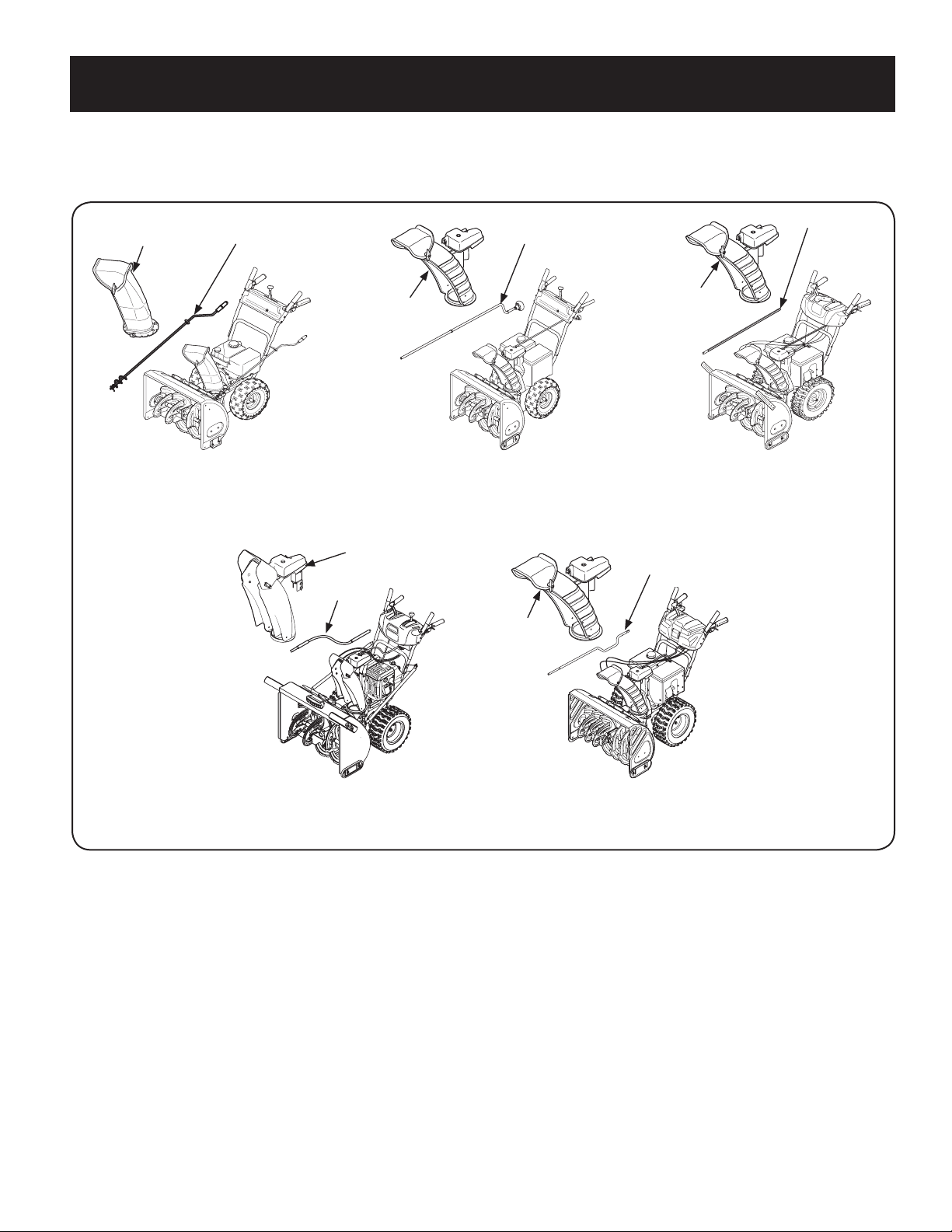
Electric Chute Control
Pag e 16
Manual Chute
Control Rod
Chute
Assembly
Flex Shaft
Overhead Chute Control
(w/ Flex Shaft Steel Chute)
Pag e 14
Chute Assembly
Standard Side Crank Chute Control
Page 10
Standard Side Crank Rod
Assembly
Chute
Assembly
Overhead Chute Control
(w/ Chute Control Rod)
Pa ge 11
Overhead Chute
Control Rod
Chute
Assembly
2-Way & 4-Way Chute Control
Page 12
Chute Control Rod
Chute
Assembly
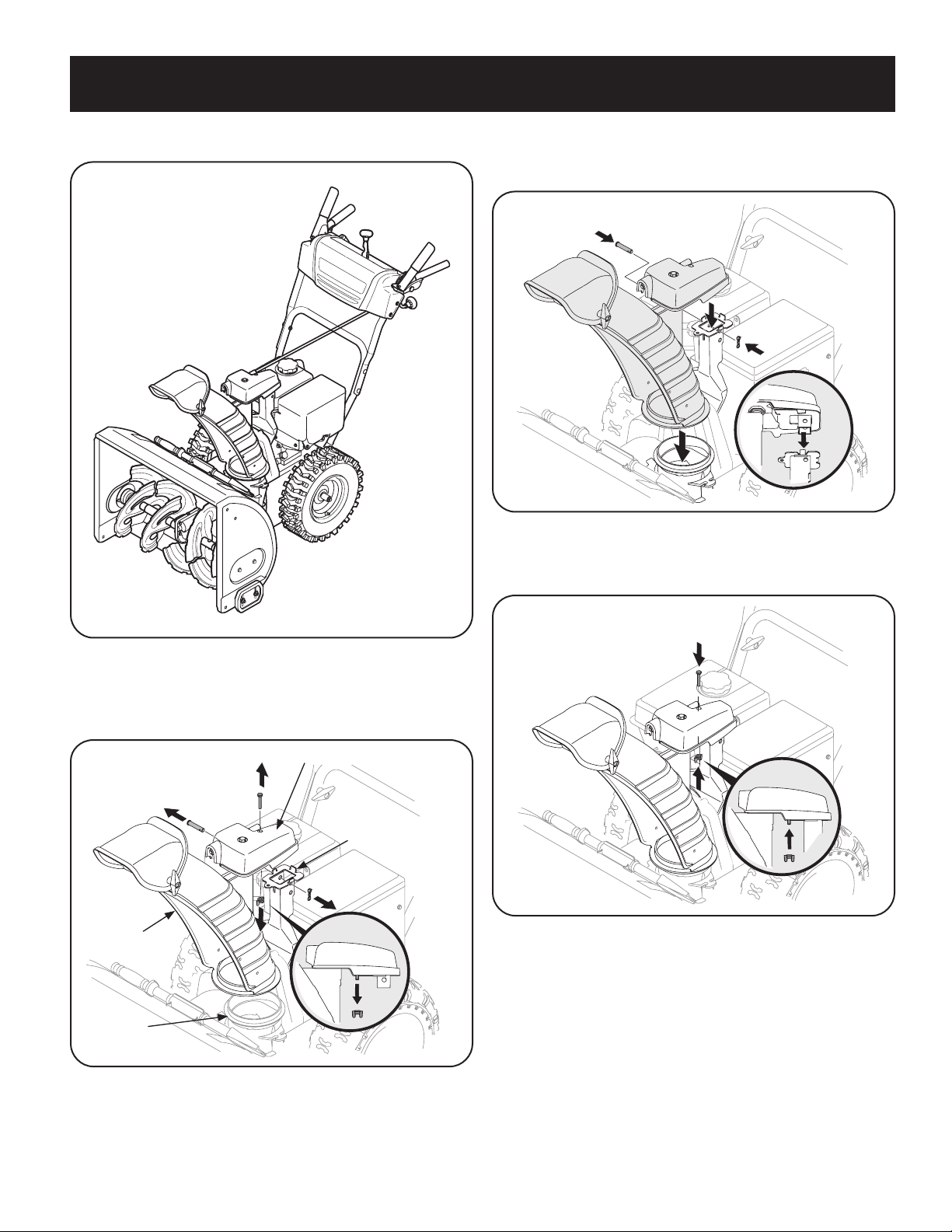
NOTE: This Operator’s Manual covers several models. Features may vary by model. Not all features in this manual are applicable to all models and the model depicted may
differ from yours. Refer to Figure 1 which shows the different versions and match the contents of carton (chute and directional control rod/flex shaft) to identify your
specific unit.
Figure 1
7
ASSEMBLY
NOTE: References to right or left side of the snow thrower are determined from
behind the unit in the operating position (standing directly behind the snow
thrower, facing the handle panel).
UNPACKING: Removing From Carton
1. Cut the corners of the carton and lay the sides flat on the ground. Remove
and discard all packing inserts.
2. Move the snow thrower out of the carton.
3. Make certain the carton has been completely emptied before discarding it.
Handle Assembly
Refer to Figure 1 and proceed to your applicable chute style.
1. Cut cable ties securing chute control rod or upper handle to the lower handle
(if applicable), set aside the chute control rod (if applicable) and remove the
wrap around the handles (if applicable).
NOTE: Do not cut the cable tie securing the cables to the engine for units equipped.
NOTE: On units with Overhead Chute Control, Four-Way Chute Control, and Electric
Chute Control cut cable ties securing flex shaft to the lower handle and set the flex
shaft aside. Remove rubber bands securing cables to carriage screws and cut cable
tie securing shif t rod to lower handle. Refer to Figure to help identify your unit.
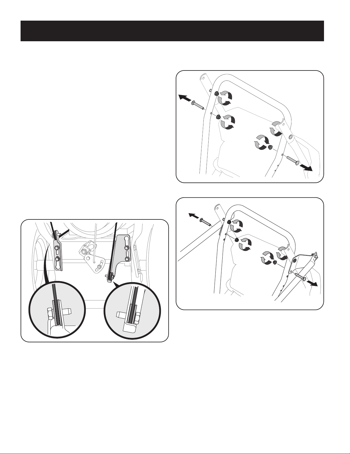
2. Observe the lower rear area of the snow thrower to be sure both cables are
aligned with roller guides before pivoting the handle upward. See Figure 2.
3. Loosen the top two lock nuts securing the upper and lower handle and
remove the two carriage screws from the lower handle and set aside. See
Figure 3 or Figure 4 for units with side supports.
Figure 3
Figure 2
Figure 4
8
ASSEMBLY
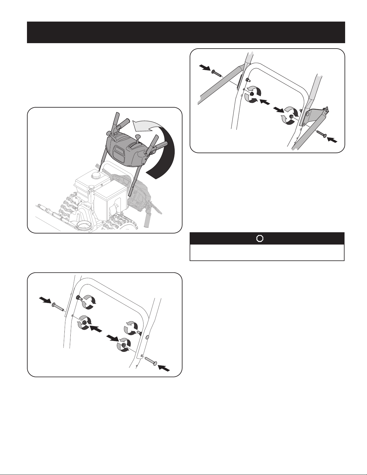
4. Place shift lever in Forward-6 position or fastest forward speed (if equipped).
5. Pull up and back on upper handle as shown in Figure 5. As you are raising the
handle upward, make sure that both ends of the center cable are positioned
properly in the brackets. Align upper handle with the lower handle.
NOTE: On select units with steel rod speed selectors, you may need to lower shift
rod to the side slightly to maneuver handle panel over it when pivoting handle
upward.
Figure 7
7. Remove and discard any rubber bands, if present. They are for packaging
purposes only.
8. On units equipped with cable guides on top of the engine, check that all
cables are properly routed through the cable guide. Then pull the cables
towards the chute and pull the cable tie on the engine snug on the cables to
secure in place.
NOTE: For smoothest operation, cables should all be to the left of the chute
directional control rod.
Figure 5
6. Attach the two carriage screws and lock nuts removed in Step 2. Finish
securing the handle by tightening the top two lock nuts loosened in Step 2.
See Figure 6 or Figure 7 for units with side supports.
Figure 6
STOP
Refer to Figure 1 to identify your applicable chute style and continue to
Chute Assembly Options (page 9).
Chute Assembly Options
Refer to Figure 1 and proceed to your applicable Chute Control Style on pages 10-17.
9
ASSEMBLY
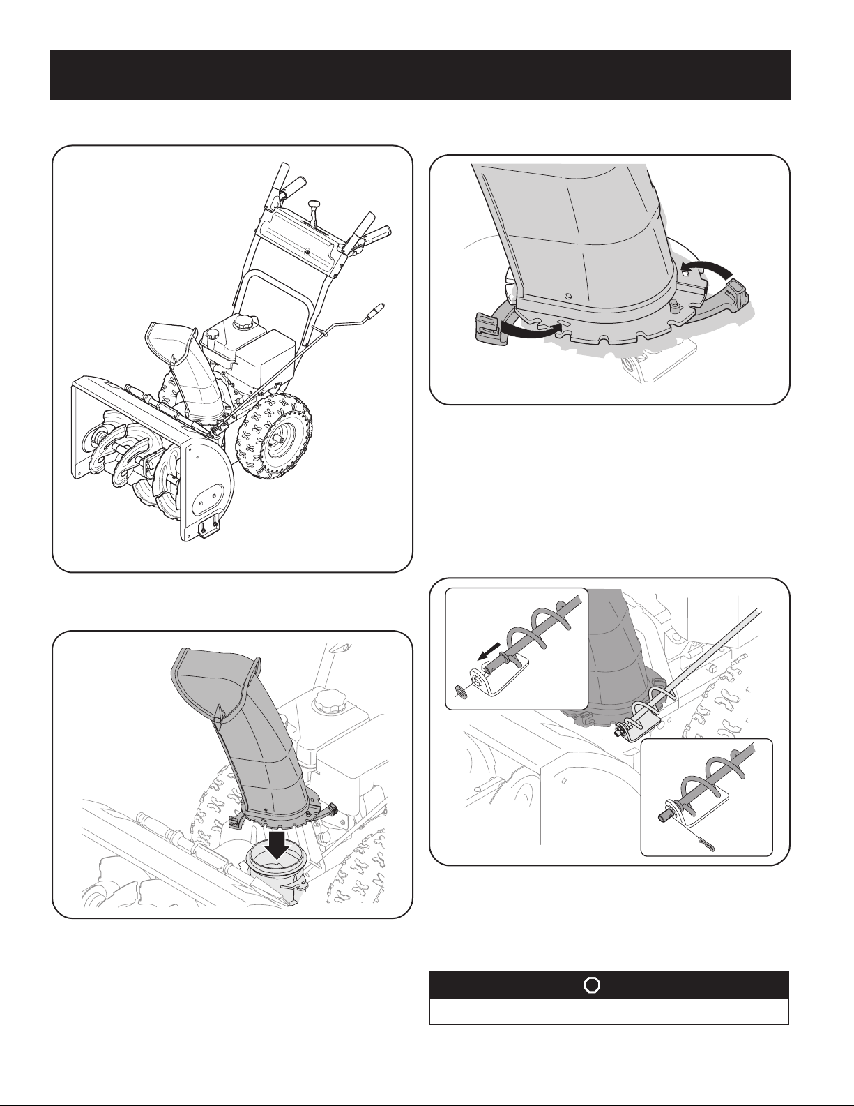
Standard Side Crank Chute Control
2. Close flange keepers to secure chute assembly to chute base. Flange keepers
will click into place when properly secure. See “Figure 10”10.
Figure 10
NOTE: Ensure the lower chute is secured to the flange on the chute base. The lower
edge of the chute keeper should be positioned below the flange on the chute base
after being clicked into place. If flange keepers will not easily click into place, use
palm of your hand to apply swif t, firm pressure to the back of each.
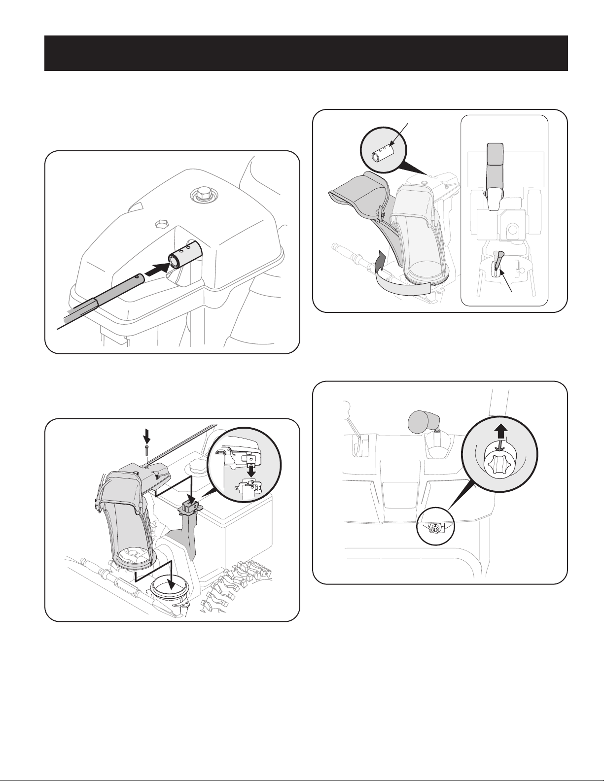
Chute Directional Control Assembly
1. Remove plastic cap (if present), flat washer and hairpin clip from end of
chute directional control assembly. See Figure 11.
Figure 8
1. Position chute assembly over base. See Figure 9.
Figure 9
Fi gur e 11
2. Insert end of chute directional control assembly into lower bracket and
secure chute directional control assembly with flat washer and hairpin clip
removed in Step 1. If necessary, lower bracket can be adjusted. Refer to
Chute Bracket Adjustment in Service section on page 32.
STOP
Continue to Set-Up (page 18).
10
ASSEMBLY
Chute Support Bracket
Chute Control Head
Chute
Chute Base
Overhead Chute Control (w/ Chute Control Rod)
2. Place chute assembly onto chute base and secure chute control head to chute
support bracket with clevis pin and cotter pin removed in Step 1. See Figure
14.
Fig ure 14
3. Finish securing chute control head to chute support bracket with wing
nut (a) and hex screw (b) removed in Step 1. See Figure 15.
Figur e 12
1. Remove wing nut and hex screw from chute control head and clevis pin and
cotter pin from chute support bracket. Position chute assembly (forwardfacing) over chute base. See Figure 13.
Figur e 13
Figur e 15
11

ASSEMBLY
Chute Control Head
Chute
Chute Support
Bracket
Chute Base
4. Insert chute control rod into the support bracket on rear of the dash panel.
See Figure 16.
Fig ure 16
5. Remove hairpin clip (a) from rear of chute control head. See Figure 17.
2-Way & 4-Way Chute Control
Fi gure 17
6. Insert chute control rod (b) into rear of chute control head. See Figure 17.
Secure chute control rod to chute control assembly with hairpin clip removed
in Step 5.
Continue to Set-Up (page 18).
STOP
Fig ure 18
1. Remove hairpin clip, wing nut and hex screw from chute control head and
clevis pin and bow-tie cotter pin from chute support bracket. See Figure 19
Fig ure 19
12
ASSEMBLY
Chute Control Input
Top Vie w
Joystick
NOTE: For smoothest operation, cables should all be to the left of the chute
directional control rod.
2. Insert chute control rod into chute control head. Push rod as far into chute
control head as possible, keeping holes in rod pointing upward. See
Figure 20.
Figure 20
3. Place chute onto chute base and ensure chute control rod is positioned under
handle panel. Install hex screw removed in Step 1, but do not secure with
wing nut at this time. Figure 21.
4. Squeeze trigger on joystick and rotate chute by hand to face forward. The
holes in chute control input will be facing up. See Figure 22.
Figure 22
NOTE: Chute will not rotate without squeezing trigger on joystick.
5. Rotate joystick to one o’clock position so that indicator arrow on pinion gear
below control panel faces upward. See Figure 23.
Figure 21
Figure 23
6. Insert chute control rod into pinion gear below joystick. Make sure to line up
hole in rod with arrow on pinion gear. See Figure 24.
13
ASSEMBLY
Chute
Assembly
Chute Base
Chute
Suppor t
Bracket
Chute Control
Head
Figu re 24
NOTE: Chute control rod will fit snug into pinion gear. Support rear of dash
panel with one hand while inserting rod with your other hand to ensure rod
is inserted all the way into pinion gear.
NOTE: The hole in the chute directional control rod is a reference for aligning
rod with indicator arrow on pinion gear, and will be visible after rod has been
inserted.
7. Push chute control rod toward control panel until hole in rod lines up with
hole in chute control input closest to chute control head and insert hairpin
clip (a)removed in Step 1. See Figure 25.
Overhead Chute Control (w/ Flex Shaft & Steel Chute)
Figur e 26
1. Remove lock nuts and hex screws from chute support bracket (this will
require two wrenches). See Figure 27.
2. Place chute assembly onto chute base and chute control head onto chute
support bracket. See Figure 27.
Figure 25
NOTE: Second hole is used to achieve further engagement of chute control
rod into pinion gear if required. Refer to Service section for Chute Control
Rod adjustments.
8. Finish securing chute control head to chute support bracket with wing nut,
clevis pin, and bow-tie cotter pin (e) removed in Step 1.
STOP
Continue to Set-Up (page 18).
Figur e 27
14
ASSEMBLY
3. Secure chute control head to chute support bracket with lock nuts and hex
screws removed in Step 1. See Figure 28.
Figure 28
NOTE: For smoothest operation, the cables should all be to the left of the chute
control rod.
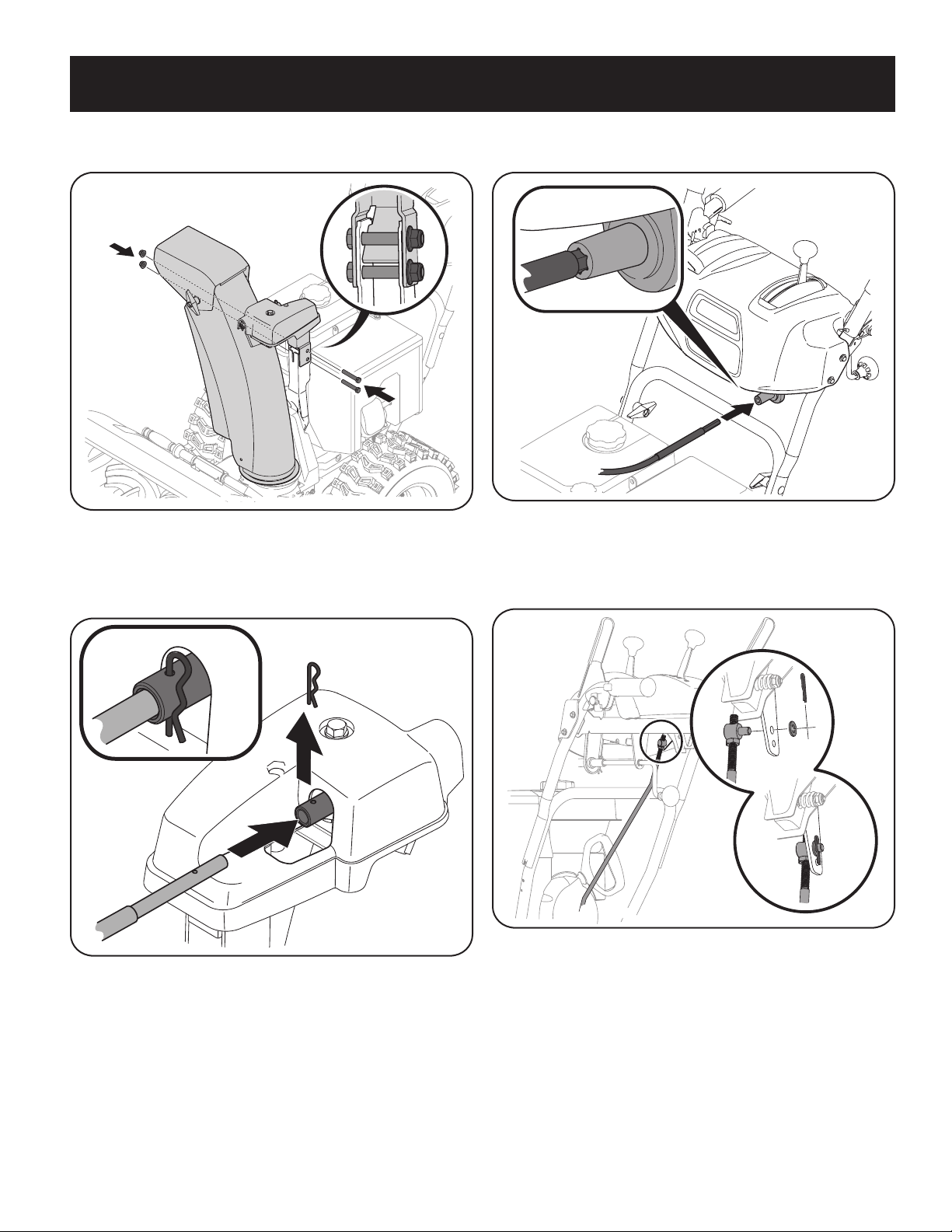
4. Remove hairpin clip from rear of chute control assembly. See Figure 29.
6. Insert hex end of flex shaf t into chute control rod coupling under dash panel.
See Figure 30.
Figure 30
7. Ensure speed selector is in fastest forward speed.
8. Remove cotter pin and washer from ferrule on end of shift rod. See Figure 31
inset.
Figure 29
5. Insert flex shaft removed during handle assembly from lower handle into
rear of chute directional control head. See Figure 29. Secure f lex shaft to
chute control head with hairpin clip removed in Step 4.
Fig ure 31
15

ASSEMBLY
Chute Control Head
Chute
1
1
2
Chute
Support
Bracket
Chute Base
9. Make sure the shift lever on the back of the transmission is rotated
downward to the full extent of its rotation. See Figure 32.
Figu re 32
10. Insert ferrule into top hole of shif t lever and secure with cotter pin (a) and
washer (b) removed in Step 8. See Figure 31. Ferrule may need to be adjusted
up or down.
Electric Chute Control
Continue to Set-Up (page 18).
STOP
Figu re 33
1. Remove cotter pin, wing nut, and hex screw from chute control head and
clevis pin and bow-tie cotter pin from chute support bracket. See Figure 34.
Figure 34
NOTE: For smoothest operation, the cables should all be to the left of the chute
control rod.
16
ASSEMBLY
2. Insert the round end of the chute control rod into input of chute control
head. Push rod as far into the chute control head as possible, keeping the
holes in the rod pointing upward. See Figure 35.
Figu re 35
3. Place chute onto chute base and ensure chute control rod is positioned under
handle panel. Secure chute control head to chute support bracket with clevis
pin and bow-tie cotter pin removed in Step 1. See Figure 36.
4. Finish securing chute control head by installing hex screw and wing nut
removed in Step 2. See Figure 37.
Figure 37
5. Insert the other end of the chute control rod into the input shaf t below the
handle panel. Make sure to line up the flat end of the rod and the flat end
of the input shaft. You may need to rotate the rod around until these two
surfaces line up. See Figure 38.
Figure 36
Figure 38
17

ASSEMBLY
6. Push the chute control rod toward the control panel until the hole in the rod
lines up with the middle hole in the chute control input and insert the cotter
pin removed in Step 1. See Figure 39.
Figure 39
NOTE: There is a reference hole provided at rear end of control rod to help
know when holes are vertical.
NOTE: The hole fur thest from the chute control head is used to achieve
further engagement of the chute control rod into the input shaft if required.
Refer to Page 33 of the Maintenance & Adjustments section for Chute Control
Rod adjustment.
The hole closest to the chute control head is used for manual movement of
the chute assembly if required. Refer to page 24 of the Operation section.
Set-Up
Chute Control Cable Routing (If Equipped)
For units equipped with 2-way or 4-way chute control joystick, electric
chute control and/or chute-pitch controls, ensure control cables are routed
properly.
NOTE: For smoothest operation, cables should all be to the left of the chute
directional control rod.
NOTE: The number of cables routed through the wire guides will depend on
unit model.
1. Locate cable guide on top of engine and ensure cable(s) are properly routed
through the cable guide. See Figure 40.
Figure 40
Continue to Set-Up (page 18).
STOP
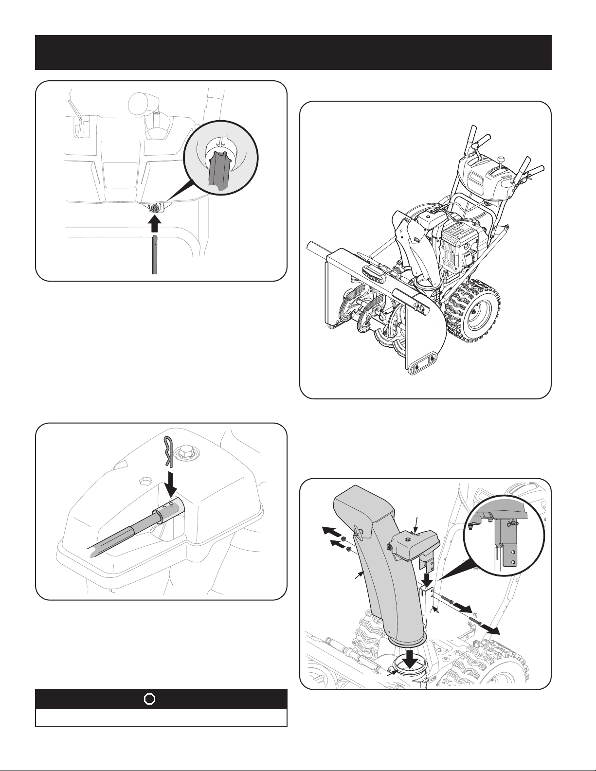
Shear Pins
Holes are located in the plastic dash panel for convenient shear pin storage. See
Figure 41. Refer to page 16 28 in the Operation section for more information
regarding shear pin replacement.
NOTE: If the extra shear pins are not already assembled in the handle panel, they
can be found in the manual bag.
18
Fig ure 41
ASSEMBLY
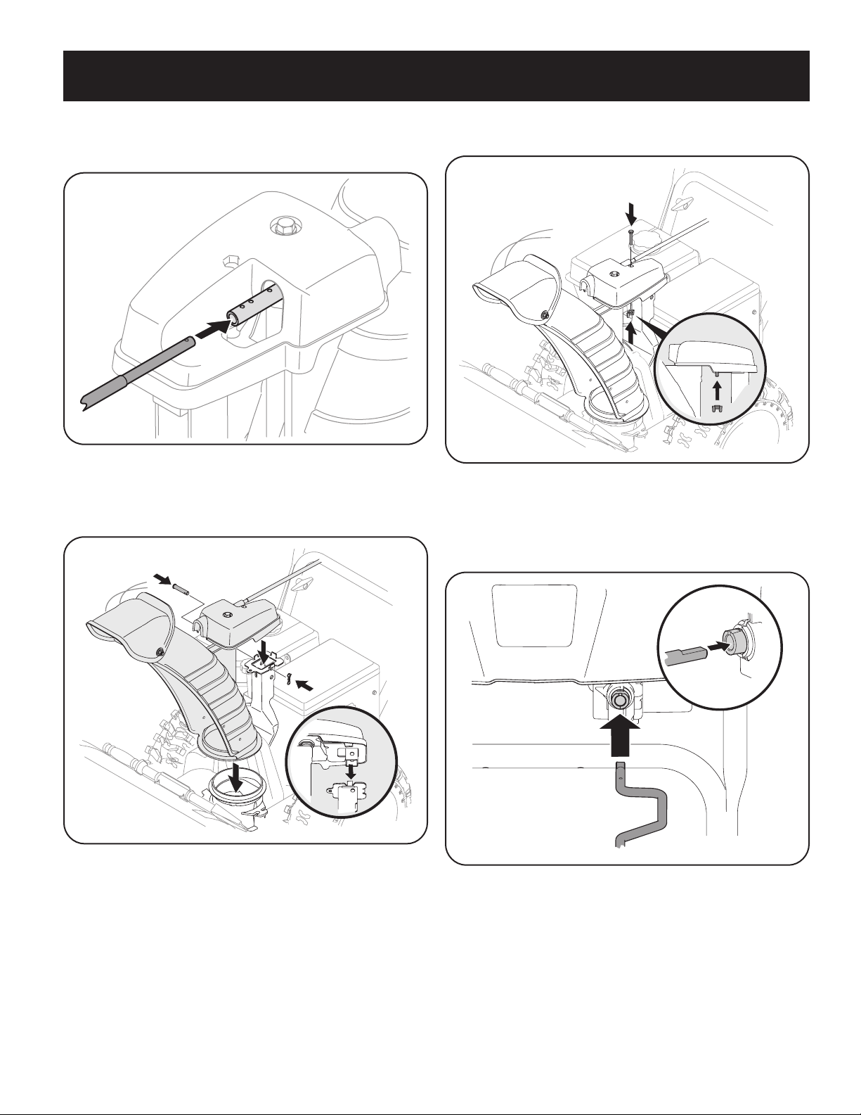
Chute Clean-Out Tool
Chute Clean-Out Tool
A chute clean-out tool is fastened to the top of the auger housing with a mounting
clip. See Figure 42. The tool is designed to clear a chute assembly of ice and
snow. This item is fastened with a cable tie at the factory. Cut the cable tie before
operating the snow thrower.
WARNING
Never use your hands to clear a clogged chute assembly. Shut OFF engine
and remain behind handles until all moving parts have stopped before
using the clean-out tool to clear the chute assembly.
Figur e 42
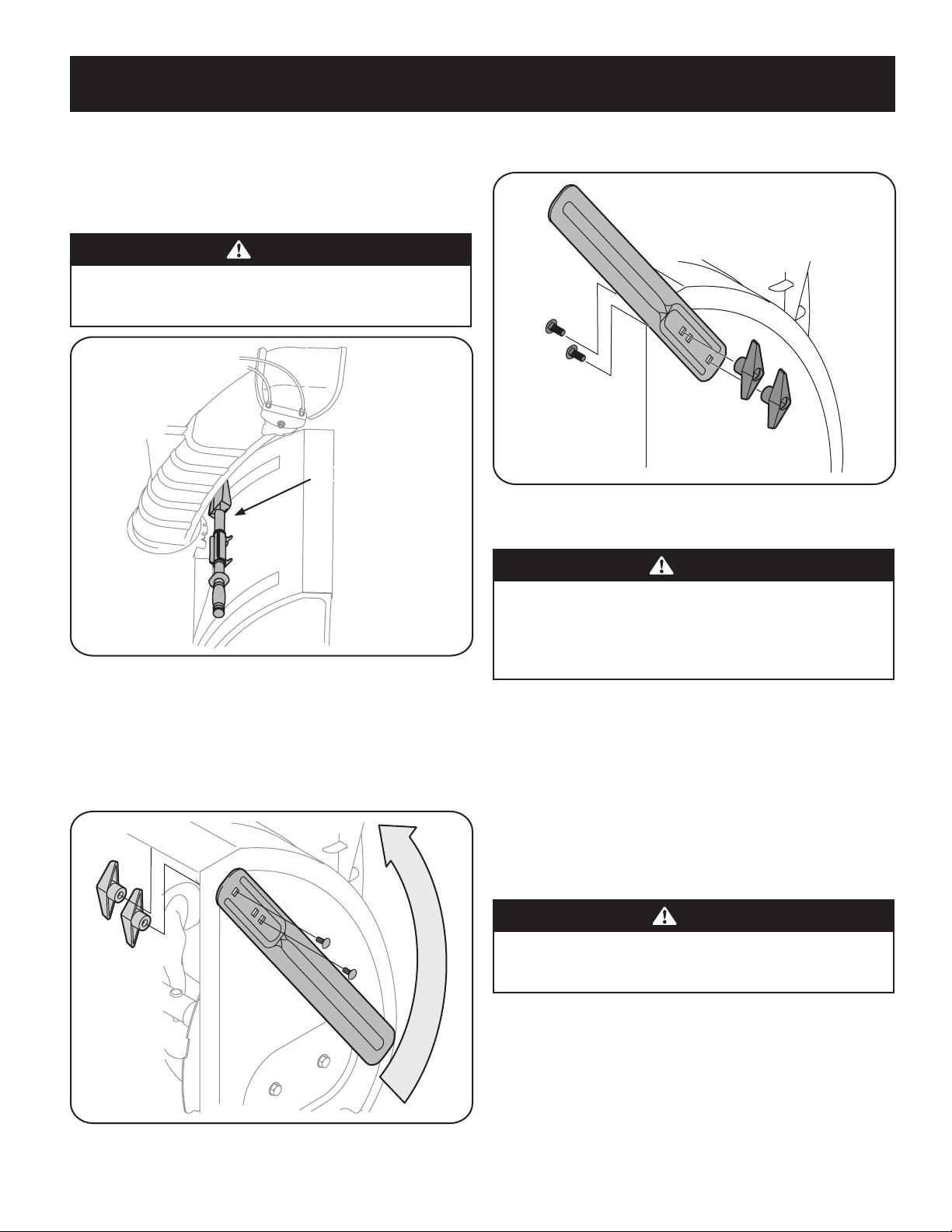
Drift Cutters (if equipped)
1. Remove the two screws and wing knobs that secure each drift cutter, and
remove them from the sides of the auger housing.
2. Turn the drift cutters around and position them as shown in Figure 43 to the
outside of the auger housing.
3. Attach the drift cutters with the screws and wing knobs on the outside of the
auger housing as shown in Figure 44.
Figure 44
Tire Pressure (If Applicable)
WARNING
Under any circumstance do not exceed manufacturer’s recommended psi.
Equal tire pressure should be maintained at all times. Excessive pressure
when seating beads may cause tire/rim assembly to burst with force
sufficient to cause serious injury. Refer to sidewall of tire for recommended
pressure.
The tires are over-inflated for shipping purposes. Check the tire pressure before
operating the snow thrower. Refer to the tire side wall for tire manufacturer’s
recommended psi and deflate (or inflate) the tires as necessar y.
NOTE: Equal tire pressure is to be maintained at all times for per formance purposes.
Adjustments
Figur e 43
Skid Shoes
The snow thrower skid shoes are adjusted at the factory to be approx 1/8” below
the bottom surface of the shave plate. Adjust them downward, if desired, prior to
operating the snow thrower.
CAUTION
It is not recommended that you operate this snow thrower on gravel as
it can easily pick up and throw loose gravel, causing personal injury or
damage to the snow thrower and surrounding property.
• For close snow removal on a smooth surface, raise skid shoes higher on the
auger housing. Refer to Figure 45.
• Use a middle or lower position when the area to be cleared is uneven, such as
a gravel driveway.
NOTE: If you choose to operate the snow thrower on a gravel surface, keep
the skid shoes in position for maximum clearance between the ground and
the shave plate.
19
ASSEMBLY
Smooth Surface
Uneven Surface
Auger Control
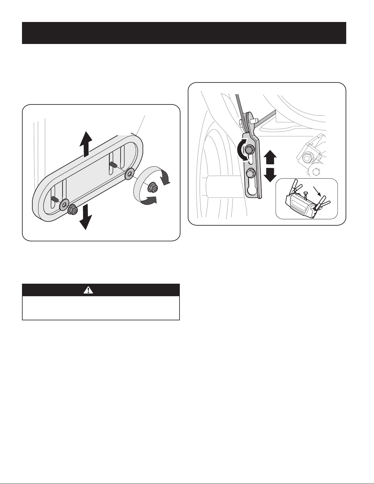
To adjust the skid shoes:
1. Loosen the four hex nuts (two on each side), flat washers, and carriage bolts.
Move skid shoes to desired position. See Figure 45.
2. Make certain the entire bottom sur face of skid shoe is against the ground to
avoid uneven wear on the skid shoes.
3. Retighten nuts, washers, and bolts securely.
6. Confirm that the auger has completely stopped rotating and shows NO signs
of motion. If the auger shows ANY signs of rotating, immediately return to
the operator’s position and shut OFF the engine. Wait for ALL moving parts
to stop before adjusting the auger control.
Figur e 45
NOTE: The skid shoes on your unit may look slightly different (and have different
hardware) than ones shown in Figure 45.
Auger Control
WARNING
Prior to operating your snow thrower, carefully read and follow all
instructions below. Perform all adjustments to verif y your snow thrower is
operating safely and properly.
Check the adjustment of the auger control as follows:
1. The auger control is located on the left handle. See Figure 4646 inset. When
the auger control is released and in the disengaged “UP” position, the cable
should have very little slack. It should NOT be tight.
2. In a well-ventilated area, start the snow thrower engine as instructed in
Starting Engine on page 15 46 in the Operation section of this manual.
3. While standing in the operator’s position (behind the snow thrower), engage
the auger.
4. Allow the auger to remain engaged for approximately ten seconds before
releasing the auger control. Repeat this several times.
5. With the auger control in the disengaged “UP” position, walk to the front of
the machine.
Figure 46
7. To readjust the control cable, loosen the upper hex bolt on the auger cable
bracket. See Figure 46.
8. Position the bracket upward to provide more slack (or downward to increase
cable tension).
9. Retighten the upper hex bolt.
10. Repeat Step 2 through Step 6 above to verify proper adjustment has been
achieved.
20

OPERATION
† If Equipped
Standard
Chute
Directional
Control †
Shift Lever
Augers
Skid Shoe
Clean Out
Too l
Chute Assembly
Drive Control Lever
Auger Control Lever
Auger Housing
LED Light Bar †
Drift Cutters †
Overhead
Chute
Directional
Control †
Heated
Grips
†
Shift Lever
4-Way/2-Way
Chute
Directional
Control
Joystick
†
Shift Rod
Manual Chute
Directional
Control
†
Electric Chute
Directional
Control
Joystick
†
Steering
Trigger
Control
†
Shift
Lever
Shift Lever
Muffler
Muffler
Choke
Control
Choke Control
Safety Key
Safety Key
Throttle
Control
Throttle
Control
Recoil Starter
Handle
Recoil Starter
Handle
Oil Drain
Oil Drain
Fuel Cap
Fuel Cap
Oil Fill
Oil Fill
Electric Starter
Outlet/Switchbox
Primer
Primer
Electric Starter
Button
Electric
Starter
Button
Electric Starter Outlet
Figure 47
Meets ANSI Safety Standards
Craftsman Snow Throwers conform to the safety standard of the American National Standards Institute (ANSI).
21
OPERATION
Now that you have set up your snow thrower, it’s important to become acquainted
with its controls and features. Refer to Figure 47.
NOTE: This Operator’s Manual covers several models. Snow thrower features may
vary by model. Not all features in this manual are applicable to all snow thrower
models and the snow thrower depicted may differ from yours.
NOTE: All references to the left or right side of the snow thrower are from the
operator’s position. Any exceptions will be noted.
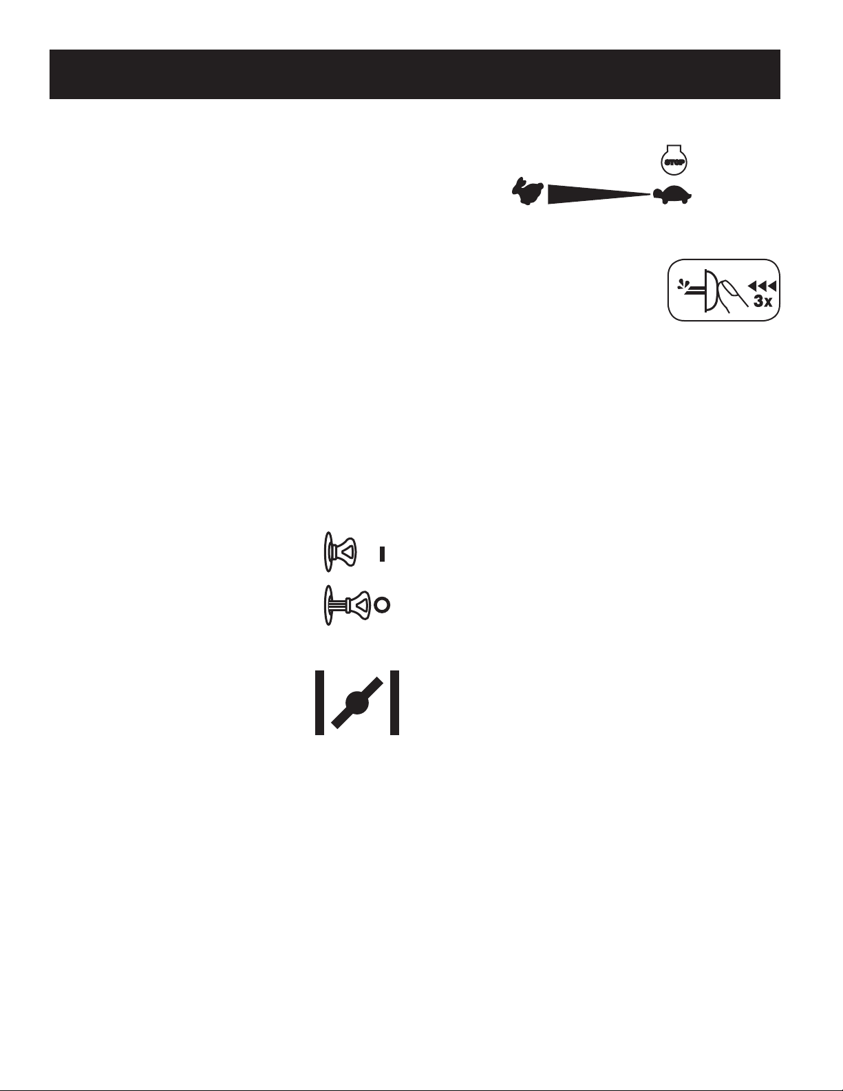
Shift Lever
The shift lever is located on the right side of the handle panel. Place the shift lever
into any of eight positions to control the direction of travel and ground speed.
Forward
Your snow thrower has six forward (F) speeds. Position one (1) is the slowest and
position six (6) is the fastest.
Reverse
Your snow thrower has two reverse (R) speeds. Position one (1) is the slower and
position two (2) is the faster.
Drift Cutters (If Equipped)
The drift cutters are designed for use in deep snow. Their use is optional for normal
snow conditions. Maneuver the snow thrower so that the cutters penetrate a high
standing snow drif t to assist snow falling into the augers for throwing.
Safety Key
The safety key is a safety device. It must be fully inserted in
order for the engine to start. Remove the safety key when
the snow thrower is not in use.
NOTE: Do not turn the safety key in an attempt to start the
engine. Doing so may cause it to break.
Throttle Control
The throttle control is located on the rear of the engine. It regulates the speed of the
engine and will shut off the engine when moved into the STOP position.
Primer
Depressing the primer forces fuel directly into the
engine’s carburetor to aid in cold-weather starting.
Electric Starter Button (If Equipped)
Pressing the electric starter button engages the engine’s electric starter when
plugged into a 120V power source.
Electric Starter Outlet (If Equipped)
Requires the use of a three-prong outdoor extension cord and a 120V power source/
wall outlet.
Oil Fill
Engine oil level can be checked and oil added through the oil fill.
Fuel Cap
Unthread the fuel cap to add gasoline to the fuel tank.
Auger
When engaged, the auger blades rotate and draw snow into the auger housing.
Chute Assembly
Choke Control
The choke control is found on the rear of the engine and is
activated by turning the rotary choke knob to the CHOKE
position. Activating the choke control closes the choke
plate on the carburetor and aids in starting the engine.
Recoil Starter Handle
This handle is used to manually start the engine.
LED Light (If Equipped)
The LED light is located inside of the handle panel and is ON when the engine is
running.
LED Light Bar (If Equipped)
The LED headlight is located on top of the auger housing and is automatically
turned ON when the engine is started.
Snow drawn into the auger housing is discharged out the chute assembly.
Skid Shoes
Position the skid shoes based on surface conditions. Adjust upward for hard-packed
snow. Adjust downward when operating on gravel or crushed rock surfaces.
Wheel Steering Controls (If Equipped)
The left and right wheel steering controls are located on the underside of the
handles. Squeeze the right control to turn right; squeeze the left control to turn left.
NOTE: Operate the snow thrower in open areas until you are familiar with these
controls.
22
OPERATION
Auger Control
AUGER
CONTROL
GO
The auger control is located on the left handle. Squeeze the control grip against the
handle to engage the auger and start snow throwing action. Release to stop.
IMPORTANT: Refer to the Auger Control information in the Assembly & Set-Up section
prior to operating your snow thrower. Read and follow all instructions carefully
and perform all adjustments to verify your snow thrower is operating safely and
properly.
Drive Control/ Auger Control Lock*
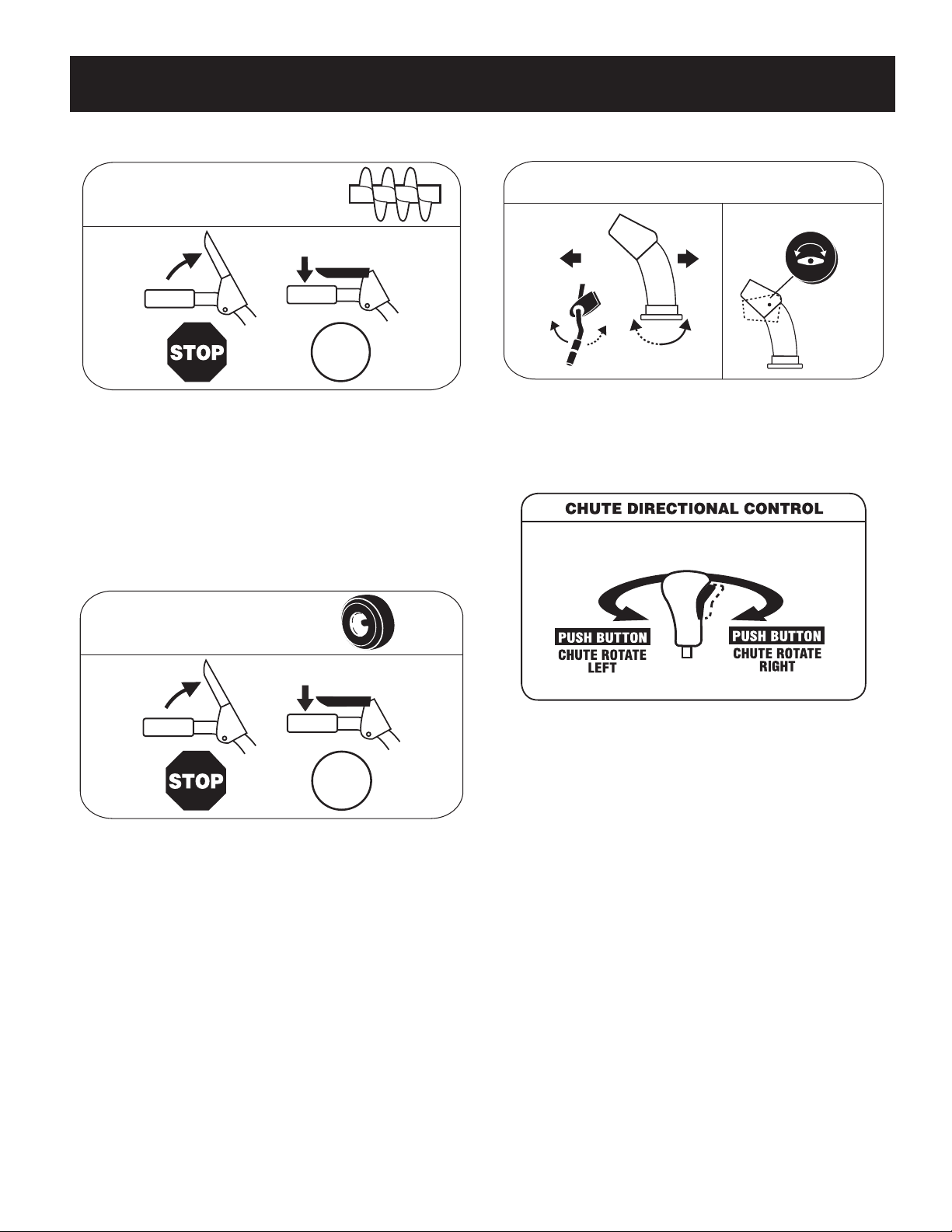
Overhead Chute Directional Control (If Equipped)
CHUTE DIRECTIONAL CONTROL
ADJUSTABLE
DISCHARGE
LEFT
The overhead chute directional control is located in the center of the snow thrower
between the handle panel and lower handle. To change the direction in which snow
is thrown, rotate the chute directional control.
DISCHARGE
RIGHT
CHUTE TILT
Two-Way Chute Control (If Equipped)
DRIVE
CONTROL
GO
The drive control is located on the right handle. Squeeze the control grip against the
handle to engage the wheel drive. Release to stop.
*On select models, the drive control also locks the auger control so you can operate
the chute directional control without interrupting the snow throwing process. If the
auger control is engaged simultaneously with the drive control, the operator can
release the auger control (on the lef t handle) and the augers will remain engaged.
Release both controls to stop the augers and wheel drive.
NOTE: Always release the drive control before changing speeds. Failure to do so will
result in increased wear on your machine’s drive system.
The two-way chute control (Joystick) is located on the left side of the handle panel.
• To change the direction in which snow is thrown, squeeze the button on the
chute control lever and pivot the chute control lever to the right or to the
left.
23
 Loading...