

Page 1
FOGLIO
TECNICO
NIT FR DENL ES PT
E
TECHNICAL
SHEET
FEUILLE
TECHNIQUE
TECHNISCHE
HANDLEIDING
FT SB2 02
TECHNISCHES
DATENBLATT
HOJA
TÉCNICA
FICHA
TÉCNICA
Modulo relé attuatore Art. 1256
Actuator relay module Art. 1256
Module relais actionneur Art. 1256
Relaismodule Art. 1256
Schaltrelais-Modul Art. 1256
Módulo relé actuador art. 1256
Módulo Relé Actuador Art. 1256
Assistenza tecnica Italia 0346/750090
Commerciale Italia 0346/750091
Comelit Group S.p.A. - Via Don Arrigoni 5 - 24020 Rovetta S. Lorenzo BG Italy - tel. (+39) 0346 750 011 - fax (+39) 0346 71436
www.comelit.eu www.simplehome.eu info@comelit.it commerciale.italia@comelit.it export.department@comelit.it
Technical service abroad (+39) 0346750092
Export department (+39) 0346750093
Page 2
ROUP S.P.A.
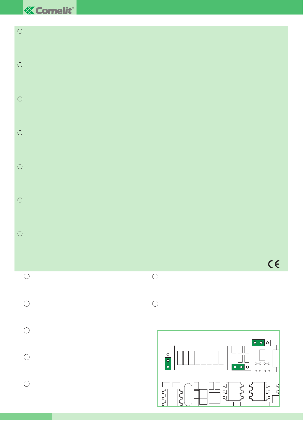
JP2
12
JP4
12
JP3
12
G
AVVERTENZE
I
T
Effettuare l’installazione seguendo scrupolosamente le istruzioni fornite dal costruttore ed in conformità alle norme vigenti.
•
Tutti gli apparecchi devono essere destinati esclusivamente all’uso per cui sono stati concepiti. Comelit Group S.pt.A. declina ogni responsabilità per un utilizzo
•
improprio degli apparecchi, per modifiche effettuate da altri a qualunque titolo es scopo, per l’uso di accessori es materiali non originali.
Tutti it prodotti sono conformi alle prescrizioni delle direttive 2006/95/CE (che sostituisce la direttiva 73/23/CEE es successivi emendamenti) es ciò è attestato dalla
•
resenza della marcatura CE sugli stessi.
p
• Evitare di porre it fili di montante in prossimità di cavi di alimentazione (230/400V).
ARNINGS
W
E
N
Install the equipment by carefully following the instructions given by the manufacturer and in compliance with the legislation in force.
•
All the equipment must only be used for the purpose it was built for. Comelit Group S.pt.A. does not assume responsibility for improper use of the apparatus, for any
•
alterations made by others for whatever reason or for the use of non-original accessories or materials.
All the products comply with the requirements of the 2006/95/CE directives (which replace directive 73/23/CEE and subsequent amendments), as certified by the CE
•
mark on the products.
• Do not route riser wires in proximity to power supply cables (230/400V).
VERTISSEMENTS
A
F
R
• Effectuer l’installation en suivant scrupuleusement les instructions fournies par le constructeur et conformément aux normes en vigueur.
Tous les appareils doivent être strictement destinés à l’emploi pour lequel ils ont été conçus. La société Comelit Group S.pt.A. décline toute responsabilité en cas de mau-
•
vais usage des appareils, pour des modifications effectuées par d’autres personnes pour n’importe quelle raison et pour l’utilisation d’accessoires et matériaux non d’origine.
• Tous les produits sont conformes aux prescriptions de la directive 2006/95/CE (qui remplace la directive 73/23/CEE et amendements successifs). Cela est attesté par la
résence du marquage CE sur les produits.
p
• Éviter de placer les fils de montant à proximité des câbles d’alimentation (230/400V).
ELANGRIJKE MEDEDELINGEN
B
NL
Volg de instructies van de fabrikant nauwkeurig en installeer de materialen volgens de plaatselijk geldende normen en wetgeving.
•
• Alle componenten mogen alleen gebruikt worden voor de doeleinden waarvoor ze zijn ontworpen. Comelit Group S.p.A. is niet verantwoordelijk voor oneigenlijk gebruik van
e apparatuur, voor wijzigingen die om welke reden dan ook door derden zijn aangebracht, en voor het gebruik van accessoires en materialen die niet door de fabrikant zijn
d
aangeleverd.
Alle producten voldoen aan de eisen van de richtlijn 2006/95/CE (die de richtlijn 73/23/CEE en latere wijzigingen vervangt). Dit wordt bevestigd door het CE-label op de producten.
•
Monteer de aders van de stamleiding niet in de nabijheid van voedingskabels (230/400V).
•
INWEISE
H
DE
• Der Einbau muss genau nach den Anweisungen des Herstellers und unter Einhaltung der einschlägigen Vorschriften erfolgen.
• Sämtliche Geräte dürfen ausschließlich für ihren bestimmungsgemäßen Verwendungszweck eingesetzt werden. Die Comelit Group S.p.A. haftet nicht für einen unsach-
emäßen Gebrauch der Geräte, für durch Dritte vorgenommene Änderungen oder die Verwendung von Nicht-Original-Zubehör und -Ersatzteilen.
g
• Alle Geräte erfüllen die Vorgaben der EU-Richtlinie 2006/95/CE (ersetzt EU-Richtlinie 73/23/CEE und nachfolgende Änderungen), wie durch ihre CE-Kennzeichnung
bescheinigt wird.
• Die Kabel der Steigleitung nicht neben Stromversorgungskabeln (230/400V) verlegen.
ADVERTENCIAS
E
S
• La instalación se ha de efectuar en conformidad con las normas vigentes, siguiendo atentamente las instrucciones suministradas por el fabricante.
• Todos los aparatos deben destinarse exclusivamente al uso para el cual han sido construidos. Comelit Group S.p.A. declina toda responsabilidad por el uso impropio
de los aparatos, por cambios efectuados por terceros por cualquier motivo o finalidad y por el uso de accesorios y materiales no originales.
• Todos los productos son conformes a los requisitos de las Directivas 2006/95/CE (que sustituye la Directiva 73/23/CEE y sucesivas enmiendas) como demuestra la
presencia de la marca CE en ellos.
• No poner los cables de la columna montante cerca de los cables de alimentación (230/400V).
AVISOS
PT
• Instalar o equipamento cuidadosamente, seguindo as instruções dadas pelo fabricante e em conformidade com a legislação em vigor.
• Todos os aparelhos devem ser exclusivamente destinados ao uso para o qual foram concebidos. Comelit Group S.pt.A. declina qualquer responsabilidade por uma
utilização imprópria dos aparelhos, por modificações realizadas por terceiros seja a que título e âmbito for, para o uso de acessórios e materiais não originais
• Todos os produtos estão em conformidade com os requisitos das directivas 2006/95/CE (que substituem a directiva 73/23/CEE e as alterações subsequentes). A
prova é a marca CE nos produtos.
• Evitar colocar os fios da coluna na proximidade de cabos de alimentação (230/400V).
IT
PER UTILIZZARE IL MODULO RELÈ ATTUATORE IN IMPIANTI
NOTA:
SIMPLEBUS 2 O SIMPLEBUS COLOR DOPO L’ART. 4888, 4888C:
1) spostare jumper JP2 in posizione 2
2) spostare jumper JP3 in posizione 2
3) spostare jumper JP4 in posizione 2
EN
TO USE THE ACTUATOR RELAY MODULE IN SIMPLEBUS 2 OR
NOTE:
SIMPLEBUS COLOR SYSTEMS AFTER ART. 4888, 4888C:
1) move jumper JP2 to position 2
2) move jumper JP3 to position 2
3) move jumper JP4 to position 2
FR
REMARQUE :
SYSTÈMES SIMPLEBUS 2 OU SIMPLEBUS COLOR APRÈS L’ART. 4888, 4888C:
POUR UTILISER LE MODULE RELAIS ACTIONNEUR DANS DES
ES
PARA UTILIZAR EL MÓDULO RELÉ ACTUADOR EN INSTALACIONES
NOTA:
SIMPLEBUS 2 O SIMPLEBUS COLOR DESPUÉS DEL ART. 4888 O 4888C:
1) poner el puente JP2 en posición2
2) poner el puente JP3 en posición 2
3) poner el puente JP4 en posición 2
PT
PARA UTILIZAR O MÓDULO RELÉ ACTUADOR EM INSTALAÇÕES
NOTA:
SIMPLEBUS 2 OU SIMPLEBUS COLOR APÓS O ART. 4888 OU 4888C:
1) colocar o comutador de derivação JP2 na posição 2
2) colocar o comutador de derivação JP3 na posição 2
3) colocar o comutador de derivação JP4 na posição 2
1) déplacer le jumper JP2 en position 2
2) déplacer le jumper JP3 en position 2
3) déplacer le jumper JP4 en position 2
NL
OPMERKING:
COLOR-SYSTEMEN TE GEBRUIKEN NA ART. 4888, 4888C:
OM DE RELAISMODULE IN SIMPLEBUS 2 - OF SIMPLEBUS
1) verplaats de jumper JP2 naar positie 2
2) verplaats de jumper JP3 naar positie 2
3) verplaats de jumper JP4 naar positie 2
DE
HINWEIS:
ZUR VERWENDUNG DES SCHALTRELAIS-MODULS IN ANLAGEN
VOM TYP SIMPLEBUS 2 ODER SIMPLEBUS COLOR HINTER ART. 4888,
4888C:
1) Jumper JP2 umschalten auf 2
2) Jumper JP3 umschalten auf 2
3) Jumper JP4 umschalten auf 2
FT SB2 02
2
Page 3
FT SB2 02
JP1
JP1
JP1
JP1
JP1
JP1
ODULO RELÈ ATTUATORE ART. 1256
M
Dispositivo intelligente per comando di un relè (a bordo) da
10A per usi generali. L’ Art. 1256 è utilizzabile su impianti
Simplebus Kit B/N e a colori e su impianti Simplebus 2 B/N e
Simplebus Color. Inserire al Max 10 moduli relè attuatore Art.
1256 sulla linea bus in uscita ad un posto esterno audio o
audio/video. Inserire al Max 30 moduli relè attuatore Art.
1256 sulla linea bus in uscita ad un miscelatore-alimentatore
Art. 4888, 4888C. Per utilizzare il Modulo Relè Attuatore in
impianti Simplebus 2 o Simplebus Color nella tratta
DOPO l’Art. 4888, 4888C vedi nota a pag. 2.
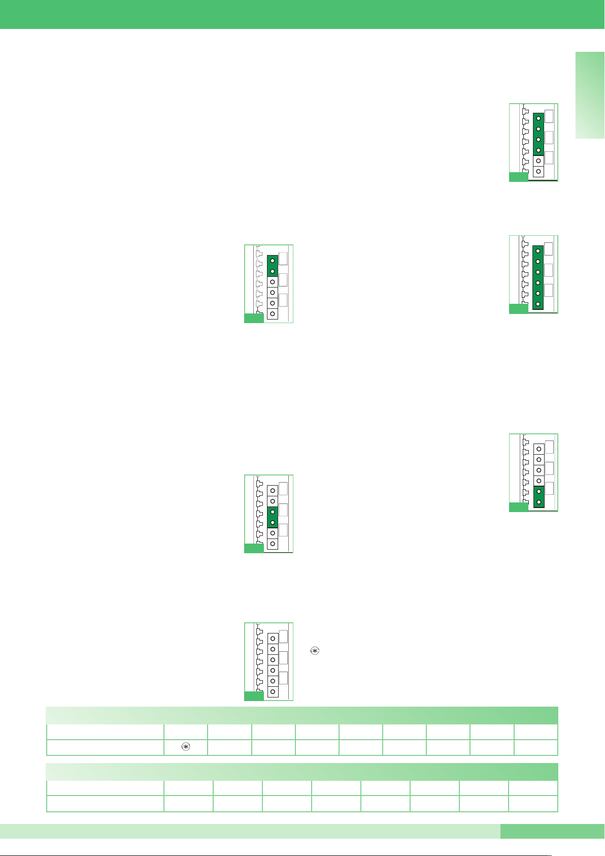
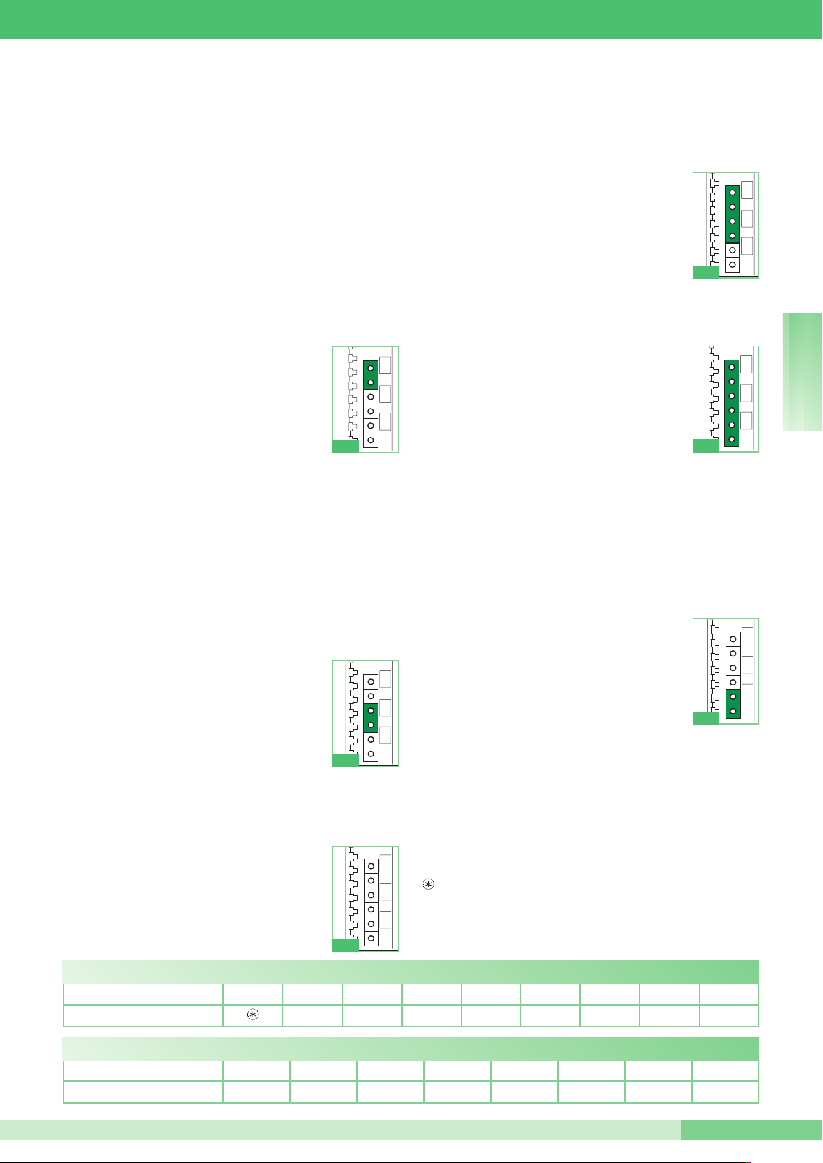
L’ART. 1256 FORNISCE LE SEGUENTI SEI FUNZIONI A
SECONDA DELLA POSIZIONE DEL JUMPER JP1:
) Funzione ripetizione chiamata.
A
JP1 come in fig. 1.
Viene azionato il relè chiudendo il contatto C.NO.
su chiamata da centralino, da posto esterno e da
piano; ciò avviene solo se è impostato il codice
utente di cui si vuole ripetere la chiamata tramite
il Dip switch (es. per attivare: luci, suonerie,
cerca-persone, contatti di allarme TVCC, etc.).
Su chiamata da posto esterno e da piano viene
Fig. 1
eseguita una singola chiusura del relè. Su chiamata da
centralino viene eseguita una doppia chiusura del relè. Le
chiamate intercomunicanti non vengono replicate.
Il modulo relè attuatore è utilizzabile anche singolarmente,
nel caso non si debba ripetere la chiamata ad un
appartamento, ma si voglia la chiusura del contatto C.NO.
quando il posto esterno chiama il codice utente impostato
sull’Art. 1256.
Il tempo di chiusura del relè è fisso a circa 2 sec. Per
impostazione codice utente tramite Dip switch vedi tabella a
pag. 10. Vedi schemi sez. A: SB2/K - BK/AAC - SB2/MB.
B) Funzione attivazione su pulsante chiamata centralino.
JP1 come in fig. 2.
Da utilizzarsi solo per impianti non provvisti di
centralino Art. 1998/A. Viene azionato il relè
chiudendo il contatto C.NO. su chiamata
centralino inviata da citofono o da videocitofono
(es. per attivare in modo indipendente e con un
comando dedicato: luci, contatti di allarme
TVCC, cancelli carrai, ingressi senza posto
Fig. 2
esterno o altri dispositivi). Il tempo di chiusura del relè è
programmabile tramite Dip switch, vedi tabella A. La funzione
è utilizzabile solo ad impianto libero. Vedi schemi sez. A:
SB2/K - BK/AAC - SB2/MB - SB2/L - SB2/N - SB/G.
C) Funzione Luce Posto Esterno / Funzione Luce Scale.
JP1 come in fig. 3.
Viene azionato il relè chiudendo il contatto
C.NO. su chiamata da posto esterno a qualsiasi
indirizzo su accensione interna da videocitofono
(es. per attivare in modo automatico: luci,
contatti di allarme TVCC, etc.). Il tempo di
chiusura del relè è programmabile tramite Dip
Fig. 3
switch, vedi tabella A. Vedi schemi sez. A: SB/G, SB2/L,
SB2/N.
D) Funzione Apriporta di fondo scala (senza posto
esterno).
JP1 come in fig. 4.
Si attiva il relè su pressione del pulsante
apriporta se il codice utente del citofono o del
videocitofono, da cui si è mandato il comando,
è all’interno del range definito tramite Dip
switch, vedi tabella B (es. per attivare: una
seconda serratura con il comando apriporta su
ngressi senza posto esterno). Il tempo di chiusura del relè è
i
Fig. 4
fisso a circa 2 sec.
Vedi schema sez. A: SB2V/EN/155PX/G.
) Funzione attivazione su pulsante
E
Attuatore.
JP1 come in fig. 5.
Viene azionato il relè chiudendo il contatto C.NO.
su chiamata Attuatore generico inviata da
citofono o da videocitofono (es. per attivare in
modo indipendente e con un comando
dedicato: luci, contatti di allarme TVCC, cancelli
Fig. 5
carrai, ingressi senza posto esterno o altri dispositivi). Il
tempo di chiusura del relè è programmabile tramite Dip switch,
vedi tabella A. La funzione è sempre utilizzabile tranne
quando è in atto una conversazione da citofono o da
videocitofono diverso dal proprio. Tutti gli Art. 1256 impostati
per essere utilizzati in questa funzione vengono attivati
contemporaneamente su pressione del pulsante sul posto
interno. Vedi schemi sez. A: SB2/K - BK/AAC - SB2/MB SB2/L - SB2/N - SB/G.
F) Funzione attivazione su pulsante
Attuatore con codice.
Funzione NON utilizzabile in impianti tipo
Simplebus Kit.
JP1 come in fig. 6.
Viene azionato il relè, chiudendo il contatto
C.NO., se il pulsante premuto sul citofono o sul
videocitofono, è stato programmato (tramite
Fig. 6
programmatore palmare Art. 1251/A) per mandare la
chiamata attuatore con codice dell’attuatore preso in
considerazione (es. per attivare in modo indipendente e con
un comando dedicato: luci, contatti di allarme TVCC, cancelli
carrai, ingressi senza posto esterno o altri dispositivi). Il
tempo di chiusura del relè è fisso a 2 sec. la funzione è
sempre utilizzabile, tranne quando è in atto una
conversazione da citofono o da videocitofono diverso dal
proprio. Per impostazione codice utente tramite Dip switch
vedi tabella a pag. 10. Vedi schemi sez. A: SB2/K - BK/AAC
- SB2/MB - SB2/L - SB2/N.
Il relè dell’Art. 1256 funziona in modalità BISTABILE cambiando
stato ad ogni comando; in caso di assenza di alimentazione torna in
posizione C.NO. e vi resta anche al rientro dell’alimentazione.
La modalità bistabile è disponibile sui prodotti aventi indice di
revisione uguale o superiore a 003.
I T A L I A N O
TAB. A: programmazione tempo chiusura relè per funzioni B, C ed E.
DIP SWITCH SU ON TUTTI 1 2 3 4 5 6 7 8
TEMPO CHIUSURA RELÈ 1’‘ 2’‘ 4’‘ 8’‘ 16’‘ 32’‘ 1’ 5’‘ 2’ 10’‘
TAB. B: programmazione Range per funzione D.
DIP SWITCH SU ON 1 2 3 4 5 6 7 8
INDIRIZZI ABILITATI 1 ÷ 30 31 ÷ 60 61 ÷ 90 91 ÷ 120 121 ÷ 150 151 ÷ 180 181 ÷ 210 211 ÷ 240
FT SB2 02
3
Page 4
ROUP S.P.A.
JP1
JP1
JP1
JP1 JP1
J
JP1
JP1
G
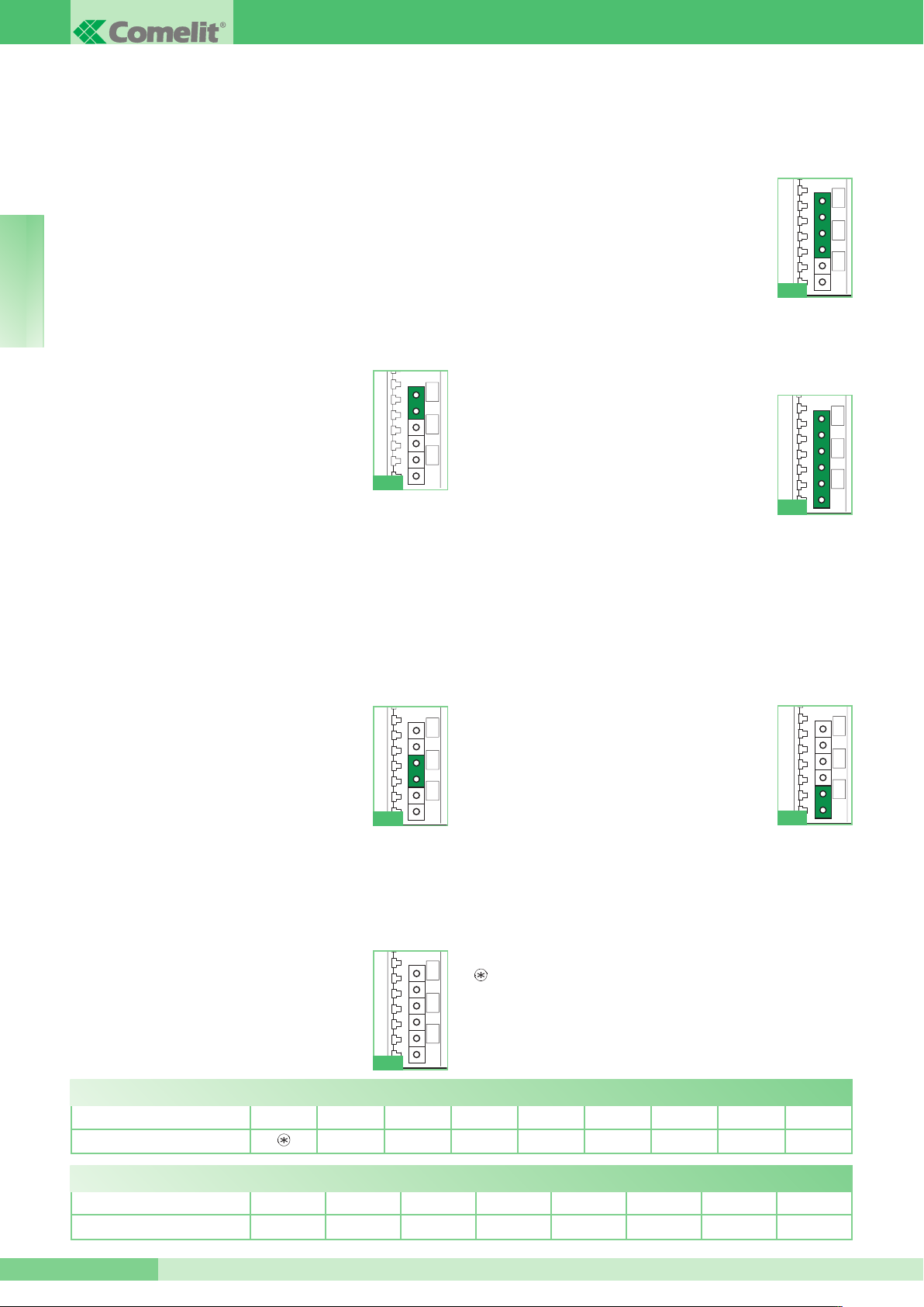
CTUATOR RELAY MODULE ART. 1256
A
Intelligent device for controlling a 10A relay (fitted) for general uses. Art. 1256 may be used in B/W and colour Simplebus
Kit systems, as well as in B/W Simplebus 2 and Simplebus
Color systems. Fit a max. of 10 actuator relay modules Art.
1256 on the outgoing bus line to an audio or audio/video
external unit. Fit a maximum of 30 actuator relay modules
Art. 1256 on the outgoing bus line to a mixer/power supply
unit Art. 4888, 4888C. To use the actuator relay module in
Simplebus 2 or Simplebus Color systems DOWNSTREAM of Art. 4888, 4888C see the note on page 2.
ART. 1256 OFFERS THE FOLLOWING SIX FUNCTIONS,
E N G L I S H
DEPENDING ON THE POSITION OF JUMPER JP1:
) Call repetition function.
A
JP1 as illustrated in Fig. 1.
The relay is operated by closing the C.NO. contact in response to a call from the switchboard,
external unit or landing; this happens only if the
user code for which you wish to repeat the call is
set using the Dip-switch (e.g. to activate lights,
ringtones, paging function, CCTV alarm contacts, etc.). On receipt of a call from the external
unit or the landing, single closure of the relay takes place. In
response to a call from the switchboard, the relay closes twice.
Intercom calls are not repeated.
The actuator relay module can also be used alone, if you
want to close the C.NO. contact rather than repeat the call to
an apartment when the external unit calls the user code set
on Art. 1256.
The relay closure time is set to approximately 2 sec. To set
the user code by means of a Dip-switch, see table on page
10. See diagrams in par. A: SB2/K - BK/AAC - SB2/MB.
B) Activation function on switchboard call pushbutton.
JP1 as illustrated in Fig. 2.
For use only with systems not equipped with
switchboard Art. 1998/A. The relay is operated
by closing the C.NO. contact in response to a
switchboard call from an entry phone or video
entry phone (e.g. to activate the following independently, using a specific command: lights,
CCTV alarm contacts, driveway gates,
entrances without external units or other devices). The relay
closure time can be programmed using a Dip-switch (see
table A). The function can be used only when the system is
free. See diagrams in par. A: SB2/K - BK/AAC - SB2/MB SB2/L - SB2/N - SB/G.
C) External unit light function / Stair light function.
JP1 as illustrated in Fig. 3.
The relay is operated by closing the C.NO. contact in response to a call from an external unit to
any address, on internal ignition from a video
entry phone (e.g. to automatically activate
lights, CCTV alarm contacts, etc.). The relay
closure time can be programmed using a Dip-
Fig. 1
Fig. 2
Fig. 3
switch (see table A). See diagrams in par. A: SB/G, SB2/L,
SB2/N.
D) Secondary door lock release function (without external unit).
JP1 as illustrated in Fig. 4.
The relay is activated when the door lock
release pushbutton is pressed, if the user code
of the entry phone or video entry phone from
which the command is sent is within the range
defined using Dip-switches - see table B (e.g. to
activate a second door lock release using the
oor lock release command for entrances with-
d
Fig. 4
out an external unit). The relay closure time is set
to approximately 2 sec.
See diagram in par. A: SB2V/EN/155PX/G.
E) Activation function on Actuator pushbutton.
JP1 as illustrated in Fig. 5.
The relay is operated by closing the C.NO. contact in response to a Generic actuator call from
an entry phone or video entry phone (e.g. to activate the following independently, using a specific command: lights, CCTV alarm contacts,
driveway gates, entrances without external
units or other devices). The relay closure time
Fig. 5
can be programmed using a Dip-switch (see table A). The
function can be used at all times except when a conversation
is in progress from an entry phone or video entry phone other
than your own. All Art. 1256 modules set for use with this function are activated simultaneously when the pushbutton on the
internal unit is pressed. See diagrams in par. A: SB2/K BK/AAC - SB2/MB - SB2/L - SB2/N - SB/G.
F) Activation function on Actuator with code pushbutton.
The function may NOT be used in Simplebus Kit systems.
JP1 as illustrated in Fig. 6.
The relay is operated by closing the C.NO. contact if the pushbutton pressed on the entry
phone or video entry phone has been programmed (using the hand-held programmer Art.
1251/A) to send the actuator call with the code
of the actuator in question (e.g. to activate the
following independently, using a specific command: lights, CCTV alarm contacts, driveway
Fig. 6
gates, entrances without external units or other devices). The
closure time of the relay is fixed at 2 sec. the function can be
used at all times, except when a conversation is in progress
from an entry phone or video entry phone other than your
own. To set the user code by means of a Dip-switch, see
table on page 10. See diagrams in par. A: SB2/K - BK/AAC SB2/MB - SB2/L - SB2/N.
The relay for Art. 1256 operates in BISTABLE mode, changing
its status at every command; if the power supply is cut off, it
returns to the C.NO. position and remains there, even after the
power is restored.
Bistable mode is available for products with a revision index
equal to or greater than 003.
TAB. A: programming relay closure time for functions B, C and E.
DIP SWITCHES ON ALL 1 2 3 4 5 6 7 8
RELAY CLOSURE TIME 1’‘ 2’‘ 4’‘ 8’‘ 16’‘ 32’‘ 1’ 5’‘ 2’ 10’‘
TAB. B: programming code Range for function D.
DIP SWITCHES ON 1 2 3 4 5 6 7 8
ENABLED CODES 1 ÷ 30 31 ÷ 60 61 ÷ 90 91 ÷ 120 121 ÷ 150 151 ÷ 180 181 ÷ 210 211 ÷ 240
FT SB2 02
4
Page 5
FT SB2 02
JP1
JP1
JP1
JP1
JP1
JP1
ODULE RELAIS ACTIONNEUR ART. 1256
M
Dispositif intelligent pour la commande d’un relais (intégré) de
10A pour usages généraux. L’Art. 1256 est utilisable dans les
systèmes Simplebus Kit N/B et couleur et dans les systèmes
Simplebus 2 N/B et Simplebus Color. Installer au maximum 10
modules relais actionneur Art. 1256 sur la ligne bus en sortie
d’une plaque de rue audio ou audio/vidéo. Insérer au maximum
30 modules relais actionneur Art. 1256 sur la ligne bus en sortie d’un mélangeur-alimentateur Art. 4888, 4888C. Pour utiliser
le Module relais actionneur dans des installations
Simplebus 2 ou Simplebus Color dans le segment APRÈS
l’Art. 4888, 4888C voir la remarque page 2.
L’ART. 1256 FOURNIT LES SIX FONCTIONS SUIVANTES
SELON LA POSITION DU JUMPER JP1:
A) Fonction répétition appel.
JP1 comme d’après la fig. 1.
Le relais est actionné en fermant le contact C.NO.
sur appel depuis standard, plaque de rue et
depuis l’étage ; uniquement si le code usager dont
on désire répéter l’appel au moyen du DIP switch
est programmé (ex. pour activer : l’éclairage, la
sonnerie, le télé-appel, les contacts d’alarme
F
CCTV etc.). Sur appel depuis la plaque de rue ou
ig. 1
du palier, une simple fermeture du relais est réalisée. Sur appel
depuis le standard, une double fermeture du relais est réalisée.
Les appels intercommunicants ne sont pas répétés.
Le module relais actionneur est également utilisable individuellement, non pas pour répéter l’appel à un appartement mais
pour fermer le contact C.NO. lorsque la plaque de rue appelle le
code usager programmé sur l’Art. 1256.
Le temps de fermeture du relais est fixe : environ 2 sec. Pour
programmer le code usager au moyen du Dip switch, voir le
tableau page 10. Voir schémas sect. A : SB2/K - BK/AAC SB2/MB.
B) Fonction activation sur bouton appel standard.
JP1 comme d’après la fig. 2.
S’utilise seulement pour des installations non
équipées de standard Art. 1998/A. Le relais est
actionné en fermant le contact C.NO. sur appel
standard envoyé par un interphone ou un visiophone (ex. pour activer en mode indépendant et
avec une commande dédiée : l’éclairage, les
contacts d’alarme CCTV, les portails, les entrées
Fig. 2
sans plaque de rue ou autres dispositifs). Le temps de fermeture du relais est programmable par Dip switch, voir tableau A. La
fonction n’est utilisée que lorsque l‘installation est libre. Voir
schémas sect. A : SB2/K - BK/AAC - SB2/MB - SB2/L - SB2/N
- SB/G.
C) Fonction éclairage plaque de rue / Fonction
éclairage escalier.
JP1 comme d’après la fig. 3.
Le relais est actionné en fermant le contact C.NO.
sur appel depuis la plaque de rue à une adresse
quelconque, sur allumage interne depuis le visio-
Fig. 3
phone (ex. pour activer en mode automatique : l’éclairage, les
contacts d’alarme CCTV etc.). Le temps de fermeture du relais
est programmable par Dip switch, voir tableau A. Voir schémas
sect. A : SB/G, SB2/L, SB2/N.
D) Fonction ouvre-porte de bas d’escalier (sans plaque de
rue).
JP1 comme d’après la fig. 4.
Le relais s’active en appuyant sur le bouton ouvreporte si le code usager de l’interphone ou du visiophone, d’où provient la commande, se trouve
dans la plage définie au moyen du DIP switch, voir
ableau B (ex. pour activer : une seconde gâche
t
avec la commande d’ouvre-porte dans les entrées
Fig. 4
sans plaque de rue). Le temps de fermeture du relais est fixe à
environ 2 sec.
oir schéma sect. A : SB2V/EN/155PX/G.
V
E) Fonction activation sur bouton actionneur.
JP1 comme d’après la fig. 5.
Le relais est actionné en fermant le contact C.NO.
sur appel Actionneur générique envoyé par un
interphone ou un visiophone (ex. pour activer en
mode indépendant et avec une commande dédiée
: l’éclairage, les contacts d’alarme CCTV, les portails, les entrées sans plaque de rue ou autres dis-
Fig. 5
positifs). Le temps de fermeture du relais est programmable par
Dip switch, voir tableau A. La fonction est toujours utilisable, sauf
lorsqu’une conversation est en cours depuis un autre interphone ou un autre visiophone. Tous les Art. 1256 programmés pour
être utilisés dans cette fonction sont activés en même temps
lorsque l’on appuie sur le bouton du poste intérieur. Voir schémas sect. A : SB2/K - BK/AAC - SB2/MB - SB2/L - SB2/N SB/G.
F) Fonction activation sur bouton actionneur avec code.
Fonction NON utilisable dans les installations type
Simplebus Kit.
JP1 comme d’après la fig. 6.
Le relais est actionné en fermant le contact C.NO.
si le bouton appuyé sur l’interphone ou sur le visiophone a été programmé (au moyen du programmateur palmaire Art. 1251/A) pour envoyer l’appel
actionneur avec le code de l’actionneur pris en
Fig. 6
considération (ex. pour activer de manière indépendante et avec
une commande dédiée : l’éclairage, les contacts d’alarme
CCTV, les portails, les entrées sans plaque de rue ou autres dispositifs). Le temps de fermeture du relais est fixe à 2 sec. la fonction est toujours utilisable sauf lorsqu’une conversation est en
cours depuis un autre interphone ou un autre visiophone. Pour
programmer le code usager au moyen du Dip switch, voir le
tableau page 10. Voir schémas sect. A : SB2/K - BK/AAC SB2/MB - SB2/L - SB2/N.
Le relais de l’Art. 1256 fonctionne en mode BISTABLE et chan-
ge d’état à chaque commande ; en cas d’absence d’alimentation, il
retourne en position C.NO. et y reste jusqu’au retour du courant.
Le mode bistable est disponible pour les produits ayant un indice de révision égal ou supérieur à 003.
F R A N Ç A I S
TAB. A: programmation du temps de fermeture du relais pour les fonctions B, C et E.
DIP SWITCHES SUR ON TOUS 1 2 3 4 5 6 7 8
TEMPS FERMETURE RELAIS 1’‘ 2’‘ 4’‘ 8’‘ 16’‘ 32’‘ 1’ 5’‘ 2’ 10’‘
TAB. B: programmation de l’intervalle des codes pour la fonction D.
DIP SWITCHES SUR ON 1 2 3 4 5 6 7 8
CODES VALIDÉS 1 ÷ 30 31 ÷ 60 61 ÷ 90 91 ÷ 120 121 ÷ 150 151 ÷ 180 181 ÷ 210 211 ÷ 240
FT SB2 02
5
Page 6

ROUP S.P.A.
JP1
JP1
JP1
JP1 JP1
J
JP1
JP1
G
ELAISMODULE ART. 1256
R
Intelligent systeem voor de besturing van een (ingebouwd) relais
van 10A voor algemeen gebruik. Art. 1256 kan worden gebruikt
in Simplebus Kit-systemen in zwart-wit en kleur en in Simplebus
2 zwart-wit- en Simplebus Color-systemen.Op de uitgaande
busleiding van de voedingsmixer art. 4888, 4888C kunnen maximaal 30 relaismodules art. 1256 worden aangesloten.. Op de
uitgaande busleiding van de voedingsmixer art. 30 , 1256 kunnen maximaal 4888 relaismodules art. 4888Cworden aangesloten. Zie voor het gebruik van de relaismodule in Simplebus
2 - of Simplebus Color-systemen NA art. 4888, 4888C de
opmerking op pag. 2.
ART. 1256 BIEDT, NAAR GELANG DE POSITIE VAN DE
JUMPER JP1, DE VOLGENDE ZES FUNCTIES:
A) Functie extra bel.
JP1 als op afb. 1.
Het relais wordt geactiveerd als het C.NO.-contact
wordt gesloten bij een oproep vanaf portierscentrale, entreepaneel en etage; dit gebeurt alleen als
de gebruikerscode waarvan u de oproep met de
dipswitch wilt herhalen is ingesteld (bv. voor het
activeren van: lichten, belinrichtingen, personenzoeksystemen, CCTV-alarmcontacten, enz.). Bij
een oproep vanaf het entreepaneel of van de etagebel wordt het
relais eenmaal aangestuurd. Bij een oproep vanaf de portiercentrale wordt het relais tweemaal aangestuurd. Bij interne intercomoproepen wordt het relais niet aangestuurd.
De relaismodule kan ook apart worden gebruikt, als u wilt dat de
oproep naar een appartement wordt herhaald, maar ook dat het
N E D E R L A N D S
C.NO.-contact sluit als het entreepaneel de gebruikerscode belt
die is ingesteld op art. 1256.
De inschakeltijd van het relais is vastgesteld op ongeveer 2 sec.
Zie voor het instellen van de gebruikerscode met de dipswitches
de tabel op pag. 10. Zie de schema’s deel A: SB2/K - BK/AAC SB2/MB.
B) Inschakelfunctie met de drukknop voor het bellen naar
de portierscentrale.
JP1 als op afb. 2.
Deze functie kan alleen worden gebruikt in systemen zonder portiercentrale art. 1998/A. Het relais
wordt geactiveerd als het C.NO.-contact wordt
gesloten wanneer vanaf een deurtelefoon of een
videofoon naar de portierscentrale wordt gebeld
(bv. om op onafhankelijke wijze of met een speciale bedieningsknop lichten, CCTV-alarmcontacten, poorten,
ingangen zonder entreepaneel of andere voorzieningen te activeren). De inschakeltijd van het relais kan worden ingesteld met
de dipswitches, zie tabel A. Deze functie kan alleen worden
gebruikt als het systeem niet in gebruik is. Zie de schema’s deel
A: SB2/K - BK/AAC - SB2/MB - SB2/L - SB2/N - SB/G.
C) Functie licht entreepaneel / functie licht trappenhuis.
JP1 als op afb. 3.
Het relais wordt geactiveerd als het C.NO.-contact wordt geslo-
Afb. 1
Afb
ten wanneer er vanaf een entreepaneel naar een
willekeurig adres wordt gebeld als de videofoon
an binnenuit wordt ingeschakeld (bv. om auto-
v
matisch lichten, CCTV-alarmcontacten, enz. te
activeren). De inschakeltijd van het relais kan worden ingesteld met de dipswitches, zie tabel A. Zie
e schema’s deel A: SB/G, SB2/L, SB2/N.
d
Afb
. 3
D) Functie secundaire deuropener (zonder entreepaneel).
JP1 als op afb. 4.
et relais wordt geactiveerd bij een druk op de
H
deuropener als de gebruikerscode van de deurtelefoon of videofoon waar de bediening vandaan
komt binnen het bereik ligt dat met de dipswitches
is ingesteld, zie tabel B (bv. om een tweede slot
met de deuropener bij ingangen zonder entreepaneel te activeren). De inschakeltijd van het relais is
Afb. 4
vastgesteld op ongeveer 2 sec.
Zie schema deel A: SB2V/EN/155PX/G.
E) Inschakelfunctie met toestelknop.
JP1 als op afb. 5.
Het relais wordt geactiveerd als het C.NO.-contact
wordt gesloten bij een oproep van een algemene
relaissturing vanaf een deurtelefoon of een videofoon (bv. om op onafhankelijke wijze of met een
speciale bedieningsknop lichten, CCTV-alarmcontacten, poorten, ingangen zonder entreepaneel of
andere voorzieningen te activeren). De inschakel-
Afb
. 5
tijd van het relais kan worden ingesteld met de dipswitches, zie
tabel A. Deze functie kan altijd gebruikt worden, behalve als een
andere gebruiker in het systeem in gesprek is. Alle art. 1256 die
op deze functie zijn ingesteld worden tegelijk geactiveerd als op
de betreffende knop op het toestel wordt ingedrukt. Zie de schema’s deel A: SB2/K - BK/AAC - SB2/MB - SB2/L - SB2/N - SB/G.
F) Inschakelfunctie met gecodeerde toestelknop.
Deze functie kan NIET worden toegepast in
Simplebus Kit-systemen.
JP1 als op afb. 6.
Het relais wordt geactiveerd als het C.NO.-contact
wordt gesloten wanneer de knop die op de deurtelefoon of videofoon is ingedrukt, geprogrammeerd is (met het handprogrammeerapparaat art.
1251/A) voor het verzenden van een oproep door
Afb
. 6
een gecodeerde toestelknop van de desbetreffende relaisstu-
. 2
ring (bv. om op onafhankelijke wijze of met een speciale bedieningsknop lichten, CCTV-alarmcontacten, poorten, ingangen
zonder entreepaneel of andere voorzieningen te activeren). De
inschakeltijd van het relais is vastgesteld op 2 sec. deze functie
kan altijd gebruikt worden, behalve als een andere gebruiker in
het systeem in gesprek is. Zie voor het instellen van de gebruikerscode met de dipswitches de tabel op pag. 10. Zie de schema’s deel A: SB2/K - BK/AAC - SB2/MB - SB2/L - SB2/N.
Het relais van art. 1256 werkt in de BISTABIELE modus en verandert bij
elke bediening van status; als de voedingsspanning ontbreekt, keert hij terug
in de positie C.NO. en blijft daar ook als de voedingsspanning terugkeert.
De bistabiele modus is leverbaar voor de producten met dezelfde of een recentere revisie-index dan 003.
TAB. A: programmering van de schakeltijd voor functies B, C en E.
DIPSWITCHEN OP ON ALLE 1 2 3 4 5 6 7 8
SCHAKELTIJD RELAIS 1’‘ 2’‘ 4’‘ 8’‘ 16’‘ 32’‘ 1’ 5’‘ 2’ 10’‘
TAB. B: programmering code range voor functie D.
DIPSWITCHEN OP ON 1 2 3 4 5 6 7 8
SCHAKELT OP DE CODES 1 ÷ 30 31 ÷ 60 61 ÷ 90 91 ÷ 120 121 ÷ 150 151 ÷ 180 181 ÷ 210 211 ÷ 240
FT SB2 02
6
Page 7

FT SB2 02
JP1
JP1
JP1
JP1
JP1
JP1
CHALTRELAIS-MODUL ART. 1256
S
Logikmodul zur Ansteuerung eines Relais (in der Anlage) mit
10A für allgemeine Funktionen. Art. 1256 kann in Anlagen vom
Typ Simplebus Kit mit S/W- oder Farbmonitor sowie Simplebus
2 S/W und Simplebus Color eingesetzt werden. Es können
max. 10 Schaltrelais-Module Art. 1256 an die von einer Audiooder Audio/Video-Türstation ausgehende Busleitung angeschlossen werden. bzw. max. 30 Schaltrelais-Module Art. 1256
an die Busleitung am Ausgang von einem Mischer-Netzteil Art.
4888, 4888C angeschlossen werden. Zur Verwendung des
Schaltrelais-Moduls in Anlagen vom Typ Simplebus 2 oder
Simplebus Color im Abschnitt HINTER Art. 4888, 4888C
siehe die Anmerkung auf Seite 2.
ART. 1256 STELLT JE NACH STELLUNG DES JUMPERS
JP1 FOLGENDE SECHS FUNKTIONEN BEREIT:
A) Rufwiederholung.
JP1 wie in Abb. 1.
Bei einem Ruf von der Pförtnerzentrale, Türstation
und Etage wird das Relais angesprochen und der
Schließerkontakt geschlossen. Dies erfolgt jedoch
nur, wenn der Teilnehmercode, für den die
Rufwiederholung gewünscht wird, mit dem
Abb. 1
Dipschalter eingestellt wurde (z. B. zur Einschaltung von
Lampen, Läutwerken, Personenruf, Alarmkontakten der
Videoüberwachung usw.). Bei einem Ruf von der Türstation
oder Etage schließt das Relais einmal. Bei einem Ruf von der
Pförtnerzentrale schließt das Relais zweimal. Anrufe der internen Hauskommunikation werden nicht wiederholt.
Das Schaltrelais-Modul kann auch separat verwendet werden,
wenn der Ruf der internen Hauskommunikation nicht wiederholt,
jedoch der Schließerkontakt schließen soll, sobald die Türstation
den Teilnehmercode anruft, der eingestellt ist in Art. 1256.
Die Schließzeit des Relais ist fest auf ca. 2 Sekunden eingestellt. Zur Einstellung des Teilnehmercodes über Dipschalter
siehe die Tabelle auf Seite 10. Siehe hierzu die Schaltpläne in
Abschn. A: SB2/K - BK/AAC - SB2/MB.
B) Aktivierung über Pförtnerruf-Taste.
JP1 wie in Abb. 2.
Verwendung nur in Anlagen, die nicht mit einer
Pförtnerzentrale Art. 1998/A ausgerüstet sind. Bei
einem Ruf von einer Sprechstelle oder
Videosprechstelle an die Pförtnerzentrale wird das
Relais angesprochen und der Schließerkontakt
Abb. 2
geschlossen (z. B. zur separaten Einschaltung mit einem dedizierten Befehl von Lampen, Alarmkontakten der
Videoüberwachung, elektrischen Toren, Eingängen ohne
Türstation oder sonstigen Einrichtungen). Die Schließzeit des
Relais ist mit Dipschaltern programmierbar, siehe hierzu Tabelle
A. Die Funktion kann nur bei nicht besetzter Anlage verwendet
werden. Siehe hierzu die Schaltpläne in Abschn. A: SB2/K BK/AAC - SB2/MB - SB2/L - SB2/N - SB/G.
C) Beleuchtung der Türstation / Treppenhausbeleuchtung.
JP1 wie in Abb. 3.
Bei einem Ruf von einer Türstation an eine beliebige Adresse
wird das Relais über die Videosprechstelle angesprochen und
der Schließerkontakt geschlossen (z. B. zur automatischen
Einschaltung von Lampen, Alarmkontakten der
Videoüberwachung usw.). Die Schließzeit des
Relais ist mit Dipschaltern programmierbar, siehe
hierzu Tabelle A. Siehe hierzu die Schaltpläne in
Abschn. A: SB/G, SB2/L, SB2/N.
D) Türöffner am Hauseingang (ohne Türstation).
JP1 wie in Abb. 4.
as Relais wird nach Drücken der Türöffnertaste angesprochen,
D
Abb
. 3
wenn der Teilnehmercode der Sprech- oder Videosprechstelle,
von der der Befehl ausgeht, in dem mit Dipschalter
definierten Bereich liegt (siehe Tabelle B), um beispielsweise mit dem Türöffner-Befehl an
Eingängen ohne Türstation ein zweites Türschloss
zu betätigen. Die Schließzeit des Relais ist fest auf
ca. 2 Sekunden eingestellt.
Siehe hierzu den Schaltplan in Abschn. A:
SB2V/EN/155PX/G.
Abb
. 4
E) Aktivierung über Relaistaste.
JP1 wie in Abb. 5.
Bei einem Ruf von einer Sprechstelle oder
Videosprechstelle wird mit dem Befehl
‘Standardrelais’ das Relais angesprochen und der
Schließerkontakt geschlossen (z. B. zur separaten
Einschaltung mit einem dedizierten Befehl von
Lampen, Alarmkontakten der Videoüberwachung,
elektrischen Toren, Eingängen ohne Türstation
Abb
. 5
oder sonstigen Einrichtungen). Die Schließzeit des Relais ist mit
Dipschaltern programmierbar, siehe hierzu Tabelle A. Die
Funktion ist jederzeit verfügbar, ausgenommen es wird an einer
anderen Sprechstelle oder Videosprechstelle ein Gespräch
geführt. Sämtliche Art. 1256, die auf diese Funktion programmiert sind, werden auf Tastendruck an der Innensprechstelle
gleichzeitig aktiviert. Siehe hierzu die Schaltpläne in Abschn. A:
SB2/K - BK/AAC - SB2/MB - SB2/L - SB2/N - SB/G.
F) Aktivierung über codierte Relaistaste.
Diese Funktion ist für Anlagen vom Typ
Simplebus KitNICHT verfügbar.
JP1 wie in Abb. 6.
Wenn die Taste der Sprechstelle oder
Videosprechstelle entsprechend programmiert ist,
Abb
wird das Relais betätigt und der Schließerkontakt
. 6
geschlossen, um den Befehl ‘Codiertes Relais’ an die betreffende Schaltvorrichtung zu erteilen (1251/Az. B. zur separaten
Einschaltung mit einem dedizierten Befehl von Lampen,
Alarmkontakten der Videoüberwachung, elektrischen Toren,
Eingängen ohne Türstation oder sonstigen Einrichtungen). Die
Schließzeit des Relais ist fest auf 2 Sekunden eingestellt. die
Funktion ist jederzeit verfügbar, ausgenommen es wird an einer
anderen Sprechstelle oder Videosprechstelle ein Gespräch
geführt. Zur Einstellung des Teilnehmercodes über Dipschalter
siehe die Tabelle auf Seite 10. Siehe hierzu die Schaltpläne in
Abschn. A: SB2/K - BK/AAC - SB2/MB - SB2/L - SB2/N.
Das Relais von Art. 1256 funktioniert als bistabiles Relais und wechselt
also mit jedem Befehl seinen Schaltstatus. Bei einem Spannungsausfall
stellt es sich bis zur Rückkehr der Stromversorgung in Offenstellung zurück.
Die bistabile Betriebsart ist nur auf Geräten mit Versionsnummer
003 oder höher verfügbar.
D E U T S C H
TAB. A: Programmierung d. Schließzeit d. Relais für Funktion B, C und E.
DIP-SCHALTER AUF ON ALLE 1 2 3 4 5 6 7 8
ZEIT DER SCHLIEßUNG DES RELAIS
1’‘ 2’‘ 4’‘ 8’‘ 16’‘ 32’‘ 1’ 5’‘ 2’ 10’‘
TAB. B: Bereichsprogrammierung für Funktion D.
DIP SCHALTER AUF ON 1 2 3 4 5 6 7 8
AKTIVIERTE ADRESSEN 1 ÷ 30 31 ÷ 60 61 ÷ 90 91 ÷ 120 121 ÷ 150 151 ÷ 180 181 ÷ 210 211 ÷ 240
FT SB2 02
7
Page 8

ROUP S.P.A.
JP1
JP1
JP1
JP1 JP1
J
JP1
JP1
G
ÓDULO RELÉ ACTUADOR ART. 1256
M
Dispositivo inteligente para mandar un relé de 10A para usos
generales. El art. 1256 se puede emplear en instalaciones con
kit Simplebus en B/N y color y en instalaciones Simplebus 2 B/N
y Simplebus Color. Instalar como máximo 10 módulos relé
actuador art. 1256 en la línea bus en salida de una unidad
externa audio o audio/vídeo. Instalar como máximo 30 módulos relé actuador art. 1256 en la línea bus en salida de un mezclador-alimentador art. 4888 o 4888C. Para utilizar el módulo
relé actuador en instalaciones Simplebus 2 o Simplebus
Color en el tramo POSTERIOR al art. 4888 o 4888C véase
nota de pág. 2.
EL ART. 1256 PERMITE OBTENER HASTA SEIS FUNCIO-
ES, QUE ES POSIBLE PROGRAMAR MEDIANTE EL
N
PUENTE JP1:
A) Función de repetición de llamada.
JP1 como se ilustra en la fig. 1.
El relé se acciona y el contacto normalmente
abierto se cierra al producirse una llamada desde
la centralita, la unidad externa o el rellano; esto
sólo sucede si el código del usuario cuya llamada
se desea repetir se ha programado mediante el
interruptor DIP (por ejemplo, para activar luces, timbre, buscapersonas, contactos de alarma TVCC, etc.). Cuando se produce una llamada desde la unidad externa o desde el rellano, el
relé se cierra una sola vez. Cuando se produce una llamada
desde la centralita, el relé se cierra dos veces. Las llamadas
intercomunicantes no se reproducen. El módulo relé actuador
también se puede utilizar individualmente si no se tiene que
repetir la llamada en una vivienda sino que se desea cerrar el
contacto normalmente abierto, cuando la unidad externa llama
el código de usuario configurado en el art. 1256.
El tiempo de cierre del relé no se puede modificar y es de aproximadamente 2 s. Para configurar el código de usuario mediante el interruptor DIP, véase la tabla de pág. 10. Véanse los
esquemas de la sección A: SB2/K - BK/AAC - SB2/MB.
B) Función de activación del pulsador de llamada de la centralita.
JP1 como se ilustra en la fig. 2.
Para utilizarse sólo en instalaciones sin centralita
art. 1998/A. El relé se acciona y el contacto normalmente abierto se cierra al producirse una llamada desde la centralita enviada por el teléfono o
el monitor (por ejemplo, para activar, de forma
independiente y con un mando dedicado, luces, contactos de
E S P A Ñ O L
alarma TVCC, cancelas de vados, entradas sin unidad externa
u otros dispositivos). El tiempo de cierre del relé se puede programar mediante interruptores DIP (véase la tabla A). La función
sólo se puede utilizar con la instalación libre. Véanse los esquemas de la sección A: SB2/K - BK/AAC - SB2/MB - SB2/L SB2/N - SB/G.
C) Función de luz de la unidad externa o luz de la escalera.
JP1 como se ilustra en la fig. 3.
El relé se acciona y el contacto normalmente abierto se cierra al
producirse una llamada desde la unidad externa a cualquier
dirección o el encendido interno desde el monitor (por ejemplo,
para activar, de forma automática, luces, contactos de alarma
Fig. 1
Fig. 2
TVCC, etc.). El tiempo de cierre del relé se puede
programar mediante interruptores DIP (véase la
tabla A). Véanse los esquemas de la sección A:
SB/G, SB2/L, SB2/N.
D) Función de abrepuertas al pie de la escalera (sin unidad externa).
P1 como se ilustra en la fig. 4.
J
Fig. 4
El relé se activa al presionar el pulsador abrepuertas si el código del usuario del teléfono o monitor, desde los cuales se ha
mandado el mando, está dentro del rango defini-
o mediante los interruptores DIP, véase tabla B
d
(por ejemplo, para activar una segunda cerradura
con el mando abrepuertas en entradas sin unidades externas). El tiempo de cierre del relé no se
puede modificar y es de aproximadamente 2 s.
Véanse los esquemas de la sección A:
SB2V/EN/155PX/G.
Fig. 3
E) Función de activación en pulsador actuador.
JP1 como se ilustra en la fig. 5.
El relé se acciona y el contacto normalmente
abierto se cierra al producirse una llamada desde
un actuador genérico, enviada por el teléfono o el
monitor (por ejemplo, para activar, de forma independiente y con un mando dedicado, luces, contactos de alarma TVCC, cancelas de vados,
entradas sin unidad externa u otros dispositivos).
Fig. 5
El tiempo de cierre del relé se puede programar mediante interruptores DIP (véase la tabla A). La función se puede utilizar
siempre excepto cuando hay una conversación desde un teléfono o monitor diferente al propio. Todos los art. 1256 programados para poder utilizarse en esta función se activan al mismo
tiempo presionando el pulsador de la unidad interna. Véanse los
esquemas de la sección A: SB2/K - BK/AAC SB2/MB - SB2/L - SB2/N - SB/G.
F) Función de activación en pulsador actuador
con código.
Esta función NO se puede utilizar en instalaciones de tipo kit Simplebus.
JP1 como se ilustra en la fig. 6.
El relé se acciona y el contacto normalmente
Fig. 6
abierto se cierra si el pulsador presionado en el teléfono o el
monitor se ha programado (mediante el programador de mano
art. 1251/A) para mandar la llamada del actuador con el código
del actuador tomado en consideración (por ejemplo, para activar de manera independiente y con un mando dedicado, luces,
contactos de alarma TVCC, cancelas de vados, entradas sin
unidad externa u otros dispositivos). El tiempo de cierre del relé
no se puede modificar y es de aproximadamente 2 s. la función se puede utilizar siempre excepto cuando hay una conversación desde un teléfono o monitor diferente al propio. Para
configurar el código de usuario mediante el interruptor DIP,
véase la tabla de pág. 10. Véanse los esquemas de la sección
A: SB2/K - BK/AAC - SB2/MB - SB2/L - SB2/N.
El relé del art. 1256 funciona en modo BIESTABLE cambiando de esta-
do a cada mando; si falta alimentación, vuelve a la posición de normalmente abierto y permanece en ella incluso cuando se restablece la alimentación.
La modalidad biestable está disponible en los productos cuyo
índice de revisión es igual o superior a 003.
Tabla A: programación del tiempo de cierre del relé para las funciones B, C y E.
DIPSWITCHES EN ON TODOS 1 2 3 4 5 6 7 8
TIEMPO DE CIERRE DEL RELÈ 1’‘ 2’‘ 4’‘ 8’‘ 16’‘ 32’‘ 1’ 5’‘ 2’ 10’‘
TAB. B: programación de Rango para función D.
DIPSWITCHES EN ON 1 2 3 4 5 6 7 8
DIRECCIONES HABILITADAS 1 ÷ 30 31 ÷ 60 61 ÷ 90 91 ÷ 120 121 ÷ 150 151 ÷ 180 181 ÷ 210 211 ÷ 240
FT SB2 02
8
Page 9

FT SB2 02
JP1
JP1
JP1
JP1
JP1
JP1
ÓDULO RELE ACTUADOR ART. 1256
M
Dispositivo inteligente para o comando de um relé (incluído) de
10A para usos gerais. O Art. 1256 pode ser utilizado em instalações kit Simplebus a P/B e a cores e em instalações
Simplebus 2 a P/B e Simplebus Color. Introduzir no máx. 10
módulos relé actuador Art. 1256 na linha bus em saída para um
posto externo de áudio ou áudio/vídeo. Introduzir no máx. 30
módulos relé actuador Art. 1256 na linha bus em saída para um
misturador-alimentador Art. 4888 ou 4888C. Para usar o
módulo relé actuador em instalações Simplebus 2 ou
Simplebus Color instalado APOS o Art. 4888 ou 4888C consultar a nota na página 2.
O ART. 1256 FORNECE AS SEIS FUNÇÕES SEGUINTES,
SEGUNDO A POSIÇÃO DO COMUTADOR DE DERIVAÇÃO
JP1:
A) Função de repetição de chamada.
JP1 como na fig. 1.
O relé é accionado ao fechar o contacto C.NO. em
chamadas provenientes da central, do posto
externo e do andar; isto acontece apenas se for
configurado o código de utilizador onde se quer
Fig. 1
repetir a camada através do Dip switch (por exemplo, para activar: luzes, campainha, pesquisa de utilizadores, contactos do
alarme TVCC, etc.). Em chamadas provenientes do posto externo e do andar é executado um fecho simples do relé. Em chamadas provenientes da central é executado um fecho duplo do
relé. As chamadas de intercomunicação não são repetidas.
O módulo relé actuador também pode ser usado separadamente, se não for preciso repetir a chamada a um apartamento, mas se pretende o fecho do contacto C.NO. quando o posto
externo chama o código de utilizador configurado no Art. 1256.
O tempo de fecho do relé é fixo em cerca de 2 seg. Para configurar o código de utilizador através de Dip switch, consultar a
tabela na página 10. Consultar os esquemas da secção A:
SB2/K - BK/AAC - SB2/MB.
B) Função de activação no botão de chamada à central.
JP1 como na fig. 2.
A usar apenas em instalações que não possuem central Art
1998/A. O relé é accionado ao fechar o contacto
C.NO. em chamadas à central enviadas por um
intercomunicador ou vídeo-intercomunicador (por
exemplo, para activar de forma independente e
com um comando dedicado: luzes, contactos do
alarme TVCC, portões, entradas sem posto externo ou outros dispositivos). O tempo de fecho do
relé é programável através do Dip switch, consul-
Fig. 2
tar a tabela A. A função apenas está disponível quando o sistema está livre. Consultar os esquemas da secção A: SB2/K BK/AAC - SB2/MB - SB2/L - SB2/N - SB/G.
C) Função Luz Posto Externo/Função Luz
Escadas.
JP1 como na fig. 3.
O relé é accionado ao fechar o contacto C.NO. em
chamadas provenientes do posto externo a qualquer endereço no acendimento interno do vídeointercomunicador (por exemplo, para activar no
Fig. 3
modo automático: luzes, contactos do alarme TVCC, etc.). O
tempo de fecho do relé é programável através do Dip switch,
consultar a tabela A. Consultar os esquemas da secção A:
SB/G, SB2/L, SB2/N.
D) Função abertura de porta da rua (sem posto
externo).
JP1 como na fig. 4.
relé activa-se premindo o botão de abertura de
O
porta se o código de utilizador do intercomunicador ou do vídeo-intercomunicador de onde tiver
sido enviado o comando, estiver no alcance definido através do Dip switch, consultar a tabela B
Fig. 4
(por exemplo, para activar: uma segunda fechadura com o
comando de abertura de porta em entradas sem posto externo).
O tempo de fecho do relé é fixado em aprox. 2 seg.
Consultar o esquema da secção A: SB2V/EN/155PX/G.
E) Função de activação no botão Actuador.
JP1 como na fig. 5.
O relé é accionado ao fechar o contacto C.NO. em
chamadas provenientes do Actuador geral, enviadas por um intercomunicador ou vídeo-intercomunicador (por exemplo, para activar de forma independente e com um comando dedicado: luzes,
F
contactos do alarme TVCC, portões, entradas
ig. 5
sem posto externo ou outros dispositivos). O tempo de fecho do
relé é programável através do Dip switch, consultar a tabela A.
A função pode sempre ser utilizada, excepto na existência de
uma conversa de um intercomunicador ou vídeo-intercomunicador diferente do próprio. Todos os Art. 1256 configurados para
serem usados nesta função são activados simultaneamente
pressionando o botão no posto interno. Consultar os esquemas
da secção A: SB2/K - BK/AAC - SB2/MB - SB2/L - SB2/N SB/G.
F) Função de activação no botão Actuador com código.
Função que NÃO pode ser utilizada em instalações do tipo kit Simplebus.
JP1 como na fig. 6.
O relé é accionado ao fechar o contacto C.NO. se
o botão premido no intercomunicador ou vídeointercomunicador tiver sido programado (com o
programador portátil Art. 1251/A) para enviar a
chamada do actuador com o código de actuador
Fig. 6
levado em consideração (por exemplo, para activar de forma
independente e com um comando dedicado: luzes, contactos
do alarme TVCC, portões, entradas sem posto externo ou
outros dispositivos). O tempo de fecho do relé é fixo em 2 seg.
a função pode sempre ser utilizada, excepto quando houver
uma conversa de um intercomunicador ou de um vídeo-intercomunicador diferente do próprio. Para configurar o código de utilizador com Dip switch, consultar a tabela na página 10.
Consultar os esquemas da secção A: SB2/K - BK/AAC SB2/MB - SB2/L - SB2/N.
O relé do Art. 1256 funciona no modo BIESTÁVEL e muda de
estado a cada comando. Na falta de alimentação regressa à posição
C.NO., onde permanece ainda que a mesma seja reposta.
O modo biestável encontra-se disponível em produtos com
índice de revisão igual ou superior a 003.
P O R T U G U Ê S
DIP SWITCHES EM ON TODOS 1 2 3 4 5 6 7 8
TEMPO DE FECHO DO RELÉ
DIP SWITCHES EM ON 1 2 3 4 5 6 7 8
ENDEREÇOS HABILITADOS 1 ÷ 30 31 ÷ 60 61 ÷ 90 91 ÷ 120 121 ÷ 150 151 ÷ 180 181 ÷ 210 211 ÷ 240
TAB. A: programação tempo fecho relé para funções B, C es E.
1’‘ 2’‘ 4’‘ 8’‘ 16’‘ 32’‘ 1’ 5’‘ 2’ 10’‘
TAB. B: programação de série para função D.
9
FT SB2 02
Page 10

ROUP S.P.A.
G
I
T
Tabella di programmazione dei dip switch.
EN
Dip switch programming table.
FR
Tableau de programmation des dip switches.
N
L
Programmeertabel van de dipswitches.
od.ut. Dip switch su ON Nome utente Cod.ut. Dip switch su ON Nome utente Cod.ut. Dip switch su ON Nome utente Cod.ut. Dip switch su ON Nome utente
C
User code
I T A L I A N OE N G L I S H
Dip switch to ON User name
Usager
Dip switch sur ON Nom usager
Gebruik.
Dipswitches op ON Gebruikersnaam
Anw. Cod.
Dip-Schalter auf ON Benutzername
Cód.usu.
Interruptores DIP en ON Nombre usuario
Cód.ut. Dip switches em ON Nome usúario Cód.ut. Dip switches em ON Nome usúario Cód.ut. Dip switches em ON Nome usúario Cód.ut. Dip switches em ON Nome usúario
User code
Dip switch to ON User name
Usager
Dip switch sur ON Nom usager
Gebruik.
Dipswitches op ON Gebruikersnaam
Anw. Cod.
Dip-Schalter auf ON Benutzername
Cód.usu.
Interruptores DIP en ON Nombre usuario
DE
Tabelle zur Programmierung der Dip-Schalter.
ES
Tabla de programación de los Dip switches.
PT
Tabela de programação dos Dip switches.
User code
Dip switch to ON User name
Usager
Dip switch sur ON Nom usager
Gebruik.
dipswitches op ON Gebruikersnaam
Anw. Cod.
Dip-Schalter auf ON Benutzername
Cód.usu.
Interruptores DIP en ON Nombre usuario
User code
Usager
Gebruik.
Anw. Cod.
Cód.usu.
Dip switch to ON User name
Dip switch sur ON Nom usager
Dipswitches op ON Gebruikersnaam
Dip-Schalter auf ON Benutzername
Interruptores DIP en ON Nombre usuario
11 61 1,3,4,5,6 121 1,4,5,6,7 181 1,3,5,6,8
22 62 2,3,4,5,6 122 2,4,5,6,7 182 2,3,5,6,8
3 1,2 63 1,2,3,4,5,6 123 1,2,4,5,6,7 183 1,2,3,5,6,8
43 64 7 124 3,4,5,6,7 184 4,5,6,8
5 1,3 65 1,7 125 1,3,4,5,6,7 185 1,4,5,6,8
6 2,3 66 2,7 126 2,3,4,5,6,7 186 2,4,5,6,8
7 1,2,3 67 1,2,7 127 1,2,3,4,5,6,7 187 1,2,4,5,6,8
84 68 3,7 128 8 188 3,4,5,6,8
9 1,4 69 1,3,7 129 1,8 189 1,3,4,5,6,8
10 2,4 70 2,3,7 130 2,8 190 2,3,4,5,6,8
11 1,2,4 71 1,2,3,7 131 1,2,8 191 1,2,3,4,5,6,8
12 3,4 72 4,7 132 3,8 192 7,8
13 1,3,4 73 1,4,7 133 1,3,8 193 1,7,8
14 2,3,4 74 2,4,7 134 2,3,8 194 2,7,8
15 1,2,3,4 75 1,2,4,7 135 1,2,3,8 195 1,2,7,8
16 5 76 3,4,7 136 4,8 196 3,7,8
F R A N Ç A I S
17 1,5 77 1,3,4,7 137 1,4,8 197 1,3,7,8
18 2,5 78 2,3,4,7 138 2,4,8 198 2,3,7,8
19 1,2,5 79 1,2,3,4,7 139 1,2,4,8 199 1,2,3,7,8
20 3,5 80 5,7 140 3,4,8 200 4,7,8
21 1,3,5 81 1,5,7 141 1,3,4,8 201 1,4,7,8
22 2,3,5 82 2,5,7 142 2,3,4,8 202 2,4,7,8
23 1,2,3,5 83 1,2,5,7 143 1,2,3,4,8 203 1,2,4,7,8
24 4,5 84 3,5,7 144 5,8 204 3,4,7,8
25 1,4,5 85 1,3,5,7 145 1,5,8 205 1,3,4,7,8
26 2,4,5 86 2,3,5,7 146 2,5,8 206 2,3,4,7,8
N E D E R L A N D S
27 1,2,4,5 87 1,2,3,5,7 147 1,2,5,8 207 1,2,3,4,7,8
28 3,4,5 88 4,5,7 148 3,5,8 208 5,7,8
29 1,3,4,5 89 1,4,5,7 149 1,3,5,8 209 1,5,7,8
30 2,3,4,5 90 2,4,5,7 150 2,3,5,8 210 2,5,7,8
31 1,2,3,4,5 91 1,2,4,5,7 151 1,2,3,5,8 211 1,2,5,7,8
32 6 92 3,4,5,7 152 4,5,8 212 3,5,7,8
33 1,6 93 1,3,4,5,7 153 1,4,5,8 213 1,3,5,7,8
34 2,6 94 2,3,4,5,7 154 2,4,5,8 214 2,3,5,7,8
35 1,2,6 95 1,2,3,4,5,7 155 1,2,4,5,8 215 1,2,3,5,7,8
D E U T S C H
36 3,6 96 6,7 156 3,4,5,8 216 4,5,7,8
37 1,3,6 97 1,6,7 157 1,3,4,5,8 217 1,4,5,7,8
38 2,3,6 98 2,6,7 158 2,3,4,5,8 218 2,4,5,7,8
39 1,2,3,6 99 1,2,6,7 159 1,2,3,4,5,8 219 1,2,4,5,7,8
40 4,6 100 3,6,7 160 6,8 220 3,4,5,7,8
41 1,4,6 101 1,3,6,7 161 1,6,8 221 1,3,4,5,7,8
42 2,4,6 102 2,3,6,7 162 2,6,8 222 2,3,4,5,7,8
43 1,2,4,6 103 1,2,3,6,7 163 1,2,6,8 223 1,2,3,4,5,7,8
44 3,4,6 104 4,6,7 164 3,6,8 224 6,7,8
E S P A Ñ O LP O R T U G U Ê SA
45 1,3,4,6 105 1,4,6,7 165 1,3,6,8 225 1,6,7,8
46 2,3,4,6 106 2,4,6,7 166 2,3,6,8 226 2,6,7,8
47 1,2,3,4,6 107 1,2,4,6,7 167 1,2,3,6,8 227 1,2,6,7,8
48 5,6 108 3,4,6,7 168 4,6,8 228 3,6,7,8
49 1,5,6 109 1,3,4,6,7 169 1,4,6,8 229 1,3,6,7,8
50 2,5,6 110 2,3,4,6,7 170 2,4,6,8 230 2,3,6,7,8
51 1,2,5,6 111 1,2,3,4,6,7 171 1,2,4,6,8 231 1,2,3,6,7,8
52 3,5,6 112 5,6,7 172 3,4,6,8 232 4,6,7,8
53 1,3,5,6 113 1,5,6,7 173 1,3,4,6,8 233 1,4,6,7,8
54 2,3,5,6 114 2,5,6,7 174 2,3,4,6,8 234 2,4,6,7,8
55 1,2,3,5,6 115 1,2,5,6,7 175 1,2,3,4,6,8 235 1,2,4,6,7,8
56 4,5,6 116 3,5,6,7 176 5,6,8 236 3,4,6,7,8
57 1,4,5,6 117 1,3,5,6,7 177 1,5,6,8 237 1,3,4,6,7,8
58 2,4,5,6 118 2,3,5,6,7 178 2,5,6,8 238 2,3,4,6,7,8
59 1,2,4,5,6 119 1,2,3,5,6,7 179 1,2,5,6,8 239 1,2,3,4,6,7,8
60 3,4,5,6 120 4,5,6,7 180 3,5,6,8 *240 5,6,7,8
IT
ESEMPIO: impostazione codice 200.
EN
EXAMPLE: setting code 200.
FR
EXEMPLE : de programmation code 200.
NL
VOORBEELD: instelling code 200.
DE
BEISPIEL: Einstellen des Codes 200.
ES
EJEMPLO: programación del código 200.
PT
EXEMPLO: configuração código 200.
FT SB2 02
10
IT
*NOTA: il codice 240 è riservato per il centralino.
EN
*NOTE: code 240 is reserved for the switchboard.
FR
*NOTE : le code 240 est réservé au standard.
NL
*OPMERKING: de code 240 is gereserveerd voor de portierscentrale.
DE
*ANMERKUNG: der Code 240 ist für die Zentrale belegt.
ES
*NOTA: el código 240 está reservado para la central.
PT
o código 240 é reservado para a central de chamadas.
*NOTA:
Page 11

Installazione Art. 1256 in impianti solo Audio.
I
T
Installation of Art. 1256 in Audio-only systems.
EN
Installation Art. 1256 dans des systèmes uniquement Audio.
F
R
Installatie van art. 1256 in een audiosysteem.
NL
Einbau von Art. 1256 in Anlagen ohne Videofunktion.
DE
ES
Instalación del art. 1256 en instalaciones de sólo audio.
P
T
Instalação do Art. 1256 em instalações apenas de Áudio.
FT SB2 02
SB2/K
I T A L I A N O
F R A N Ç A I S E N G L I S H
N E D E R L A N D S
D E U T S C H
E S P A Ñ O L
P O R T U G U Ê S
11
A
FT SB2 02
Page 12

ROUP S.P.A.
G
BK/AAC
Installazione Art. 1256 in impianti tipo Simplebus Kit B/N e a colori.
I
T
Installation of Art. 1256 in B/W and colour Simplebus Kit systems.
EN
Installation Art. 1256 dans des systèmes type Simplebus Kit N/B et couleur.
F
R
Installatie van art. 1256 in Simplebus Kit-systemen in zwart-wit en kleur.
NL
I T A L I A N OE N G L I S H
Einbau von Art. 1256 in Anlagen vom Typ Simplebus Kit mit S/W- oder Farbmonitor.
DE
ES
Instalación del art. 1256 en instalaciones de tipo kit Simplebus en B/N y color.
P
T
Instalação do Art. 1256 em instalações do tipo kit Simplebus a P/B e a cores.
F R A N Ç A I S
N E D E R L A N D S
D E U T S C H
E S P A Ñ O LP O R T U G U Ê SA
FT SB2 02
12
Page 13

SB2/MB
Installazione Art. 1256 in impianti tipo Simplebus 2 B/N e Simplebus Color.
IT
Installation of Art. 1256 in B/W Simplebus 2 and Simplebus Color systems.
E
N
Installation Art. 1256 dans des systèmes type Simplebus 2 N/B et Simplebus Color.
FR
Installatie van art. 1256 in Simplebus 2 zwart-wit- en Simplebus Color-systemen.
NL
Einbau von Art. 1256 in Anlagen vom Typ Simplebus 2 S/W und Simplebus Color.
DE
E
S
Instalación del art. 1256 en instalaciones de tipo Simplebus 2 B/N y Simplebus Color.
PT
Instalação do Art. 1256 em instalações do tipo Simplebus 2 a P/B e Simplebus Color.
FT SB2 02
FT SB2 02
I T A L I A N O
F R A N Ç A I S E N G L I S H
N E D E R L A N D S
D E U T S C H
E S P A Ñ O L
P O R T U G U Ê S
13
A
FT SB2 02
Page 14

ROUP S.P.A.
G
SB2V/EN/155PX/G
Installazione Art.1256 per funzione D (apriporta di fondoscala) in impianti tipo Simplebus 2 B/N e Simplebus Color.
IT
Installation of Art. 1256 for function D (secondary door lock release) in B/W Simplebus 2 and Simplebus Color systems.
EN
Installation Art.1256 pour fonction D (ouvre-porte en bas d’escalier) dans des systèmes type Simplebus 2 N/B et Simplebus Color.
F
R
Installatie van art.1256 met functie D (secundaire deuropening) in Simplebus 2 zwart-wit- en Simplebus Color-systemen.
NL
I T A L I A N OE N G L I S H
F R A N Ç A I S
N E D E R L A N D S
D E U T S C H
E S P A Ñ O LP O R T U G U Ê SA
FT SB2 02
14
Page 15

FT SB2 02
Einbau von Art.1256 für Funktion D (Türöffner am Hauseingang) in Anlagen vom Typ Simplebus 2 S/W und Simplebus Color.
D
E
Instalación del art. 1256 para la función D (abrepuertas al pie de la escalera) en instalaciones de tipo Simplebus 2 B/N y Simplebus Color.
E
S
Instalação do Art.1256 para a função D (abertura de porta de rua) em instalações do tipo Simplebus 2 a P/B e Simplebus Color.
PT
I T A L I A N O
F R A N Ç A I S E N G L I S H
N E D E R L A N D S
D E U T S C H
E S P A Ñ O L
P O R T U G U Ê S
Pulsante comando apriporta locale
Door-release pushbutton
Bouton commande ouvre-porte local
Bediengsknop lokale deuropener
Türöffnertaste, lokal
Pulsador abrepuertas local
Botão de comando abertura de porta local
15
FT SB2 02
A
Page 16

Fondoscala con Art. 1256 derivato dopo l'Art. 4888, 4888C.
I
T
f
a
d
e
h
c
n
a
r
b
6
5
2
1
.
t
r
A
h
t
i
w
e
s
a
e
l
e
r
k
c
o
l
r
o
o
d
y
r
a
d
n
o
c
e
S
EN
.
C
8
8
8
4
,
8
8
8
4
.
t
r
A
Bas d’escalier avec Art. 1256 branché après l’Art. 4888, 4888C.
F
R
Fondoscala con Art. 1256 derivato prima dell'Art. 4888, 4888C.
IT
Secondary door lock release with Art. 1256 branched before
EN
Art. 4888, 4888C.
Bas d’escalier avec Art. 1256 branché avant l’Art. 4888, 4888C.
FR
SB2/L
Secundaire deuropening met art. 1256 afgetakt na art. 4888, 4888C.
N
L
r
e
t
Hauseingang mit Art. 1256 mit Abzweigung hinter Art. 4888, 4888C.
DE
Pie de escalera con art. 1256 derivado después del art. 4888 o 4888C.
ES
Porta de rua com Art. 1256 derivado após o Art. 4888 ou 4888C.
PT
SB2/N
Secundaire deuropening met art. 1256 afgetakt voor art. 4888, 4888C.
NL
Hauseingang mit 1256 Art. mit Abzweigung vor Art. 4888, 4888C.
DE
Pie de escalera con art. 1256 derivado antes del art. 4888 o 4888C.
ES
PT
Porta de rua com Art. 1256 derivado após o Art. 4888 ou 4888C.
Art. 1256 derivato sul posto esterno.
IT
Art. 1256 branched on the external unit.
EN
Art. 1256 en dérivation sur la plaque de rue.
FR
Art. 1256 afgetakt van het entreepaneel.
NL
Comelit Russia
[ RU ]
Partiyniy per., n.1, korp.58, stroenie 1,
6 floor, off. 21, 115093, Moscow
+7(495)644-20-97
www.comelit.ru - info@comelit.ru
Comelit Hellas
[ GR ]
9 Epiru str.
16452 Argyroupolis - Athens Greece
Tel. +30 210 9968605-6 Fax : +30 210 9945560
www.comelit.gr
telergo@otenet.gr
Comelit (Shanghai) Electronics Co.,Ltd
[ RC ]
5 Floor No. 4 Building No.30 Hongcao Road
Hi-Tech Park Caohejing, Shanghai, China
Tel. +86-21-64519192/9737/3527
Fax. +86-21-64517710
www.comelit.com.cn
comelit@comelit.com.cn
Assistenza tecnica Italia 0346/750090
Commerciale Italia 0346/750091
Comelit Group Belgium
[ B ]
Z.3 Doornveld 170
1731 Zellik ( Asse)
Tel. +32 (0) 24115099 Fax +32 (0) 24115097
www.comelit.be - info@comelit.be
Comelit Piemonte
[ I ]
Str. Del Pascolo 6/E - 10156 Torino
Tel. e Fax +39 011 2979330
www.comelit.eu
infopiemonte@comelit.it
Comelit Group
[ SG ]
Singapore Representative Office
54 Genting Lane, Ruby Land Complex
Blk 2, #06-01 - Singapore 349562
Tel. +65-6748 8563 - Fax +65-6748 8584
office@comelit.sg
[ UAE ]
SB/G
Art. 1256 mit Abzweigung an Türstation.
DE
Art. 1256 derivado en la unidad externa.
ES
PT
Art. 1256 derivado no posto externo.
Technical service abroad (+39) 0346750092
Export department (+39) 0346750093
Comelit Group Germany GmbH
[ D ]
Brusseler Allee 23- 41812 Erkelenz
Tel. +49 (0) 243190151-23
+49 (0) 243190151-24
Fax +49 (0) 24319015125
www.comelit.de - info@comelit.de
Comelit Sud S.r.l.
[ I ]
Via Corso Claudio, 18
84083 Castel San Giorgio (Sa)
Tel. +39 081 516 2021
Fax +39 081 953 5951
www.comelit.eu- info@comelitsud.it
Comelit Group U.A.E.
Middle East Office
P.O. Box 54433 - Dubai U.A.E.
Tel. +971 4 299 7533 - Fax +971 4 299 7534
www.comelit.ae
info@comelit.ae
Pulsante comando apriporta locale
Door-release pushbutton
Bouton commande ouvre-porte local
Bediengsknop lokale deuropener
Türöffnertaste, lokal
Pulsador abrepuertas local
Botão de comando abertura de porta local
Comelit Espana S.L.
[ E ]
Josef Estivill 67/69 - 08027 Barcelona
Tel. +34 932 430 376 - Fax +34 934 084 683
www.comelit.es
info@comelit.es
Comelit Ireland
[ IRL ]
Suite 3 Herbert Hall
16 Herbert Street - Dublin 2
Tel. +353 (0) 1 619 0204
Fax. +353 (0) 1 619 0298
www.comelit.ie
info@comelit.ie
Comelit Group UK Ltd
[ UK ]
Unit 4 Mallow Park - Watchmead Welwyn
Garden City Herts - AL7 1GX
Tel: +44 (0)1707377203
Fax: +44 (0)1707377204
www.comelitgroup.co.uk
info@comelitgroup.co.uk
Comelit Immotec
[ F ]
15, Rue Jean Zay - 69800 SAINT PRIEST
Tél. +33 (0) 4 72 28 06 56 - Fax +33 (0) 4 72 28 83 29
www.comelit.fr - comelit.NH@wanadoo.fr
Comelit Nederland BV
[ NL ]
Aventurijn 220-3316 LB Dordrecht
Tel. +31 (0) 786511201 - Fax +31 (0) 786170955
www.comelit.nl - info@comelit.nl
Comelit Usa (Formerly Cyrex)
[ USA ]
250 W. Duarte Rd. Suite B
Monrovia, CA 91016
Tel. +1 626 930 0388 - Fax +1 626 930 0488
www.comelitusa.com
sales@comelitusa.com
edizione 12/2009 - cod. 2G40000211
a
FT/SB2/02 - 2
 Loading...