


XCEL |
|
SERIES |
|
|
|
TM |
|
|
|
|
|
|
Contents: |
|
|
|
|
Introduction............................................................................ |
2 |
|
|
|
ConfigurableFeatures......................................................... |
2-3 |
|
|
|
StandardFeatures................................................................ |
3-5 |
|
|
|
Dip Switch Features................................................................ |
6 |
|
|
|
Unpacking&Pre-installation.................................................. |
7 |
|
|
|
Installation&Mounting............................................................ |
7 |
SIREN |
Amplifier Power Distribution................................................. |
8 |
||
|
|
|
Troubleshooting.................................................................. |
9 |
|
|
|
SirenWiringDiagram............................................................. |
10 |
|
|
|
SirenSpecifications.............................................................. |
11 |
PATENTED. See https://secure.code3pse.com/patents/ |
|
|
||
|
|
|
Lighting Specifications........................................................ |
11 |
|
|
|
SirenControlHead-ExplodedView....................................... |
12 |
|
|
|
SirenControlHead-PartsList................................................ |
13 |
|
|
|
Notes................................................................................ |
14-15 |
WARNING |
|
|
|
|
|
|
|
Warranty................................................................................ |
16 |
Sirens produce loud sounds that may damage hearing
• Wear hearing protection when testing
• Use siren only for emergency response
•Roll up windows when siren is operating
•Avoid exposure to the siren sound outside of vehicle
IMPORTANT: Read all instruction and warnings before installing and using.
INSTALLER: This manual must be delivered to the end user of this equipment.
1

Introduction
The XCEL Siren has been designed to meet the needs of all emergency vehicles. It incorporates many of the popular features of the past and uses microprocessor based circuitry. All standard features are available along with many new features: Fully Configurable 3-Level Switch, Selectable
Tones, Adjustable Backlighting, Hands Free and much more.
Sirens are an integral part of an effective audio/visual emergency warning system. However, sirens are only short range secondary warning devices. The use of a siren does not insure that all drivers can or will observe or react to an emergency
!warning signal, particularly at long distances or when either vehicle is traveling at a high rate of speed. Sirens should only be used in a combination with effective warning lights and never relied upon as a sole warning signal. Never take the right of way
WARNING |
for granted. It is your responsibility to be sure you can proceed safely before entering an intersection driving against traffic, or |
responding at a high rate of speed. |
|
|
The effectiveness of this warning device is highly dependent upon correct mounting and wiring. Read and follow the |
|
manufacturer’s instructions before installing this device. The vehicle operator should check the equipment daily to insure that |
|
all features of the device operate correctly. |
|
To be effective, sirens must produce high sound levels that potentially can inflict hearing damage. Installers should be warned |
|
to wear hearing protection, clear bystanders from the area and not to operate the siren indoors during testing. Vehicle operators |
|
and occupants should assess their exposure to siren noise and determine what steps, such as consultation with professionals |
|
or use of hearing protection should be implemented to protect their hearing. |
|
This equipment is intended for use by authorized personnel only. It is the user’s responsibility to understand and obey all laws |
|
regarding emergency warning devices. The user should check all applicable city, state and federal laws and regulations. Code |
|
3, Inc., assumes no liability for any loss resulting from the use of this warning device. |
|
Proper installation is vital to the performance of the siren and the safe operation of the emergency vehicle. It is important to |
|
recognize that the operator of the emergency vehicle is under psychological and physiological stress caused by the emergency |
|
situation. The siren system should be installed in such a manner as to: A) Not reduce the acoustical performance of the system, |
|
B) Limit as much as practical the noise level in the passenger compartment of the vehicle, C) Place the controls within convenient |
|
reach of the operator so that he can operate the system without losing eye contact with the roadway. |
|
Emergency warning devices often require high electrical voltages and/or currents. Properly protect and use caution around live |
|
electrical connections. Grounding or shorting of electrical connections can cause high current arcing, which can cause personal |
|
injury and/or severe vehicle damage, including fire. |
|
PROPER INSTALLATION COMBINED WITH OPERATOR TRAINING IN THE PROPER USE OF EMERGENCY WARNING |
|
DEVICES IS ESSENTIAL TO INSURE THE SAFETY OF EMERGENCY PERSONNEL AND THE PUBLIC. |
Standard Features
The XCEL Siren consists of integrated controls and amplifier in a single package with 9 circuit lighting controls available as well. This model includes the following standard features:
-Primary Tones: WAIL, YELP, ALT TONE (Default Tone for ALT TONE is Hi-Lo but can be configured to Hyper-Yelp).
-MANUAL Push-Button
-AIR HORN Push-Button
-6 Auxiliary Controls: Default to be Toggle On/Off, can be individually configured to be Momentary Aux A - Aux E, Timed (8Sec) Aux F, and Latched to individual levels of the 3 Level Switch.
-PA and Radio Rebroadcast
Configurable Features (Programming Mode-Front Face of Siren, L6 Models ONLY)
Programming mode will allow you to configure: Backlighting, Latching of auxiliary switches to the 3 level switch, Auxiliary switch type (ON/OFF, Momentary, or 8 second timed), Park Kill (+ or -), Horn Ring In (+ or -), Light Alert, and Button Press feedback.
IMPORTANT WARNINGS TO USERS OF SIRENS: “Wail” and “Yelp” tones are in some cases (such as the state of California)
!the only recognized siren tones for calling for the right of way. Ancillary tones such as “Air Horn”, “Hi-Lo”, “Hyper-Yelp”, and “Hyper-Lo” in some cases do not provide as high a sound pressure level. It is recommended that these tones be used in a
WARNING |
secondary mode to alert motorists to the presence of multiple emergency vehicles or to the momentary shift from the primary |
|
tone as an indication of the imminent presence of any emergency vehicle. |
2
To enter into Programming Mode, follow the following |
|
|
instructions: |
|
|
1. |
Move Level Switch to Level 0 (furthest to the left) |
|
2. |
Turn all Auxiliary Switches off |
|
3. |
Move Rotary Knob to RAD (Radio) |
|
4. |
Press and hold MAN (Manual) button for at least 2 |
|
|
seconds (at this point the Auxiliary Button backlighting |
|
|
indication will turn RED) , then release. |
|
5. |
Immediately press, in order, Auxiliary Buttons A - B - C |
|
|
- F |
|
6. |
If entered correctly, the Air Horn button will be flashing |
|
|
and you are now in Programming mode, if you entered |
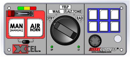
Figure 1 |
|
this incorrectly, the siren will automatically return and |
|
you will need to start again at step 4.
Latching Auxiliary Buttons to 3 Level Switch - By moving the 3 level switch to any level, you can then press any of the auxilary buttons to add to that Level of the 3 Level Switch. Example, Moving the 3 Level Switch to Level 1, then pressing the Auxiliary Button A (A will illuminate RED) will add Aux A output to Level 1. After selections are made in any level, move the 3 Level Switch to next desired location and repeat process. When all levels are programmed to the desired settings, move the 3 Level Switch back to Level 0 and press the Manual Button to move to the next step.
Auxiliary Button Type (ON/OFF, Momentary, Timed) - By pressing any of the Auxiliary Buttons, the backlighting should either be solid ON RED or Flashing RED. If the button is solid ON RED, that means the button is in the ON/OFF setting, if the button is Flashing RED, that means this button is momentary (or timed 8 Seconds for Auxilary Button F). Once all Auxiliary Buttons are programmed to the desired setting, press the Manual Button to move to the next step.
Park Kill, Horn Ring In, Light Alert, Button Press Buzzer - Auxiliary Button A programs the Park Kill feature, if the button is solid ON RED, the Park Kill is a +12V signal, if the button is flashing RED, the Park Kill input will be a Ground signal. Auxiliary Button B programs the Horn Ring In feature, if the button is solid ON RED, the Horn Ring In is a +12V signal, if the button is flashing RED, the Horn Ring In is a Ground signal. Auxiliary C programs the Light Alert feature, if the button is solid ON RED, the internal buzzer will beep every 8 seconds if any lighting switch is ON, if the button is flashing RED, Light Alert is disabled. Auxiliary Button D programs the Button Press Buzzer, if the button is solid ON RED, anytime a button is pressed, the buzzer will beep, if the button is flashing RED, this feature will be disabled. Once all the features have been programmed to the desired setting, press the Manual button to exit programming.
To change the backlighting intensity, Please follow the following instructions:
1.Move Level Switch to Level 0 (furthest to the left)
2.Turn all Auxiliary Switches off
3.Move Rotary Knob to RAD (Radio)
4.Press and hold MAN (Manual) button for at least 2 seconds (at this point the Auxiliary Button backlighting indication will turn RED) , then release.
5.Immediately press, in order, Auxiliary Buttons F - D - C - A
6.If entered correctly, the Air Horn button will be flashing and you can now adust the backlighting intensity.
Adjustable Backlighting - The Backlighting can be adjusted as desired. Pressing the Air Horn button will change the backlighting brightness. There are 4 steps; Off, 30%, 70% 100% brightness. When finished making adjustments, press the Manual Button.
Standard Features
3-Level Switch - This switch is used for changing the emergency warning mode. When the 3-Level Switch is switched to the far left position, the unit is off. When the 3-Level Switch is in the first position from the left, the level 1 configuration of the lights is turned on. When the 3-Level Switch is in the second position from the left, the level 1 & 2 configuration of lights are turned on. When the 3-Level Switch is in the third position from the left, the level 1, 2, & 3 configuration of the lights are turned on. Level 1, 2, & 3 activate the LightAlert. These default settings can be altered using the rear facing dip switches as well as entering programming mode.
WAIL Rotary Knob- This position produces the Wail tone when selected. Operation of this feature is affected by SirenLock, 3-Level Switch, Park
Kill, and Title 13 features. See these sections for details.
YELP Rotary Knob - This position produces the Yelp tone when pressed. Operation of this feature is affected by SirenLock, 3-Level Switch, Park
Kill, and Title 13 features. See these sections for details.
3
Standard FeaturesCont:
ALT TONE Rotary Knob - This position produces either Hi-Lo or Hyper-Yelp dependent on Dip Switch 12. Operation of this feature is affected by SirenLock, 3-Level Switch, Park Kill, and Title 13 features. See these sections for details.
Radio (RRB) - This position operates Radio ReBroadcast over siren speakers. These inputs are transformer coupled to prevent loading of the radio. The audio from the radio is rebroadcast over the siren speakers. The siren tones do not operate when this is activated. All other control functions operate normally. To connect in the signal to be broadcast, simply connect the two signal lines to the RRB and RRB inputs of the Amplifier (polarity is not an issue). The RRB feature will automatically shutoff to protect from overheating of the XCEL Siren.
MANUAL Push-Button - In its default configuration, this push-button generates the Manual Wail tone. When pressed, the Manual Wail tone will ramp up to the maximum tone and hold. It will hold as long as the MANUAL push-button is held. When the MANUAL push-button is released, the tone will ramp down and return to the previous function. This button can work the Hit-N-Go mode as well. Operation of this feature is affected by
SirenLock, 3-Level Switch, Park Kill, and Title 13 features. See these sections for details.
AIR HORN Push-Button - In its default configuration, the AIR HORN push-button produces the Air Horn tone as long as it is pressed. It will override all other siren tones. The AIR HORN push-button will work with Park Kill and SirenLock. Operation of this feature is affected by Title 13 features.
Auxiliary A-F Push-Buttons -As configured through the programming mode, six on/off Auxiliary push-buttons are readily accessible for controlling the Auxiliary outputs of the Amplifier. Each Auxiliary push-button can be custom labeled with the supplied label kit. Each push-button is backlighted when activated to alert the operator. The default setting is for each Auxiliary push-button to control the corresponding Auxiliary output of the Amplifier.
Auxiliary A through F supplies power to the load through the connector pins labeled A thru F.
Hands-Free - The Hands-Free mode is directly linked to Auxiliary push-button E. By default, the Hands-Free mode is disabled. When Dip Switch 3 is Up (ON), the Auxiliary Push-Button E is then configured for Hands-Free. If Auxiliary Push-Button E is active, then Hands-Free mode is active, but waiting for an initial press of the horn ring to activate the WAIL. A second press of the horn ring will activate the YELP. Pressing the horn ring a third time will activate the ALT TONE. A fourth press of the horn ring will return to the WAIL. This type of scrolling will continue until the user deactivates the Hands-Free Scroll. Pressing the Auxiliary E turns off the tone and deactivates the Hands-Free Scroll. Pressing and holding the horn ring will turn off the tone, but leave Hands-Free in the active mode.
Hands-Free Level 3 Lighting - The Hands-Free mode has the option of working directly with Level 3 lighting. If Dip Switch 2 is Up (ON), the above Hands Free feature will also turn on Level 3 lighting. To activate and de-activate this feature, follow the above instructions under Hands-Free.
Horn Ring - The XCEL Siren accepts either a positive or a ground signal into the Horn Ring input, this is defined in Programming Mode. The Horn Ring signal is disconnected from the vehicle and connected to the Horn Ring input. The Horn Relay wire is then run from the Amplifier to the horn of the vehicle. This allows the Horn Ring to execute some of the user selectable functions of the XCEL Siren. The Horn Ring can be configured to multiple functions in the Siren Active and Siren Inactive modes of operation. The Horn Ring is set to Scroll in the Hands-Free mode and cannot be changed.
Horn Ring Transfer - The Horn Ring Transfer allows the Horn Ring to be disabled from the vehicle horn and the controls transferred to control other siren tones. The Horn Ring Transfer can be set to occur at Level 2 or Level 3.
Hit-N-Go - Hit-N-Go only works when a siren tone is active and if Dip Switch 7 is Up (ON). Once a siren tone is active, Hit-N-Go is activated simply by pressing the vehicle horn ring. It will go to the Override tone for 8 seconds and then return to the primary tone. The actual tone for the Hit-N-Go depends on which position the rotary knob is in. If the WAIL is active then the Hit-N-Go (Override) tone is the Yelp tone. If the YELP is active then the Hit-N-Go tone is the Hyper-Yelp 1 tone and if the ALT TONE push-button is active then the Hit-N-Go tone is the Hyper-Lo 1 tone. The MANUAL push-button is also a Hit-N-Go activator.
Scroll - Scroll only works when a siren tone is active and Dip Switch 7 is down (OFF). Once a siren tone is active, Scroll is activated simply by pressing the vehicle horn ring. The XCEL Siren will Scroll from Wail to Yelp to Alt and then back to Wail, if Dip Switch 6 is up (ON), the XCEL Siren will Scroll from Waill to Yelp to Alt to OFF and then back to Wail. Holding the vehicle horn ring for greater than a half second will cause the XCEL Siren to generate the Air Horn.
Park Kill - By default, the Park Kill puts the siren tones in standby and drops out the Level 3B output. Park Kill occurs when the vehicle is shifted into park. The default for the polarity of the Park Kill input is +12V (Programmable to a GND). Once Park Kill is activated, the siren tones are in standby.
The siren tones will remain in standby until the vehicle is shifted into drive and an action occurs such as pressing one of the Siren push-buttons, changing the position of the 3-Level Switch, or keying the microphone. The Level 3B and siren tones are in standby during Park Kill and the Auxiliary push-buttons are not affected by the Park Kill function.
4
 Loading...