


INSTALLATION & OPERATION MANUAL
3890 SERIES
MASTERCOM SIREN
|
SIRENS AND CONTROLS |
|
|
Contents: |
|
|
Introduction .......................................................... |
2 |
|
Standard Features ............................................... |
2 |
|
Unpacking & Pre-Installation ............................... |
4 |
|
Installation & Mounting ........................................ |
5 |
|
Set-Up and Adjustment ........................................ |
8 |
|
Operation............................................................ |
11 |
|
Maintenance ...................................................... |
13 |
|
Troubleshooting ................................................. |
14 |
|
Parts List (Replacement Parts / Exploded View)16 |
|
|
Wiring Diagram .................................................. |
20 |
|
External Ignition Lead Relay ............................. |
21 |
|
Common MIC Option ......................................... |
22 |
|
Options ............................................................... |
23 |
|
Specifications ..................................................... |
23 |
|
Notes .................................................................. |
25 |
|
Warranty ............................................................. |
26 |
|
Read all instructions and warnings before installing and using. |
|
IMPORTANT: |
INSTALLER This manual must be delivered to the end user of |
this equipment. |
1

Introduction
The enhanced 3890 series siren is an improved series of electronic sirens that has been designed to meet the needs of all emergency vehicles. This series of sirens incorporates the popular packaging and features of the original Mastercom siren with microprocessor based circuitry and MOSFET technology. Most of the original Mastercom features are available along with many new added features that are not available on any other Code 3 siren such as; Park Kill, Instant "ON", Adj. Backlighting, " Scroll " Mode and more.
 !
!
WARNING!
Sirens are an integral part of an effective audio/visual emergency warning system. However, sirens are only short range secondary warning devices. The use of a siren does not insure that all drivers can or will observe or react to an emergency warning signal, particularly at long distances or when either vehicle is traveling at a high rate of speed. Sirens should only be used in a combination with effective warning lights and never relied upon as a sole warning signal. Never take the right of way for granted. It is your responsibility to be sure you can proceed safely before entering an intersection, driving against traffic, or responding at a high rate of speed.
The effectiveness of this warning device is highly dependent upon correct mounting and wiring. Read and follow the manufacturer’s instructions before installing or using this device. The vehicle operator should check the equipment daily to insure that all features of the device operate correctly.
To be effective, sirens must produce high sound levels that potentially can inflict hearing damage. Installers should be warned to wear hearing protection, clear bystanders from the area and not to operate the siren indoors during testing. Vehicle operators and occupants should assess their exposure to siren noise and determine what steps, such as consultation with professionals or use of hearing protection should be implemented to protect their hearing.
This equipment is intended for use by authorized personnel only. It is the user’s responsibility to understand and obey all laws regarding emergency warning devices. The user should check all applicable city, state and federal laws and regulations.
Code 3, Inc., assumes no liability for any loss resulting from the use of this warning device.
Proper installation is vital to the performance of the siren and the safe operation of the emergency vehicle. It is important to recognize that the operator of the emergency vehicle is under psychological and physiological stress caused by the emergency situation. The siren system should be installed in such a manner as to: A) Not reduce the acoustical performance of the system, B) Limit as much as practical the noise level in the passenger compartment of the vehicle, C) Place the controls within convenient reach of the operator so that he can operate the system without losing eye contact with the roadway.
Emergency warning devices often require high electrical voltages and/or currents. Properly protect and use caution around live electrical connections. Grounding or shorting of electrical connections can cause high current arcing, which can cause personal injury and/or severe vehicle damage, including fire.
PROPER INSTALLATION COMBINED WITH OPERATOR TRAINING IN THE PROPER USE OF EMERGENCY WARNING DEVICES IS ESSENTIAL TO INSURE THE SAFETY OF EMERGENCY PERSONNEL AND THE PUBLIC.
Standard Features
The enhanced 3890 series sirens consist of integrated controls and amplifier in a single package with 4 and 6 circuit lighting controls available as well. The models are as follows:
3892 - Primary Tones: Wail, Yelp, Hi-Lo, Air Horn
- Secondary Tones: HyperYelp, HyperLo
3892L4,L6 - Primary Tones: Wail, Yelp, Hi-Lo, Air Horn
-Secondary Tones: HyperYelp, HyperLo
-4 or 6 auxillary lighting controls
2
3894L6S same features as 3892L6 with an addation of a rear panel connector to accommodate
a single microphone system.
The following features are standard in the new style 3890 series (tones and sequences may differ by model number):
Instant-On- There is no " ON/OFF " switch. Selecting any siren function, or keying the microphone will activate the siren assuming the siren is connected directly to a nonignition switched source of +12V.
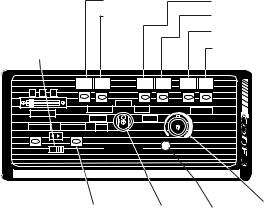
|
Switch E |
|
Switch A |
|
|
Horn Ring |
Switch F |
|
Switch B |
|
|
Select |
|
|
|
Switch C |
|
Slide Switch |
|
|
Switch D |
||
|
GUN EMG |
SGN LTD RTD |
A |
|
|
|
WAIL |
|
|
|
|
LIGHTING |
STANDBY |
YELP |
VOLUME |
|
|
|
|
|
|||
RADIO |
HI-LO |
|
|
|
|
|
|
|
|
||
MANUAL AIR HORN |
|
|
|
|
|
|
MODEL 3894L6 |
|
|
|
|
YOUR POLICE DEPT.'S NAME HERE (OPTION) |
|
|
|
||
|
Manual/Air |
Rotary |
|
Max. PA |
PA/RRB |
|
|
Volume |
|||
|
Horn |
Selector |
|
Volume |
Control |
|
Push-buttons Switch |
|
Adjust |
Switch |
|
SirenLock TM (L4 and L6 Models Only)- An interlock circuit between the siren and the light control circuits that permits
automatic siren tones only when the progressive switch is in Level 3 or in Level 2 or 3 (user selectable - works in conjunction with the horn transfer relay). This feature is used in jurisdictions that require warning lights to be on before the siren is activated.
Park Kill- This feature deactivates the siren tones when the vehicle is shifted into park. Once PKILL is activated the siren will remain deactivated until an action occurs such as moving the selector switch to STANDBY, returning lighting level switch to position one or keying the microphone. Any action will enable the siren tones to function again with the exception of the auxillary lighting pushbuttons.On lighting models this also drops-out the Level 3 lighting output for a powerdown mode when in park.
Adjustable Backlighting- Backlighting is independent of siren power. Allows connecting to dimmer if desired.
Radio Power- Allows user to power the two-way radio from the siren when the ignition is "OFF".
Automatic Short Circuit Protection- The siren will sense a short circuit on the speaker terminals and automatically go to standby until the fault is removed. Once the fault is removed the siren will return to normal operation.
Lighting Level "3 " Drop-out- When vehicle is shifted to PARK and the PKILL feature is connected, Level 3 lighting will drop-out. This is indicated by the "red" LED exstinguishing. This is a power down mode and can be defeated by setting the 4 -position rear dip switch to the PKILL "OFF" position on the lighting board.
Scroll Mode- Setting the slide switch on the rear of the siren to the SCROLL position will put siren in scroll mode. This will allow "scrolling" through tones utilizing sharp taps on the horn ring, or a switch, via the Remote siren input. In this mode holding the horn ring for prolonged durations will produce the Airhorn sound. See OPERATION section for further details.
Hit-n-Go Mode - Setting the slide switch on the rear of the siren to the Hit-N-Go position will put the siren in the Hit-n-Go mode.This mode will be most familiar to existing Mastercom users. A seven second override is standard for all tones when activated by the Manual button or the Remote input.See OPERATION section for details.
Automatic Siren Tones - Industry standard Wail, Yelp, and Hi-Lo tones.
AIR HORN Tone - Electronic AIR HORN sound.
Instant Public Address - Public Address override of all siren functions when the microphone Push-to-Talk key is pressed.
Status LED - An indicator LED, visible on the front panel that informs the operator of the status of his siren at all times.
Radio Rebroadcast - Broadcast Two-way radio reception over siren speakers. These inputs are transformer
coupled to prevent loading of the radio. |
3 |
|
Remote Siren Switching - The siren accepts either a positive or a ground (earth) signal, usually from the vehicle's horn switch (or other user supplied switch), and remotely activates the MANUAL or AIR HORN (if supplied) function. Selection is made via the front panel slide switch.The siren is factory set for a GND
(Earth) signal and may be reconfigured to accept a positive signal. See Set-up and Adjustments section for details.
Tone Priority/Manual Wail - The following tones are produced while pushing the MANUAL Push-button or triggering the user-supplied REMOTE siren switch:
Manual Wail when the MANUAL Push-button is depressed while the rotary switch is in the STANDBY position.
Yelp when the MANUAL Push-button is depressed while the rotary switch is in the WAIL position.
HyperYelp when the MANUAL Push-button is depressed and the rotary switch is in the YELP position.
HyperLo when the MANUAL Push-button is depressed and the rotary switch is in the HI-LO position.
Noise Cancelling Microphone - Wired in microphone that is easily unplugged internally for service or replacement.
Power Distribution Section - A three level progressive switch for primary warning light system control plus 4 push- on/push-off auxiliary switches that are user convertible to momentary action ('L4 models). The unit may also be purchased with 6 auxiliary switches ('L6 models).
Each auxiliary switch can be custom labeled with the supplied label kit. Each label is backlit and increases intensity when activated to alert the operator. Each position of the progressive switch has its own indicator LED.
Horn Ring Transfer - ('L models only) Built in horn transfer relay that may be activated at Levels 2 and 3 of the warning
light progressive switch. Point of activation is customer Figure 2 selectable with the rear panel DIP switch.
Unpacking & Pre-installation
After unpacking your 3890 series siren, carefully inspect the unit and associated parts for any damage that may have been caused in transit. Report any damage to the carrier immediately
 !
!
WARNING!
All devices should be mounted in accordance with the manufacturer’s instructions and securely fastened to vehicle elements of sufficient strength to withstand the forces applied to the device. Ease of operation and convenience to the operator should be the prime consideration when mounting the siren and controls. Adjust the mounting angle to allow maximum operator visibility. Do not mount the Control Head Module in a location that will obstruct the drivers view. Mount the microphone clip in a convenient location to allow the operator easy access. Devices should be mounted only in locations that conform to their SAE identification code as described in SAE Standard J1849. For example, electronics designed for interior mounting should not be placed underhood, etc.
Controls should be placed within convenient reach of the driver or if intended for two person operation, the driver and/or passenger. In some vehicles, multiple control switches and/or using methods such as "horn ring transfer" which utilizes the vehicle horn switch to toggle between siren tones may be necessary for convenient operation from two positions. Controls should be placed within convenient reach* of the driver or if intended for two person operation the driver and/or passenger. In some vehicles, multiple control switches and/or using methods such as “horn ring transfer” which utilizes the vehicle horn switch to toggle between siren tones may be necessary for convenient operation from two positions.
4

Installation & Mounting
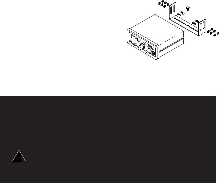
The 3890 series siren may be mounted above the dash, below the dash, on a tunnel or in a rack with the mounting bracket (bail) and the hardware supplied (see Fig. 2). Ease of operation and convenience to the operator should be the prime consideration when mounting the siren and controls.
The bail is mounted to the siren chassis by means of the "T" slot in the side of the unit and the 1/4-20 carriage bolts, washers, and nuts supplied. See Figure 2 for assembly and positioning details. Note that once the unit is installed, removal involves only loosening, not removing, the acorn nuts. Use of 1/4 - 20 HEX head bolts can damage slots and prevent easy removal of the unit.
NOTE: Set-ups and adjustments will be made in subsequent steps, depending upon the model and options purchased, that may require access to the rear area of the unit. Plan the installation and wiring accordingly.
Amplifier Connections
Siren Amplifier Connector - As a standard feature, the Siren and Auxiliary sections ('L4 & 'L6 models) of your unit come equipped with a combination plug-in terminal block/connector. To terminate the wires, strip approximately 1/4" of insulation from the end of each wire and insert it in the appropriate hole in the terminal block. Recommend using a screwdriver with a 1/8" wide blade with a 6" shaft such as an Xcelite(C) R186 or equivalent rather than a 4 1/2" adjustment screwdriver to ensure proper torque on the screws. Tighten the set-screw and proceed to the next connection.
Should you ever have to remove the unit, pull the terminal block straight out. It will unplug from the unit, leaving the wiring in place.
 !
!
WARNING!
Larger wires and tight connections will provide longer service life for components. For high current wires it is highly recommended that terminal blocks or soldered connections be used with shrink tubing to protect the connections. Do not use insulation displacement connectors (e.g. 3M® ) Scotchlock type connectors). Route wiring using grommets and sealant when passing through compartment walls. Minimize the number of splices to reduce voltage drop. High ambient temperatures (e.g. underhood) will significantly reduce the current carrying capacity of wires, fuses, and circuit breakers. Use "SXL" type wire in engine compartment. All wiring should conform to the minimum wire size and other recommendations of the manufacturer and be protected from moving parts and hot surfaces. Looms, grommets, cable ties, and similiar installation hardware should be used to anchor and protect all wiring. Fuses or circuit breakers should be located as close to the power takeoff points as possible and properly sized to protect the wiring and devices. Particular attention should be paid to the location and method of making electrical connections and splices to protect these points from corrosion and loss of conductivity. Ground (Earth)terminations should only be made to substantial chassis components, preferably directly to the vehicle battery. The user should install a circuit breaker sized to approximately 125% of the maximum Amp capacity in the supply line to protect against short circuits. For example, a 30 Amp circuit breaker should carry a maximum of 24 Amps. DO NOT USE 1/4" DIAMETER GLASS FUSES AS THEY ARE NOT SUITABLE FOR CONTINUOUS DUTY IN SIZES ABOVE 15 AMPS. Circuit breakers are very sensitive to high temperatures and will "false trip" when mounted in hot environments or operated close to their capacity.
5

 !
!
WARNING!
CONNECTION OF A 58 WATT SPEAKER TO THE SPKR TERMINAL WILL CAUSE THE SPEAKER TO BURN OUT, AND WILL VOID THE SPEAKER WARRANTY!
The sound projecting opening should be pointed forward, parallel to the ground, and not obstructed or muffled by structural components of the vehicle. Concealed or under-hood mountings in some cases will result in a dramatic reduction in performance. To minimize this reduction, mount the speaker so the sound emitted is projected directly forward and obstruction by vehicle components such as hoses, brackets, grille, etc. is minimized. Electromechanical sirens and electronic siren speakers should be mounted as far from the occupants as possible using acoustically insulated compartments and isolation mountings to minimize the transmission of sound into the vehicle. It may be helpful to mount the device on the front bumper, engine cowl or fender; heavily insulate the passenger compartment; and operate the siren only with the windows closed. Each of these approaches may cause
significant operational problems, including loss of siren performance from road slush, increased likelihood of damage to the siren in minor collisions, and the inability to hear the sirens on ot her emergency vehicles.
APPROPRIATE TRAINING OF VEHICLE OPERATORS IS RECOMMENDED TO ALERT THEM TOTHESE PROBLEMS AND MINIMIZE THE EFFECT OF THESE PROBLEMS DURING OPERATIONS.
Terminal Block Connections
10 Position Terminal Plug- ( see wiring diagram page 20 )
COM - Connect to the terminal marked "1" of one 100 W ( 11 ohm ) speaker.
SPKR - Connect to the terminal marked "2" of the 100 W ( 11 ohm ) speaker..
NOTE: An optional 200 W version is available. This will enable the user to connect two 100 W speakers in parallel. Correct phasing is important and can be accomplished by connecting both speaker terminals marked " 1 " to the COM terminal and both speaker terminals marked " 2" to the SPKR terminal.
REMOTE - Remote switch (Horn ring or foot switch). Circuit can be configured for both ground (earth) or positive signals. A horn ring transfer circuit is standard in all 3940 series "L" models. Connect to the "REMOTE" terminal on the Lighting Control Section terminal block. Unit is configured for a ground ( earth ) at the factory. See page 7 for details on configuring for a +12V input.
BLTG- Provides +12V to siren backlighting. Connect to a vehicle circuit that is powered when the ignition switch is " on ". If backlighting dimming is desired, connect to the dash lights' circuit.
CautionIf connected to the battery the backlighting will be active at all times.
PKILL- This feature automatically deactivates siren tones when the vehicle is shifted into PARK. On models with lighting control Level 3 will " drop-out " if this feature is enabled via the rear panel dip switch. Siren tones will be disabled until the vehicle is shifted out of PARK and the front panel selector switched is either returned to standby ( or another function is selected ) or the lighting level control is returned to level 1.
This circuit is activated by a negative signal. Connect this input to a circuit that is GROUNDED (Earth) when the vehicle is shifted into PARK. It is the installer's responsibility to determine an appropriate location in the vehicle circuitry to connect this wire.
RRB - Connect to one side of the two-way radio speaker.
RRB - Connect to the second side of the two-way radio speaker.
EXPWR - Connect directly to +12V terminal of the battery or a non-ignition switched source of +12V capable of supplying a minimum of 10 Amps.
6
RPWR- Provides +12V to the two-way radio with the ignition on / off . Connect the +12V power lead from the radio to this terminal. This is a 10 Amp maximum current output.
InterClear® (Optional) - Connect to the device or circuit that is to be activated by the InterClear feature.The InterClear circuit is internally current limited at 1 Amp. Should your requirements require higher currents, use the InterClear Power Booster Kit (# INTBS), available from your Code 3 supplier.
1/4" Male Quick-Connect Printed Circuit Board Terminals
+12V - Connect to a positive +12 volt DC source. It is recommended that the user protect this wire with a 10 Amp fuse(20 Amp for 200w option) or circuit breaker located at the source. Use #14 gauge wire terminated with 1/4" female, fully insulated quick-connect terminals only.
NEG - Connect to the negative terminal of the battery. This supplies ground (earth) to the siren. Use #14 gauge wire terminated with 1/4" female, fully insulated quick-connect terminals only.
Power Distribution Connections ( "L" Models)
A #8 stud is provided on the rear of the unit and is intended for use ONLY as a convenient ground (earth) " tie-point " for the light bar wiring. It is not an adequate ground (earth) for the siren or the light bar. It is recommended all ground (earth) wires attached here be terminated with a crimp-on ring terminal.
11-Position Terminal Plug - Rear Panel- (See Wiring Diagram page 20)
IMPORTANT!
Remember auxillary outputs A,B,D on L4 models and A,B,D,E,F on L6 models can supply a maximum of 20 Amps each for a combined total of 30 Amps. Install appropriate fuses in each output wire as close to the siren as possible.
SW D - Connect to the load to be controlled by Auxiliary Switch "D".
SW B - Connect to the load to be controlled by Auxiliary Switch "B".
SW C NO - Connect to the load to be controlled by the normally-open contact on Auxiliary Switch "C".
SW C NC - Connect to the load to be controlled by the normally-closed contact on Auxiliary Switch "C".
SW C COM - Common or power feed for Auxiliary Switch "C". Terminals are a SPDT circuit that may be connected as a momentary (or timed momentary with option) ignition controlled circuit, or used for switching auxiliary circuits. It will Handle 10 Amps, and should be protected with a fuse at the battery if individually fed. Can also be connected to a ground source if the load on SWC NO or SWC NC is already connected to a 12V source and needs a ground input to activate it.
SW F - ('L6 models only) Connect to the load to be controlled by Auxiliary Switch "F".
SW A - Connect to the load to be controlled by Auxiliary Switch "A".
SW E - ('L6 models only) Connect to the load to be controlled by Auxiliary Switch "E".
HORN RING - Connect to the wire coming from the vehicle horn switch at the steering wheel.
HORN - Connect to the vehicle horn or vehicle horn ring relay.
7
REMOTE - Connect to the Remote terminal on the Siren Amplifier Connector.
Lighting Models Only ( L versions )
#8 GAUGE RED WIRE PIGTAIL - provides power to the 3 Level, progressive lighting outputs only. The wire can be ordered with an optional connector to allow for convenient removal. The connector should be soldered to each wire, NOT crimped. This connection is designed to provide 50 amp service and therefore nothing smaller than #8 guage wire should be connected to it.The circuit breaker used should be sized for the actual load of the lighting used and located as close to the battery positive as possible. For quick disconnection option on 8 AWG wire see "lighting switch connector" on page 23.
4 Position Screw-type Terminal Block Connector
Important!
The total combined current for the auxillary outputs A,B,D on L4 models and A,B,D,E,F on L6 models must not exceed 30 Amps total.
+12VAUX - Connect to the positive terminal of the battery with 30 Amp circuit protection. Locate the fuse or circuit breaker at the battery and use #10 gauge wire minimum. This terminal powers switches A,B and D on L4 models and A,B,D,E and F on L6 models, and also supplied power to the siren lock & light alert circuits on both models.
LEVEL 1 - Connect to the first level of warning lights (Green LED) position "1" on level switch.
LEVEL 2 - Connect to the second level of warning lights (Yellow LED) position "2" on level switch.
LEVEL 3 - Connect to the third level of warning lights (Red LED) position "3" on level switch.
NOTE: LEVEL 1, LEVEL 2, LEVEL 3, switch progressively. Switch position 1 provides +12 volts at Level 1 terminal. Switch position 2 provides +12 volts at terminals 1 and 2. Switch position 3 provides +12 volts at terminals 1, 2, and 3.
SET-UP AND ADJUSTMENT
All of the adjustments, except MAXIMUM P.A. ADJUSTMENT, and set-up switches are
accessible from the rear of the unit. Make these adjustments and position the set-up switches prior to placing the unit inside their bail bracket (see wiring diagram, page 20).
Audio Adjustments
Radio Rebroadcast Adjustment - Place the selector switch in the RADIO position. The trimmer located on the rear panel of the siren sets the maximum level RRB will reach with the knob fully clockwise. To adjust properly, set the volume knob fully clockwise and adjust the trimmer such that normal two-way radio volume inside the vehicle produces the desired volume outside the vehicle.
Maximum P.A. Volume Adjustment - This trimmer ( located on the front panel next to the volume control knob ) sets the maximum level that the P.A. volume will reach with the front panel VOLUME control in the fully clockwise position.To adjust properly, set the front panel volume control fully clockwise and adjust the trimmer while keying the microphone until the maximum volume out of the speaker is such that there is no feedback and is intelligible. (See Figure 1)
8
 Loading...