


INSTALLATION &OPERATION MANUAL
420 BEACON
425 BEACON
420 Series Beacon
12/24v MODELS
PERMANENT AND MAGNETIC
LED AND STROBE BEACONS
Contents:
Introduction .............................................................. |
2 |
Unpacking & Pre-Installation ................................... |
2 |
Installation & Mounting ............................................ |
2 |
Magnetic Mounting .................................................. |
3 |
Permanent Mounting ............................................... |
3 |
Wiring Instructions ................................................... |
4 |
Maintenance ............................................................ |
4 |
LED Operation and Troubleshooting................... |
5-6 |
Parts List .................................................................... |
|
(Replacement Parts/Exploded View)................. |
7-11 |
D-Tech Rotator ................................................ |
12-13 |
Notes ............................................................... |
14-15 |
Warranty ................................................................ |
16 |
IMPORTANT: Read all instructions and warnings before installing and using.
INSTALLER: This manual must be delivered to the end user of this equipment.

Introduction
The 420/425 Beacon has a sleek, aerodynamtic profile and is a powerful mid-sized, magnetically or permanently mounted warning device.
The use of this or any warning device does not insure that all drivers can or will observe or react to an emergency warning signal. Never take the right-of-way for granted. It is your responsibility to be sure you can proceed safely before entering an intersection, driving
!against traffic, responding at a high rate of speed, or walking on or around traffic lanes. The effectiveness of this warning device is highly dependent upon correct mounting and
WARNING! wiring. Read and follow the manufacturer’s instructions before installing or using this device. The vehicle operator should insure daily that all features of the device operate
correctly. In use, the vehicle operator should insure the projection of the warning signal is not blocked by vehicle components (i.e.: open trunks or compartment doors), people, vehicles, or other obstructions.
This equipment is intended for use by authorized personnel only. It is the user’s responsibility to understand and obey all laws regarding emergency warning devices. The user should check all applicable city, state and federal laws and regulations.
Code 3, Inc., assumes no liability for any loss resulting from the use of this warning device. Proper installation is vital to the performance of this warning device and the safe operation of the emergency vehicle. It is important to recognize that the operator of the emergency vehicle is under psychological and physiological stress caused by the emergency situation. The warning device should be installed in such a manner as to: A) Not reduce the output performance of the system, B) Place the controls within convenient reach of the operator so that he can operate the system without losing eye contact with the roadway.
Strobe power supplys and flash tubes utilize high electrical voltages and/or currents. Properly protect and use caution around live electrical connections. Grounding or shorting of electrical connections can cause high current arcing, which can cause personal injury and/or severe vehicle damage, including fire. Incandescent lamps are extremely hot,allow to cool completely before attempting to remove.
Any electronic device may create or be affected by electromagnetic interference. After installation of any electronic device operate all equipment simultaneously to insure that operation is free of interference. Never power emergency warning equipment from the same circuit or share the same grounding circuit with radio communication equipment.
PROPER INSTALLATION COMBINED WITH OPERATOR TRAINING IN THE PROPER USE OF EMERGENCY WARNING DEVICES IS ESSENTIAL TO INSURE THE SAFETY OF EMERGENCY PERSONNEL AND THE PUBLIC.
Unpacking & Pre-installation
Carefully remove the beacon and place it on a flat surface, taking care not to scratch the lens. Examine the unit for transit damage, broken lamps, etc.
If it is convenient, you may wish to test the unit before installation. To test, touch the black wire to the negative ground (earth) and the red wire to the +12 Volts D.C. A battery may be used for this purpose. If the vehicle has an electrical system other than 12 Volts D.C. negative ground (earth), and you have not ordered a specially wired beacon, contact your local representative or call the factory for instructions.
Installation & Mounting
The 420/425 Beacon may be mounted magnetically or permanently on the roof of the vehicle, or other mounting surface.
GENERAL
All devices should be mounted in accordance with the manufacturer's instructions and securely fastened to vehicle elements of sufficient strength to withstand the forces applied to the device. Driver and/or passenger air bags (SRS) will affect the way equipment should be mounted. This device should be mounted by permanent installation and within the zones specified by the vehicle manufacturer, if any. Any device mounted in the deployment area of an air bag will damage or reduce the effectiveness of the air bag and may damage or dislodge the device. Installer must be sure that this device, its mounting hardware and electrical supply wiring does not interfere with the air bag or the SRS wiring or sensors. Front or rear grille/bumper placement must avoid interference with SRS sensors. Mounting the unit inside the vehicle by a method other than permanent installation is not recommended as unit may become dislodged during swerving, sudden braking or collision.
2

Magnetic Mounting
1) Rust Stains: The magnetic mount is not intended as a permanent mounting for the beacon. Long duration usage of any magnet will expose the high iron content of the steel
!causing rust. The device should be removed when not used to prevent rust stains. Metallic debris collected by the magnet will also contribute to rust stains. Insure that the magnet is
WARNING! kept clean.
2)Surface rust stains can usually be removed with chrome polish, available at most auto part stores.
3)As with any magnetically-mounted warning device, its use on the exterior of a moving vehicle is at the sole discretion and responsibility of the user.
This magnetic mount product provides a secure, temporary installation in most circumstances and is recommended for stationary use only. For maximum warning signal, mount the beacon on the highest possible flat, level surface of the vehicle.
The 420/425 Magnetic Based Beacon provides a secure, temporary installation in most circumstances. The beacon should be placed in the center of the roof where the least amount of curvature occurs. The beacon should not be used on a vinyl covered roof. Before installing, check all four magnets for clinging debris. Any foreign matter can reduce holding power and scratch your vehicle's paint. The roof surface should be dry and have a dull, not glossy finish. A glossy, highly waxed finish will reduce the friction; and the magnets, though quite powerful, will have a greatly reduced effect. Place and remove your beacon without sliding to avoid scratching. When removing, lift one edge then the other, straight up without sliding.
When the beacon is placed on the roof, it should adhere firmly to the surface. If the unit slides or moves easily, a proper installation has not been obtained, most probably for one of the reasons mentioned above. In this situation, the user should not attempt to drive with the beacon in place. If the user has attempted to obtain a good installation and still has questions, we recommend that the user (customer) contact one's distributor or the factory.
Permanent Mounting
The 420/425 Permanent Mount Beacon provides a secure, permanent installation. To begin installation, remove the lens, position the Beacon Base in the desired location, and mark the centers of the (4) mounting holes on vehicle roof or mounting surface, using the Beacon Base as a template. Measure out and mark half the distance between the mounting hole marks to locate the exact center of the mounting hole pattern for the cable hole. Drill a 1/2" hole at the center of the pattern for the cable and drill (4) 7/32" holes through at the (4) mounting hole centers (NOTE: DO NOT USE THE BEACON BASE AS A DRILL GUIDE OR DRILL THROUGH BEACON BASE). Remove any burrs from around all of the holes. Apply a liberal amount of customer supplied RTV sealant around the cable hole and the (4) mounting holes to seal out moisture (NOTE: BE SURE TO APPLY ENOUGH RTV SEALANT TO FILL THE GAPS BETWEEN THE BEACON BASE AND THE VEHICLE ROOF CURVATURE). Carefully feed the cable through the 1/2" hole and Place base in proper position making sure all 4 screw holes line up with base mounting holes. Run (4) 3/16" x 1" machine screws with lock washers, obtained locally, up through the drilled holes (For thicker surfaces or larger curved surfaces use longer screws). Make sure all 4 screws are pointing up. Place one nut onto each screw and make sure that the nuts have seated themselves into the matching hex shaped pockets in the base. Tighten screws until base is properly secured to mounting surface. Once the base is secure, replace lens and tighten the two end screws.
|
! |
Utilizing non-factory specified screws and/or mounting brackets and/or the |
WARNING! |
improper number of screws may result in failure of the mounting system and |
|
|
|
severe damage to the vehicle as well as loss of warranty coverage on the |
|
|
equipment. |
3

Wiring Instructions
!
WARNING!
Larger wires and tight connections will provide longer service life for components. For high current wires it is highly recommended that terminal blocks or soldered connections be used with shrink tubing to protect the connections. Do not use insulation displacement connectors (e.g. 3M® Scotchlock type connectors). Route wiring using grommets and sealant when passing through compartment walls. Minimize the number of splices to reduce voltage drop. High ambient temperatures (e.g. under-hood) will significantly reduce the current carrying capacity of wires, fuses, and circuit breakers. Use "SXL" type wire in engine compartment. All wiring should conform to the minimum wire size and other recommendations of the manufacturer and be protected from moving parts and hot surfaces. Looms, grommets, cable ties, and similar installation hardware should be used to anchor and protect all wiring.
Particular attention should be paid to the location and method of making electrical connections and splices to protect these points from corrosion and loss of conductivity. Ground terminations should only be made to substantial chassis components, preferably directly to the vehicle battery.
The user should install a fuse sized to approximately 125% of the maximum Amp capacity in the supply line and each switched circuit to protect against short circuits. For example, a 30 Amp fuse should carry a maximum of 24 Amps. DO NOT USE 1/4" DIAMETER GLASS FUSES AS THEY ARE NOT SUITABLE FOR CONTINUOUS DUTY IN SIZES ABOVE 15 AMPS. Circuit breakers are very sensitive to high temperatures and will "false trip" when mounted in hot environments or operated close to their capacity. Fuses or circuit breakers should be located as close to the power takeoff points as possible and properly sized to protect the wiring and devices.
420 Magnetic Mount Beacon - The 420 Beacon can be equipped with a cord that plugs into a 12/24 Volt D.C. cigarette lighter; rotate and push with reasonable moderate force which insures the best possible connection.
420 Permanent Mount Beacon - The 420 beacon is designed to operate on a 12 Volt D.C. negative ground (earth) system or alternatively 24 Volt system when specified. Use #14 GA. or larger wires. Connect black lead to vehicle chassis (earth), or preferably the negative (earth) terminal of the battery. Bring the red lead to the user supplied control switch, and then to the battery or to the stud on the battery side of the starter solenoid or alternator. Install a fuse or circuit breaker of 10 Amp capacity in the supply line to protect the vehicle's wiring system against short circuits.
420 Strobe Beacon - The 420 Strobe Beacon is designed to operate from 10-30 Volts DC. Connect the red/ black leads similarly to the 420 Permanent Mount Beacon, use a 10 Amp fuse. Blue and green wires on power supply are not used.
425 LED Beacon - The 425 LED Beacon is available as a magnetic or permanent mount unit and is designed to operate on a 12Volt DC negative ground (earth) system. Connect the leads similar to the 420 Permanent Mount Beacon and use a 7.5A fuse.
Maintenance
Do not oil or grease this unit. It is constructed with permanently lubricated bearings and plastic gears which do not need lubrication. Keep the unit clean by disassembling it and cleaning bearing surfaces with mineral spirits (turpentine), and clear any debris out of the drive gears. Clean lens and base with mild soap and water, or CODE 3® lens polish using a soft cloth.Use no SOLVENTS on lens.
!
WARNING!
Lamps are extremely hot! Allow to cool completely before attempting to remove. Gloves and eye protection should be worn when handling halogen lamps as they are pressurized and accidental breakage can result in flying glass. High voltages and or temperatures are present inside of strobe units. Disconnect from power and wait 10 minutes prior to servicing
FAILURE TO FOLLOW ABOVE WARNINGS OR INSTALLATION AND USER INSTRUCTIONS CAN RESULT IN LOSS OF WARRANTY COVERAGE.
4
WARNING! ! |
This Product contains high intensity LED devices. To prevent eye damage, |
DO NOT stare into light beam at close range. |
LED X
TM
CORNER LED MODULE
Operating Specifications for Corner LED module:
Operating Voltage: 10-16 VDC, Reverse Polarity Protection
Current Draw : Red/Amber - .5A avg @ 12.8 Volts
Blue - .8A avg @ 12.8 Volts
Available Colors - Red, Blue, and Amber
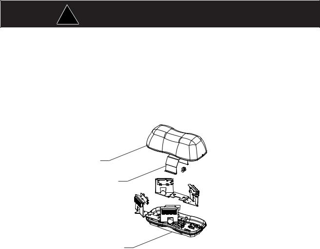
425 BEACON COVER LENS
(1)
WIRE GUARD SHROUD
(1)
LED 425 BASE (1)
Figure 1
Master/ Slave Operation
Each 360 degree corner module consists of a "master" and a "slave" driver circuit board, 360 degree optics
and LED light engines along with a dual integrated heatsink bracket.
The "master" circuit board must always be powered for the "slave" to flash. The flash pattern for each corner pair can be selected by moving jumpers J1 and J2 on the "master" to the appropriate position on the circuit board. The module is set-up for "Cycleflash" as a standard. The following chart describes the pattern for each jumper position;
360 Degree Module Flash Pattern - Table 1
Place jumpers as shown to select flash pattern: See Figure 2, page 6, for jumper installation.
Jumper Position |
Flash Pattern |
Description |
|
J1 |
J2 |
|
|
Bottom (on) |
Bottom (on) |
N/A |
|
Bottom (on) |
Top (off) |
N/A |
|
Top (off) |
Bottom (on) |
Quad Flash |
Four Pulses per flash @ 60 fpm min |
Top (off) |
Top (off) |
Cycle-Flash |
Cycles through various patterns @ 70 fpm avg. |
Both heads will be in the mode selected
5
 Loading...