


INSTALLATION & OPERATION MANUAL
3900 AND 3930 SERIES SIREN
3900 MODEL SERIES SIRENS
WITH & WITHOUT PUBLIC ADDRESS & RADIO RE-BROADCAST
NOTE: References to Public Address (PA) and Radio Re-Broadcast (RRB) features, |
|
adjustments & replacement parts, do not apply to all models. |
|
Contents: |
|
Introduction .......................................................... |
2 |
Standard Features ............................................... |
2 |
Unpacking & Pre-Installation ............................... |
3 |
Installation & Mounting ........................................ |
3 |
Set-Up and Adjustment ....................................... |
6 |
Operation ............................................................. |
7 |
Options ................................................................. |
8 |
Specifications ....................................................... |
8 |
Maintenance ........................................................ |
9 |
Troubleshooting ................................................. |
10 |
Parts List ............................................................ |
12 |
Exploded View ................................................... |
14 |
Warranty ............................................................. |
16 |
IMPORTANT: INSTALLER: This manual must be delivered to the end user of this equipment. |
|
Read all instructions and warnings before installing and using. |
|
1

Introduction
The 3930 series siren is a new series of electronic sirens that has been designed to meet the needs of all emergency vehicles. This series of sirens incorporates a rugged extruded aluminum package along with microprocessor based circuitry and MOSFET technology. Advanced features such as Park Kill, Instant "ON", Adjustable Backlighting, "Horn Ring Scroll" and more, make the 3930 series sirens extremely versatile.
 !
!
WARNING!
Sirens are an integral part of an effective audio/visual emergency warning system. However, sirens are only short range secondary warning devices. The use of a siren does not insure that all drivers can or will observe or react to an emergency warning signal, particularly at long distances or when either vehicle is traveling at a high rate of speed. Sirens should only be used in a combination with effective warning lights and never relied upon as a sole warning signal. Never take the right of way for granted. It is your responsibility to be sure you can proceed safely before entering an intersection, driving against traffic, or responding at a high rate of speed.
The effectiveness of this warning device is highly dependent upon correct mounting and wiring. Read and follow the manufacturer’s instructions before installing or using this device. The vehicle operator should check the equipment daily to insure that all features of the device operate correctly.
To be effective, sirens must produce high sound levels that potentially can inflict hearing damage. Installers should be warned to wear hearing protection, clear bystanders from the area and not to operate the siren indoors during testing. Vehicle operators and occupants should assess their exposure to siren noise and determine what steps, such as consultation with professionals or use of hearing protection should be implemented to protect their hearing.
This equipment is intended for use by authorized personnel only. It is the user’s responsibility to understand and obey all laws regarding emergency warning devices. The user should check all applicable city, state and federal laws and regulations.
Public Safety Equipment, Inc., assumes no liability for any loss resulting from the use of this warning device.
Proper installation is vital to the performance of the siren and the safe operation of the emergency vehicle. It is important to recognize that the operator of the emergency vehicle is under psychological and physiological stress caused by the emergency situation. The siren system should be installed in such a manner as to: A) Not reduce the acoustical performance of the system, B) Limit as much as practical the noise level in the passenger compartment of the vehicle, C) Place the controls within convenient reach of the operator so that he can operate the system without losing eye contact with the roadway.
Emergency warning devices often require high electrical voltages and/or currents. Properly protect and use caution around live electrical connections. Grounding or shorting of electrical connections can cause high current arcing, which can cause personal injury and/or severe vehicle damage, including fire.
PROPER INSTALLATION COMBINED WITH OPERATOR TRAINING IN THE PROPER USE OF EMERGENCY WARNING DEVICES IS ESSENTIAL TO INSURE THE SAFETY OF EMERGENCY PERSONNEL AND THE PUBLIC.
Standard Features
The 3930 series sirens consist of integrated controls and amplifier in a single package. The siren is available in two models as follows:
The following features are standard on Model 3930 sirens:
Siren Tones - Industry standard Wail, Yelp, and HyperYelp tones.
AIR HORN Tone - Electronic AIR HORN sound.
2

Instant-On- There is no " ON/OFF " switch. Selecting any siren function, or keying the microphone will activate the siren assuming the siren is connected to a source of +12V.
Automatic Short Circuit Protection- The siren will sense a short circuit on the speaker terminals and automatically go to standby until the fault is removed. Once the fault is removed the siren will return to normal operation.
Instant Public Address - Public Address override of all siren functions when the microphone Push-to-Talk (PTT) key is pressed.
Noise Cancelling Microphone - Wired in microphone that is easily unplugged internally for service or replacement.
In addition to the standard features of the Model 3930 siren listed above, the following features are standard on Model 3932 sirens:
Radio Rebroadcast - Broadcasts Two-way radio reception over siren speakers. These inputs are transformer coupled to prevent loading of the radio.
Park Kill- This feature deactivates the siren tones when the vehicle is shifted into park. Once PKILL is activated the siren will remain deactivated until the vehicle is shifted into gear and the siren is restarted using the Horn Ring Scroll feature or the front panel switches.
Adjustable Backlighting- Backlighting is independent of siren power. Allows connecting to dimmer if desired.
Horn Ring (Remote) Scroll - The siren accepts either a positive or a ground (Earth) signal, usually from the vehicle's horn switch (or other user supplied switch), and remotely scrolls through the siren tones or activates AIR HORN function. See Set-up and Adjustments section for details.
InterClear® - This unique feature can be used to activate additional warning lights for 7 seconds, each time the siren mode is changed using either the control switches or the vehicle horn ring, thus allowing an additional level of warning in situations such as intersections without the operator having to take his hands off the wheel or his eyes off the road.
Unpacking & Pre-installation
After unpacking your 3930 series siren, carefully inspect the unit and associated parts for any damage that may have been caused in transit. Report any damage to the carrier immediately.
Installation & Mounting
The 3930 series siren may be mounted above the dash, below the dash, on a tunnel or in a rack with the mounting bracket (bail) and the hardware supplied (see Fig. 1). Ease of operation and convenience to the operator should be the prime consideration when mounting the siren and controls.
 !
!
WARNING!
All devices should be mounted in accordance with the manufacturer’s instructions and securely fastened to vehicle elements of sufficient strength to withstand the forces applied to the device. Ease of operation and convenience to the operator should be the prime consideration when mounting the siren and controls. Adjust the mounting angle to allow maximum operator visibility. Do not mount the Control Head Module in a location that will obstruct the drivers view. Mount the microphone clip in a convenient location to allow the operator easy access. Devices should be mounted only in locations that conform to their SAE identification code as described in SAE Standard J1849. For example, electronics designed for interior mounting should not be placed underhood, etc.
Controls should be placed within convenient reach* of the driver or if intended for two person operation the driver and/or passenger. In some vehicles, multiple control switches and/or using methods such as “horn ring transfer” which utilizes the vehicle horn switch to toggle between siren tones may be necessary for convenient operation from two positions.
*Convenient reach is defined as the ability of the operator of the siren systems to manipulate the controls from his normal driving/riding position without excessive movement away from the seat back or loss of eye contact with the roadway.
3
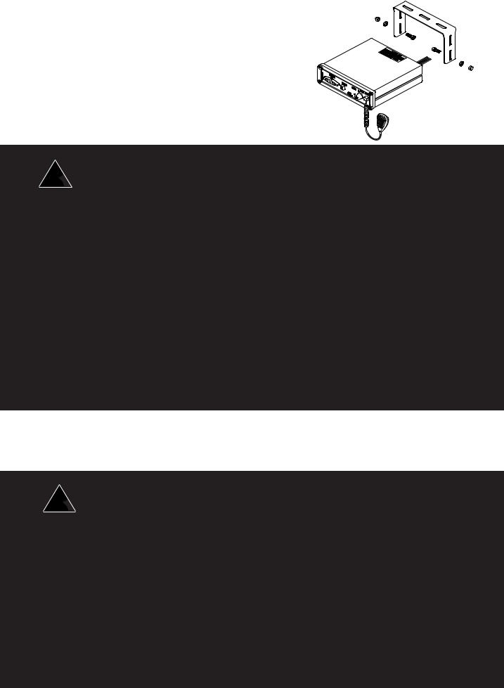
The bail is mounted to the siren chassis by means of the "T" slot in the side of the unit and the 1/4-20 hex head bolts, washers, and nuts supplied. See Figure 1 for assembly and positioning details. Note that once the unit is installed, removal involves only loosening, not removing, the acorn nuts.
NOTE: Set-ups and adjustments will be made in subsequent steps,
depending upon the model and options purchased, that may
require access to the rear area of the unit. Plan the installation and Figure 1 wiring accordingly.
 !
!
WARNING!
Larger wires and tight connections will provide longer service life for components. For high current wires it is highly recommended that terminal blocks or soldered connections be used with shrink tubing to protect the connections. Do not use insulation displacement connectors (e.g. 3M® ) Scotchlock type connectors). Route wiring using grommets and sealant when passing through compartment walls. Minimize the number of splices to reduce voltage drop. High ambient temperatures (e.g. underhood) will significantly reduce the current carrying capacity of wires, fuses, and circuit breakers. Use "SXL" type wire in engine compartment. All wiring should conform to the minimum wire size and other recommendations of the manufacturer and be protected from moving parts and hot surfaces. Looms, grommets, cable ties, and similar installation hardware should be used to anchor and protect all wiring.
Fuses or circuit breakers should be located as close to the power takeoff points as possible and properly sized to protect the wiring and devices. Particular attention should be paid to the location and method of making electrical connections and splices to protect these points from corrosion and loss of conductivity. Ground (Earth) terminations should only be made to substantial chassis components, preferably directly to the vehicle battery.
The user should install a circuit breaker sized to approximately 125% of the maximum Amp capacity in the supply line to protect against short circuits. For example, a 30 Amp circuit breaker should carry a maximum of 24 Amps.
DO NOT USE 1/4" DIAMETER GLASS FUSES AS THEY ARE NOT SUITABLE FOR CONTINUOUS DUTY IN SIZES ABOVE 15 AMPS. Circuit breakers are very sensitive to high temperatures and will "false trip" when mounted in hot environments or operated close to their capacity.
Connections (see Figure 2)
ORANGE - Speaker - Connect to 100W ( 11 ohm ) speaker leads.
 !
!
WARNING!
CONNECTION OF A 58 WATT SPEAKER TO THE SPKR TERMINAL WILL CAUSE THE SPEAKER TO BURN OUT, AND WILL VOID THE SPEAKER WARRANTY!
The sound projecting opening should be pointed forward, parallel to the ground, and not obstructed or muffled by structural components of the vehicle. Concealed or under-hood mountings in some cases will result in a dramatic reduction in performance. To minimize this reduction, mount the speaker so the sound emitted is projected directly forward and obstruction by vehicle components such as hoses, brackets, grille, etc. is minimized. Electromechanical sirens and electronic siren speakers should be mounted as far from the occupants as possible using acoustically insulated compartments and isolation mountings to minimize the transmission of sound into the vehicle. It may be helpful to mount the device on the front bumper, engine cowl or fender; heavily insulate the passenger compartment; and operate the siren only with the windows closed.
Each of these approaches may cause significant operational problems, including loss of siren performance from road slush, increased likelihood of damage to the siren in minor collisions, and the inability to hear the sirens on other emergency vehicles.
APPROPRIATE TRAINING OF VEHICLE OPERATORS IS RECOMMENDED TO ALERT THEM TO THESE PROBLEMS AND MINIMIZE THE EFFECT OF THESE PROBLEMS DURING OPERATIONS.
4

Figure 2 - Wiring Diagram
YELLOW - REMOTE - Remote switch (Horn ring or foot switch). Circuit can be configured for both ground (earth) or positive signals. Unit is configured at the factory to operate from a ground (earth) signal. See page 6 for details on configuring for a +12V input.
WHITE - BACKLIGHTING - Provides +12V to siren backlighting. Connect to a vehicle circuit that is powered when the ignition switch is " on ". If backlighting dimming is desired, connect to the dash lights' circuit. CautionIf connected to the battery the backlighting will be active at all times.
GRAY - PARK KILL- This feature automatically deactivates siren tones when the vehicle is shifted into PARK. Siren tones will be disabled until the vehicle is shifted out of PARK. This circuit is activated by a negative signal. Connect this input to a circuit that is GROUNDED (Earth) when the vehicle is shifted into PARK. It is the installer's responsibility to determine an appropriate location in the vehicle circuitry to connect this wire.
BLUE - RRB - Connects to the two-way radio speaker.
GREEN - InterClear® (Optional) - Connect to the device or circuit that is to be activated by the InterClear feature. The InterClear circuit is internally current limited at 1 Amp. Should your requirements require higher currents, use the InterClear Power Booster Kit (# INTBS), available from your Code 3 supplier.
Model 3932 has 1/4" Male Quick-Connect Printed Circuit Board Terminals power connections. Use #14 gauge wire terminated with1/4" female, fully insulated quick-connect terminals only.
RED - (+12V) - Connect (14 guage wire) to a positive +12 volt DC source. It is recommended that the user protect this wire with a 10 Amp fuse or circuit breaker located at the source.
BLACK - NEG - Connect (14 guage wire) to the negative terminal of the battery. This supplies ground (earth) to the siren.
5
 Loading...