


 Loading...
Encore™ MS-702
Two-Channel Main Station Instruction Manual
Document Reference
Encore MS-702 Two-Channel Main Station Instruction Manual
Part Number: 810342Z Rev. 4
Legal Disclaimers
Copyright © 2013 HME Clear-Com Ltd.
All rights reserved.
Clear-Com, the Clear-Com logo and Encore are registered trademarks or trademarks of HM Electronics, Inc.
The software described in this document is furnished under a license agreement and may be used only in accordance with the terms of the agreement.
The product described in this document is distributed under licenses restricting its use, copying, distribution, and decompilation/reverse engineering. No part of this document may be reproduced in any form by any means without prior written authorization of Clear-Com, an HME Company.
Clear-Com Offices are located in California, USA; Cambridge, UK; Montreal, Canada; and Beijing, China. Specific addresses and contact information can be found on Clear-Com’s corporate website:
www.clearcom.com
Clear-Com Contacts
Americas and Asia-Pacific Headquarters
California, United States
Tel: +1.510.337.6600
Email: CustomerServicesUS@Clearcom.com
Europe, Middle East, and Africa Headquarters
Cambridge, United Kingdom
Tel: +44 1223 815000
Email: SalesSupportEMEA@Clearcom.com
Canada Office
Quebec, Canada
Tel: +1 (450) 653-9669
China Office
Beijing Representative Office
Beijing, P.R.China
Tel: (008610)-8528-8748

CONTENTS
IMPORTANT SAFETY INSTRUCTIONS
OPERATION . . . . . . . . . . . . . . . . . . . . . . . . . . . . . . . . . . 1-1
Introduction . . . . . . . . . . . . . . . . . . . . . . . . . . . . . . . . . . . . . . . . . . . . . . . . . 1-1
Description . . . . . . . . . . . . . . . . . . . . . . . . . . . . . . . . . . . . . . . . . . . . . . . . . . 1-1
Operation . . . . . . . . . . . . . . . . . . . . . . . . . . . . . . . . . . . . . . . . . . . . . . . . . . . 1-2
Front Panel . . . . . . . . . . . . . . . . . . . . . . . . . . . . . . . . . . . . . . . . . . . . . . . . 1-2
Rear Panel . . . . . . . . . . . . . . . . . . . . . . . . . . . . . . . . . . . . . . . . . . . . . . . . 1-7
Re-Setting Program Interrupt Options . . . . . . . . . . . . . . . . . . . . . . . . . . 1-10
INSTALLATION . . . . . . . . . . . . . . . . . . . . . . . . . . . . . . . 2-1
MAINTENANCE . . . . . . . . . . . . . . . . . . . . . . . . . . . . . . . 3-1
Introduction . . . . . . . . . . . . . . . . . . . . . . . . . . . . . . . . . . . . . . . . . . . . . . . . . 3-1
MS-702 Block Diagram . . . . . . . . . . . . . . . . . . . . . . . . . . . . . . . . . . . . . . . . 3-1
Troubleshooting Tips . . . . . . . . . . . . . . . . . . . . . . . . . . . . . . . . . . . . . . . . . . 3-2
Parts List. . . . . . . . . . . . . . . . . . . . . . . . . . . . . . . . . . . . . . . . . . . . . . . . . . . . 3-4
SPECIFICATIONS . . . . . . . . . . . . . . . . . . . . . . . . . . . . . . 4-1
LIMITED WARRANTY. . . . . . . . . . . . . . . . . . . . . . . . . . 5-1
Warranty Period . . . . . . . . . . . . . . . . . . . . . . . . . . . . . . . . . . . . . . . . . . . . . . 5-1
Technical Support. . . . . . . . . . . . . . . . . . . . . . . . . . . . . . . . . . . . . . . . . . . . . 5-1
Warranty Repairs and Returns . . . . . . . . . . . . . . . . . . . . . . . . . . . . . . . . . . . 5-2
Non-Warranty Repairs and Returns . . . . . . . . . . . . . . . . . . . . . . . . . . . . . . . 5-2
Extended Warranty. . . . . . . . . . . . . . . . . . . . . . . . . . . . . . . . . . . . . . . . . . . . 5-2
Service Contract . . . . . . . . . . . . . . . . . . . . . . . . . . . . . . . . . . . . . . . . . . . . . . 5-3
Liability . . . . . . . . . . . . . . . . . . . . . . . . . . . . . . . . . . . . . . . . . . . . . . . . . . . . 5-3
Clear-Com® |
i |
MS-702 Two-Channel Main Station Instruction Manual |
|

i i
T w o - C h a n n e l M a i n S t a t i o n

Please read and follow these instructions before operating this product.
IMPORTANT SAFETY INSTRUCTIONS
1.Read these instructions.
2.Keep these instructions.
3.Heed all warnings.
4.Follow all instructions.
5.Do not use this apparatus near water.
6.Clean only with dry cloth.
7.Do not block any ventilation openings. Install in accordance with the manufacturer’s instructions.
8.Do not install near any heat sources such as a radiators, heat registers, stoves, or other apparatus (including amplifiers) that produces heat.
9.Do not defeat the safety purpose of the polarized or grounding-type plug. A polarized plug has two blades, with one blade wider than the other. A grounding-type plug has two blades and a third grounding prong. The wide blade or the third prong are provided for your safety. If the provided plug does not fit into your outlet, consult an electrician for replacement of the obsolete outlet.
10.Protect the power cord from being walked on or pinched particularly at plugs, convenience receptacles, and the point where they exit from the apparatus.
11.Only use attachments/accessories specified by the manufacturer.
12.Use only with the cart, stand, tripod, bracket, or table specified by the manufacturer, or sold with the apparatus. When a cart is used, use caution when moving the cart/apparatus combination to avoid injury from tip-over.
13.Unplug this apparatus during lightning storms or when unused for long periods of time.
14.Refer all servicing to qualified service personnel. Servicing is required when the apparatus has been damaged in any way, such as power-supply cord or plug is damaged, liquid has been spilled or objects have fallen into the apparatus, the apparatus has been exposed to rain or moisture, does not operate normally, or has been dropped.
15.WARNING: To reduce the risk of fire or electric shock, do not expose this product to rain or moisture.
Please familiarize yourself with the safety symbols in Figure 1. When you see these symbols on this product, they warn you of the potential danger of electric shock if the unit is used improperly. They also refer you to important operating and maintenance instructions in the manual.
i i |
C l e a r - C o m ® |
|
M S - 7 0 2 T w o - C h a n n e l M a i n S t a t i o n I n s t r u c t i o n M a n u a l |
CAUTION
RISK OF ELECTRIC SHOCK
DO NOT OPEN
This symbol alerts you to the presence of uninsulated dangerous voltage within the product's enclosure that might be of sufficient magnitude to constitute a risk of electric shock. Do not open the product's case.
This symbol informs you that important operating and maintenance instructions are included in the literature accompanying this product.
Figure 1: Safety Symbols
EMC AND SAFETY
The MS-702 meets all relevant CE, FCC, UL, and CSA specifications set out below:
EN55103-1 Electromagnetic compatibility. Product family standard for audio, video, audio-visual, and entertainment lighting control apparatus for professional use. Part 1: Emissions.
EN55103-2 Electromagnetic compatibility. Product family standard for audio, video, audio-visual, and entertainment lighting control apparatus for professional use. Part 2: Immunity.
UL 60065-7, CAN/CSA-C22.2 No.60065-3, IEC 60065-7 Safety requirements.
And thereby compliance with the requirement of Electromagnetic Compatibility Directive 2004/108/EC and Low Voltage Directive 2006/95/EC
This device complies with Part 15 of the FCC Rules. Operation is subject to the following two conditions: (1) this device may not cause harmful interference, and (2) this device must accept any interference received, including interference that may cause undesired operation.
C l e a r - C o m ® |
i i i |
M S - 7 0 2 T w o - C h a n n e l M a i n S t a t i o n I n s t r u c t i o n M a n u a l |
|

OPERATION
The MS-702 two-channel main station is a powerful, yet user-friendly unit that can serve as the heart of a Clear-Com system.
INTRODUCTION
Congratulations on choosing this Clear-Com product. Clear-Com was established in 1968 and remains the market leader in providing intercoms for entertainment, broadcast and industrial applications. The ruggedness and high build-quality of Clear-Com products defines the industry standard. In fact, many of our original beltpacks and main stations are still in daily use around the world.
The MS-702 two-channel main station is a powerful, yet user-friendly unit that can serve as the heart of a Clear-Com system. We recommend that you read through this manual completely to better understand the functions of the MS-702. If you encounter a situation or have a question that this manual does not address, contact your dealer or call Clear-Com directly at the factory. Our applications support and service people are standing by to assist you. (Refer to Chapter 5: “Warranty” for contact information.) Thank you for selecting Clear-Com for your communications needs.
DESCRIPTION
The Clear-Com MS-702 is a two-channel, one-rack space main station ideal for ENG and EFP trucks, production studio consoles, theatre, live performances, and small TV facilities. It features excellent speech intelligibility in all noise levels and can be tailored to your needs through its programmable options.
Selectable two-channel talking and/or listening allows the operator to communicate on either of the intercom channels separately or on both at once. The illuminated dual-action talk buttons provide electronic momentary or latching capability. Monitoring can be done through the headset, the integral speaker, or both at once. The MS-702 offers both visual and audible call signaling to attract the attention of operators who have removed their headsets or turned off their speakers. The remote mic kill (RMK) feature provides the ability to turn off all open mics on remote beltpacks.
The MS-702 can control a paging speaker for studio announcements. A front panel button activates both this function and an associated relay. A balanced program input allows monitoring of external audio using the headset or speaker.
This main station accepts dynamic headsets. Individual sidetone controls for each intercom channel allow the operator to vary the level of his/her own voice as heard in the headset and speaker. It also accepts Clear-Com gooseneck panel microphones.
The integral speaker can be turned on or off by a convenient front panel switch. An automatic speaker dipping circuit will lower the level of the
1 - 1 |
C l e a r - C o m ® |
|
M S - 7 0 2 T w o - C h a n n e l M a i n S t a t i o n I n s t r u c t i o n M a n u a l |

speaker when the announce button, talk buttons or program interrupt are activated. This feature helps minimize feedback.
The MS-702 also incorporates a dual-channel program interrupt system (IFB). When activated, one or more stations can interrupt the program audio to either another intercom station or a talent wearing Clear-Com’s wired or wireless talent receivers. Clear-Com’s stand-alone IFB system can also be connected to this station.
The MS-702 provides 30-volt DC power to operate Clear-Com beltpacks and remote stations. This power is distributed between the two channels, and will support up to 60 headset stations or 20 speaker stations. Clear-Com’s fail-safe design automatically shuts down the power to a channel when a short circuit or electronic overload is sensed on that channel. The other channel will continue to operate normally. Once the fault condition is removed, the MS-702’s fail-safe circuit will restore power, even under full load conditions. LED indicators signal a short or overload on either channel.
The DC power output details are:
•1.2A continuous output
•2A peak output (not exceeding the 1.2A rating for more than 2 seconds per 30 second period)
•1.75A max on any channel, with electronic current limiter (not exceeding the 1.2A rating for more than 2 seconds per 30 second period)
The MS-702 will operate from any AC line voltage between 90 and 240 volts AC at 50 or 60 Hz. The MS-702 installs in a standard 19-inch (48.26 cm) equipment rack, using only one rack space. The steel chassis and extra-thick front panel with integral rack ears maintains legendary Clear-Com ruggedness. Three 3-pin XLR connectors are provided for connection to each intercom channel.
The MS-702 is compatible with all Clear-Com party-line intercoms.
OPERATION
Normal operation of the MS-702 main station requires access only to the front panel controls. The controls located elsewhere on the unit are intended to be set-and-forget in nature. For intercom operation, set the listen-level controls for each channel to the desired level and press the talk buttons when talking. If a headset is used, set the sidetone control for each channel for the desired amount of sidetone in the earphone. If using the panel mic and speaker, set the sidetone controls for minimum feed-through to the speaker to prevent feedback.
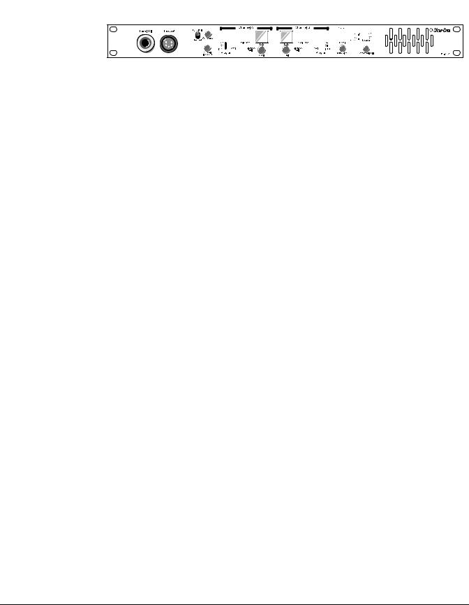
FRONT PANEL
The controls, indicators, and connectors found on the MS-702 front panel are shown in the following figure and are described the text that follows. The numbers in the left column refer to Figure 1.
C l e a r - C o m ® |
2 - 2 |
M S - 7 0 2 T w o - C h a n n e l M a i n S t a t i o n I n s t r u c t i o n M a n u a l |
|
18 |
19 |
12 |
14 |
5 |
1 |
5 |
8 |
26 |
10 |
9 |
7 |
8 |
6 |
2 |
6 |
7 |
3 |
11 |
Figure 1: Front Panel
1.Talk Buttons: Each channel has an illuminated talk button for activating the microphone feed to that channel. Each talk button has a dual action (momentary or latching feature) depending on how the button is pressed. If desired, the latching function for each channel can be defeated using the option switches on the rear panel. The following describes the various functions of these multi-purpose buttons:
•MOMENTARY: Press and hold the talk button while you are speaking. Release it when you are finished.
•LATCHING: Press the talk button quickly to latch the talk function. Press the button again to turn off the talk function.
•TALK INDICATION: The talk button will illuminate yellow whenever the talk function is activated. The talk button illuminates blue whenever the station is receiving power, but the talk function is off.
•CALL INDICATION: The call button will flash red when a call signal is received on that channel.
•CALL ON TALK: Each channel can optionally be set to send a call signal whenever you press the talk button. This function activates program interrupts or any other call-activated function available on other stations. Option switches on the rear panel enable this function.
•SPEAKER MUTE: If the front panel speaker is turned on, pressing either talk button will reduce the speaker output level to avoid feedback.
The talk buttons can be labeled to indicate their function. To label the talk buttons, use the following procedure:
1.Pull the talk button straight off.
2.Insert a small flat blade screwdriver into the slot between the cap and the body of the button and gently twist. This will remove the cap.
3.Remove the square white diffuser from the cap.
4.Insert a 1/2 in. (1.27 cm) x 1/2 in. (1.27 cm) square of thin paper with the needed description into the cap. Follow it up with the square white diffuser and press the cap onto the body of the button. Press the button back into the front panel.
2.Call Buttons: Each channel has its own call button. Pressing a call button will send a call signal on that channel. All the call lights on that channel will flash. Call signals can also be sent while talking if required. The call
1 - 3 |
C l e a r - C o m ® |
|
M S - 7 0 2 T w o - C h a n n e l M a i n S t a t i o n I n s t r u c t i o n M a n u a l |

button will flash while the call button is pressed, indicating the presence of a call signal on the line.
3.Tone Alert: An audible tone alert can be enabled to sound when a call signal is received on either channel. This can be useful when the operator's attention has been drawn away from the MS-702 indicator panel. Press the tone alert button to alternately enable or disable the audible tone alert. The button illuminates blue when the audible tone alert is enabled. When enabled, the tone alert will sound when a call button on a beltpack or station is pressed. The tone alert will not sound if a call signal is originated at the MS-702 station. The level can be adjusted by the control on the rear panel (See number 4 on the rear panel diagram later in this chapter).
5.Listen Level Controls: Each channel has a separate listen level control. Turn these controls to set the listen level you need on each channel. Turn the control completely counterclockwise to silence a channel.
6.Sidetone Controls: Each channel has a sidetone null control. Sidetone is the level of your own voice that you hear while talking on the intercom. Setting a comfortable level of sidetone will ensure that the intercom line sounds alive and also helps you modulate your voice relative to other voices on the line.
Typically, different sidetone null settings are needed depending upon whether you are using the gooseneck panel microphone along with the speaker. Use one of the following procedures to correctly set the sidetone level controls.
Sidetone Adjustment Procedure for Gooseneck Microphone with Speaker turned on:
1.Turn off the party-line link (A+B) switch.
2.Turn the level control for channel B all the way down. Set the level control for channel A to a comfortable level.
3.Press the channel A talk button and speak into the microphone while turning the sidetone null control for channel A slowly back and forth. There should be a point where your voice (and any accompanying acoustic feedback) disappears. This is the null point.
4.Repeat this procedure for channel B by turning the channel A level control down and adjusting the channel B controls.
Sidetone Adjustment Procedure for Headset:
1.Turn off the party-line link (A+B) switch.
2.Turn the level control for channel B all the way down. Set the level control for channel A to a comfortable level by having someone talk to you from another station.
3.Press the channel A talk button and speak into the microphone while turning the sidetone null control for channel A slowly back and forth until you hear your voice at a comfortable level in the headset.
4.Repeat this procedure for channel B by turning the channel A level control down and adjusting the channel B controls.
C l e a r - C o m ® |
2 - 4 |
M S - 7 0 2 T w o - C h a n n e l M a i n S t a t i o n I n s t r u c t i o n M a n u a l |
|
Loading...