


 Loading...
Partyline User Guide
V.1.2
PN: 810588Z Rev: A 04/12/12

Document Reference
Clear-Com HelixNet Partyline User Guide
Part Number: 810588Z Revision: A
Legal Disclaimers
Copyright © 2012 HME Clear-Com Ltd.
All rights reserved.
Clear-Com, the Clear-Com logo, and Clear-Com Concert are trademarks or registered trademarks of HM Electronics, Inc.
The software described in this document is furnished under a license agreement and may be used only in accordance with the terms of the agreement.
The product described in this document is distributed under licenses restricting its use, copying, distribution, and decompilation/reverse engineering. No part of this document may be reproduced in any form by any means without prior written authorization of Clear-Com, an HME Company.
Clear-Com Offices are located in California, USA; Cambridge, UK; Montreal, Canada; and Beijing, China. Specific addresses and contact information can be found on Clear-Com’s corporate website:
www.clearcom.com
Clear-Com Contacts
Americas and Asia-Pacific Headquarters
California, United States
Tel: +1.510.337.6600
Email: CustomerServicesUS@clearcom.com
Europe, Middle East, and Africa Headquarters
Cambridge, United Kingdom
Tel: +44 1223 815000
Email: SalesSupportEMEA@clearcom.com
Canada Office
Quebec , Canada
Tel: +1 (450) 653-9669
China Office
Beijing Representative Office
Beijing, P.R.China
Tel: +8610 65811360 / 65815577
2HelixNet Partyline User Guide

Contents
1 |
Introduction........................................................................................................ |
8 |
|
|
1.1 |
Audience ................................................................................................................................. |
8 |
|
1.2 |
Important Safety instructions................................................................................................... |
9 |
|
1.2.1 |
Safety symbols .............................................................................................................. |
10 |
|
1.3 |
Further information................................................................................................................ |
10 |
2 |
User Interfaces................................................................................................. |
11 |
|
|
2.1 |
HMS-4X Main Station: Front panel ....................................................................................... |
11 |
|
2.1.1 |
HMS-4X Main Station front panel: Channel keyset....................................................... |
14 |
|
2.2 |
HMS-4X Main Station: Rear panel........................................................................................ |
15 |
|
2.2.1 |
HMS-4X Main Station rear panel: Interface modules.................................................... |
17 |
|
2.3 |
HBP-2X Beltpack .................................................................................................................. |
18 |
|
2.3.1 |
HBP-2X user controls (front and side view) .................................................................. |
18 |
|
2.3.2 |
HBP-2X connectors and controls (rear view)................................................................ |
20 |
|
2.3.3 |
HBP-2X beltclip, beltloops and feet (base view) ........................................................... |
21 |
3 |
Installing HelixNet Partyline............................................................................ |
22 |
|
|
3.1 |
Planning your HelixNet Partyline installation ........................................................................ |
23 |
|
3.1.1 |
Comparing digital with analog cabling .......................................................................... |
23 |
|
3.1.2 |
Topologies (layouts)...................................................................................................... |
25 |
|
3.2 |
Installing HelixNet Partyline .................................................................................................. |
28 |
|
3.2.1 |
Environmental information ............................................................................................ |
28 |
|
3.2.2 |
Installing the HMS-4X Main Station .............................................................................. |
28 |
|
3.2.3 |
Installing the HBP-2X Beltpacks ................................................................................... |
29 |
4 Configuring and Managing the HMS-4X Main Station .................................. |
31 |
||
|
4.1 |
Using the Menus ................................................................................................................... |
31 |
|
4.1.1 |
Configuring settings ...................................................................................................... |
31 |
|
4.1.2 |
Exiting Menu mode........................................................................................................ |
32 |
|
4.2 |
Configuring the Audio settings .............................................................................................. |
32 |
|
4.2.1 |
Audio settings for the headset....................................................................................... |
32 |
|
4.2.2 |
Audio settings for the Program Input............................................................................. |
34 |
|
4.2.3 |
Audio settings for Program IFB [Interruptible Foldback] ............................................... |
34 |
|
4.2.4 |
Audio settings for the SA [Stage Announce] Output ..................................................... |
35 |
|
4.2.5 |
Audio settings for the Hot Mic Output ........................................................................... |
35 |
3HelixNet Partyline User Guide

4.2.6 |
Audio settings for the front panel (gooseneck) mic....................................................... |
36 |
4.3 |
Setting Station Settings......................................................................................................... |
36 |
4.3.1 |
Setting key latching ....................................................................................................... |
36 |
4.3.2 |
Setting the RMK (Remote Mic Kill) key......................................................................... |
37 |
4.3.3 |
Setting display screen brightness ................................................................................. |
38 |
4.3.4 |
Setting key brightness................................................................................................... |
38 |
4.3.5 |
Setting the screensaver ................................................................................................ |
39 |
4.4 |
Configuring the channel settings........................................................................................... |
39 |
4.4.1 |
Editing the channel label ............................................................................................... |
39 |
4.4.2 |
Assigning the Program Listen to a channel .................................................................. |
40 |
4.5 |
Configuring the Control I/O ................................................................................................... |
41 |
4.5.1 |
Configuring Opto inputs ................................................................................................ |
41 |
4.5.2 |
Configuring Relay outputs............................................................................................. |
42 |
4.6 |
Configuring Module Settings................................................................................................. |
42 |
4.6.1 |
Configuring a Four-wire interface module ..................................................................... |
43 |
4.6.2 |
Configuring a Two-wire interface module ..................................................................... |
46 |
4.6.3 |
Configuring the Module Settings: Version information.................................................. |
49 |
4.7 |
Administration........................................................................................................................ |
50 |
4.7.1 |
Viewing the network details (IP address)...................................................................... |
50 |
4.7.2 |
Viewing the current versions of the software ................................................................ |
51 |
4.7.3 |
Updating the software ................................................................................................... |
51 |
4.7.4 |
Locking and unlocking the HBP-2X beltpack menus .................................................... |
52 |
4.7.5 |
Resetting the main station to default (factory mode) settings....................................... |
53 |
4.8 |
Diagnostics............................................................................................................................ |
53 |
4.8.1 |
Viewing hardware information....................................................................................... |
53 |
4.8.2 |
Viewing temperature information .................................................................................. |
54 |
4.8.3 |
Viewing powerline information and status..................................................................... |
55 |
4.8.4 |
Misc [Miscellaneous] ..................................................................................................... |
55 |
5 Configuring and Managing the HBP-2X Beltpack ......................................... |
56 |
|
5.1 |
Using the Menus ................................................................................................................... |
56 |
5.1.1 |
Configuring settings ...................................................................................................... |
56 |
5.1.2 |
Exiting Menu mode........................................................................................................ |
57 |
5.2 |
Configuring the Audio settings .............................................................................................. |
57 |
5.3 |
Configuring the Beltpack Settings......................................................................................... |
59 |
5.3.1 |
Assigning channels ....................................................................................................... |
59 |
5.3.2 |
Setting Talk key latching ............................................................................................... |
60 |
5.3.3 |
Setting the beltpack to vibrate when called................................................................... |
60 |
5.4 |
Configuring the Display Settings........................................................................................... |
61 |
4HelixNet Partyline User Guide

5.4.1 |
Setting display screen brightness ................................................................................. |
61 |
5.4.2 |
Setting the brightness of the Talk, Call and Menu keys................................................ |
61 |
5.4.3 |
Setting the screensaver ................................................................................................ |
62 |
5.5 |
Administration........................................................................................................................ |
63 |
5.5.1 |
Viewing the IP address ................................................................................................. |
63 |
5.5.2 |
Viewing the current version of the software .................................................................. |
63 |
5.5.3 |
Updating the beltpack software..................................................................................... |
64 |
5.5.4 |
Resetting the beltpack to default (factory mode) settings............................................. |
65 |
5.6 |
Diagnostics............................................................................................................................ |
65 |
5.6.1 |
Viewing the hardware (main PCB) on the beltpack ...................................................... |
65 |
5.6.2 |
Viewing powerline information and status..................................................................... |
65 |
5.6.3 |
General.......................................................................................................................... |
66 |
6 Using the HMS-4X Main Station...................................................................... |
67 |
|
6.1 |
Using the gooseneck mic, loudspeaker and headset ........................................................... |
67 |
6.1.1 |
Switching between the headset mic and the gooseneck mic ....................................... |
69 |
6.2 |
Entering and exiting Menu mode .......................................................................................... |
69 |
6.3 |
Using the channel keysets .................................................................................................... |
70 |
6.4 |
Using the All Talk key............................................................................................................ |
71 |
6.5 |
Using the SA [Stage Announce] key..................................................................................... |
72 |
6.6 |
Using the RMK [Remote Mic Kill ] key .................................................................................. |
72 |
6.7 |
Line 1 and 2 LEDs................................................................................................................. |
72 |
7 Using the HBP-2X Beltpack ............................................................................ |
73 |
|
7.1 |
Using the beltpack keysets ................................................................................................... |
73 |
7.2 |
Entering and exiting Menu mode .......................................................................................... |
74 |
7.3 |
Adjusting the Program Feed volume level. ........................................................................... |
74 |
8 Connecting to Other Intercom Systems ........................................................ |
75 |
|
8.1 |
Connecting HelixNet Partyline to Encore.............................................................................. |
75 |
8.1.1 |
About Encore................................................................................................................. |
75 |
8.1.2 |
Quick reference: Connecting to Encore ........................................................................ |
76 |
8.1.3 |
Connecting to an Encore main station .......................................................................... |
77 |
8.1.4 |
Connecting to Encore remote stations.......................................................................... |
78 |
8.2 |
Connecting HelixNet Partyline to RTS (Telex) 2W (two-wire) systems ............................... |
79 |
8.2.1 |
About RTS TW (two-wire) systems............................................................................... |
79 |
8.2.2 |
Quick reference: Two-wire connection to RTS 2W system .......................................... |
80 |
8.2.3 |
Connecting to an RTS (Telex) intercom station ............................................................ |
81 |
8.3 |
Connecting HelixNet Partyline to Tempest ........................................................................... |
83 |
8.3.1 |
About Tempest.............................................................................................................. |
83 |
8.3.2 |
Quick reference: Two-wire connection to Tempest....................................................... |
84 |
5HelixNet Partyline User Guide

8.3.3 |
|
Two-wire connection to Tempest .................................................................................. |
85 |
8.3.4 |
|
Quick reference: Four-wire connection to Tempest...................................................... |
87 |
8.3.5 |
|
Four-wire connection with Tempest.............................................................................. |
88 |
8.4 |
Connecting HelixNet Partyline to CellCom / FreeSpeak....................................................... |
89 |
|
8.4.1 |
|
About CellCom / FreeSpeak ......................................................................................... |
89 |
8.4.2 |
|
Quick reference: Two-wire connection to CellCom / FreeSpeak .................................. |
90 |
8.4.3 |
|
Two-wire connection to CellCom / FreeSpeak.............................................................. |
91 |
8.4.4 |
|
Quick reference: Four-wire connection to CellCom / FreeSpeak ................................. |
93 |
8.4.5 |
|
Four-wire connection to CellCom / FreeSpeak ............................................................. |
94 |
8.5 |
Connecting HelixNet Partyline to the DX210 ........................................................................ |
95 |
|
8.5.1 |
|
About the DX210........................................................................................................... |
95 |
8.5.2 |
|
Quick reference: Two-wire connection to DX210.......................................................... |
96 |
8.5.3 |
|
Two-wire connection to the DX210 ............................................................................... |
97 |
8.5.4 |
|
Quick reference: Four-wire connection to DX210 ......................................................... |
99 |
8.5.5 |
|
Four-wire connection to the DX210............................................................................. |
100 |
8.6 |
Connecting HelixNet Party-line to Eclipse .......................................................................... |
101 |
|
8.6.1 |
|
About Eclipse .............................................................................................................. |
101 |
8.6.2 |
|
Quick reference: Two-wire connection to Eclipse....................................................... |
102 |
8.6.3 |
|
Two-wire connection to an Eclipse Median system frame.......................................... |
103 |
8.6.4 |
|
Quick reference: Four-wire connection to Eclipse ...................................................... |
105 |
8.6.5 |
|
Four-wire connection to Eclipse .................................................................................. |
106 |
9 Specifications ................................................................................................ |
107 |
||
9.1 |
Main Station (HMS-4X) ....................................................................................................... |
107 |
|
9.1.1 |
|
Connectors .................................................................................................................. |
107 |
9.1.2 |
|
Microphone pre-amplifier ............................................................................................ |
107 |
9.1.3 |
|
Headphone amplifier ................................................................................................... |
108 |
9.1.4 |
|
Loudspeaker amplifier................................................................................................. |
108 |
9.1.5 |
|
Program line input and Four-wire option module inputs ............................................. |
109 |
9.1.6 |
|
Four-wire module outputs ........................................................................................... |
109 |
9.1.7 |
|
Stage Announce outputs............................................................................................. |
109 |
9.1.8 |
|
Hot Mic output ............................................................................................................. |
110 |
9.1.9 |
|
Partyline ...................................................................................................................... |
110 |
9.1.10 |
Ethernet....................................................................................................................... |
111 |
|
9.1.11 |
Mains power ................................................................................................................ |
111 |
|
9.1.12 |
Environmental ............................................................................................................. |
111 |
|
9.1.13 |
Dimensions and weight ............................................................................................... |
111 |
|
9.2 |
Two-wire module: general................................................................................................... |
112 |
|
9.2.1 |
|
Connectors .................................................................................................................. |
112 |
6HelixNet Partyline User Guide

9.2.2 |
Dimensions and weight ............................................................................................... |
112 |
|
9.2.3 |
Power requirements .................................................................................................... |
112 |
|
9.2.4 |
Environmental ............................................................................................................. |
112 |
|
9.3 |
Four-wire module: general .................................................................................................. |
113 |
|
9.3.1 |
Connectors .................................................................................................................. |
113 |
|
9.3.2 |
Dimensions and weight ............................................................................................... |
113 |
|
9.3.3 |
Environmental ............................................................................................................. |
113 |
|
9.4 |
Beltpack (HBP-2X) .............................................................................................................. |
113 |
|
9.4.1 |
Connectors .................................................................................................................. |
113 |
|
9.4.2 |
Microphone pre-amplifier ............................................................................................ |
114 |
|
9.4.3 |
Headphone amplifier ................................................................................................... |
115 |
|
9.4.4 |
Dimensions and weight ............................................................................................... |
115 |
|
9.4.5 |
Power requirements .................................................................................................... |
115 |
|
9.4.6 |
Environmental ............................................................................................................. |
116 |
|
Appendix A: |
Compliance................................................................................. |
117 |
|
Appendix B: |
Menu maps ................................................................................. |
119 |
|
Appendix C: |
Cabling reference....................................................................... |
127 |
|
Appendix D: |
Troubleshooting......................................................................... |
129 |
|
7HelixNet Partyline User Guide

1 Introduction
This guide is intended to help you install, configure, and use the HelixNet Partyline™ system.
HelixNet Partyline is a digital intercom system, featuring the award-winning I.V Core Technology from Clear-Com®. The system is designed to be as simple to use and configure as a two-wire intercom / analog Partyline system, while exploiting the flexibility and network management capabilities of a matrix system.
To expedite integration with your existing intercom infrastructure, HelixNet Partyline also features:
•Highly configurable Control I/O and Module settings.
•Flexible cabling options (microphone cable, fiber, CAT5).
•Optional Two-wire and Four-wire interface modules.
1.1Audience
Chapters / appendices |
|
Target audience (roles) |
|
2 |
User Interfaces |
|
Technicians and technical managers who have been |
3 |
Installing HelixNet Partyline |
|
tasked with: |
|
|
||
9 |
Specifications |
|
• Installing HelixNet Partyline. |
|
|
||
Appendix A:Compliance |
|
• Integrating HelixNet Partyline with other intercom systems. |
|
|
|
||
Appendix C:Cabling reference |
|
|
|
2 |
User Interfaces |
|
System administrators who have been tasked with configuring and |
4 |
Configuring and Managing |
|
administrating HelixNet Partyline. |
|
|
||
|
the HMS-4X Main Station |
|
|
5 |
Configuring and Managing |
|
|
|
the HBP-2X Beltpack |
|
|
9 |
Specifications |
|
|
Appendix B: Menu maps |
|
|
|
2 |
User Interfaces |
|
Users (operators) of the HelixNet main station and beltpacks. |
6 |
Using the HMS-4X |
|
|
|
Main Station |
|
|
7 |
Using the HBP-2X Beltpack |
|
|
|
|
Table |
1: Audience |
8 HelixNet Partyline User Guide

1.2Important Safety instructions
1.Read these instructions.
2.Keep these instructions.
3.Heed all warnings.
4.Follow all instructions.
5.Do not use this apparatus near water.
6.Clean only with dry cloth.
7.Do not block any ventilation openings. Install in accordance with the manufacturer’s instructions.
8.Do not install near any heat sources such as radiators, heat registers, stoves, or other apparatus (including amplifiers) that produce heat.
9.Do not defeat the safety purpose of the polarized or grounding-type plug. A polarized plug has two blades and a third grounding prong. The wide blade or the third prong are provided for your safety. If the provided plug does not fit into your outlet, consult an electrician for replacement of the obsolete outlet.
10.Protect the power cord from being walked on or pinched particularly at plugs, convenience receptacles, and the point where they exit from the apparatus.
11.Only use attachments/accessories specified by the manufacturer.
12.Use only with the cart, stand, tripod, bracket, or table specified by the manufacturer, or sold with the apparatus. When a cart is used, use caution when moving the cart/apparatus combination to avoid injury from tip-over.
13.Unplug this apparatus during lightning storms or when unused for long periods of time.
14.Refer all servicing to qualified service personnel. Servicing is required when the apparatus has been damaged in any way, such as power-cord supply or plug is damaged, liquid has been spilled or objects have fallen into the apparatus, the apparatus has been exposed to rain or moisture, does not operate normally, or has been dropped.
15.Warning: To reduce the risk of fire or electric shock, do not expose this product to rain or moisture.
9HelixNet Partyline User Guide

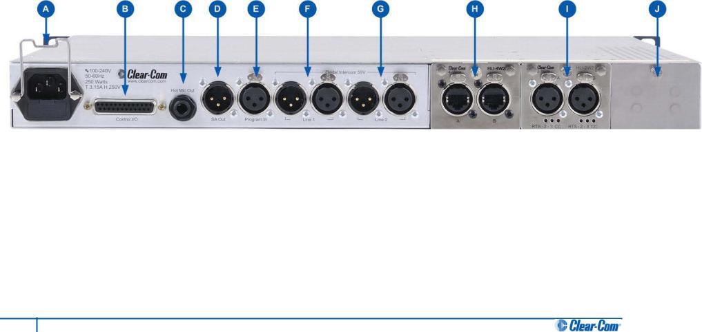
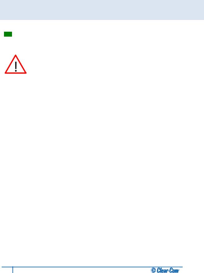
1.2.1 Safety symbols
Familiarize yourself with the safety symbols in Figure 1: Safety symbols. These symbols are displayed on the apparatus and warn you of the potential danger of electric shock if the system is used improperly.
Figure 1: Safety symbols
Important note:
For compliance notices, see Appendix A: Compliance.
1.3 Further information
For the latest information about HelixNet Partyline, including software updates, see: http://www.clearcom.com/product/helixnet.
For information about Clear-Com accessories, including headsets [  ] and gooseneck mics [
  ], see http://www.clearcom.com/product/accessories.
For legal and contact information, see Page 2 of this guide.
10 HelixNet Partyline User Guide
2 User Interfaces
2.1 HMS-4X Main Station: Front panel
Figure 2: HMS-4X Main Station: Front panel
11 HelixNet Partyline User Guide
Key to HMS-4X Main Station: Front panel
Feature Description
AEar for rack mounting Main Station.
BHeadset socket (4-pin XLR–M)
CGooseneck microphone socket (3-pin female Tuchel connector)
DMic control [ MIC ON]. Press to activate mic audio.
EHeadset key [ HSET]. Press to activate the headset mic and deactivate the gooseneck mic (if connected). Audio output to the loudspeaker is diverted to the headphones.
F |
Menu. Press to display the main station menus in the display screens [ G ]. Use the |
|
rotary control [ H ] for each display screen to scroll and select menu items. |
|
|
GChannel keyset. There is a keyset (set of controls) dedicated to each of the four available channels. See 2.1.1 HMS-4X Main Station front panel: Channel keyset.
HStage Announce [SA]. Press to talk to connected Public Address (PA) / Stage Announce (SA) system (see 2.2 HMS-4X Main Station: Rear panel).
When the SA is pressed, Mic select [MIC ON] is also lit bright red, indicating that mic audio is active.
ILEDs for lines 1 and 2 (partylines). When an LED is lit:
•Green, the line is functioning.
•Amber, the line is busy.
•Red, there is an error / issue with the line.
J |
Loudspeaker. When a headset is connected [ B ] and selected [ E ], loudspeaker |
|
output is diverted to the headphones. |
|
- |
12 HelixNet Partyline User Guide

KProgram feed audio level rotary control [Program].
To increase the volume of the program feed to the loudspeaker / headphones, turn clockwise (up to 360°).
To decrease the volume, turn anticlockwise (up to 360°). As you increase or decrease the volume, the level control LEDs pass through a range of indicator colors:
LED color |
Volume level |
|
Green |
Low |
|
Amber / Green |
Low / Medium |
|
Amber |
Medium |
|
Red / Amber |
Medium / High |
|
Red |
High |
|
|
Table 2: Volume Indicator colors |
|
|
|
|
LLoudspeaker / Headphone audio level rotary control [Main]. To increase the volume to the loudspeaker / headphones, turn clockwise (up to 360°). To decrease the volume, turn anticlockwise (up to 360°).
As you increase or decrease the volume, the level control LEDs pass through a range of indicator colors. For more information, see Table 2: Volume Indicator colors above
[K ].
MRemote Mic Kill [RMK]. Press to:
•Send a message to all connected HelixNet HBP-2X beltpacks to deselect any latched keyset Talk routes.
•Turn off any latched Talk routes on connected analog partyline beltpacks.
NAll Talk. Press to talk to all channels (intercom devices and systems) connected to the main station.
OUSB 2.0 (Micro-AB) connector. For software upgrades (see 4.7.3 Updating the software).
PUSB 2.0 (Standard-A) connector. For software upgrades (see 4.7.3 Updating the software).
Table 3: Key to HMS-4X Main Station front panel diagram
Important note:
The HMS-4X Main Station does not have a power switch, button or key. The system powers up when you connect the power supply. Power up takes 15-20 seconds (depending on the number of beltpacks connected).
13 HelixNet Partyline User Guide
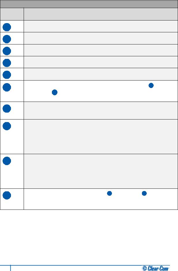
2.1.1 HMS-4X Main Station front panel: Channel keyset
Figure 3: HMX-4 Main Station (Front panel): Keyset
Key to HMS-4X Main Station front panel: Channel keyset
Feature Description
ADisplay screen. The following default information is displayed onscreen:
•The channel label [  ].
].
•The channel listen (volume) level [  ].
].
•The number of people listening and talking [  ] on the channel.
In Menu mode, the display screens display the four levels of menu. The menu hierarchy proceeds left to right:
•The top level menu is presented in the first screen (furthest left on the front panel).
•The lowest level menu is presented in the fourth screen (furthest right on the front panel).
Note:
If the display is in Menu mode, the display screen times out of Menu mode and displays the channel label if no key is pressed for 20 seconds.
For more information about Menu mode, see 4.1 Using the Menus.
BTalk key. Press to talk to all channels.
CCall key. Press to send a call signal to all nodes (intercom devices and systems) listening into the channel.
DRotary control. Turn to increase or decrease the volume level for the channel, or to scroll menu items when in menu mode. To select menu items, press (push) the control.
Table 4: Key to HMS-4x Main Station front panel: Key Set
Note:
If the HMS-4X Main Station remains inactive for 10 minutes, the display screens enter screensaver mode (see 4.3.5 Setting the screensaver).
14 HelixNet Partyline User Guide
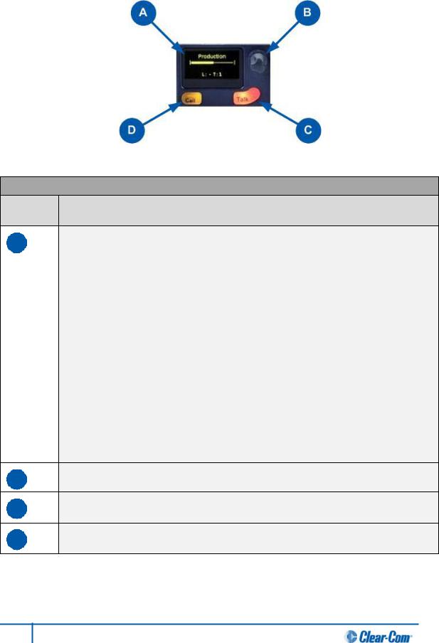
2.2 HMS-4X Main Station: Rear panel
Figure 4: HMS-4X Main Station: Rear panel
15 HelixNet Partyline User Guide
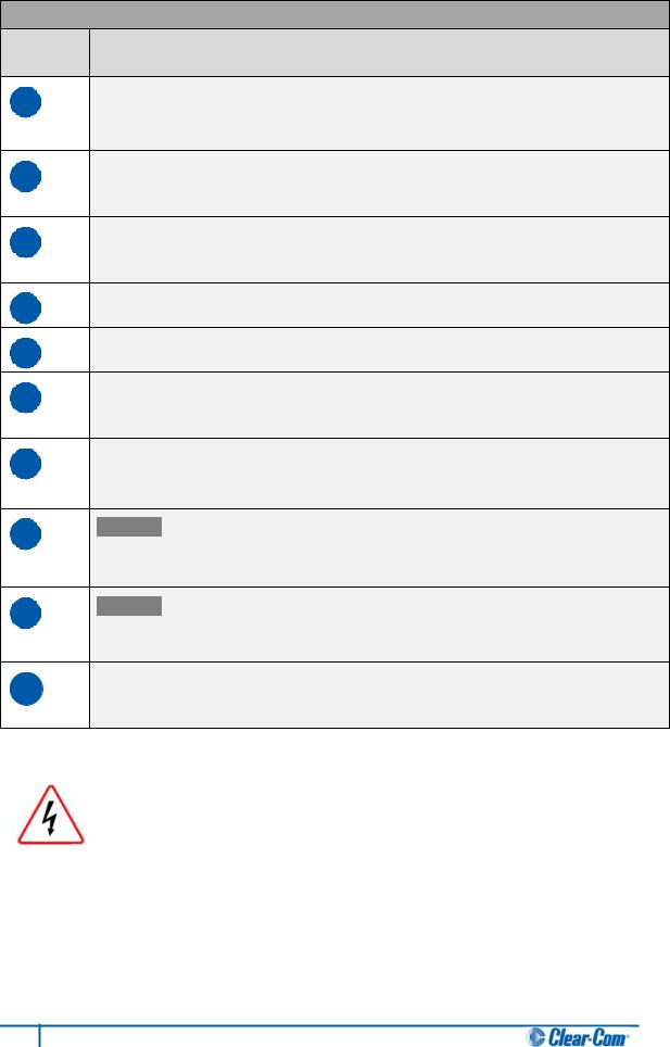
Key to HMS-4X Main Station: Rear panel
Feature Description
APower supply with metal cable restrainer. The power supply operates at 100 - 240 VAC / 50-60Hz / 250 watts / T 3.15A H 250 V.
BControl I/O (25 way female D-type). Use to connect up to 4 relay control outputs or 4 optically isolated control inputs (see 4.5 Configuring the Control I/O).
CHot Mic output. The Hot Mic output is always live. Audio from the mic is routed through the Hot Mic output even if the mic is inactive (off).
DSA [Stage Announce] line out (3-pin male XLR).
EProgram Input (3-pin female XLR).
FLine 1 (partyline). (3-pin male and female XLR connectors). Up to 10 beltpacks can be connected to a line, depending on the cable type and distance from the main station.
GLine 2 (partyline). (3-pin male and female XLR connectors). Up to 10 beltpacks can be connected to a line, depending on the cable type and distance from the main station.
HOptional: Four-wire interface module (Ethercon type RJ45 connectors). For more information, see Table 8: HMS-4X Main Station rear panel: Interface Modules.
IOptional: Two-wire interface module (3-pin female XLR connectors). For more information, see Table 8: HMS-4X Main Station rear panel: Interface Modules.
JSpare interface module bay. You can fit up to three optional interface modules to the HelixNet main station. For more information, see Table 8: HMS-4X Main Station rear panel: Interface Modules.
Table 5: Key to HMS-4X Main Station rear panel diagram
Only connect power supply to earthed supply sockets. Ensure that the power supply is routed to avoid sharp bends, hot surfaces, pinches and abrasion.
For more safety guidance, see the Safety Instructions at the front of this guide.
Important note:
The HMS-4X Main Station does not have a power switch, button or key. The system powers up when you connect the power supply. Power up takes 15-20 seconds.
16 HelixNet Partyline User Guide
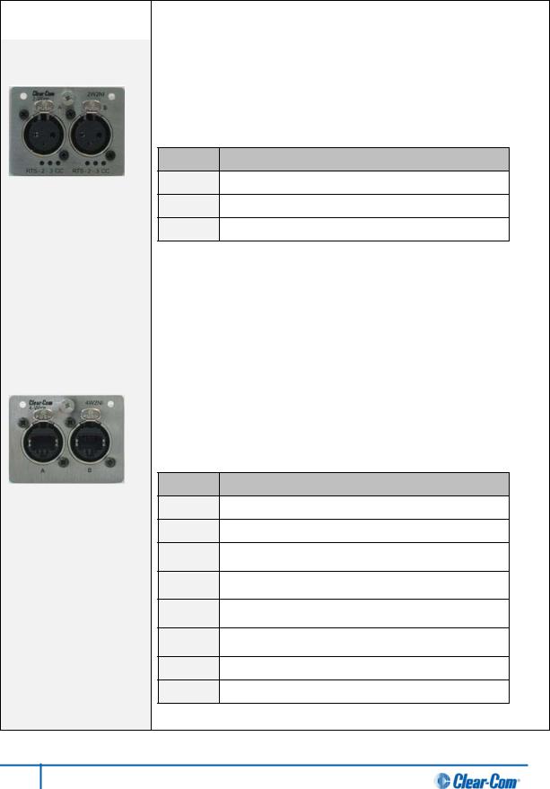
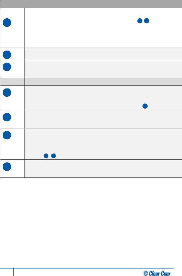
2.2.1 HMS-4X Main Station rear panel: Interface modules
Up to three additional Interface modules (of the same or different types) can be fitted to the extension bay of the main station:
Interface module |
Description |
|
|
Two-wire interface |
Enables interoperability with Tempest, CellCom / FreeSpeak, and HME |
module (HLI-2W2) |
DX210 systems, and both Clear-Com and RTS analog partyline |
|
systems. |
|
The module provides two analog partyline connectors (3 pin female XLR |
|
connectors) with the following pin out: |
Pin Function
1Ground
2Power [Option for RTS mode: power and audio]
3Audio
Table 6: two-wire Interface Module pin out
|
Use HelixNet main station menus to set the module for either RTS or |
|
Clear-Com systems. If RTS mode is selected, you can set either: |
|
• Pin 2 for power and audio. |
|
• Pin 3 for audio. |
|
|
Four-wire interface |
Enables interoperability with the Eclipse digital matrix system and other |
module (HLI-4W2) |
four-wire audio sources (telephone hybrids, AB-120/-100, PA (Public |
|
Address) / SA (Stage Announce) systems. |
|
The module also enables HelixNet-to-HelixNet connections using four- |
|
wire audio ports. Two four-wire connectors (Ethercon type RJ45 socket) |
|
are provided with the following pin out: |
Pin Function
1RS-422 data TX+
2RS-422 data TX-
3Audio to matrix +
4Audio from matrix+
5Audio from matrix-
6Audio to matrix-
7RS-422 data RX+
8RS-422 data RX-
Table 7: four-wire interface module pin out
Table 8: HMS-4X Main Station rear panel: Interface Modules
17 HelixNet Partyline User Guide

2.3 HBP-2X Beltpack
2.3.1 HBP-2X user controls (front and side view)
A
B
C
 D
D
G
E
F
Figure 5: HBP-2X beltpack main controls (front and side view)
18 HelixNet Partyline User Guide
Key to HBP-2X user controls (front and side view)
Feature |
Description |
A |
Menu key. Press firmly (for 2s) to enter Menu mode (see also D F ). To exit Menu |
|
mode, press the Menu key again. |
|
Note: |
|
The display screen times out of Menu mode and displays the channel label(s) if no key |
|
is pressed for 20 seconds. |
BUSB 2.0 (Micro-AB) connector. For software upgrades.
CCasing. Metal casing for robust use. For information about the beltclip, beltloops, and feet, see 2.3.3 HBP-2X beltclip, beltloops and feet (base view).
Keyset
DRotary control. Turn to increase and decrease the volume level for the channel.
In Menu mode, you can turn either of the side-mounted rotary controls to scroll menu items. To select (enter) items, press the right-hand Call key (see F ).
ETalk key. Press to talk to all nodes (intercom devices and systems) listening into the channel. There are two Talk keys on the beltpack, one for each of the supported channels.
FCall key. Press to send a call signal to all nodes (intercom devices and systems) listening into the channel. There are two Call keys on the beltpack, one for each of the supported channels.
In Menu mode, press the right-hand Call key to select (enter) menu items (see also A D ). Use the left-hand Call key to go back one menu level.
GDisplay screen. When the beltpack is not in Menu mode, the labels and volume level for each of the two channels supported by the beltpack are displayed on screen.
Table 9: Key to HBP-2X Beltpack main controls (front and side view)
19 HelixNet Partyline User Guide
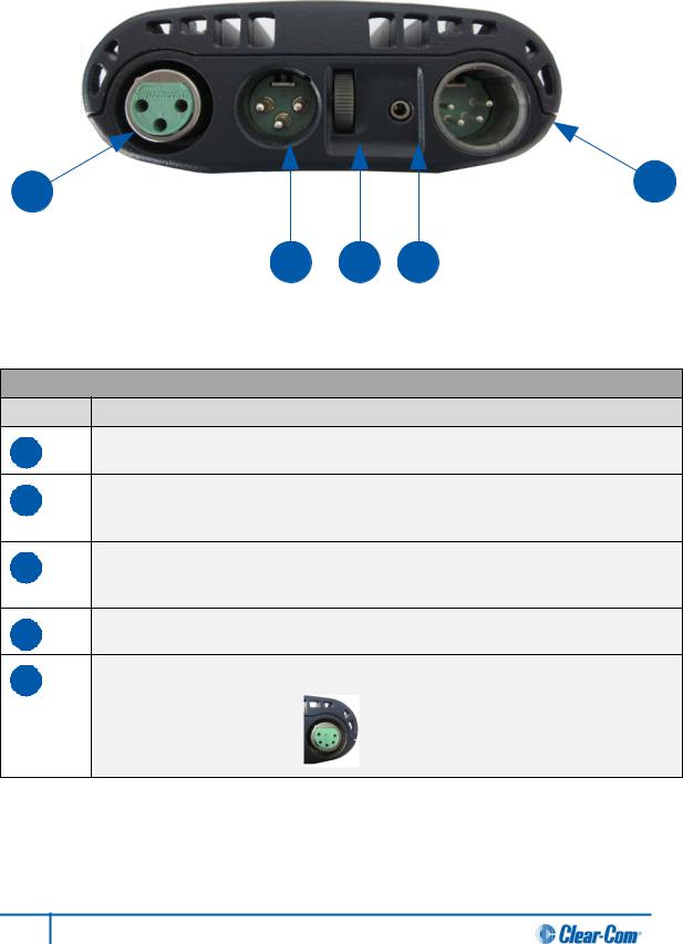
2.3.2 HBP-2X connectors and controls (rear view)
A |
E |
|
B C D
Figure 6: HBP-2X connectors and controls (rear view)
Key to HBP-2X Beltpack (Rear view)
Feature Description
ALine (Partyline) (3-pin female XLR connector).
BLine (Partyline) (3-pin male XLR connector). Pass-thru for ‘daisy chain’ connection (see Figure 9: Example system topologies (layouts)).
CProgram feed (volume) scroll wheel. Turn to increase or decrease the overall volume level of the program feed.
D2.5 mm TRS headset input.
EHeadset connector (4-pin or 5-pin XLR connector (male or female options)). The 4-pin male option is shown.
Example 5-pin female option:
Table 10: Key to HBP-2X Beltpack connectors and controls ( base view)
20 HelixNet Partyline User Guide

2.3.3 HBP-2X beltclip, beltloops and feet (base view)
Figure 7: HBP-2X Beltpack: base view
Key to HBP-2X Beltpack (Base view)
Feature Description
ABeltclip. The beltclip is secured to the unit with three screws, and may be removed, according to your requirements. Use the beltclip to attach the beltpack to a belt or a fixed position.
BBeltloops (one either side). Use to thread through a belt or strap for securing the beltpack to a belt or a fixed position.
CFeet (positions only). The beltpack can also be placed on a level surface (once the beltclip has been removed). To give the beltpack more grip on the surface, attach the four rubber feet supplied with the beltpack.
Table 11: Key to HBP-2X Beltclip, beltloops and feet ( base view)
21 HelixNet Partyline User Guide
3 Installing HelixNet Partyline
This chapter describes how to install your HelixNet Partyline system. It also provides basic guidance on planning your installation.
Tip: For guidance on connecting HelixNet Partyline to other systems, using the optional interface modules, see 8 Connecting to Other Intercom Systems.
Do not plug any non-approved equipment into HelixNet Partyline.
HelixNet Partyline operates at different voltage levels than analog two-wire partyline systems. Do not plug any analog two-wire partyline equipment into the HelixNet partyline ports, as this may cause damage.
If you have damaged analog two-wire partyline equipment in this way, contact Clear-Com for repair options.
For more safety instructions, see 1.2 Important Safety instructions.
22 HelixNet Partyline User Guide
3.1 Planning your HelixNet Partyline installation
3.1.1 Comparing digital with analog cabling
A B
P1 |
P2 |
P3 |
P4 |
C |
|
|
D |
E 


 F
F
P1 P1
P2 P2
P3 P3
P4 P4
PF |
PF |
Figure 8: Analog and digital cabling comparison
23 HelixNet Partyline User Guide
Key to analog and digital cabling comparison diagram
Feature Description
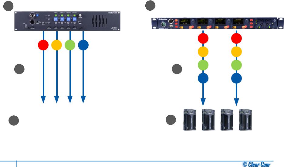
AExample 4-channel analog main station (MS-704 shown).
BHMS-4X Main Station (digital main station).
P1 |
|
Partyline channel 1 |
|
|
|
P2 |
|
Partyline channel 2 |
P3 |
|
Partyline channel 3 |
P4 |
|
Partyline channel 4 |
|
|
Program Feed |
PF |
|
|
|
|
|
CIn a traditional analog partyline system, one cable is dedicated in hardware to each partyline channel. This can make it more difficult to build redundancy or spare capacity into the installation (owing to the number of connectors / cables dedicated to the delivery of channels).
DIn the HelixNet system, one cable can carry multiple channels (all four partyline channels plus a Program Feed). Because one cable can carry all channels, the second connector for each line can either be used for redundancy (flybacks) or for future extensions / changes to the cabling topology (layout).
EExample analog partyline beltpacks (RS-602 shown). Analog beltpacks must be recabled to use alternative channels, requiring the physical re-location of cabling for new configurations.
To aid switching, Clear-Com sells additional switching equipment (the SB-704 and RCS-2700 devices). The RS-602 (6-pin XLR) beltpack requires the YC-36 splitter / combiner to combine 2 channels into a 6-pin configuration, and multi-conductor cables.
The RS-603 (3-pin XLR) beltpack requires a TWC-701 device to combine 2 Clear-Com channels in a single twisted pair.
FHBP-2X Beltpacks. Digital beltpacks can support any two of the four partyline channels (plus Program Feed), wherever they are physically located on the system.
New configurations of beltpacks and channels can be deployed without the physical relocation of assets.
Table 12: Key to analog and digital cabling comparison diagram
Note:
The capabilities of different cable types may impact how far away beltpacks can be placed from the main station, and the topologies you use. For more information about cabling, see
Appendix C:Cabling reference.
24 HelixNet Partyline User Guide
3.1.2 Topologies (layouts)
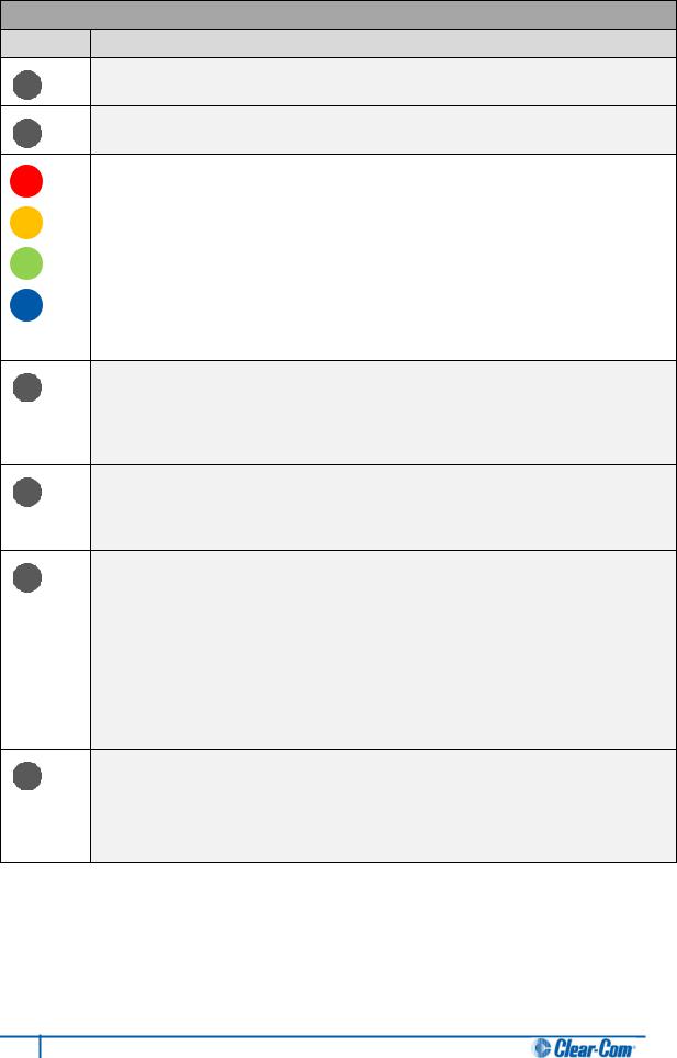
HelixNet Partyline can be deployed using a wide range of topologies, both complex and straightforward. The following table describes three standard types of topology:
Topology |
Description |
|
|
Daisy-chain |
In a daisy-chain topology, the main station is connected to the first |
|
beltpack. The beltpacks are then connected in a series, using the pass-thru |
|
connector on the back / rear of the device to pass on the connection. No |
|
termination is required. |
|
Daisy-chains can be either linear or loop back to the main station to form a |
|
ring. |
|
|
Star |
In a star topology, the main station is connected to a passive (Y) splitter |
|
such as an XLR Bulkhead or Mult-box. The beltpacks are then connected |
|
to the splitter point-to-point. |
|
|
Tree |
A tree topology is a more complex version of the star topology, using |
|
serially connected passive ( Y ) splitters. The beltpacks are connected to |
|
each splitter point-to-point (forming a branch of the tree). |
|
|
|
Table 13: Topology types |
25 HelixNet Partyline User Guide
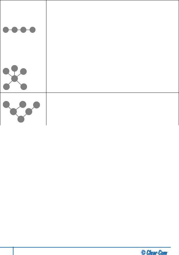
Figure 9: Example system topologies (layouts)
26 HelixNet Partyline User Guide
Key to example system topologies (layouts) diagram
Feature Description
AHMS-4X Main Station (digital main station) (rear panel).
There are two lines (digital partylines) on the main station, each of which can support up to 10 digital HBP-2X beltpacks. There are two connectors (3-pin XLR, male and female) for each line.
BDaisy chained HBP-2X Beltpacks. To create a ‘daisy chain’ of connected beltpacks:
1.Connect the first beltpack to the main station, using either of the 3-pin XLR connectors (female [  ] or male [
  ] ) on the base of the beltpack.
2.Pass on the connection to the second beltpack, using the remaining connector as the ‘pass thru’.
3.Repeat for all beltpacks (up to 10) in the chain. No cable termination is required.
CThe second layout uses an XLR Bulkhead and a Mult-box (passive (Y) splitters) to combine:
•A daisy chain (with optional redundancy flyback).
•Point-to-point connected beltpacks (using the Mult-box).
The complexity and variety of layouts does not restrict physical access to channels.
Because HelixNet Partyline is a digital system, the HBP-2X Beltpacks can access any two of the four available channels (plus a Program Feed), however they are connected to the main station (see Figure 8: Analog and digital cabling comparison).
Table 14: Key to example topologies (layouts)
35 HelixNet Partyline User Guide

3.2 Installing HelixNet Partyline
3.2.1 Environmental information
The recommended temperature ranges for HelixNet Partyline ( the HMS-4X Main Station and HBP-2X Beltpacks) are as follows:
|
Operational status |
Temperature range (recommended) |
||
|
|
|
|
|
|
|
|
Min. |
Max. |
|
|
|
|
|
|
In use (operational) |
|
0 °C |
+50°C |
|
|
|
|
|
|
|
|
-30 °C |
+70°C |
|
In storage (non-operational) |
|||
Table 15: Recommended temperature ranges
Install the HMS-4X Main Station at a site where there is adequate ventilation around the main station. Ensure that the the top and side vents on the device are not blocked.
Note:
To view temperature information on the main station, see 4.8.2 Viewing temperature information.
For safety guidance, see the Safety Instructions at the front of this guide.
3.2.2 Installing the HMS-4X Main Station
The HMS-4X Main Station is a 19” 1U-height device that you can install to either:
•A standard 19” rack.
•A shelf, cabinet or other flat surface.
To enable fitting to a rack, the main station is fitted with rack-mounting ears [  ].
].
For the location of the rack-mounting ears on the main station, see A in
Table 3: Key to HMS-4X Main Station front panel diagram.
28 HelixNet Partyline User Guide
Power up
There is no power switch, button or key on the HMS-4X Main Station. To power up the main station:
1.Connect the power cord [  ] to the power supply connector [
  ] on the main station. Use the cable retaining clip on the main station to secure the power cord. The retaining clip is detached for shipping and must be refitted.
Note:
For the location of the power supply connector on the main station, see A in
Table 5: Key to HMS-4X Main Station rear panel diagram.
2.Connect the power cord to the power source (socket). The main station requires an input voltage between 100 - 240 VAC / 50-60Hz/ 250 watts / T 3.15A H 250 V.
During power up (which takes 15-20 seconds), the front panel display screens momentarily display the Clear-Com logo [  ] until the device is ready for operation.
Only connect power supply to earthed supply sockets. Ensure that the power supply is routed to avoid sharp bends, hot surfaces, pinches and abrasion.
For safety guidance, see the Safety Instructions at the front of this guide.
3.2.3 Installing the HBP-2X Beltpacks
The HBP-2X Beltpack is a device that you can:
•Wear at your belt, using either the beltclip or beltloops.
•Install to a shelf or other flat surface.
•Attach to a pole or other fixed upright position.
Tip: For more information, see 2.3.3 HBP-2X beltclip, beltloops and feet (base view)
Power up
The HBP-2X Beltpack is powered from the (standard mic) cable that connects the device with the HMS-4X Main Station (see below).
29 HelixNet Partyline User Guide

Connecting the HBP-2X Beltpack to the HMS-4X Main Station
To connect the HBP-2X Beltpack to the HMS-4X Main Station:
1.There are two lines (partylines) on the main station, each of which can support up to 10 digital HBP-2X beltpacks. There are two connectors (3-pin XLR, male and female) for each line. Connect the cable to the selected connector [  ] on the main station.
Note:
For the location of Lines 1 and 2 (the powerlines) on the main station, see F G in
Table 5: Key to HMS-4X Main Station rear panel diagram.
2.Connect the cable to the beltpack, using one of the two 3-pin XLR connectors (male and female) on the base / rear of the beltpack.
Tip: For example topologies, see 3.1.2 Example system topologies (layouts).
30 HelixNet Partyline User Guide
Loading...