


 Loading...
CLEAR-COM ENCORE
KB-702/KB-702GM TWO-CHANNNEL SPEAKER STATIONS
I N S T R U C T I O N M A N U A L
KB-702/KB-702GM Two-Channel Speaker Stations Instruction Manual
Part Number: 810492Z Rev. 3
Legal Disclaimer
Copyright © 2013 HME Clear-Com Ltd.
All Rights Reserved
Clear-Com, the Clear-Com logo, and Clear-Com Concert are trademarks or registered trademarks of HM Electronics, Inc. The software described in this document is furnished under a license agreement and may be used only in accordance with the terms of the agreement.
The product described in this document is distributed under licenses restricting its use, copying, distribution, and decompilation/ reverse engineering. No part of this document may be reproduced in any form by any means without prior written authorization of Clear-Com, an HME Company.
Clear-Com Offices are located in California, USA; Cambridge, UK; Montreal, Canada; and Beijing, China. Specific addresses and contact information can be found on Clear-Com's corporate website:
www.clearcom.com
Clear-Com Contacts
Americas and Asia-Pacific Headquarters
California, United States
Tel: +1.510.337.6600
Email: CustomerServicesUS@clearcom.com
Europe, Middle East, and Africa Headquarters
Cambridge, United Kingdom
Tel: +44 1223 815000
Email: SalesSupportEMEA@clearcom.com
Canada Office
Quebec , Canada
Tel: +1 (450) 653-9669
China Office
Beijing Representative Office
Beijing, P.R.China
Tel: +8610 65811360 / 65815577

CONTENTS
OPERATION . . . . . . . . . . . . . . . . . . . . . . . . . . . . . . . . . . 1-1
Introduction . . . . . . . . . . . . . . . . . . . . . . . . . . . . . . . . . . . . . . . . . . . . . . . . . 1-1
Description . . . . . . . . . . . . . . . . . . . . . . . . . . . . . . . . . . . . . . . . . . . . . . . . . . 1-1
Operation . . . . . . . . . . . . . . . . . . . . . . . . . . . . . . . . . . . . . . . . . . . . . . . . . . . 1-2
Front Panel . . . . . . . . . . . . . . . . . . . . . . . . . . . . . . . . . . . . . . . . . . . . . . . . 1-2
Internal Adjustments and Connections . . . . . . . . . . . . . . . . . . . . . . . . . . 1-5
INSTALLATION . . . . . . . . . . . . . . . . . . . . . . . . . . . . . . . 2-1
MAINTENANCE . . . . . . . . . . . . . . . . . . . . . . . . . . . . . . . 3-1
Block Diagram for the KB-702 . . . . . . . . . . . . . . . . . . . . . . . . . . . . . . . . . . 3-1 Block Diagram for the KB-702GM . . . . . . . . . . . . . . . . . . . . . . . . . . . . . . . 3-2 Troubleshooting . . . . . . . . . . . . . . . . . . . . . . . . . . . . . . . . . . . . . . . . . . . . . . 3-3
TECHNICAL SPECIFICATIONS . . . . . . . . . . . . . . . . . . 4-1
KB-702/KB-702GM Two-Channel Speaker Stations . . . . . . . . . . . . . . . . . 4-1
LIMITED WARRANTY. . . . . . . . . . . . . . . . . . . . . . . . . . 5-I
Warranty Period . . . . . . . . . . . . . . . . . . . . . . . . . . . . . . . . . . . . . . . . . . . . . . 5-i
Technical Support. . . . . . . . . . . . . . . . . . . . . . . . . . . . . . . . . . . . . . . . . . . . . 5-i
Warranty Repairs and Returns . . . . . . . . . . . . . . . . . . . . . . . . . . . . . . . . . . . 5-ii
Non-Warranty Repairs and Returns . . . . . . . . . . . . . . . . . . . . . . . . . . . . . . . 5-ii
Extended Warranty. . . . . . . . . . . . . . . . . . . . . . . . . . . . . . . . . . . . . . . . . . . . 5-ii
Service Contract . . . . . . . . . . . . . . . . . . . . . . . . . . . . . . . . . . . . . . . . . . . . . 5-iii
Liability . . . . . . . . . . . . . . . . . . . . . . . . . . . . . . . . . . . . . . . . . . . . . . . . . . . 5-iii
K B - 7 0 2 / K B - 7 0 2 G M |
T W O - C H A N N E L |
i

i i
K B - 7 0 2 / K B - 7 0 2 G M T W O - C H A N N E L S P E A K E R

Please read and follow these instructions before operating this product.
IMPORTANT SAFETY INSTRUCTIONS
1.Read these instructions.
2.Keep these instructions.
3.Heed all warnings.
4.Follow all instructions.
5.Do not use this apparatus near water.
6.Clean only with dry cloth.
7.Do not block any ventilation openings. Install in accordance with the manufacturer’s instructions.
8.Do not install near any heat sources such as radiators, heat registers, stoves, or other apparatus (including amplifiers) that produce heat.
9.Only use attachments/accessories specified by the manufacturer.
10.Use only with the cart, stand, tripod, bracket, or table specified by the manufacturer, or sold with the apparatus. When a cart is used, use caution when moving the cart/apparatus combination to avoid injury from tip-over.
11.Unplug this apparatus during lightning storms or when unused for long periods of time.
12.Refer all servicing to qualified service personnel. Servicing is required when the apparatus has been damaged in any way, such as power-supply cord or plug is damaged, liquid has been spilled or objects have fallen into the apparatus, the apparatus has been exposed to rain or moisture, does not operate normally, or has been dropped.
13.WARNING: To reduce the risk of fire or electric shock, do not expose this product to rain or moisture.
Please familiarize yourself with the safety symbols in Figure 1. When you see these symbols on this product, they warn you of the potential danger of electric shock if the station is used improperly. They also refer you to important operating and maintenance instructions in the manual.
K B - 7 0 2 / K B - 7 0 2 G M T W O - C H A N N E L
i i i
CAUTION
RISK OF ELECTRIC SHOCK
DO NOT OPEN
This symbol alerts you to the presence of uninsulated dangerous voltage within the product's enclosure that might be of sufficient magnitude to constitute a risk of electric shock. Do not open the product's case.
This symbol informs you that important operating and maintenance instructions are included in the literature accompanying this product.
Figure 1: Safety Symbols
EMC AND SAFETY
The KB-702 and KB-702GM stations meet all relevant CE and FCC specifications set out below:
EN55103-1 Electromagnetic compatibility. Product family standard for audio, video, audio-visual, and entertainment lighting control apparatus for professional use. Part 1: Emissions.
EN55103-2 Electromagnetic compatibility. Product family standard for audio, video, audio-visual, and entertainment lighting control apparatus for professional use. Part 2: Immunity.
And thereby compliance with the requirement of Electromagnetic Compatibility Directive 2004/108/EC and Low Voltage Directive 2006/95/EC
This device complies with Part 15 of the FCC Rules. Operation is subject to the following two conditions: (1) this device may not cause harmful interference, and (2) this device must accept any interference received, including interference that may cause undesired operation.
i v
K B - 7 0 2 / K B - 7 0 2 G M T W O - C H A N N E L S P E A K E R

OPERATION
INTRODUCTION
Congratulations and thank you for choosing this Clear-Com product. The KB-702 and KB-702GM two-channel speaker stations are powerful, user-friendly units that can serve as versatile intercom stations.
Please read this manual completely to better understand the functions of these products. For questions not addressed in this manual, contact the dealer or Clear-Com directly. Clear-Com applications support and service people are ready to help.
DESCRIPTION
The Clear-Com KB-702 is a two-channel speaker station ideal for theatre, live performances, industrial applications, and small TV facilities. It features excellent speech intelligibility even in high-noise environments and can be tailored to your needs through its programmable options.
In addition, the Clear-Com KB-702GM contains a jack for an optional Clear-Com gooseneck panel microphone and a close-in, voice-controlled circuit (VOX). This circuit allows automatic, alternate dipping of the panel microphone and the speaker in response to conversation.
Selectable two-channel talking and/or listening allows the operator to communicate on either of the intercom channels. The dual-action talk button is electronic momentary or latching. Monitoring can be done through the headset, the integral speaker, or both at once. The KB-702 offers both visual and audible call signaling to attract the attention of operators. The remote mic kill (RMK) feature on main stations will turn off any open mics on the KB-702.
A balanced program input allows the monitoring of external audio using the headset or speaker. This program input can also be used as a paging function.
The KB-702 speaker station accepts dynamic headsets. A sidetone control allows the operator to vary the level of his/her own voice as heard in the headset and speaker.
The integral speaker can be turned on or off by a convenient front panel switch. An automatic speaker dipping circuit will lower the level of the speaker whenever the talk button is activated. This feature helps minimize acoustical feedback.
The KB-702 receives power from the Clear-Com intercom line. The unit mounts either in a standard four-gang electrical outlet box or in an optional Clear-Com four-gang V-box. The extra-thick front panel and compact surface-mount circuitry maintains legendary Clear-Com ruggedness. The two intercom channels connect to a plug-on screw terminal strip. Male and female
K B - 7 0 2 / K B - 7 0 2 G M |
T W O - C H A N N E L |
1 - 1 |
3-pin XLR connectors are provided on the four-gang V-box for an inline connection to one of the intercom channels.
The optional EB7-TW daughter board module can be installed to provide an interface to two intercom channels on a single microphone cable. Also, the EB7-4W four-wire daughter board module is available to allow long-distance connections using separate pairs of wire for send audio and receive audio. The EB7-4W four-wire option supports two-channel operation.
The KB-702 and KB-702GM are compatible with all Clear-Com party-line intercoms.
OPERATION
Normal operation of the KB-702 speaker station requires access only to the front panel controls. The controls located elsewhere on the unit are intended to be set-and-forget in nature. For intercom operation, set the listen level control to the desired level and press the talk button when talking. If a headset or handset is used, set the sidetone control for each channel for the desired amount of sidetone in the earphone. If a hand-held push-to-talk mic is used, or if the panel mic is used on the KB-702GM, set the sidetone controls for minimum feed-through to the speaker to prevent acoustic feedback.
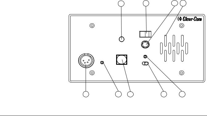
FRONT PANEL
The controls, indicators, and connectors found on the KB-702 and KB-702GM front panels are shown in the following figures and are described by the following text. The numbers in the left column refer to Figure 1-1 and Figure 1-2.
2 |
9 |
4 |
3 |
Channel Select
A |
B |
Call
Volume
Headset
Program Level
|
Off |
On |
Sidetone |
Talk |
Speaker |
|
2-Channel
Speaker Station
KB-702
10 |
5 |
1 |
7 |
6 |
Figure 1-1: KB-702 Front Panel
1 - 2 |
K B - 7 0 2 / K B - 7 0 2 G M T W O - C H A N N E L S P E A K E R |

11 |
12 |
8 |
2 |
9 |
4 |
3 |
Microphone |
Channel Select |
|
|
||
VOX |
|
|
A |
|
B |
|
|
Volume |
Panel Mic |
|
|
Call |
|
|
Headset |
|
|
Headset |
Program Level |
|
Sidetone |
|
Speaker |
|
|
|
|
Off |
On |
Talk |
|
|
2-Channel
Speaker Station
KB-702GM
10 |
5 |
1 |
7 |
6 |
Figure 1-2: KB-702GM Front Panel
1.Talk Button and Indicator: The talk button activates the microphone feed to the selected intercom channel. It has a dual action (momentary or latching) depending upon how the button is pressed. If desired, the latching function can be defeated using an internal option switch. The following describes the various functions of this button.
•MOMENTARY: Press and hold the talk button while you are speaking. Release it when you are finished. The button lights amber when the talk function is active and blue when it is inactive.
•LATCHING: Press the button quickly to latch the talk function. Press the button again to turn off the talk function.
•VOX INDICATION: On the KB-702GM, when the VOX feature is enabled, the talk button illuminates amber to indicate an active talk, and the VOX light illuminates amber to indicate that the panel microphone is in use. This will automatically dip the speaker.
2.Call Button and Light: Pressing the call button will send a call signal on the selected channel. All the call lights on that channel will then flash. Call signals can also be sent while talking if required. The call button will light when pressed, or whenever a call signal is present on the selected channel. An internal option jumper can be set to allow the call button to light when a call signal is present on either channel.
3.Tone Alert: An audible tone alert can be enabled to sound when a call signal is received on the selected channel or either channel. This can be useful when the operator’s attention has been drawn away from the KB-702 indicator panel. The audible tone alert level can be adjusted or turned off by an internal control. The tone alert will not sound if a call
K B - 7 0 2 / K B - 7 0 2 G M T W O - C H A N N E L |
1 - 3 |

signal originates at the KB-702 station or if the speaker on/off switch is turned off. The tone alert plays through both the speaker and headset if the speaker on/off switch is turned on.
4.Volume Control: Turn this control to set the volume required on the speaker or headset. This control does not affect the tone alert level or the program input level.
5.Sidetone Control: Sidetone is the level of your own voice that you hear while talking on the intercom. Setting a comfortable level of sidetone will ensure that the intercom line sounds alive and also helps you modulate your voice relative to other voices on the line.
Typically, different sidetone null settings are needed depending upon whether you are using the speaker. Use one of the following procedures to correctly set the sidetone level control.
Sidetone Adjustment Procedure for Headset:
1.Set the intercom level control to a comfortable level by having someone talk to you from another station.
2.Press the talk button and speak into the microphone while turning the sidetone null control slowly back and forth until you hear your voice at a comfortable level in the headset.
Sidetone Adjustment Procedure for Gooseneck Mic (KB-702GM only) or hand-held push-to-talk mic with the speaker turned on:
1.Set the VOX control fully counterclockwise to disable this feature.
2.Set the intercom level control to a comfortable level.
3.Press the talk button and speak into the microphone while turning the sidetone null control slowly back and forth. There should be a point where your voice (and any accompanying acoustic feedback) disappears. This is the null point.
4.Readjust the VOX control. (Refer to the VOX control paragraph in this section.)
6.Program Level Control: Adjust the program level control to set the program audio level heard in the headset or panel speaker.
Note: Do not force the trimpots past their stop points. This will damage them.
7.Speaker On/Off Switch: The speaker on/off switch turns the front panel speaker on or off. This switch also controls whether the tone alert is heard through the speaker. The speaker volume will automatically dip whenever the talk function is set, unless the VOX function is disabled.
8.Mic Select Switch (KB-702GM only): The mic select switch selects whether the panel microphone or the headset microphone is active. If the VOX feature is enabled, it is only operational when the panel microphone is active.
9.Channel Switch: This switch selects whether the speaker station is active on intercom channel A or channel B.
10.Headset Connector: The headset connector is located on the front panel. All Clear-Com headsets are recommended for use with the KB-702. The Clear-Com handheld push-to-talk microphone will also plug into the
1 - 4 |
K B - 7 0 2 / K B - 7 0 2 G M T W O - C H A N N E L S P E A K E R |
Loading...