


OWNER’S MANUAL
SSP-75
Preamplifier/Surround
Sound Processor
V1.0

SAFETY INFORMATION
1.To prevent fire or shock hazard, do not expose the SSP-75 to water or moisture.
2.Do not place the SSP-75 close to any heatproducing device such as a radiator, stove, etc..
3.Connect the SSP-75 only to an AC source of the proper voltage. The shipping container and the rear panel serial number tag will stipulate the proper voltage. Use of any other voltage willalmost certainly damage the unit and will void the warranty.
4.Do not open the SSP-75 for any reason, as there are no user serviceable parts inside. An open unit, particularly if it is still connected to an AC source, presents a potentially lethal shock hazard. Refer all questions to authorized service personnel only.
5.If the SSP-75 will be out of use for an extend period of time (vacation, etc.), unplug the power cord from the AC source to prevent any chance of problems from a voltage surge.
CE NOTICE
All of us at Classé take extreme care to insure that your purchase will become a prized investment. We are proud to inform you all Classé Audio components have been officially approved for
the European Community (CE) mark under CE Certificate Number C401CLA1.MGS granted on 18 July, 1996.
This means that your Classé product was subjected to the most rigorous manufacturing
and safety tests in the world. The CE mark certifies that your purchase meets or exceeds all European Community requirements for unit-to-unit consistency and consumer safety.
The SSP-75 is manufactured under license from Dolby Laboratories Licensing Corporation. It is additionally licensed under one or more of the following patents: U.S. number 3,959,950, Canadian numbers 1,004,603 and 1,037,877.
Manufactured under license from Lucasfilm Ltd. U.S. patent numbers 5,043,970; 5,189,703; and 5,222,059. European patent 0 323 830. Other patents pending.
Additionally, the SSP-75 is manufactured under license from Digital Theater Systems, Inc.
Dolby® Pro Logic®, and Dolby Digital® are registered trademarks of Dolby Laboratories Licensing Corporation.
DTS® is a registered trademark of Digital Theater Systems, Inc.
Lucasfilm and THX are trademarks of Lucasfilm Ltd. All rights reserved.
THANK YOU FROM EVERYONE AT CLASSÉ
Thank you for purchasing the Classé Audio SSP-75 Preamplifier/Surround Sound Processor.
We take great pride in offering components that combine exceptional sonic performance and longterm reliability. To do that, we have invested in extraordinary design and manufacturing facilities. We trust that you will enjoy your purchase for many years to come.
CLASSÉ DESIGN PHILOSOPHY
All of our components benefit from the same rigorous design goal: All Classé products must reproduce music with the harmonic and spatial integrity typical of fine instruments heard in a live, unamplified performance.
Single Circuit Design
To this end, we make extensive use of carefully optimized versions of the same basic circuit precisely matched to specific power requirements. This means that all Classé line level components and power amplifiers benefit from years of refinement. However, our efforts do not stop here.
Listening: The Critical Design Element
Once we determine general circuit values for a particular application, we listen carefully while exchanging and mixing different parts (transistors, capacitors, wiring, PC boards, etc.) and adjusting specific operating voltages within proper engineering ranges.
Extended Real-World Lifespan
Every Classé component, even the most affordable, benefits from our painstaking approach to design parameters. The result is an optimum balance between the often-conflicting demands of exceptional performance and long-term reliability. Our most expensive components gain from even tighter tolerance parts and highly segmented and exceptionally robust power supplies with large reserve-current capabilities.
Our Pride in Manufacturing, Your Pride in Ownership.
We build all of our components to the highest possible standards. From multi-layer glass-epoxy circuit boards to the massive faceplates, every Classé product is a tribute to both the art and science of sound reproduction. We hope that you derive as much pleasure and satisfaction in using your Classé as we did in producing it.
ABOUT THIS MANUAL
The Classé SSP-75 is a very sophisticated preamplifier/processor. Even so, although complete understanding of the SSP-75’s many capabilities may take some study, its elegant design and intuitive interface invites daily use by even the technically challenged.
We strongly urge you to read this Manual carefully before you connect and use the SSP-75 in your home theater system. You’ll find answers to almost all of your questions in these pages. That knowledge will greatly reduce your efforts as you configure your system to take best advantage of the SSP-75’s enormous potential.
We’ve organized the Manual for both the experienced installer and the novice user.
The Installation Overview (Section 2) is written for those with technical experience. It provides an inclusive picture of the SSP-75’s capabilities and suggests several effective system configuration strategies.
The following Sections supply step-by-step instructions to help the less technical user configure and use the SSP-75 effectively.
As in all such efforts, a little patience will go a long way to reducing the chances for frustration. Remember, it took many talented people a long time to design the SSP-75 and you can’t be expected to learn everything about it in one evening!
So relax. And enjoy. You’re about to enter a wonderful world of high-performance surround sound.
2

CONTENTS |
|
|
|
|
|
2.1.1 |
CONNECTION TO POWER AMPLIFIER(S) 7 |
6.2.1 |
SELECT FROM THE LIBRARY 13 |
|
||||||||
|
|
|
|
|
|
|
2.1.2 |
AUDIO SOURCE COMPONENTS 7 |
6.2.2 |
PERSONALIZE A NAME 13 |
|
|
||||||
|
SAFETY INFORMATION |
2 |
|
|
2.1.3 |
VIDEO SOURCE COMPONENTS |
7 |
6.2.3 |
INSTRUCTIONS 13 |
|
|
|||||||
|
CE NOTICE 2 |
|
|
|
2.1.3.1 |
DIGITAL OR ANALOG? 8 |
|
|
6.3 |
COMPONENT VIDEO 13 |
|
|
||||||
|
THANK YOU 2 |
|
|
|
2.1.3.2 |
LASER DISC CONNECTION |
8 |
|
6.3.1 |
COMPONENT SETUP INSTRUCTIONS 14 |
||||||||
|
CLASSÉ DESIGN PHILOSOPHY |
2 |
|
2.1.3.3 |
DTS CAPABILITY 8 |
|
|
|
6.4 |
INPUT SETUP |
14 |
|
|
|||||
|
ABOUT THIS MANUAL |
2 |
|
|
2.1.4 |
ANALOG ONLY SOURCES |
8 |
|
6.4.1 |
INPUT SENSITIVITY SETUP |
14 |
|
||||||
|
|
|
|
|
|
|
2.1.5 |
VIDEO SOURCE COMPONENTS |
|
6.4.2 |
ADJUSTING INPUT SENSITIVITY |
14 |
||||||
SECTION 1 |
|
|
|
|
|
|
|
CONNECTIONS 8 |
|
|
|
6.4.3 |
INPUT LEVEL SETUP 14 |
|
|
|||
|
|
|
|
|
|
|
2.1.5.1 |
VIDEO INPUT SELECTION 8 |
|
6.4.4 |
METER SETUP |
14 |
|
|
||||
|
INPUTS, OUTPUTS AND CONTROLS |
4 |
2.1.5.2 |
VIDEO OUTPUTS 8 |
|
|
|
6.4.5 |
AUTO CALIBRATION OF INPUT |
14 |
||||||||
1.1 |
FRONT PANEL 4 |
|
|
|
2.1.5.3 |
COMPOSITE VS. S-VIDEO |
8 |
|
6.4.5.1 |
A.CAL ADVISE 14 |
|
|
||||||
1.1.1 |
MODE BUTTON 4 |
|
|
|
|
|
|
|
|
|
6.5 |
SPEAKER SETUP 15 |
|
|
||||
1.1.2 |
INPUT–AUDIO BUTTON |
4 |
|
|
|
SECTION 3 |
|
|
|
6.5.1 |
SPEAKER SETUP DISCUSSION 15 |
|||||||
1.1.3 |
INPUT–SOURCE BUTTON 4 |
|
|
|
|
|
|
|
|
6.5.2 |
SPEAKER SETUP 15 |
|
|
|||||
1.1.4 |
CLIP AND FORMAT LED INDICATOR |
4 |
|
|
SYSTEM CONFIGURATION |
9 |
|
6.5.2.1 |
MAIN DISCUSSION 15 |
|
|
|||||||
1.1.5 |
STANDBY BUTTON AND LED |
|
|
3.1 |
THE MENU SYSTEM |
9 |
|
|
6.5.2.2 |
CENTER DISCUSSION 15 |
|
|
||||||
|
INDICATOR 4 |
|
|
|
3.1.1 |
INPUT SETUP 9 |
|
|
|
6.5.2.3 |
SURROUND DISCUSSION 15 |
|
||||||
1.1.6 |
PANEL INFORMATION DISPLAY |
4 |
|
3.1.2 |
SPEAKER SETUP 9 |
|
|
|
6.5.2.4 |
SUBWOOFER DISCUSSION |
15 |
|
||||||
1.1.7 |
MEMORY BUTTON 4 |
|
|
|
3.1.3 |
LEVEL CALIBRATION |
9 |
|
|
6.5.2.5 |
BASS LIMITER |
15 |
|
|
||||
1.1.8 |
MODE BUTTON 4 |
|
|
|
3.1.4 |
DELAY SETUP 9 |
|
|
|
6.5.2.6 |
EXIT SPEAKER SETUP 16 |
|
|
|||||
1.1.9 |
MASTER LEVEL CONTROL 4 |
|
|
3.1.5 |
OSD SETUP 9 |
|
|
|
6.6 |
LEVEL CALIBRATE 16 |
|
|
||||||
1.2 |
REMOTE CONTROL WAND 4 |
|
|
3.1.6 |
SYSTEM SETUP 9 |
|
|
|
6.6.1 |
MANUAL CALIBRATION 16 |
|
|||||||
1.2.1 |
DISP |
5 |
|
|
|
|
3.1.7 |
MODE SELECTION 9 |
|
|
|
6.6.2 |
AUTO CALIBRATION 16 |
|
|
|||
1.2.2 |
SLEEP |
5 |
|
|
|
|
3.2 |
CONFIGURATION PROCEDURES |
9 |
6.6.2.1 |
PRESS A.CAL |
16 |
|
|
||||
1.2.3 |
STANDBY 5 |
|
|
|
3.2.1 |
INPUT CONFIGURATION 9 |
|
6.7 |
DELAY SETUP |
16 |
|
|
||||||
1.2.4 |
A.CAL 5 |
|
|
|
3.2.2 |
SOURCE CONFIGURATION |
9 |
|
6.7.1 |
MANUAL DELAY SETUP 17 |
|
|||||||
1.2.5 |
STATUS |
5 |
|
|
|
3.2.3 |
SYSTEM SETUP 9 |
|
|
|
6.7.2 |
AUTOMATIC DELAY SETUP |
17 |
|
||||
1.2.6 |
<AUDIO |
|
|
|
|
3.2.4 |
MEMORY 9 |
|
|
|
6.8 |
OSD SETUP 17 |
|
|
||||
1.2.7 |
AUDIO> |
5 |
|
|
|
|
|
|
|
|
|
6.8.1 |
OSD DISCUSSION 17 |
|
|
|||
1.2.8 |
THX 5 |
|
|
|
|
|
SECTION 4 |
|
|
|
6.8.2 |
OSD COMPONENT SETUP |
17 |
|
||||
1.2.9 |
COMP 5 |
|
|
|
|
|
|
|
|
|
6.9 |
SYSTEM SETUP 17 |
|
|
||||
1.2.10 |
<MODE |
5 |
|
|
|
|
|
GETTING STARTED 10 |
|
|
6.9.1 |
FACTORY RESET 17 |
|
|
||||
1.2.11 |
MODE> 5 |
|
|
|
4.1 |
UNPACKING THE SSP-75 10 |
|
6.9.2 |
REMOTE ZONE VOLUME CONTROL 17 |
|||||||||
1.2.12 |
TRIM |
5 |
|
|
|
|
4.2 |
OPTIMAL PLACEMENT 10 |
|
|
|
|
|
|
|
|
||
1.2.13 |
/\ 5 |
|
|
|
|
|
4.3 |
VENTILATION 10 |
|
|
|
|
SECTION 7 |
|
|
|
||
1.2.14MENU 5
1.2.15 |
< |
5 |
|
|
|
|
|
|
|
SECTION 5 |
|
|
|
|
|
OPERATING THE SSP-75 18 |
|
|||
1.2.16 |
ENTER |
5 |
|
|
|
|
|
|
|
|
|
|
|
7.1 |
THE INFORMATION DISPLAY SCREEN |
18 |
||||
1.2.17 |
> |
5 |
|
|
|
|
|
|
|
|
SYSTEM HOOKUP 10 |
|
|
|
7.1.0 |
INTRODUCTION |
18 |
|
||
1.2.18 |
\/ |
5 |
|
|
|
|
|
|
5.1 |
INTRODUCTION 10 |
|
|
|
7.1.1 |
SOURCE NAME |
18 |
|
|||
1.2.19 |
DIRECT ACCESS KEYS 5 |
|
|
|
5.2 |
CONNECTING THE SSP-75 |
|
|
|
7.1.2 |
MODE INDICATOR 18 |
|
||||||||
1.2.20 |
ZONE |
5 |
|
|
|
|
|
|
|
TO YOUR POWER AMPLIFIER(S) 10 |
|
|
7.1.3 |
AUDIO INPUT 18 |
|
|||||
1.2.21 |
MUTE |
5 |
|
|
|
|
|
5.2.1 |
LEFT AND RIGHT FRONT AMPLIFIER(S) |
10 |
7.1.4 |
MASTER LEVEL INDICATOR 18 |
|
|||||||
1.2.22 |
\/ VOLUME |
5 |
|
|
|
|
5.2.2 |
CENTER CHANNEL AMPLIFIER 11 |
|
|
7.1.5 |
OTHER DISPLAY INFORMATION 18 |
|
|||||||
1.2.23 |
/\ VOLUME |
5 |
|
|
|
|
5.2.3 |
LEFT AND RIGHT SURROUND AMPLIFIERS 11 |
7.1.6 |
CLIP INDICATOR |
18 |
|
||||||||
1.3 |
REAR PANEL 6 |
|
|
|
|
5.2.4 |
SUBWOOFER CONNECTIONS 11 |
|
|
7.2 |
TRIM MODE OPERATION 18 |
|
||||||||
1.3.1 |
INPUT CONECTIONS 6 |
|
|
|
5.3 |
CONNECTION COMPONENTS TO THE |
|
7.2.0 |
INTRODUCTION 18 |
|
||||||||||
1.3.1.1 |
ANALOG AUDIO INPUTS |
6 |
|
|
|
|
SSP-75, SYSTEM SETUP STRATEGY |
11 |
7.2.1 |
TRIM OPERATION 18 |
|
|||||||||
1.3.1.2 |
5.1 ANALOG AUDIO INPUTS |
6 |
5.3.1 |
AUDIO CONSIDERATIONS |
11 |
|
|
7.3 |
OPERATION OF THE REMOTE ZONE |
18 |
||||||||||
1.3.1.3 |
DIGITAL AUDIO INPUTS |
6 |
|
|
5.3.1.1 |
TYPES OF AUDIO INPUTS |
11 |
|
|
7.3.1 |
CONTROL ZONE FROM ZONE AREA |
19 |
||||||||
1.3.1.4 |
VIDEO INPUTS 6 |
|
|
|
|
5.3.1.2 |
PROGRAMMABLE CHARACTERISTICS |
11 |
7.3.2 |
CONTROL ZONE FROM MAIN AREA |
19 |
|||||||||
1.3.2 |
OUTPUT CONNECTIONS |
6 |
|
|
5.3.1.3 |
INPUT ALLOCATION 11 |
|
|
|
7.3.3 |
CONTROL MAIN AREA FROM ZONE |
19 |
||||||||
1.2.3.1 |
MAIN AUDIO OUTPUTS |
6 |
|
|
5.3.1.4 |
CHANNEL CONTINUITY 11 |
|
|
7.4 |
MODE SELECTION 19 |
|
|||||||||
1.3.2.2 |
RECORD AND ZONE AUDIO OUTPUTS 6 |
5.3.1.5 |
CABLE CHOICES 11 |
|
|
|
7.4.0 |
INTRODUCTION |
19 |
|
||||||||||
1.3.2.3 |
RECORD OUT 6 |
|
|
|
|
5.3.2 |
VIDEO CONSIDERATIONS |
11 |
|
|
7.4.1 |
DTS CINEMA 19 |
|
|||||||
1.3.2.4 |
DIGITAL OUTPUTS |
6 |
|
|
|
5.4 |
RECORDING AUDIO/VIDEO 12 |
|
|
7.4.2 |
DTS MUSIC 19 |
|
|
|||||||
1.3.2.5 |
S-VIDEO OUTPUTS |
7 |
|
|
|
5.4.1 |
RECORDING AUDIO/VIDEO ANALOG |
12 |
7.4.3 |
PARTY |
19 |
|
|
|||||||
1.3.2.6 |
COMPOSITE VIDEO OUTPUTS |
7 |
5.4.2 |
RECORDING ANALOG AUDIO ONLY |
12 |
7.4.4 |
STEREO |
19 |
|
|
||||||||||
1.3.2.7 |
IR REMOTE CONNECTORS |
7 |
|
5.4.3 |
RECORDING DIGITAL AUDIO/VIDEO |
12 |
7.4.5 |
MONO |
19 |
|
|
|||||||||
1.3.2.8 |
DC OUTPUT CONNECTIONS |
7 |
5.4.4 |
RECORDING DIGITAL AUDIO ONLY |
12 |
7.4.6 |
DOLBY DIGITAL |
19 |
|
|||||||||||
1.3.2.9 |
MISCELLANEOUS |
7 |
|
|
|
5.4.5 |
PATIENCE IS A VIRTUE 12 |
|
|
|
7.4.7 |
DOLBY PRO LOGIC 19 |
|
|||||||
|
|
|
|
|
|
|
|
|
|
|
|
|
|
|
7.4.8 |
NOTE: THX FEATURES 19 |
|
|||
SECTION 2 |
|
|
|
|
|
|
|
SECTION 6 |
|
|
|
7.6 |
FIRST AID 19 |
|
|
|||||
|
|
|
|
|
|
|
|
|
|
|
|
|
|
|
||||||
|
INSTALLATION OVERVIEW |
7 |
|
|
|
SETUP PROCEDURE 13 |
|
|
|
|
APPENDIX A |
|
|
|
||||||
2.1 |
SYSTEM HOOKUP: REAR |
|
|
|
6.1 |
INTRODUCTION 13 |
|
|
|
|
|
|
|
|
|
|||||
|
PANEL CONNECTIONS 7 |
|
|
6.2 |
CUSTOM NAME 13 |
|
|
|
|
|
THX INFORMATION 20 |
|
||||||||
3
SECTION 1:
INPUTS, OUTPUTS AND CONTROLS
Use the drawings in this section as your guide to the SSP-75. They show the locations of all controls, inputs, outputs, remote keys – in short, everything you need to know about your new preamplifier/surround sound processor. Read the notes under each diagram carefully. You’ll find capsule explanations of all its important features.
Once you have read them, you’ll understand most of the SSP-75’s capabilities.
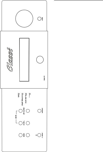
1.1 FRONT PANEL
View page to the Left For Front Panel Controls and Readouts
1.1.1 MODE BUTTON
THESE buttons select up and down from the available SSP-75 operating modes the mode (format) that will be utilized for the audio portion of the currently selected SOURCE. Selection is made in the following sequence: Cinema, Music, Party, Mono (Center), and Stereo. Utilizing the two buttons you can quickly arrive at the mode you desire. When in Cinema mode either DOLBY PRO LOGIC, DOLBY DIGITAL (AC3) or DTS is selected automatically, depending upon the program material available on the active audio input.
1.1.2 INPUT–AUDIO BUTTON
THESE two buttons select up and down from all the available analog or digital AUDIO INPUTs the input that will be utilized for the currently selected SOURCE. The buttons would generally only be used during setup to attach the correct AUDIO input
to one of the twelve SOURCEs. (SOURCEs may be personalized but they are, by default: AUDIO 1 through AUDIO 6 and VIDEO 1 through VIDEO 6). The audio inputs ‘wrap’ from COAXIAL1, to COAXIAL 2, to COAXIAL 3, to COAXIAL 4, to OPTICAL 1, to OPTICAL 2, to AES/EBU, to RF
DEMOD (For external RF demodulator), to ANALOG and to EXT 5.1. (EXT 5.1, meaning External 5.1,
is utilized to input the six preprocessed analog channels available from some DVD players. These analog signals go directly through the SSP-75 without being processed in any way).
There are twelve two channel Analog audio inputs. Each pair is permanently attached to a particular AUDIO (1 – 6) or VIDEO (1 – 6) input. (Analog 6 input is only Balanced (XLR) while all the others are pairs of single-ended (RCA) connectors). When ANALOG is selected only the attached analog input is played. Any of the seven digital inputs may be attached to any of the twelve available SOURCEs. One digital input may in fact be attached to multiple SOURCEs. (Each SOURCE may have attached only one digital audio (or none) plus the associated analog audio input. The SSP-75 will automatically play the ‘live’ audio source for any selected source. If both analog and digital audio
sources are ‘live’ it will automatically select and play the digital input unless ANALOG has been selected as the default audio input.
1.1.3 INPUT–SOURCE BUTTON
THESE pushbuttons work the same way as the Audio buttons described above; selecting
an audio or an audio/video SOURCE for output to the amplifiers and video projector (or TV). These pushbuttons select an audio/video SOURCE by stepping from VIDEO 1 through VIDEO 6 or an audio-only SOURCE from AUDIO 1 through AUDIO 6.
Each press of these buttons changes the source to the next or previous input. For example, if you are enjoying the AUDIO 1 input, pressing the upper
‘SOURCE’ button will step to AUDIO 2. Conversely, pressing the lower ‘SOURCE’ button while using AUDIO 1 will select VIDEO 6. (Any of the twelve ‘SOURCE’ selections can be renamed utilizing functions only available on the remote control wand).
1.1.4 CLIP AND FORMAT LED INDICATORS
CLIPPING: The top LED of these four LEDs glows red to indicate the SOURCEs analog input is being clipped (over-driven). This event would indicate the sensitivity of the driven input is set too high.
FORMAT: The remaining three LEDs indicate the Surround Format of the signal on the audio input. The SSP-75 recognizes the signal on the digital or analog input and automatically selects the correct format to use to properly replay the signal. The three LEDs indicate which method is present: Dolby Pro logic, Dolby Digital or dts.
1.1.5 STANDBY BUTTON AND LED INDICATOR
When the green LED is lit the ‘Main’ outputs of the SSP-75 are in ‘Standby’ or ‘Off’. When in Standby the ‘Main’ 12 volt DC trigger is Off and there is no output from the Main outputs. The processor is waiting for a signal from the remote control or from the standby button to turn on. When the button is pushed to activate the SSP-75 the standby LED goes out and the display also lights briefly with a ‘Classé SSP-75’ readout. All circuits are powered on, and 12 volts DC is present at the Main 3.5 mm DC jack on the rear panel.
The remote Zone can continue to play when the Main Zone is in Standby, and the Zone can put into or removed from Standby. Different SOURCEs can be selected for the remote Zone output when
the remote Zone is on. There is no ‘Standby’ indication on the front panel for the remote Zone.
4
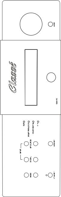
1.1.6 PANEL INFORMATION DISPLAY
The two lines of information displayed, and the lit LEDs on the face of the SSP-75 combine to provide a comprehensive view of its current operating parameters. All set-up procedures may also be performed utilizing only the panel display, though it is easier using the onscreen OSD method. The first line displays the SOURCE on the left and selected MODE on the right. ‘THX’ is displayed in the middle of this line when you use the remote control wand to select THX playback for any SOURCE.
The second line displays on the left where the currently connected audio input, and the output level, (or ‘Mute’) is displayed on the right end of the line.
While the Remote Zone is being accessed the word ‘ZONE’ appears in the middle of lower line, and all the information displayed in the window relates to the operation of the Remote Zone. The layout of the information is the same as above.
1.1.7 MEMORY BUTTON
The purpose of this button is enable quick memorization of the current setup of the playing SOURCE. The audio input and selected format are memorized along with any video input. The next time the SOURCE is selected the setup will be the same. (Any previously memorized settings for the SOURCE are erased).
1.1.8 MUTE BUTTON
This button fully mutes the SSP-75’s main outputs and also can be used to mute the Remote Zone outputs when Remote Zone control is activated. A second push of the Mute button restores the previously selected operating levels. Record output is always unaffected. The Mute button provides a convenient way to instantly lower the volume when answering the telephone.
NOTE: Turning the volume up with the volume knob (or remote control wand), will remove muting, but turning down the volume while in mute mode will not remove muting. However; if you reduce the volume while the audio output is muted, when muting is removed the new lower volume level will be present. (There is no indication of the volume change on the panel display. If you are using a video output with OSD the reduced volume will be displayed briefly while the volume is being reduced). Muting can be removed either with the mute button or by turning up the volume slightly.
1.1.9 MASTER LEVEL CONTROL
This large knob changes the levels of all the active channels in either the main room or the remote zone. In the main room each loudspeaker’s relative loudness stays in perfect balance with all other speakers as programmed during setup. The Main Information Display shows the master level setting in numbers from ‘-80’ (virtually no output) to ‘+30’ (maximum output).
5

1.2 REMOTE CONTROL WAND
The keys on the SSP-75 remote are laid out in an easy to use pattern. The first three rows, from DISP through MODE > are a set of eleven buttons with a variety of relatively unrelated tasks which, with the exception of the STANDBY button, you will probably use infrequently. The second section is made up of the three rows beginning with TRIM and ending with the single key \/. These seven keys are used during the set up of the basic parameters of the operation of the surround processor. The remaining five rows, beginning with AV1 and ending with the VOLUME /\ key are the keys you will find yourself using most often. They include all the direct access keys, the MUTE and VOLUME up and down keys.
1.2.1 DISP
The first press causes the display to dim by about 90%, a second press returns the display to its normal brightness. (While dimmed, the display will brighten when any other button is pressed on the remote and will return to the dim setting five seconds after you have stopped pressing buttons). The dim mode will continue indefinitely until the dim button is pressed again.
NOTE: It does not reset when STANDBY is pressed. It will reset to bright if the rear panel on/off switch is cycled off and on, or if the AC supply is interrupted
1.2.2 SLEEP
Causes a fifteen minute timer to start, to automatically put the SSP-75 into standby. Up to five more presses cause the timer to increase the time period by 15 minutes and a seventh press will exit the sleep timer program. At the end of the programmed time period the SSP-75 will enter its stand-by mode. Any equipment depending on the 12 volt trigger from the SSP-75 will also ‘turn off’. The display also dims (or brightens and returns
to dim) when you access the countdown mode, and also displays the time left in the center of the second line of the of the display. (The display will not brighten if a button is pressed). ‘SLEEP TIMER OFF’ is displayed after you have pressed the ‘Sleep’ button a seventh time, or you merely
press and hold the sleep button.
NOTE: there is no provision to turn on the SSP-75 at a given time. During the last two minutes the volume gradually diminishes to zero.
1.2.3 STANDBY
Pressing the STANDBY button causes the SSP-75 to turn on if off or off if on. AC power must be supplied and the rear panel AC rocker switch beside the power cord must be in the on position. The ‘Standby’ Mode turns off all outputs and blanks the display window. The 12 volt trigger
is also turned off and any equipment depending on the trigger will also ‘turn off’.
1.2.4 A.CAL
‘AUTO-CALIBRATION’ There are provisions within the setup program to utilize this key to turn on or off an automatic calibration process for certain audio functions. Requires the use of the
supplied microphone.
1.2.5 STATUS
Causes the SSP-75 to display on the TV screen the setup for the currently selected input. The displayed information includes the name of the input, the decode mode, the location and type of input selected.
NOTE: Similar information is always displayed in the window of the SSP-75
1.2.6 <AUDIO
Causes the processor to scroll through and instantly change the Audio input being used to supply either digital or analog audio to the analog outputs.
NOTE: If any digital input is selected any data on that input will also pass through the SSP-75
unchanged and be present at the two digital outputs.
1.2.7 AUDIO>
Causes the processor to scroll through and instantly change the Audio input being used to supply either digital or analog audio to the analog outputs.
NOTE: If any digital input is selected any data on that input will also pass through the SSP-75 unchanged and be present at the two
digital outputs.
1.2.8 THX
Turns on (or off) THX processing of the DTS, Dolby Digital or Dolby Pro-Logic decoded audio program. See Appendix A for information on THX
1.2.9 COMP
Turns on (or off) a process to reduce the dynamic range of a given playback utilizing dynamic compression. The effect is to prevent the loud passages from getting much louder than the normal passages. You can turn it on when you need to; perhaps at night when you don’t want to disturb neighbors or family.
1.2.10 <MODE
Cycles through the available decode and play modes: Cinema (with or without THX), Stereo (with or without THX), Mono (with or without THX), Party, Music
1.2.11 MODE>
Cycles through the available decode and play modes: Cinema (with or without THX), Stereo (with or without THX), Mono (with or without THX), Party, Music
6

1.2.12 TRIM
Allows you to temporarily individually adjust up or down the volume of the Subwoofer, the Center speaker and the Surround channels. Utilizing the > or the < buttons (to the right and left of the Enter key) you can scroll through the available speakers and increase or decrease the level of the output by +16 to -16 dB. Pressing TRIM a second time memorizes the new value and turns off the setup. The setup will also memorize and turn off setup five seconds after last pressing a button.
The trimmed settings are lost and settings returned to 0 dB when the SSP-75 goes into standby or
AC supply is lost.
NOTE: Program content will continue to play (you will be able to hear the effect of your trim settings while changing them), and volume and mute remote functions continue to work while trim
is accessed.
1.2.13 /\
Utilized during the setup procedures, but inactive at other times.
1.2.14 MENU
Utilized during the setup procedures. Accesses a series of setup screens. The screen for the next setup level appears each time you press the button.
1.2.15 <
Utilized during the setup procedures, and when not in setup also can be used to search the SOURCE inputs for the next ‘live’ input.
1.2.16 ENTER
Used during setup to select the preferred entry
1.2.17 >
Utilized during the setup procedures, and when not in setup also can be used to search the SOURCE inputs for the next ‘live’ input.
1.2.18 \/
Utilized during the setup procedures, but inactive at other times.
1.2.19 DIRECT ACCESS KEYS
AV1 through AUD6. Each key directly accesses a SOURCE. SOURCEs may be assigned a label.
1.2.20 ZONE
While in the Main area, pressing the Zone button activates control of the remote Zone. If the remote zone is off, ‘ZONE OFF’ appears in the window for a few seconds. Pressing the ‘STANDBY’ button after pressing ZONE will turn the remote zone on or off. While controlling the remote Zone pressing the STANDBY, VOLUME _ and VOLUME _ buttons, the Direct Access keys and MUTE controls the SOURCE fed to the Zone Audio and Video output jacks.
If you press the ZONE button a second time, controls revert to main zone operation, or ten seconds after making your adjustments to the remote Zone, the SSP-75 reverts to Main area operation. There is no need to press the ZONE button when controlling the remote Zone via an infrared repeater connected to the Zone IR. To control the main zone from the remote zone infrared control input press the Zone button first.
1.2.21 MUTE
Mutes the output. Pressing again returns the volume to the previous level. After muting you may turn down the level without unmuting, but turning up the volume unmutes the output.
1.2.22 VOLUME \/
Affects Master Level settings in a manner identical to turning the front panel Master Level Control counterclockwise. Pressing the button and releasing it causes the volume to decrease in a 1 dB step. Holding the button down will, after a brief pause after a 1 dB decrease, cause the volume to continuously decrease in 1 dB steps until the button is released. –80 dB is the minimum level.
1.2.23 VOLUME /\
Affects Master Level settings in a manner similar to turning the front panel Master Level Control clockwise. Pressing the button and releasing it causes the volume to increase in a 1 dB step. Holding the button down will, after a brief pause after a 1 dB increase, cause the volume to continuously increase in 1 dB steps until the button is released. +30 dB is the maximum level.
7

W A R N I N G |
CHECK OPERATING VOLTAGE |
BEFORE CONNECTING TO A.C. LINE |
ALWAYS TURN OFF UNIT BEFORE |
|
CHANGING ANY CONNECTIONS |
DISCONNECT A.C. LINE BEFORE OPENING UNIT |
REPLACE FUSE WITH SAME TYPE AND RATING ONLY |
EXTERNAL CONTROL Cr |
|
|
|
IR DC DC IR |
|
MAIN ZONE |
E |
|
|
MIC |
L N |
A.C. INLET |
|
|
|
|
|
|
|
RS 232 PORT |
|
3-AC LD |
ADAPTOR |
|
|
OUTPUTS |
AUDIORIGHT6 LEFT |
3 3 |
21 1 2 |
NC3FAH2 NC3FAH2 |
PUSH PUSH |
INPUTSAUDIO |
|
|
|
|
|
|
|
|
|
|
|
OPTICAL |
|
|
|
|
|
|
|
|
|
|
|
|
|
|
|
|
|
|
|
|
COAX |
|
|
|
|
|
|
|
|
|
|
SUB |
|
NC3MAH |
1 2 |
|
|
|
MONITOR |
Y Cb |
COMPONENTVIDEO |
OPTICAL1COAX4 OPTICAL2 |
NC3MAH |
1 2 |
3 |
AES/EBU |
RECORD OUT |
LEFT |
|
|
RIGHT |
ANALOG5.1INPUTS |
|
3 |
|
|
INPUT2 |
CbY Cr |
|
|
|
DIGITALINPUTS |
SURROUNDFRONT SUB |
|
|
|
|
||||||
|
|
|
|
|
|
|
|
|
|
|
|
|
|
|
CENTER |
|
|
|
|
|
CENTER |
|
NC3MAH |
1 2 |
3 |
|
|
|
Cr |
|
COAX3 |
|
|
|
|
|
|
|
|
|
|
|
|
|
|
|
|
|
INPUT1 |
Cb |
|
COAX2 |
|
|
|
|
AUDIO 5 |
|
|
|
|
|
LEFT |
|
NC3MAH |
1 2 |
3 |
|
|
|
Y |
|
COAX1 |
|
|
|
|
AUDIO 4 |
|
|
|
|
INPUTS |
REAR |
|
NC3MAH NC3MAH |
21 1 2 |
3 3 |
|
MAIN OUTPUTS |
VID6 RECORDOSD NO OSD |
|
VIDEO-S OUTPUTS |
ZONE2VID6 MONITOR MONITOR VID6 |
|
|
|
COMPOSITEVIDEO OUTPUTS |
AUDIO 3 |
|
|
|
|
AUDIO |
LEFTFRONT RIGHT |
|
|
|
|
|
|
VID6 RECORD |
|
|
|
|
OUTPUTS |
||||||||
|
|
|
|
|
|
|
MONITOR |
|
|
OSD NO |
|
|
|
|
2 AUDIO |
|
|
|
|
|
|
|
|
|
|
|
|
MONITOR |
|
|
OSD |
|
|
|
|
1 AUDIO |
|
|
|
|
|
|
|
|
|
|
|
|
|
|
|
VID |
|
|
|
|
ZONE2 |
|
|
|
|
|
|
|
|
|
|
|
|
VID6 |
|
|
RECORD |
|
|
|
|
VID6 |
|
|
|
|
|
SURROUND CENTER RIGHT |
|
NC3MAH |
1 2 |
3 |
|
SUB |
VID2 VID3 VID4 VID5 |
|
S-VIDEO INPUTS |
VID2 VID3 VID4 VID5 |
|
|
|
COMPOSITE VIDEO INPUTS |
VID2 VID3 VID4 VID5 |
|
|
|
|
AUDIO/VIDEO INPUTS |
FRONT |
|
|
|
|
|
|
VID1 |
|
|
VID1 |
|
|
|
|
VID1 |
|
|
|
|
|
|
LEFT |
|
|
|
RIGHT |
|
|
|
|
|
|
|
|
|
|
|
|
|
|
|
1.3 REAR PANEL
View page at the front for Rear Panel Inputs and Outputs
1.3.1 INPUT CONNECTIONS
1.3.1.1 ANALOG AUDIO INPUTS
a)VID1 (Line level, single ended: RCA x 2)
b)VID2 (Line level, single ended: RCA x 2)
c)VID3 (Line level, single ended: RCA x 2)
e)VID4 (Line level, single ended: RCA x 2)
f)VID5 (Line level, single ended: RCA x 2)
g)VID6 (Line level, single ended: RCA x 2) (TAPE MONITOR, FROM VCR OR OTHER A/V RECORDER)
h)AUDIO 1 (Line level, single ended: RCA x 2) I) AUDIO 2 (Line level, single ended: RCA x 2)
j)AUDIO 3 (Line level, single ended: RCA x 2)
k)AUDIO 4 (Line level, single ended: RCA x 2)
l)AUDIO 5 (Line level, single ended: RCA x 2)
m)AUDIO 6 (Line level, balanced: XLR x 2) (PIN 2 = HOT)
These analog audio inputs accept a line level signal from any component equipped with the appropriate output circuitry. Except for ‘m)
AUDIO 6,’ all analog audio inputs are single ended circuits with RCA-style terminations. AUDIO 6, the balanced input, requires three-pin XLR connectors (Pin 2 = Hot),. The SSP-75 has no internal provisions for MM or MC phono amplification/RIAA equalization but accepts line level outputs from a wide variety of external step-up devices if desired.
Please Note that g) VID6 is an analog TAPE MONITOR input designed to be connected to the analog OUTPUT of a VCR or other Audio/Video recorder. This input would be used with the VID6 RECORD OUTPUT beside it. The VID6 RECORD OUTPUT should be connected to the analog audio INPUT of a VCR or other A/V recorder.
1.3.1.2 5.1 ANALOG AUDIO INPUTS
a)MAIN Left and Right (Line level, single ended: RCA x 2)
b)SURROUND Left and Right (Line level, single ended: RCA x 2)
c)CENTER (Line level, single ended: RCA x 1)
d)SUB (Line level, single ended: RCA x 1)
Some of the new DVD players have 5.1 analog outputs which you may prefer to use. In addition, these analog inputs allow you to use any new audio format which requires 5.1 channel inputs.
1.3.1.3 DIGITAL AUDIO INPUTS
a)COAX1 (multi-format S/PDIF: RCA x 1)
b)COAX2 (multi-format S/PDIF: RCA x 1)
c)COAX3 (multi-format S/PDIF: RCA x 1)
d)COAX4 (multi-format S/PDIF: RCA x 1)
e)OPTICAL1 (multi-format S/PDIF: Toslink x 1)
f)OPTICAL2 (Multi-format S/PDIF: Toslink x 1)
g)AES/EBU (multi-format S/PDIF: XLR x 1)
b) AC3 (Multi-pin connector for external demodulator - 1) TO PLAY AC3 ENCODED LASER DISKS ONLY
The COAX1 through 4 digital audio inputs accept standard S/PDIF digital signals via 75 ohm coaxial
cables with RCA-style connectors. The OPTICAL1 and 2 inputs use a Toslink-style optical connector for digital source components with TOSlink digital output. AES/EBU is designed to be used with the
Balanced style, 3 pin, high end digital outputs, including our CD players and DACs. The AC3 connector is requires a separate outboard RF demodulator, and is required only if you will be playing Laser Discs with an AC3 audio format.
1.3.1.4 VIDEO INPUTS
a)VID1 (Composite: RCA x 1 and separate S-Video: mini-DIN x 1)
b)VID2 (Composite: RCA x 1 and separate S-Video: mini-DIN x 1)
c)VID3 (Composite: RCA x 1 and separate S-Video: mini-DIN x 1)
d)VID4 (Composite: RCA x 1 and separate S-Video: mini-DIN x 1)
e)VID5 (Composite: RCA x 1 and separate S-Video: mini-DIN x 1)
f)VID6 (Composite: RCA x 1 and separate S-Video: mini-DIN x 1)(TAPE MONITOR: from VCR or
other A/V)
g)INPUT1 (Component video: RCA x 3)
h)INPUT2 (Component video: RCA x 3)
These inputs accept video signals from various video source components. Inputs a) through f) accept a composite video signal and S-Video (Y/C) signals, depending on the input used. Inputs g) and h) accept only Component Video.
•Any S-Video input will appear at both the S-Video outputs and at the Composite Video outputs. Composite Video input will only appear at the Composite Video outputs.
•Any Component Video input will only appear properly at the Component Video output, though a picture will appear in Black and White at the S-Video outputs.
Please Note that f) VID6 is a video TAPE MONITOR input designed to be connected to the composite or S-Video OUTPUT of a VCR or other Audio/Video recorder. This input would be used with the VID6 RECORD OUTPUT beside it. The VID6 RECORD OUTPUT should be connected to the Composite or S-Video INPUT of a VCR or other A/V recorder.
1.3.2 OUTPUT CONNECTIONS
1.3.2.1 MAIN AUDIO OUTPUTS
(Preamplifier outputs)
a)Multi-channel (L, C, R, LS, RS, & SUB, Unbalanced: RCA x 6). Analog.
b)Multi-channel (L, C, R, LS, RS, & SUB, BALANCED, XLR x 6)(PIN 2 = HOT). Analog.
8
 Loading...