


OWNER’S MANUAL
CP-35
Remote Control Balanced
Pre-Amplifier
ENGLISH .......................................................................... |
1 |
FRANÇAIS ...................................................................... |
3 |
DEUTSCH........................................................................ |
5 |
ESPAÑOL ........................................................................ |
8 |
NEDERLANDS .......................................................... |
11 |
ΕΛΛΗΝΙΚΑ ................................................................ |
13 |
............................................................................ |
16 |
SPECIFICATIONS........................................................ |
19 |
V1.0

Figure 1 – Remote handset – front |
Figure 2– Remote handset – rear |
AMP |
|
BAL1 |
BAL2 |
LINE1 |
LINE2 |
LINE3 |
LINE4 |
DISPLAY |
|
TAPE |
SRS |
BAL |
|
MUTE |
|
|
VOLUME |
|
|
Figure 3 – Rear
|
|
TAPE |
LINE OUT |
BALANCED OUTPUT |
||
LINE1 LINE2 LINE3 LINE4 |
RIGHT BAL LEFT |
IN OUT |
1 |
2 |
RIGHT |
LEFT |
|
|
|
|
|
||
LEFT |
|
|
LEFT |
|
|
|
RIGHT |
|
|
RIGHT |
|
|
|
|
AC RECEPTACLE |
IN IR OUT |
WARNING |
REPLACE INTERNAL FUSE |
|
|
WITH SAME TYPE AND RATING ONLY |
|
DISCONNECT A.C.LINE BEFORE OPENING UNIT |
Figure 4 – Front
LINE1 LINE2 LINE3 LINE4 |
BAL1 |
|
SELECTOR |
TAPE |
MUTE |
MODEL CP-35 |
|
|

Figure 5 – Top view
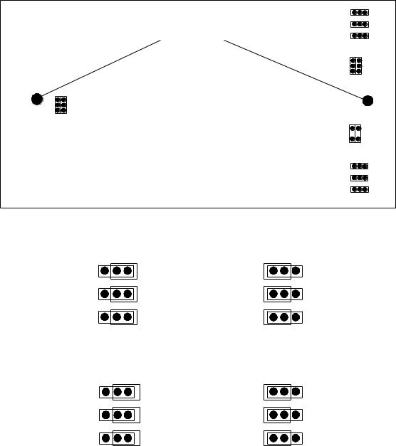
Figure 6 – Jumper settings
|
J104 |
|
|
J105 |
|
Mounting screws |
J106 |
|
|
|
|
|
J102 |
J101 |
J1J2
J202 
 J201
J201
J204
J205
J206
Left Channel
Left Channel
J104
J105
J106
J204
J205
J206
Left Channel
Left Channel
J104
J105
J106
J204
J205
J206
Jumper setting |
Jumper setting |
for MM |
for MC |

THANK YOU FROM EVERYONE AT CLASSÉ
Thank you for purchasing the Classé CP-35 preamplifier.
We take great pride in offering components that combine exceptional sonic performance and
long-term reliability. To do that, we have invested in extraordinary design and manufacturing facilities. We trust that you will enjoy your purchase for many years to come.
CLASSÉ DESIGN PHILOSOPHY
All of our components benefit from the same rigorous design goal: All Classé products must reproduce music with the harmonic and spatial integrity typical of fine instruments heard in a live, unamplified performance.
Single Circuit Design
To this end, we make extensive use of carefully optimized versions of the same basic circuit precisely matched to specific power requirements. This means that all Classé line level components and power amplifiers benefit from years of refinement. However, our efforts do not stop here.
Listening: The Critical Design Element
Once we determine general circuit values
for a particular application, we listen carefully while exchanging and mixing different parts (transistors, capacitors, wiring, PC boards, etc.) and adjusting specific operating voltages within proper engineering ranges.
Extended Real-World Lifespan
Every Classé component, even the most affordable, benefits from our painstaking approach to design parameters. The result is an optimum balance between the often-conflicting demands of exceptional performance and longterm reliability. Our most expensive components gain from even tighter tolerance parts and highly segmented and exceptionally robust power supplies with large reserve-current capabilities.
Our Pride in Manufacturing, Your Pride in Ownership.
We build all of our components to the highest possible standards. From multi-layer glass-epoxy circuit boards, the full sized power-supplies, and the massive faceplates, every Classé product is a tribute to both the science and art of sound reproduction. We hope that you derive as much pleasure and satisfaction in using your Classé as we did in producing it.
UNPACKING & SET-UP
Your CLASSÉ CP-35 preamplifier has been carefully wrapped in heavy gauge plastic, packed in semi-rigid foam and contained in a special box. To remove the unit, open and spread the top flaps of the box. By its sides, lift out the entire unit with foam pieces intact. Remove each foam side by pulling straight out. Remove the plastic wrap and inspect the unit for any concealed damage. Apart from this owner's manual, please ensure the follow-ing has also been included:
•DETACHABLE LINECORD.
•REMOTE CONTROL UNIT (AAA x 2 included).
Please report any damage or missing parts to your dealer promptly.
This preamplifier, being capable of very high gain, must be located in a position free of any hum-inducing magnetic fields. (This also applies to turntables and interconnect cables.) Positions adjacent to power amplifiers, A.C line filters, or regulation devices should be avoided. Ideally, a few feet should separate the preamplifier from the power amplifier. As well, keep low-level interconnect cables away from the power amp and separate from A.C. linecords.
Heat generated by the preamplifier is negligible. Air space around the unit need not be a concern.
Check the Serial Number sticker on the back of the unit for the correct operating voltage. Regardless of voltage, the internal fuse rating should be 1 AMP SLO-BLO.
A.C. LINE POWER
The Classé CP-35 preamplifier has no power switch. Its low power consumption and improved sonics from always being ON led to the omission of an ON/OFF switch. In fact, while thoroughly musical shortly after turn-on, the preamplifier will exhibit “sonic growth” during its first 300 hours of use.
For optimum sonic performance, you should consider the use of the optional CLASSÉ REFERENCE A.C. LINECORD. Consult your dealer regarding this accessory.
Safety Feature:
The CP-35 preamplifier is designed with an auto-muting circuit which engages during the initial 20 seconds count down and is indicated by MUTE at the right of the display when the unit is first connected, or after an AC power failure. After the 20 seconds countdown, the MUTE signal at the right of the display will be ON thus showing that the unit is in MUTE mode.
This feature will prevent any turn-on surges or unstable output from reaching the power
amplifier and possibly the loudspeakers. Similarly, make sure the MUTE is ON again when removing A.C. line power.
CAUTION: Disconnect AC line cable while making all connections. “Floating the ground”, or defeating the ground on a 3-prong linecord may create a shock hazard. Connect all interconnect cables between the electronics before connecting the A.C. linecords to the wall outlets. This will reduce the potential shock hazard. See also the warranty section of this owner's manual.
INPUTS
The input jacks are clearly marked on the back of the CP-35. The following inputs are provided: LINE 1, LINE 2, LINE 3, LINE 4, BAL 1 and TAPE (see fig. 3).
LINE LEVEL INPUTS LINE 1, LINE 2, LINE 3 , and LINE4: These are all high level inputs sharing exactly the same characteristics, and may be interchanged if so desired. A tape machine should only be connected to the TAPE input. See TAPE IN and TAPE OUT below. The LINE 1 input could also be fitted with an OPTIONAL PHONO BOARD plug in module installed in the unit. A ground screw is provided adjacent to the LINE 1 input jack.
Installation of the Phono Board
•Disconnect the A.C. line cord from the wall outlet.
•Remove the top cover with the supplied Allen key.
•Locate and replace the two mounting screws (see Fig.5) with the supplied stand-offs.
•Remove jumpers J5, J6, J13 and J14
(see fig. 5). Check if extension sockets are in place on the reverse side of the phono board.
•Install and secure the phono board using the screws removed previously in step 3, make sure all the connectors are properly aligned.
•Set MM/MC (see fig.6) jumpers to the desired position. All six of these jumpers are located at the far right of the phono board (see fig.5). Please note that for ALL HIGH OUTPUT MC cartridges, the jumpers have to be SET AT MM.
•Replace the top cover.
Removal of the Phono Board
•Disconnect the line cord from the wall outlet.
•Remove the top cover with the supplied Allen key.
•Remove the screws securing the phono board, remove the phono board and the stand-offs, replace the screws where the stand-offs were removed (see fig. 5) to secure the main board.
•Replace jumpers J5, J6, J13 and J14 (see fig. 5) on the main board. Jumpers from the phono board can be used for that purpose.
•Replace the top cover.
BALANCED INPUT BAL 1:
The BALANCED INPUT is a true differential high level input, wired as follows:
•PIN 1: GROUND
•PIN 2: POSITIVE (NON-INVERTED) SIGNAL
•PIN 3: NEGATIVE (INVERTED) SIGNAL
1

It may be used with CD players that have a BALANCED output, or any other high level BALANCED sources.
Tape In
The TAPE IN of the CP-35 preamplifier should be connected to the LINE OUT or TAPE OUT of the tape deck. The TAPE input does not appear on the selector switch. It is activated by the TAPE switch. (See FRONT PANEL CONTROLS: TAPE BUTTON.)
IR In (and Out)
This will permit you to install an outboard infra-red sensor and therefore be able to control the CP-35 remotely from another room where the outboard IR sensor has been installed. These connections will be found below the AC power inlet at the back of the unit (see fig.3).
OUTPUTS
The Classé CP-35 preamplifier has both line level (single-ended) and BALANCED outputs (see fig. 3). Both are working at all times, and may be used separately, or simultaneously.
Tape Output
Whatever input is selected by the INPUT SELECTOR will be fed to the TAPE OUTPUT jacks. This should be connected to the TAPE IN or LINE IN of the tape deck.
Line Level Outputs
Simply connect your LINE LEVEL interconnects to the RCA output jacks marks LINE LEVEL OUTPUT on the back of the CP-35.
Balanced Outputs
A BALANCED power amplifier and BALANCED interconnects are also required. For use with a BALANCED power amplifier other than Classé, the wiring of the 3-pin XLR connectors must be wired as follows:
•PIN 1: GROUND
•PIN 2: POSITIVE (NON-INVERTED) SIGNAL
•PIN 3: NEGATIVE (INVERTED) SIGNAL
If the pin configuration of the power amplifier differs from above, the BALANCED interconnects must be modified to accommodate the different power amp.
Having confirmed the correct connections, plug the XLR connectors of the BALANCED interconnects into the locking XLR connector on the rear of the CP-35 marked BALANCED OUTPUT. (To remove the connectors, press the tab above the connector.)
FRONT PANEL CONTROLS
Input Selector:
The input selector (see fig.4) has two buttons for selecting the inputs; (<) and (>). Pressing the
< button. selects the input to the left of the currently selected input, and pressing the > button selects the input to the right of the
currently selected input. If the > button is pressed when BAL1 is the current input then the LINE1 input will be selected, and if the < button when LINE1 is the current input then the BAL1 input will be selected. The < and > buttons
will select from five input connections on the preamplifier, but not the TAPE, (see TAPE below).
Tape
In the SOURCE position (TAPE LED OFF), the preamp will process the signal as chosen by the INPUT SELECTOR. In the TAPE position (TAPE LED ON (RED)), the preamp will process the TAPE INPUT signal, overriding the INPUT SELECTOR.
Volume Control
The VOLUME CONTROL varies the output level of both channels simultaneously. It can be operated by remote using the hand held control unit (see fig.4) or manually turning the control knob at the preamp. The volume control has a total of
120 steps of level adjustments form 0 to 60 in 0.5 stepped increments. When the unit is plugged in, the display will count down from
20 to 0. When the countdown has resumed, the volume will be automatically at zero (0) and the preamp will be muted and therefore show MUTE at the right of the digit display. When you unmute, the volume will return to the same level
it was at before you turned on the mute mode. PLEASE NOTE: It is normal for the volume to stay at the same level if you turn the VOLUME knob extremely slowly.
Mute
Press the MUTE button (see fig. 4) to temporarily set the VOLUME to 0. When activating the MUTE function , MUTE will light up at the right of the volume display digits. Switching can be done by either pushing the MUTE button momentarily on the CP-35 faceplate or on the remote handset. The volume setting is memorised when the
unit is in mute mode; thus Volume will return to the same level it was playing at prior to muting when you turned off MUTE mode. (see DISPLAY section)
PLEASE NOTE: The display will change to Display Full Off mode after the unit has been in MUTE mode for one hour.
NOTE: When the CP-35 is in the mute position, and the volume control is turned up using the volume control on the unit or the remote control, the play mode is automatically selected.
CAUTION: Make sure the preamp is in MUTE(ON) when making or changing any connections. This includes all inputs and outputs, as well as A.C. linecord.
Remote Handset
The remote handset will permit you to access remotely all the functions found on the front panel of the unit: VOLUME UP or DOWN, MUTE ON or OFF, DIRECT ACCESS for all the INPUTS and TAPE monitor. In addition to all these functions, the button marked DISPLAY will permit you to select through the four display modes on the unit.
PLEASE NOTE that the DISPLAY function can only be activated through the remote handset.
To access the batteries, unscrew the back plate of the remote handset (see fig. 2)
Balance Control (on Remote Handset only):
The balance control found on the remote handset only permits equal output of each channel in the center (00.0) position without additional loading to the signal. When shifted to the left or right, it merely attenuates the opposite channel. When operating the balance control, the right of the display will show BALANCE. By shifting the balance to either sides (left or right) one of the two LEDs located on either sides of the DIGIT display will light accordingly to the side on which the balance is shifted. The amount of attenuation will be show on the DIGIT display in increments of 0.5 up to19.5. If the balance control if shifted to the
maximum (19.5) on either sides, the digit display will show OFF which means that the opposite channel now gives out no signal since the balance is completely shifted to one side.
Display (on Remote Handset only)
Pressing the DISPLAY button on the remote handset (see fig. 1) allows you to control the brightness of the display. There are 3 levels of brightness; Display On, Display Medium On, Display Low On or Display Full Off. Repeated pressing of the DISPLAY button will cycle through the four modes, from Display Full On to Display Full Off. Pressing DISPLAY when the display is
at Full Off will cause the display to go back to Display Full On.
NOTE: Three (3) LEDs will continue to be lit on the display when it is in Display Full Off mode to let you know that the CP-35 is still on and operating. When in Display Full Off mode and any other functions are used, such as changing
volume or selecting a new source, the display will light at Display Full On mode for five seconds and then go back to Display Full Off mode. The display will automatically go to Display Full Off mode after the MUTE mode has been activated for one hour.
CP-35 FEATURES:
Remote control featuring adjustments for volume, direct access input selection, tape, display and mute. Contoured slimline chassis. Inputs featuring LINE1, LINE2, LINE3, LINE4 and BAL1 inputs. Both BALANCED and LINE LEVEL outputs. Front panel adjustments include input selection, volume and mute. Special Classé front panel in Soft Shadow Silver with Satin Black display panel plate.
Notice to all Classé Product owners:
Thank you for your purchase of a Classé Audio component.
All of us at Classé have taken extreme care to ensure that your purchase will become a prized investment. We are proud to inform you that all Classé Audio components have been officially
2

approved for the European Community CE mark. This means that your Classé product has been subjected to the most rigorous manufacturing and safety tests in the world, and have proven to meet or exceed all European Community CE requirements for unit to unit consistency and consumer safety.
All of us at Classé Audio wish you many years of musical enjoyment.
As of July 18, 1996, Classé Audio has been granted Certificate No: C401CLA1.MGS, which indicates CE approval for all models of the Classé Audio product line.
CLASSÉ AUDIO
5070 François Cusson
Lachine, Quebec
Canada H8T 1B3
Telephone: + 1 (514) 636-6385
Fax: + 1 (514) 636-1428
FRANÇAIS
TOUTE L’ÉQUIPE DE CLASSÉ VOUS REMERCIE !
Nous vous remercions pour l’achat de ce préamplificateur intégré Classé CP-35.
Nous prenons un soin jaloux à concevoir et proposer des maillons qui associent une musicalité exceptionnelle avec une fiabilité hors pair. Pour cela, nous avons choisi un dessin très original pour nos appareils, et l’avons équipé de nombreuses fonctions particulièrement ergonomiques. Nous sommes ainsi certains que vous profiterez de votre achat pendant de très nombreuses années.
PHILOSOPHIE DE CONCEPTION CLASSÉ
Tous nos maillons sont conçus dans le même souci de perfection et de rigueur : les appareils Classé doivent reproduire intégralement la Musique, avec tous ses harmoniques, et le respect total de la position et de l’ampleur des instruments dans l’espace. Exactement comme dans une écoute en direct, sans amplification électronique aucune.
Un circuit électronique unique
Pour cela, nous utilisons principalement un circuit électronique de conception unique, reprenant sur tous nos maillons les mêmes principes de base adaptés aux demandes en puissance de chaque appareil. C’est ainsi que tous les préamplificateurs Ligne et amplificateurs de puissance Classé bénéficient depuis des années de la même qualité sonore. Cependant, nos efforts ne s’arrêtent pas là.
L’écoute : l’élément le plus critique pendant la conception
Une fois que nous avons déterminé les valeurs précises de chaque circuit électronique, en fonction de chaque application particulière, nous procédons à de très nombreuses écoutes attentives en modifiant et en associant certains composants (transistors, condensateurs, câblage, cartes circuits imprimés, etc.). Puis nous réglons très précisément les différentes tensions nécessaires au parfait fonctionnement de ces composants.
Une durée de vie exceptionnelle
Chaque maillon Classé, même le plus abordable, bénéficie de cette très soigneuse approche dans la conception. Le résultat est un équilibre parfait entre les demandes souvent opposées que représentent une musicalité exceptionnelle et une fiabilité à toute épreuve. Dans ces deux domaines, les gains sont obtenus par l’utilisation de composants aux tolérances très strictes, avec une implantation large et soignée, et l’emploi d’alimentations exceptionnellement robustes, disposant toujours de très grandes réserves de courant.
Notre fierté est dans la fabrication. La vôtre est dans la possession.
Nous construisons donc tous nos maillons selon les standards en vigueur les plus élevés. Qu’il s’agisse des circuits imprimés multicouches en verre époxy, des alimentations surdimensionnées, ou des très épaisses faces avant des appareils, chaque appareil Classé devient une référence dans l’art de maîtriser à la fois la technique électronique et celui de la reproduction sonore et musicale. Nous espérons que vous tirerez autant de plaisir et de satisfaction à utiliser votre nouveau Classé que nous en avons eu à le concevoir et à le fabriquer.
DÉBALLAGE & MISE EN SERVICE
Votre PRÉAMPLIFICATEUR INTÉGRÉ CLASSÉ CP-35 est emballé dans une feuille de plastique épais, puis inséré dans une coquille moulée semi-rigide, placée dans un carton spécial. Pour sortir l’appareil, ouvrez et repliez tous les rabats supérieurs du carton, tirez l’ensemble appareil plus protection interne et posez-le sur une surface plane. Ôtez le sac plastique de protection et inspectez soigneusement l’appareil pour repérer tout dommage éventuel. En plus de ce manuel d’utilisation, vous trouverez également dans l’emballage :
•CÂBLE SECTEUR DÉTACHABLE
•TÉLÉCOMMANDE (Piles : 2 x AAA fournies)
Veuillez avertir immédiatement votre revendeur de toute détérioration constatée sur l’appareil, ou accessoire manquant.
Ce préamplificateur CP-35, fournissant un gain particulièrement élevé, doit être positionné à un endroit exempt de tout champ magnétique externe (ce qui est également valable pour les platines tourne-disque et tous les câbles de liaison modulation). On évitera également de le placer tout près des amplificateurs de puissance, filtres secteur, ou coffrets de régulation. Idéalement, on conservera une distance de quelques centimètres vis-à-vis des autres maillons de l’installation. De même, les câbles de liaison modulation seront soigneusement séparés des câbles d’alimentation secteur.
La chaleur dégagée par ce préamplificateur est négligeable. Inutile de prévoir une circulation d’air spécial autour de son coffret.
Vérifiez l’étiquette en face arrière pour la tension de fonctionnement secteur du préamplificateur. Quelle que soit cette tension, le fusible de protection interne est de type 1 ampère, à fusion retardée.
ALIMENTATION SECTEUR
Le préamplificateur CP-35 ne possède pas d’interrupteur de mise sous tension. Cette absence s’explique par la très faible consommation de l’appareil, et les meilleures performances sonores obtenues lorsque le préamplificateur reste en permanence sous
3
 Loading...