


FOLDING CRANE
MODEL NO: CFC2000B
PART NO: 7611025
ASSEMBLY & USER INSTRUCTIONS
ORIGINAL INSTRU CTIONS GC0318 ISS2

INTRODUCTION
Thank you for purchasing this CLARKE Folding Crane.
Before attempting to operate the product, it is essential that you read this
manual thoroughly and carefully follow all instructions given. In doing so you
will ensure the safety of yourself and that of others around you, and you can
also look forward to the stand giving you long and satisfactory service.
TECHNICAL SPECIFICATIONS
Max Capacity (SWL) 2000 kg (2 Tonne)
Net Weight 99 kg
Dimensions (Folded Position) L x D x H
Dimensions (Unfolded Position) L x D x H
Number of pump actions from rest to max height 69
Ram Oil Capacity 0.8L
Oil Grade ISO VG15
Jib Positions Position 1
Lift Capacity 500 kg (0.5 Tonne)
Jib Length Horizontal 1600 mm
Max Lifting Height 2660 mm
Position 2
Lift Capacity 1000 kg (1 Tonne)
Jib Length Horizontal 1420 mm
Max Lifting Height 2530 mm
Position 3
Lift Capacity 1500 kg (1.5 Tonne)
Jib Length Horizontal 1240 mm
Max Lifting Height 2380 mm
Position 4
Lift Capacity 2000 kg (2 Tonne)
Jib Length Horizontal 1060 mm
Max Lifting Height 2280 mm
850 x 690 x 1620 mm
1070 x 1760 x 1415 mm
2
Parts & Service: 020 8988 7400 / E-mail: Parts@clarkeinternational.com or Service@clarkeinternational.com

SAFETY PRECAUTIONS
1. Always read instructions before setting up the equipment and before use.
Failure to heed these warnings may result in damage to the equipment, or
serious personal injury.
WORKPL ACE SAF ETY
1. Always inspect the crane before use to ensure it is correctly assembled and
in good condition and replace any damaged or worn parts.
2. Only use the crane on a flat, solid, level surface that is capable of bearing
the weight of the loaded crane, preferably concrete. Never work on soft/
unmade ground as the castors may sink in.
3. Ensure the crane operator is trained in both operation and safety aspects.
4. Do not allow personnel to use the crane unless they have read these safety
precautions.
5. Use the crane in a suitable, well lit work area.which is clean and tidy and
free from unrelated items.
6. Do not use the crane when you are tired or under the influence of alcohol,
drugs or intoxicating medication.
7. Ensure all bystanders keep at a safe distance whilst the crane is in use.
8. Do not over-reach. Keep your proper footing and balance at all times.
9. Safety equipment such as gloves and non-skid safety shoes will reduce
personal injuries.
INSPECTION BEFORE USE
1. Always visually inspect the crane before use, to ensure that all parts are
correctly located and secure. Check for cracks, deformation or other signs
of damage or worn parts and check the castors for damage. Do not use
the crane unless it is totally sound.
2. Check castors to ensure they move freely without undue wear to their
pivots, and that the wheels are not cracked or damaged.
SAFE OPERATING PRACTICE
1. Only use chains, slings, hooks etc. with a rated capacity equal to, or
greater than that of the load. Check that they are secure and will not slip
under load.
2. Never exceed the safe working load capacities specified on the jib for
each position (as marked on the jib).
3
Parts & Service: 020 8988 7400 / E-mail: Parts@clarkeinternational.com or Service@clarkeinternational.com

3. Always fully lock the jib and legs into position before lifting.
4. Lower the load as much as possible before moving the crane. Do not use
the crane to transport loads over long distances.
5. Do not allow the load to swing or drop suddenly whilst moving or lowering.
6. Do not use this crane to lift people.
7. Do not work under any raised load.
8. Never climb on, or attempt to ride on the crane.
9. Take care not to trap your fingers in the adjustable parts of the crane.
10. Due to the weight of the loaded crane, the help of an assistant will be
beneficial when moving the crane around.
11. This is a heavy item (99kg). Take care when moving or folding away.
12. Never attempt to move a loaded crane across a floor having cracks,
pebbles, or other obstacles which might impede its movement.
13. To move a loaded crane, push it from the operators side. DO NOT move
the crane from the handle end and never pull the crane towards yourself.
CARE OF THE CRANE
1. Ensure that the crane is properly maintained at all times, and that no
corrosion is allowed to weaken any components.
2. When replacing parts, use only those supplied by Clarke International.
Refer to Parts List on pages 14-15.
3. If the crane has been subjected to an abnormal load or shock, it should be
removed from service immediately and fully inspected by qualified
personnel.
4. Never tamper with the crane or modify it in any way, as this could prove to
be dangerous and will invalidate the guarantee. Only use the crane for the
purpose for which it is intended.
5. The components of this crane are designed to withstand the rated
capacity. Do not substitute any other components or exceed the rated
capacity of the crane.
6. If the load capacity decal becomes worn or illegible, contact Clarke Parts
and service department, on 0208 988 7400 for replacement.
4
Parts & Service: 020 8988 7400 / E-mail: Parts@clarkeinternational.com or Service@clarkeinternational.com

UNPACKING & ASSEMBLY
Unpack the components on a clean flat area of hard standing and ensure
that all parts are present according to the packing list, as follows:
1 2 x Side Braces 9 1 x Control handle
2 1 x Handle 10 1 x Main Support Post
3 1 x Jib 11 2 x Front Legs
4 2 x Side Plates 12 1 x Base Frame
5 1 x Hydraulic Ram Assembly 13 2 x Locking Pins
6 1 x Jib Extension 14 Small fixings pack
7 1 x Hook 15 Large fixing bolts, nuts & washers
8 6 x Castor Assemblies( 2 with
brakes
Visually inspect all components to ensure that no damage was suffered in
transit. Any deficiencies should be reported to your CLARKE dealer
immediately.
5
Parts & Service: 020 8988 7400 / E-mail: Parts@clarkeinternational.com or Service@clarkeinternational.com

ASSEMBLY
TOOLS REQUIRED
Various wrenches of 14, 22, 24 & 27 mm will be required or alternatively an
adjustable wrench.
1. Fit the castors to the front arms
using 4 x bolts, lock washers and
nuts. Loosely fasten the rear 2
bolts & nuts through the slots
before sliding the caster into
position and adding the other two
bolts.
2. Repeat for both castors.
3. Bolt the four remaining castors to
the base frame.
• The castors fixed to the open
section of the base frame are
fixed with bolts threaded into
the frame no nuts are used.
4. Bolt the side brackets to each side
of the base frame with a single
small bolt.
• The 130 mm bolts will be added
at the next step.
6
Parts & Service: 020 8988 7400 / E-mail: Parts@clarkeinternational.com or Service@clarkeinternational.com

5. Slide the right arm into the base
frame as shown. Line up the holes
and secure with a 130 mm bolt,
washers and nut, securing the side
bracket as you do so.
6. Repeat the procedure for the left
arm.
7. Insert the locking pins and secure
the pins using the R-clips attached
to the small chains.
WARNING: IT IS ESSENTIAL THAT THE LOCKING PINS ARE IN PLACE BEFORE
ATTEMPTING ANY LIFTING TASKS. FAILURE TO INSTALL THESE WOULD
RESULT IN THE CRANE TIPPING FORWARD WHEN SUBJECTED TO ANY
LOAD.
8. Attach the main support post
onto the base frame assembly
using two 110 mm long bolts with
washers and nuts. Leave the nuts
& bolts loose until step 9.
9. Add the two side braces, bolting
them between the base frame
and the main support post. Leave
the bolts loose until they are
aligned with the hole in the main
support post. Once aligned, fully
tighten the side braces to the
base and the support post.
7
Parts & Service: 020 8988 7400 / E-mail: Parts@clarkeinternational.com or Service@clarkeinternational.com

10. Fix the ram to the main support
post using 90 mm long bolt,
washer and nut.
11. Attach the jib to the top of the
main support post using the 90
mm bolt, washer and nut.
12. Connect the top of the ram to the
jib as shown using 80 mm long
bolt, washer and nut.
NOTE: The ram may require partially
extending to facilitate
assembly.
13. Slide the jib extension into the jib,
using the 100 mm long locating
bolt and nut to secure it in the
required position.
14. Bolt the hook assembly through
the hole on the jib extension using
the 80 mm bolt, washer, lock
washer and nut.
8
Parts & Service: 020 8988 7400 / E-mail: Parts@clarkeinternational.com or Service@clarkeinternational.com

15. Connect the handle to the rear of
the main support post using the
four remaining small bolts and
lock washers.
16. Ensure that all weight is spread
evenly across all sections, making
sure that all castors are on level
ground and that the assembly is
sitting square and true. Tighten all
nuts and bolts.
17. Store the operating handle in the
holder on the column.
OPERATION
WARNING: IT IS ESSENTIAL THAT THE FRONT ARM LOCKING PINS ARE IN
PLACE BEFORE ATTEMPTING ANY LIFTING TASKS. FAILURE TO INSTALL
THESE WOULD RESULT IN THE CRANE TIPPING FORWARD WHEN SUBJECTED
TO ANY LOAD.
RAISING THE JIB
IMPORTANT: Make sure that the hook is directly above the point of lift, which
in turn is directly above the centre of gravity of the load.
1. Use the end of the pump handle
to close the valve by turning it fully
clockwise.
• It should only be hand tight, -
do not overtighten.
2. Pump the handle until the crane
reaches the desired height.
9
Parts & Service: 020 8988 7400 / E-mail: Parts@clarkeinternational.com or Service@clarkeinternational.com

LOWERING THE JIB
1. Use the end of the pump handle to turn the valve anticlockwise VERY
SLOWLY.
• The speed of lowering is controlled by how much you turn the valve.
EXTENDING THE JIB
1. Lift the jib to a horizontal position.
2. Remove the locating bolt.
3. Reposition the jib extension to the
desired length.
• The hole near the end of the jib
extension will match the hole in
the jib according to the weight
being lifted. These are clearly
marked.
4. Replace the locating bolt, nut and washer.
5. Store the operating handle in the socket provided when not in use.
PURGING THE HYDRAULIC SYSTEM
During transit or storage, it is possible that an air pocket may have developed
within the hydraulic ram and the ram action may therefore appear to be
‘spongy’. As the ram is self bleeding, any air will be dispelled and the ram
action normalised by fully raising and lowering the jib a few times.
Should the jib not reach its full height, the oil level should be checked, as
described in the Maintenance section.
STORAGE
1. Remove the bolt and slide the jib
extension back to its shortest
position. Replace the bolt to
secure the jib.
2. Release the control valve to lower
the jib assembly to its lowest
position.
3. Pull out the ‘R’ clip, which secures
the each leg locking pin, then pull
out the lock pin.
10
Parts & Service: 020 8988 7400 / E-mail: Parts@clarkeinternational.com or Service@clarkeinternational.com

4. Raise the leg up to its storage
position.
5. Replace the leg locking pin
through the hole in the frame so
that the leg is locked in the up
position.
6. Replace the retaining clip to
secure the leg locking pin.
7. Store the pump handle in its
bracket on the side of the main
support post.
8. Once the crane is folded use
extreme care when moving it to
the storage location.
STORAGE WARNING
1. The crane MUST be firmly secured
to a wall or fixed location when
not in use.
2. Use a strong strap or chain or
suitable restraint to prevent any
accidental movement.
3. Test that the crane is firmly secured before leaving it in its storage location.
MAINTENANCE
GENERAL
1. Always store the crane with the jib in its lowest position, This prevents any
possibility of corrosion to the ram.
2. Do not leave the crane in the open or exposed to the elements. Keep
under cover.
3. Do not attempt to adjust or tamper with the ram assembly, there are no
user-serviceable parts. Contact your Clarke service department for any
servicing.
4. Always visually inspect the crane before use, to ensure that all parts are
correctly located and secure. Check for hydraulic leaks, signs of damage
or worn parts and check the wheels and castors for serviceability.
11
Parts & Service: 020 8988 7400 / E-mail: Parts@clarkeinternational.com or Service@clarkeinternational.com
ANNUALLY
1. The crane should be fully inspected annually by a competent person.
2. Each load bearing bolt should be removed and inspected for wear,
deformation or cracks. If any are apparent, the bolt should be renewed.
3. Check the hydraulic ram operation and inspect for oil leaks. A slight
dampness on the ram is normal, but where leakage is apparent, the ram
seals must eventually be renewed and the lost oil be replaced. Consult
your Clarke service department.
4. Check castors to ensure they move freely without undue wear to their
spindles, and that the wheels are not cracked or damaged.
5. Remove any rust and repaint to prevent further corrosion.
6. Ensure that all decals and warning labels are in place and clearly legible.
HYDRAULIC OIL
If any leakage is observed, it may be necessary to top up the hydraulic oil
level, as follows.
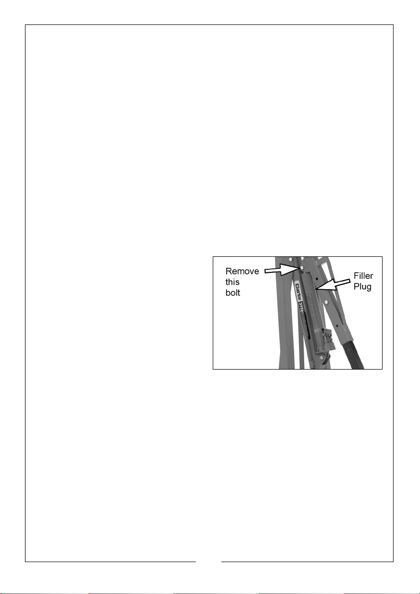
1. Lower the jib to its lowest position,
and remove the bolt that joins the
ram to the jib. This will allow the
ram to fully retract.
2. Rest the ram against the main
support post and raise and prop
up the jib. Use a cable or similar, to
ensure the ram does not move.
3. Remove the filler plug from the
side of the ram.
4. Top up the oil until it is level with the hole and replace the filler plug.
NOTE: Top up using Clarke hydraulic oil (part number 3050830).
• Do not mix different types of oil.
12
Parts & Service: 020 8988 7400 / E-mail: Parts@clarkeinternational.com or Service@clarkeinternational.com

DECLARATION OF CONFORMITY
13
Parts & Service: 020 8988 7400 / E-mail: Parts@clarkeinternational.com or Service@clarkeinternational.com

PARTS DIAGRAM
14
Parts & Service: 020 8988 7400 / E-mail: Parts@clarkeinternational.com or Service@clarkeinternational.com

PARTS LIST
PART NO DESCRIPTION PART NO DESCRIPTION
1 Bolts, nuts & washers 19 Hex Head Bolt M14 x 110
2 Front Leg 20 Hex Head Bolt M16 x 90
3 Swivel Castor (3”) 21 Main Support Post
4 Hex Head Bolt M8 x 12 22 Washer M16
5 Spring Washer M8 23 Pump Handle
6 Base Frame 24 Hydraulic Ram Assembly
7 Nut M14 25 Hex Head Bolt M16 x 100
8 Washer M14 26 Handle
9 Retaining Clip 27 Hex Head Bolt M16 x 110
10 Locking Pin 18x125 28 Washer M18
11 Hex Head Bolt M18 x 130 29 Hex Head Bolt M16 x 80
12 Side Bracket 30 Jib
13 Spring Washer M18 31 Hex Head Bolt M16 x 100
14 Nut M18 32 Jib Extension
15 Hex Head Bolt M16 x 130 33 Hex Head Bolt M14 x 80
16 Side brace 34 Hook Assembly
17 Spring washer M16 35 Braked Swivel Castor
18 Nut M16 36 Securing Ring
GUARANTEE
This CLARKE product is guaranteed against faulty manufacture for a period of
12 months from the date of purchase. Please keep your receipt as proof of
purchase.
This guarantee is invalid if the product is found to have been abused or
tampered with in any way, or not used for the purpose for which it was
intended.
Faulty goods should be returned to their place of purchase, no product can
be returned to us without prior permission. This guarantee does not effect your
statutory rights.
15
Parts & Service: 020 8988 7400 / E-mail: Parts@clarkeinternational.com or Service@clarkeinternational.com

 Loading...