

Page 1
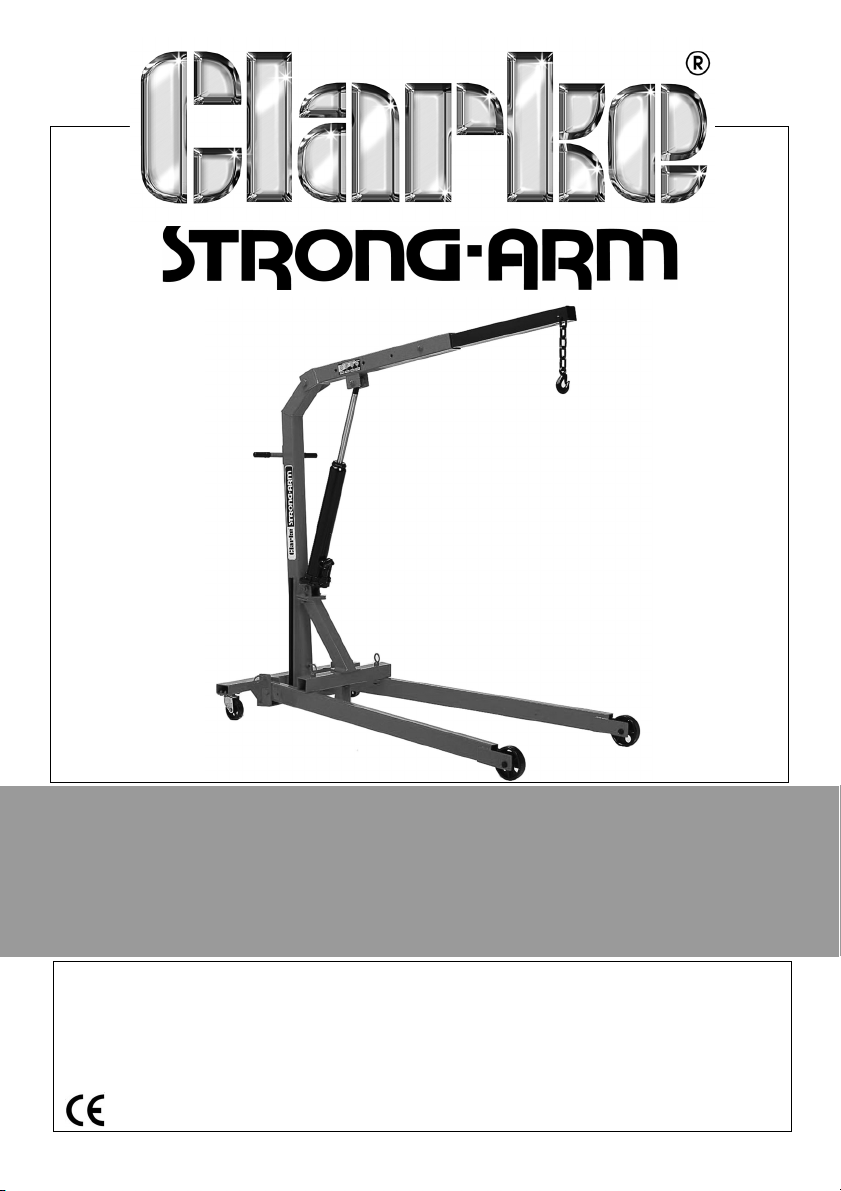
1/2 TON CRANE
MODEL NO: CFC500F
PART NO: 7610610
OPERATING & MAINTENANCE
INSTRUCTIONS
GC12/13
Page 2
INTRODUCTION
Thank you for purchasing this CLARKE Hydraulic Crane.
Before attempting to use this product, please read this manual thoroughly and
follow the instructions carefully. In doing so you will ensure the safety of yourself
and that of others around you, and you can look forward to your purchase
giving you long and satisfactory service.
GUARANTEE
This product is guaranteed against faulty manufacture for a period of 12
months from the date of purchase. Please keep your receipt which will be
required as proof of purchase.
This guarantee is invalid if the product is found to have been abused or
tampered with in any way, or not used for the purpose for which it was
intended.
Faulty goods should be returned to their place of purchase, no product can
be returned to us without prior permission. This guarantee does not effect your
statutory rights.
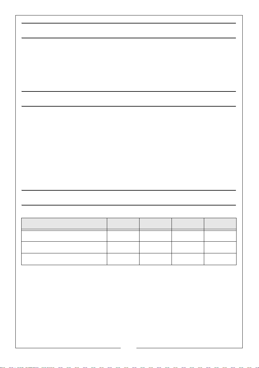
SPECIFICATION
Stage 1 Stage 2 Stage 3 Stage 4
Lifting Capacity (kg) 500 350 250 150
Max Lift Height (mm) 1890 2110 2240 2360
Min. Lift Height (mm) 435 280 115 0
Overall Width (mm) 850
Height of Legs (mm) 140
Weight (kgs) 88.5
Please note that the details and specifications contained herein are correct
at the time of going to print. However Clarke International reserve the right to
change specifications at any time without prior notice.
2
Parts & Service: 020 8988 7400 / E-mail: [email protected] or [email protected]
Page 3
GENERAL SAFETY RULES
WARNING: FAILURE TO FOLLOW THESE PRECAUTIONS COULD RESULT IN
PERSONAL INJURY, AND/OR DAMAGE TO PROPERTY.
1. Always read instructions before setting up the equipment and before use.
2. Always inspect the crane before use to ensure it is correctly assembled and
in good condition, and replace any damaged or worn parts.
3. When replacing parts, use only those supplied by Clarke International.
4. Never exceed the safe working load capacities specified on the jib for
each position (as marked on the jib).
IMPORTANT: If the load capacity label becomes worn or illegible, contact
Clarke Parts and service department, on 0208 988 7400 for a replacement.
5. Only use chains, slings, hooks etc. with a rated capacity equal to, or
greater than that of the load. Check that they are secure and will not slip
under load.
6. Only use the crane on a flat, solid, level surface that is capable of bearing
the weight of the load.
7. Lower the load as much as possible before moving the crane. Do not use
the crane to transport loads.
8. Use appropriate safety equipment, such as protective footwear, when
using this crane.
9. Ensure the crane operator is trained in both operation and safety aspects.
10. Do not allow the load to swing or drop suddenly.
11. If the crane has been subjected to an abnormal load or shock, it should be
removed from service immediately and fully inspected by qualified
personnel.
12. Ensure that the crane is properly maintained and lubricated at all times,
and that corrosion is not allowed to weaken any component.
13. Do not use around children or untrained persons.
14. This is a heavy item. Take care when moving.
15. Do not use this crane to lift people.
16. Do not work under any suspended load.
3
Parts & Service: 020 8988 7400 / E-mail: [email protected] or [email protected]
Page 4

ASSEMBLY
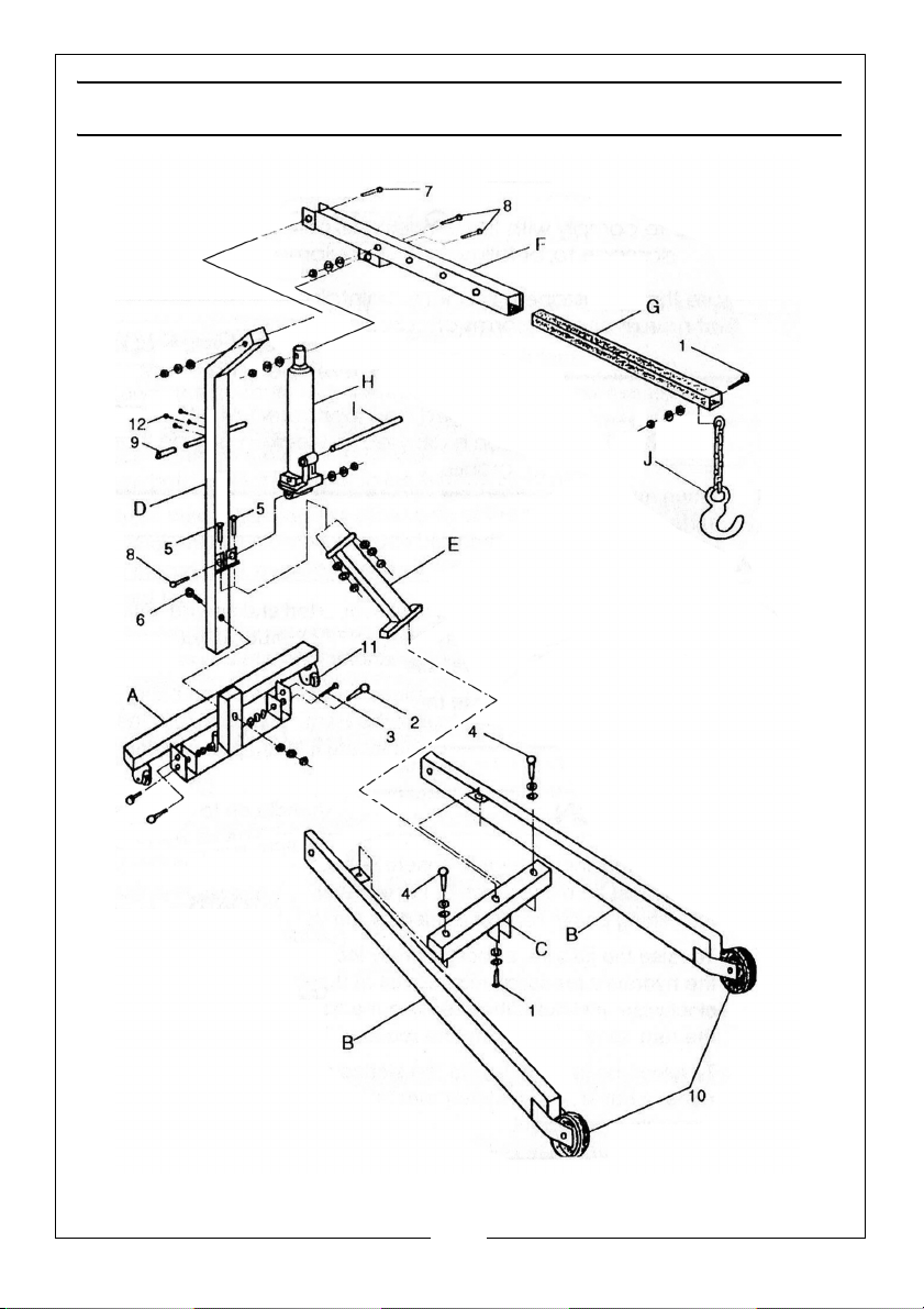
Using a clean, level area, unpack, check and identify all the components
including nuts, bolts and washers and lay out the main components in relation
to the parts diagram on page 10. During assembly, nuts and bolts should only
be finger tightened prior to final tightening upon completion.
1. Locate each front leg (B) into its recess on the rear support (A), ensuring
the brackets for the extension support (C), are uppermost and facing
inwards. Line up the holes and secure using fixings (3).
2. Place the extension support (C) on the brackets on top of the front legs (B),
ensuring that the channel section, welded to the centre of the extension
support, is in a downwards position, with the open end facing towards the
front leg wheels. Secure using eyebolts (4).
3. Lower the main support post (D) onto its mounting on the rear support and
bolt in place.
4. Place the support bracket (E) over the hole provided in the centre of the
extension support (C), and locate from underneath with a single bolt (7).
• The upper end of the support bracket is now mated with the bracket
on the main support post and fixed in position with the bolts (5).
5. All nuts and bolt assembled so far can now be tightened.
6. Insert the hydraulic pump/ram assembly (H), (with ram uppermost), into its
mounting on the main support post and having lined up the hole in the
bracket with that in the pump/ram assembly, insert a bolt (B) and tighten
fully, taking care not to clamp the pump/ram assembly. Allow the ram
assembly to rest against the support post.
7. Lift the boom (F) into position in its mounting on top of the main support
post and secure tightly with the bolt (1).
8. Raise the boom and manoeuvre the hydraulic ram assembly until the ram
enters the bracket on the boom. Line up the holes in the bracket and ram
and insert the bolt (8). It may be necessary to extend the ram by approx 2”
to facilitate its location. To do this, ensure the valve on the side of the ram
assembly is closed by turning it firmly clockwise using the notched end of
the pump handle, then, with the pump handle in the ram collar, pump the
ram until it extends by the required amount.
9. Raise the boom using the hydraulic ram, to a horizontal position and insert
the boom extension (G) to the required length, (see operating instructions),
ensuring that the slot at one end of the extension is outermost and on its
underside. Fasten using bolt (8).
4
Parts & Service: 020 8988 7400 / E-mail: [email protected] or [email protected]
Page 5
10. Fit the chain and hook assembly to the end of the boom extension by
sliding the end chain link into the slot provided and threading the bolt (1)
through the locating hole and chain link.
11. Fit the handle assembly to the main support post using four bolts item 12.
Screw the eye bolts (2), firmly into place in their captive nuts at each side
of the rear support to prevent loss.
• These are used to locate the front legs when folding the crane for
storage.
12. Finally check to ensure that all nuts are fully tightened with the exception of
the single bolt on the underside of the extension support (C), which should
be firm, but not tight.
• The hydraulic ram assembly, wheels and castors should all operate
freely.
OPERATION
1. When removing an engine, ensure the vehicle is well supported and
secure. All ancillary parts must be disconnected including cables, hoses,
exhaust system etc and only lifting points recommended by the vehicle
manufacturer should be used.
2. To raise the jib arm, or boom, first locate the slotted end of the pump
handle onto the hydraulic pressure release nut at the base of the ram
assembly. Turn the nut clockwise until tight, then remove the handle and
locate it in the pump collar. Pump the ram to raise the jib to the required
height.
3. To lower the jib arm, locate the slotted end of the pump handle onto the
hydraulic pressure release nut and very slowly turn in an anti-clockwise
direction. The jib will lower under its own weight.
STORAGE
FOLDING THE CRANE FOR STORAGE
IMPORTANT: ALWAYS get adult assistance when folding the crane into its
storage configuration
1. Lower the boom to its lowest position.
2. Remove the eyebolts (4) from the extension support. This allows the support
to swivel sufficiently to clear the front legs. Once the support has been
5
Parts & Service: 020 8988 7400 / E-mail: [email protected] or [email protected]
Page 6
swivelled, screw the eye bolts back into place in each front leg to prevent
their loss.
3. From their mountings at either side of the rear support, unscrew the
eyebolts (2), sufficiently to allow each leg to be lifted to an upright position.
The legs are secured in this position by screwing back the eye bolts to
locate in the holes provided in each front leg.
4. The crane may now be maneuvered using the handles on the main
support and stored upright, resting on its castors and the channel section
which is welded to the underside of the extension support (C).
STORAGE WARNINGS
1. The crane MUST be firmly secured to a wall or fixed location when not in
use.
2. Use a strong strap or chain or suitable restraint to prevent any accidental
movement.
3. Test that the crane is firmly secured before leaving it in its storage location.
• Alternatively you can lay the crane down and store it flat.
4. Always, store the crane with the jib in its lowest position. This prevents any
possibility of corrosion of the ram.
5. Do not leave the crane in the open, or exposed to the elements. Keep
under cover.
MAINTENANCE
BEFORE USE
1. Always visually inspect the crane before use, to ensure that all parts are
correctly located and secure. Check for hydraulic leaks, signs of damage
or worn parts and check the wheels and castors for serviceability.
2. A slight dampness on the ram is normal, but where leakage is apparent,
the ram seals must be renewed. Consult the Clarke service department.
3. Check the hydraulic ram operation and check the hydraulic oil level. (see
below).
ANNUALLY
The crane should be fully inspected annually by a competent person.
1. Check wheels and castors to ensure they move freely without undue wear
to their bores, and that the wheels are not cracked or damaged in any
way.
6
Parts & Service: 020 8988 7400 / E-mail: [email protected] or [email protected]
Page 7
2. Remove any rust or corrosion and repaint to prevent further corrosion.
3. Ensure that all warning labels are in place and clearly legible.
4. Contact the Clarke service department for any repairs.
HYDRAULIC OIL
It may be necessary from time to time to top up the hydraulic oil level, as
follows.
1. With the ram fully retracted (in lowered position), remove the rubber plug
on the side of the cylinder.
2. Top up the oil until it is level with the hole and replace the plug.
NOTE: Top up using Clarke hydraulic oil (part number 3050830).
• Do not mix different types of oil.
PARTS LIST - HYDRAULIC RAM
No Description Part No No Description Part No
1 Valve body HT50010801 17 Sealing Ring HT50010817
2 Copper Washer HT50010802 18 Release Valve HT50010818
3 Cylinder HT50010803 19 Steel Ball HT50010819
4 O-Ring HT50010804 20 Copper Washer HT50010820
5 O-Ring Retainer HT50010805 21 Pump Cylinder HT50010821
6 Ram HT50010806 22 O-Ring HT50010822
7 Top Nut HT50010807 23 Back-up Ring HT50010823
8 O-Ring HT50010808 24 Plunger HT50010824
9 Sealing Gasket HT50010809 25 Link Pin HT50010825
10 Oil Chamber HT50010810 26 n/a HT50010826
11 Oil Plug HT50010811 27 Handle Socket HT50010827
12 Sealing Ring HT50010812 28 Connecting Pin HT50010828
13 Tube HT50010813 29 Cotter Pin HT50010829
14 n/a HT50010814 30 Stop Block HT50010830
15 n/a HT50010815 31 Spring HT50010831
16 Steel Ball HT50010816 32 Screw HT50010832
7
Parts & Service: 020 8988 7400 / E-mail: [email protected] or [email protected]
Page 8
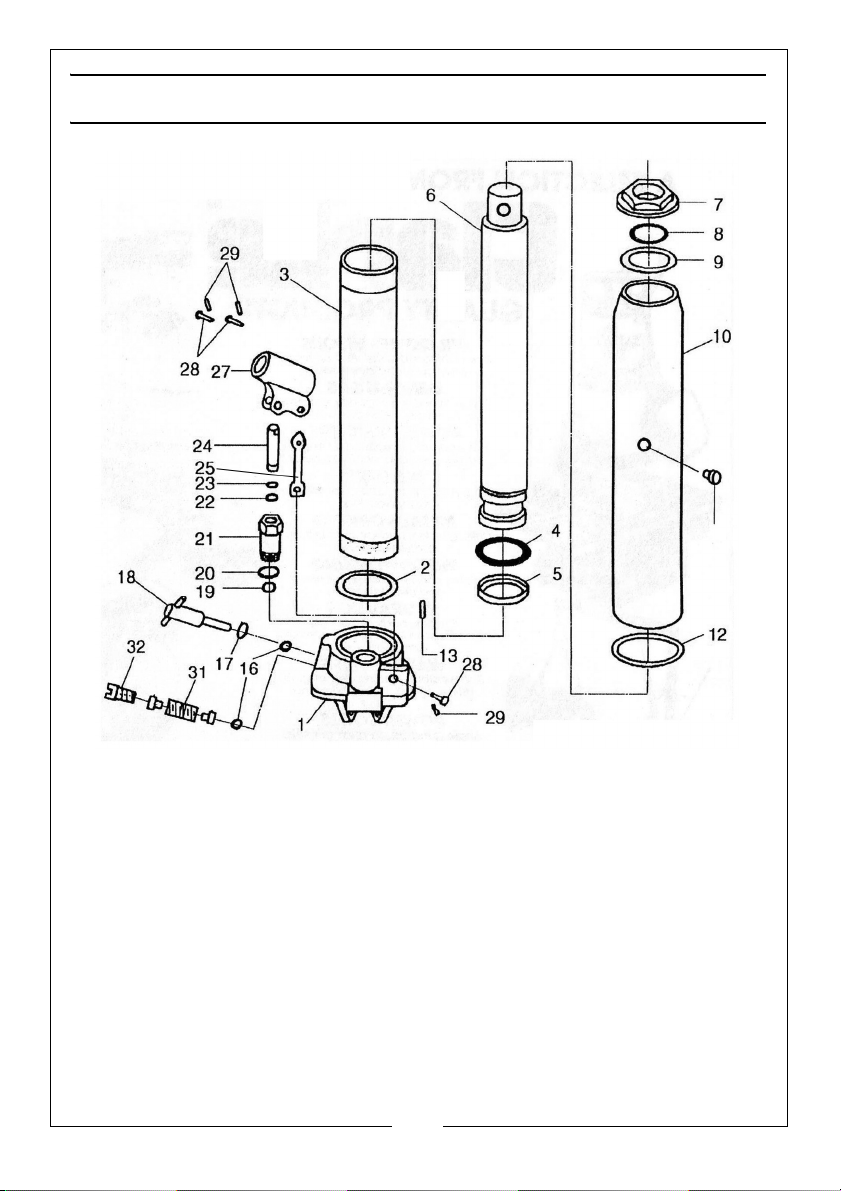
HYDRAULIC RAM PARTS
8
Parts & Service: 020 8988 7400 / E-mail: [email protected] or [email protected]
Page 9
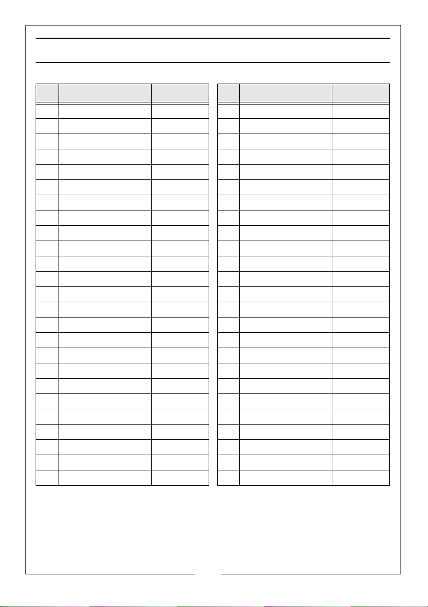
FRAME PARTS
No Description Part No No Description Part No
A Rear Support HT500101 5 Washer M14 3040572
B Front Leg HT500102 5 Lock washer M14 3040599
C Ext Support HT500103 5 Nut M14 3040616
D Main Support Post HT500104 6 Bolt M14 x 90 3040557
E Support Bracket HT500105 6 Washer M14 3040576
F Boom HT500106 6 Lock washer M14 3040599
G Boom Extension HT500107 6 Nut M14 3040616
H Ram Assembly HT500108 7 Bolt M18 x 110 3040571
I Handle HT500109 7 Washer M18 3040596
J Hook & Chain HT500110 7 Lock washer M18 3040620
1 Bolt M14 x 80 3040566 7 Nut M18 3040618
1 Washer M14 3040522 8 Bolt M16 x 85 3040627
1 Lock washer M14 3040599 8 Washer M16 3040579
1 Nut M14 3040616 8 Lock washer M16 3040585
2 Eyebolt M12 x 30 HT500112 8 Nut M16 3040604
2 Washer M12 3040578 9 Grip HT500111
2 Lock washer M12 3040584 10 Front Wheel Assy HT100013
3 Bolt M14 x 85 3040625 11 Castor Assy HT100014
3 Washer M14 3040572 12 Bolt M8 x 19 3040495
3 Lock washer M14 3040599 12 Washer M8 3040576
3 Nut M14 3040616 12 Lock washer M8 3040582
4 Eyebolt M14 x 35 HT500115 Label (model) HT500116
4 Washer M14 3040572 Label (weight) HT500117
4 Lock washer M14 3040599 Label (Strong-arm) 2001352
5 Bolt M14 x 35 3040622
9
Parts & Service: 020 8988 7400 / E-mail: [email protected] or [email protected]
Page 10
Page 11
DECLARATION OF CONFORMITY
11
Parts & Service: 020 8988 7400 / E-mail: [email protected] or [email protected]
Page 12

 Loading...