

Page 1
Page 2

iDP3221 User’s Manual
Declaration of Conformity
Manufacturer’s Name : : Japan CBM Corporation
Manufacturer’s Address : CBM Bldg., 5-68-10, Nakano, Nakano-ku
Tokyo, 164-0001, Japan
Declare the Product
Product Name Line Thermal Printer
Model Number(s) iDP3221 Series
(iDP3221RF, iDP3221PF)
(S.No.9990001 ~ )
Conform to the following Standards
LVD : EN60950 :
EMC : EN55022 : 1998 Class A
: EN61000-3-2 : 1995
: EN61000-3-3 : 1995
: EN55024 : 1995
: EN61000-4-2 : 1995 ±4KV CD, ±8KV AD
: EN61000-4-3 : 1995 3V/m, 80MHz-1000MHz AM1KHz 80%
: EN61000-4-4 : 1995 ±1.0KV (AC mains), ±0.5KV (Signal Lines)
: EN61000-4-5 : 1995 ±1KV Normal mode, ±2KV Common mode
: EN61000-4-6 : 1996 3V, 0.15MHz-80MHz AM1KHz 80%
: EN61000-4-8 : 1993 50Hz, 3A/m (Out of scope)
: EN61000-4-11 : 1994 10 ms/95%, 500 ms/30%, 5000 ms/100%
Supplementary Information
“The product complies with the requirements of the Low Voltage Directive 73/23/EEC, 93/68/EEC and
the EMC Directive 89/336EEC, 92/31/EEC, 93/68EEC”
Place Tokyo, Japan Signature
Date August.1999
Europe Contact :
Norco Declaration AB
A11: 1997
Full Name : Mikio Moriya
Position : General Manager
R & D Department
Box 7146 S-250 07 Helsingborg Sweden
Warning
This is a Class A products. In a domestic environment this product may cause radio interference in which
case the user may be required to take adequate measures.
This declaration is applied only for 230V model.
CITIZEN
Page 3

iDP3221 User’s Manual
IMPORTANT SAFETY INSTRUCTIONS
• Read all of these instructions and save them for future reference.
• Follow all warnings and instructions marked on the product.
• Unplug this product from the wall outlet before cleaning. Do not use liquid or aerosol cleaners. Use
a damp cloth for cleaning.
• Do not use this product near water .
• Do not place this product on an unstable cart, stand or table. The product may fall, causing serious
damage to the product.
• Slots and openings on the back or bottom of the case are provided for ventilation. To ensure reliable
operation of the product and to protect it from overheating, do not block or cover these openings. The
openings should never be blocked by placing the product on a bed, sofa, rug of other similar surface.
This product should never be placed near or over a radiator or heater. This product should not be
placed in an built-in installation unless proper ventilation is provided.
• This product should be operated from the type of power source indicated on the marking label. If you
re not sure of the type of power available, consult your dealer or local power company.
• Do not allow anything to rest on the power cord. Do not place this product where the cord will be
walked on.
• If an extension cord is used with this product, make sure that the total of the ampere ratings of the
products plugged into the extension cord does not exceed the extension cord ampere rating. Also,
make sure that the total of all products plugged into the wall outlet does not exceed 15 amperes.
• Never push objects of any kind into this product through cabinet slots as they may touch dangerous
voltage points or short out parts that could result in a risk of fire or electric shock. Never spill liquid
of any kind on the product.
• Except as explained elsewhere in this manual, do not attempt to service this product by yourself.
Opening and removing the covers that are marked “Do Not Remove” may expose you to dangerous
voltage points or other risks. Refer all servicing on those compartments to service personnel.
• Unplug this product from the wall outlet and refer servicing to qualified service personnel under the
following conditions:
A. When the power cord or plug is damaged or frayed.
B. If liquid has been spilled into the product.
C. If the product has been exposed to rain or water.
D. If the product does not operate normally when the operating instructions are followed. Adjust only
those controls that are covered be the operating instructions since improper adjustment of other
controls may result in damage and will often require extensive work by a qualified technician to
restore the product to normal operation.
E. If the product has been dropped or the cabinet has been damaged.
F. If the product exhibits a distinct change in performance, indicating a need for service.
• Please keep the poly bag which this equipment is packed in away from children or throw it away to
prevent children from putting it on. Putting it on may cause suffocation.
CITIZEN
Page 4

iDP3221 User’s Manual
WICHTIGE SICHERHEITSANWEISUNGEN
• Lesen Sie die nachfolgenden Anweisungen sorgfältig durch und bewahren Sie sie auf.
• Befolgen Sie alle auf dem Drucker vermerkten Hinweise und Anweisungen. Vor dem Reinigen
grundsätzlich Stecker aus der Steckdose ziehen. Keine Flüssigkeiten oder Aerosolreiniger benutzen.
Nut mit einem feuchten Tuch abwischen.
• Der Drucker darf nicht in der Nähe von Wasser aufgestellt werden.
• Drucker nicht auf einem unstabilen Wagen, Stand oder Tisch aufstellen. Der Drucker könnte
herunterfallen und dabel beschädigt werden.
• Schlitze und Öffnungen im Gehäuse, in der Rückwand und im Boden dienen der Belüftung. Sie
dürfen keinesfalls zugedeckt oder blockiert werden, da sich der Drucker sonst überhitzt. Drucker
nicht auf ein Bett, Sofa, Teppich oder dergleichen stellen. Drucker nicht in der Nähe eines
Heizkörpers aufstellen. Drucker darf nicht eingebaut werden, falls nicht für ausreichende Belüftung
gesorgt ist.
• Drucker nur mit der auf dem Typschild angegebenen Spannung betreiben. Wenn Sie sich nicht sicher
sind, fragen Sie ihren Händler oder ihr zuständiges Elektrizitätswerk.
• Nichts auf das Stromanschlußkabel stellen. Kabel muß so verlegt werden, daß man nicht darauftreten
kann.
• Ein etwaiges Verlängerungskabel muß der Stromstärke aller daran angeschlossenen Geräte entsprechen.
• Keine Gegenstände in die Gehäuseschlitze schieben.
• Drucker darf nur da gewartet werden, wo im Handbuch angegeben, Öffnen und. Abnehmen von
Abdeckungen, die mit “Do not remove” gekennzeichenet sind, könnte gefährliche spannungführende
Stellen oder sonstige Gefahrenpunkte freilegen. Die Wartung solcher Stellen darf grundsätzlich nur
von besonders ausgebildetem Fachpersonal vorgenommen werden.
A. Wenn das Stromanschlußkabel oder der Stecker beschädigt oder durch-gescheuert ist.
B. Wenn Flüssigkeit auf dem Drucker verschüttet wurde.
C. Wenn der Drucker im Regen gestanden hat oder Wasser darauf verschüttet wurde.
D. Wenn der Drucker trotz genauer Befolgung der Betriebsvorschriften nicht richtig arbeitet. Nur die
in der Bedienungsanleitung angegebenen Einstellungen vornehmen. Ein Verstellen anderer
Bedienungselemente könnte den Drucker beschädigen und macht umständliche Arbeiten eines
qualifizierten T echnikers erforderlich, um den Drucker Wieder auf den normalen Betrieb
einzustellen.
E. Wenn der Drucker heruntergefallen ist oder das Gehäuse beschädigt wurde.
F. Wenn der Drucker in seiner Leistung nachläßt.
• Bitte halten Sie den Kunststoffbeutel, in den die Ware verpackt ist, von Kindern entfernt, oder werfen
Sie ihn weg, damit er nicht in die Hande von Kindern gerät. Das Überstülpen des Beutels kann zum
Ersticken führen.
Lärmemission kleiner 70dBA
CITIZEN
Page 5

iDP3221 User’s Manual
IMPORTANT:
installed and used in accordance with the instruction manual, may cause interference to radio
communications. It has been tested and found to comply with the limits for a Class A computing device
pursuant to Subpart J of Part 15 off FCC Rules, which are designed to provide reasonable protection against
such interference when operated in a commercial environment. Operation of this equipment in a
residential area is likely to cause interference, in which case the user at his own expense will be required to
take whatever measures may be necessary to correct the interference.
This equipment generates, uses, and can radiate radio frequency energy and if not
CAUTION: Use shielded cable for this equipment.
Sicherheitshinweis
Die Steckdose zum Anschluß dieses Druckers muß nahe dem Grät angebracht und leicht zugänglich sein.
For Uses in Canada
This digital apparatus does not exceed the class A limits for radio noise emissions from digital, apparatus,
as set out in the radio interference regulations of the Canadian department of communications.
Pour L’utilisateurs Canadiens
Cet appareil numérique ne dépasse pas les limites de carégorie a pour les émissions de bruit radio émanant
d’appareils numériques, tel que prévu dans les réglements sur l’interférence radio du départment Canadien
des communications.
CITIZEN
Page 6

iDP3221 User’s Manual
<CAUTIONS>
1. Prior to using the equipment, be sure to read this User's Manual thoroughly. Please keep it handy for reference
whenever it may be needed.
2. The information contained herein may be changed without prior notice.
3. Reproduction of part or all of this User's Manual without permission is strictly prohibited.
4. Never service, disassemble, or repair parts that are not mentioned in this User's Manual.
5. Note that we will not be responsible for damages attributable to a user's incorrect operation/ handling or an
improper operating environment.
6. Operate the equipment only as described in this User's Manual; otherwise accidents or problems may result.
7. Data are basically temporary; they cannot be stored or saved permanently or for a long time. Please note that
we will not be responsible for damages or losses of profit resulting from losses of the data attributable to
accidents, repairs, tests, and so on.
8. If you have any questions or notice any clerical errors or omissions regarding the information in this manual,
please contact our office.
9. Please note that, notwithstanding Item 8 above, we will not be responsible for any effects resulting from
operation of the equipment.
CITIZEN
Page 7

iDP3221 User’s Manual
SAFETY PRECAUTIONS ----- BE SURE TO OBSERVE
In order to prevent hazards to an operator or other persons and damage to property, be sure to
observe the following precautions.
z
The following describes the degrees of hazard and damages that can occur if the given instructions are
neglected or the equipment is incorrectly operated.
WARNING Negligence of this precaution may result in death or serious injury.
CAUTION Negligence of this precaution may result in injury or damage to property.
This is an illustration mark used to alert your attention.
This is an illustration mark used to indicate such information as an instruction or the like.
CITIZEN
Page 8
iDP3221 User’s Manual
WARNING
z
Never handle the equipment in the following manners, as it may break, become out of order, or
overheat causing smoke and resulting in fire or electric shock.
If the equipment is used in an abnormal condition, such as when broken, then problems, smoke
emission, abnormal odor/noise, and fire can result. If an abnormal condition exists, be sure to turn off
the power, disconnect the power plug from a plug socket, and contact our dealer. Never repair the
equipment on your own - it is very dangerous.
• Do not allow the equipment to receive a strong impact or shock, such as kicking, stomping, hitting,
dropping, and the like.
• Install the equipment in a well-ventilated place. Do not use it in such a manner that its ventilation
port will be blocked.
• Do not install the equipment in a place like a laboratory where chemical reactions are expected, or in a
place where salt or gases are contained in the air.
• Do not connect/disconnect a power cord or a data cable, while holding the cable. Do not pull, install,
use, or carry the equipment in such a manner that force will be applied to the cables.
• Do not drop or insert any foreign substances, such as clips or pins, into the equipment.
• Do not spill any liquid or spray any chemical-containing liquid over the equipment. If any liquid is
spilled on it, turn off the power, disconnect the power cable and power cord from the plug socket, and
so on, and contact our dealer.
• Do not disassemble or remodel the equipment. Negligence of this may cause fire or electric shock.
• Should you drop or break this AC adapter by any chance, unplug it immediately and contact our office.
Using it in that condition may result in fire or electric shock.
• Should water enter inside the equipment by any chance, unplug it and contact our office. Using it in
that condition may result in fire or electric shock.
• Use the equipment only with the specified commercial power supply. Negligence of this may result
in fire, electric shock, or problems.
• Do not damage, break, process, bend/pull by force, twist, or bundle an AC adapter cord. Also, do not
put a heavy substance on it or heat it. The AC adapter could be broken, resulting in fire, electric
shock, or trouble. If the AC adapter cord is damaged, contact our office.
• Do not connect/disconnect the AC adapter with wet hands. It may result in electric shock or other
problems.
• Do not overload a single electrical outlet, using a table tap or a current tap socket. It may result in fire
or electric shock.
z
An equipment packing bag must be discarded or kept away from children. A child can suffocate if the
bag is placed over the head.
CITIZEN
Page 9

iDP3221 User’s Manual
PRECAUTIONS FOR INSTALLATION
• Do not use or store the equipment in a place exposed to fire, moisture, or direct sunshine, or in a place
near a heater or thermal device where the prescribed operating temperature and humidity are not met, or
in a place exposed to much oil, iron powder, or dust. The equipment may become out of order , emit
smoke, or catch fire.
• Do not install or use the equipment in a place like a laboratory where chemical reactions are expected,
or in a place where salt or gases are contained in the air. There is a danger of fire or electric shock.
• Install the printer on a flat, stable desk or table that is free from vibration, in a well-ventilated place.
• Do not place anything on the printer or leave small objects, like a clip or pin, around it. A foreign
object could cause trouble if it gets inside.
• Do not use the equipment near a radio or TV receiver. Do not share the power from a plug socket a
radio or TV receiver is connected to. It may cause a reception problem.
• Use the equipment only at the specified power supply, voltage and frequency. Otherwise, it may emit
smoke and catch fire or cause other problems.
• Connect only the specified power source. Use of an unspecified power source could cause trouble or
smoke/fire.
• Confirm that a plug socket used for connection has sufficient capacity.
• Avoid connecting a power cable to a plug socket shared by other devices or extending the wiring too far.
It may result in the cable catching fire or a power outage. Also, do not step on or apply an excessive
force (Pull, load) to the cable, and do not use the printer with such a force applied to it.
• Never connect a grounding cable (Frame ground) to a gas pipe. There is a danger of explosion.
When connecting or disconnecting the grounding cable, be sure to disconnect the power cable and the
power plug from the plug socket.
• When connecting/disconnecting the cables, be sure to turn off the power first, including the connected
side, and then connect/disconnect them, holding a plug and a connector. Pulling the cable itself could
cause it to snap or become damaged.
• Connect a power cable or a connector cable securely. If a reverse-polarity connection is made,
internal elements may be broken or a mating device may be adversely affected.
• Use a shielding wire or twisted pair wire for a signal line, in order to minimize noise effect. Do not
route the cable too long or connect it to a noisy device. Connection to a noisy device could cause
erroneous printing due to corrupt data, and so on.
• When a drawer kick connector is provided, do not connect any device other than the prescribed solenoid
specifications. Negligence of this could cause trouble.
• Use the equipment in an environment where there is a plug socket near the main body and you can
easily disconnect the power plug from it, to shut off the power.
• When the equipment will not be used for a long period of time, unplug it and remove the paper roll from
it.
• When transporting the equipment, remove the paper roll from the paper holder.
CITIZEN
Page 10

iDP3221 User’s Manual
PRECAUTIONS FOR HANDLING
Do not handle the equipment in the following manners, because problems may result.
• Do not use any other power source besides the accessory AC adapter. Also, do not use the AC adapter
for other purposes.
• Do not print without paper.
• Do not drop or put any foreign object, such as a clip, pin, or the like, inside the printer.
• Do not spill any liquid or spray any chemical-containing liquid over the equipment.
• Do not stamp on, drop, hit, or give a strong shock to the equipment.
• Never use a pointed object, such as a pen, to operate the operation panel.
• Do not use Scotch tape to fasten paper together for continuous use. It could damage the printing head.
• Never pull the set paper forcibly.
To Prevent Injury and Spreading of Damage
• Do not touch the printing part of the print head.
• When turning on the power, do not touch the moving parts, such as a cutter and gear inside the main
body, or electric parts.
• Be careful to avoid bodily injure or damaging other objects with an edge of sheet metal.
• Should any error occur while operating the equipment, stop it immediately and disconnect the power
plug from the plug socket.
• Should a problem occur, leave solving it to our serviceman. Do not disassemble the equipment on
your own.
CITIZEN
Page 11
iDP3221 User’s Manual
DAILY MAINTENANCE
• At the time of maintenance, be sure to turn off the power switch of the printer and unplug it from the
socket.
• When cleaning the platen, wipe off dust or dirt from the platen with a cotton swab dipped in ethyl
alcohol.
• Use a dry soft cloth to wipe off stains and dust from the surfaces of the main body case. For severe
soiling, dip the cloth in water and wring it, for wiping off the soil. Never use organic solvents, such as
alcohol, thinner, trichlene, benzene, ketone, or chemical dusters.
• If the equipment is contaminated with paper powder, use a soft brush to clean it. Be careful not to
damage the printing head.
CAUTION:
z
Cleaning the Printing Head
1. Referring to "4.6 Removing Paper Jam," detach the platen roller unit.
2. Moisten gauze slightly with alcohol, and clean the heating surface of the printing head with it.
3. Reattach the platen roller unit.
CAUTION:
The printing head and motor are very hot. Be careful not to touch them
immediatelyafter printing.
The printing head and motor are very hot. Be careful not to touch them
immediately after printing. Do not touch the heating surface of the head with a bare
hand or metal.
CITIZEN
Page 12

A caution label is stuck onto the following place. Carefully read
the cautions on operation to correctly use the printer.
This label warns that the head becomes hot in operation,
and touching it may result in burns.
iDP3221 User’s Manual
CITIZEN
Page 13

iDP3221 User’s Manual
CONTENTS
1. OUTLINE ...............................................................................................................................................................1
1.1 Features....................................................................................................................................................................... 1
1.2 Unpacking................................................................................................................................................................... 1
2. BASIC SPECIFICATIONS...................................................................................................................................3
2.1 Model Classifications ................................................................................................................................................. 3
2.2 Basic Specifications.................................................................................................................................................... 4
2.3 Paper Specifications.................................................................................................................................................... 5
2.3.1 Recommended Paper ......................................................................................................................................... 5
2.3.2 Printing Position ................................................................................................................................................ 5
2.3.3 Head and Paper Cutter Layout........................................................................................................................... 6
3. OUTER APPEARANCE AND COMPONENT PARTS.....................................................................................7
4. OPERATION..........................................................................................................................................................8
4.1 Connecting AC Adapter ............................................................................................................................................. 8
4.2 Connecting Interface Cable ........................................................................................................................................ 9
4.3 Inserting the Paper...................................................................................................................................................... 9
4.4 How to Remove Remaining Paper Roll.................................................................................................................... 10
4.4.1 Inserting the Paper ........................................................................................................................................... 10
4.4.2 Manually Inserting the Paper........................................................................................................................... 12
4.5 How to Remove Remaining Paper Roll.................................................................................................................... 13
4.6 Eliminating the Paper Jam........................................................................................................................................ 14
4.7 Unlocking t he Cutter................................................................................................................................................. 16
4.8 Clearing the Head ..................................................................................................................................................... 17
4.9 Operation Panel and Display of Error....................................................................................................................... 18
4.10 Hexadecimal Dumps................................................................................................................................................. 20
5. DIP SWITCH SETTING.....................................................................................................................................21
5.1 Location of DIP Switch ............................................................................................................................................ 21
5.2 DIP Switch Functio n................................................................................................................................................. 22
6. PARALLEL INTERFACE..................................................................................................................................23
6.1 Bi-directional Parallel Interface (IEEE 1284)........................................................................................................... 23
6.1.1 Compatibility Mode......................................................................................................................................... 23
6.1.2 Reverse Mode.................................................................................................................................................. 23
CITIZEN
Page 14

iDP3221 User’s Manual
6.1.3 Connector Pin Assignment .............................................................................................................................. 24
6.2 Parallel Interface (CENTRONICS) ...................................................................................................................... 25
6.2.1 Specifications................................................................................................................................................... 25
6.2.2 Connector's Pin Configuration......................................................................................................................... 25
6.3 Input and Output Signals ....................................................................................................................................... 26
6.3.1 Input and Output Signals................................................................................................................................. 26
6.3.2 Electrical Characteristics ................................................................................................................................. 27
6.3.3 Timing Chart.................................................................................................................................................... 28
6.3.4 Data Receiving Control ................................................................................................................................... 28
6.3.5 Buffering.......................................................................................................................................................... 28
7. SERIAL INTERFACE.........................................................................................................................................29
7.1 Specifications............................................................................................................................................................ 29
7.2 Connector's Pin Configuration.................................................................................................................................. 29
7.3 Input and Output Signals .......................................................................................................................................... 30
7.3.1 Input and Output Signals................................................................................................................................. 30
7.3.2 Data Configuration .......................................................................................................................................... 31
7.3.3 Error Detection ................................................................................................................................................ 31
7.3.4 Data Receiving Control ................................................................................................................................... 32
7.3.5 Buffering.......................................................................................................................................................... 32
7.3.6 Electrical Characteristics ................................................................................................................................. 32
8. DRAWER KICK-OUT CONNECTOR, POWER CONNECTOR..................................................................33
8.1 Drawer Kick-Out Connector..................................................................................................................................... 33
8.1.1 Specifications of Drawer Kic k-Out Connector................................................................................................ 33
8.1.2 Connector's Pin Configuration......................................................................................................................... 33
8.2 Power Connector ...................................................................................................................................................... 34
9. MAINTENANCE AND SERVICE.....................................................................................................................35
10. PRINT CONTROL FUNCTIONS......................................................................................................................36
10.1 Command List .......................................................................................................................................................... 36
10.2 Command Details ..................................................................................................................................................... 39
10.2.1 Descriptions of Each Item ............................................................................................................................... 39
10.2.2 Command Details ............................................................................................................................................ 40
CITIZEN
Page 15

iDP3221 User’s Manual
11. CHARACTER CODES TABLE.......................................................................................................................112
11.1 CodePage 00H to 7FH & PC437(USA, European, Standard) .............................................................................. .. 112
11.2 Code Page Katakana(Japanese) .............................................................................................................................. 113
11.3 Codepage PC850(Multilingual).............................................................................................................................. 114
11.4 Codepage PC860(Portguese).................................................................................................................................. 115
11.5 Codepage PC893(Canadian-French)...................................................................................................................... 116
11.6 Codepage PC865(Nordic)....................................................................................................................................... 117
11.7 Blank page(For user setting)................................................................................................................................... 118
11.8 International Character Codes Table....................................................................................................................... 119
APPENDIX 1. PAGE MODE...............................................................................................................................120
APPENDIX 2. BI-DIRECTIONAL PARALLEL INTERFACE......................................................................128
1. Overview................................................................................................................................................................ 128
1.1 Parallel Interface Communication Modes .............................................................................................................. 128
1.2 Interfacing P hase .................................................................................................................................................... 129
2. Negotiation ............................................................................................................................................................ 130
2.1 Overview ....................................................................................................................................................... 130
2.2 Negotiation Procedure ................................................................................................................................... 130
2.3 Precautions..................................................................................................................................................... 131
2.4 Data Communication from Printer to Host.................................................................................................... 132
2.4.1 Nibble Mode ............................................................................................................................................ 132
2.4.2 Byte Mode................................................................................................................................................ 132
2.5 Device ID....................................................................................................................................................... 134
2.6 Terminator ..................................................................................................................................................... 135
APPENDIX 3 IDENTIFICATION OF SEND STATUS...................................................................................136
APPENDIX 4. BLOCK DIAGRAM ...................................................................................................................137
APPENDIX 5. OUTLINEDRAWING................................................................................................................138
<<< German >>>
4. BETRIEB............................................................................................................................................................148
4.1 Anschließen des Netzteils....................................................................................................................................... 148
4.2 Anschließen des Schnittstellenkabels .......................................................................................... ........................... 149
4.3 Anschluß des Schubladenausschubsteckers............................................................................................................ 149
4.4 Einlegen des Papiers............................................................................................................................................... 150
CITIZEN
Page 16

iDP3221 User’s Manual
4.4.1 Einlegen des Papiers...................................................................................................................................... 150
4.4.2 Papier manuell einlegen................................................................................................................................. 152
4.5 Herausnehmen der Restpapierrolle......................................................................................................................... 153
4.6 Beseitigen von Papierstau....................................................................................................................................... 154
4.7 Initialisierung des Schneidemechanismus .............................................................................................................. 156
4.8
Kopf reinigen..................................................................................................................................................157
4.9 Bedienfeld und Fehleranzeigen .............................................................................................................................. 158
4.10 Hexadezimal-Dumps .............................................................................................................................................. 160
5. DIP-SCHALTEREINSTELLUNG...................................................................................................................161
5.1 Lage der DIP-Schalter ............................................................................................................................................ 161
5.2 DIP-Schalterfunktion.............................................................................................................................................. 162
6. PARALLELSCHNITTSTELLE.......................................................................................................................163
6.1 Bidirektionale Parallelschnittstelle (IEEE 1284).................................................................................................... 163
6.1.1 Kompatibilitätsmodus.................................................................................................................................... 163
6.1.2 Reverse-Modus.............................................................................................................................................. 163
6.1.3 Pinbelegung der Buchse ................................................................................................................................ 164
9. WARTUNG UND DIENST................................................................................................................................165
ANHANG 1. SEITENMODUS.........................................................................................................................166
ANHANG 2. BIDIREKTIONALE PARALLELSCHNITTSTELLE...........................................................174
1. Übersicht................................................................................................................................................................ 174
1.1 Übertragungsmodi der Parallelschnittstelle................................................................................................... 174
1.2 Kommunikationsphasen ................................................................................................................................ 175
2. Verhandlung.......................................................................................................................................................... 176
2.1 Übersicht........................................................................................................................................................ 176
2.2 Vorgehensweise bei der Verhandlung............................................................................................................ 176
2.3 Besonders beachten ....................................................................................................................................... 177
2.4 Datenübertragung vom Drucker zum Host-Computer................................................................................... 179
2.4.1 Nibble Mode ............................................................................................................................................ 179
2.4.2 Byte Mode................................................................................................................................................ 180
2.5 Geräte-ID....................................................................................................................................................... 181
2.6 Terminierung.................................................................................................................................................. 182
ANHANG 3. ERMITTLUNG DES SENDESTATUS.....................................................................................184
CITIZEN
Page 17

iDP3221 User’s Manual
1. OUTLINE
This is a small line thermal printer developed to be used for various data communication terminals, POS
terminals, kitchen printer, and so on. With its abundant features, it can be widely used for various types of
applications. Prior to using the printer, read this manual thoroughly to understand its contents..
1.1 Features
1. Small, lightweight, with a small footprint.
2. Designed with a reduced number of components to ensure low cost.
3. Paper is added by simply placing the paper and closing the cover.
4. A removable platen mechanism simplifies maintenance (e.g. paper handling and head cleaning).
5. Line thermal printing for high speed and low noise.
6. A long-life head with a simple mechanism to ensure high reliability.
7. Built-in input buffer.
8. Bar code printing (with special commands).
9. Built-in drawer kick-out interface.
10. Auto cutter fitted as standard.
11. User registration of external characters.
1.2 Unpacking
(1) When unpacking the printer, confirm that the following parts are provided.
• Printer body -----1 unit
• Sample paper roll -----1 roll
• AC adapter -----1 piece
• AC power cord -----1 piece
• User's manual ----- 1 copy
Printer Body
Sample Paper Roll
AC Adapter
User's Manual
AC Power Cord
1
CITIZEN
Page 18

iDP3221 User’s Manual
(2) Before using the printer, remove the protective paper for the head as shown below:
1. Open the printer cover.
2. Pull the platen levers at both sides of the platen roller unit in the direction of the arrows.
3. Pull the protective paper in the direction of the arrow.
4. Insert a sheet of printer paper between the platen roller and the head when the printer is to remain
unused for a long period of time.
Platen Lever
Printer Cover
CAUTION :
• Install the printer on a flat and stable desk.
• Do not install the printer near a heater or in a place exposed to direct sunlight.
• Do not use the printer in a high-temperature, high-humidity, and contaminated environment.
• Do not allow dew condensation on the printer. If dew is condensed on it, leave the power turned off until
dew condensation is gone.
2
CITIZEN
Page 19

2. BASIC SPECIFICATIONS
2.1 Model Classifications
The models are classified by the following designation method:
iDP3221 - R F 120
Model Name
iDP3221 User’s Manual
AC Adapter
* Special AC Adapter and AC Power Cord
31AD-U (120V AC --- 3-core cord)
31AD-E (230V AC --- Class I cord)
120: 120 V AC
230: 230 V AC
Characters Set
F: International
Interface
R: Serial (RS-232C)
P: Parallel (IEEE 1284 Compliant,
Bi-directional communication)
3
CITIZEN
Page 20

2.2 Basic Specifications
Item
Model
iDP3221
iDP3221
–RF120
–PF120
Printing system Line thermal dot printing
Printing width 72.192 mm/512 dots
Dot density Width: 0.141 mm, Length: 180 DPI (0.141 mm)
Printing speed
63.45 mm/sec.
(At maximum speed, print density level 2), (450-dot line/sec.)
Printing columns 42 columns (Font A) , 56 columns (Font B)
Printing size
1.41×3.39 mm (Font A) , 0.99×3.39 mm (Font B)
Line pitch 4.23 mm (1/6 inch)
Can be set with a command (See 10.2 "Command Details.")
Character types Alphanumeric, international characters, extended graphic
Bar code type
Paper
UPC-A/E, JAN(EAN) 13-/18-column, ITF, CODE 39, CODE 128, CODABAR,
CODE 93
Thermal paper roll : 80 + 0/- 1 mm×φ83 (max.) mm
(See Paper Specifications)
Interface Serial (RS-232C)
Parallel (IEEE 1284 compliant) (Bi-directional communication)
Input buffer 4 KB or 72 bytes (Selectable with the DIP switch)
Supply DC voltage 24 V DC +/- 7%
Power consumption 100 W
AC adapter
Rated input : 100∼240 V AC, 50/60 Hz, 120 VA
Rated output : 24 V DC, 1.8 A
Type 31AD-U 31AD-E
Weight Main body: Approx. 1.3 Kg
AC adapter: Approx. 450 g
Outer dimensions
Operating temperature
152 (W) × 201 (D) × 123 (H) mm
5 ∼ 40°C, 35 ∼ 85 % RH (No dew condensation)
and humidity
Storage temperature and
-20 ∼ 60°C, 10 ∼ 90% RH (No dew condensation)
humidity
Reliability Printing head life:
Pulse resistance : 50 million pulses or more (Print rate 12.5%)
Wear resistance : 50 km or more (With recommended thermal paper at
normal temperature and humidity)
Auto cutter life:
500,000 cuts (With recommended thermal paper at normal temperature and
humidity)
Applicable standard *1 UL, C-UL, FCC Class-A TUV, GS, CE Marking
Note: *1 indicates the standard satisfied when the AC adapter (31AD series) is used.
iDP3221
iDP3221
iDP3221 User’s Manual
–RF230
–PF230
4
CITIZEN
Page 21

iDP3221 User’s Manual
2.3 Paper Specifications
2.3.1 Recommended Paper
• Type : Thermal paper
• Paper width : 80 + 0/- 1 mm
• Paper thickness : 60∼75µm
• Roll diameter : φ83 mm or less
• Printing surface : Outside of the roll (Surface)
• Recommended paper : TF50KS-E2C (Monochrome) made by NIPPON SEISHI or its equivalent
•Core : φ12 mm (Inner diameter), φ18 mm (Outer diameter)
CAUTION:
• Use of non-specified paper may cause irregularity of print density. If this is the case, use the DIP switch
to select print density. (See 5. DIP SWITCH SETTING)
• Do not paste the paper to the core.
• If the paper comes in contact with a chemical or oil, it may discolor or lose a record.
• Do not rub the paper surface strongly with a nail or hard metal. It may discolor.
•. Discoloring starts at about 70°C. Watch out for effects of heat, humidity, light, and so on.
2.3.2 Printing Position
Paper Width: 80 mm
Printing Area: 72.2 mm
About 3.9 mmAbout 3.9 mm
5
CITIZEN
Page 22

2.3.3 Head and Paper Cutter Layout
Paper Outlet
Auto Cutter Position
Head Printing Position
About
iDP3221 User’s Manual
15.5 mm
About 42 mm
Paper Feed Direction
6
CITIZEN
Page 23

3. OUTER APPEARANCE AND COMPONENT PARTS
Printer Cover
iDP3221 User’s Manual
Upper Cover
Power Switch
POWER Lamp
ERROR Lamp
FEED Switch
Interface Connector
Power Connector
7
Grounding Terminal
Drawer Kick-Out Connector
CITIZEN
Page 24
iDP3221 User’s Manual
4. OPERATION
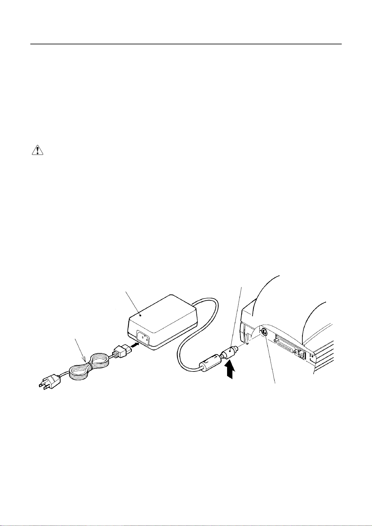
4.1 Connecting AC Adapter
1. Turn off the power.
2. With the flat surface on the AC adapter cable connector facing downwards, plug it into the power
connector at the rear of the printer.
3. Connect the AC power cord to the AC adapter, and plug it into an AC outlet.
CAUTION:
• Use only the specified AC adapter.
• When disconnecting/reconnecting the cable connector of the AC adapter, be sure to hold the connector.
• Separate the AC adapter from other noise-generating devices.
• Pulling the AC power cord may damage it, resulting in a fire, electric shock, or snapping.
• If a thunder/lightning storm is nearby, disconnect the AC adapter from the socket and do not use the printer,
because a fire or electric shock may occur.
• Do not put the AC power cord close to a heating device. Its coating can melt and cause a fire or electric
shock.
• After using the printer or when not using it for a long period of time, be sure to unplug the AC adapter from
a plug socket for your safety.
AC Adapter
AC Power Cord
Cable Connector
Flat Surface
Power Connector
8
CITIZEN
Page 25

4.2 Connecting Interface Cable
1. Turn off the power. (Mating side included)
2. Check the top and bottom of cable terminals, and connect to the interface connector.
3. Fix the cable terminals. Serial interface : Tighten screws, to fix it.
Parallel interface : Turn clamps, to fix it.
4. Connect the cable to the host computer.
iDP3221 User’s Manual
Serial Interface Cable
Serial Interface Connector
Parallel Interface Connector
Clamp
Parallel Interface Cable
4.3 Connecting the Drawer Kick-Out Connector
1. Turn off the power.
2. Check the top and bottom of the drawer kick-out cable connector and connect it to the drawer kick-out
connector located on the back of the printer.
3. Screw the grounding cable of the drawer to the grounding terminal of the printer.
CAUTION:
• Connect only the prescribed drawer (Solenoid) to the drawer kick-out connector.
(Do not connect a telephone line.)
Drawer Kick-Out Connector
Drawer Kick-Out Cable Connector
Grounding Cable
9
CITIZEN
Page 26

4.4 Inserting the Paper
4.4.1 Inserting the Paper
1. Turn on the power.
2. Put your hands in the concave parts on both sides of the printer cover, and open it until it comes
to a stop.
3. Cut the end of the paper roll at close to a right angle.
iDP3221 User’s Manual
4. Ensure that the paper roll is placed correct side up in the roller part in the upper cover.
5. Check that the paper roll is between the platen levers, pull the end of the paper out to the edge
of the upper cover, and close the printer cover. The paper is automatically fed in and comes
out the paper outlet of the printer.
6. Cut the surplus paper by the tear bar at the paper outlet of the auto cutter.
Concave Part
Platen Lever
10
Platen Lever
Upper Cover
CITIZEN
Page 27

iDP3221 User’s Manual
CAUTION:
• Be sure to use the specified paper roll.
• Use of non-specified paper may not guarantee the print quality, printing head life, and so on.
• The printer cover is not detachable. Do not apply an excessive force beyond its stopping position.
• Do not insert a ragged or dog-eared end of the paper roll, because it could result in a paper jam or insertion
error.
• Always pull the end of the paper roll out to the edge of the uppercover. Take care to ensure that the paper
is not beyond or before the edge of the cover.
• When the paper roll has been set in place, the end of the paper may be fed from the paper outlet in a folded
or creased condition. If the paper does not appear at the paper outlet, check the end of the paper and set it in
place again.
• If the paper roll is skewed, pull the platen lever forward to correct its position.
• Do not open the printer cover while printing.
• Holding or touching the paper roll during printing may result in a paper jam.
• When the auto cutter is used for full cutting, remove the cut paper before starting the next print operation to
prevent jamming.
11
CITIZEN
Page 28

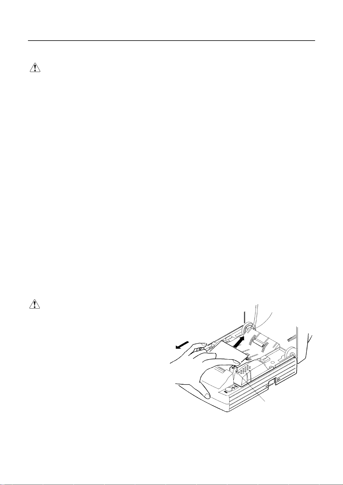
4.4.2 Manually Inserting the Paper
The manual insertion is effective when DIP switch DS1-2 is set to ON to disable the cover open detection.
1. Turn on the power.
2. Put your hands in the concave parts on both sides of the printer cover , and open it until it comes
to a stop.
3. Cut the end of the paper roll at close to a right angle.
iDP3221 User’s Manual
4. Ensure that the paper roll is placed correct side up in the roller part in the upper cover.
5. Insert the end of paper roll straight between the platen roller and the printing head.
6. The paper is automatically pulled into the platen roller and fed to the auto cutter (and comes out
of the paper outlet of the cutter a little).
7. When the printer cover is closed, the paper is fed in a few more lines, cut, and printing is then
possible. Remove cut paper before printing.
Concave Part
12
Upper Cover
CITIZEN
Page 29
iDP3221 User’s Manual
CAUTION:
• Be sure to use the specified paper roll.
• Use of non-specified paper may not guarantee the print quality, printing head life, and so on.
• The printer cover is not detachable. Do not apply an excessive force beyond its stopping position.
• Do not insert a ragged or dog-eared end of the paper roll, because it could result in a paper jam or insertion
error.
• Rewind the paper roll if the paper is slack. If there is too much slack in the paper roll, since the paper roll
is apart from the paper sensor, the printer may perform the operation described in 6. and 7. in 4.4.2
"Manually Inserting the Paper."
• If the paper roll is skewed, pull the platen lever forward to correct its position.
• When the paper roll has been set in place, the end of the paper may be fed from the paper outlet in a folded
or creased condition. If the paper does not appear at the paper outlet, check the end of the paper and set it in
place again.
• Do not open the printer cover while printing.
• Holding or touching the paper roll during printing may result in a paper jam.
• When the auto cutter is used for full cutting, remove the cut paper before starting the next print operation to
prevent jamming.
4.5 How to Remove Remaining Paper Roll
1. Open the printer cover.
2. Pull both platen levers in the direction of the arrow. The platen roller is then separated from the printing
head and the paper may then be removed.
CAUTION:
• When removing the paper (in either the
forward or reverse direction), pull the
platen levers in the direction of the arrow.
13
Platen Lever
CITIZEN
Page 30

iDP3221 User’s Manual
4.6 Eliminating the Paper Jam
1. Turn off the power.
2. Open the printer cover.
3. Cut the paper roll near the paper insertion slot.
4. Move the head springs on either side in the directions of the arrows to unhook them from the hook part of
the chassis, and lift them. (See the figure on the next page.)
5. Remove the platen roller unit by lifting both platen levers.
6. Remove the remaining paper roll completely from the paper passage.
7. Check the direction of the platen roller unit and attach it so that its left end is securely engaged with the
bush guide of the chassis as shown in the figure.
8. While lightly holding the platen unit, hook the head springs on the hooks.
CAUTION:
• Do not carry out this work just after printing because the printing head is very hot.
• Do not move the head springs beyond the movable limits.
• When eliminating remaining paper, do not touch the heating surface of the head with a bare hand or metal
piece.
• When putting back the platen roller unit, be sure to confirm that it is correctly reattached.
• Always turn off the power before removing the platen roller unit.
14
CITIZEN
Page 31

iDP3221 User’s Manual
Hook of the Chassis
Head Springs
Platen Roller Unit
Guide Bush
15
Guide Bush
CITIZEN
Page 32

iDP3221 User’s Manual
4.7 Unlocking the Cutter
1. Remove the paper from the paper passage as described in 4.6 "Eliminating the Paper Jam."
2. Turn on the power. The auto cutter initialization begins and the cutter returns to its home position.
Then, the alarm is cleared.
3. If the cutter does not return to its home position after the power has been turned on, do the following.
Turn off the power, and return the auto cutter blade to its home position by turning the emergency knob
on the bottom of the auto cutter in the direction indicated by the arrow, using tweezers, screwdrivers,
etc.
4. With tweezers or similar, totally remove remaining paper from the cutter blade area.
CAUTION:
• Do not carry out this work just after printing because the printing head is very hot.
• When eliminating remaining paper, do not touch the heating surface of the head with a bare hand or metal
piece.
• The cutter is enabled/disabled with the DIP switch. When using the printer with the cutter disabled, be
sure that the cutter has returned to the home position. If it is not, return it to the home position by turning
the emergency knob on the bottom of the printer.
Emergency Knob
16
CITIZEN
Page 33

iDP3221 User’s Manual
4.8 Cleaning the Head
1. Remove the platen roller unit referring to 4.6 "Eliminating the Paper Jam."
2. Clean the heating surface of the head by wiping it with a cotton swab dampened with a small amount of
ethyl alcohol.
3. Attach the platen roller unit.
CAUTION:
• Do not touch the heating surface of the head with a bare hand or metal.
• Do not carry out this work just after printing because the printing head is very hot.
• Always turn off the power before removing the platen roller unit.
Platen Roller Unit
Heating Surface of the Printing Head
Emergency Knob
17
CITIZEN
Page 34

4.9 Operation Panel and Display of Error
1. POWER lamp (Green)
Illuminated if the power is turned on. Also, flashes to indicate a memory error.
2. ERROR lamp (Red)
Indicates an error by illuminating or blinking the lamps.
Error POWER Lamp ERROR Lamp Reset
iDP3221 User’s Manual
Memory check error
Quick blinking
Cover open ON ON Close the cover.
Head overheat ON
Paper near end ON ON
Paper end ON ON Set a new paper roll.
Cutter motor lock ON
Macro execution wait ON
ON Cannot be reset
Automatically reset by a
temperature drop
Set a new paper roll after a print
stop.
Quick + Slow
blinking
Slow blinking
Eliminate a paper jam.
Press the FEED switch.
<Error Details>
Cover open ----- Opening of the printer cover is detected by the printer cover open sensor. The
ERROR lamp is then lit and print operation is halted. Note that the DIP switch
may be set to allow paper feed while the printer cover is open.
Head overheat ----- If the temperature of the printing head rises (about 65°C or more), in order to protect
it against overheating, a printing head temperature sensor will be activated to stop
printing. If the temperature drops (about 60°C), printing will be automatically
resumed.
Paper near end ----- When the paper roll reaches a set diameter, the ERROR lamp is lit by the paper near
end sensor located on the side of the roller part of the upper cover. (See the
function of the control codes ESC c3 and ESC c4 in "PRINT CONTROL
FUNCTION.")
Paper end ----- When the paper roll runs out, the paper sensor located in the paper path near the
printing head detects paper end and the ERROR lamp is lit, resulting in halting
printing. (See the function of the control codes ESC c3 and ESC c4 in "PRINT
CONTROL FUNCTION.") When paper is inserted into the paper path, loading of
the paper roll begins.
18
CITIZEN
Page 35

iDP3221 User’s Manual
Cutter motor lock ----- If the cutter position sensor in the cutter unit is left turned on or off for approx. 1
second while the cutter motor is running, cutter operation and printing will be
suspended, determining it to be motor lock. See 4.7 "Unlocking the Cutter."
3. FEED switch
Press and release this switch immediately to feed paper by one line. Press it continuously to feed paper
continuously. Press this switch to execute macro when the system is awaiting macro-execution.
4. FEED and Power Switches
Press the FEED and POWER switches simultaneously to run self-print.
POWER Lamp (Green)
ERROR Lamp (Red)
FEED Switch
19
CITIZEN
Page 36

4.10 Hexadecimal Dumps
1. The Hexadecimal Dump Function
This function allows data sent from the host to be printed in hexadecimal notation, together with a
corresponding character printout.
2. Starting the Hexadecimal Dump
Press the POWER switch and FEED switch simultaneously with the cover opened. When the cover is
closed, "Hexadecimal Dump" is printed on the paper and the received data is then printed in hexadecimal
format with the corresponding character printout.
Notes: • "." is printed when the data has no corresponding character.
• Only the DLE EOT and DLE ENQ commands are usable during the hexadecimal dump.
• When less than one line of data is available for printing, pressing the FEEDswitch prints
a single line.
3. Terminating the Hexadecimal Dump
After the data has been printed, printing is terminated by either turning off the power, or by receipt of a
iDP3221 User’s Manual
reset signal.
Print Example>
<
20
CITIZEN
Page 37

iDP3221 User’s Manual
5. DIP SWITCH SETTING
5.1 Location of DIP Switch
1. Turn off the power.
2. Remove the bottom cover by removing the two screws and turning it over in the direction shown by the
arrow to remove it.
Bottom Cover
21
CITIZEN
Page 38

5.2 DIP Switch Function
DS1
No. Function ON OFF Upon Shipment
1 Cutter Enabled Disabled ON
2 Cover open Disabled Enabled OFF
3 CR switching LF operation Ignored OFF
4 Kanji code selection S-JIS JIS OFF
5 Input buffer 72 bytes 4 K bytes ON
6 International character OFF
7“ OFF
8
9 Print density ON
10 “
When DS1-2 "Cover open" is disabled, paper feed is possible with the cover open and paper insertion
method will be changed from auto to manual insertion.
DS2 (For Serial Interface Only)
No. Function ON OFF Upon Shipment
1 Bit length 7 bits 8 bits OFF
2 Parity Yes No OFF
3 Odd/Even Even Odd OFF
4 Communication mode XON/XOFF DTR/DSR OFF
5 Baud rate OFF
6
7
8 Unused
“
“
“
See Table 1.
See Table 2.
See Table 3.
iDP3221 User’s Manual
OFF
OFF
ON
ON
Table 1 International character
USA France Germany U.K.
Denmark-I
Sweden Italy Japan
DS1-6 OFF ON OFF ON OFF ON OFF ON
DS1-7 OFF OFF ON ON OFF OFF ON ON
DS1-8 OFF OFF OFF OFF ON ON ON ON
Table 2 Print density
Level 1 Level 2 Level 3 Level 4
DS1-9 OFF ON OFF ON
DS1-10 OFF OFF ON ON
Table 3 Baud rate
150 300 600 1200 2400 4800 9600 19200
DS2-5 OFF ON OFF ON OFF ON OFF ON
DS2-6 OFF OFF ON ON OFF OFF ON ON
DS2-7 OFF OFF OFF OFF ON ON ON ON
22
CITIZEN
Page 39

iDP3221 User’s Manual
6. PARALLEL INTERFACE
6.1 Bi-directional Parallel Interface (IEEE 1284)
6.1.1 Compatibility Mode (Host →→→→ Printer Communication Using the Centronics Interface)
(1) Outline
The familiar Centronics interface is used in the Compatibility mode.
(2) Specifications
Data transfer : 8-bit parallel
Synchronization : External nStrobe signal
Handshaking : nAck and Busy signals
Signal level : All signals TTL compatible
Connector : 57LE-40360 or equivalent (IEEE, 1284 Type B)
6.1.2 Reverse Mode (Printer →→→→ Host Communication)
Status data may be transferred from the printer to the host in either the Nibble or Byte mode.
Outline:
It is assumed that data is transferred from an asynchronous printer controlled from the host.
The existing control lines are used in transferring data in the Nibble mode (transferred in 4-bit units
(nibbles)). Data is transferred in both directions on 8 data lines in the Byte mode (8-bit units (bytes)).
As simultaneous execution with the Compatibility mode is not possible, half-duplex communication is
employed. See Appendix 2 for details.
23
CITIZEN
Page 40

6.1.3 Connector Pin Assignment NC: Non connection
Pin No. Source Compatibility Mode Nibble Mode Byte Mode
1 Host nStrobe HostClk HostClk
2 Host/Printer Data0(LSB) Data0(LSB) Data0(LSB)
3 Host/Printer Data1 Data1 Data1
4 Host/Printer Data2 Data2 Data2
5 Host/Printer Data3 Data3 Data3
6 Host/Printer Data4 Data4 Data4
7 Host/Printer Data5 Data5 Data5
8 Host/Printer Data6 Data6 Data6
9 Host/Printer Data7(MSB) Data7(MSB) Data7(MSB)
10 Printer nAck PtrClk PtrClk
11 Printer Busy PtrBusy/Data3.7 PtrBusy
12 Printer PError AckDataReq/Data2.6 AckDataReq
13 Printer Select XFlag/Data1.5 XFlag
14 Host nAutoFd HostBusy HostBusy
15 (NC) (Undefined) (Undefined)
16 GND GND GND
17 FG FG FG
18 Printer Logic-H Logic-H Logic-H
19 GND GND GND
20 GND GND GND
21 GND GND GND
22 GND GND GND
23 GND GND GND
24 GND GND GND
25 GND GND GND
26 GND GND GND
27 GND GND GND
28 GND GND GND
29 GND GND GND
30 GND GND GND
31 Host nInit nInit nInit
32 Printer nFault nDataAvail/Data0.4 nDataAvail
33 GND (Undefined) (Undefined)
34 Printer DK_STATUS (Undefined) (Undefined)
35 Printer +5V (Undefined) (Undefined)
36 Host nSelectIn IEEE 1284 Active IEEE 1284 Active
iDP3221 User’s Manual
• "n" before the signal indicates that it is "L" active.
• Bi-directional communication is impossible if any one of the above signals is absent.
• Always use twisted-pair cables for signal lines, and connect return lines to signal ground.
• Ensure that the interface employs TTL level signals with the following mentioned characteristics, and that
signal rise and fall times are 0.5 µsec.
• Ignoring nAck and Busy signals while transferring data may result in loss of data.
• Ensure that the interface cable is of the minimum length possible.
24
CITIZEN
Page 41

6.2 Parallel Interface (CENTRONICS)
6.2.1 Specifications
• Data input system : 8-bit parallel (DATA1 to DATA8)
• Control signals : ACK, BUSY, STB, FAULT, PE, RESET, SELECT, AUTO FEED, SELECT
IN
• Applicable connectors : Printer side : 57LE-40360 (Anphenol) or its equivalent
Cable side : 57-30360 (Anphenol) or its equivalent
6.2.2 Connector's Pin Configuration
No. Signal Name No. Signal Name
1
2
3
4
5
6
7
8
9
10
11
12
13
14
15
16
17
18
STROBE
DATA 1
DATA 2
DATA 3
DATA 4
DATA 5
DATA 6
DATA 7
DATA 8
ACK
BUSY
PE
SELECT
AUTO FEED
GND
FRAME GND
19
20
21
22
23
24
25
26
27
28
29
30
31
32
33
34
35
36
iDP3221 User’s Manual
TWISTED PAIR GND
↑
↑
↑
↑
↑
↑
↑
↑
↑
↑
↑
RESET
FAULT
GND
Drawer Switch Output
+5V DC
SELECT IN
25
CITIZEN
Page 42

6.3 Input and Output Signals
6.3.1 Input and Output Signals
(1) Input signals to the printer
• DATA : 8-bit parallel signal (Active High)
• STROBE : Strobe signal to read the 8-bit data (Active Low)
• RESET : Signal to reset the entire printer (Active Low); 1 ms or more
(2) Output signals from the printer
• ACK : 8-bit data request signal. A pulse signal to be output at the end of the BUSY signal
(Active Low)
• BUSY : Signal to indicate that the printer is busy. Input new data when it is "Low." (Active
High)
• FAULT : Turned to "Low" when the printer has an alarm. At this time, all the control circuits
in the printer stop. (Active Low)
• PE : Output if the printing paper has run out or is running out. (Active High)
iDP3221 User’s Manual
• Drawer Switch Output:
When connecting a drawer, turned to "High" if the switch is open. Turned to "Low" if
the switch is closed.
(3) Power source and the related
• GND : Common ground for the circuits
26
CITIZEN
Page 43

6.3.2 Electrical Characteristics
(1) Input signal level
The STB and DATA1-8 input signals are at the C-MOS level. Other input signals are at the TTL level.
C-MOS Level:
High level --- 4.0 V at minimum
Low level ---- 1.0 V at maximum
TTL Level:
High level --- 2.0 V at minimum
Low level ---- 0.8 V at maximum
(2) Output signal level
All the output signals are at the C-MOS level.
High level --- 2.4 V at minimum
Low level ---- 0.4 V at maximum
(3) Input and output conditions
The DATA1-8 input signals are pulled up at 50kΩ, and the other input signals at 50kΩ.
iDP3221 User’s Manual
[Printer Side] [Host Side]
The DATA1-8 output signals are pulled up at 50kΩ and the other output signals 3.3kΩ.
[Printer Side] [Host Side]
27
CITIZEN
Page 44

6.3.3 Timing Chart (Compatibility Mode)
Data Input and Print Timings
iDP3221 User’s Manual
T
1,T2,T3
T
4
T
5
T
6
6.3.4 Data Receiving Control
The data can be received from the host when the BUSY signal is at "Low," but cannot be received when it
is "High."
6.3.5 Buffering
The host side is immediately freed, because 4 KB data can be buffered.
0.5 µsMIN
270 ns MAX
2.3 µsTYP
500 ms MIN (At power-on)
28
CITIZEN
Page 45

7. SERIAL INTERFACE
7.1 Specifications
(1) Synchronous system : Asynchronous
(2) Baud rate : 150, 300, 600, 1,200, 2,400, 4,800, 9,600, 19,200 bps
(3) 1-word configuration
Start bit : 1 bit
Data bits : 8 bits or 7 bits (Selected by the user)
Parity bit : Odd, even, or no parity (Selected by the user)
Stop bit : 1 bit or more
(4) Signal polarity
RS-232C
• Mark = Logic "1" (-3 ∼ -12 V)
• Space = Logic "0" (+3 ∼ +12 V)
(5) Received data (RD signal)
•Mark = 1
• Space = 0
(6) Reception control (DTR signal)
• Mark : Data not transferable
• Space : Data transferable
(7) Transmissi on control (TD signal)
• DC1 code(11H) X-ON : Data receivable
• DC3 code(13H) X-OFF : Data not receivable
iDP3221 User’s Manual
(Selected by the user)
7.2 Connector's Pin Configuration
No. Signal Name Input/Output Function
1FG
7 GND
3 RD Input Received Data
20 DTR Output Printer BUSY Signal
2 TD Output Transmitted Data
6 DSR Input Data Set Ready
Notes: 1. The RS-232C signals are based on the EIA RS-232C.
2. The received data should be always maintained in the Mark status when no data is being
transferred.
Applicable connectors (D-Sub connectors)
Printer side : 17LE-13250 (DDK) or its equivalent
Cable side : 17JE-23250 (DDK) or its equivalent
29
Frame Ground
Signal Ground
CITIZEN
Page 46

7.3 Input and Output Signals
7.3.1 Input and Output Signals
(1) RD
Serial received data signal. If a framing error, overrun error, or parity error takes place, the relevant
data will be printed as "?".
(2) DTR
Write the data or a command when this signal is Ready. If you write at Busy, the previous data will be
ignored, resulting in an overrun error. The data can be written in the input buffer even during printing.
Busy is also issued at power-on, during test printing, at on-line, or at reset.
(3) TD
If the remaining capacity of the input buffer comes to 128 bytes or less while receiving the data,
DC3(13H) will be output as a data not receivable signal. If the remaining capacity comes to 256 bytes
or more, DC1(11H) will be output to the host side as a data receivable signal.
iDP3221 User’s Manual
When sending the status information, it is confirmed that DSR is a space prior to sending the data, if
DTR/DSR control has been selected. If DTR/DSR control has not been selected, the data will be sent,
ignoring the DSR signal.
(4) FG
Ground for the case
(5) GND
Common ground for the circuits
30
CITIZEN
Page 47

7.3.2 Data Configuration
Mark
iDP3221 User’s Manual
t
b
0,b1,b2
,••••
Space (1) (2) (3)
(1) Start Bit
(2) Data Bit (+ Parity Bit)
(3) Stop Bit (1 or More)
(1) Start bit
The system reads the status again after a lapse of 1/2 bit from a fall edge from the mark to space, and if
it is a space, this bit will be recognized as the start bit.
If it is a mark, the system will not recognize the bit as the start bit and try to detect the start bit again
without judging it as an error.
(2) Data bits + Parity bit
The system samples the data bits and parity bit for the 1 bit worth of time from 1/2 start bit and assumes
the then status as the data for the relevant bits. The bits are called Bit 0, Bit 1, ..., Parity bit, counting
from the one closest to the start bit.
(3) Stop bit
The stop bit is the Mark level of 1 bit or more. If a space is detected in detecting the stop bit, a
framing error will result.
7.3.3 Error Detection
The system detects a parity, framing, or overrun error. If an error is detected, the relevant data will be
stored in the buffer as "?".
(1) Parity error
With a parity check specified, if an error is detected at parity check time, the relevant data will be
stored in the buffer as "?".
(2) Framing error
This error results if the Space status is detected at stop bit detection time. The relevant data will be
stored in the buffer as "?".
(3) Overrun error
If an overrun error is detected, the relevant data will be stored in the buffer as "?".
31
CITIZEN
Page 48

7.3.4 Data Receiving Control
If DTR/DSR control has been selected, the data from the host side will be received when the BUSY signal
is at "Low," but not received when at "High." If DTR/DSR has not been selected, the data from the host
side will be received after sending XON, but not after sending XOFF.
7.3.5 Buffering
To transfer the data to the input buffer, there are two control signals available: DTR signal and TD
signal. The host side is immediately freed, since the data can be buffered up to 4 KB.
(1) DTR signal (See 7.3.1-(2))
(2) TD signal (See 7.3.1-(3))
7.3.6 Electrical Characteristics
RS-232C Circuit
Input (RD, DSR)
iDP3221 User’s Manual
Output (TD, DTR)
[Printer Side] [Host Side]
DTR
[Printer Side] [Host Side]
RD
Equivalent to MAX232
Equivalent to MAX232
Mark=(-8V): At Busy Mark=(-8V): 1
Space=(+8V): At Busy Space=(+8V): 0
Mark=(-8V): Stop bit
Space=(+8V): Start bit
TD
32
CITIZEN
Page 49

iDP3221 User’s Manual
8. DRAWER KICK-OUT CONNECTOR, POWER CONNECTOR
8.1 Drawer Kick-Out Connector
8.1.1 Specifications of Drawer Kick-Out Connector
(1) Drawer kick-out drive signal
Outputs a pulse specified with ESC p. The status of SW (+) can be checked with pin 34 on the parallel
interface connector, or with the DLE EOT, GS a, and GS r commands through the serial/parallel interface.
(2) Electrical characteristics
1) Drive voltage: 24 V DC
2) Drive current: 0.8 A at maximum (Within 510 ms)
3) Switch signal level: "L" = 0 to 0.5 V, "H" = 3 to 5 V
8.1.2 Connector's Pin Configuration
No. Signal Function
1 FG Frame Ground
2 DRAWER 1 Drawer 1 drive signal
3 DRSW Drawer switch input
4 VDR Drawer drive power
5 DRAWER 2 Drawer 2 drive signal
6 GND Common ground on the circuit
CAUTION
8.1.3 Drive Circuit
Connector used : TM5RJ3-66 (Hirose) or its equivalent
Applicable connector : TM3P-66P (Hirose) or its equivalent
: • No output is made while printing.
• The drawers 1 and 2 cannot be driven simultaneously.
• A solenoid used for the drawer should be of 36Ω or more. An output current should
be kept below 0.8 A. Use beyond this limit cannot be assured.
• This connector cannot be connected to a telephone line. Do not connect other than
the solenoid.
33
CITIZEN
Page 50

8.2 Power Connector
This connector is to supply the power from the special AC adapter.
Connector's Pin Configurations
No. Function
1 +24V
2 GND
3N.C
SHELL FG
iDP3221 User’s Manual
Connector used : TCS7960-53-2010 (Made by HOSHIDEN) or its equivalent
Applicable connector : TCP8927-63-1100 (Made by HOSHIDEN) or its equivalent
TCP8927-53-1100 (Made by HOSHIDEN) or its equivalent
CAUTION:
• Be sure to use the specified AC adapter. Use of any other power source could cause trouble to or break
the printer.
• Do not connect the power source with different polarity.
• After using the printer or when not using it for a long period of time, be sure to unplug the AC adapter from
a plug socket for your safety.
34
CITIZEN
Page 51

9. MAINTENANCE AND SERVICE
For the information on maintenance and service, please contact our dealer or at the following address.
iDP3221 User’s Manual
Northern America
CBM America Corporation Japan CBM Corporation
Service Center Information Systems Division
363 Van Ness Way CBM Bldg., 5-68-10, Nakano
Suit 404 Nakano-ku, Tokyo 164-0001
Torrance, CA 90501, U.S.A Japan
TEL +1-310-781-1460
FAX +1-310-781-9157
Other Areas
TEL +81-3-5345-7540
FAX +81-3-5345-7541
35
CITIZEN
Page 52

iDP3221 User’s Manual
10. PRINT CONTROL FUNCTIONS
10.1 Command List
No.
Command
1 HT Horizontal tab S,P 09H 40
2 LF Printing and paper feed S,P 0AH 41
3 CR Printing S,P 0DH 41
4FF
5 CAN Canceling print data in Page mode P 18H 42
6 DEL EOT Sending status in real time S,P 16H 04H n 43
7 DLE ENQ Real-time request to printer S,P 10H 05H n 46
8 ESC FF Printing data in Page mode P 1BH 0CH 47
9 ESC SP Setting the right spacing of the character S,P* 1BH 20H n 47
10 ESC ! Collective specifying the printing mode S,P 1BH 21H n 49
11 ESC $ Specifying the absolute positions S,P* 1BH 24H n1 n2 51
12 ESC % Specifying/Canceling download character set S,P 1BH 25Hn 52
13 ESC & Defining the download characters S,P
14 ESC * Specifying the bit image mode S,P
15
ESC −
16 ESC 2 Specifying 1/6-inch line feed rate S,P* 1BH 32H 57
17 ESC 3 Setting line feed rate of minimum pitch S,P 1BH 33H n 58
18 ESC = Data input control S,P 1BH 3DH n 59
19 ESC ? Deleting downloaded characters S,P 1BH 3FH n 60
20 ESC @ Initializing the printer S,P 1BH 40H 60
21 ESC D Setting horizontal tab position S,P 1BH 44H [n]k 00H 61
22 ESC E Specifying/Canceling highlighting S,P 1BH 45H n 62
23 ESC G Specifying/Canceling double printing S,P 1BH 47H n 63
24 ESC J Printing and feeding paper in minimum pitch S,P* 1BH 4AH n 64
25 ESC L Selecting Page mode S 1BH 4CH n 65
26 ESC R Selecting the international character set S,P 1BH 52H n 66
27 ESC S Selecting Standard mode P 1BH 53H n 67
28 ESC T
In the Mode column: S = Standard Mode, P = Page Mode
Printing in Page mode and returning to Standard
mode
Specifying/Canceling underline S,P 1BH 2DH n 56
Selecting the character printing direction in Page
mode
Function Mode Code Page
P0CH 42
1BH 26H s n m [a
p1 p2…ps×a]
m-n+1
1BH 2AH m n1 n2
[d]k
P 1BH 54H n 68
53
54
* shows the command affected by GS P.
36
CITIZEN
Page 53

iDP3221 User’s Manual
Command
No.
29 ESC V
Specifying/Canceling 90°-right-turned characters
30 ESC W Defining the print area in Page mode P*
Function Mode Code Page
S 1BH 56H n 69
1BH 57H xH yH
dxL dxH dyL dyH
70
31 ESC ¥ Specifying the relative position S,P* 1BH 5CH nL nH 72
32 ESC a Aligning the characters S,P 1BH 61H n 73
33 ESC c 3
34 ESC c 4
Selecting the paper near end sensor valid for a paper
end signal output
Selecting the paper near end sensor valid for print
stop
35 ESC c 5 Enabling/Disabling the panel switches S,P
1BH 63H 33H n
S,P
1BH 63H 34H n
S,P
1BH 63H 35H n
74
74
75
36 ESC d Printing and feeding the paper by n lines. S,P 1BH 64Hn 75
37 ESC i Full cut S,P 1BH 69H 76
38 ESC m Partial cut S,P 1BH 6DH 77
39 ESC p Generating the specified pulses S,P 1BH 70H m n1 n2 78
40 ESC t Selecting the character codes table S,P 1BH 74Hn 79
41 ESC { Specifying/Canceling the inverted characters S 1BH 7BH n 80
42 GS ! Specifying the character size S,P 1DH 21H n 81
43 GS $
44 GS * Defining the download bit image S,P
Specifying the absolute vertical position of
characters in Page mode
P* 1DH 24H nL nH 83
1DH 2AH n1 n2
[d] n1×n2×8
84
45 GS / Printing the downloaded bit image S,P 1DH 2FH m 86
46 GS : Starting/Ending macro definition S,P 1D>H<3AH 87
47 GS B
Specifying/Canceling the black/white inverted
printing
S,P 1DH 42H n 88
48 GS H Selecting of printing position of HRI characters S,P 1DH 48H n 89
49 GS I Sending the printer I S,P 1DH 49H n 90
50 GS L Setting the left margin S* 1DH 4CH nL nH 91
51 GS P Specifying the basic calculation pitch S,P 1DH 50H x y 92
52 GS V Cutting the paper S,P 1DH 56H m 93
53 GS W Setting the print area width S,P 1DH 57H nL nH 94
54 GS ¥
Specifying the relative vertical position of a
character in Page mode
S,P 1DH 5CH nL nH 96
55 GS ^ Executing the macro S,P 1DH 5EH n1 n2 n3 97
56 GS a Enabling/Disabling ASB (Automatic Status Back) S,P 1DH 61H n 98
In the Mode column: S = Standard Mode, P = Page Mode
* shows the command affected by GS P.
37
CITIZEN
Page 54

iDP3221 User’s Manual
Command
No.
57 GS f Selecting the font of HRI charactetrs S,P 1DH 66H n 101
58 GS h Specifying the height of the bar code S,P 1DH 68H n 102
59 GS k Printing the bar code S,P
60 GS r Sending status S,P 1DH 72H n 109
61 GS w
In the Mode column: S = Standard Mode, P = Page Mode
Specifying the horizontal size (magnification) of bar
code
* shows the command affected by GS P.
Function Mode Code Page
1DH 6BH m n
[d1 .... dn]
S,P 1DH 77H n 111
103
38
CITIZEN
Page 55

iDP3221 User’s Manual
10.2 Command Details
10.2.1 Descriptions of Each Item
XXXXX
[Function] Command Function
[Code] A sequence of code constituting a command is represented in hexadecimal number for <
>H, binary number for < >B, and decimal number for < >, respectively; [ ]k
represents a repeat count of k-times.
[Range] Describes an argument value(Setting range) for the command.
[Outline] Describes a command outline.
[Caution] Describes a caution as required.
[Default] Describes an initial value for the command when accompanied by an argument.
[See Also] Describes the associated commands for use.
[Sample Program] Describes a coding example in the Q-BASIC sample program.
This example is only for your reference and differs depending on the language used,
version, and so on. For details, see the manual for the language used.
[Print Result] Shows a print result obtained by running the above-mentioned program. However, the
print result shown here has a different scale from the actual print result.
XXXX Represents the command.
39
CITIZEN
Page 56

10.2.2 Command Details
HT
[Function] Horizontal tab
[Code] <09> H
[Outline] Shifts the printing position to the next horizontal tab position.
• Ignored when the next horizontal tab position has not been set.
[Caution] • The horizontal tab position is set by ESC D.
• Initial setting of the horizontal tab position is each 8 characters in 9th, 17th, 25th, 33rd, and
41st columns.
[See Also] ESC D
[Sample Program]
LPRINT "0123456789012345678901" ;
LPRINT CHR$ (&HA) ;
LPRINT CHR$ (&H9) ; "AAA" ;
LPRINT CHR$ (&H9) ; "BBB" ;
LPRINT CHR$ (&HA);
LPRINT CHR$ (&H1B) ; "D" ;
LPRINT CHR$ (3) ; CHR$ (7) ; CHR$ (14) ; CHR$ (0) ;
LPRINT CHR$ (&H9) ; "AAA" ;
LPRINT CHR$ (&H9) ; "BBB" ;
LPRINT CHR$ (&H9) ; "CCC" ; CHR$ (&HA) ;
END
[Print Results]
iDP3221 User’s Manual
40
CITIZEN
Page 57

iDP3221 User’s Manual
LF
Function] Printing and paper feed
[Code] <0A>H
[Outline] Prints data inside the input buffer and feeds lines based on the line feed amount having been
set.
• The head of the line becomes the next print starting position.
[See Also] ESC 2, ESC 3
[Sample Program] [Print Results]
LPRINT "AAA" ; CHR$ (&HA) ;
LPRINT "BBB" ; CHR$ (&HA) ;
LPRINT CHR$ (&HA) ;
LPRINT "CCC" ; CHR$ (&HA) ;
END
CR
[Function] Printing
[Code] <0D>H
[Outline] 1) When DSW1-3 is OFF:
This command is ignored.
2) When DSW1-3 is ON:
With data held inside the internal print buffer, printing and line feed are performed.
Without data inside the internal print buffer, however, no printing is performed.
[See Also] LF
[Sample Program] [Print Results]
LPRINT "AAA" ; CHR$ (&HD) ; When DSW1-3 is OFF
LPRINT "BBB" ; CHR$ (&HD) ;
LPRINT CHR$ (&HD) ;
LPRINT "CCC" ; CHR$ (&HD) ; When DSW1-3 is ON
END
AAABBBCCC
41
CITIZEN
Page 58

iDP3221 User’s Manual
FF
[Function] Printing in Page mode and returning to Standard mode
[Code] <0C>H
[Outline] Executes a batch printout of the data mapped in the print area, and then returns to Standard
mode.
[Caution] • All mapped data is erased after printout.
• The print area set up by ESC W is initialized.
• This command does not execute a paper cut.
• After this command is executed, the beginning of the line is taken as the start position for
the next print.
• This command is only effective when the Page mode is selected.
[See Also] "Page Mode" in Appendix 1
ESC FF, ES L, ESC S
CAN
[Function] Canceling print data in Page mode
[Code] <18>H
[Outline] Erases all data contained in the currently effective print area in Page mode.
[Caution] • This command is only effective when Page mode is selected.
• If the previously established print area overlaps the currently effective print area, the
overlapped data in the previously established area will be erased.
[See Also] ESC L, ESC W, "Page Mode" in Appendix 1
42
CITIZEN
Page 59

DLE EOT n
[Function] Sending status in real time
[Code] <10>H<04>H<n>
[Range] 1 ≤ n ≤ 4
[Outline] Sends in real time the status specified by "n."
n = 1: Printer status
n = 2: Status caused by an offline condition
n=3: Statuscausedbyanerror
n = 4: Paper detector status
[Caution] • Each status represents the current status. It is 1-byte data.
• The status is transferred without checking whether the host is ready to receive or busy.
• This command is executed even if the printer is in offline state, receive-buffer full state, or
error state.
• This command is dealed with when it is received.
iDP3221 User’s Manual
•Ifanotherdatastringof<16>H<04>H<n>(1≤ n ≤ 4) is received, the printer acts the same
way as with this command. Therefore, the user should be reminded of this fact.
[Example 1]
Suppose a command "ESC * m nL nH [d1 ... dk]," where d1 = <10>H, d2 = <04>H, d3 =
<01>H.
• The DLE EOT n command cannot be interleaved into the code string of another command
consisting of two bytes or more.
[Example 2]
If the printer sends DLE EOT 3 when the host has sent down to ESC 3 in its attempt to send
ESC 3 n, the printer handles the ESC 3 as ESC 3 <10>H. Thus, the user should be cautious.
• If ASB (automatic status back) is enabled by GS a, it is necessary to discriminate between
the status due to AS and the status due to this command.
43
CITIZEN
Page 60

iDP3221 User’s Manual
(1) Printer status (when n = 1 is specified)
Bit Status Hex. Decimal
0 Unused 00 0
1 Unused 02 2
2
3
Status of pin 3 of drawer kick connector = L 00 0
Status of pin 3 of drawer kick connector = H 04 4
Online status 00 0
Offline status 08 8
4 Unused 10 16
5 Undefined
6 Undefined
7 Unused 00 0
(2) Status caused by an offline condition (whenn=2isspecified)
Bit Status Hex. Decimal
0
00 0
1 Unused 02 2
2
3
Cover closed 00 0
Cover open 04 4
Not in paper feed state triggered by FEED switch 00 0
In paper feed state triggered by FEED switch 08 8
4 Unused 10 16
5
6
Printing is not stopped because of "paper out" state 00 0
Printing is stopped because of "paper out" state 20 32
Error not occurred 00 0
Error occurred 40 64
7 Unused 00 0
Bit 5: Printing is stopped if the paper end detector detects a "paper out" state, or if the printer
is out of paper when the paper near-end detection is enabled by ESC4. At this time,
bit 5 = "1."
(3) Statuscausedbyanerror(whenn=3isspecified)
Bit Status Hex. Decimal
0 Unused 00 0
1 Unused 02 2
2 Undefined
3
Auto cutter error not occurred 00 0
Auto cutter error occurred 08 8
4 Unused 10 16
5
6
Unrecoverable error not occurred 00 0
Unrecoverable error occurred 20 32
Auto recovery error not occurred 00 0
Auto recovery error occurred 40 64
7 Undefined 00 0
44
CITIZEN
Page 61

iDP3221 User’s Manual
Bit 3: If this error occurred because of a paper jam, for example, remove the cause of the error,
andthenDELENQn(1≤n ≤ 2) can be used to recover from the error. However, it is
not possible to recover from any error due to a circuit problem (e.g., broken wire).
Bit 6: If a head overheat error is detected and the printing is stopped until the head
temperature falls. At this time, bit 6 = "1."
(4) Paper detector status (when n = 4 is specified)
Bit Status Hex. Decimal
0 Unused 00 0
1 Unused 02 2
2,3 Paper not found by paper near end detector 00 0
4 Unused 10 16
5,6
Paper found by paper end detector 00 0
Paper not found by paper end detector 60 96
7 Unused 00 0
[See Also] DLE ENQ, GS a, and GS r, "Identification of Send Status" in Appendix 3
45
CITIZEN
Page 62

iDP3221 User’s Manual
DLE ENQ n
[Function] Real-time request to printer
[Code] <10>H<05>H<n>
[Range] 1 ≤≤ n ≤ 2
[Outline] The printer responds in real time to the request that the host specified with number "n."
n = 1: After recovering from an error, the printer resumes printing from the beginning of
the line where the error occurred.
n = 2: The printer clears the receive buffer and the print buffer, and then recovers from the
error.
[Caution] • This command is only effective if an auto cutter error has occurred.
• This command is dealt with when it is received.
• This command is also executed even if the printer is in a receive-buffer full state or error
state.
• If another data string of <10>H<05>H<n> (1 ≤ n ≤ 2) is received, the printer acts in the
same way as with this command. The user should, therefore, be reminded of this fact.
[See Also] DLE EOT
[Example 1]
If, for example, a command "ESC * m nL nH {d} k," where d1 = <10>H, d2 = <05>H, d3 =
<01>H, is given, the DLE ENQ n command cannot be interleaved into the code string of
another command consisting of two bytes or more.
[Example 2]
• If the printer sends DLE ENQ 2 when the host has sent down to ESC 3 in its attempt to
send ESC 3 n, the printer treats the ESC 3 as ESC 3 <10>H. Thus, the user should be
careful.
• When DEL ENQ 2 is executed, the settings made by, for example, ESC ! and ESC 3 remain
the same as those in effect when the error occurred. A combined use of this command and
ESC @ can completely initialize the printer.
46
CITIZEN
Page 63

ESC FF
[Function] Printing data in Page mode
[Code] <1B>H<0C>H
[Outline] Executes a batch printout of the data mapped in every print area in Page mode.
[Caution] • This command is only effective when Page mode is selected.
• Mapped data, as well as the ESC T and ESC W settings, and the character mapping
position are held even after printing.
[See Also] "Page Mode" in Appendix 1
FF, ESC L, ESC S
ESC SP n
[Function] Setting the right spacing of the character
iDP3221 User’s Manual
[Code] <1B> H <20> H <n>
[Range] 0 ≤ n ≤ 32
[Outline] Sets the right spacing of character to [n × basic calculation pitch] inches.
[Caution] • If the horizontal magnification of character is 2 or more, the right spacing increases with
the magnification.
• This command does not affect kanji characters.
• The right spacing can be set separately for the Standard and Page modes.
• The basic calculation pitch is set by GS P. Once defined, the right spacing is not changed
if the basic calculation pitch is changed by GS P.
• Fractions resulting from calculation are corrected with the minimum pitch of the
mechanism, and the remainder is omitted.
• In Standard mode, this command uses the horizontal basic calculation pitch (x).
• In Page mode, the basic calculation pitch used by this command depends on the start point:
(1) If the start point specified by ESC T is top left or bottom right, the command uses the
horizontal basic calculation pitch (x).
(2) If the start point specified by ESC T is top right or bottom left, the command uses the
vertical basic calculation pitch (y).
• The maximum settable right spacing is approximately 35.983 mm (255/180 inches). A
setting greater than this maximum is trimmed to the maximum.
[Default] n = 0
[See Also] GS P
47
CITIZEN
Page 64

[Sample Program] [Print Results]
LPRINT CHR$ (&H1B) ; " " ; CHR$ (0) ;
LPRINT "AAAAA" ; CHR$ (&HA) ;
LPRINT CHR$ (&H1B) ; " " ; CHR$ (1) ;
LPRINT "AAAAA" ; CHR$ (&HA) ;
LPRINT CHR$ (&H1B) ; " " ; CHR$ (12) ;
LPRINT "AAAAA" ; CHR$ (&HA)
END
iDP3221 User’s Manual
48
CITIZEN
Page 65

ESC ! n
[Function] Collective specifying the printing mode
[Code] <1B> H <21> H <n>
[Range] 0 ≤ n ≤ 255
[Outline] Printing mode is assigned. Each "n" bit indicates the following:
Bit Function
01
0 Character Font Font A Font B
1 Undefined
2 Undefined
3 High-lighting Canceled Specified
4 Double height Canceled Specified
5 Double width Canceled Specified
6 Undefined
7 Underline Canceled Specified
Value
iDP3221 User’s Manual
[Caution] • With double height and double width being specified simultaneously, double wide and
double high characters are consisted.
• An underline is attached to the full character width, which, however, is not attached to the
part having been skipped by the horizontal tab. Neither is it attached to 90°-right-turned
characters.
• The underline width is as having been specified by the "ESC −" command. (The default
setting is 1 dot width. )
• Specification with this command is invalid to Kanji, except specification and cancellation of
highlighting.
• In case that double wide character and normal character exist in same one line, the layout of
underline is consistent one.
[Default] n = 0
[See Also] ESC E, ESC −,GS!
[Sample Program]
LPRINT CHR$ (&H1B) ; " ! " ; CHR$ (&H00) ; "H" ;
LPRINT CHR$ (&H1B) ; " ! " ; CHR$ (&H01) ; "H";
LPRINT CHR$ (&H1B) ; " ! " ; CHR$ (&H08) ; "H";
LPRINT CHR$ (&H1B) ; " ! " ; CHR$ (&H10) ; "H";
LPRINT CHR$ (&H1B) ; " ! " ; CHR$ (&H20) ; "H";
LPRINT CHR$ (&H1B) ; " ! " ; CHR$ (&H80) ; "H";
LPRINT CHR$ (&H1B) ; " ! " ; CHR$ (&HB9) ; "H";
LPRINT CHR$ (&HA) ;
END
49
CITIZEN
Page 66

[Print Results]
iDP3221 User’s Manual
50
CITIZEN
Page 67

iDP3221 User’s Manual
ESC $ n1 n2
[Function] Specifying the absolute positions
[Code] <1B> H <24> H < n1> <n2>
[Range] 0 ≤ n1 ≤ 255
0 ≤ n2 ≤ 1
[Outline] The printing start position is specified in the number of dots (1/203 inch unit) from the
beginning of line.
• The number of dots is divided by 256, whose quotient is taken as "n2" and the residual as
"n1."
• Therefore, the printing start position is equal to n1 + n2 × 256 from the beginning of line.
[Caution] The basic calculation pitch is set by GS P. After the line feed width is set, if the basic
calculation by GS P leaves a fraction, the fraction is corrected with the minimum pitch of the
mechanism, and the remainder is omitted.
In Standard mode, this command uses the vertical (paper feed direction) basic calculation
pitch (y).
In Page mode, this command acts differently depending on the start point:
(1) If the start point specified by ESC T is top left or bottom right, the command uses the
vertical (paper feed direction) basic calculation pitch (y).
(2) If the start point specified by ESC T is top right or bottom left, the command uses the
horizontal (perpendicular to the paper feed direction) basic calculation pitch (x).
Specification beyond the end of the line is ignored.
[Default] The initial value is not specified.
[See Also] ESC ¥, GS P, GS Y, GS $
[Sample Program] [Print Results]
LPRINT CHR$ (&H1B) ; "$" ;
LPRINT CHR$ (0) ; CHR$ (0) ; "A" ;
LPRINT CHR$ (&H1B) ; "$" ;
LPRINT CHR$ (50) ; CHR$ (0) ; "B" ;
LPRINT CHR$ (&H1B) ; "$" ;
LPRINT CHR$ (0) ; CHR$ (1) ; "C" ;
LPRINT CHR$ (&HA) ;
LPRINT CHR$ (&H1B) ; "$" ;
LPRINT CHR$ (100) ; CHR$ (0) ; "A" ;
LPRINT CHR$ (&H1B) ; "¥" ;
LPRINT CHR$ (&HC2) ; CHR$ (&HFF) ; "B" ;
LPRINT CHR$ (&HA) ;
END
51
CITIZEN
Page 68

iDP3221 User’s Manual
ESC % n
[Function] Specifying/Canceling download character set
[Code] <1B> H <25> H <n>
[Range] 0 ≤ n ≤ 255
[Outline] Specifying/canceling download characters.
Further, only the lowest bit (n0) is valid for n.
The lowest bit (n0) indicates the following.
n0 Function
0 Canceling download character set
1 Specifying download character set
[Caution] Download characters and download bit images cannot be defined simultaneously.
[Default] n = 0
[See Also] ESC &
[Sample Program]
GOSUB *SETCHR DATA 6
LPRINT CHR$ (&H1B) ; "%" ; CHR$ (0) ; DATA &HFF, &H80, &H00
LPRINT "@A" ; CHR$ (&HA) ; DATA &H80, &H80, &H00
LPRINT CHR$ (&H1B) ; "%" ; CHR$ (1) ; DATA &H80, &H80, &H00
LPRINT "@A" ; CHR$ (&HA) ; DATA &H80, &H80, &H00
END DATA &HFF, &HFF, &HFF
*SETCHR : DATA &HFF, &HFF, &HFF
LPRINT CHR$ (&H1B) ; "&" ; DATA 12
LPRINT CHR$ (3) ; "@" ; "A" ; DATA &HFF, &HFF, &HFF
FOR J=1 TO 2 DATA &H80, &H07, &HF9
READ REP DATA &H80, &HFF, &HF9
LPRINT CHR$ (REP) ; DATA &H87, &HFE, &H01
FOR I=1 TO REP∗3 DATA &H9F, &H06, &H01
READ D DATA &HF8, &H06, &H01
LPRINT CHR$ (D) ; DATA &HF8, &H06, &H01
NEXT I DATA &H9F, &H06, &H01
NEXT J DATA &H87, &HFE, &H01
RETURN DATA &H80, &HFF, &HF9
DATA &H80, &H07, &HF9
DATA &HFF, &HFF, &HFF
[Print Results]
52
CITIZEN
Page 69

ESC & s n m [a [p] s×a] m−n+1
[Function] Defining the download characters
[Code] <1B> H <26> H <s> <n> <m> [<a> <p1> <p2> … <ps×a>] m-n+1
[Range] s = 3
32 ≤ n ≤ m ≤ 126
0 ≤ a ≤ 12 (Font A)
0 ≤ a ≤ 9 (Font B)
0 ≤ p1 •• ps×a ≤ 255
[Outline] Defines the font of download characters of alphanumeric characters.
• "s" indicates the number of bytes in vertical direction.
• "n" indicates the start character code and "m" the end character code. To define only one
character, set n=m.
• Character codes definable includes 95 ASCII codes in total between 32∼126.
• "a" indicates the number of dots in horizontal direction for definition.
iDP3221 User’s Manual
• "p" is the data to be defined, which indicate a pattern equal to "a" dot in horizontal direction
from the left end. The rest of the pattern on the right side is filled with space.
The rest of data to be defined is s×a.
• Download characters thus defined remain valid until redefinition, ESC @ execution, GS
execution, or power OFF is practiced.
[Caution] Download characters and download bit images cannot be defined simultaneously.
Running this command clears the definition of the download bit image.
[Default] Same as the internal character set
[See Also] ESC %
[Example]
∗
Create each data bit by setting "1" for a printed dot and "0" for an unprinted dot.
[Sample Program] [Print Results]
See Sample Program and Print Results for ESC % on page 52.
53
CITIZEN
Page 70

iDP3221 User’s Manual
ESC * m n1 n2 [ d ] k
[Function] Specifying the bit image mode
[Code] <1B> H <2A> H <m> <n1> <n2> [<d>] k
[Range] m= 0, 1, 32, 33
0 ≤ n1 ≤ 255
0 ≤ n2 ≤ 3
0 ≤ d ≤ 255
k = n1 + 256 × n2 (m = 0, 1)
k = (n1+ 256 × n2) × 3 (m = 32, 33)
[Outline] According to the number of dots specifiedin "n1," "n2," specifythe bit image of mode "m."
• The number of dots printed is divided by 256, whose quotient is taken as n2 and residual
as "n1."
• The total number. of dots printed in the bit image is equal to n1 + (256 × n2).
• When bit image data have been input in excess of dot position of one line, the excess data
are discarded.
• "d" is bit image data, the bits subject to printing are takenas "1" and those not as "0".
• The bit image modes specified by m are shown as follows:
m Mode
0 8-dot single density 8 60 DPI 90 DPI
1 8-dot double density 8 60 DPI 180 DPI
32 24-dots single density 24 203 DPI 90 DPI
33 24-dots double density 24 203 DPI 180 DPI
Vertical Direction Horizontal Direction
No. of Dots Dot Density Dot Density
Max. No. of Dots
n1 + n2
n1 + n2×256
(n1+n2×256)
(n1+n2×256)
×
256
×3
×3
[Caution] • When the values set in m (Bit image mode) are out of the above range, the data following
after n1 is processed as normal printing data.
• After completion of bit image printing, printer returns to normal data processing mode.
[Example]
54
CITIZEN
Page 71

[Sample Program]
[Print Results]
iDP3221 User’s Manual
LPRINT CHR$ (&H1B) ; "∗";
LPRINT CHR$ (0) ; CHR$ (20) ; CHR$ (0) ; *IMG1:
GOSUB *IMG1 LPRINT CHR$ (&HFF) ;
LPRINT CHR$ (&HA) ; FOR I=1 TO 18
LPRINT CHR$ (&H1B) ; "∗" ; LPRINT CHR$ (&H85) ;
LPRINT CHR$ (1) ; CHR$ (20) ; CHR$ (0) ; NEXT I
GOSUB *IMG1 LPRINT CHR$ (&HFF) ;
LPRINT CHR$ (&HA) ; RETURN
LPRINT CHR$ (&H1B) ; "∗"; *IMG2:
LPRINT CHR$ (32) ; CHR$ (20) ; CHR$ (0) ; FOR I=1 TO 3
GOSUB *IMG2 LPRINT CHR$ (&HFF) ;
LPRINT CHR$ (&HA) ; NEXT I
LPRINT CHR$ (&H1B) ; "∗"; FORI=1TO18
LPRINT CHR$ (33) ; CHR$ (20) ; CHR$ (0) ; LPRINT CHR$ (&H80) ;
GOSUB *IMG2 L PRINT CHR$ (&H00) ;
LPRINT CHR$ (&HA) ; LPRINT CHR$ (&H05) ;
END NEXT I
FOR I=1 TO 3
LPRINT CHR$ (&HFF) ;
NEXT I
RETURN
8-dots single density
8-dots double density
24-dots single density
24-dots double density
55
CITIZEN
Page 72

iDP3221 User’s Manual
ESC − n
[Function] Specifying/Canceling underline
[Code] <1B> H <2D> H <n>
[Range] 0 ≤ n ≤ 2
[Outline] Specifying/canceling an underline.
• Types of underlines by "n" value are shown below:
nType
0 Canceling an underline
1 Specifying an underline for 1-dot width
2 Specifying an underline for 2-dots width
[Caution] • An underline is attached to the full character width. It is, however, not attached to the part
having been skipped by horizontal tab command.
• An underline is not attached to a 90 °- right-turned characters.
• Specification/cancellation with this command is invalid to Kanji.
[Default] n = 1
[See Also] ESC !
[Sample Program]
LPRINT CHR$ (&H1B) ; "−" ; CHR$ (0) ;
LPRINT "AAAAA" ;
LPRINT CHR$ (&H1B) ; "−" ; CHR$ (1) ;
LPRINT "AAAAA" ; CHR$ (&HA) ;
END
[Print Results]
56
CITIZEN
Page 73

ESC 2
[Function] Specifying 1/6-inch line feed rate
[Code] <1B> H <32> H
[Outline] The line feed rate per line is specified by 1/6 inch.
[Sample Program] [Print Results]
LPRINT "AAAAA" ; CHR$ (&HA) ;
LPRINT CHR$ (&H1B) ; "3" ; CHR$ (0) ;
LPRINT "AAAAA" ; CHR$ (&HA) ;
LPRINT CHR$ (&H1B) ; "3" ; CHR$ (50) ;
LPRINT "AAAAA" ; CHR$ (&HA) ;
LPRINT CHR$ (&H1B) ; "2" ;
LPRINT "AAAAA" ; CHR$ (&HA) ;
LPRINT "AAAAA" ;
LPRINT CHR$ (&H1B) ; "J" ; CHR$ (100) ;
LPRINT "AAAAA" ; CHR$ (&HA) ;
LPRINT "AAAAA" ; CHR$ (&HA) ;
iDP3221 User’s Manual
1/6-inch line feed
0/156-inch line feed
50/156-inch line feed
1/6-inch line feed
100/156-inch line feed
1/6-inch line feed
57
CITIZEN
Page 74

ESC 3 n
[Function] Setting line feed rate of minimum pitch
[Code] <1B> H <33> H <n>
[Range] 0 ≤ n ≤ 255
[Outline] Sets the line feed width per line to [n × basic calculation pitch] inches.
[Caution] The line feed width can be set separately for the Standard and Page modes.
The basic calculation pitch is set by GS P. Once defined, the line feed width is not changed
if the basic calculation pitch is changed by GS P.
Fractions resulting from calculation are corrected with the minimum pitch of the mechanism,
and the remainder is omitted.
• In Standard mode, this command uses the vertical (paper feed direction) basic calculation
pitch (y).
• In Page mode, this command acts differently depending on the start point:
(1) If the start point specified by ESC T is top left or bottom right, the command uses the
vertical (paper feed direction) basic calculation pitch (y).
iDP3221 User’s Manual
(2) If the start point specified by ESC T is top right or bottom left, the command uses the
horizontal (perpendicular to the paper feed direction) basic calculation pitch (x).
The maximum settable line feed width is 1016 mm (40 inches). A setting greater than this
maximum is trimmed to the maximum.
[Default] 4.23 mm
[See Also] ESC 2, ESC c1, GS P
58
CITIZEN
Page 75

ESC = n
[Function] Data input control
[Code] <1B> H <3D> H <n>
[Range] 0 ≤ n ≤ 255
[Outline] Selecting equipment in which data input from the host is effective.
• Each bit of "n" indicates as follows:
Bit Equipment
01
0 Printer Invalid Valid
1 Not defined
2 Not defined
3 Not defined
4 Not defined
5 Not defined
6 Not defined
7 Not defined
• When the printer has not been selected, this printer abandons all the received data until it is
selected by this command.
Value
iDP3221 User’s Manual
[Caution] • Even when the printer has not been selected, it can become BUSY state through printer
operation.
• When the printer is deselected, this printer discards all the data until it is selected with this
command. (Except DLE ENQ1 and DLE ENQ2)
[Default] n = 1
[See Also] DLE ENQ
[Sample Program] [Print Results]
LPRINT "AAAAA" ;
LPRINT CHR$ (&H1B) ; "=" ; CHR$ (0) ;
LPRINT "aaaaa" ; CHR$ (&HA) ;
LPRINT CHR$ (&H1B) ; "=" ; CHR$ (1) ;
LPRINT "AAAAA" ; CHR$ (&HA) ;
59
CITIZEN
Page 76

iDP3221 User’s Manual
ESC ? n
[Function] Deleting downloaded characters
[Code] <1B>H<3F>H<n>
[Outline] Deletes the downloaded characters of specified code.
[Caution] • The character "n" indicates the character code used to delete the defined pattern. After the
deletion, characters are printed in the same pattern as the internal characters.
• This command deletes the code-defined pattern of the character font selected by ESC !.
• This command is ignored if the specified character code is undefined.
[See Also] ESC &, ESC %
ESC @
[Function] Initializing the printer
[Code] <1B> H <40> H
[Outline] Clears data stored in the print buffer and brings various settings to the initial state (default
state).
[Caution] • Data inside the internal input buffer are not cleared.
• DIP switches settings are red once again.
[Sample Program] [Print Results]
LPRINT CHR$ (&H1B) ; " ! " ; CHR$ (&H30) ;
LPRINT CHR$ (&H1B) ; "V" ; CHR$ (1) ;
LPRINT "AAA" ; CHR$ (&HA) ;
LPRINT CHR$ (&H1B) ; "@" ;
LPRINT "AAA" ; CHR$ (&HA) ;
Each setting has been
initialized by this
command.
60
CITIZEN
Page 77

ESC D [ n ] k NUL
[Function] Setting horizontal tab position
[Code] <1B> H <44> H [<n>] k <00> H
[Range] 1 ≤ n ≤ 255
0 ≤ k ≤ 32
[Outline] Specifying a horizontal tab position.
• "n" indicates the number of columns from the beginning to the horizontal tab position. At
this time, "n= set position− 1" is to be specified. For example, to set the position at 9th
column, n=8 is to be specified.
• "k" denotes the number of horizontal tab positions you want to set.
• The tab position is set at position where it is "character width×n" from the line beginning.
The character width, at this time, includes the rightward space amount. In double wide
characters, it is made double of the ordinary case.
• Tab positions can be specified are maximum 32. Specifying exceeding this is ignored.
iDP3221 User’s Manual
• <n> k, which denotes a setting position, is input in the increasing order and ends at <00> H.
• ESC D NUL clears all the set tab positions. Following clearing, horizontal tab command
is ignored.
[Caution] When the data, <n> k, is equal to or smaller than its preceding data, <n> k-1, it is assumed
that tab setting is finished. If this is the case, the next data onward will be processed as
normal data.
When the data, <n> k, exceeds a 1-line print area, set the horizontal tab position, assuming
"Set digit position = Maximum print digits + 1." The horizontal tab position does not
change even if the character width is altered after setting the horizontal tab position.
[Default] • Initial value is specified for each eight characters (9th., 17th., 25th. columns) of Font A.
[See Also] HT
[Sample Program] [Print Results]
See Sample Program and Print Results for HT on page 40.
61
CITIZEN
Page 78

ESC E n
yp
g
[Function] Specifying/Canceling highlighting
[Code] <1B> H <45> H <n>
[Range] 0 ≤ n ≤ 255
[Outline] Specifying/canceling the highlighting characters.
• "n" is valid only for the lowest bit (n0).
• Control by the lowest bit (n0) is shown as follows:
n0 T
0 Cancelinghighlightin
1 Specifying highlighting
• This is effective to all characters.
• Dot configuration of a highlighted character includes one extra dot added at its side.
[See Also] ESC !
[Example]
e
iDP3221 User’s Manual
[Sample Program] [Print Results]
LPRINT CHR$ (&H1B) ; "E" ; CHR$ (0) ;
LPRINT "AAABBB" ; CHR$ (&HA) ;
LPRINT CHR$ (&H1B) ; "E" ; CHR$ (1) ;
LPRINT "AAABBB" ; CHR$ (&HA) ;
62
CITIZEN
Page 79

iDP3221 User’s Manual
yp
g
ESC G n
[Function] Specifying/Canceling double printing
[Code] <1B> H <47> H <n>
[Range] 0 ≤ n ≤ 255
[Outline] Specifying/canceling the double printing.
• "n" is valid only for the lowest bit (n0).
• Control by "n" is shown as follows.
n0 T
0 Cancelingdoubleprintin
1 Specifying double printing
This is effective to all characters.
[Caution] The print result of double printing and highlight character printing is completely same.
[See Also] ESC E
[Sample Program] [Print Results]
LPRINT CHR$ (&H1B) ; "G" ; CHR$ (0) ;
LPRINT "AAABBB" ; CHR$ (&HA) ;
LPRINT CHR$ (&H1B) ; "G" ; CHR$ (1) ;
LPRINT "AAABBB" ; CHR$ (&HA) ;
e
63
CITIZEN
Page 80

iDP3221 User’s Manual
ESC J n
[Function] Printing and feeding paper in minimum pitch
[Code] <1B> H <4A> H <n>
[Range] 0 ≤ n ≤ 255
[Outline] Prints the data held in the print buffer and feeds paper by n/360 inches. The beginning of
the line is taken as the start position for the next print.
[Caution] The line feed width can be set separately for the Standard and Page modes.
This command does not affect the line feed width defined by ESC 2 or ESC 3.
The basic calculation pitch is set by GS P.
Fractions resulting from calculation are corrected with the minimum pitch of the mechanism,
and the remainder is omitted.
In Standard mode, this command uses the vertical (paper feed direction) basic calculation
pitch (y).
In Page mode, this command acts differently depending on the start point:
(1) If the start point specified by ESC T is top left or bottom right, the command uses the
vertical (paper feed direction) basic calculation pitch (y).
(2) If the start point specified by ESC T is top right or bottom left, the command uses the
horizontal (perpendicular to the paper feed direction) basic calculation pitch (x).
The maximum settable line feed width is 1016 mm (40 inches). A setting greater than
this maximum is trimmed to the maximum. The beginning of the line is taken as the
start position for the next print.
[Default] Undefined
[Sample Program] [Print Results]
See Sample Program and Print Results for ESC 2 on page 57.
64
CITIZEN
Page 81

ESC L
[Function] Selecting Page mode
[Code] <1B>H<4C>H<n>
[Outline] Switches from Standard mode to Page mode.
[Caution] • This command is only effective if it entered at the beginning of a line.
• This command is not effective if it is entered when in Page mode.
• Standard mode is restored when printing specified by FF is finished or when ESC S is
issued.
• The character mapping start position will be the point specified by ESC T in the print area
specified by ESC W.
• The commands listed below, which have separate settings for Page mode and Standard
mode, are changed to the settings for Page mode use.
(1) Spacing setting: ESC SP
(2) Line feed width setting: ESC 2, ESC 3
iDP3221 User’s Manual
• In Page mode, the following commands can only be set.
(1) ESC V Specifying/changing to 90°-right-turned characters.
(2) ESC a Aligning the characters.
(3) ESC { Specifying/canceling the inverted characters.
(4) GS L Setting the left margin.
(5) GW W Setting the print area width.
ESC @ restores Standard mode.
[See Also] "Page Mode" in Appendix 1
FF, CAN, ESC FF, ESC S, ESC T, ESC W, GS S, GS ¥
65
CITIZEN
Page 82

iDP3221 User’s Manual
ESCRn
[Function] Selecting the international character set
[Code] <1B> H <52> H <n>
[Range] 0 ≤ n ≤ 10
[Outline] Depending on the value of "n," following character sets are specified.
n Character Set
0 U.S.A.
1 France
2Germany
3 U.K.
4DenmarkI
5 Sweden
6 Italy
7Spain
8 Japan
9 Norway
10 Denmark II
[Caution] Spain, Norway, and Denmark II can only be set with this command.
[Default] The default of "n" is the character set for the country specified by the DIP switch.
[See Also] Character Code Table (International Character Set)
[Sample Program]
FOR I=0 TO 10
LPRINT CHR$ (&H1B) ; "R" ; CHR$ (I) ;
LPRINT " #$@[¥]^" ;
LPRINT CHR$ (&H60) ; " { ¦ }
LPRINT "n=" ; STR$ (I) ;
LPRINT CHR$ (&HA) ;
NEXT I
END
∼
";
[Print Results]
66
CITIZEN
Page 83

ESC S
[Function] Selecting Standard mode
[Code] <1B>H<53>H<n>
[Outline] Switches from Page mode to Standard mode.
[Caution] • This command is only effective if it is entered when in Page mode.
• Any data mapped in Page mode is erased.
• After this command is executed, the beginning of the line is taken as the start position for
the next print command.
• The print area defined by ESC W is initialized.
• The commands listed below, which have separate settings for Standard mode and Page
mode, are changed to the settings for Standard mode use.
(1) Spacing setting: ESC SP
(2) Line feed width setting: ESC 2, ESC 3
• Standard mode is selected when the printer is turned on or when ESC @ is executed.
[See Also] FF, ESC FF, ESC L
iDP3221 User’s Manual
67
CITIZEN
Page 84

ESC T n
[Function] Selecting the character printing direction in Page mode
[Code] <1B>H<54>H<n>
[Range] 0 ≤ n ≤ 3, 48 ≤ n ≤ 51
[Outline] Selects the direction and start position of character printing in Page mode.
n
0,48
1,49
2,50
3,51
Printing direction Start point
Left to right Top left ("A" in the figure)
Bottom to top Bottom left ("B" in the figure)
Right to left Bottom right ("C" in the figure)
Top to bottom Top right ("D" in the figure)
iDP3221 User’s Manual
PrintArea
[Caution] • When Standard mode is selected, this command only executes the internal flagging of the
printer without affecting the printing in Standard mode.
• The character mapping position will be the start position in the print area specified by ESC
W.
• The basic pitch (x or y) used by the following commands varies with the start point.
(1) If the start point is the top left or bottom right (the characters are mapped in the
direction perpendicular to the paper feed).
• Commands using x: ESC SP, ESC S, ESC ¥
• Commands using y: ESC 3, ESC J, GS S, GS ¥
(2) If the start point is the top right or bottom left (the characters are mapped in the paper
feed direction).
• Commands using x: ESC 3, ESC J, GS S, GS ¥
• Commands using y: ESC SP, ESC S, ESC ¥
Paper Feed Direction
[Default] n = 0
[See Also] "Page Mode" in Appendix 1
ESC $, ESC L, ESC W, ESC ¥, GS $, GS P, GS ¥
68
CITIZEN
Page 85

ESC V n
[Function] Specifying/Canceling 90°-right-turned characters
[Code] <1B> H <56> H <n>
[Range] 0 ≤ n ≤ 1
[Outline] Specifying/canceling characters 90°-right- turned character.
• "n" means the followings.
n Condition
0
1
[Caution] No underlines are attached to 90°-right- turned characters .
[Default] n = 0
[Sample Program] [Print Results]
LPRINT CHR$ (&H1B) ; "V" ; CHR$ (0) ;
LPRINT "AAAAA" ;
LPRINT CHR$ (&H1B) ; "V" ; CHR$ (1) ;
LPRINT "AAAAA" ; CHR$ (&HA) ;
END
Canceling
Specifying
90°-right- turned Characters
90°-right- turned Characters
iDP3221 User’s Manual
69
CITIZEN
Page 86

iDP3221 User’s Manual
ESC W xL xH yL yH dxL dxH dyL dyH
[Function] Defining the print area in Page mode
[Code] <1B>H<57>H<xH><yH><dxL><dxH><dyL><dyH>
[Range] 0 ≤ xL,xH,yL,yH,dxL,dxH,dyL,dyH≤ 255, except for dxL = dxH = 0 or dyL = dyH = 0
[Outline] Defines the location and size of the print area.
• Horizontal start point = [(xL + xH ( 256) ( basic calculation pitch] inches
• Vertical start point = [(yL + yH ( 256) ( basic calculation pitch] inches
• Horizontal length = [(dxL + dxH ( 256) ( basic calculation pitch] inches
• Vertical length = [(dyL + dyH ( 256) ( basic calculation pitch] inches
[Caution] • When Standard mode is selected, this command only executes the internal flagging of the
printer without affecting the printing in Standard mode.
• If the horizontal start point or vertical start point is out of the printable area, this command
is canceled and the next data is handled as normal data.
• If the horizontal length or vertical length is 0, this command is canceled and the next data is
handled as normal data.
• The character mapping position will be the start point specified by ESC T in the print area.
• If the "horizontal start point + horizontal length" is greater than the horizontal printable area,
the "horizontal printable area - horizontal start point" is taken as the horizontal length.
• If the "vertical start point + vertical length" is greater than the vertical printable area, the
"vertical printable area - vertical start point" is taken as the vertical length.
• The print area is defined by the basic calculation pitch GS P. Once defined, the print area
is not changed if the basic calculation pitch is changed by GS P.
• Fractions resulting from calculations are corrected with the minimum pitch of the
mechanism, and the remainder is omitted.
• The horizontal start point and horizontal length are calculated with the basic calculation
pitch (x). The vertical start point and vertical length are calculated with the basic calculation
pitch (y).
70
CITIZEN
Page 87

iDP3221 User’s Manual
• The figure below illustrates the print area, where X = horizontal start point, Y = vertical
start point, Dx = horizontal length, and Dy = vertical length.
Paper
PrintArea
The printable area for this printer is approximately 72.249 mm (512/180 inches) horizontally
and 117.263 mm (1662/360 inches) vertically.
[Default] xL = xH = yL = yH = 0
dxL = 0, dxH = 2, dyL = 126, dyH = 6
[See Also] "Page Mode" in Appendix 1
CAN, ESC L, ESC T, GS P
Paper Feed Direction
71
CITIZEN
Page 88

iDP3221 User’s Manual
ESC ¥ nL nH
[Function] Specifying the relative position
[Code] <1B> H <5C> H <nL><nH>
[Range] 0 ≤ nL ≤ 255
0 ≤ nH ≤ 255
[Outline] This command specifies the start position for the next print in terms of a relative position
with respect to the current position. The start position for the next print will be at a distance
of [(nL + nH × 256) × basic calculation pitch] inches away the current position.
[Caution] • Specification of a position outside the print area is ignored.
• The new position to be specified for the character of interest will be positive ("+") if it is to
the right of the current position. It will be negative ("-") if it is to the left of the current
position.
• A negative value is the complement of 65536. For example, to move the position by N
pitches to the left, specify it as:
nL + nH × 256 = 63356 - N
• The basic calculation pitch is set by GS P.
• Fractions resulting from calculation are corrected with the minimum pitch of the
mechanism, and the remainder is omitted.
• In Standard mode, this command uses the horizontal basic calculation pitch (x).
• In Page mode, this command acts differently depending on the start point:
(1) If the start point specified by ESC T is top left or bottom right, the command specifies
the relative position in the direction perpendicular to the paper feed (the character’s
side-to-side direction), using the horizontal basic calculation pitch (x).
(2) If the start point is top right or bottom left, the command specifies the relative position
in the paper feed direction (the character’s side-to-side direction), using the vertical
basic calculation pitch (y).
[See Also] ESC $, GS P
[Sample Program] [Print Results]
See Sample Program and Print Results for ESC $ on page 51.
72
CITIZEN
Page 89

ESC a n
[Function] Aligning the characters
[Code] <1B> H <61> H <n>
[Range] 0 ≤ n ≤ 2, 48 ≤ n ≤ 50
[Outline] All the printed data within one line are aligned in the specified position.
• Depending on "n" value, positional alignment is carried out as in the table below:
n Position
0,48 Left end alignment
1,49 Centering
2,50 Right end alignment
[Caution] • This is valid only when "n" is inputted at the beginning of line.
• This command does not affect the Page mode.
[Default] n = 0
[Sample Program]
LPRINT CHR$ (&H1B) ; "a" ; CHR$ (0) ;
LPRINT "AAAAA" ; CHR$ (&HA) ;
LPRINT CHR$ (&H1B) ; "a" ; CHR$ (1) ;
LPRINT "AAAAA" ; CHR$ (&HA) ;
LPRINT CHR$ (&H1B) ; "a" ; CHR$ (2) ;
LPRINT "AAAAA" ; CHR$ (&HA) ;
END
[Print Results]
iDP3221 User’s Manual
73
CITIZEN
Page 90

iDP3221 User’s Manual
ESC c 3 n
[Function] Selecting the paper near end sensor valid for a paper end signal output
[Code] <1B>H<63>H<33>H<n>
[Range] 0 ≤ n ≤255
[Outline] This command selects at which paper near end sensor a paper end signal should be output.
Each bit for "n" has the following meaning:
Bit Position
0 Paper near end Disabled Enabled
1∼7
This printer can only select one kind of paper end detection, a paper-near-end sensor. "n" is
valid for the least significant bit (n0).
[Caution] This command is valid only for the parallel interface.
[Default] n = 0
[Sample Program]
LPRINT CHR$(&H1B);"c3";CHR$(0);
•••••••When outputting the paper-end signal at the paper end
LPRINT CHR$(&H1B);"c3";CHR$(1);
•••••••When outputting the paper-end signal at the paper near end
Undefined
Value
01
ESC c 4 n
[Function] Selecting the paper near end sensor valid for print stop
[Code] <1B>H<63>H<34>H<n>
[Range] 0 ≤ n ≤ 255
[Outline] This command selects at which paper near end sensor printing should be stopped. Each bit
for "n" has the following meaning:
Value
01
1∼7
This printer can only select one kind of paper-end detection, a paper-near-end sensor. "n"
is valid for the least significant bit (n0).
[Default] n = 0
[Sample Program]
LPRINT CHR$(&H1B);"c4";CHR$(0);
LPRINT CHR$(&H1B);"c4";CHR$(1);
Bit Position
0 Paper near end Disabled Enabled
Undefined
•••••••When stopping printing at the paper end
•••••••When stopping printing at the paper near end
74
CITIZEN
Page 91

iDP3221 User’s Manual
ESC c 5 n
[Function] Enabling/Disabling the panel switches
[Code] <1B> H <63> H <35> H <n>
[Range] 0 ≤ n ≤ 255
[Outline] Selecting the FEED switch valid/invalid.
• "n" is valid only in the lowest bit (n0).
• "n" bit means the followings.
n0 Condition
0 FEED switch valid.
1 FEED switch invalid.
[Caution] When the panel switch is disabled with this command, the FEED switch is disabled.
Therefore, the paper cannot be fed by operating the FEED switch.
[Default] n = 0
[Sample Program]
LPRINT CHR$ (&H1B) ; "c5" ; CHR$ (0) ; ••••••• When enabling the FEED switch
LPRINT CHR$ (&H1B) ; "c5" ; CHR$ (1) ; ••••••• When disabling the FEED switch
ESC d n
[Function] Printing and feeding the paper by n lines
[Code] <1B> H <64> H <n>
[Range] 0 ≤ n ≤ 255
[Outline] Prints data in the buffer and feeds paper by "n" lines.
• Specified line does not remain.
• The beginning of the line is to be considered as the next printing start position.
[Caution] If [n × line feed width] exceeds approximately 1016 mm, this command feeds paper by
approximately 1016 mm (40 inches).
[Default] The initial value is not defined.
[Sample Program]
LPRINT "AAAAA"
LPRINT CHR$ (&H1B) ; "d" ; CHR$ (2) ;
LPRINT "AAAAA" ; CHR$ (&HA) ;
END
[Print Results]
75
CITIZEN
Page 92

ESC i
[Function] Full cut
[Code] <1B>H<69>H
[Outline] Activating auto cutter unit (Full cut)
[Caution] • This command is valid only when it is inputted at the beginning of line.
• Prior to cutting the paper, feed the paper from the printing position to beyond the paper
cutting position of the cutter. Otherwise, the character just after print will remain on this
side of the cutter.
[Sample Program]
LPRINT "AAAAA" ;
LPRINT CHR$ (&H1B) + "J" ;
LPRINT CHR$ (150) ;
LPRINT CHR$ (&H1B) + "i" ;
LPRINT "AAAAA" ;
LPRINT CHR$ (&H1B) + "J" ;
LPRINT CHR$ (150) ;
LPRINT CHR$ (&H1B) + "i" ;
[Print Results]
iDP3221 User’s Manual
76
CITIZEN
Page 93

ESC m
[Function] Partial cut
[Code] <1B>H<6D>H
[Outline] Activating auto cutter unit (Partial cut)
[Caution] • This command is valid only when it is inputted at the beginning of line.
• Prior to cutting the paper, feed the paper from the printing position to beyond the paper
cutting position of the cutter. Otherwise, the character just after print will remain on this
side of the cutter.
[Sample Program]
LPRINT "AAAAA" ;
LPRINT CHR$ (&H1B) + "J" ;
LPRINT CHR$ (150) ;
LPRINT CHR$ (&H1B) + "m" ;
LPRINT "AAAAA" ;
LPRINT CHR$ (&H1B) + "J" ;
LPRINT CHR$ (150) ;
LPRINT CHR$ (&H1B) + "m" ;
[Print Results]
iDP3221 User’s Manual
77
CITIZEN
Page 94

iDP3221 User’s Manual
ESC p m n1 n2
[Function] Generating the specified pulses
[Code] <1B>H<70>H<m><n1><n2>
[Range] m = 0, 1
0<n1≤ n2 ≤ 255
[Outline] The signals specified by "n1" and "n2" are output to the connector pin specified by "m".
• "m" has the followings.
m Connector Pin
0 Drawer kick pin No.2
1 Drawer kick pin No.5
• The ON time is n1×2ms,andOFFtimen2×2ms.
[Caution] • When "m" is beyond a definition range, no signal is output, discarding "n1" and "n2."
• A drawer drive duty is as follows.
ON time
ON time + OFF time
(The OFF time should be 4 times or more larger than the ON time.)
[Default] The initial value for "m", "n1" and "n2" is not defined.
≤ 0.2
[Sample Program]
LPRINT CHR$ (&H1B) + "p"
LPRINT CHR$ (0) ; ••••••• Selects pin No. 2.
LPRINT CHR$ (5) ; ••••••• Sets ON time to 10ms
LPRINT CHR$ (50) ; ••••••• Sets OFF time to 100ms
END
78
CITIZEN
Page 95

ESC t n
[Function] Selecting the character code table
[Code] <1B>H<74>H<n>
[Range] 0 ≤ n ≤ 5, n = 255
[Outline] Selecting page "n" on the character code table:
The character code table is selected depending on the value of "n."
"n" means the followings.
n Page on the Character Code Table
0Page0
1Page1
2Page2
3Page3
4Page4
5Page5
255 Page 255 (blank page)
[Default] n = 0
[See Also] Character Code Table
iDP3221 User’s Manual
[Sample Program]
[Print Results]
LPRINT CHR$ (&H1B) + "t" + CHR$ (0) ;
LPRINT"n=0 ";
FOR C=&HB1 TO &HB5
LPRINT CHR$ (C) ;
NEXT C
LPRINT CHR$ (&HA) ;
LPRINT CHR$ (&H1B) + "t" + CHR$ (1) ;
LPRINT"n=1 ";
FOR C=&HB1 TO &HB5
LPRINT CHR$ (C) ;
NEXT C
LPRINT CHR$ (&HA) ;
n=0
n=1
79
CITIZEN
Page 96

ESC { n
[Function] Specifying/Canceling the inverted characters
[Code] <1B>H<7B>H<n>
[Range] 0 ≤ n ≤ 255
[Outline] Specifying/canceling inverted characters.
• "n" is valid only for the lowest bit (n0).
• Bit "n" (n0) means the followings.
n0 Condition
0 Canceling inverted characters.
1 Specifying inverted characters.
[Caution] • Inverted printing means printing the line at 180°turned.
• This command is valid only when it is specified at the beginning of a line.
• This command does not affect the Page mode.
[Default] n = 0
iDP3221 User’s Manual
[Sample Program]
[Print Results]
LPRINT CHR$ (&H1B) + "{" + CHR$ (0) ;
LPRINT "AAAAA" + CHR$ (&HA) ;
LPRINT "BBBBB" + CHR$ (&HA) ;
LPRINT CHR$ (&H1B) + "{" + CHR$ (1) ;
LPRINT "AAAAA" + CHR$ (&HA) ;
LPRINT "BBBBB" + CHR$ (&HA) ;
80
CITIZEN
Page 97

GS ! n
[Function] Specifying the character size
[Code] <1D>H<21>H<n>
[Range] 0 ≤ n ≤ 255, where:
1 ≤ vertical magnification ≤ 8, and 1 ≤ horizontal magnification ≤ 8
[Outline] Specifies the character size (vertical and horizontal magnification).
Bit
0
1
2
3
4
5
6
7
Horizontal magnification
Meaning
Vertical magnification
specification
specification
Hex. Number Decimal Number
See Table 2, "Vertical Magnification"
See Table 1, "Horizontal Magnification"
iDP3221 User’s Manual
Value
T able 1 Horizontal Magnification Table 2 Vertical Magnification
Hex. Decimal
00 0
10 16
20 32
30 48
40 64
50 80
60 96
70 112
[Caution] • This command works for all alphanumeric characters except for HRI characters.
• This command is ignored if either the vertical magnification or horizontal magnification is
out of range.
• In Standard mode, the vertical direction is defined as the paper feed direction, and the
horizontal direction is defined as the direction perpendicular to the paper feed. These
definitions are, therefore, interchanged when 90°-right-turned characters are specified.
• In Page mode, the vertical direction means the top-bottom direction of each character.
The horizontal direction means the side-to-side direction of each character.
Magnification
1×(standard)
2×(horizontal
double)
3×
4×
5×
6×
7×
8×
Hex. Decimal
00 0
01 1
02 2
03 3
04 4
05 5
06 6
07 7
Magnification
1×(standard)
2×(vertical
double)
3×
4×
5×
6×
7×
8×
81
CITIZEN
Page 98

[Default] n = 0
[See Also] ESC !
iDP3221 User’s Manual
• If characters of different vertical magnification are contained in a line, the baseline of each
character is lined up.
• Horizontal and vertical magnification can also be specified/canceled by ESC !. The ESC !
or GS ! command, whichever is handled last, becomes effective.
82
CITIZEN
Page 99

iDP3221 User’s Manual
GS $ nL nH
[Function] Specifying the absolute vertical position of characters in Page mode
[Code] <1D>H<24>H<nL><nH>
[Range] 0 ≤ nL ≤ 255
0 ≤ nH ≤ 255
[Outline] This command is used in Page mode to specify the vertical position of characters at the data
mapping start position as an absolute value measured from the start point. The vertical
position of a character at the next data mapping start position will be at a distance of [(nL +
nH ( 256) ( basic calculation pitch] inches away from the start point.
[Caution] • This command is ignored when Page mode is not selected.
• Any specification of absolute vertical position out of the printable area is ignored.
• The horizontal position of a character at the data mapping start position is not moved.
• The start point used as the reference is specified by ESC T.
• Depending on the start point specified by ESC T, this command acts as follows:
(1) If the start point is the top left or bottom right, the command specifies the absolute
position in the paper feed direction (the character's top-bottom direction), using the
vertical basic calculation pitch (y).
(2) If the start point is the top right or bottom left, the command specifies the absolute
position in the direction perpendicular to the paper feed (the character's top-bottom
direction) using the horizontal basic calculation pitch (x).
• The basic calculation pitch is set by GS P.
• Fractions resulting from calculations are corrected with the minimum pitch of the
mechanism, and the remainder is omitted.
[SeeAlso] ESC$,ESCT,ESCW,ESC¥,GSP,GS¥
83
CITIZEN
Page 100

iDP3221 User’s Manual
GS*n1n2[d]n1× n2 × 8
[Function] Defining the download bit image
[Code] <1D>H<2A>H<n1><n2> [ < d > ] n1 × n2 × 8
[Range] 1 ≤ n1 ≤ 255
1 ≤ n2 ≤ 48
n1 × n2 ≤ 1536
[Outline] Defines download bit images of the number of dots specified by n1/n2.
• The numbers of dots are n1×8 in horizontal direction and n2×8 in vertical direction.
• "d" indicates bit image data.
• The download bit image thus defined remains effective until redefinition, ESC @ execution,
ESC &, or power OFF takes place.
[Caution] • A download character and a download bit image cannot be defined simultaneously.
With this command executed, defined content of a downloaded character is cleared.
• Relations between the bit image data and the dot defined are shown below:
[See Also] GS /
n2×8 dots
n1×8 dots
84
CITIZEN
 Loading...