

Page 1
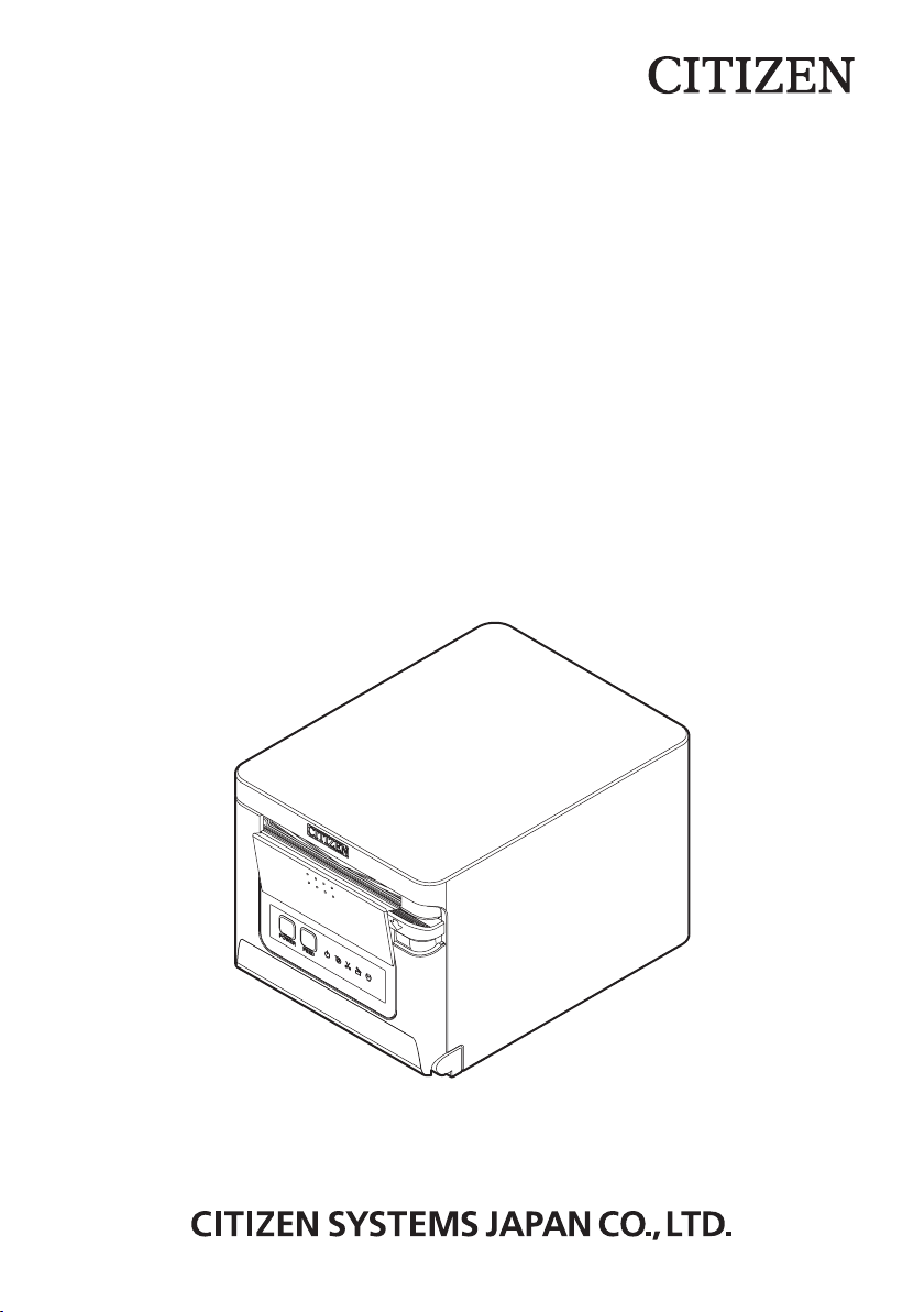
LINE THERMAL PRINTER
MODEL CT-S751
User’s Manual
Mode d’emploi
Benutzerhandbuch
Manuale dell’utente
Manual de Usuario
Page 2

WEEE MARK
If you want to dispose of this product, do not mix it with general household waste. There is a
En
separate collection systems for used electronics products in accordance with legislation under the
WEEE Directive and is effective only within European Union.
Wenn Sie dieses Produkt entsorgen wollen, dann tun Sie dies bitte nicht zusammen mit dem
Ge
Haushaltsmüll. Es gibt im Rahmen der WEEE-Direktive innerhalb der Europäischen Union gesetzliche Bestimmungen für separate Sammelsysteme für gebrauchte elektronische Geräte und
Produkte.
Si vous souhaitez vous débarrasser de cet appareil, ne le mettez pas à la poubelle avec vos
Fr
Ge
ordures ménagères. Il existe un système de récupération distinct pour les vieux appareils électroniques conformément à la législation WEEE sur le recyclage des déchets des équipements
électriques et électroniques qui est uniquement valable dans les pays de l’Union européenne.
Les appareils et les machines électriques et électroniques contiennent souvent des matières
dangereuses pour l’homme et l’environnement si vous les utilisez et vous vous en débarrassez de
façon inappropriée.
Si desea deshacerse de este producto, no lo mezcle con residuos domésticos de carácter general.
Fr
Ge
Sp
Existe un sistema de recogida selectiva de aparatos electrónicos usados, según establece la
legislación prevista por la sobre residuos de aparatos eléctricos y electrónicos (RAEE), vigente
únicamente en la Unión Europea.
Se desiderate gettare via questo prodotto, non mescolatelo ai riuti generici di casa. Esiste un
It
Fr
Ge
Sp
sistema di raccolta separato per i prodotti elettronici usati in conformità alla legislazione RAEE,
valida solo all’interno dell’Unione Europea.
Deponeer dit product niet bij het gewone huishoudelijk afval wanneer u het wilt verwijderen. Er
It
Fr
Du
Ge
Sp
bestaat ingevolge de WEEE-richtlijn een speciaal wettelijk voorgeschreven verzamelsysteem voor
gebruikte elektronische producten, welk alleen geldt binnen de Europese Unie.
Hvis du vil skille dig af med dette produkt, må du ikke smide det ud sammen med dit almindelige
It
Fr
Du
Da
Ge
Sp
husholdningsaffald. Der ndes et separat indsamlingssystem for udtjente elektroniske produkter i
overensstemmelse med lovgivningen under WEEE-direktivet, som kun er gældende i den Europæiske Union.
Se quiser deitar fora este produto, não o misture com o lixo comum. De acordo com a legislação
It
Por
Fr
Du
Da
Ge
Sp
que decorre da Directiva REEE – Resíduos de Equipamentos Eléctricos e Electrónicos, existe um
sistema de recolha separado para os equipamentos electrónicos fora de uso, em vigor apenas na
União Europeia.
Jeżeli zamierzasz pozbyć się tego produktu, nie wyrzucaj go razem ze zwykłymi domowymi
It
Por
Fr
Du
Pol
Da
Ge
Sp
odpadkami. Według dyrektywy WEEE obowiązującej w Unii Europejskiej dla używanych produktów
elektronicznych należy stosować oddzielne sposoby utylizacji.
——
2
Page 3

ENGLISH
——
3
Page 4

Compliance Statement for European Users
CE marking shows conformity to the following criteria and provisions:
Low Voltage Directive (2014/35/EU), EMC Directive (2014/30/EU), and RoHS directive (2011/65/EU)
Full text of the EU declaration of conformity is available at the following internet
address:
http://www.citizen-systems.co.jp/english/support/download/printer/others/eu_doc/
IMPORTANT: This equipment generates, uses, and can radiate radio frequencyenergy and if not installed and used in accordance with the instruction manual,
maycause interference to radio communications. It has been tested and found to
complywith the limits for a Class A computing device pursuant to Subpart J of Part
15 of FCCRules, which are designed to provide reasonable protection against such
interferencewhen operated in a commercial environment. Operation of this equipment in aresidential area is likely to cause interference, in which case the user at
his ownexpense will be required to take whatever measures may be necessary to
correct theinterference.
CAUTION: Use shielded cable for this equipment.
Sicherheitshinweis
Die Steckdose zum Anschluß dieses Druckers muß nahe dem Gerät angebracht
und leicht zugänglich sein.
For Uses in Canada
This Class A Information Technology Equipment (ITE) complies with Canadian CAN
ICES-3(A)/NMB-3(A).
This Information Technology Equipment (ITE) does not exceed the Class A limits
for radio noise emissions from digital apparatus set out in the Radio Interference
Regulations of the Canadian Department of Communications.
Pour L’utilisateurs Canadiens
Cet Equipements informatiques (EI) de la classe A est conforme a la norme CAN
ICES-3(A)/NMB-3(A) du Canada.
Le present Equipements informatiques (EI) n’emet pas de bruite radio electriques
depassant les limites applicables aux appareils numeriques de la classe A prescrites dans le Reglement sur le brouillage radioelectrique edicte par le ministere des
Communications du Canada.
——
4
Page 5

GENERAL PRECAUTIONS
Before using this product, be sure to read through this manual. After having read
this manual, keep it in a safe, readily accessible place for future reference.
The information contained herein is subject to change without prior notice.
Reproduction or transfer of part or all of this document in any means is prohib-
ited without permission from Citizen Systems.
Note that Citizen Systems is not responsible for any operation results regardless
of omissions, errors, or misprints in this manual.
Note that Citizen Systems is not responsible for any trouble caused as a result
of using options or consumables that are not specied in this manual.
Except explained elsewhere in this manual, do not attempt to service, disas-
semble, or repair this product.
Note that Citizen Systems is not responsible for any damage attributable to
incorrect operation/handling or improper operating environments that are not
specied in this manual.
Data is basically for temporary use and not stored for an extended period of time
or permanently. Please note that Citizen Systems is not responsible for damage
or lost prot resulting from the loss of data caused by accidents, repairs, tests or
other occurrences.
If you nd omissions, errors, or have questions, please contact your Citizen
Systems dealer.
If you nd any pages missing or out of order, contact your Citizen Systems
dealer for a replacement.
"Made for iPod," "Made for iPhone," and "Made for iPad" mean that an electronic
accessory has been designed to connect specically to iPod, iPhone, or iPad, respectively, and has been certied by the developer to meet Apple performance standards.
Apple is not responsible for the operation of this device or its compliance with safety
and regulatory standards.
Please note that the use of this accessory with iPod, iPhone or iPad may affect wireless performance.
——
5
Page 6

iPad, iPhone and iPod touch are trademarks of Apple Inc., registered in the U.S.
and other countries. iPad Air and iPad mini are trademarks of Apple Inc.
EPSON and ESC/POS are registered trademarks of Seiko Epson Corporation.
QR Code is a registered trademark of DENSO WAVE INCORPORATED.
Ethernet is a registered trademark of Fuji Xerox Corporation.
®
Bluetooth
is a registered trademark of Bluetooth-SIG Inc.
CITIZEN is a registered trademark of Citizen Watch Co., Ltd.
All other trademarks are the property of their respective owners.
Citizen Systems use these trademarks in accordance with the license of relevant
owners.
Copyright© CITIZEN SYSTEMS JAPAN CO., LTD. 2019
——
6
Page 7
SAFETY PRECAUTIONS...WHICH SHOULD BE STRICTLY
OBSERVED
Before using this product for the rst time, carefully read these SAFETY PRECAUTIONS. Improper handling may result in accidents (re, electric shock or injury).
In order to prevent injury to operators, third parties, or damage to property, special
warning symbols are used in the User’s Manual to indicate important items to be
strictly observed.
After having read this Manual, keep it in a safe, readily accessible place for future
reference.
Some of the descriptions contained in this manual may not be relevant to some
printer models.
The following describes the degree of hazard and damage that could occur if the
printer is improperly operated by ignoring the instructions indicated by the warning
symbols. Be sure to read this information carefully.
WARNING
Neglecting precautions indicated by this symbol may result in fatal or serious injury.
CAUTION
Neglecting precautions indicated by this symbol may result in injury or damage to property.
This symbol is used to alert your attention to important items.
This symbol is used to alert you to the danger of electric shock or electrostatic damage.
This symbol denotes a request to unplug the printer from the wall outlet.
This symbol is used to indicate that the power supply must be grounded.
This symbol is used to indicate useful information, such as procedures, instructions or the like.
This symbol is used to indicate prohibited actions.
——
7
Page 8
PRECAUTIONS ON PRINTER INSTALLATION
WARNING
Do not use or store this product in a place where it will be exposed to:
* Flames or moist air.
* Direct sunlight.
* Hot airow or radiation from a heating device.
* Salty air or corrosive gases.
* Ill-ventilated atmosphere.
* Chemical reactions in a laboratory.
* Airborne oil, steel particles, or dust.
* Static electricity or strong magnetic elds.
These locations create the risk of printer damage, as well as product fail-
ure, overheating, emission of smoke, re, or electric shock.
They can also result in re or electric shocks and so should always be
avoided.
Do not drop any foreign object nor spill liquid into the printer. Do not place
any object on the printer either.
Do not drop any metallic object such as paper clips, pins or screws into the
printer.
Do not place a ower vase, pot, or anything containing water on the print-
er.
Do not spill coffee, soft drinks, or any other liquid into the printer.
Do not spray insecticide or any other chemical liquid over the printer.
Dropping a metallic foreign object into the printer, may cause printer fail-
ure, re, or electric shock.
Should it occur, immediately turn the printer off, unplug it from the supply
outlet, and call your local Citizen Systems dealer.
Do not handle the printer in the following ways:
Do not subject the printer to strong impacts or hard jolts (e.g., being stepped on,
dropped or struck).
Never attempt to disassemble or modify the printer.
These actions create the risk of printer damage, as well as product failure,
overheating, emission of smoke, re, or electric shock.
They can also result in re or electric shocks and so should always be
avoided.
This device is not appropriate to be used where a child may be present.
Install, store, or use the device where it cannot be reached by a child.
Electric appliances could cause an unexpected injury or accident if they
are handled or used improperly.
Keep the power cord and signal cables out of the reach of children. Also
children should not be allowed to gain access to any internal part of the
printer.
The plastic bag the printer came in must be disposed of properly or kept
away from children. Wearing it over the head may lead to suffocation.
——
8
Page 9
CAUTION
Do not use the printer under the following conditions.
Avoid locations subject to vibration or instability.
Avoid locations where the printer is not level.
The printer may fall and cause an injury.
The quality of printing may deteriorate.
Do not obstruct the printer’s air vents.
Do not place anything on the printer.
Do not cover or wrap the printer in cloth or blankets.
Doing so could cause heat to build up and deform the case or start a re.
Avoid using the printer near a radio or TV set or from supplying it from the same
electric outlet as these appliances.
Avoid using the printer interconnected with a cable or cord that has no protection
against noise.
(For interconnections, use shielded or a twisted pair of cables and ferrite cores,
or other anti-noise devices.)
Avoid using the printer with a device that is a strong source of noise.
The printer may have an adverse effect on nearby radio or TV transmis-
sions. There may also be cases when nearby electrical appliances adverse-
ly inuence the printer, causing data errors or malfunction.
Installed in any orientation other than those specied.
Malfunction, failure, or electric shock may result.
Connect the printer to a ground.
Electric leakage may cause an electric shock.
Do not connect the printer’s ground to any of the following:
A gas explosion could result.
* Gas piping
* Telephone line ground
* Lightning rod
If lightning strikes a large surge of current may cause re or shock.
* Water pipes
Plastic water pipes should not be used for grounding. (Those approved by a
Waterworks Department may be used.)
Before connecting or disconnecting the grounding lead to or from the
printer, always unplug it from the electric outlet.
——
9
Page 10
PRECAUTIONS IN HANDLING THE PRINTER
WARNING
Please observe the following precautions for power source and power cord:
Do not plug or unplug the power cord with a wet hand.
Use the printer only at the specied supply voltage and frequency.
Use only the specied AC adapter with the printer.
Use only the power cord that comes with the printer, and never use the supplied
power cord with another device.
Check to make sure that the supply outlet from which the printer is powered has
a sufcient capacity.
Do not supply the printer from a power strip or current tap shared with other ap-
pliances.
Do not plug the power cord into an electric outlet with dust or debris left on the
plug.
Do not use a deformed or damaged power cord.
Do not move the printer while its power is on.
Neglecting to handle it properly may result in printer failure, emission of
smoke, re, or electric shock.
An overload may cause the power cord to overheat, catch re, or the circuit
breaker to trip.
Do not allow anything to rest on the power cord. Do not place the printer where
the power cord may be stepped on.
Do not subject the power cord to severe bending, twisting, or pulling. Do not
carry the product while it is in this state either.
Do not attempt to modify the power cord unnecessarily.
Do not place the power cord near any heating device.
Neglecting these cautions may cause wires or insulation to break, which
could result in electric leakage, electric shock, or printer failure.
If the power cord sustains damage, contact your Citizen Systems dealer.
Do not leave things around the electric outlet.
Supply power to the printer from a convenient electric outlet, readily accessible in
an emergency.
Pull the plug to immediately shut it down in an emergency.
Insert the power plug fully into the outlet.
If the printer will not be used for a long time, disconnect it from its electric outlet.
Hold the plug and connector when plugging or unplugging the power cord or
signal cable after turning off the printer and the appliance connected to it.
10
——
Page 11
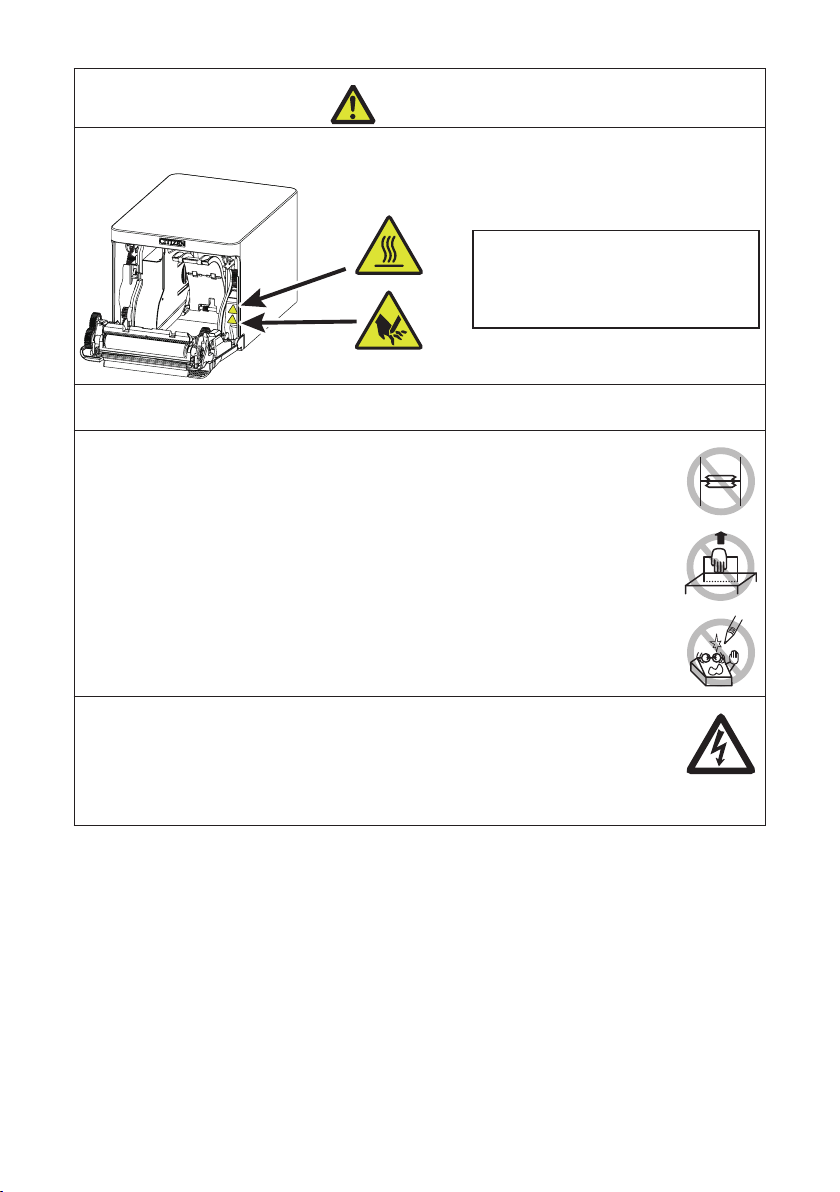
CAUTION
Caution label is attached in the position shown in the following gure. Carefully read the
handling precautions before using the printer.
These labels indicate that the head
becomes hot, so touching it may
cause burns, and touching the auto
cutter when opening the paper cover
may cause cuts on hands.
Do not transport this printer with the paper roll inside.
Printer failure or damage may occur.
To prevent possible malfunction or failure observe the following.
Do not open the paper cover during printing.
Avoid operating the printer without paper properly loaded.
Avoid the use of paper not complying with specications.
May result in poor print quality.
Avoid using torn pieces of paper or paper spliced with plastic adhesive tape.
Avoid forcibly pulling already loaded paper by hand.
Avoid using a sharp pointed device to operate panel buttons.
Be sure to rmly insert the cable plugs into their mating sockets.
A cross connection may damage the printer’s internal electronics or the
host system’s hardware.
Only use the printer with devices that have designated solenoid specications for
the cash drawer interface connector.
Neglecting this caution may result in malfunction or failure.
——
11
Page 12
To prevent injury and printer failures from worsening, observe the following:
Do not touch the printing surface of the thermal head.
Do not touch any of the moving parts (e.g., paper cutter, gears, active electric
parts) while the printer is working.
In case of trouble do not attempt to repair the printer. Ask Citizen Systems ser-
vice for repair.
Be careful that the covers do not pinch your hands or ngers.
Be careful of the sharp edges on the printer. Do not allow them to injure you or
damage property.
May result in electric shock, burn, or injury.
If the printer emits smoke, an odd smell, or unusual noise while
printing, immediately abort the current print session and
unplug the printer from the electric outlet.
DAILY MAINTENANCE
Observe the following precautions for daily maintenance.
When cleaning the printer, always turn it off and unplug it from the electric outlet.
Use a soft, dry cloth for cleaning the surface of the printer case.
For severe stains, use a soft cloth slightly dampened with water.
Never use organic cleaning solvent such as alcohol, paint thinner, trichloroethylene, benzene, or ketone. Never use a chemically processed cleaning cloth.
To remove paper dust, use a soft brush.
CAUTION
The thermal head is at a dangerously high temperature immediately after
printing.
Allow it to cool off before starting maintenance work.
——
12
Page 13

THE TABLE OF CONTENTS
1. GENERAL OUTLINE .....................................................................14
1.1 Features ............................................................................................14
1.2 Unpacking .........................................................................................15
1.3 Model Classication ..........................................................................16
1.4 Basic Specications ..........................................................................16
2. EXPLANATION OF PRINTER PARTS ...........................................18
2.1 Printer Appearance ...........................................................................18
2.2 Inside the Paper Cover ...................................................................... 20
2.3 Other Built-in Functions ..................................................................... 21
3. SETUP ............................................................................................23
3.1 Connecting the AC Power Cord ......................................................... 23
3.2 Serial Interface Board ........................................................................ 24
3.3 USB Interface ....................................................................................25
3.4 Bluetooth Interface Board .................................................................. 26
3.5 Bluetooth USB host interface board ..................................................29
3.6 Ethernet (LAN)/Wireless LAN Interface Board .................................. 35
3.7 USB Power Supply Port .....................................................................41
3.8 Connecting the Cash Drawer ............................................................43
3.9 Precautions for Installing the Printer .................................................45
3.10 Adjusting the Paper Near-end Sensor ............................................. 46
3.11 Loading Paper .................................................................................47
3.12 58-mm Width Roll Paper Partition ................................................... 49
3.13 Mounting the Cable Cover ...............................................................50
3.14 Precautions for Creating Applications and Practical Operations .....51
3.15 Download Site for Various Electronic Files ...................................... 51
4. MAINTENANCE AND TROUBLESHOOTING ...............................52
4.1 Periodic Cleaning ..............................................................................52
4.2 Clearing a Cutter Error ...................................................................... 53
4.3 Self Test ............................................................................................. 54
4.4 Hexadecimal Dump Printing .............................................................. 55
4.5 Error Indications ................................................................................56
4.6 Paper Jams .......................................................................................58
4.7 Precautions for Performing Printing for Which
Printing Speed Changes ...................................................................58
5. OTHER ...........................................................................................59
5.1 External Views and Dimensions ........................................................59
5.2 Printing Paper .................................................................................... 60
5.3 Manual Setting of Memory Switches ................................................. 61
——
13
Page 14

1. GENERAL OUTLINE
The CT-S751 line thermal printer series is designed for use with a broad array of terminal equipment including data, POS, and kitchen terminals.
These printers have extensive features so they can be used in a wide range of applications.
1.1 Features
High-speed printing at up to 350 mm/sec possible
Stylish design
Compact size with the lowest possible height
The front paper eject structure enables use where the height is restricted
Compliant with IPX1 for drip-proof capabilities *
Support for paper widths of 80 mm and 58 mm
High-speed cutter employed
USB interface included as standard
Equipped with a standard USB power supply port
Interchangeable interface board
XML/Web print function included (wired LAN or wireless LAN model)
USB host function capable of controlling peripheral devices included (wired LAN or
Bluetooth USB host model)
Printer status and errors indicated by ve LEDs
Built-in drawer kick interface
USB-linked power OFF function available
16 level greyscale and clear printing
Paper saving function available
Support for the JIS X0213 third and fourth level Kanji character sets
Support for the simplied and traditional Chinese character sets and Hangul char-
acter set
Support for UTF-8 using commands
Various customizations using the memory switches possible
User created characters and logos can be saved in the user memory
Support for barcodes including 2D barcodes
Apple MFi certied Bluetooth communication support (Bluetooth model)
*: The product has been checked to determine that vertically falling drops of water will have no harmful effect,
but the product is not guaranteed to be completely drip-proof.
14
——
Page 15
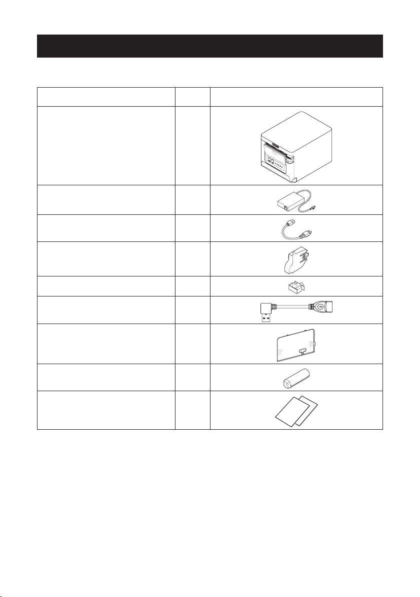
1.2 Unpacking
Make sure the following items are included with your printer.
NAME
Printer 1
AC Adapter (37AD5) 1
AC power cord 1
Partition 1
Cable clamp *1 1
L-shaped USB cable *2 1
QUAN-
TITY
ILLUSTRATION
Cable cover 1
Sample paper roll 1 roll
Quick Start Guide 2
*1: Provided with the RS model
*2: Included with the HBT model
15
——
Page 16

1.3 Model Classication
34
Model numbers indicate printer features according to the following system.
CT - S751 RS E- BK
12
1. Model name
2. Interface
RS: Serial RS-232C+USB
ET: Ethernet+USB
HET: Ethernet (USB host function) + USB
BT: Bluetooth+USB
HBT: Bluetooth (USB host function)
WF: Wireless LAN+Ethernet+USB
NN: USB
3. Market
U: North America
E: Europe
I: India
4. Body case color
WH: Pure white
BK: Black
Contact us in advance for special combinations, some of which may not be available.
1.4 Basic Specications
Item Specications
Model CT-S751
Print method Line thermal dot print method
Print widths 72 mm/576 dots, 68.25 mm/546 dots, 64 mm/512 dots, 52.5 mm/420 dots, 48.75 m/390
Dot density 8 × 8 dots/mm (203 dpi)
Print Speed 350 mm/sec (maximum speed, print density level 100%, 2800 dot lines/sec)
Number of print
columns *1
Character size *2 Font A:1.50×3.00 mm, Font B:1.13×3.00 mm, Font C:1.00×2.00 mm
dots, 48 mm/384 dots, 45 mm/360 dots, factory default 72 mm
Font Maximum number
Font A 48 35 12 × 24
Font B 64 46 9 × 24
Font C 72 52 8 × 16
of characters
(columns) / 80 mm
16
Maximum number
of characters
(columns) / 58 mm
——
Dot conguration
(dots)
Page 17

Item Specications
Character type Alphanumeric characters, international characters, PC437/850/852/857/858/860/863/86
User memory 384 KB (capable of storing user-dened characters and logos)
Bar code types UPC-A/E, JAN(EAN) 13 digits/8 digits, ITF, CODE39, CODE128, CODABAR (NW-7),
Line spacing 4.25 mm (1/6 inch) (Variable by command)
Paper roll Roll paper: 80 mm x max. ø83 mm
Interface Serial (RS-232C standard), USB, Bluetooth+USB, LAN, wireless LAN+LAN, LAN (USB
Ethernet 100BASE-TX/10BASE-T
Wireless LAN IEEE802.11n, IEEE802.11a, IEEE802.11g, IEEE802.11b
Bluetooth Version: Bluetooth 3.0 + EDR
USB power supply
port
Cash drawer kickout
Input buffer 4 K bytes/45 bytes
Supply voltage DC 24 V ±5%
Power consumption Approximately 50 W (average), 2 W or less (standby), 0.2 W or less (USB-linked power
AC Adapter
(37AD5)
Weight Approximately 1.3 kg
Outside dimensions 125 (W) × 165 (D) × 108 (H) mm
Operating tempera-
ture and humidity
Storage temperature
and humidity
Reliability Print head life: 200 km, 200 million pulses (room temperature, room humidity, specied
Safety standard *3 UL, C-UL, FCC Class A, CE Marking
4/865/866, WPC1252, WPC1258, Katakana, ThaiCode 11/18 (1Pass/3Pass), TCVN-3,
Kanji (JIS rst, second, third, and fourth level), Kana, extended characters, JIS X0213,
GB18030, BIG5, KS Hangul, EUC Hangul
CODE93, PDF417, QR Code, GS1-DataBar
Paper thickness: 53 to 85 μm (paper roll inner diameter 12 mm / outer diameter 18 mm)
host function) (USB 2 port)), Bluetooth (USB host function) (USB 2 port))
Prole: SPP (Serial Port Protocol), iAP (iPod Accessory Protocol)
Power class: Class2
Max. 2.1 A
Supports 2 cash drawers
OFF state)
Rated input: AC 100 to 240 V, 50/60 Hz, 150 VA
Rated output: DC 24 V, 2.1 A
5 to 45°C, 10 to 90% RH (no condensation)
-20 to 60°C, 10 to 90% RH (no condensation)
recommended paper, specied paper thickness), Auto cutter life: 2 million cuts (3-inch),
1.5 million cuts (2-inch) (room temperature, room humidity, specied recommended
paper, specied paper thickness)
Notes:
*1: The number of printable columns is selected using a memory switch.
The numbers of columns noted in this table refer to typical models. The number of
columns varies depending on specications.
*2: Characters appear small because the dimensions include a blank area surrounding
each character.
*3: This standard applies when our AC Adapter (37AD5) is used.
——
17
Page 18
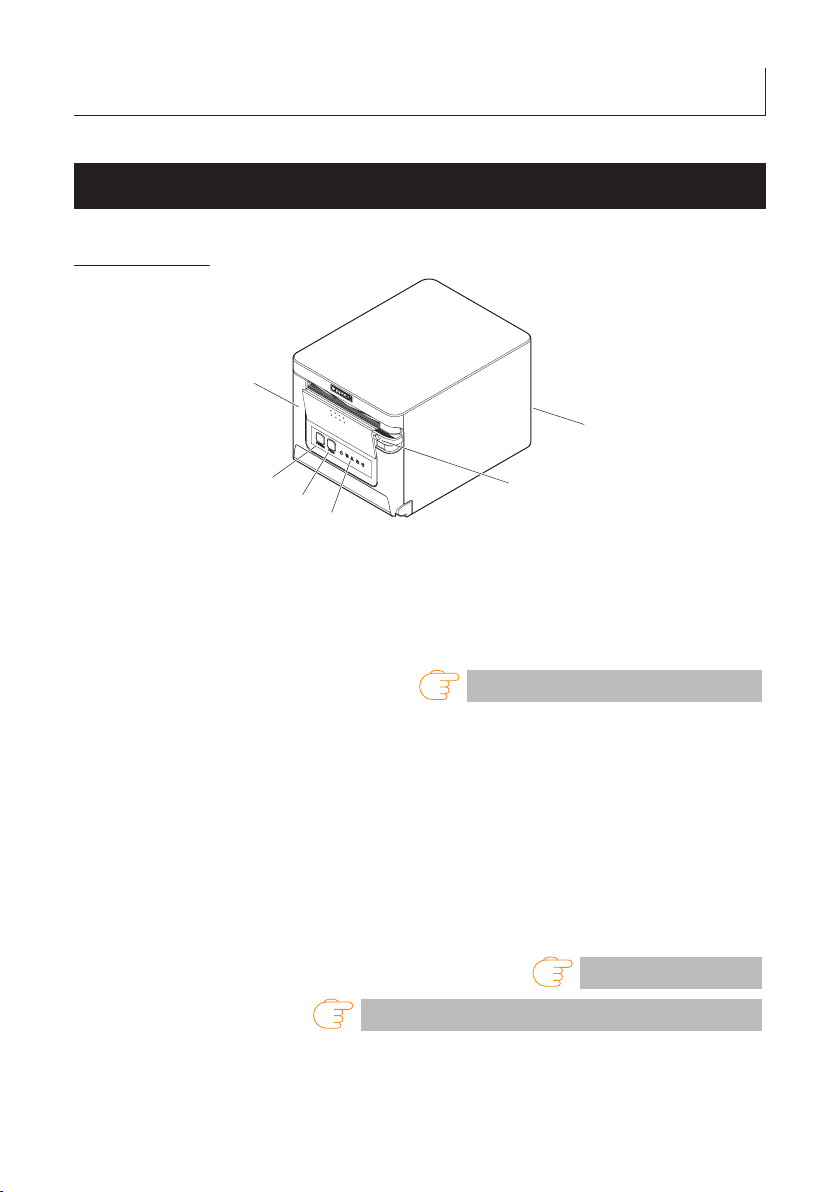
2. EXPLANATION OF PRINTER PARTS
1
5
6
2.1 Printer Appearance
Names of parts
3
2
4
1. Paper cover
Open to load paper.
Also open to clear a cutter error.
* The paper cover cannot be used for manual cutting.
Refer to 4.2 Clearing a Cutter Error
2. Cover open lever
Use to open the paper cover.
3. POWER button
Hold down two or three seconds to switch power on or off.
4. FEED button
Press this button to feed paper.
In case of a cutter error, press the FEED button with the paper cover closed after
removing the cause.
The printer enters the mode for setting memory switches and running self test.
Refer to 4.3 Self Test
5. Operation panel
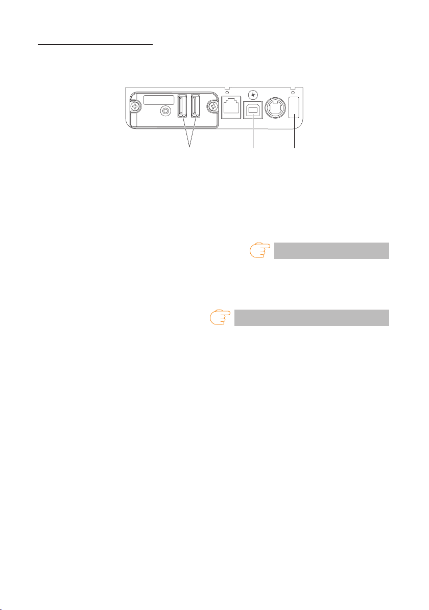
6. Rear connectors
Refer to 5.3 Manual Setting of Memory Switches
——
18
Page 19
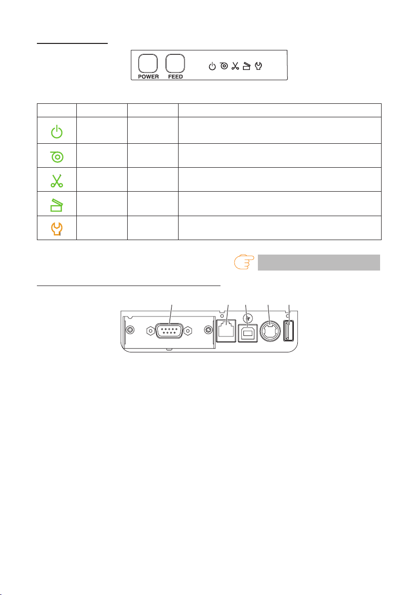
Operation panel
352 41
RS: Serial RS-232C + USB
The operation panel has ve LEDs and two buttons.
LED name Color Description
POWER LED Green Lights when the power is on, turns off when the power is off.
PAPER LED Green
CUTTER LED Green
COVER LED Green
SERVICE LED Orange Flashes when an unrecoverable printer abnormality is detected.
Lights or ashes when no paper or low paper is detected.
May also light or ash when other abnormalities are detected.
Flashes when a cutter error is detected.
May also light or ash when other abnormalities are detected.
Lights or ashes when an open paper cover is detected.
May also light or ash when other abnormalities are detected.
Rear connectors (serial interface example)
1. Interface connector (serial, USB, etc.)
Connect to the interface cable.
2. Cash drawer kick-out connector
Connect to the cable from the cash drawer.
Refer to 4.5 Error Indications
3. Power connector
Connect to the AC adapter cable.
4. USB connector
5. USB power supply port
Supply power to a USB device.
19
——
Page 20
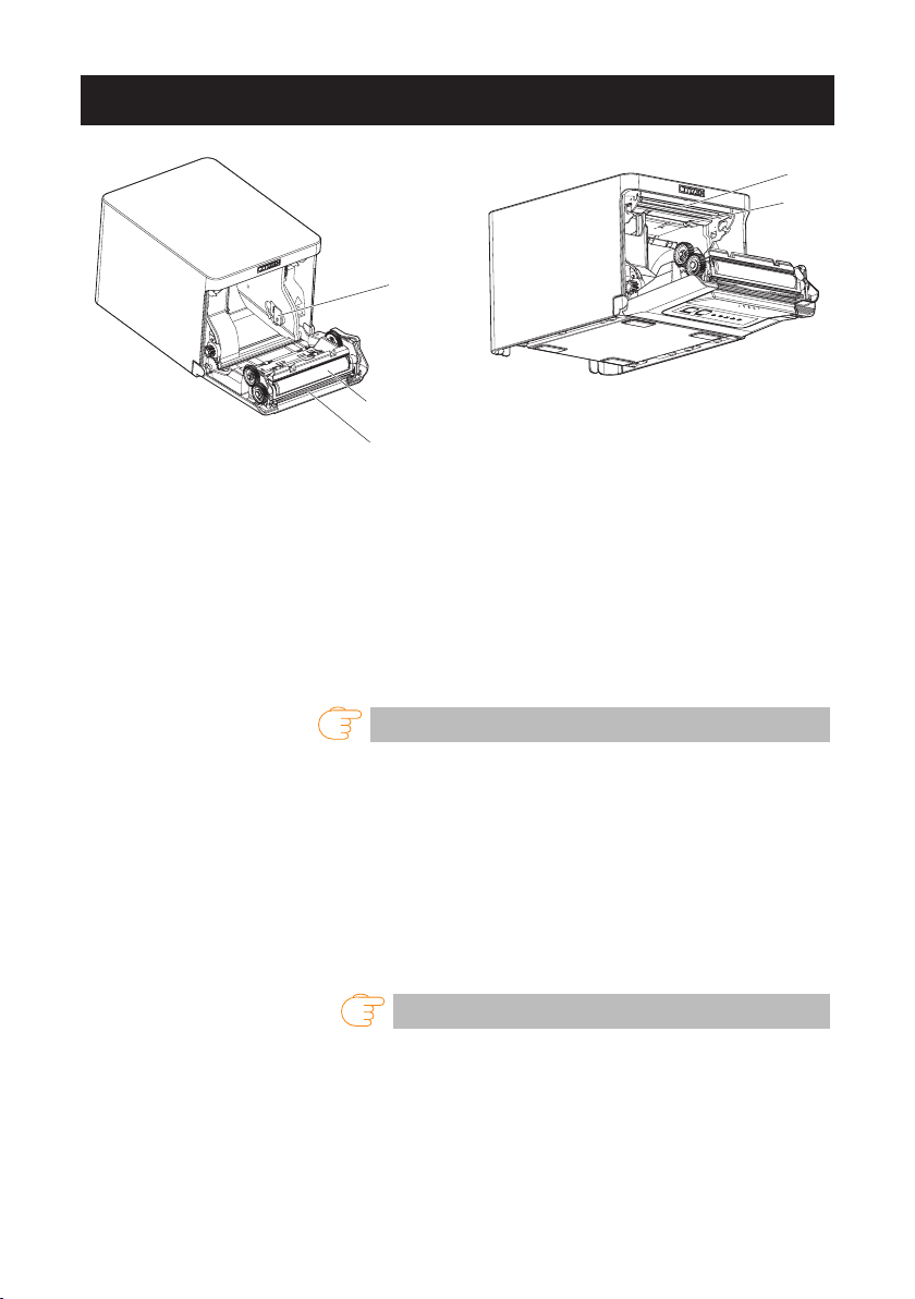
2.2 Inside the Paper Cover
1
6
2, 3
5
1. Print head (thermal)
Prints characters and graphic data on paper (paper rolls).
2. Paper near-end (PNE) sensor
Detects when the paper is near the end of the roll. Adjust the position of the sensor
to determine when it detects the end of the paper is near.
3. Button to change paper near-end sensor
Change the position of the paper near-end sensor to match the paper being used.
Refer to 3.10 Adjusting the Paper Near-end Sensor
4
4. Paper end (PE) sensor
Detects when there is no paper. Printing stops when this sensor detects there is no
paper.
5. Platen
Feeds the paper.
Do not remove the platen except to do maintenance.
6. Auto cutter
Cuts the paper.
Refer to 5.3 Manual Setting of Memory Switches
——
20
Page 21

2.3 Other Built-in Functions
Buzzer
Buzzes when errors occur or when operations or command operations are
performed.
Refer to 4.5 Error Indications
User memory
You can save user-dened logo and character data in this memory. Data remains
stored in this memory even if the printer is turned off. For information on how to
save data, refer to the Command Reference.
Memory switch
Setting of various kinds of functions can be stored in memory. Settings remain
stored in the memory even if the printer is turned off.
USB-linked power OFF (When MSW6-3 of memory switch is set to ON)
When the printer is connected to PC by USB, the printer becomes the state of USB-
linked power OFF after 3 seconds when PC power off or USB connection lost.
This mode is canceled when the PC is turned back on or when a USB connection is
established.
CAUTION
Since the POWER LED is unlit when the state of USB-linked power OFF, it cannot be identi-
ed from the power OFF.
Pressing the POWER button while the state of USB-linked power OFF turns on power nor-
mally.
21
——
Page 22

Paper saving functions
Memory switches MSW8-3 through MSW8-4 can be used to congure the settings
below, which save paper.
Top margin suppression
The printer back feeds the paper before printing which reduces the blank space
at the top edge of the paper.
The back feed amount can be specied.
Line gap reduce
Automatically compresses the linefeed amount between lines. The compression
ratio can be specied.
CAUTION
Remove the partially cut paper before performing back feed for starting printing.
The cut paper may be torn off in the next printing process, which may cause a problem.
Auto side shift (MSW8-6)
This function dissipates heat load during frequent heat generation by a vertical
ruled line or other specic head heating element.
If no data is received within 15 seconds after each cut or print, the print position is
automatically slid N* dots to the right. The original print position is returned to at the
next slide timing.
* N is the MSW8-6 setting value.
CAUTION
If the right margin is too narrow, this may result in some print characters being cut off.
This function is disabled under initial settings.
To enable this function, use MSW8-6 to specify an appropriate value for the maximum slide
amount.
——
22
Page 23
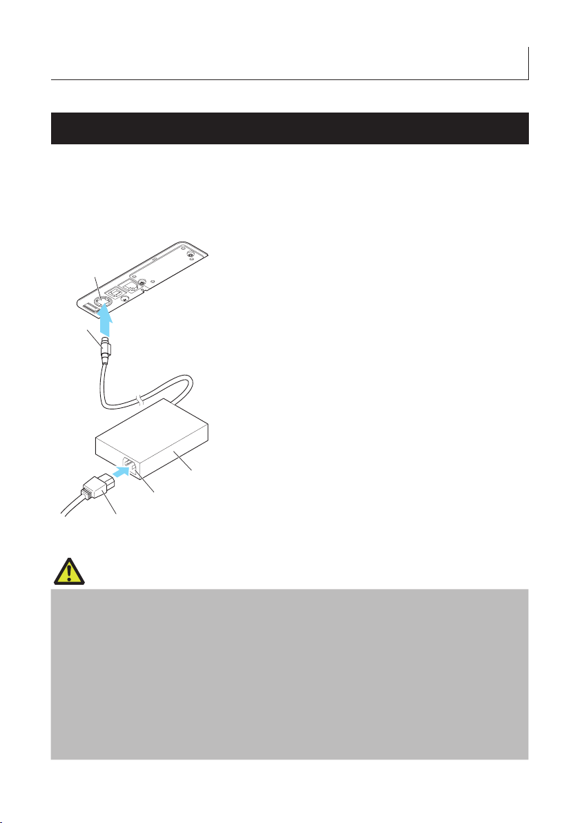
3. SETUP
5
3.1 Connecting the AC Power Cord
1. Turn off the power.
2. Connect the power connector to the AC adapter cable connector.
Next, connect the AC power cord to the AC inlet, and insert the plug into an electric
outlet.
2
1
1. Cable connector
2. Power connector
3. AC adapter
4. AC inlet
5. AC power cord
3
4
CAUTION
Use only the specied AC adapter.
Always hold the AC adapter’s cable connector by the connector when removing or inserting it.
Use an AC power source that does not also supply power to equipment that generates elec-
tromagnetic noise.
Pulling on the AC power cord may damage it, cause a re, electric shock, or break a wire.
If a lightning storm is approaching, unplug the AC power cord from the electric outlet. A light-
ning strike may cause a re or electric shock.
Keep the AC power cord away from heat generating appliances. The insulation on the AC
power cord may melt and cause a re or electric shock.
If the printer is not going to be used for a long time, unplug the AC power cord from the elec-
tric outlet.
Place the AC power cord so that people do not trip on it.
——
23
Page 24
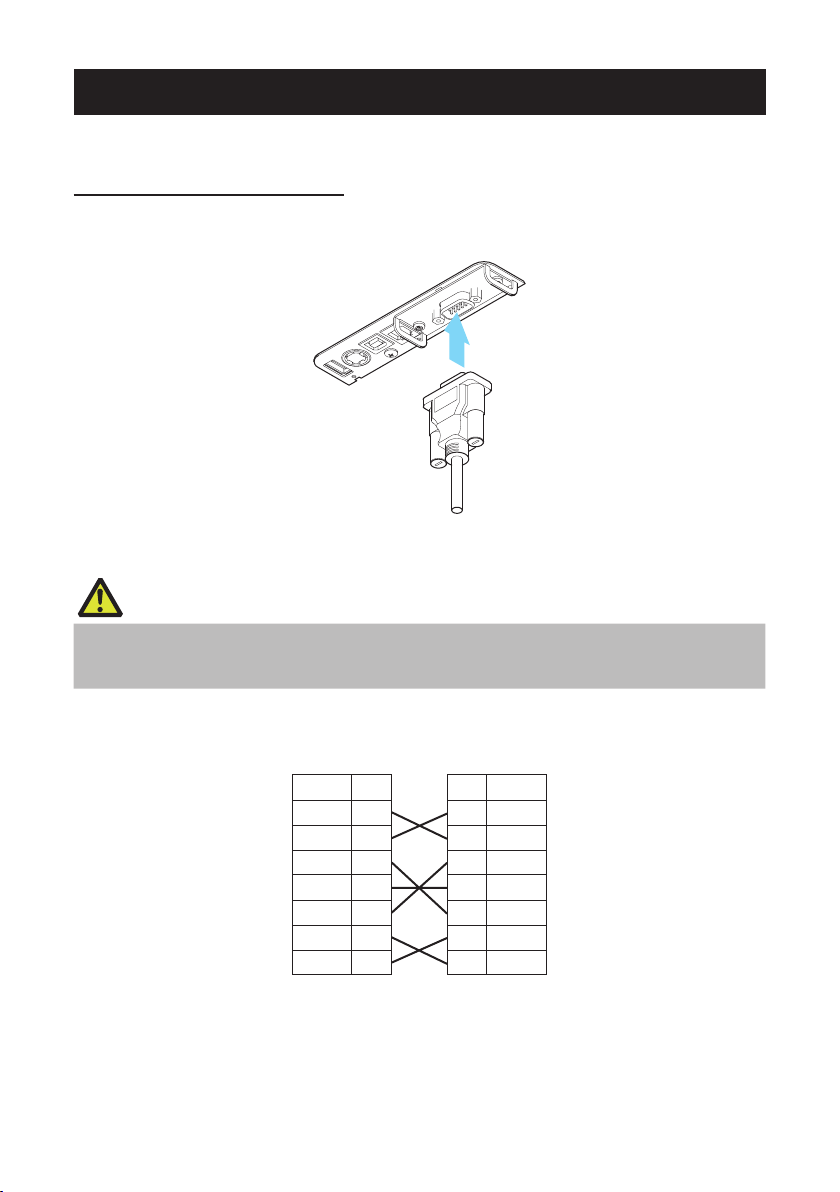
3.2 Serial Interface Board
PrinterPC
Data can be exchanged by serial communication.
Connecting the Interface Cable
1. Turn off the power.
2. Conrm the orientation of the interface cable and connect it to the port.
3. Insert the other connector rmly into the interface port of the host computer.
CAUTION
When disconnecting the cable, always hold the connector.
Place the interface cable so that people do not trip on it.
Do not connect multiple interfaces at the same time.
Use a serial cable with the connection layout shown below.
9-pin (female) - 9-pin (female) cable
Signal Pin Pin Signal
RXD 2 2 RXD
TXD 3 3 TXD
DTR 4 4 DTR
SG 5 5 SG
DSR 6 6 DSR
RTS 7 7 RTS
CTS 8 8 CTS
——
24
Page 25
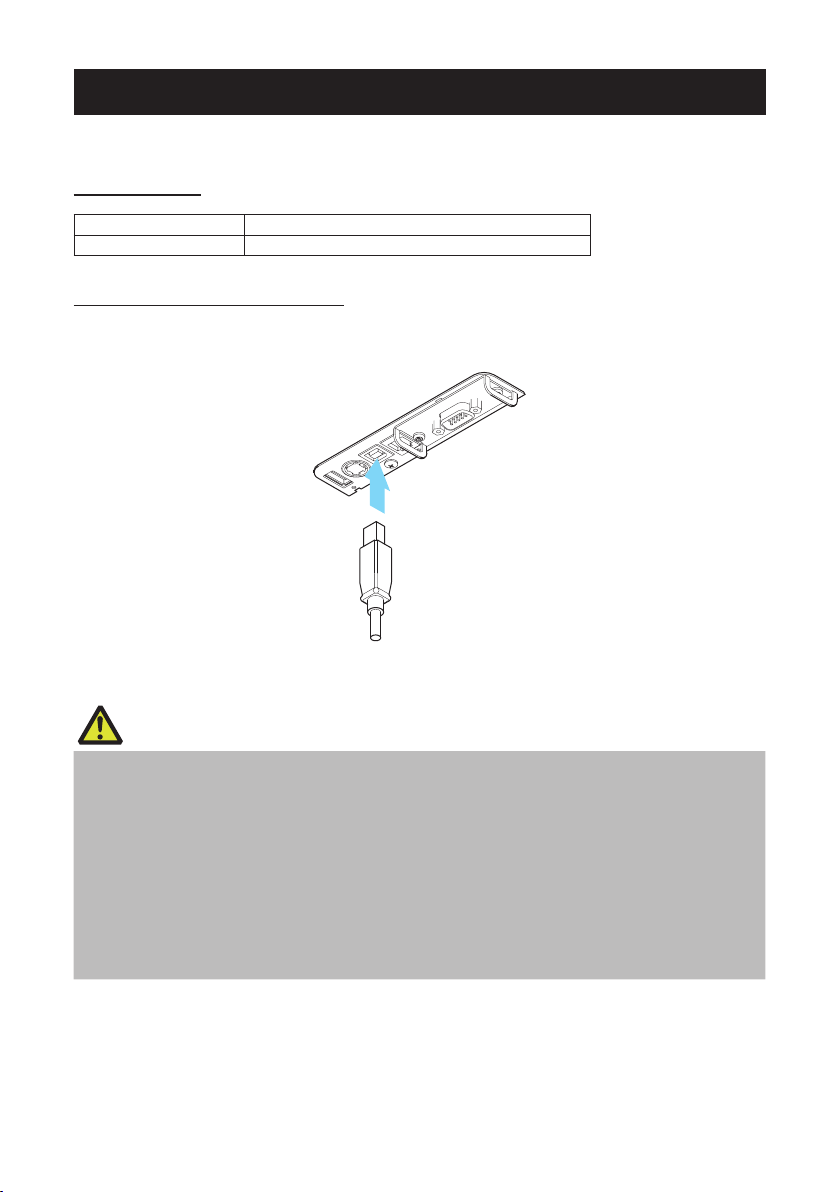
3.3 USB Interface
Data can be exchanged by USB communication.
Specifications
Standard USB 2.0 specication-compliant
Communication speed Supports 12 Mbps (Full-Speed) transfer
Connecting the Interface Cable
1. Turn off the power.
2. Conrm the orientation of the interface cable and connect it to the port.
3. Insert the other connector rmly into the interface port of the host computer.
CAUTION
When disconnecting the cable, always hold the connector.
Place the interface cable so that people do not trip on it.
Do not connect multiple interfaces at the same time.
Be careful not to insert the USB cable into the cash drawer kick-out connector.
To connect more than one printer to a single computer by USB, you must change the serial
number of the USB interface.
There are models with a USB port on the interface board side.
With such a model, do not connect USB cables to both the printer main unit side and interface
board side.
If USB cables are connected to both, priority will be given to communication of the one connected to the port on the main unit side.
——
25
Page 26
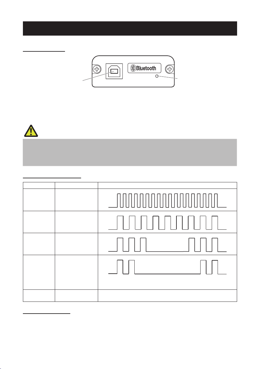
3.4 Bluetooth Interface Board
1
2
Names of parts
1. Status LED
The Bluetooth communication/connection/error status is indicated by this LED.
2. USB connector
Data can be exchanged by USB communication.
CAUTION
When using this interface board as a USB interface, do not connect USB cables to both the main
unit side and interface board side.
If USB cables are connected to both, priority will be given to communication of the one connected to the connector on the main unit side.
Bluetooth status LED
Status Description LED Status
Detection
standby
(Discoverable)
Standing by for
detection and
connection
Connection
standby
(Connectable)
iOS connection Data session un-
Communicating
Error Error or settings be-
Standing by for
connection
opened
iOS: data session
opened
Other OS: connection established and
communication in
progress
Unlit
ing congured
Pairing operation
You need to perform the operations below the rst time you establish a Bluetooth connection for Bluetooth data communication.
1. Detect Bluetooth devices
2. Congure pairing settings
——
26
Page 27

1. Detecting Bluetooth devices
Conrm that Bluetooth is enabled on the host PC before searching for Bluetooth
devices.
This product will show up as "CT-S751_XX"(XX is last 2 digits of unique BD
address.) when it is detected.
Select this product from among the detected devices.
Note: You can search for devices and change the names.
When memory switch MSW13-5 is set to "No Response," nothing is displayed by
device detection.
You can temporarily switch this setting to device detection (detect mode) by opening
the paper cover and holding down the FEED button for two seconds. Detect mode
is exited when the connection between the host PC is terminated.
2. Conguring pairing settings
Normally, selecting the printer during device detection will transition directly to
pairing settings.
CAUTION
Some host PC congurations and models may not transition directly to pairing settings after the
printer is selected during device detection.
The operation required to congure pairing settings depends on whether SSP (secure
simple pairing) is enabled on the host PC.
If SSP is enabled on the host PC, pairing can be achieved without additional operations.
If SSP is disabled on the host PC, you will be prompted to input a passkey.
Input the passkey as described below.
Passkey
Last four digits of the address on the self test printout (Letters A through F are uppercase)
Example: If the address is 01:23:45:67:89:AB the passkey is 89AB.
If you delete paring information from the host PC without deleting the corresponding
pairing information on the printer, the printer may not show up if you detect devices
again with the host PC.
To delete printer pairing information, open the paper cover and then hold down the
FEED button for ve seconds.
Deleting pairing information on the printer will put the printer into discovery mode.
Auto reconnection
With iOS device Bluetooth communication, a connection between a paired iOS device
and the printer is not automatically restored after it is lost. However, when auto reconnection is enabled, the printer tries to reconnect with an iOS device after two-way communication is enabled and automatically restores the connection.
——
27
Page 28

CAUTION
This function is enabled when shipped from the factory. (MSW13-6)
Auto reconnection can take some time to connect when the host is not an iOS device.
Even if the partner device is an iOS device, the conditions below can interfere with the auto
reconnection function.
When you want Bluetooth communication to cut off after printing is complete
When there are multiple iOS devices printing on the same printer
Under such conditions, disable auto reconnection.
Enabling and disabling auto reconnect
During self test, press the FEED button 3 times -> Auto reconnect = Valid
During self test, press the FEED button 4 times -> Auto reconnect = Invalid
At the end of self test, new setting will be printed as Auto reconnect [Valid] or [Invalid].
Refer to 4.3 Self Test
28
——
Page 29
3.5 Bluetooth USB host interface board
In addition to printer control via Bluetooth communication, Bluetooth USB host interfaces can control peripheral devices connected via a USB port.
Connecting a Peripheral Device
1. Turn off the power.
2. Connect the cable of a peripheral device to this port.
CAUTION
A peripheral device cannot be controlled if it is connected to the USB power supply port.
Be sure to connect it to the USB port of the interface board.
29
——
Page 30
Connecting a USB Device
123
The function assigned to each USB port differs.
Connect the USB device to be connected to the correct place in reference to the fol-
lowing gure.
1. For peripheral device control
Connect a peripheral device.
The connected peripheral device can be controlled.
2. For host computer communication
Connect with a host computer.
The printer and host computer will communicate via USB.
Refer to 3.3 USB Interface
3. For supplying power
Connect a mobile device or other USB device.
Power can be supplied to a connected USB device.
* This port does not support USB data communication.
Refer to 3.7 USB Power Supply Port
30
——
Page 31

Names of parts
12
1. Panel button
Control this interface board.
2. USB 2 port
Connect a peripheral device.
CAUTION
Only connect peripheral devices specied by our company to the USB port.
Only plug in/remove peripheral devices when the printer power is turned off.
Pairing operation
You need to perform the operations below the rst time you establish a Bluetooth connection for Bluetooth data communication.
1. Detect Bluetooth devices
2. Congure pairing settings
1. Detecting Bluetooth devices
Conrm that Bluetooth is enabled on the host PC before searching for Bluetooth
devices.
This product will show up as "CT-S751_XX"(XX is last 2 digits of unique BD
address.) when it is detected.
Select this product from among the detected devices.
Note: You can search for devices and change the names.
When memory switch MSW13-5 is set to "No Response," nothing is displayed by
device detection.
With these settings, pressing and holding the panel button for at least three
seconds and then pressing it twice more places the product temporarily in a state
where it will be found in device searching (discovery mode).
Discovery mode cancels when the product is connected to a host PC.
——
31
Page 32

2. Conguring pairing settings
Normally, selecting the printer during device detection will transition directly to
pairing settings.
CAUTION
Some host PC congurations and models may not transition directly to pairing settings after the
printer is selected during device detection.
The operation required to congure pairing settings depends on whether SSP (secure
simple pairing) is enabled on the host PC.
If SSP is enabled on the host PC, pairing can be achieved without additional operations.
If SSP is disabled on the host PC, you will be prompted to input a passkey.
Input the passkey as described below.
Passkey
Last four digits of the address on the self test printout (Letters A through F are uppercase)
Example: If the address is 01:23:45:67:89:AB the passkey is 89AB.
If you delete paring information from the host PC without deleting the corresponding
pairing information on the printer, the printer may not show up if you detect devices
again with the host PC.
When deleting pairing information, press and hold the panel button for at least three
seconds, and after the buzzer sounds, press it four more times.
If successful, “Erase Bonded Device” is printed.
Deleting pairing information on the printer will put the printer into discovery mode.
Auto reconnection
With iOS device Bluetooth communication, a connection between a paired iOS device
and the printer is not automatically restored after it is lost. However, when auto reconnection is enabled, the printer tries to reconnect with an iOS device after two-way communication is enabled and automatically restores the connection.
CAUTION
This function is enabled when shipped from the factory. (MSW13-6)
Auto reconnection can take some time to connect when the host is not an iOS device.
Even if the partner device is an iOS device, the conditions below can interfere with the auto
reconnection function.
When you want Bluetooth communication to cut off after printing is complete
When there are multiple iOS devices printing on the same printer
Under such conditions, disable auto reconnection.
——
32
Page 33

Enabling and disabling auto reconnect
Panel button USB port
During self test, press the FEED button 3 times -> Auto reconnect = Valid
During self test, press the FEED button 4 times -> Auto reconnect = Invalid
At the end of self test, new setting will be printed as Auto reconnect [Valid] or [Invalid].
Refer to 4.3 Self Test
Panel button operation
Use the panel button on the rear of the Bluetooth board to operate this board.
BT device search (MSW13-5) settings
1. Press and hold the panel button to turn on printer power.
2. Press the panel button within one second after starting the printer.
The setting changes in accordance with the number of times you press the panel
button.
Two presses: Discovery possible
Three presses: No response
After these operations the printer restarts.
33
——
Page 34

Print the interface board state
After starting the printer, pressing the panel button once prints the interface board
state.
Print example
1. Board rmware version
2. Address of equipped Bluetooth module
3. Bluetooth name
4. Response prole in Bluetooth transmission
5. Bluetooth setting state
6. Name of connected USB device (“No connection” is displayed when there is no
connection)
7. Board status
——
34
Page 35

3.6 Ethernet (LAN)/Wireless LAN Interface Board
This section provides an overview of the interface board. For details on this board, including explanations about the USB host function and XML peripheral device support,
refer to the separate manual.
Connecting the Interface Cable
1. Turn off the power.
2. Conrm the orientation of the interface cable and connect it to the port.
3. Connect the other connector to a hub, router, or similar device.
CAUTION
When disconnecting the cable, always hold the connector.
Place the interface cable so that people do not trip on it.
Do not connect multiple interfaces at the same time.
Hold the connector of the LAN cable perpendicular and straight when connecting or discon-
necting it. Doing it at an angle may cause the connector to misconnect.
35
——
Page 36

Connecting a Peripheral Device
12
USB host model
1. Turn off the power.
2. Connect the cable of a peripheral device to this port.
CAUTION
A peripheral device cannot be controlled if it is connected to the USB power supply port.
Be sure to connect it to the USB port of the interface board.
Connecting a USB Device
The function assigned to each USB port differs.
Connect the USB device to be connected to the correct place in reference to the fol-
lowing gure.
3
Ethernet
1. For peripheral device control
Connect a peripheral device.
The connected peripheral device can be controlled.
2. For host computer communication
Connect with a host computer.
The printer and host computer will communicate via USB.
36
4
Wireless LAN
Refer to 3.3 USB Interface
——
Page 37

3. For supplying power
Panel buttonPanel button
Panel button
USB host model
Connect a mobile device or other USB device.
Power can be supplied to a connected USB device.
* This port does not support USB data communication.
Refer to 3.7 USB Power Supply Port
4. For wireless LAN adapter connection
Connect a wireless LAN adapter.
Panel button operation
Board operations are performed using the panel button on the rear of the LAN board.
Wireless LANEthernet
Ethernet
Enabling LAN connection
Turn on the printer. Operation of this board will start about 20 seconds later.
Printing LAN setup information
Press the panel button.
Entering setting mode
Hold down the panel button. A buzzer* will sound once to indicate that setting mode
has been entered.
You can use setting mode to read factory settings.
If no operation is performed for 3 seconds in conguration mode, the mode
switches back to normal mode.
Returning to factory settings
Enter the board setting mode, and then hold down the panel button. This returns the
board to its factory settings.
CAUTION
The board will automatically restart after this operation is complete. After clearing settings, you
will need to re-congure network settings.
——
37
Page 38

LED Functions
USB host model
The tables below explain how to interpret LED indications.
12 3 12 312 3
Wireless LANEthernet Ethernet
1. Wired LAN transmission speed
Transmission speed LED (green)
100 Mbps Lit
10 Mbps/Not connected Unlit
2. Wired LAN connection/transmission status
Connection status LED (yellow)
Connected Lit
Not connected Unlit
Data transmission in
progress
3. Wired/Wireless LAN status
Connection status LED (green) LED (red) Description
No printer connection Unlit — Board is not connected with a printer.
Printer
connection
No network connection
Connected by wired
LAN
Wired LAN operation Lit Lit Network operation being performed over
Connected by wireless LAN *
Wireless LAN operation *
Resource error Alternate ashing
System error Alternate ashing
Flashing
Lit Unlit Board is connected with a printer.
Lit Flashing
Flashing
(2-second
cycle)
Flashing
(2-second
cycle)
(1-second cycle)
(0.2-second cycle)
(1-second
(1-second
cycle)
Flashing
cycle)
Lit Network operation being performed over
Getting an IP address from the DHCP
server over wired LAN.
wired LAN.
Connecting to an access point or getting
an IP address from the DHCP server over
wireless LAN.
wireless LAN.
Board is unable to operate normally.
Board is unable to operate normally.
*: Only when using wireless LAN
38
——
Page 39

Web Manager
The interface board has a Web Manager function that can be used to connect to the
board with a web browser and change board settings.
Starting up Web Manager
1. Start up a web browser.
2. In the address eld, input the board's IP address and then press [Enter].
HOME Screen
This is the Web manager home screen.
The following screen is an example for a wireless LAN.
Here, press the [CONFIG] button.
39
——
Page 40

CONFIG Screen
This will display the Login dialog box shown below. Log in as an administrator and then
congure interface board settings.
User Name
Input a board administrator user name. (Initial setting: admin)
Password
Input the administrator user password. (Initial setting: admin)
[Login] button
After inputting an administrator user name and password, click the [Login] button.
This displays the setting screen.
For details about settings, refer to the separate manual.
40
——
Page 41

3.7 USB Power Supply Port
123
Power (max. 2.1 A) can be supplied to a mobile device or other USB device by connecting the cable of the USB device to the power supply port.
Connecting Mobile Device or Other Device
1. Turn off the power.
2. Connect the cable of a mobile device or other device to the USB power supply port.
Connecting a USB Device
The function assigned to each USB port differs.
Connect the USB device to be connected to the correct place in reference to the fol-
lowing gure.
1. For peripheral device control
Connect a peripheral device.
The connected peripheral device can be controlled.
2. For host computer communication
Connect with a host computer.
The printer and host computer will communicate via USB.
41
Refer to 3.3 USB Interface
——
Page 42

3. For supplying power
Connect a mobile device or other USB device.
Power can be supplied to a connected USB device.
* This port does not support USB data communication.
Refer to 3.7 USB Power Supply Port
CAUTION
This port does not support USB data communication.
Power may not be able to be supplied depending on the USB device to be used.
In this case, use the device’s dedicated AC adapter or battery charger.
A USB cable for power supply is not included with this product.
Use a commercially available USB cable or the one that comes with the USB device.
42
——
Page 43

3.8 Connecting the Cash Drawer
1. Turn off the power.
2. Conrm the orientation of the cash drawer kick-out cable connector and connect it to
the cash drawer kick-out connector at the back of the printer.
3. Remove the screw for the ground wire.
4. Screw the cash drawer’s ground wire to the body of the printer.
1
1
4
2
3
2
1. Cash drawer kick-out connector
2. Cash drawer kick-out cable connector
3. Ground wire
4. Screw for ground wire
CAUTION
Connect only the cash drawer kick-out cable to this connector. (Do not connect a telephone
line.)
Signals cannot be output from the cash drawer kick-out connector while printing.
Hold the connector of the drawer kick cable perpendicular and straight when connecting or
disconnecting it. Doing it at an angle may cause the connector to misconnect.
(1) Connector pin conguration
No. Signal Function
1 FG Frame ground
2 DRAWER1 Cash drawer 1 drive signal
3 DRSW Cash drawer switch input
4 VDR Cash drawer drive power supply
5 DRAWER2 Cash drawer 2 drive signal
6 GND Signal ground (common ground on circuits)
Applicable connector: RJ-11
43
——
Page 44

(2) Electric characteristics
Cash drawer
open/close
switch
1) Drive voltage: 24 VDC
2) Drive current: Approx. 1 A max. (not to exceed 510 ms.)
3) DRSW signal: Signal levels: “L” = 0 to 0.5 V, “H” = 3 to 5 V
(3) DRSW signal
Status can be tested by commands.
(4) Drive circuit
Cash drawer kick-out connector
Shielded
Cash drawer
Printer
CAUTION
Cash drawers 1 and 2 cannot be operated at the same time.
The solenoid used for the cash drawer should be 24 Ω or more. Do not allow the electric cur-
rent to exceed 1 A. Excessive current could damage or burn out the circuits.
44
——
Page 45

3.9 Precautions for Installing the Printer
This printer can only be positioned horizontally. It cannot be positioned vertically or on
a wall.
Horizontal position Vertical position
CAUTION
Do not use the printer under the following conditions.
Avoid locations subject to vibration or instability.
Locations that are very dirty or dusty.
Avoid locations where the printer is not level.
The printer may fall and cause an injury.
The quality of printing may deteriorate.
Oriented other than as specied.
Malfunction, failure, or electric shock may result.
45
——
Page 46

3.10 Adjusting the Paper Near-end Sensor
Paper near-end sensor
Change the settings of the paper near-end sensor to set the position at which the nearend of the paper is detected.
1. Gently press the paper near-end sensor with your nger.
2. Keep the paper near-end sensor pressed as you move it left and right. The sensor posi-
tions are shown below for the various diameters of the paper roll used.
(Unit: mm)
Sensor position Paper roll outer diameter when near-end
is detected
1* Approximately ø22.0 ø18/ø12
2 Approximately ø25.0 ø18/ø12
3 Approximately ø29.0 ø18/ø12
4 Approximately ø34.0 ø18/ø12
Notes:
*Sensor position when shipped from the factory. However, factory settings differ depending on the destination
market.
Exterior/ interior diameter of core of
paper roll used
CAUTION
The diameter of the roll of paper that is detected is an estimate. Some variations may occur
depending on the paper.
46
——
Page 47

3.11 Loading Paper
1. Turn on the power.
2. Push down the cover open lever to open the paper cover.
CAUTION
When pushing down on the lever, take care that you do not pinch your ngers in the gap below
the bottom of the lever.
3. Load the paper roll so that the printable side of the paper is facing up, as shown by
arrow A.
4. Pull a few centimeters of paper straight out in the direction of arrow B.
5. Close the paper cover until you hear a click. Paper is fed and cut automatically (by the
factory setting).
——
47
Page 48

A
B
CAUTION
When opening the paper cover, be careful not to touch the entrance of the blade of the auto
cutter.
The print head is very hot immediately after printing. Be careful not to touch it with your
hands.
Do not touch the print head with bare hands or metal objects.
Always use the specied types of paper rolls.
Conrm that the paper roll is set correctly.
If the paper is skewed and not coming straight out of the paper cover, open it and straighten
the paper.
Always pull a few centimeters of paper straight out of the printer if you open the paper cover
while paper is loaded.
Press on the center of the paper cover to close it securely.
Be careful of paper cuts while loading the paper.
Refer to PRECAUTIONS IN HANDLING THE PRINTER
48
——
Page 49

3.12 58-mm Width Roll Paper Partition
1. Turn off the power.
2. Push down the cover open lever to open the paper cover.
3. Mount the supplied partition to the groove. When using the 80-mm width roll paper,
remove the partition.
4. Change the print area width while referring to “Manual Setting of Memory Switches” in
Section 5.3.
Refer to 5.3 Manual Setting of Memory Switches
CAUTION
When using 58-mm width media, be sure to mount the partition.
When opening the paper cover, be careful not to touch the entrance of the blade of the auto
cutter.
The print head is very hot immediately after printing. Be careful not to touch it with your
hands.
Do not touch the print head with bare hands or metal objects.
When using 58-mm wide paper, use the printer as a dedicated printer for that paper size.
The printer may not correctly feed paper or print if it is switched to 80-mm wide paper after
using 58-mm wide paper.
Refer to PRECAUTIONS IN HANDLING THE PRINTER
——
49
Page 50

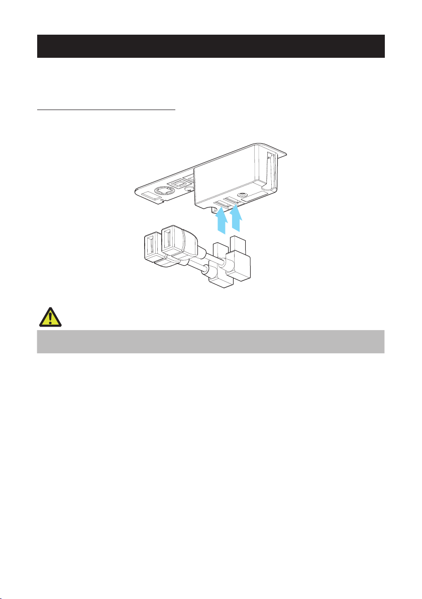
3.13 Mounting the Cable Cover
1
Align the claws of the cable cover with the grooves in the printer main unit and then
insert them.
1. Cable cover
——
50
Page 51

3.14 Precautions for Creating Applications and Practical Operations
If printing is done immediately after the paper is partially cut and torn off, the top of the
next print out may be distorted.
For printing after cutting, we recommend to print with the rst line empty.
If you are using a serial interface that has a slow data transmission speed, streaks may
appear in the printouts when you are printing graphics or gradated text, which require
large amounts of data.
USB interfaces may be susceptible to the effects of electromagnetic interference from
the host or environment.
If this is the case, try using a cable with ferrite cores on both ends, which are very effective at eliminating EMI.
3.15 Download Site for Various Electronic Files
You can view support information and download the latest documents, drivers, utilities,
etc. from the following site.
http://www.citizen-systems.co.jp/support/download/printer/ct-s751/
51
——
Page 52

4. MAINTENANCE AND
2
1
TROUBLESHOOTING
4.1 Periodic Cleaning
A dirty print head or platen may reduce printing quality or cause malfunctions. We recommend cleaning the printer periodically (every 2 to 3 months) as shown below.
1. Turn off the power.
2. Push down the cover open lever to open the paper cover.
3. Wait a few minutes until the print head cools.
4. Use a cotton swab dampened with ethyl alcohol to wipe off any dirt and dust that is on
the print head and platen.
1. Print head
2. Platen
CAUTION
When opening the paper cover, be careful not to touch the entrance of the blade of the auto
cutter.
The print head is very hot immediately after printing. Be careful not to touch it with your
hands.
Do not touch the print head with bare hands or metal objects.
Refer to PRECAUTIONS IN HANDLING THE PRINTER
——
52
Page 53

4.2 Clearing a Cutter Error
If the auto cutter stops during the auto cutter operation with the blade of the auto cutter
in the open position due to foreign matter entering, paper jamming, etc., the CUTTER
LED ashes. When a cutter error occurs, resolve the cutter error with the following
procedure.
1. Turn on the power.
2. Push down the cover open lever to open the paper cover.
3. Remove any jammed paper including any scraps of paper. (Remove the paper roll that
is loaded in the holder also.)
4. Reload the paper roll and close the paper cover.
CAUTION
When opening the paper cover, be careful not to touch the entrance of the blade of the auto
cutter.
The print head is very hot immediately after printing. Be careful not to touch it with your
hands.
Do not touch the print head with bare hands or metal objects.
Refer to PRECAUTIONS IN HANDLING THE PRINTER
53
——
Page 54

4.3 Self Test
You can use self test to check for printer problems.
Performing a self test operation
1. While paper is loaded, press and hold the FEED button and turn on the power.
2. Hold the FEED button down for about one second until the buzzer sounds. Release the
button to start self test. The printer will print its model name, version, memory switch
settings, and built-in fonts.
1. Printer type name
2. Firmware version
3. Interface settings
4. Buffer size
5. Memory switch settings
54
——
Page 55

4.4 Hexadecimal Dump Printing
Print received data in hexadecimal. If problems such as missing or duplicated data
occur, this function allows you to check whether or not the printer is receiving data correctly.
How to do hexadecimal dump printing
1. Load paper.
2. While the paper cover is open, hold down the FEED button as you turn on printing
power. Keep FEED button pressing until the POWER LED starts to ash, and then
close the paper cover.
3. The printer will print “HEX dump print mode” followed by the received data printed in
hexadecimal numbers and some characters.
How to stop hexadecimal dump printing
Do one of the following to stop printing.
Press the FEED button consecutively three times
Turn off the power
Receive a reset command from an interface
CAUTION
The printer prints “.” if there is no character corresponding to the data.
None of the commands function during hexadecimal dump printing.
If print data does not cover a complete line, press the FEED button to advance the paper.
Print example
HEX dump print mode
61 62 63 64 65 66 67 0A 0D 0D 0D 0D abcdefg.....
55
.....D0 D0 D0
——
Page 56

4.5 Error Indications
Paper end, paper near-end
The end of the roll of paper is detected at two stages, paper near-end and
paperend.
When paper near-end is detected, the PAPER LED ashes. Prepare a new paper
roll.
When paper end is detected, the PAPER LED lights and the buzzer sounds. Load a
new paper roll. Memory switch settings can be used to disable the buzzer.
Cover Open
If the cover is opened, the COVER LED lights and a buzzer sounds. The buzzer
may not sound depending on the memory switch setting. Do not open the cover
during printing. If the cover is accidentally opened, the COVER LEDashes.
Check the paper, pull it straight out of the printer by a couple of centimeters, and
then close the cover. Printing restarts. A command must be sent to restart printing
depending on the memory switch setting.
Cutter error
If the auto cutter cannot move because of a paper jam or something else, the
CUTTER LED ashes and the buzzer sounds. Remove the cause of the trouble and
press the FEED button. If the auto cutter still does not move and the paper cover
cannot be opened, refer to “Clearing a Cutter Error.”
Refer to 4.2 Clearing a Cutter Error
Print head hot
When you print dense characters, dark images, or for an extended time in a hot
environment, the print head temperature increases. If the print head exceeds a
specied temperature, the printer stops printing and waits for the print head to
cool. When this happens, the PAPER LED, CUTTER LED, and COVER LED ash.
Printing resumes automatically when the print head cools.
——
56
Page 57

The status display for various messages is shown below.
Status PAPER LED CUTTER LED COVER LED SERVICE LED Buzzer*1
Paper near-end
Paper-end Lit Unlit Unlit Unlit Yes*2
Cover open*3 Unlit Unlit Lit Unlit Yes*2
Cover open II*4 Unlit Unlit
Unlit Unlit Unlit No
Unlit Yes*2
Cutter locked Unlit
Low-voltage error
High-voltage error Unlit Unlit Unlit
System error Unlit Unlit Unlit
Memory error Unlit Unlit Unlit
Print head hot
Notes:
*1: Buzzer sounds when MSW5-1 (buzzer setting) is set to ON.
*2: MSW10-5 (buzzer event) can be congured to disable the buzzer.
*3: Indicated when a cover is opened during standby.
*4: Indicated when a cover is opened during standby.
Unlit Unlit Ye s
Unlit No
No
No
No
Unlit No
57
——
Page 58

4.6 Paper Jams
Take care to avoid obstruction of the paper outlet and paper jamming around the outlet
during printing.
If paper cannot get out of the printer, it can roll up on the platen inside the printer and
cause an error.
If the paper wraps around the platen, open the paper cover and carefully pull the paper
out.
4.7 Precautions for Performing Printing for Which Printing Speed Changes
When printing for which the printing speed changes is performed, white lines may be
printed or paper may not be fed depending on the printing conditions. To prevent these
problems, change the following memory switch settings.
1. Enable MSW2-3 (buffering).
2. Increase the baud rate of MSW7-1 (serial baud rate).
3. Change MSW10-2 (print speed) to a lower level.
CAUTION
Depending on the serial interface transmission speed, ambient temperature, print data duty, and
other factors, changing the above settings may not eliminate the problems.
58
——
Page 59

5. OTHER
108
5.1 External Views and Dimensions
125 165
(Unit: mm)
59
——
Page 60

5.2 Printing Paper
(Unit: mm)
Use the paper shown in the following table or paper of the same quality.
Paper type Product name
Recommended
thermal roll paper
Nippon Paper TP50KR-2Y, TP50KJ-R, TL69KS-LH
Oji Paper PD150R, PD160R, PD160R-63
Mitsubishi Paper Mills HP220AB-1, P220AB
Koehler KT48-FA
(Unit: mm)
Paper width 80
Max. printing width 72
4
Paper width 58
Printing width
48 (384 dot)
Paper thickness (μm) 53 to 85
Core inner diameter d (mm) ø12
Core outer diameter D (mm) ø18
+0
-1
+0
-1
CAUTION
Use thermal paper that is wound as follows:
Not creased and ts tight to the core.
Not folded.
Not glued to the core.
Rolled with the printable side out.
Printing surface
4
D
d
83 or less
55
65-85 µm
60
——
Page 61

5.3 Manual Setting of Memory Switches
Selectable item
Memory switches are used to set various printer settings. Memory switches can be set
manually, or by utilities or commands. This section explains how to perform manual
settings.
For information on how to set the memory switches using commands, please refer to
the Command Reference.
Quick setting mode
The settings for the memory switches for a replacement printer’s manufacturer, model,
paper width, and character spacing can be set at the same time to the optimum settings.
Do the settings while conrming the selected items on the printout.
1. Load paper.
2. While the paper cover is open, press and hold the FEED button and turn on the power.
3. Press the FEED button three and close the paper cover.
The printer enters memory switch quick setting mode.
The selectable item “Model” and the selection are printed.
Model ( CITIZEN CT-S310 )
Selection
4. Press the FEED button.
5. Press the FEED button for at least two seconds.
6. Repeat steps 4 and 5 to select and set the printer’s model, paper width, character
7. Press the FEED button for at least two seconds.
A selection is printed in order through the cycle each time the FEED button is pressed.
Press the FEED button until the selection you want is printed.
The selection is set.
If there is another selectable item, it and the selection are printed.
spacing (EPSON T88 only).
When all the items are set, “Save To Memory” is printed.
The changed memory switch settings are saved and a list of them is printed.
The printer exits quick setting mode when printing is nished.
——
61
Page 62

Selected item Automatic memory switch settings
Manufacturer
CITIZEN
CT-S310
EPSON
T88
EPSON
203dpi
Paper
width
58 mm - WaitData Invalid 384 dots 80 mm - WaitData Invalid 576 dots -
58 mm
80 mm
80 mm - WaitData Invalid 576 dots 0 dot
58 mm - WaitData Invalid 420 dots -
Character
space
0 dot WaitData Invalid 360 dots 0 dot
1 dot WaitData Invalid 390 dots 1 dot
0 dot WaitData Invalid 512 dots 0 dot
1 dot WaitData Invalid 546 dots 1 dot
MSW2-4
Full Col
Print
MSW3-7
CBM1000
Mode
MSW8-1
Print Width
MSW6-2
Character
Space
62
——
Page 63

Individual setting mode
Set the memory switches individually.
Do the settings while conrming the memory switch function and settings on the printout.
1. Load paper.
2. While the paper cover is open, press and hold the FEED button and turn on the power.
3. Press the FEED button twice and close the paper cover.
The printer enters the mode for setting memory switches individually.
The printer prints “Memory SW (1)” and the current setting, 0 (off) or 1 (on).
(The current settings for memory switches 7 to 13 are not printed.)
Current memory switch
4. Press the FEED button.
Each press of the FEED button cycles through the list of memory switches in the following
sequence: “Memory SW (1)” > “Memory SW (2)” > ...“Memory SW (11)” or “Memory SW (13)”
> “Save To Memory” > “Memory SW (1)”.
Press the FEED button until the number for the memory switch you want to change is printed.
5. Press the FEED button for at least two seconds.
A setting for the memory switch is printed, through the cycle, each time the FEED button is
pressed for at least two seconds.
Press the FEED button for at least two seconds to cycle through the list until the function of
the memory switch you want to change is printed.
Memory switch function
6. Press the FEED button.
A setting is printed each time the FEED button is pressed in order through the cycle.
When the current settings are printed, the COVER LED lights.
Press the FEED button until the setting you want is printed.
7. Press the FEED button for at least two seconds.
The selected settings are set.
The next memory switch function and settings are printed.
Current setting
Current setting
63
——
Page 64

8. Repeat steps 5 to 7 to change different functions for the current memory switch num-
ber.
9. Open the paper cover and close it.
The changed memory switch settings are printed.
10. Repeat steps 4 to 9 to change functions for a different memory switch number.
11. Press the FEED button until “Save To Memory” is printed.
12. Press the FEED button for at least two seconds.
The changed memory switch settings are saved and a list of them is printed.
The printer exits individual setting mode when printing is nished.
Memory switch initialization
Set all the memory switches to the factory settings.
1. Do steps 1 through 3 of the procedure to enter individual setting mode.
2. Press the FEED button until “Save To Memory” is printed.
3. Open the paper cover.
4. Press the FEED button for at least two seconds.
All memory switches change to the factory settings.
5. Close the paper cover.
64
——
Page 65

The function of each memory switch is shown in the following table. (Shaded values
are factory settings.)
Switch no. Function OFF ON
MSW1-1 Power ON Info Valid Not Send
MSW1-2 Buffer Size 4K bytes 45 bytes
MSW1-3 Busy Condition Full/Err Full
MSW1-4 Receive Error Print“?” No Print
MSW1-5 CR Mode Ignored LF
MSW1-6 Reserved Fixed —
MSW1-7 DSR Signal Invalid Valid
MSW1-8 INIT Signal Invalid Valid
MSW2-1 Reserved — Fixed
MSW2-2 Auto Cutter Invalid Valid
MSW2-3 Spool Print Invalid Valid
MSW2-4 Full Col Print LineFeed WaitData
MSW2-5 Resume aft PE Next Top
MSW2-6 Reserved Fixed —
MSW2-7 Reserved Fixed —
MSW2-8 PNE Sensor Valid Invalid
MSW3-1 Resume Cttr Err Valid Invalid
MSW3-2 PE signal by PNE Valid Invalid
MSW3-3 Reserved Fixed —
MSW3-4 Reserved Fixed —
MSW3-5 Reserved Fixed —
MSW3-6 Reserved Fixed —
MSW3-7 CBM1000 Mode Invalid Valid
MSW3-8 Resume Open Err Close Command
MSW4-1 Reserved Fixed —
MSW4-2 Reserved Fixed —
MSW4-3 Feed&Cut at TOF Invalid Valid
MSW4-4 Reserved Fixed —
MSW4-5 Reserved Fixed —
MSW4-6 Reserved Fixed —
MSW4-7 Reserved Fixed —
MSW4-8 Partial Only Invalid Valid
——
65
Page 66

Switch no. Function OFF ON
MSW5-1 Buzzer Valid Invalid
MSW5-2 Line Pitch 1/360 1/406
MSW5-3 USB Mode Virtual COM Printer Class
MSW5-4 Reserved Fixed —
MSW5-5 Reserved Fixed —
MSW5-6 Reserved Fixed —
MSW5-7 Reserved Fixed —
MSW5-8 Reserved Fixed —
MSW6-1 Act. For Driver Invalid Valid
MSW6-2 Character Space Invalid Valid
MSW6-3 USB Power Save Invalid Valid
MSW6-4 Reserved Fixed —
MSW6-5 Reserved Fixed —
MSW6-6 Reserved Fixed —
MSW6-7 USB Power@PW-OFF Invalid Valid
MSW6-8 Power ON trigger Power switch ON AC power input
Switch no. Function Initial setting Setting value
MSW7-1 Baud Rate 9600 bps 1200 bps, 2400 bps, 4800 bps, 9600 bps, 19200 bps,
MSW7-2 Data Length 8bits 7bits, 8bits
MSW7-3 Stop Bit 1bit 1bit, 2bits
MSW7-4 Parity NONE NONE, ODD, EVEN
MSW7-5 Flow Control DTR/DSR DTR/DSR, XON/XOFF
MSW7-6 DMA Control Valid Valid, Invalid
MSW7-7 VCom Protocol PC Setting PC Setting, DTR/DSR, XON/XOFF
38400 bps, 57600 bps, 115200 bps
MSW8-1 Print Width 576 dots 576 dots, 546 dots, 512 dots, 420 dots, 390 dots, 384
MSW8-3 Top Margin 11mm 2mm, 3mm, 4mm, 5mm, 6mm, 7mm, 8mm, 9mm,
MSW8-4 Line Gap Reduce Invalid Invalid, 3/4, 2/3, 1/2, 1/3, 1/4, 1/5, ALL
MSW8-5 Reduced Char V/H 100% / 100% 100% / 100%, 75% / 100%, 50% / 100%, 100% / 75%,
MSW8-6 Auto Side Shift Invalid Invalid, 1 dot, 2 dots, 3 dots, 4 dots, 5 dots, 6 dots, 7
dots, 360 dots
10mm, 11mm
75% / 75%, 50% / 75%
dots
——
66
Page 67

Switch no. Function Initial setting Setting value
MSW9-1 Code Page PC437 PC 437, Katakana, PC 850, PC 858, PC 860, PC 863,
MSW9-2 Int’Char Set U.S.A USA, France, Germany, England, Denmark, Sweden,
MSW9-4 Kanji code Invalid Disabled, JIS (Japan), SJIS: CP932 (Japan), SJIS:
PC 865, PC 852, PC 866, PC 857, WPC1252, Space
page, PC 864, ThaiCode11 1Pass, ThaiCode11
3Pass, ThaiCode18 1Pass, ThaiCode18 3Pass,
TCVN-3, WPC1258
Italy, Spain, Japan, Norway, Denmark 2, Spain 2, Latin
America, Korea, Croatia, China, Vietnam
X0213 (Japan), GB18030 (China), KS Hangul (South
Korea), EUC Hangul (South Korea), BIG5-HKSCS
MSW10-1 Print Density 100 % 70 %, 75 %, 80 %, 85 %, 90 %, 95 %, 100 %, 105 %,
MSW10-2 Print Speed Level 9 Level 1, Level 2, Level 3, Level 4, Level 5, Level 6,
MSW10-4 Old Command Invalid Invalid, CBM1, CBM2
MSW10-5 Buzzer Event Not By C.
Open
MSW10-6 Buzzer Sound Tone 2 Tone 1, Tone 2, Tone 3, Tone 4
MSW13-1 Security/Target Low/All Low/All, Mid/All, Mid/Paired only, Hi/All, Hi/Paired only
MSW13-5 BT Device Scan Discoverable No Response, Discoverable
MSW13-6 Auto Reconnect Valid Valid | Invalid, Valid
110 %, 115 %, 120 %, 125 %, 130 %, 135 %, 140 %
Level 7, Level 8, Level 9
All Event/Error, Not by C.Open, Not by C.Open/PE
67
——
Page 68

FRANÇAIS
68
——
Page 69

PRÉCAUTIONS GÉNÉRALES
Veillez à lire le présent mode d’emploi avant d’utiliser ce produit. Après l’avoir lu,
conservez-le dans un endroit sûr et facilement accessible pour toute référence
ultérieure.
Les informations contenues dans le présent mode d’emploi sont sujettes à mo-
dication sans préavis.
La reproduction ou le transfert d’une partie ou de la totalité de ce document, par
quelque moyen que ce soit, sans l’autorisation de Citizen Systems, est interdit.
Notez que Citizen Systems ne peut être tenu responsable des conséquences du
fonctionnement, quelles que soient les omissions, erreurs ou fautes d’impression présentes dans ce mode d’emploi.
Citizen Systems n’est en aucun cas responsable de tout problème causé par
l’utilisation d’options ou de produits consommables qui ne sont pas indiqués
dans ce mode d’emploi.
Sauf en cas de spécication contraire dans ce mode d’emploi, n’essayez pas
d’entretenir, de démonter ou de réparer ce produit.
Citizen Systems n’est en aucun cas responsable de tout dommage attribuable
à une opération/manipulation incorrecte ou à un environnement d’exploitation
inapproprié qui ne sont pas indiqués dans ce mode d’emploi.
Les données sont prévues fondamentalement pour un usage provisoire et ne
sont pas stockées pendant une longue période ou de manière permanente.
Notez que Citizen Systems ne peut être tenu responsable des dommages ou
pertes de prots résultant de pertes de données occasionnées par des accidents, des réparations, des tests ou autres.
Si vous trouvez des omissions ou des erreurs ou si vous avez des questions,
veuillez contacter votre revendeur Citizen Systems.
S’il manque des pages ou si des pages sont inversées, contactez votre reven-
deur Citizen Systems pour remplacer le mode d’emploi.
Les accessoires électroniques portant la mention « Made for iPod », « Made for
iPhone » et « Made for iPad » ont été conçus pour fonctionner respectivement avec un
iPod, un iPhone ou un iPad et sont certiés conformes aux exigences d’Apple par le
fabricant. Apple n’est pas responsable pour le fonctionnement de cet appareil ou de sa
compatibilité avec les normes réglementaires et de sécurité.
Veuillez noter que l’emploi de cet accessoire avec un iPod, iPhone ou iPad peut affec-
ter les performances sans l.
——
69
Page 70

iPad, iPhone et iPod touch sont des marques commerciales d’Apple Inc., déposées
aux États-Unis et dans d’autres pays. iPad Air et iPad mini sont des marques commerciales d’Apple Inc.
EPSON et ESC/POS sont des marques déposées de Seiko Epson Corporation.
QR Code est une marque déposée de DENSO WAVE INCORPORATED.
Ethernet est une marque déposée de Fuji Xerox Corporation.
®
Bluetooth
est une marque commerciale déposée de Bluetooth-SIG Inc.
CITIZEN est une marque enregistrée de Citizen Watch Co. Ltd.
Toutes les autres marques de commerce appartiennent à leurs propriétaires res-
pectifs.
Citizen Systems utilise ces marques de commerce conformément à la licence des
propriétaires respectifs.
Copyright© CITIZEN SYSTEMS JAPAN CO., LTD. 2019
70
——
Page 71

PRÉCAUTIONS DE SÉCURITÉ... À RESPECTER RIGOUREUSEMENT
Veuillez lire attentivement ces PRÉCAUTIONS DE SÉCURITÉ avant d’utiliser l’appareil pour la première fois. Une manipulation incorrecte peut entraîner des accidents
(tels qu’un incendie, un choc électrique ou des blessures).
An d’éviter tout risque de blessures aux opérateurs ou à des tiers ou de dommages
matériels, des symboles d’avertissement spéciaux sont utilisés dans le Mode d’emploi
pour indiquer les points importants à respecter rigoureusement.
Après avoir lu ce mode d’emploi, conservez-le dans un endroit sûr et facilement
accessible pour toute référence ultérieure.
Certaines des descriptions contenues dans ce mode d’emploi peuvent ne pas
s’appliquer à certains modèles d’imprimantes.
Ce qui suit indique le degré de danger et de dommage encouru si l’imprimante n’est
pas utilisée correctement, sans tenir compte des instructions indiquées par les symboles d’avertissement. Veillez à lire attentivement ces informations.
AVERTISSEMENT
Le non-respect des précautions indiquées par ce symbole peut provoquer des blessures
mortelles ou graves.
ATTENTION
Le non-respect des précautions indiquées par ce symbole peut provoquer des blessures ou
des dommages matériels.
Ce symbole sert à attirer votre attention sur des points importants.
Ce symbole sert à vous avertir d’un risque de choc électrique ou de dommage électrostatique.
Ce symbole indique la nécessité de débrancher l’imprimante de la prise murale.
Ce symbole indique que l’alimentation électrique doit être mise à la terre.
Ce symbole est utilisé pour indiquer des informations utiles, telles que des procédures, des instructions ou d’autres informations similaires.
Ce symbole sert à indiquer des actions interdites.
——
71
Page 72

PRÉCAUTIONS RELATIVES À L’INSTALLA-
TION DE L’IMPRIMANTE
AVERTISSEMENT
N’utilisez pas et ne rangez pas cet appareil dans un endroit où il sera exposé
à :
* des ammes ou de l’air humide.
* la lumière directe du soleil.
* de l’air chaud ou des radiations d’un appareil de chauffage.
* de l’air salin ou des gaz corrosifs.
* une atmosphère mal ventilée.
* des réactions chimiques en laboratoire.
* de l’huile, des particules d’acier ou de la poussière dans l’air.
* de l’électricité statique ou des champs magnétiques puissants.
De tels endroits présentent un risque de dommages à l’imprimante, ainsi
que de panne de l’appareil, de surchauffe, d’émission de fumée, d’incendie
ou de choc électrique.
De plus, il faut toujours éviter ces endroits car ils peuvent entraîner un
incendie ou des chocs électriques.
Ne laissez pas tomber de corps étrangers et ne renversez pas de liquide
dans l’imprimante. Ne placez aucun objet sur l’imprimante.
Ne faites pas tomber d’objets métalliques, tels que des trombones, des
épingles ou des vis, dans l’imprimante.
Ne placez pas de vase, de pot de eurs ou d’objets contenant de l’eau sur
l’imprimante.
Ne renversez pas de café, de boissons gazeuses ou tout autre liquide dans
l’imprimante.
Ne vaporisez pas d’insecticide ou tout autre produit chimique liquide sur
l’imprimante.
Si un objet métallique tombe accidentellement dans l’imprimante, il existe
un risque de panne de l’imprimante, d’incendie ou de choc électrique.
Dans ce cas, mettez immédiatement l’imprimante hors tension, débranchez-la de la prise d’alimentation et contactez votre revendeur local Citizen
Systems.
Ne manipulez pas l’imprimante de la manière suivante :
Ne soumettez pas l’imprimante à de forts impacts ou à des secousses violentes
(ne marchez pas sur l’imprimante, ne la faites pas tomber, ne la heurtez pas,
etc.).
Ne tentez pas de démonter ou de modier l’imprimante.
De telles actions présentent un risque de dommages à l’imprimante, ainsi
que de panne de l’appareil, de surchauffe, d’émission de fumée, d’incendie
ou de choc électrique.
De plus, il faut toujours éviter de réaliser ces actions car elles peuvent
entraîner un incendie ou des chocs électriques.
72
——
Page 73

Cet appareil ne convient pas à une utilisation dans des endroits où des
enfants sont susceptibles d’être présents. Installez, rangez et utilisez l’appareil hors de la portée des enfants.
Les appareils électriques risquent de provoquer des blessures ou des acci-
dents inattendus s’ils sont manipulés ou utilisés de manière incorrecte.
Laissez le cordon d’alimentation et les câbles de signaux hors de la por-
tée des enfants. En outre, les enfants ne doivent pas pouvoir accéder aux
pièces internes de l’imprimante.
Le sac en plastique dans lequel l’imprimante est emballée doit être mis au
rebut correctement et conservé hors de la portée des enfants. Une suffocation peut se produire si le sac est mis sur la tête.
ATTENTION
N’utilisez pas l’imprimante dans les conditions suivantes.
Évitez les emplacements soumis à des vibrations ou à une certaine instabilité.
Évitez les emplacements où l’imprimante n’est pas de niveau.
L’imprimante pourrait tomber et entraîner des blessures.
La qualité de l’impression peut se détériorer.
N’obstruez pas les orices d’aération de l’imprimante.
Ne placez rien sur l’imprimante.
Ne couvrez pas et n’enroulez pas l’imprimante dans des vêtements ou des cou-
vertures.
De la chaleur pourrait s’accumuler et déformer le boîtier ou déclencher un
incendie.
Évitez d’utiliser l’imprimante à proximité d’une radio ou d’un téléviseur ou de
l’alimenter à partir de la même prise électrique que ces appareils.
Éviter d’utiliser l’imprimante connectée ensemble avec un câble ou un cordon qui
ne présente aucune protection contre les parasites.
(Pour les interconnexions, utilisez des câbles blindés ou torsadés et des noyaux
en ferrite, ou d’autres dispositifs anti-bruit.)
Évitez d’utiliser l’imprimante avec un appareil produisant une source de bruit
importante.
L’imprimante peut avoir un effet négatif sur les transmissions radio ou
télévisées. Dans certains cas également, les appareils électriques proches
peuvent avoir un effet négatif sur l’imprimante et causer des erreurs de
données ou des pannes.
Installée dans un sens autre que ceux indiqués.
Un dysfonctionnement, une panne ou un choc électrique peut se produire.
73
——
Page 74

Reliez l’imprimante à la terre.
Les fuites électriques peuvent entraîner des décharges électriques.
Ne connectez pas la terre de l’imprimante aux éléments suivants :
Une explosion de gaz peut se produire.
* Tuyaux de gaz
* Terre d’une ligne téléphonique
* Paratonnerre
En cas de foudre, une surtension de courant importante peut provoquer un
incendie ou un choc électrique.
* Conduites d’eau
Les conduites d’eau en plastique ne doivent pas être utilisées pour la mise à la
terre. (Celles approuvées par le Département des Eaux peuvent être utilisées.)
Avant de connecter le l de terre à l’imprimante ou de le déconnecter de
l’imprimante, débranchez-le toujours de la prise électrique.
74
——
Page 75

PRÉCAUTIONS DE MANIPULATION DE L’IMPRIMANTE
AVERTISSEMENT
Observez les précautions suivantes pour l’alimentation électrique et le cordon d’alimentation :
Ne branchez pas et ne débranchez pas le cordon d’alimentation avec les mains
mouillées.
Utilisez l’imprimante uniquement avec la tension d’alimentation et la fréquence
spéciées.
Utilisez uniquement l’adaptateur secteur spécié avec l’imprimante.
Utilisez uniquement le cordon d’alimentation fourni avec l’imprimante et n’utilisez
jamais le cordon d’alimentation fourni avec un autre appareil.
Vériez si la prise sur laquelle l’imprimante est alimentée a une capacité suf-
sante.
N’alimentez pas l’imprimante à partir d’un bloc multiprise ou d’une che multi-
prise servant déjà à d’autres appareils.
Ne branchez pas le cordon d’alimentation dans une prise électrique comportant
de la poussière ou des débris.
N’utilisez pas un cordon d’alimentation déformé ou endommagé.
Ne déplacez pas l’imprimante lorsqu’elle est sous tension.
Toute manipulation incorrecte peut entraîner une panne de l’imprimante,
une émission de fumée, un incendie ou un choc électrique.
Le cordon d’alimentation risque de surchauffer ou de prendre feu, ou le
disjoncteur risque de se déclencher en raison d’une surchauffe.
Ne posez aucun objet sur le cordon d’alimentation. Ne placez pas l’imprimante à
un emplacement où le cordon d’alimentation risque d’être piétiné.
Ne pliez pas, ne tordez pas et ne tirez pas excessivement sur le cordon d’ali-
mentation. Ne transportez pas non plus le produit dans de telles conditions.
Ne tentez pas de modier inutilement le cordon d’alimentation.
Ne placez pas le cordon d’alimentation à proximité d’un appareil de chauffage.
Le non-respect de ces avertissements peut provoquer la rupture des ls ou
de l’isolation, ce qui peut entraîner une fuite électrique, un choc électrique
ou une panne de l’imprimante.
En cas d’endommagement du cordon d’alimentation, veuillez contacter
votre revendeur Citizen Systems.
Ne laissez rien autour de la prise électrique.
Alimentez l’imprimante à partir d’une prise électrique pratique et facile d’accès
en cas d’urgence.
Retirez la che de manière à arrêter immédiatement l’imprimante en cas
d’urgence.
Introduisez à fond la che d’alimentation dans la prise.
Si vous ne comptez pas utiliser l’imprimante pendant une période prolongée,
débranchez-la de la prise électrique.
Tenez la che et la prise quand vous effectuez le branchement ou le débranche-
ment du cordon d’alimentation ou du câble de signal après avoir éteint l’imprimante et l’appareil qui lui est connecté.
75
——
Page 76

ATTENTION
L’étiquette d’avertissement est apposée à l’emplacement indiqué sur l’illustration suivante. Lisez attentivement les précautions de manipulation avant d’utiliser l’imprimante.
Ces étiquettes indiquent le risque de
brûlures en cas de contact avec la tête
qui devient chaude et le risque de
coupures au niveau des mains en cas
de contact avec le système de découpe
automatique lors de l’ouverture du
capot papier.
Ne transportez pas cette imprimante avec un rouleau de papier à l’intérieur.
Une panne de l’imprimante ou des dommages peuvent survenir.
Pour éviter tout risque de dysfonctionnement ou de panne, respectez les
instructions suivantes :
N’ouvrez pas le capot papier pendant l’impression.
Évitez de faire fonctionner l’imprimante sans rouleau de papier correctement
chargé.
Évitez d’utiliser du papier non conforme aux spécications.
Cela risque d’entraîner une qualité d’impression médiocre.
Évitez d’utiliser des morceaux de papier déchirés ou du papier collé avec du
ruban adhésif en plastique.
Évitez de tirer à la main avec force sur du papier déjà chargé.
Évitez d’utiliser un objet pointu pour appuyer sur les touches du panneau.
Veillez à insérer fermement les ches de câble dans leur douille de
connexion.
Une connexion croisée risque d’endommager les composants électro-
niques internes de l’imprimante ou le matériel du système hôte.
Utilisez l’imprimante uniquement avec des dispositifs ayant les spécications indiquées pour le solénoïde du connecteur de l’ouverture du tiroir-caisse.
Le non-respect de cette précaution risque de provoquer un dysfonctionne-
ment ou une panne.
——
76
Page 77

Pour éviter tout risque de blessures et l’aggravation des dommages à l’imprimante, respectez les instructions suivantes :
Ne touchez pas à la surface d’impression de la tête thermique.
Ne touchez pas les pièces mobiles (système de découpe du papier, engrenages,
pièces électriques actives, par exemple) lors du fonctionnement de l’imprimante.
En cas d’anomalie, ne tentez pas de réparer l’imprimante. Conez-la au service
de Citizen Systems pour la réparation.
Veillez à ne pas vous coincer les mains ou les doigts dans les capots.
Faites attention aux bords tranchants de l’imprimante. Ils risquent de vous bles-
ser ou de provoquer des dommages matériels.
Cela pourrait entraîner un choc électrique, des brûlures ou des blessures.
Si l’imprimante émet de la fumée, une odeur étrange ou un
bruit anormal lors de l’impression, quittez immédiatement la
session d’impression en cours et débranchez l’imprimante de la
prise électrique.
ENTRETIEN JOURNALIER
Observez les précautions suivantes pour l’entretien quotidien.
Lors du nettoyage de l’imprimante, mettez-la toujours hors tension et débran-
chez-la de la prise électrique.
Utilisez un chiffon doux et sec pour nettoyer la surface du boîtier de l’imprimante.
Pour les taches tenaces, utilisez un chiffon doux légèrement imbibé d’eau.
N’utilisez jamais de solvants de nettoyage organiques, tels que de l’alcool, du
diluant, du trichloréthylène, du benzène ou de la cétone. N’utilisez jamais de
chiffon de nettoyage imprégné d’un produit chimique.
Pour enlever la poussière de papier, utilisez une brosse souple.
ATTENTION
La tête thermique conserve une température dangereusement élevée immédiatement après l’impression.
Laissez-la refroidir avant de démarrer les travaux d’entretien.
——
77
Page 78

TABLE DES MATIÈRES
1. PRÉSENTATION GÉNÉRALE .......................................................79
1.1 Fonctionnalités ..................................................................................79
1.2 Déballage ..........................................................................................80
1.3 Classication des modèles ................................................................ 81
1.4 Spécications de base ......................................................................81
2. EXPLICATION DES COMPOSANTS DE L’IMPRIMANTE ............84
2.1 Apparence extérieure de l’imprimante ...............................................84
2.2 À l’intérieur du capot papier ...............................................................86
2.3 Autres fonctions intégrées ................................................................. 87
3. INSTALLATION .............................................................................. 89
3.1 Branchement du cordon d’alimentation secteur ................................ 89
3.2 Carte d’interface série ....................................................................... 90
3.3 Interface USB ....................................................................................91
3.4 Carte d’interface Bluetooth ................................................................ 92
3.5 Carte d’interface de l’hôte USB Bluetooth ......................................... 95
3.6 Ethernet (LAN)/Carte d’interface LAN sans l ................................. 101
3.7 Port d’alimentation électrique USB ..................................................107
3.8 Branchement du tiroir-caisse ........................................................... 109
3.9 Précautions d’installation de l’imprimante ....................................... 111
3.10 Réglage du capteur de n de papier proche .................................112
3.11 Chargement du papier ...................................................................113
3.12 Séparateur pour rouleau de papier de 58 mm de large ................115
3.13 Montage du cache du câble ..........................................................116
3.14 Précautions pour la création d’applications et les
opérations pratiques ...................................................................... 117
3.15 Site de téléchargement de divers chiers électroniques ...............117
4. ENTRETIEN ET DÉPANNAGE ....................................................118
4.1 Nettoyage périodique ......................................................................118
4.2 Correction d’une erreur de découpe ................................................119
4.3 Auto-test ..........................................................................................120
4.4 Impression d’un vidage hexadécimal ..............................................121
4.5 Indications d’erreur .......................................................................... 122
4.6 Bourrages papier ............................................................................. 124
4.7 Précautions relatives à l’impression avec des changements de
vitesse d’impression ........................................................................ 124
5. DIVERS ........................................................................................125
5.1 Vues et dimensions externes ...........................................................125
5.2 Papier d’impression ......................................................................... 126
5.3 Réglage manuel des commutateurs de mémoire ............................ 127
——
78
Page 79

1. PRÉSENTATION GÉNÉRALE
L’imprimante thermique par ligne de la série CT-S751 est conçue pour une utilisation
avec une grande variété d’équipements, y compris des terminaux de données, des
terminaux de points de vente et des imprimantes cuisine.
Ces imprimantes possèdent de nombreuses fonctionnalités an de pouvoir être utilisées pour une large gamme d’applications.
1.1 Fonctionnalités
Impression à grande vitesse jusqu’à 350 mm/s possible
Design élégant
Format compact d’une hauteur minimale
La structure d’éjection du papier avant permet une utilisation dans des endroits où
la hauteur est limitée.
Conforme à la norme d’étanchéité IPX1*
Largeurs de papier de 80 mm et 58 mm prises en charge
Équipée d’un système de découpe haute vitesse
Interface USB incluse de série
Avec un port d’alimentation électrique USB de série
Carte d’interface interchangeable
Fonction d’impression Web/XML incluse (modèle LAN câblé ou LAN sans l)
Fonction d’hôte USB pouvant contrôler les appareils périphériques incluse (modèle
d’hôte LAN câblé ou USB Bluetooth)
État de l’imprimante et erreurs indiquées par cinq DEL
Interface du tiroir-caisse intégrée
Fonction de mise hors tension par connexion USB disponible
Échelle de gris de 16 niveaux et impression claire
Fonction d’économie de papier disponible
Prise en charge des troisième et quatrième niveaux des jeux de caractères kanji de
JIS X0213
Prise en charge des jeux de caractères chinois simpliés et traditionnels et du jeu
de caractères hangul
Prise en charge d’UTF-8 à l’aide de commandes
Diverses personnalisations possibles à l’aide des commutateurs de mémoire
Enregistrement des caractères et logos dénis par l’utilisateur dans la mémoire de
l’utilisateur possible
Prise en charge des codes à barres, y compris les codes à barres 2D
Appui à la communication Apple MFi certié Bluetooth (modèle Bluetooth)
* : Le produit a été contrôlé an de déterminer que les gouttes d’eau tombant verticalement n’ont aucun effet
négatif, mais le produit n’est pas garanti comme étant complètement étanche.
79
——
Page 80

1.2 Déballage
Assurez-vous que les éléments suivants sont fournis avec l’imprimante.
NOM
Imprimante 1
Adaptateur secteur (37AD5) 1
Cordon d’alimentation secteur 1
Séparateur 1
Serre-câble *1 1
Câble USB en forme de L *2 1
QUANTI-
TÉ
ILLUSTRATION
Couvercle de câbles 1
Rouleau de papier échantillon 1 rouleau
Guide de démarrage rapide 2
*1 : Fourni avec le modèle RS
*2 : Inclus avec les modèle HBT
80
——
Page 81

1.3 Classication des modèles
34
Les numéros de modèle indiquent les fonctionnalités des imprimantes en fonction du
système suivant.
CT - S751 RS E- BK
12
1. Nom du modèle
2. Interface
RS: Série RS-232C+USB
ET: Ethernet+USB
HET: Ethernet (fonction d’hôte USB) + USB
BT: Bluetooth+USB
HBT: Bluetooth (fonction d’hôte USB)
WF: LAN sans l+Ethernet+USB
NN: USB
3. Marché
U : Amérique du Nord
E : Europe
I : Inde
4. Couleur du boîtier
WH : Blanc pur
BK : Noir
Contactez-nous au préalable pour des combinaisons spéciales, car certaines peuvent
ne pas être disponibles.
1.4 Spécications de base
Rubrique Spécications
Modèle CT-S751
Méthode d’impres-
sion
Largeurs d’impres-
sion
Densité de points 8 × 8 points/mm (203 ppp)
Vitesse d’impression 350 mm/s (vitesse maximale, niveau de densité d’impression de 100 %, 2800 lignes de
Méthode d’impression matricielle thermique par ligne
72 mm/576 points, 68,25 mm/546 points, 64 mm/512 points, 52,5 mm/420 points, 48,75
mm/390 points, 48 mm/384 points, 45 mm/360 points, valeur par défaut de 72 mm
points/s)
——
81
Page 82

Rubrique Spécications
Nombre de colonnes
d’impression *1
Taille des caractères *2
Type de caractère Caractères alphanumériques, caractères internationaux, PC437/850/852/857/858/
Mémoire utilisateur 384 Ko (capable de stocker les caractères et les logos dénis par l’utilisateur)
Types de code à
barres
Interligne 4,25 mm (1/6 pouce) (variable par commande)
Rouleau de papier Papier rouleau : 80 mm x maximum ø83 mm
Interface Série (RS-232C standard), USB, Bluetooth+USB, LAN, LAN sans l+LAN, LAN (fonc-
Ethernet 100BASE-TX/10BASE-T
LAN sans l IEEE802.11n, IEEE802.11a, IEEE802.11g, IEEE802.11b
Bluetooth Version : Bluetooth 3.0 + EDR
Port d’alimentation
électrique USB
Arrêt du tiroir-caisse Prend en charge 2 tiroirs-caisses
Tampon d’entrée 4 K octets/45 octets
Tension d’alimen-
tation
Consommation Environ 50 W (moyenne), 2 W ou moins (en veille), 0,2 W ou moins (état de mise hors
Adaptateur secteur
(37AD5)
Poids Environ 1,3 kg
Dimensions ex-
ternes
Température et
humidité de fonctionnement
Température et humidité de stockage
Fiabilité Durée de vie de la tête d’impression : 200 km, 200 millions d’impulsions (tempéra-
Normes de sécurité *3
Police Nombre maximum
de caractères
(colonnes) / 80 mm
Police A 48 35 12 × 24
Police B 64 46 9 × 24
Police C 72 52 8 × 16
Police A : 1,50 × 3,00 mm, Police B : 1,13 × 3,00 mm, Police C : 1,00 × 2,00 mm
860/863/864/865/866, WPC1252, WPC1258, katakana, ThaiCode 11/18 (1Pass/3Pass),
TCVN-3, kanji (premier, deuxième, troisième et quatrième niveaux JIS), kana,
caractères étendus, JIS X0213, GB18030, BIG5, KS Hangul, EUC Hangul
UPC-A/E, JAN(EAN) 13 chiffres/8 chiffres, ITF, CODE39, CODE128, CODABAR(NW-7), CODE93, PDF417, QR Code, GS1-DataBar
Épaisseur du papier : 53 à 85 μm (diamètre intérieur du rouleau de papier de 12 mm /
diamètre extérieur de 18 mm)
tion d’hôte USB) (port USB 2)), Bluetooth (fonction d’hôte USB) (port USB 2))
Prol : SPP (Serial Port Protocol, Prol de port série), iAP (iPod Accessory Protocol,
Protocole d’accessoires iPod)
Classe de puissance : Classe 2
2,1 A maximum
24 V CC ±5 %
tension par connexion USB)
Entrée nominale : 100 à 240 V CA, 50/60 Hz, 150 VA
Sortie nominale : 24 V CC, 2,1 A
125 (L) × 165 (P) × 108 (H) mm
De 5 à 45 °C, 10 à 90 % d’humidité relative (sans condensation)
De -20 à 60°C, 10 à 90 % d’humidité relative (sans condensation)
ture ambiante, humidité ambiante, papier recommandé spécié, épaisseur de papier
spéciée), Durée de vie du système de découpe automatique : 2 million de découpes (3
pouces), 1.5 million de découpes (2 pouces) (température ambiante, humidité am-
biante, papier recommandé spécié, épaisseur de papier spéciée)
UL, C-UL, FCC Classe A, marquage CE
Nombre maximum
de caractères
(colonnes) / 58 mm
Conguration des points
(points)
82
——
Page 83

Remarques :
*1 : Le nombre de colonnes imprimables est sélectionné avec le commutateur de
mémoire.
Le nombre de colonnes noté dans ce tableau se rapporte à des modèles typiques.
Le nombre de colonnes varie en fonction des spécications.
*2 : Les caractères apparaissent plus petits parce que les dimensions comprennent
une zone blanche autour de chaque caractère.
*3 : Cette norme s’applique lors de l’utilisation de notre adaptateur secteur (37AD5).
83
——
Page 84

2. EXPLICATION DES COMPOSANTS
1
5
6
DE L’IMPRIMANTE
2.1 Apparence extérieure de l’imprimante
Nom des composants
3
2
4
1. Capot papier
Ouvrez pour charger le papier.
Ouvrez également pour corriger une erreur de découpe.
* Le capot papier ne peut pas être utilisé pour la découpe manuelle.
Reportez-vous à 4.2 Correction d’une erreur de découpe
2. Levier d’ouverture du capot
Utilisez ce levier pour ouvrir le capot papier.
3. Touche POWER
Appuyez sur cette touche pendant deux ou trois secondes pour mettre l’appareil
sous ou hors tension.
4. Touche FEED
Appuyez sur cette touche pour faire avancer le papier.
En cas d’erreur de découpe, appuyez sur la touche FEED avec le capot papier
fermé après avoir supprimé la cause.
L’imprimante entre en mode de réglage des commutateurs de mémoire et
d’exécution d’un auto-test.
Reportez-vous à 4.3 Auto-test
5. Panneau de commande
6. Connecteurs arrière
Reportez-vous à 5.3 Réglage manuel des commutateurs de mémoire
——
84
Page 85

Panneau de commande
352 41
RS: Série RS-232C + USB
Le panneau de commande comporte cinq DEL et deux touches.
Nom de
voyant
POWER LED Ve r t
PAPER LED Ver t
CUTTER LED Ver t
COVER LED Ver t
SERVICE LED Orange
Couleur Description
S’allume lorsque l’appareil est sous tension, s’éteint lorsque
l’appareil est hors tension.
S’allume ou clignote lorsque la détection est faite qu’il n’y a
plus de papier ou très peu.
Peut également s’allumer ou clignoter lorsque d’autres
anomalies sont détectées.
Clignote lorsqu’une erreur de découpe est détectée.
Peut également s’allumer ou clignoter lorsque d’autres
anomalies sont détectées.
S’allume ou clignote lorsque un capot papier ouvert est
détecté.
Peut également s’allumer ou clignoter lorsque d’autres
anomalies sont détectées.
Clignote lorsqu’une anomalie de l’imprimante irrémédiable est
détectée.
Reportez-vous à 4.5 Indications d’erreur
Connecteurs arrière (exemple de l’interface série)
1. Connecteur d’interface (série, USB, etc.)
Connectez le câble d’interface.
2. Connecteur d’arrêt du tiroir-caisse
Connectez le câble du tiroir-caisse.
3. Connecteur d’alimentation
Connectez le câble de l’adaptateur secteur.
4. Connecteur USB
5. Port d’alimentation électrique USB
Alimentez un périphérique USB.
85
——
Page 86

2.2 À l’intérieur du capot papier
1
6
2, 3
5
1. Tête d’impression (thermique)
Imprime les caractères et les données graphiques sur le papier (rouleaux de
papier).
2. Capteur de n de papier proche (PNE)
Détecte quand le papier est proche de la n du rouleau. Ajustez la position du
capteur pour déterminer quand il détecte que la n du papier est proche.
3. Touche pour changer le capteur de n de papier proche
Changez la position du capteur de n de papier proche en fonction du papier utilisé.
4
Reportez-vous à 3.10 Réglage du capteur de n de papier proche
4. Capteur de n de papier (PE)
Détecte quand il n’y a pas de papier. L’impression s’arrête quand ce capteur détecte
qu’il n’y a pas de papier.
5. Cylindre
Fait avancer le papier.
Ne retirez le cylindre que lors de l’entretien.
6. Système de découpe automatique
Coupe le papier.
Reportez-vous à 5.3 Réglage manuel des commutateurs de mémoire
86
——
Page 87

2.3 Autres fonctions intégrées
Signal sonore
Un signal sonore est émis en cas d’erreur ou quand des opérations ou des
commandes sont effectuées.
Reportez-vous à 4.5 Indications d’erreur
Mémoire utilisateur
Vous pouvez sauvegarder des logos et des caractères dénis par l’utilisateur
dans cette mémoire. Les données restent stockées dans cette mémoire même
si l’imprimante est mise hors tension. Pour savoir comment sauvegarder des
données, reportez-vous à la Référence des commandes.
Commutateur de mémoire
Le réglage de divers types de fonctions peut être mémorisé. Les réglages restent
stockés dans la mémoire même si l’imprimante est mise hors tension.
Mise hors tension par connexion USB (lorsque le commutateur de mémoire MSW6-
3 est activé)
Lorsque l’imprimante est connectée à un ordinateur via une connexion USB,
l’imprimante passe en état de mise hors tension par connexion USB après 3
secondes lorsque l’ordinateur est éteint ou la connexion USB est perdue.
Ce mode est annulé lorsque l’ordinateur est rallumé ou lorsqu’une connexion USB
est établie.
ATTENTION
Le voyant POWER LED étant éteint lors de l’état de mise hors tension par connexion USB, cet
état ne peut pas être distingué de la mise hors tension.
L’appui sur la touche POWER pendant l’état de mise hors tension par connexion USB permet
de remettre sous tension normalement.
——
87
Page 88

Fonctions d’économie de papier
Vous pouvez congurer les réglages ci-dessous permettant d’économiser le papier
à l’aide des commutateurs de mémoire MSW8-3 à MSW8-4.
Suppression de la marge supérieure
L’imprimante fait reculer le papier avant l’impression, ce qui réduit l’espace vide
au niveau du bord supérieur du papier.
La quantité de retour du papier peut être spéciée.
Réduction de l’intervalle de ligne
Réduit automatiquement la distance entre les lignes au niveau du saut de ligne.
Le taux de réduction peut être spécié.
ATTENTION
Retirez le papier partiellement découpé avant de faire reculer le papier pour démarrer l’impression.
Le papier coupé pourrait être déchiré lors de la prochaine impression et entraîner un problème.
Déplacement latéral auto (MSW8-6)
Cette fonction permet de dissiper la charge thermique lors de la génération de
chaleur fréquente par une ligne verticale réglée ou un autre élément de chauffage
de tête spécique.
Si aucune donnée n’est reçue dans les 15 secondes après chaque découpe ou
impression, la position d’impression est automatiquement décalée de N* points
vers la droite. Le retour à la position d’impression d’origine est effectué lors du
prochain décalage.
* N correspond à la valeur de réglage de MSW8-6.
ATTENTION
Si la marge droite est trop étroite, certains caractères d’impression risquent d’être coupés.
Cette fonction est désactivée dans les réglages initiaux.
Pour activer cette fonction, utilisez MSW8-6 pour spécier une valeur appropriée pour la
quantité de décalage maximum.
——
88
Page 89

3. INSTALLATION
5
3.1 Branchement du cordon d’alimentation secteur
1. Mettez l’appareil hors tension.
2.
Connectez le connecteur d’alimentation au connecteur du câble de l’adaptateur secteur.
Ensuite, connectez le cordon d’alimentation secteur à la prise d’entrée secteur et bran-
chez la che sur une prise électrique.
2
1
1. Connecteur du câble
2. Connecteur d’alimentation
3. Adaptateur secteur
4. Prise d’entrée secteur
5. Cordon d’alimentation secteur
3
4
ATTENTION
Utilisez uniquement l’adaptateur secteur spécié.
Tenez toujours le connecteur du câble de l’adaptateur secteur par le connecteur lorsque vous
le retirez ou l’insérez.
Utilisez une source d’alimentation secteur qui n’est pas non plus utilisée pour alimenter un
appareil qui génère du bruit électromagnétique.
Tirer directement sur le cordon d’alimentation secteur peut l’endommager et provoquer un
incendie, un choc électrique ou la rupture d’un l.
En cas d’approche d’un orage, débranchez le cordon d’alimentation secteur de la prise élec-
trique. La foudre pourrait provoquer un incendie ou un choc électrique.
Maintenez le cordon d’alimentation secteur éloigné des appareils de chauffage. L’isolant du
cordon d’alimentation secteur peut fondre et provoquer un incendie ou un choc électrique.
Si vous ne comptez pas utiliser l’imprimante pendant une période prolongée, débranchez le
cordon d’alimentation secteur de la prise électrique.
Placez le cordon d’alimentation secteur de façon à ne pas marcher dessus.
——
89
Page 90

3.2 Carte d’interface série
33
44
55
66
Il est possible d’échanger des données via la communication en série.
Connexion du câble d’interface
1. Mettez l’appareil hors tension.
2. Vériez l’orientation du câble d’interface et connectez-le au port.
3. Insérez fermement l’autre connecteur dans le port d’interface de l’ordinateur hôte.
ATTENTION
Lors du débranchement du câble, tenez toujours le connecteur.
Placez le câble d’interface de façon à ne pas marcher dessus.
Ne connectez pas plusieurs interfaces en même temps.
Utilisez un câble série avec la méthode de connexion ci-dessous.
Câble 9 broches (femelles) - 9 broches (femelles)
ImprimanteOrdinateur
Signal Broche Broche Signal
RXD2 2RXD
TXD
DTR
SG
DSR
RTS7 7RTS
CTS8 8CTS
90
TXD
DTR
SG
DSR
——
Page 91

3.3 Interface USB
Il est possible d’échanger des données via la communication USB.
Spécifications
Norme Conformité aux spécications USB 2.0
Vitesse de communication
Connexion du câble d’interface
1. Mettez l’appareil hors tension.
2. Vériez l’orientation du câble d’interface et connectez-le au port.
Prise en charge des transferts de 12 Mbit/s
(Pleine vitesse)
3. Insérez fermement l’autre connecteur dans le port d’interface de l’ordinateur hôte.
ATTENTION
Lors du débranchement du câble, tenez toujours le connecteur.
Placez le câble d’interface de façon à ne pas marcher dessus.
Ne connectez pas plusieurs interfaces en même temps.
Faites attention de ne pas insérer le câble USB dans le connecteur d’arrêt du tiroir-caisse.
Pour connecter plus d’une imprimante à un seul ordinateur via USB, vous devez changer le
numéro de série de l’interface USB.
Certains modèles sont équipés d’un port USB du côté de la carte d’interface.
Lors de l’utilisation de tels modèles, ne connectez pas les câbles USB à la fois à l’unité principale de l’imprimante et à la carte d’interface.
Si les câbles USB sont connectés à l’unité principale et à la carte d’interface, la communication pour le câble qui est connecté au port de l’unité principale sera prioritaire.
——
91
Page 92

3.4 Carte d’interface Bluetooth
1
2
Nom des composants
1. État Voyant
Ce voyant indique le statut d’erreur/de connexion/de communication Bluetooth.
2. Connecteur USB
Il est possible d’échanger des données via la communication USB.
ATTENTION
Lors de l’utilisation de cette carte d’interface comme interface USB, ne connectez pas les câbles
USB en même temps à l’appareil principal et à la carte d’interface.
Si les câbles USB sont connectés à l’appareil principal et à la carte d’interface, la communication pour le câble qui est connecté au connecteur de l’appareil principal sera prioritaire.
DEL d’état de Bluetooth
État Description État de DEL
Mise en veille
de
détection
(visible)
Mise en veille
de
connexion
(Connectable)
Connexion iOS Session de données
Mise en veille de la
détection et la
connexion
Mise en veille
pour la
connexion
non ouverte
En
communication
Erreur Erreur ou réglages
iOS : session de
données ouverte
Autres SE :
connexion
établie et
communication en
cours
congurés
Éteinte
92
——
Page 93

Opération de couplage
Vous devez réaliser les opérations ci-dessous la première fois que vous établissez une
connexion Bluetooth pour la communication de données Bluetooth.
1. détecter les appareils Bluetooth
2. congurer les réglages de couplage
1. Détection des appareils Bluetooth
Vériez que le Bluetooth est activé sur le PC hôte avant de rechercher les appareils
Bluetooth.
Ce produit apparaît en tant que “CT-S751_XX”(XX sont les 2 derniers chiffres de
l’adresse BD uniquement.) lorsqu’il est détecté.
Sélectionnez ce produit parmi les appareils détectés.
Remarque : vous pouvez rechercher des appareils et changer leurs noms.
Lorsque le commutateur de mémoire MSW13-5 est réglé sur “No response,” rien ne
s’afche lors de la détection d’appareil.
Vous pouvez temporairement basculer ce réglage sur détection d’appareil (mode
de
détection) en ouvrant le capot papier et en maintenant enfoncée la touche FEED
pendant deux secondes. Vous quittez le mode de détection lorsque la connexion
entre le PC hôte est terminée.
2. Conguration des réglages de couplage
En règle générale, sélectionner l’imprimante pendant la détection d’appareils
permettra d’aboutir directement aux réglages de couplage.
ATTENTION
Certaines congurations et certains modèles d’ordinateur hôte risquent de ne pas aboutir aux
réglages de couplage une fois l’imprimante sélectionnée pendant la détection d’appareils.
Selon que le SSP (couplage simple sécurisé) est activé sur l’ordinateur hôte ou non,
l’opération requise pour congurer les réglages de couplage est différente.
Si le SSP est activé sur le PC hôte, le couplage peut être terminé sans opérations
supplémentaires.
Si le SSP est désactivé sur l’ordinateur hôte, vous serez invité à saisir une clé d’accès.
Saisissez la clé d’accès tel que décrit ci-dessous.
Clé d’accès
Quatre derniers chiffres de l’adresse sur l’impression du test automatique (Les lettres
de A à F sont des majuscules)
Exemple : si l’adresse est 01:23:45:67:89:AB la clé d’accès est 89AB.
Si vous supprimez des informations de couplage de l’ordinateur hôte sans supprimer
les informations de couplage correspondantes, l’imprimante risque de ne pas
apparaître si vous détectez à nouveau des appareils avec l’ordinateur hôte.
Pour supprimer les informations de couplage d’imprimante, ouvrez le capot papier,
puis, maintenez enfoncée la touche FEED pendant cinq secondes.
La suppression des informations de couplage sur l’imprimante placera l’imprimante
en mode découverte.
——
93
Page 94

Reconnexion automatique
Avec la communication d’appareil iOS Bluetooth, une connexion entre un appareil
iOS couplé et l’imprimante n’est pas automatiquement rétablie une fois perdue.
Néanmoins, lorsque l’option de reconnexion automatique est activée, l’imprimante
tente de se reconnecter à un appareil iOS une fois une communication à double sens
activée et rétablit automatiquement la connexion.
ATTENTION
Cette fonction est activée à la livraison en usine. (MSW13-6)
La reconnexion automatique peut prendre quelques instants lorsque l’hôte n’est pas un
appareil iOS.
Même si l’appareil partenaire est un appareil iOS, les conditions ci-dessous peuvent
interférer avec la fonction de reconnexion automatique.
Lorsque vous souhaitez que la communication Bluetooth se coupe une fois
l’impression terminée
Lorsque plusieurs appareils iOS impriment sur la même imprimante
Sous de telles conditions, désactivez la reconnexion automatique.
Activation et désactivation de la fonction de reconnexion automatique
Pendant l’auto-test, appuyez sur la touche FEED 3 fois -> Reconnexion automatique =
Valide
Pendant l’auto-test, appuyez sur la touche FEED 4 fois -> Reconnexion automatique =
Invalide
À la n du test automatique, un nouveau réglage sera imprimé en tant que
Reconnexion automatique [Valide] ou [Non valide].
94
Reportez-vous à 4.3 Auto-test
——
Page 95

3.5 Carte d’interface de l’hôte USB Bluetooth
Outre le contrôle de l’imprimante par communication Bluetooth, les interfaces de l’hôte
USB Bluetooth peuvent également contrôler les appareils périphériques connectés sur
un port USB.
Connexion d’un appareil périphérique
1. Mettez l’appareil hors tension.
2. Connectez le câble d’un appareil périphérique à ce port.
ATTENTION
Les appareils périphériques ne peuvent être contrôlés s’ils sont connectés au port d’alimentation
électrique USB.
Veillez à les connecter au port USB de la carte d’interface.
95
——
Page 96

Connexion d’un périphérique USB
123
La fonction attribuée à chaque port USB varie.
Connectez le périphérique USB à raccorder à l’emplacement correct en vous reportant
à l’illustration suivante.
1. Pour le contrôle d’un appareil périphérique
Connectez un appareil périphérique.
L’appareil périphérique connecté peut alors être contrôlé.
2. Pour la communication avec un ordinateur hôte
Connectez un ordinateur hôte.
L’imprimante et l’ordinateur hôte communiquent via USB.
Reportez-vous à 3.3 Interface USB
3. Pour l’alimentation électrique
Connectez un périphérique mobile ou autre périphérique USB.
Le périphérique USB connecté est alors alimenté en électricité.
* Ce port ne prend pas en charge la communication de données USB.
Reportez-vous à 3.7 Port d’alimentation électrique USB
96
——
Page 97

Nom des composants
12
1. Touche du panneau
Contrôlez cette carte d’interface.
2. Port USB 2
Connectez un appareil périphérique.
ATTENTION
Sur le port USB, branchez uniquement des appareils périphériques indiqués par notre entre-
prise.
Branchez/débranchez les appareils périphériques uniquement lorsque l’imprimante est
éteinte.
Opération de couplage
Vous devez réaliser les opérations ci-dessous la première fois que vous établissez une
connexion Bluetooth pour la communication de données Bluetooth.
1. détecter les appareils Bluetooth
2. congurer les réglages de couplage
1. Détection des appareils Bluetooth
Vériez que le Bluetooth est activé sur le PC hôte avant de rechercher les appareils
Bluetooth.
Ce produit apparaît en tant que “CT-S751_XX”(XX sont les 2 derniers chiffres de
l’adresse BD uniquement.) lorsqu’il est détecté.
Sélectionnez ce produit parmi les appareils détectés.
Remarque : vous pouvez rechercher des appareils et changer leurs noms.
Lorsque le commutateur de mémoire MSW13-5 est réglé sur “No response,” rien ne
s’afche lors de la détection d’appareil.
Avec ces paramètres, appuyez sur la touche du panneau et maintenez-la
enfoncée pendant au moins trois secondes, puis appuyez deux fois pour passer
temporairement le produit en mode de recherche d'appareils (mode découverte).
Le mode découverte est annulé lorsque le produit est connecté à un PC hôte.
2. Conguration des réglages de couplage
En règle générale, sélectionner l’imprimante pendant la détection d’appareils
permettra d’aboutir directement aux réglages de couplage.
——
97
Page 98

ATTENTION
Certaines congurations et certains modèles d’ordinateur hôte risquent de ne pas aboutir aux
réglages de couplage une fois l’imprimante sélectionnée pendant la détection d’appareils.
Selon que le SSP (couplage simple sécurisé) est activé sur l’ordinateur hôte ou non,
l’opération requise pour congurer les réglages de couplage est différente.
Si le SSP est activé sur le PC hôte, le couplage peut être terminé sans opérations
supplémentaires.
Si le SSP est désactivé sur l’ordinateur hôte, vous serez invité à saisir une clé d’accès.
Saisissez la clé d’accès tel que décrit ci-dessous.
Clé d’accès
Quatre derniers chiffres de l’adresse sur l’impression du test automatique (Les lettres
de A à F sont des majuscules)
Exemple : si l’adresse est 01:23:45:67:89:AB la clé d’accès est 89AB.
Si vous supprimez des informations de couplage de l’ordinateur hôte sans supprimer
les informations de couplage correspondantes, l’imprimante risque de ne pas
apparaître si vous détectez à nouveau des appareils avec l’ordinateur hôte.
Pour supprimer des informations d’appairage, appuyez sur la touche du panneau et
maintenez-la enfoncée pendant au moins trois secondes, puis appuyez quatre fois
dessus une fois que le signal sonore a retenti.
Si le processus réussit, la mention « Effacer l'appareil associé » est imprimée.
La suppression des informations de couplage sur l’imprimante placera l’imprimante
en mode découverte.
Reconnexion automatique
Avec la communication d’appareil iOS Bluetooth, une connexion entre un appareil
iOS couplé et l’imprimante n’est pas automatiquement rétablie une fois perdue.
Néanmoins, lorsque l’option de reconnexion automatique est activée, l’imprimante
tente de se reconnecter à un appareil iOS une fois une communication à double sens
activée et rétablit automatiquement la connexion.
ATTENTION
Cette fonction est activée à la livraison en usine. (MSW13-6)
La reconnexion automatique peut prendre quelques instants lorsque l’hôte n’est pas un
appareil iOS.
Même si l’appareil partenaire est un appareil iOS, les conditions ci-dessous peuvent
interférer avec la fonction de reconnexion automatique.
Lorsque vous souhaitez que la communication Bluetooth se coupe une fois
l’impression terminée
Lorsque plusieurs appareils iOS impriment sur la même imprimante
Sous de telles conditions, désactivez la reconnexion automatique.
——
98
Page 99

Activation et désactivation de la fonction de reconnexion automatique
Touche du panneau Port USB
Pendant l’auto-test, appuyez sur la touche FEED 3 fois -> Reconnexion automatique =
Valide
Pendant l’auto-test, appuyez sur la touche FEED 4 fois -> Reconnexion automatique =
Invalide
À la n du test automatique, un nouveau réglage sera imprimé en tant que
Reconnexion automatique [Valide] ou [Non valide].
Reportez-vous à 4.3 Auto-test
Touche de panneau de commande
Utilisez la touche du panneau située à l'arrière de la carte Bluetooth pour faire fonctionner cette carte.
Paramètres de la recherche d'appareils BT (MSW13-5)
1. Appuyez sur la touche du panneau et maintenez-la enfoncée pour mettre en
marche l’imprimante.
2. Appuyez sur la touche du panneau dans la seconde suivant la mise en
marche de l’imprimante.
Ce paramètre effectue les modications conformément au nombre de fois où la
touche du panneau a été pressée.
Deux pressions : découverte possible
Trois pressions : aucune réaction
Après ces opérations, l’imprimante redémarre.
99
——
Page 100

Imprimer l'état de la carte d’interface
Après la mise en marche de l’imprimante, appuyez sur la touche du panneau une
fois pour imprimer l’état de la carte d'interface.
Exemple d’impression
1. Version du micrologiciel de la carte
2. Adresse du module Bluetooth équipé
3. Nom Bluetooth
4. Prol de réponse dans la transmission Bluetooth
5. État du réglage Bluetooth
6. Nom de l'appareil USB connecté (« Aucune connexion » est afché si aucune
connexion n’est disponible.)
7. État de la carte
——
100
 Loading...