

Page 1

CLP-2001
User's Manual
CITIZEN.
Page 2

FCC COMPLIANCE STATEMENT
FOR AMERICAN USERS
This equipment has been tested and (ound to comply with the limits for a Class A digital
device, pursuant to Part 15 of the FCC Rules. These limits are designed to provide
reasonable protection against harmful interference when the equipment Is operated in a
oommerdal environment. This equipment generates, uses, and can radiate radio
frequency energy and, if not installed and used in accordance with the instruction manual,
may cause harmful interference to radio communications. Operation of this equipment in
a residential area is likely to cause harmful interference in which case the user will be
required to correct the interference at his own expense.
"DESIGNED AND MANUFACTURED TO BE EQUIVALENT TO EUROPEAN
STANDARD FOR ITE, EN60950."
Page 3

EMI COMPLIANCE STATEMENT
FOR CANADIAN USERS
This equipment generates and uses radio irequenoy energy and if not installed and used
properly, that is, in strict accordance with the manufacturer's instructions, may cause
interference to radio and television reception. This digital apparatus does not exceed the
Class A limits for radio noise emissions from digital apparatus set out in the Radio Interference
Regulations of the Canadian Department of Communications. This, equipment is designed to
provide.reasonable protection against such interference in a residential installation. However,
there is no guarantee that interference will not occur in a particular installation. If this
equipment does cause interference to radio or television reception, which can be determined
by turning the equipment off and on, the user is encouraged to try to correct the interference
by one or more of the following measures;
• Reorient or relocate the receiving antenna.
• Increase the separation between the equipment and receiver.
• Connect the equipment into an outlet on a circuit different from that to which
the receiver is connected.
• Consult the dealer or an experienced radio/TV technician for help.
CAUTION; Use shielded cables to connect this device to computers.
Any changes or modifications not expressly approved by the
grantee of this device could void the user's authority to operate
the equipment.
ETAT DE CONFORMITE EMI A L'USAGE
DES UTILISATEURS CANADIENS
Cet equipment produit et utilise l'énergie à radiofréquences e1 s'il n'est pas installé et utilisé
correctment, c'esst à dire en accord strict avec les instructions du fabricant, il risque de
provoquer des intérferences avec la réception de la radio et de la télévision.
Le présent appareil numérique n'émet pas de bruite radioélectriques dépassant les limites
applicables aux appareils numériques de la classe A prescrites dans le Réglement sur le
brouillage radioélectrique édicté par le ministère des Communications du Canada.
Cet equipment est conçu pour fournir une protection satisfaisante contre de telles
interférences dans une installation résidentielle. Cependant, il n'y a pas de garantie contre
les interférences avec les réceptions radio ou télévison, provoquées par la mise en et hors
circuit de l'équipment; aussi, il est demandé a l'utilisateur d'essayer de corriger
l'interférence par l'une ou plus des mesures suivantes;
• Réorienter l'antenne de réception.
• Installer ¡'ordinateur autre part, par égard pour le récepteur.
• Brancher l'ordinateur dans une prise de courant différente de laçon à ce que l'ordinateur et
le récepteur soient branchés sur des circuits différents.
Page 4

Important Safety Instructions
1. Road all of these instructions and save them for later reference.
2. Follow all warnings and instructions marked on the product,
3. Unplug this product from the wall outlet before cleaning. Do not use liquid or aerosol
cleaners. Use a damp cloth for cleaning.
4. Do not use this product near water.
5. Do not place this product on an unstable cart, stand or table. The product may fall,
causing serious damage to the product.
6. Slots and openings on the cabinet and the back or bottom are provided for ventilation.
To ensure reliable operation of the product and to protect it from overheating, do not
block or cover these openings. The openings should never be blocked by placing the
product on a bed, sofa, rug or other similar surface. This product should never be
placed near or over a radiator or heat register. This product should not be placed in a
built-in installation unless proper ventilation is provided.
7. This product should be operated from the type of power source indicated on the marking
label. If you are not sure of the type of power available, consult your dealer or local
power company.
8. This product is equipped with a three-pronged plug, a plug having a third (grounding) pin.
This plug will only fit into a grounding-type power outlet. This Is a safety feature. If you
are unable to insert the plug into the outlet, contact your electrician to replace your
obsolete outlet. Do not defeat the safety purpose of the grounding-type plug.
9. Do not allow ahythihg to restbn the power cord. Do hot locate this product where the
cord will be walked on.
10. If an extension cord, is used with this product, make sure that the total of the ampere
ratings on the products pFugged into the extension cord do not exceed the extension
cord ampere rating. .Also, rnake sure that the total of all products plugged Into the wall
outlet does not exceed i 5 amperes for 120V outlet and 7.5 amperes for 220V-240V
outlet.
11. Never push objects ofany kind into this product through cabinet slots as they may
touch dangerous voltage paints or short out parts that could result in a risk of fire or
electric shock. Never spill liquid of any kind on the product.
Except as explained elsewhere in this manual, don't attempt to service this product
12.
yourself. Opening arid femovihg those covers that are marked "Dd Not Remove" may
expose you to darigeroiis voltage points or Other risks. Refer ail servicing on those
compartments to service personnel.
The mains plug on thJs.equipment must be used to disconnect mains power. Please
13.
ensure thattfre' socket outlet is installed hear the equipment and shall be easily
accessible.
14. Unplug this product from the wall outlet and refer servicing to qualified service personnel
under the following conditions:
A. When the poyirer. cord or plug is damaged or frayed.
If liquid has.been spilled into the product.
B.
If the product has been exposed to rain or water.
c.
if the product does riot operate normally when the operating instructions are
D.
followed.' ’ Adjust'only those controls that are covered by the operating instructions
since improper adjustment of other controls may result in damage and will often
require extensive work by a qualified technician to restore the product to normal
operation. ‘
If the product has been dropped or the cabinet has been damaged.
E.
If the product exhibits a distinct change in performance, indicating a need for
F.
service.
Page 5

Notice
1. Before use, be sure to read this manual. And keep it handy for
reference when needed.
2. The contents of this manual may be changed without prior notice.
3. Reproduction, transfer, or transmission of the contents of this
manuai without prior consent is strictly prohibited.
4. We are not liabie for any damage resulting from the use of the
information contained herein, regardless of errors, omissions, or
misprints.
5. We are not liable for any problems resulting from the use. of
optional products and consumable supplies other than the
designated products contained herein.
6. Do not handle, disassemble or repair the parts other than those
specified in this manual.
7. We are not liable for any damage caused by user’s erroneous use
of the printer and inadequate environment.
8. Data residing in the printer is temporary. Therefore, all data will be
lost if power is lost. We are not liable for any damage or loss of
profits cause by data loss due to failures, repairs, inspections, etc.
9. Please contact us if there are any mistakes or ambiquities within
this manual.
10. If there are missing or incorrectly collated pages in this manual,
contact us to obtain a new manual.
Trademarks or registered trademarks of other companies and products
are included in this manual.
Page 6
SAFETY SIGNS
— must be strictly observed!
To prevent personal injury or property damage, the following shall be
strictly observed.
The degree of possible injury and damage due to incorrect use or im
properly following instructions specified is described below.
A
Indicates a situation which, if not ob
A
A
WARNING
CAUTION
served and handled properly, could
result in death or serious injury.
Indicates a situation which, if not ob
served and handled properly, could
result in injury.
_______________^^________
J
A
This is a mark to call attention to the reader.
Page 7

Never perform the following. If not avoided, these may cause dam
age or trouble to the printer or cause the printer to overheat and
release smoke and cause burns or an electrical shock. If the printer
is damaged or is malfunctioning, be sure to turn the power off and
remove the power cord from the outlet, then consult our service
personnei.
Do not jolt or Impact to the printer by stepping on, dropping or
hitting the printer.
Do not place the printer in a pooly ventilated area, or shut off the
air vent of the printer.
Do not place the printer where chemical reactions occur, such as in
laboratories or where air is mixed with salt or gas.
Do not use a power voltage or frequency other than those speci
fied.
Do not plug/unplug the power cord or attach/detach the interface
cable by simply grabbing the power cord or interface cable. Do not
pull or carry the printer when the tension of the power cord or
interface cable is increased.
Do not drop or put foreign matter such as clips and pins into the
printer. This may cause problems.
Do not plug the power cord into an outlet with many loads.
Do not spill drinks such as tea, coffee and juice on the printer or
spray insecticide on the printer. If drink or water is spilled, first be
sure to turn the power off and remove the power cord from the
outlet, then consult our service personnel.
Do not disassemble or modify the printer.
Discard or safely store the plastic packing bag. This bag should be
kept away from children. If the bag is pulled over a child's head, it
may cause suffocation.
Page 8

General precautions
1. Prior to operation, read the safety instructions carefully and observe them.
2. Do not drop any clips, pins or similar metals onto the printer, which may cause
problems.
3. Be careful when moving or carrying the printer. Dropping the printer may cause
injury or property damage.
4. Do not open the printer cover during printing.
5. When cleaning the surface of the printer case, do not use the cloth soaked in
thinner, trichloroethylene, benzine, ketone or similar chemicals.
6. Do not use the printer where there is a lot of oil, iron particles, waste or dust.
7. Do not spill a liquid down the printer or do not spray chemical liquids over the
; printer.
8. Do not step on or drop or hit the printer; the impact or vibration must be avoided.
9. Operate the control panel properly. A careless, rough handling may cause
problems or malfunction. Also, do not use such a sharp-edged tool as ballpoint for
operation of the control panel.
10. When installing the auto-cutter drive board, be sure to unplug the power cord from
the outlet.
11. If a problem occurs during printing, stop the printer immediately and unplug the
power cord from the outlet.
12. When the printer is not in good condition, do not disassemble it. Instead, consult
: our seryice personnel.
vit
Page 9

Precautions when installing the printer
■Li 'i
1. Prior to operation, read the the safety instructions carefully andiobserveUheifi.
2. Do not use or store the printer near fire, excessive moisture, in; direct-suniighh
near an air conditioner or heater or other source of unusualiy high or iow ih ”
temperature or high humidity or excessive dust.
3. Do not place the printer where chemicai reactions occur, suchiaa in' a iaboratory.
4. Do not place the printer where air is mixed with sait or gas. .
5. The printer must sit on a firm, level surface where there is anfipie ventilation. ■
Do not allow the printer’s air vent to be blocked by a wall or other'item.
6. Do not put anything on top the printer.
7. Do not place the printer near a radio or television, and do not use the same wall '
outlet for the printer and a radio or television. Radio or television reception could
be adversely affected.
8. Do not use the voltage and frequency other than the specified values.
9. Do not put anything on top the power cord or do not step on It. : '
10. Do not pull or move the main body by taking the power cord and interface cable.
11. Avoid putting may loads on one outlet for the power cord.
12. Do not bundle up the power cord when using. . ■
13. Grip by the plug housing, not the cord, to plug/unplug the power cord.
14. Connect the connectors carefully. It they are connected in th® wrong polarityi the
internal elements may be damaged.
15. Be sure to turn off the power before connecting/disconnecting the interface cable.
16. Avoid extending the interface cabie or connecting the printer to any noise-producing
computer. If it is unavoidable, take measures, e.g. use the shielded-conductor
cable or twisted pair.
17. Ensure that the outlet is near the printer and the power cord is plugged/unplugged
easily.
18. Use the three-pin (including grounding prong) outiet. Othenwise, you may get
hurt by static electricity.
Vili
Page 10

Chapters in this manual
Chapter 1 Setup
Describes the packed items after opening the carton as
well as the names and functions of parts.
Chapter 2 Control Panel
Describes the necessary items for operations, such
as the control panel, printer settings and indications
on the LCD/LEDs.
Chapter 3 Paper and Ribbon
Describes the procedures for loading the paper and
ribbon including the notes on the use of paper and
ribbon.
Chapter 4 Troubleshooting
Describes corrective actions when problems occur.
Chapter 5 Options
Describes the optionai accessories for this printer.
Chapter 6 Specifications
Describes the basic specifications and commands for
this printer.
Page 11

Table of Contents
FCC Compliance statement for American Users. . . i
EMI Compliance Statement for Canadian Users . . . ii
Important Safety Instructions................ill
Notice .............................................iv
Safety Signs
Warning
General precautions
Precautions when installing the printer viii
Chapters in this Manual , , ............... ix
.......
.....................................v
..................................
...........................
vi
vii
Chapter 1 Setup
1.1 Confirmation of Carton Contents
1.2 Installing the paper holders. . . . :
1.2 Names and Functtons of the Parts ....... 1-4
1.3 Connection to Power ............... 1-8
1.4 Connection to a Computer
Chapter 2 Control Panel
2.1 Control Panel
2.2
2.3
2.4
2.5
2.6
Chapter 3
3
3.1
3.2
3.3
3.4
3.5
3.6
3.7
........................... ............
LCD/LED Indications
and Adjustment Contiois
Normal Operating Mode
Printer Setup Mode
Self-Test Mode
System Mainitenance Mode
Paper and ribbon. . . .. . . ... .
Kinds of Paper
Label and Tag Specifications
Ribbon..................................
Loading the Paper
Loading the Ribbon
Print Head Offset Adjustments
R№on Tension Adjustments
.....
....
.............
................ 2-1
...............................
...........
............
..................
.........
.....................
..............
.........
....................
...................
........
. . 2-3
.
.......
. . 3-6
, . 3-9
....
1-1
1-2
1-3
1-9
2-2
. 2-3
. 2-4
. 2-4
. . 2-5
. 3-1
. . 3-2
. . 3-2
. . 3-7
. . 3-10
. . 3-12
Chapter 4
4.1 Error Messages
4.1.1Error descriptions and indications
4.1.2
4.2 Power Troubleshooting
4.3
4.4
4.5
4 Troubleshooting
Error indications and corrective actions. . .
Paper Feed Troubleshooting
Ribbon Feed Troubleshooting
Print Troubleshooting
4.6
Interface Troubleshooting
......................
........................
.............
.......
..
..............
. 4-1
. . 4-2
. . 4-2
.
. 4-4
. . 4-7
. . 4-8
4-11
4-9
4-10
Page 12

Chapter 5 Options
5.1 Auto-Cutter Unit
5.2 Peeler Unit
5.3 Adjustable Sensor
5.4 Memory Card
5.5 8-in Size Roll Paper Holder
.....................................
........................
................................
.......................
.............................
...
........
5-1
5-2
5-2
5-2
5-3
5-4
Chapter 6 Specifications.............................. 6-1
6.1 Basic Specifications..................... 6-2
6.2 Interface
6.2.1 Serial interface system configuration................... 6-5
..................................
6-5
6.2.2 Parallel interface system configuration .... 6-6
6.2.3 RS-232C loopback test
6.2.4 RS-232C protocol
..............
.....................
6-7
6-7
6.2.5 Interface pin assignment........... 6-9
6.3 Outline of Command System
.........
6-11
6.4 Example of Connection to a Computer . . . .6-12
6-5 Tear-Off Function
.......................
6-13
6.5.1 Turning Tear ON/OFF............... 6-13
6.5.2 Tear-off when printing
6.5.3 Tear-off when feeding
6.5.4 Tear-off and type of data
6.5.5 Cut position adjustments
..............
.............
..........
...........
6-13
6-14
6-15
6-15
6.5.6 When "fnnn" command Is executed
while tear-off function is OFF
6.5.7 Priority order
.........................
.......
6-16
6-16
•XI
Page 13

1.1 Confirmation of Carton Contents 1-2
1.2 Installing the paper holders 1-3
1.3 Names and Functions o1 the Parts t-4
1.4 Connection to Power 1-8
1.5 Connection to a Computer 1-9
i-1 ■
Page 14
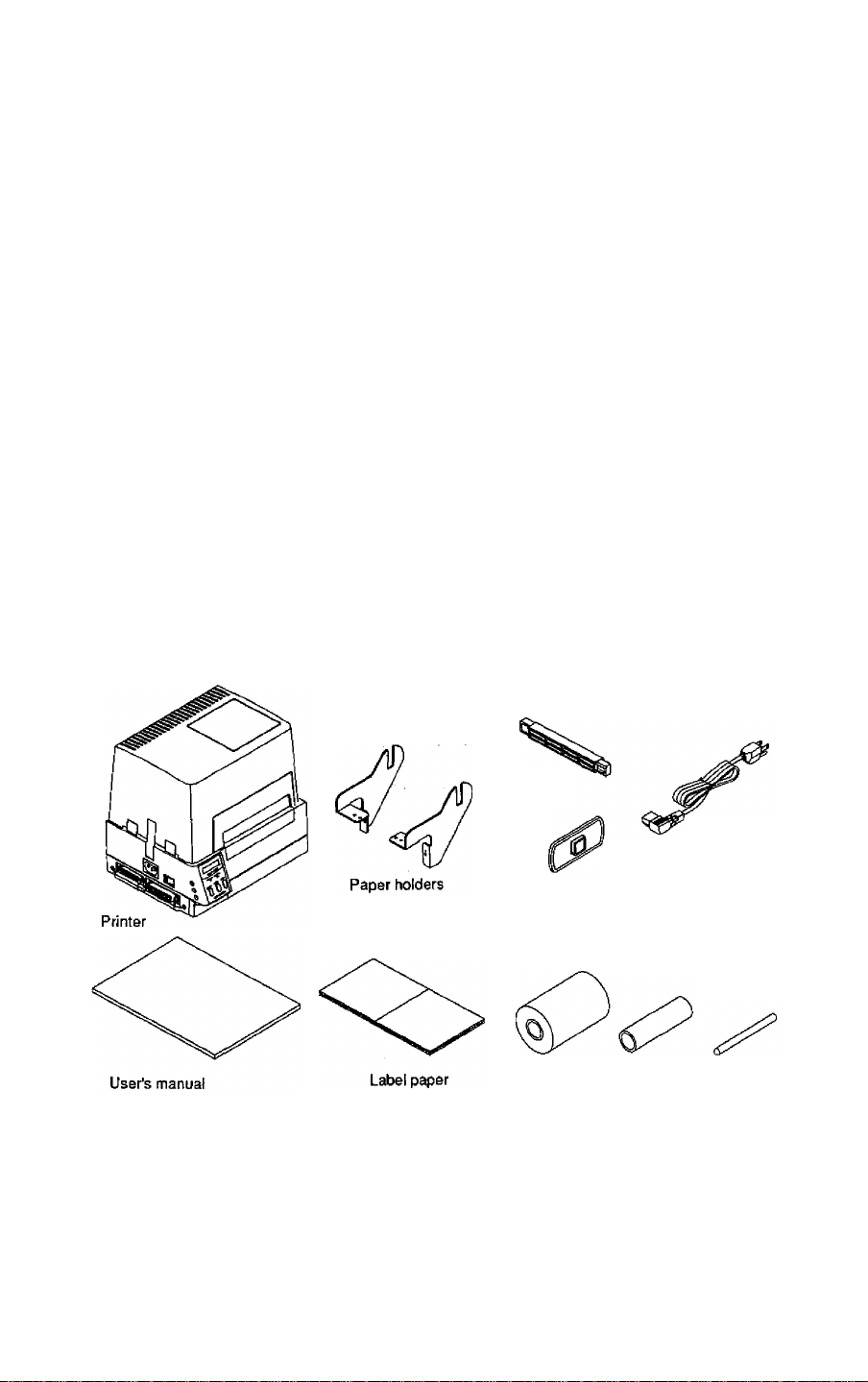
1.1 Confirmation of Carton Contents
/^CAUTION
Be careful when moving or carrying the printer and
when taking the printer out of the carton. The printer
may cause injury or property damage if dropped. Be
sure to hold the printer firmiy when taking it out of the
carton. Do not grip the printer by the foam packing
material which may break, causing the printer to drop.
Check that the following accessories are inciuded with the printer in the carton.
• Printer
1 unit
• Paper holders 1 set
• Power cord 1 pc • User's manual
• Ribbon 1 pc • Paper core
• Screws
4 pcs • Label paper 1 set
1 copy • Roll guide 1 pc
1 pc • Cleaning pen
• Roll holder 1 pc
1 pc
Note: The empty carton and packing materials should be stored for future
shipping of the printer.
1-2
Roll holder
Power cord
Roll guide
Screws (four)
Ribbon Paper core Cleaning pen
Page 15
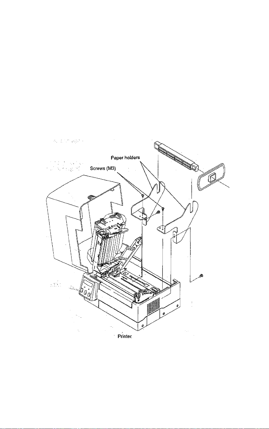
1.2 Installing the paper holders
The roll paper of 4 in diam. {101.6 mm diam.) is set on the back of the printer.
Instailation
1) Open the printer cover.
2) Set the paper holders (accessory) as shown in the figure.
3) Secure the paper holders with screws M3 from the top and M4 from the
back. (Tightening torque; 6kgf-cm)
1-3
Page 16
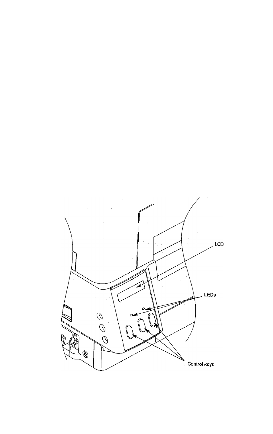
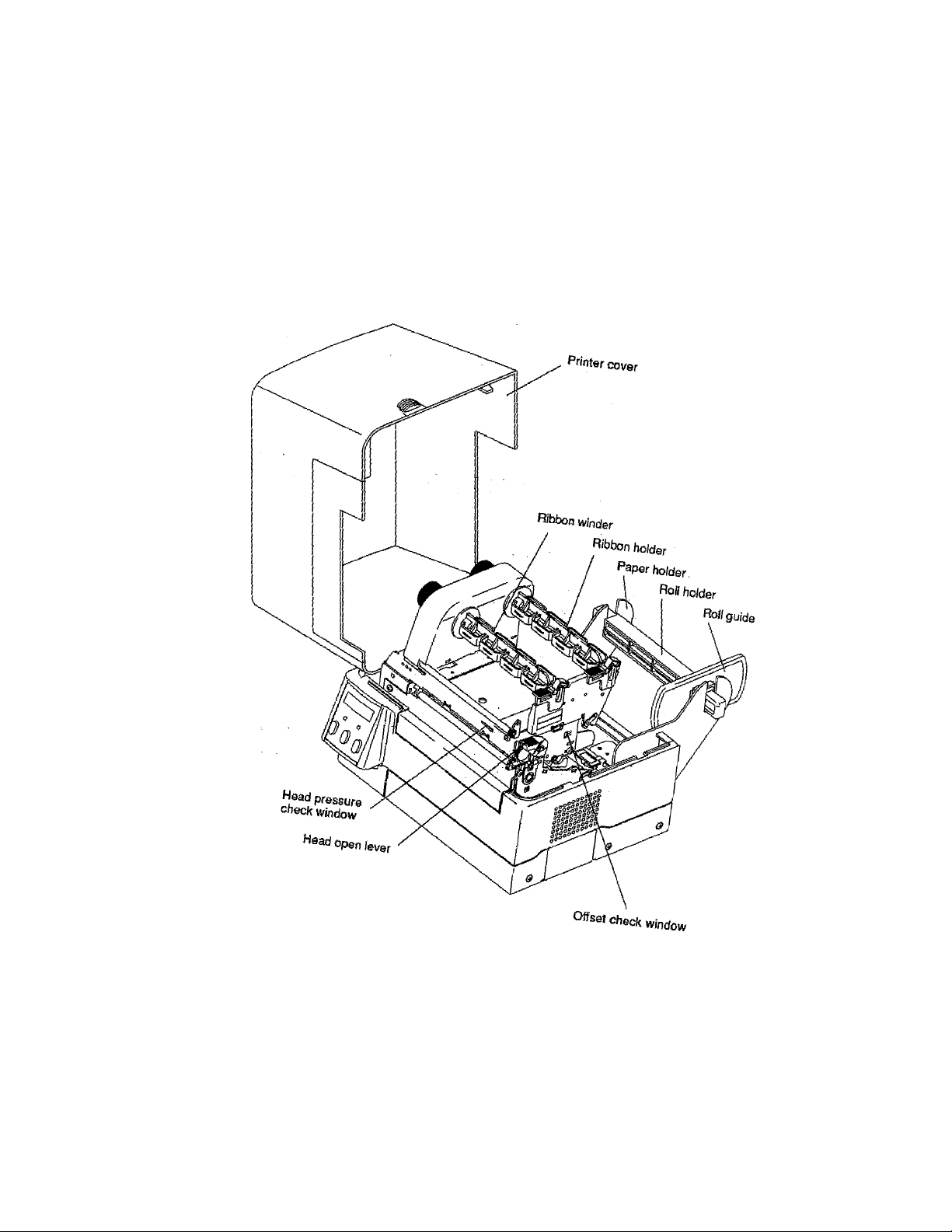
1.3 Names and Functions of the Parts
Front view
Control panel
The control panel is a center of the printer that displays printer .,
messages through the LCD and LEDs,
1) LEDs :
One LED is the power indicator and the other is the error indicator.
2) LCD
Displays the current printer status, configuration settings and errors.
3) Control keys
The Pause, Feed and Stop keys are arranged from left to right and are
used to facilitate printer operating. (For details, see Chapter 2 Control
Panel.)
1-4
Page 17

Inside view
■ Printer cover
Opens to allow loading of the paper and ribbon,
■ Ribbon holder
Holds the ribbon. (See Chapter 3.)
■ Ribbon winder
Winds the ribbon after printing. (See Chapters.)
■ Roll holder
Holds the roll paper.
■ Roll guide
Guide the roll paper to be set on the roll holder. The roll guide can be
adjusted in accordance with the width of the paper. (See Chapter 3.)
■ Paper holders
Hold the roll holder to be inserted in the paper core.
■ Head open lever
Opens/closes the print head. This is used when loading the paper and
ribbon or when cleaning the print head.
■ Offsetyerification window
Facilitates adjusting the print head position to match the thickness of the
paper.
■ Head pressure, verification window
Facilitates adjusting the print head pressure to match the width of the paper
and the paper quality.
(See figure on next page)
1-5
Page 18
1-6
Page 19
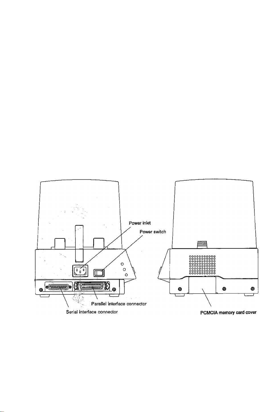
side view
■ Intertace connectors
Connect the interface cables.
■ PCMCIA memory card cover
To protect the PCMCIA memory card from exposure to dust and foreign
matter. To install a PCMCIA memory card, first unhook this cover, then
slide it out.
■ Power switch
Turns on/off the power to the printer.
■ Power inlet
Connects the power cord.
1-7
Page 20
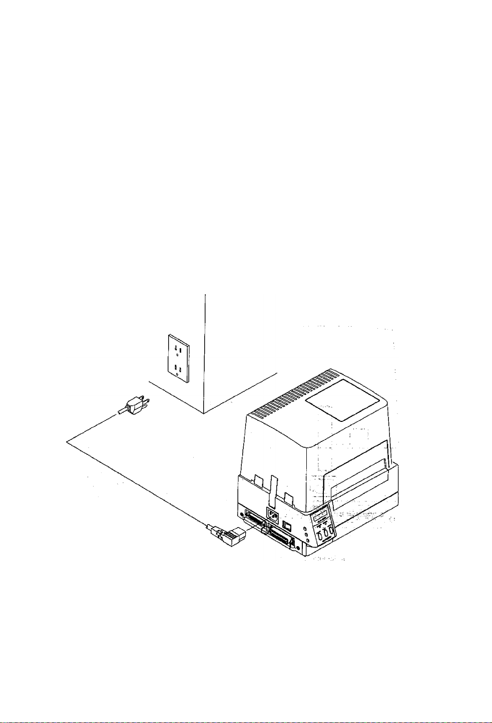
1.4 Connection to Power
CAUTION; Use the three-pin (including grounding) gu.tle{.,. |
A
Connect to power as follows; ■
1) Check that the power switch on the printer is turned off^-c: s?
2) Connect the connector of the power cord to the powerfnlet Smthe printer.
3) Insert the plug of the power cord in the outlet. : ?>.■
Otherwise, you may get hurt by static'eiectricity.
Also, you may get an electric shock wheh^the 'printer
breaks down or short circuit occurs or a ttpunderbolt;
falls. . ^
1-8
Page 21
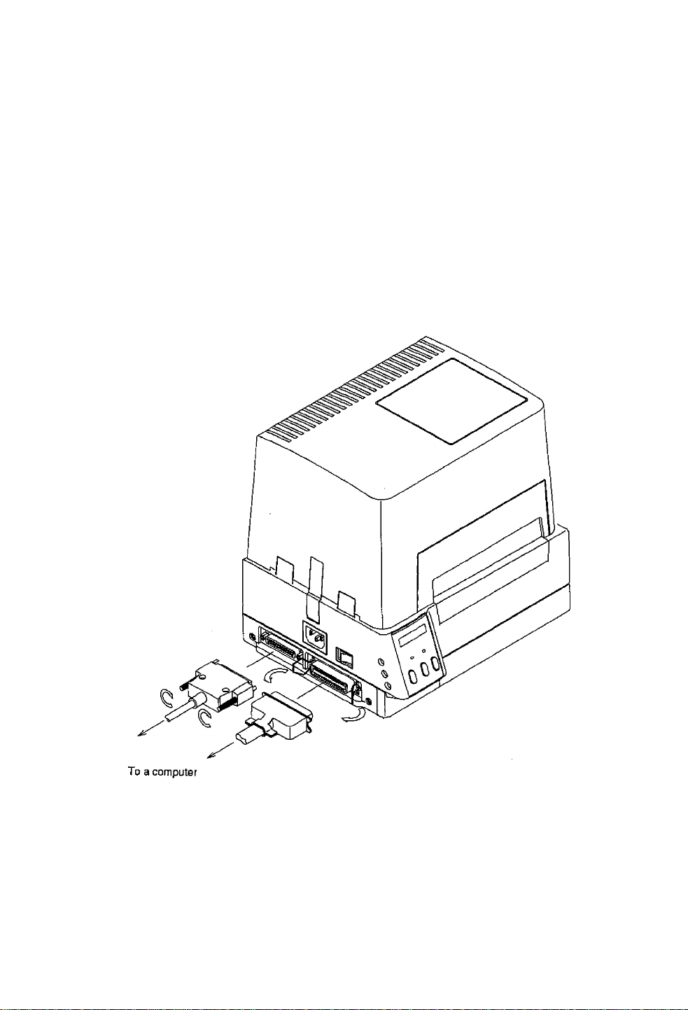
1.5 Connection to a Computer
An interface cable is necessary for connecting the printer to a computer.
Connect the printer to a computer as follows;
1) Check that both printer and computer power switches are turned off.
2) Insert the connector of the interface cable in the interface connector on the
the printer and secure it with lock screws.
3) insert the connector on the other side of the interface cable in the interface
connector on the computer and secure it with lock screws.
1-9
Page 22

1-10
Page 23

Chapter 2
Control Panel
2.1 Control Panel 2-2
2.2 LCD/LED Indications and Adjustment Controls 2-3
2.3 Normal Operating Mode 2-3
2.4 Printer Setup Mode 2-4
2.5 SeH-TestMode 2-4
2.6 System Maintenance Mode 2-5
2-1
Page 24
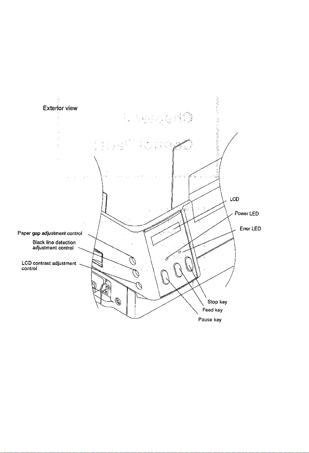
2.1 Control Panel
The control panel consists of the three control keys (Pause, Feed and
Stop), two LED Indicator lights {Power and Error), a LCD message
screen. On the left side of the control panel there are three adjustment
controls (paper gap sensor, black line sensor and LCD contrast).
2-2
Page 25

2.2 LCD/LED Indications and Adjustment Controls
1) LCD
The eight-character LCD screen displays the current printer status,
configuration settings, or an error message.
2) LEDs
Power; Lights when the power is tuned ON.
Error: Lights or blinks when an error occurs.
3) Adjustment controls
The three adjustment controls are used to adjust the paper gap .
(transparent type) sensor sensitivity, black line (reflective type)
sensor sensitivity, and LCD contrast.
2.3 Normal Operating Mode
When the power is turned on, the printer enters the normal operating
mode. The control keys function as follows:
Pause key
Temporarily pauses printing. "Pause" is displayed on the LCD
screen. If pressed during printing, printing will stop after the current
label is printed. Press the Pause key again to resume printing.
Feed key
Advance to the top of the next label. When using continuous paper,
make sure the Sensor selection is set to ContinuP or a Paper error
will result.
Stop key
With this key, the operator can stop and cancel the current print job.
Pressing the Stop key during printing stops the printing immediately,
pressing the.Stop key again cancels the print job. If pressed when
the Error LED is illuminated, the error will be cleared and the printer
will pause. But if the error is not cleared, the Error LED will remain
illuminated. . -
2-3
Page 26

2.4 Printer Setup Mode
The printer enters the printer setup mode when both Stop and Feed
keys are pressed simultaneously. The control key functions at this time
are described below.
Settings of the printer setup mode are stored in nonvolatile memory, so
once they are set, they are remained even when the power is turned off.
[Functions]
Set the print mode seiection, peeling sensor ON/OFF, auto-cutter
ON/OFF etc.
■ Pause key; Selects the mode.
■ Feed key: Selects the mode item.
■ Stop key: Saves settings and returns the printer to normal
operating mode.
Item
---------
;
Direcl-thermal/thermal-
transfer printing
I
Peeling sensor
i
Auto-cutter
4
Tearing
4
Sensor selection
____
_l
2.5 Self-Test Mode
The printer enters the self-test mode when the Feed key is pressed and
held down while turning the printer on.
[Functions]
The printer performs the test print and enters the data dump mode (prints
communication data with ASCII codes). The printer returns to the riormal
operating mode when the power is turned off.
If the Feed key is pressed further for five seconds after the printer has
entered the self-test mode, the test print will be performed in the continuous
paper mode, regardless of sensor selection stored in backup memory.
LCD indication
Direct TM — Transfer
Peel OFF Peel ON
Cut OFF Cut ON
Tear OFF -*■ Tear ON
Edge -* Reflect -- Continu P ■
2-4
Page 27

2.6 System Maintenance Mode
The printer enters the system maintenance mode when the Pause, Feed
and Stop keys are pressed and held down simultaneously while turning
the printer on.
If those keys.are pressed further for five seconds after the printer has
entered the system maintenance mode, the system will be reset and the
settings in the backup mehiory will be reset to the following default
values: . . ^
• RS-232C communication setting
Baud rate; 9600 bps
Data length; 8 bits
• Print mode setting
Print mode: Thermal-transfer printing
• Optional function setting
Peeler: OFF
Cutter; OFF
Ejector: OFF
• Paper sensor setting
Sensor: Transparent type (paper gap detection)
• Compatible model setting
Native: ON
[Functions]
Set the RS-232C communication parameter and enter the paper sensor
sensitivity adjustment mode.
• Selects the mode when the Pause key is pressed.
• Selects the mode item when the Feed key is pressed.
• Stores the selected settings in the backup memory when the Stop
key is pressed and the printer comes on-line.
item
—
Baud rate
Data length
Model
Voltage setting
___
I
9600bps -► 19200bps ^ 38400bps ■ • • 4800bps
8 bits 7 bits
NativeON — NativeOF
PE*.*+V —*■ BL*.**V
LCD indication
□
2-5
Page 28

■ Voltage setting I rri-iJgv
In the voltage setting mode, operate the paper gap and black line
adjustment controls in the follo\wing way:
For the standard paper gap voltage, both TE‘''and'''BL" diSpISybdj-b^^^
the LCD 'screen are set to 3/0 V-BI3 V. ■ . ; i / /: ■ ‘
Setting procedure:
1) Sets only the base sheet peeled off the label
(.For,tfe black line
paper, set it so that black lines are off the paper sensor.)
2) Sets the paper gap level to 3.0 V-3.3 V by operating the adjustment
controls.
2^6
Page 29

Chapter 3
Paper and
Ribbon
3.1 Kinds of Paper 3~2
3.2 Label and Tag Specifications 3-2
3.3 Ribbon 3-6
3.4 Loading the Paper 3-7
3.5 Loading the Ribbon 3-9
3.6 Print Head Offset Adjustments 3-10
3.7 Ribbon Tension Adjustments 3-12
3-1
Page 30

3.1 Kinds of Paper
1) Kinds of paper
A thermal-transfer or direct-thermal printing paper can be used.
The paper must be of high quality. Otherwise, the clear print quality and
the longer life of the print head will not be guaranteed.
2) Type of paper
• Labels (continuous, die-cut, fanfold)
• Tags
• Tickets
Both in-wound and out-wound paper rolls may be used.
3} Size of paper
Width of paper; 25.4 mm-118 mm (1 in-4.65 in)
Thickness of paper: 0.063 mm-0.254 mm (0.0025 in-0.01 in)
Max. printing width; 104 mm (4.1 in)
Max. printing length; 406 mm (16 in)
Max. outer dimension of roll paper:
203 mm (8 in) when using optional roll paper holder
101.6 mm (4 in) when using standard paper holder
4) Inner diameter of paper core
Inner diameter of paper core for roll paper: 38 mm-102 mm (1.5 in-4 in)
Note; The paper core inner diameter for installing the standard paper holders
is 38 mm (1.5 in)
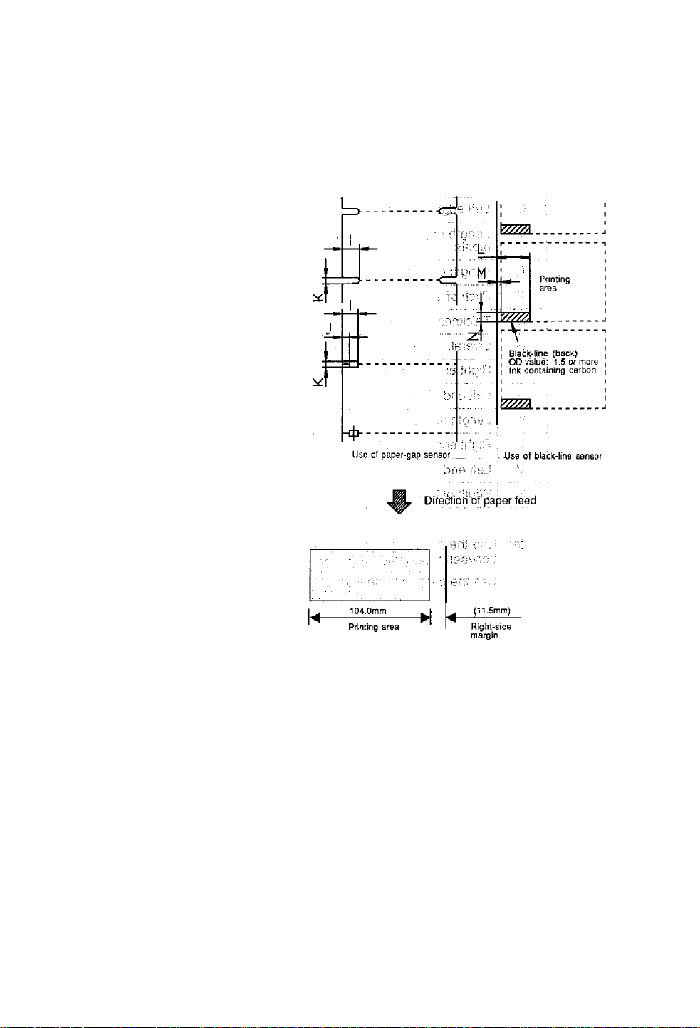
3.2 Label and Tag Specifications
The position of the label or tag is detected by the printer's transparent and
reflective type photosensors.
Transparent type photosensor: Detects paper gaps between labels
Reflective type photosensor: Detects black lines.
■ Paper specifications
For dimensions of the paper gaps between labels, tag (label) notches
and black lines, see the table and figure.
or tag notches.
3-2
Page 31

A
Width of labei
B Width of iiner
c Left edge of label
D-- Length of paper gap between
labels
Minimum value
mm (in)
25.40 (1.0)
25.40 (1.0)
0 2.54 (0.10)
2.54 (0.10)
Maximum value
mm (in)
118.00 (4.65)
118.00 (4.65)
2539.00 (99.96)
E Length, of label
F Pitch of label
Thickness of liner
H
Overall thickness of paper
. 1
Note: Use the paper gap sensor when the paper has paper gaps
Right lend of notch 8.3 (0.32)
Left end of notch
j.:
K
Length of notch 2.54 (0.10)
L Right end of black line
M Left end of black line 0
N , Width of black line
between; labels and black lines.
Use the paper gap sensor for the fanfold.
12.70 (0.50)
12.70 (0.50)
0.06 (0.0025) 0.125 (0.0049)
0.06 (0.0025) 0.25 (0.01)
0
15.00 (0.59)
3.18 (0.125) 17.80 (0.70)
2539.00 (99.96)
2539.00 (99.96)
11 (0.43)
4.7 (0.19)
17.80 (0.70)
—
1.5 (0.06)
3-3
Page 32
Siz© of paper
Label
Gónánubu's^'lpaper ^■
H
Printing area
LU
LL
Use of paper-gap sensor
Label
Label
Label
Notdi detection
Black-line detection
Left-side
margin
3-4
Page 33

Units for specifying position and length
The print position may be specified in either inch or metric system.
Switching between the two systems is accomplished through
software. The print position can be freely designated within the
maximum label size, regardless of which system you wish to use.
■ inch system
Basic unit (point):
The position of each row address (in direction of main scanning) and
column address (in direction of subscanning) is designated in 0.01-inch
units, in case of the 203 dpi head, if the print position changes by 1
point, it changes by 2 dots.
1 point =
100 point =
■ Metric system
Basic unit (point):
The position of each row address and column address is designated in
0.1-mm units. Since a slight difference between the main and
subscanning density and the point value exists, the nearest dot
number to the designated address is selected in one dot (0.125 mm)
units.
1 point =
100 point =
0.01 in (0.254 mm)
0.01 in
1.00 in
0.1 mm
0.1 mm
10.0 mm
2 dots
203 dots
1 dot
SQdots
The basic unit is common to all label format and system level
commands. The label format commands.are used to specify the
position, length, whole screen offset etc. And the system level
commands are used to specify the maximum paper length, home
position offset etc.
3-5
Page 34

Reference points
The reference points are described in the figure. The position of 2.5 mm
from the left edge of the paper is the reference point. The left bottom is
the reference point for thé printed characters and bar codes. The
concept of this reference point is common to such commands as ruled
line and graphic.
Piinling refsrence point
Left end of paper
Paper reference point .
Printing reference point
2.5
-----
Direction of paper feed
Ш Q
n u
О Ш
m J^BCDE
Printing reference point
aODaV LU
Printing reference point
3.3 Ribbon
Size of ribbon:
Width of ribbon: 25.4-114.3 mm (1-4.5 in). The ±10% of the width of the
paper to be used is recommended for the width of the thermal-transfer
ribbon.
Use the inner diameter of 25.4 mm (1 in) for the ribbon paper core.
The ribbon with inking surface rolled inward or outward can be used.
The maximum outer diameter of the ribbon roll is 74 mm (2.9 in).
A single roll of ribbon (360 m) can be used for printing on about two roils
with an outer diameter of 203 mm (8 in).
3-6
Page 35

3.4 Loading the Paper
/^CAUTION
The printer is designed to easily load the paper and ribbon. After
opening the cover, set the register paper as follows;
1) Push down the open lever (1) to have the head open (see the
figure).
Be careful of the edges of the plates so injury or
property damage is possible.
2) Push the lever (3) to have the guide rail upper (2) open.
3) insert the roll holder (4) in the roll paper and roll guide (5) and set
on the paper holder (6). Adjust the roll guide (5) to match the width
of the paper. The roil paper must be positioned into the reference
plane.
4) Slide the moving paper guide (7) to the right end to secure the
paper insertion course.
5) Set the paper as shown in the figure.
6) Align the left edge of the paper with the stationary paper guide (8)
and put the moving paper guide to the edge of the paper so that
the paper does not shift sideways.
7) Push down the guide rail upper until the lever is hooked and lock it.
8) Align the paper with the peeling plate (9) positioning notch and
push down the ribbon bearing flat (10) to close the print head. The
open lever is hooked.
9) Close the cover.
10) Turn on the power to the printer. The LCD screen on the control
panel will show the "On line." Press the Feed key. The paper will
advance to the next label and stop there.
3-7
Page 36

J ìli onibäVJ fi'л
3-8
Page 37
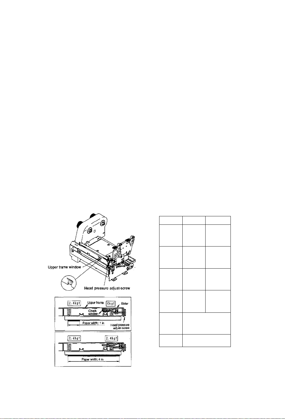
When the print density on the left and right sides is not equal (when the
paper with a different width has been used):
The right head pressure viewed from the front of the panel can be adjusted
with the head pressure adjust-screw. Turning the adjust-screw clockwise
decreases the head pressure and turning the adjust-screw counterclockwise
increases the head pressure. And the condition of the right side of the print
head can be checked through the upper frame window which is iocated at
the front of the printer mechanism unit.
Adjustments
Normally, the left and right head pressure has already been factory-set to
same loads. The check marks of the upper frame window are located at the
right side of the printer viewed from the front of the printer.
Adjustments are needed in the following cases:
1) When the print on the left side is too light, turn the head pressure adjust-
screw clockwise.
2) When the print on the right side is too light, turn the head pressure adjust-
screw counterclockwise.
3) When the paper with a different smali width is used, the contact
between the print head and the platen becomes large, so the stepping
motor will take a heavy load or the print head may scrape the platen.
To avoid this, turn the head pressure adjust-screw clockwise to
decrease the right head pressure.
In addition, adjustments will be useful for preventing the ribbon wrinkling or
the paper skew. For more information, contact our service personnel.
Check
window
f 1 inch
iTh*^
/
Paper widtfi
2 inches
Right head
pressure
0 kgf
0.5 kgf
1 M I
' 1 iTt"
/
3 inches 1 kgf
Trf?
mm"
1 M 1
Vi i”T
\ i j1"
Mil
Note; These values are just tor criteria.
A inches 2A kgf
i
Used for adjustment when
/
ribbon wrinkles or skews
in paper width of 4 inches
Factory setting
3-11
Page 38
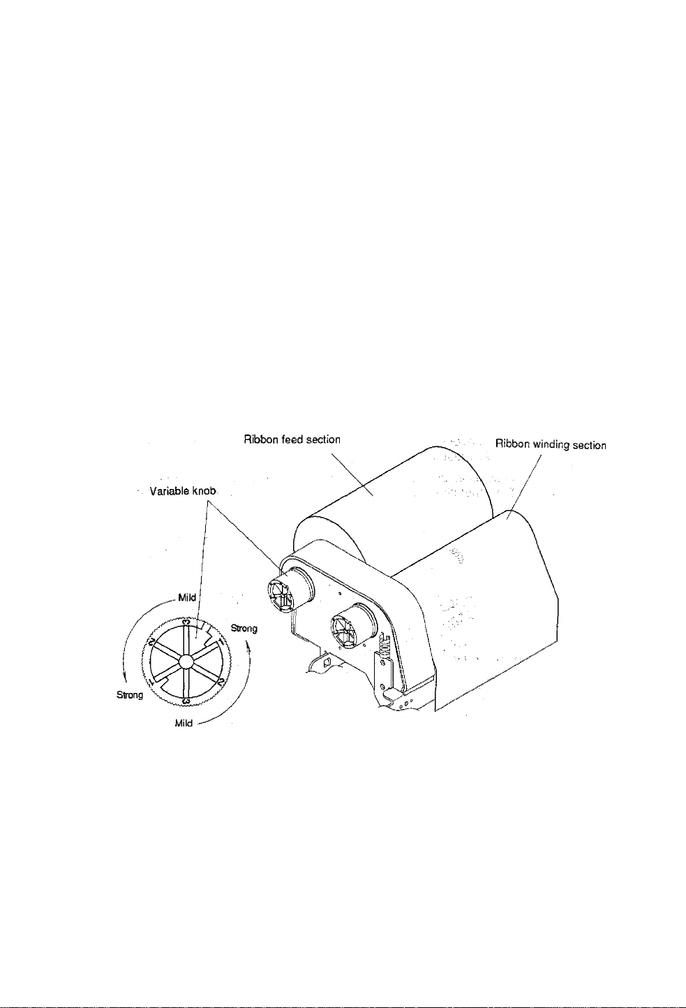
3.7 Ribbon Tension Adjustments
Three kinds of ribbon tension (Strong, Medium and Mild) are available on
each ribbon feed and winding section. Changing the ribbonlerrsion is
accomplished with the variable knobs. Numbers 1,2 and 3'(Strong,
Medium and Mild) are indicated on each variable knob.
■ Adjustments
When the width of the ribbon is 4 in, set it to Strong.
When the width of the ribbon is 3 in, set it to Medium. ’
When the width of the ribbon is 2 in, set it to Mild.
The above is just for reference. The ribbon tension should be adjusted if
the following problems occur:
a) When the ribbon wrinkles, increase the tension.
b) When the ribbon slips, decrease the tension.
3-12
Page 39

Chapter 4
Troubleshooting
4.1 Error Messages 4-2
4.1.1 Error descriptions and indications 4-2
4.1.2 Error indications and corrective actions 4-4
4.2 Power Troubieshooting 4-7
4.3 Paper Feed Troubleshooting 4-8
4.4 Ribbon Feed Troubleshooting 4-9
4.5 Print Troubieshooting 4-10
4.6 interface Troubleshooting 4-11
4-1
Page 40
4.1 Error Messages
When there is a problem with the printer, a buzzer sounds, and the
LED eiTor indicator on the control panel lights. An error message is
displayed on the LCD screen. Error descriptions and corrective
actions are shown below.
4.1.1 Error descriptions and indications
Description
Battery dead (for clock and backup RAM)
Low head temperature
Low PCB temperature
Abnormal head resistance value
Error contents and head information
LCD indication
Battery
CoIdHead
Lights
Lights
Cold PCB Lights
Lights
Head Err
repeatedly displayed
Rank: Rank of head resistance
Rank *“
value
Average: Average of resistance
Ave.***
values (A/D reading value
decimal system)
Maximum: Max. value of resistance
Minimum: Min. value of resistance
Communication error (receive buffer
Max.***
Min.***
OverFtow
Lights
overrun)
Communication error (parity, framing)S/l Err
Communication error (transmit buffer
overflow
Pause key pressed
HostBusy
T.D.Full 3 times
Pause
Lights
Blinks Sounds short
Pause command reception (remote control)Pause
Head overheat OverHeat
Blinks
Cooling
Stop key pressed Stop —
Stop command reception (remote control)
Mechanism head open HeadOpen
Paper end (no paper left)
Cancel
PaperEnd
Lights
Lights
LED Buzzer
Sounds long
Sounds long
Sounds long
Sounds long
Sounds long
Sounds long
— —
— —
Sounds short
3 times
Sounds short
3 times
— —
Sounds short
3 times
Sounds short
3 times
(continued)
4-2
Page 41

Description
LCD indication LED
Paper out (paper position can't be detected)
Error contents and sensor information
PaperErr
repeatediy dispiayed
M command: Sets length for detection
miss checking with system
MCMND
command M
Maximum: Max. value of sensor
reading voltage
Minimum: Min. vaiue of sensor
reading voltage
Max*.**V
Min*.*‘V
Lights
Buzzer
Sounds short
3 times
Ribbon end RibbonOut
PCB overheat
OverHeat Lights
Lights Sounds short
(PCB or sensor abnormality)
Motor overheat
MotorHot
Blinks
Cooling
Option board abnormality
Auto-cutter abnormality
OP Err
Cut Err
Lights
Lights Sounds short
(such as poor engagement)
ROM checksum error ROM Err Lights
RAM checksum error
RAM Err
Lights Sounds long
System error (such as timer or CPU running
out of control) System is protected and all
printer functions are stopped.
3 limes
Sounds short
3 times
Sounds short
3 times
Sounds short
3 times
3 times
Sounds long
4-3
Page 42

4.1.2 Error Indications and corrective actions
LCD indication
Battery
Description
Battery dead
ColdHead Low head
temperature
ColdPCB Low PCB temperature
Head Err
Abnormal head
resistance vaiue
Corrective actions
Automatically returned after displaying the error for a
certain time.
Change the lithium battery (CB203.2).
Note: Contact our service personnel for
replacing the battery
If the battery runs down, the real-time clock will stop
and the contents of the memory switch will be lost.
Automatically returned after displaying the error for a
certain time.
Raise the temperature around the printer.
Print density becomes low and print quality
becomes inferior when the head temperature is low;
Automatically returned after displaying the error for a ,
certain time.
Raise the temperature around the printer.
Print density becomes low and print quality
becomes inferior when the head temperature is low.
Check the contents and clear with the Stop key.
Replace the print head.
OverFlow Communication error
(receive buffer
overrun)
S/l Err Communication error
(parity, Iraming)
HostBusy Communication error
T.D.Full
(transmit buffer
overflow)
Stop Stop key pressed
If the Pause key is pressed, the printing will resume.
(continued)
Print quality is affected in the section with abnormal
head resistance value.
Check the contents and clear with the Stop key.
Correct the communication control system or faulty
communication cable.
Check the contents and clear with the Stop key.
Correct the communication parameter or faulty
communication cable.
Automatically returned if the computer receives data
and the buffer becomes empty.
Enters the pause after displaying the stop by the
Stop key.
If the Stop key Is pressed again, the stored printing
contents will be lost and the printer will be "on line.”
4-4
Page 43

LCD indication
Description
Corrective actions
Pause
Pause
OverHeal
Cooling
MolorHot
Cooling
Cancel
HeadOpen
(continued)
Pàuse key pressedPress the Pause key once again to resume printing.
If the Stop key is pressed, the stored printing
contents will be lost and "on tine" will turn on.
Pause command
Same as above.
reception
(communication
control)
Head overheat Wait until the head temperature goes down. When
the temperature becomes low, the remaining
printing resumes.
Motor overheat
Wait until the motor temperature goes down. When
the temperature becomes low. the remaining
printing resumes.
Stop command
reception
Displays the stop by the stop command, discards
the remaining printing contents, and enters the
pause.
It the Pause key is pressed, the printer will be "on
line."
Mechanism head
Close the mechanism head.
open
4-5
Page 44

LCD indication
Description
Corrective actions
PaperEnd
PaperErr
Paper end (no paper
left)
Paper out (paper
position can't be
detected)
Install the paper.
Check the contents and clear with the Stop key.
Correct the faulty setting of the paper detection
(paper gap, black line, continuous paper).
Correct the faulty parameter tor paper (max. length,
continuous paper).
Adjust the sensor or change for the paper that can
accept the paper position detection.
Specify the length of the detection miss checking
with the M command.
When the paper position can't be detected during
paper feeding by the specified length, it is judged
error. Generally specify the length about three
times the label length.
In case of the continuous paper, specify the label
length with the C command.
Difference between the maximum and minimum
values of the sensor reading voltage is 0.8 V or
more.
Sensor can be adjusted and paper characteristic
(voltage verification) can be verified with the
Maintenance mode.
RibbonOut
Ribbon end Check the contents and clear with the Stop key.
Overheat PCB overheat
OP Err Option board
abnormality
Cut Err
Auto-cutter
abnormality (such as
poor engagement)
(continued)
install ihe ribbon.
Check that the ribbon is wound properly.
Correct the print mode (direct-thermal or thermaltransfer) setting failure.
Turn off the power and reset the printer. If this
recurs, contact our service personnel.
Turn off the power and reset the printer. If this
recurs, contact our service personnel.
Check the contents and clear with the Stop key.
If this can't be cleared, turn off the power and
remove foreign matter from the auto-cutter.
If this recurs, contact our service personnel.
4-6
Page 45

LCD indication
Description
Corrective actions
ROM Err ROM checksum error
RAM Err RAM checksum error
System error (such as
timer, or CPU running
out of control) System
is protected and the
printer is reset
4.2 Power Troubleshooting
Pfoblëm Cause and remedy
No power éveil with
power switch turned ON.
Power cord is not
properly connected to
the outlet.
Power cord is not
properly connected to
the power inlet.
Turn off the power and reset the printer. If this
recurs, contact our service personnel.
Turn off the power and reset the printer. If this
recurs, contact our service personnel.
First protect the system, then reset the printer.
-> Turn off the power switch and
properly reconnect the power
, cord to the outlet.
Turn off the power switch and
properly reconnect the power
cord to the power inlet.
Input voltage is hot
correct; input voltage is
greater or less than the
rated voltage.
Proper RS-232C cable is
not used.
4-7
Set input voltage within the
rated voltage (puncture voltage
may occur. Contact our senrice
personnel).
Turn off the power switch and
unplug the Interface cable.
Check that power is delivered by
turning on the power switch and
use the proper RS-232C cable.
Page 46

4.3 Paper Feed Troubleshooting
Problem
Paper doesn't feed.
Paper path is wrong.
Cause and remedy
Mechanism head is open.
Paper skew. Paper end is not in contact
with the paper guide.
Roll guide is not in contact
with the roll paper.
Head pressure is not proper. Adjust it with the offset
Paper doesn't align with
Setting mode is not proper.
the print position.
Paper gap (black line) sensor Adjust the voltage of the
adjustment failure.
• Transfer data is abnormal.
-> Use the proper path.
-> Close the mechanism head.
Slightly push the paper
guide against the paper
end.
Slightly push the roll guide
against the roll paper.
adjust-screw according to
the width of the paper.
Check whether the setting
mode is the paper gap or
black line detection and if it
is riot prpperi change it.;..
paper gap and black line
sensor in the system
maintenance mode.
If the contents of the
transfer data are not set
properly, set them ag^n.
4-8
Page 47

4.4 Ribbon Feed Troubleshooting
Problem
Ribbon is not wound.
Printing continues even If
ribbon is out.
Ribbon wrinkles.
Cause and remedy
Ribbon path is wrong.
Direction of ribbon winding is
->
Use the proper path.
Set it to the right winding
reverse. direction.
Tension of ribbon winding is
Set it properly.
not proper.
Print mode is the direct-
thermal.
Tension of the ribbon holder
Set It to the thermal-transfer
if necessary.
Set H properly.
and winder is not proper.
Print density (heating factor)
is not proper.
Correct the parameter of the
Hnn command in the
printing contents definition
mode.
Angle of ribbon guide bar is
not correct.
Adjust the ribbon guide bar.
Contact our service
personnel. Note: If a
narrow paper is used, the
ribbon may wrinkle. To avoid
this, decrease the right head
pressure with the head
pressure adjust-screw.
4-9
Page 48

4.5 Print Troubleshooting
Problem
Printing doesn't start.
Power to the printer is off.
Cause and remedy
Printer is not properly
connected to a computer.
Printer setting is not
proper.
Missing ali lines. Print head connector
connection failure.
Paper and ribbon are not
set properly.
Partially dropouts. Print head is dirty.
Platen roller is dirty.
Tu rn 0 n th e power switch.
if power is not still turned on,
follow the steps in the Power
Troubleshooting.
Turn off the power switch and
connect it properly.
Correct the printer setting.
-> if the print head connector is
not properly connected, insert
it correctly.
-> Set them properly.
-> Check the print head
heating element for dirt, if
it's dirty, wipe the surface of
the print head heating
element with a soft clean
cloth soaked in ethylalcohol
etc.
Remove any dirt or label or
tape on the platen.
(continued)
Note: if it can't be removed,
contact our service
personnel for general
maintenance.
4d0
Page 49
Factory or reseller (dealer) options:
5.1 Auto-Cutter Unit 5-2
5.2 Peeler Unit 5-2
5.3 Adjustable Sensor 5-2
User options:
5.4 PCMCIA MenfioryCaid 5-3
5.5 8-in Size Roll Paper Holder 5-4
5-1
Page 50

5.1 Auto-Cutter Unit
The auto-cutter unit that has been installed on the printer will be available.
See the operation manual of the auto-cutter for details.
Specifications
Cutting method:
Max. thickness of cut paper:
Min. length of cut paper:
5.2 Peeler Unit
The peeler unit that has been installed on the printer will be available.
See the operation manual of the peeler unit for details.
Specifications
Width of paper:
Max. diameter for roll paper:
Inner diameter for roll paper:
Min. length of label:
Thickness of paper:
Thickness of liner of label;
Unusable paper:
Circle cutter
0.01 in (0.25 mm)
1.0 in (25.4 mm)
1^.65 in (25.4-118 mm)
8 in (203 mm)
4 in (102 mm), min.
1 in (25.4 mm)
0.0067 in (0.17 mm), max.
0.0027 in (0.07 mm), max.
Special paper (Whitepet etc.) or too
flexible and easy-to-jam paper
5.3 Adjustable Sensor
The adjustable sensor that has been installed on the printer will be
available. See the operation manual of the adjustable sensor for details.
I
Specifications
Adjustable sensor travel: 59 mm (2.3 in) from the left edge of the paper
(reference position of setting paper).
5-2
Page 51
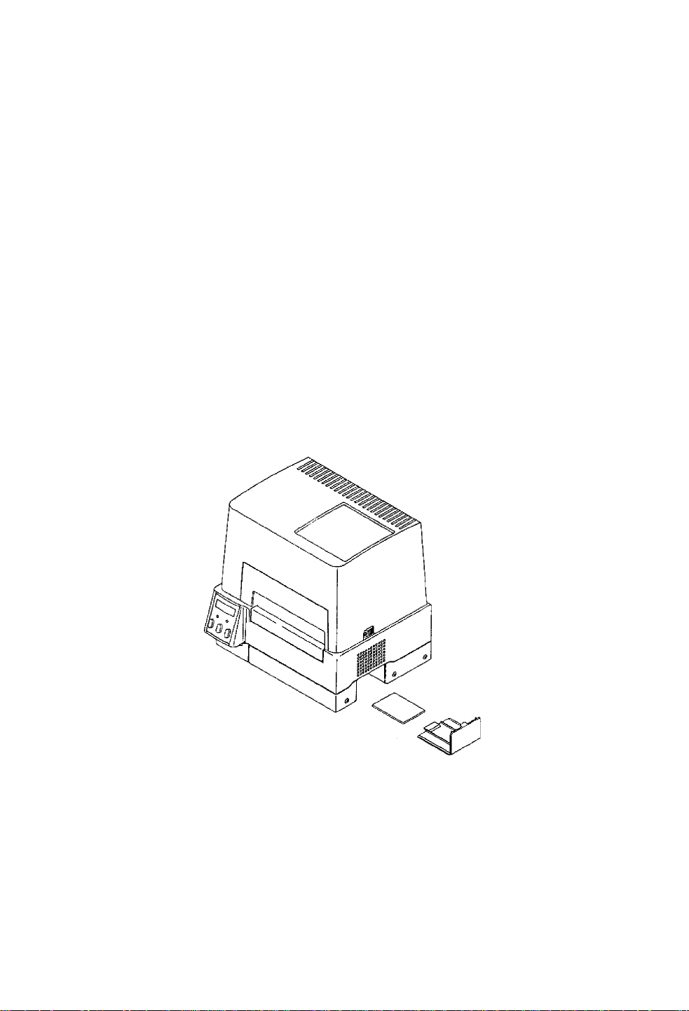
5.4 PCMCIA Memory Card
The PCMCIA memory card is used to:
1} Store the print format files. Data in the field register area can be
stored and loaded,
2} Store graphic data. For example, graphic data such as a corporate
logo can be stored and recalled from the PCMCIA memory card and
printed.
Note: The maximum size of storing graphic data is 256K bytes.
3) Store downloaded HP Soft fonts.
■ Installation
1) Turn off the power to the printer.
2) Remove the PCMCIA memory card cover at the bottom of the printer
(see figure).
3) Insert the memory card (make sure the card is not inverted).
4) Replace the PCMCIA memory card cover.
Notes: * Before use, carefully read and understand the instructions
regarding the PCMCIA memory card.
• Never try to insert or remove the PCMCIA memory card
before the power to the printer is turned off.
• Always close the PCMCIA memory card cover to keep out
dirt.
• If the PCMCIA memory card write failure occurs, check it
with the test command (STX.w). (Also, check the write
protection switch of the PCMCIA memory card.)
5^3
Page 52

5.5 8*in Size Roll Paper Holder
8-in size roll paper holder
• Max. outer diameter: 8 in (203 mm)
• Paper core inner diameter: 1.5 in-3 in (38 mm-76 ram)
5-4
Page 53

Chapter 6 Specifications
6.1 Basic Specifications 6-2
6.2 Interface 6-5
6.2.1 Serial interface system configuration 6-5
6.2.2 Parallel interface system configuration 6-6
6.2.3 RS-232C loopback test 6-7
6.2.4 RS-232C protocol 6-7
6.2.5 Interface pin assignment 6-9
6.3 Outline of Command System 6-11
6.4 Example of Connection to a Computer 6-12
6.5 Tear-Off Function 6-13
6.5.1 Turning Tear ON/OFF 6-13
6.5.2 Tear-off when printing 6-13
6.5.3 Tear-off when feeding 6-14
6.5.4 Tear-off and type of data 6-15
6.5.5 Cut position adjustments 6-15
6.5.6 When '1nnn" command is executed
while tear-off fu notion is OFF 6-16
6.5.7 Priority order &16
6-1
Page 54

6.1 Basic Specifications
Item
Printing
Direct-thermai or thermal-transfer
Description
203 dpi (8 dots/mm) print head
(Main scanning line density: B dots/mm)
(Subscanning line density: 8 lines/mm)
Max. printing width: 4.1 in (104 mm)
Max. paper width: 4.65 in (118 mm)
Max. printing length: 32 in (812 mm)
Printing speed 2-4 inches/second in one-inch units
Print mode Batch mode: Normal printing (single or multi sheets)
Peeling mode: Label peeling off the base sheet after printing
Cut mode: Cutting and printing by the specified number of
sheets (label feeding back enabled)
Tear-off mode: Paper feeding back to the printing start position
after cutting
Bar code generator
One-dimensional bar code:
• Code 3 of 9
• UPC-A
■ UPC-E
• ITF14
• Telepen
• EAN-13 (JAN-13)
• Interleaved 2 of 5
• ITF16
• Code 128
• Codabar (NW-7)
HIBC (Modulus 43-used code 3 of 5)
• EAN-8 (JAN-8)
lnt2of 5 (Modulus 10-used
Interleaved 2 of 5)
• Plessey
• Code 93
CASE CODE
UPC2DIG ADD
• UPC5DIGADD
Two-dimensional barcode:
• UPS Maxi Code
• PDF-417
• QR Code
6-2
Page 55

Hem
Description
Standard fonts
Media sensors
Paper
Font No. 0-6 system font {alphanumeric and European font)
Font No. 7-8: OCRtA OCR-B
Font No. 9: CG Triumvirate smooth font; 6 pt, 8 pt, 10 pt, 12 pt, 14 pt.
18 pt, 24 pt, 30 pt, 36 pt. and 48 pt.
Character set in accordance with code page 850
Transparent type sensor;
Detects paper gap between labels, tag notch and paper out
Reflective type sensor:
Detects black line on back of paper and paper out
Paper top end position (home position} adjustable with software
Label peeling sensor (optional)
Type of paper:
Roll or fanfold type
(continuous label paper, die-cut label paper, tag
paper and continuous ticket paper)
Kinds of paper;
Max. paper width:
Min. paper width:
Max. printing length:
Direct-thermal or thermal-transfer paper
4.65 in (118 mm)
1 in (25.4 mm)
32 in (812 mm)
Ribbon
Min. printing length:
Max. paper thickness:
Min. paper thickness:
Roll paper diam.:
0.500 in (12.7 mm)
0.01 in (0.254 mm)
0.0025 in (0.063 mm)
max. outer diam.: 4 in (102 mm); Standard
8 in (203 mm); Optional
paper core: 1.5-4 in (38-102 mm)
Print density:
Width:
Length;
Max. outer diam. :
Adjustable with software
Freely set between 1.0-4.5 in (25.4-114 mm)
1180 ft (360 m). max.
2.9 in (74 mm)
Paper core inner diam.; 1 in (25.4 mm) ±0.01 in (0.254 mm)
6-3
Page 56

Item
Description
Communication
interface
Indications, keys
and switches
• Serial: RS-232C)
• Parallel: Centronics
• LEDs: Power and Error
• LCD: Displays printer status, error contents,
mode switch contents, etc
• Control panel keys: Pause, Feed and Slop
■ Mode switch: Parameter setting for switching
between direcHhermal and thermal-
transfer, communication etc.
• Head up detection switch
• Power switch
Options By factory or reseller (dealer):
■ Aulo-culter unit • Peeler unit ■ Adjustable sensor unit
By user:
• 8-in size roll paper holder • PCMCIA memory card
Appearance and
• Height: 9.3 in (235.1 mm)
weight
• Width: 9.6 in (245 mm)
Power
Environment
• Depth; 11.4 in (289.8 mm)
• Weight: 11.2 lbs (5.1 kg) ;
• Input voltage 120V: -10%+6%, 2.5A, 60Hz (U.S.A., Canada)
• Input voltage 220V-240V: -lo%+6%, 1.2A, 50/60Hz (Europe)
■ Operating conditions: Temperature: 5-35°C (41-95°F)
Humidity; 30-80% (noncondensing)
• Storage: Temperature: -20-60°C (-4-140®F)
Humidity: 5-85%
• Ventilation: Convective circulation. Air vent be away from
wall etc (to prevent fire)
• Dust: Free from conductive or corrosive matter
6-4
Page 57
6.2 Interface
The printer is connected to a computer and prints labels according to the
commands from the computer.
Two methods of interface with a computer are as foliows:
6.2.1 Serial interface system configuration
Serial interface: RS-232C (standard)
Serial interface specifications
Method
Asynchronous serial interface
RS-232C
Connector
Protocol control
Receive buffer size
DSUB 25-pin
XON/XOFF and CTS/DTR
12K bytes
Receiving data stops when the remaining buffer reaches 2K
bytes and resumes when the remaining buffer reaches 4K bytes
Baud rate
Bit length
300, 600, 1200, 2400, 4800, 9600, 19200, 38400 bps
7-or 8-bit
(Select 8-bit length when using Kana or Kanli)
Stop bit
Fixed
When printer receives data, stop bit is fixed at 1, and when
printer transmits data, stop bit is fixed at 2, But computer can
transmit and receive data, regardless of stop bit at 1 or 2
Parity
Non
6-5
Page 58

6.2.2 Parallel interface system configuration
Parallel interface; Centronics (standard)
Parallel interface specifications
Method 8-bit parallel
Connector
Synchronous
36-pin unphenol type
Strobe pulse
system
Handshaking ACKNLG and BUSY signals
Signal level TTL
6-6
Page 59

6.2.3 RS-232C loopback test
After connector wiring as shown tn the figure, turn on the test mode.
The printer will receive data that has been transmitted by printer itself
and the test of receiving and transmitting data will be performed.
6.2.4 RS-232C protocol
(1) X-ON/X-OFF system (see figure)
This is a control system in which the data transmission request
signal (X-ON (11H) code) and the data transmission stop request
signal (X-OFF (13H) code) are output.
Requirements of output of X-ON code:
• When the power is switched to ON
• When the remaining buffer is less than 2K bytes, and after
outputting the X-OFF, the remaining buffer is more than 4K bytes
Requirements of output of X-OFF code:
• When a printer error occurs
• When the remaining buffer is less than 2K bytes
Fig. Loopback test
6-7
Page 60

Receive buffer size = 32K bytes
4K bytes
Note: Even if each code is ready for output, the same code cannot be
transmitted twice successively (except when the power is turned
on or the printer is reset from the controi panei).
Fig. Buffer in use
(2) Ready/Busy system (see figure)
Requirements of DTR “Ready (High)":
• When the printer is "on line."
• When the receive buffer is more than 2K bytes.
However, when the remaining buffer is more than 2K bytes and the
DTR signal is Busy (Low), the printer keeps a "Busy (Low)” level until
the remaining buffer is 4K bytes. .. .. . .
Requirements of DTR "Busy (Low)":
• When a printer error occurs
• When the printer enters the pause
• When the remaining buffer is less than 2K bytes. '
6-8
Page 61

6.2.5 Interface pin assignment
Serial and parallel interface pin assignment tables are shown below.
■ Serial interface pin assignment table
Pin No.
1
2 TXD
3
Signal Input/Output Description
F.GND
- Frame ground
Output RS-232C output data
RXD
Input
RS-232C input data
4 RTS - RS-232C (pull up to +5V with 2 Ki2)
5
CTS Input RS-232C data transmission on
computer enabled
6 NC -
S.GND -
7
8 NC -
NC -
9
10
11
12 NC
13
14
15
NC
NC -
S.GND - Signal ground
-H5VDC
NC 16 NC
17 NC
-
- Not connected
- -h5 V (max. load 100 mA)
-
-
Not connected
Signal ground
Not connected
Not connected
Not connected
Not connected
Not connected
Not connected
Not connected
18
19
20
21
22 NC -
23
NC
NC
DTR Output RS-232C data transmission on
NC -
NC 24 NC
25 NC
- Not connected
-
Not connected
printer enabled (Busy)
Not connected
Not connected
Not connected
- Not connected
- Not connected
6-9
Page 62

Parallel interface pin assignment table
Pin No. Signai Input/output
1
STROBE
Input Strobe signal for reading 8-bit data
Description
2-9 DATA1-8 Input 8-bit parallel signal
10
11
ACKNLG
BUSY
Output 8-blt data request signal
Output Signal showing printer busy
12 PERROR Output Signal showing paper out
13 SELECT
Output Signal showing printer "on line”
(printing) or "off line" (pause)
14
AUTOFD
15 NC
16
S.GND -
17 FGND -
18
P.L.H
Input
-
Output
Invalidness (ignorance)
Not used
Signal ground
Frame ground
Signal showing peripheral logic high
(pull up to +5V with 1.2 Kii)
19-30
31
32
33-35 NC
GND
INir
FAULT
-
Ground for twisted pair return
Input Printer reset
Output Signai showing printer error
- Not used
36
SELECTIN
Input
Invalidness (ignorance)
6-.10
Page 63

6.3 Outline of Command System
For details ^out command system, see the Command Reference
separately available.
Commands for this printer consist of a string of ASCII codes and end
with "CR" (decimal: 13, hex: OD). Commands are generally classified
into two types, system-level commands and label format commands.
System-level commands are used for system-level operations such as
printer status output, sensor selection and memory card maintenance.
On the other hand, label format commands are used for.definition of
printing.contents such as character data, bar code data, printing speed,
and print density.
System-level commands start with ASCII "SOH" or "STX."
Commands which start with "SOH" are required for real-time execution.
When received, they are executed immediately even during printing.
Commands which start with "STX" enter the buffer area once and then are
executed in the order of data reception.
L^el format commands end with "CR", following the system-level
commands "STX" + "L."
System-level commands Commands to start with "SOH"
start with "SOH" or "STX"
Executed immediately after receiving data
(e.g. printing stop, printer status output etc.)
Commands to start with "STX"
Executed in sequence after inputting into the
receive buffer
(e.g. sensor switching, memory card maintenance
etc.)
"STX" -h "L" i t "E" (with printing)
"X" (without printing)
Labe! format commands
end with "CR"
Print parameter control
Character data definition commands
Bar code definition commands
Graphic commands
Other commands
6-11
Page 64

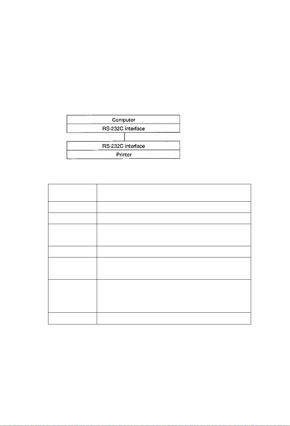
6.4 Example of Connection to a Computer
When RS-232C is used:
IBM PC compatible
Communication control: XON/XOFF or CTS/DTR
”PC”
(DB25P)
F.GND
TXD
RXD
GTS
S.GND 7
DSR 6
DTR
"PC
(DB9P)
NC
H
20
Printer
(DB25P)
F.GND
1
2
3
5
1
RXD
3
TXD
2
DTR (Ready/Busy)
20
S.GND
7
4 RTS
5 GTS
Printer
(DB25P)
1 F.GND
TXD
RXD 2
GTS
S.GND
DSR
DTR
RXD
3
8
5
6
4
6-1 2
3
2 TXD
20 BUSY
7 S.GND
4
RTS
5
GTS
Page 65

6.5 Tear-Off Function
The tear-off function eliminates the waste of labels when tearing manually. It
allows the paper to automatically advance to the tear position after printing.
When this function is turned on, the paper will be fed to the manual tear position
after printing. The printer will feed back paper to the start print position when
the next print job is sent.
If data is transmitted continuously from the computer, the tear-off function will be
suppressed to increase throughput.
6.5.1 Turning tear ON/OFF
Tear can be turned to ON or OFF from the control panel. Default is OFF.
Indications on the control panel are as follows;
Tear-off function Invalid
LCD indication
6.5.2 Tear-Off when printing
if set, the tear-off function will start if no print data is transmitted for 0.5 second
after printing, if data is transmitted continuously from the computer, the tear-off
function will be suppressed.
Tear-off is only performed for the final label of each batch processing.
(The tear-off function is not performed until the specified number of print sheets
is completed.)
"Tear OFF"
Tear-off function valid
"Tear ON"
6-13
Page 66

The p^er is fed to the tear position
Paper position sensor
Tear-off function will start if no
data is sent for 0.5 second after
printing
Paper is fed to the position
where manual tearing is
possible
When manuai tearing is needed, tear the iabel at this time.
Performs next label printing.
When next print data is transmitted from the computer, the printer
feeds back paper to the previous print completed position and
resumes printing.
1
6.5.3 Tear-off when feeding
• If no print data is transmitted for 0.5 second after feeding, the tear-off
function wiil start. If the Feed key is pressed again before starting the
tear-off function, the printer will start feeding without tear-off function.
Paper is fed to the tear position
When manual tearing is needed, tear the iabei at thi.s time.
Performs the next feeding or label printing
If the Feed key is pressed or next print data is transmitted from the
computer, the printer feeds back paper to the previous print
completed position and resumes feeding or printing.
Paper is fed back to the
previous print completed
position and printing resumes
6-14
Page 67

6.5.4 Tear-Off and type of data
When the tear-off is valid, the printer monitors the print data for 0,5
second during or after printing, if print data is transmitted within 0.5
second during or after printing, the printer will start the next printing
without tear-off. (When data is received during printing, the time of
monitoring 0.5 second is not inserted.)
The commands for this printer are mainly classified into the immediately
execution commands starting with "SOH" and the sequentially execution
commands starting with "STX." In tear-off function, only the sequentially
execution commands related to print processing contents are monitored
but the immediately execution commands are not monitored.
Therefore, even if the printer status or the remaining number of print
sheets is read out by using the immediately execution commands during
printing, the tear-off will be performed after printing. On the other hand, if
the sequentially execution commands are used during printing or within
0.5 second after printing to transmit print-related data, the printer will start
the next printing without tear-off. (For details, see the Command
Reference.)
6.5.5 Cut position adjustments
• The cut position can be set with the “fnnn" of the system-level
commands. When the tear-off function is turned on, the following
initialization value is set in the printer.
Initialization value: fnnn = f701 (70.1 mm)
The values higher or lower will increase or decrease the amount of
feeding in the tear-off function.
Print head
1
Tear-off
fnnn
Reference point
Onnnn
\\i
Onnnn: Paper position
fnnn:
fnnn <= Onnnn
fnnn > Onnnn
specifying
Feed position
specifying
Feeding or feeding back is
not performed
Feeding or feeding back is
performed
6-1 5
Page 68

Parameter initialization values . ' ■ : ;
initialization values for printing and peeling positions are described below.
Unit: rnrh (inch)
Minimum
value
12.7
(0.5)
Print position
(Onnnn, form offset)
Norma!
printing
55,9
(2.2)
Autocutter
55.9
(2.2)
. Peeling
55.9
(2.2)
Tear-off
55,9
(2.2)
Cut position
(fnnn)
If values lower than the minimum values are set, the initialization values will be
set instead. {For values with mark *, see the separate option, operation
manuals.)
55.9
(2.2)
*
*
70.1
(2.8)
12,7
(0.5)
6.5.6 When "fnnn" command is executed while tear-off function is OFF
Even with the tear-off function OFF, the paper will be fed to the "fnnn“-
specified position after printing if an "fnnn > Onnnn" value is set by using the
"fnnn" command.
This function will be used for such case as another device is incorporated in
the printer.
To perform operation with the FARGO, the following is different from those in
the tear-off function ON:
• The paper is fed immediately after printing, whereas, in the tear-off
function ON the paper is fed when no data is transmitted for 0.5 second
after printing.
However, if the next print data is transmitted during printing, the printer will
start the next printing without feeding or feeding back.
6.5.7 Priority order
The following three functions (optional) cannot be performed simultaneously.
If commands for three functions are received simultaneously, the printer
will operate in the following priority order:
1st: Auto-cutter
2nd: Peeler
3rd: Tear-off function
6-16
 Loading...