

Page 1

CITIZEN
User's Manual
Model : CBM-292/293
Line Thermal
Panel Printer
Rev 1.00 Newly issued on 27.July.1998
JJJJaaaappppaaaan
IIIInnnnffffoooorrrrmmmmaaaattttiiiioooon
n CCCCBBBBM
n n
M CCCCoooorrrrppppoooorrrraaaattttiiiioooonnnn
M M
n SSSSyyyysssstttteeeemmmms
n n
s DDDDiiiivvvv....
s s
Page 2

CBM-292/293 User’s Manual
DDDDeeeeccccllllaaaarrrraaaattttiiiioooon
Manufacturer’s Name : : Japan CBM Corporation
Manufacturer’s Address : 1-1-7, Okubo, Shinjuku-ku, Tokyo
Declare the Product
Product Name Line Thermal Panel Pri nt er
Model Number(s) CBM-292/293
Conform to the following Standards
LVD : EN60950 :
EMC : EN55022 :
n oooof
f CCCCoooonnnnffffoooorrrrmmmmiiiittttyyyy
n n
f f
169-8553, Ja pan
(CBM-292, CBM-293)
(S.No.9860001 - )
1992+A1+A2+A3+A4
1994 Class A
: EN61000-3-2 :
: EN50082-1 :
: IEC801-2 :
: IEC801-3 :
: IEC801-4 :
1995
1992
1991 4KV CD, 8KV AD
1984 3V/m, 26MHz-1000MHz AM1KHz 80%
1988
0.5KV Signal Line ±1KV AC mains
±
Supplementary Information
“The product complies with the requirements of the Low Voltage Directive 73/23/EEC,
93/68/EEC and the E MC Directiv e 89/ 336EEC, 92/31/EEC, 93/ 68EEC”
Place Tokyo, Ja pan Signature
Date May.1998
Full Name : Mikio Moriya
Posit ion : General Manage r
R & D Department
Europe Contact :
Norco Declaration AB
Box 7146 S-250 07 Helsingborg Sweden
War nin g
This is a Class A products. In a domestic envir onm ent th is pro duct m a y cau se ra dio int erf ere nce
in which case the us er m ay be required to take adequate measur es.
This declaration is app lied only for 230V m o d e l.
2 CITIZEN
Page 3

CBM-292/293 User’s Manual
IIIIMMMMPPPPOOOORRRRTTTTAAAANNNNT
Read all of these instructions and save them for future reference.
·
Follow all warnings and in st ructions marked on the prod uct .
·
Unplug this product from the wall outlet before cleaning. Do not use liquid or aerosol
·
cleaners. Use a damp cloth for cleaning.
Do not use this product near water.
·
Do not place this product on an unstable cart, stand or table. The product may fall, causing
·
serious damage to the product.
Slots and openings on the back or bottom of the case are provided for v entilatio n. To ensure
·
reliable operation of the product and to protect it from overheating, do not block or cover
these openings. The openings should never be blocked by placing the product on a bed,
sofa, rug of other similar surface. This product should never be placed near or over a
radiator or heater. T his product should not be placed in an built-in installation unless
proper ventil at ion is provide d.
This product should be operated from the type of power source indicated on the marking
·
label. If you re not sure of the type of power available, consult your dealer or local power
company.
Do not allow anything to rest on the power cord. Do not place this product where the cord
·
will be walk ed on.
If an extension cord is used with this product, make sure that the total of the ampere
·
ratings of the products plugged into the extension cord does not exceed the extension cord
ampere rating. Also, make sure that the total of all products plugged into the wall outlet
does not exceed 15 amperes.
Never push objects of any kind into this product through cabinet slots as they may touch
·
dangerous voltage points or short out parts that could result in a risk of fire or electric
shock. Never spi ll l iquid of any kind on the product.
Except as explained elsewhere in this manual, do not attempt to service this product by
·
yourself. Opening and remov ing t he covers that are m ark e d “Do N ot R e mo ve” may ex po se
you to dangerous voltage points or other risks. Refer all servicing on those compartments
to service personnel.
Unplug this product from the wall outlet and refer servicing to qualified service personnel
·
under the follow ing conditions:
A. When the power cord or plug is damaged or frayed.
B. If liquid has been spilled into the product.
C. If the product has been exposed to rain or w at er.
D. If the product does not operate normally when the operating instructions are followed.
Adjust only those controls that are covered be the operating instructions since improper
adjustment of other controls may result in damage and will often require extensive
work by a qual if ied technician to restore the product to normal operation.
E. If the product has been dropped or t he cabinet has been damaged.
F. If the product exhibits a distinct change in performance, indicating a need for service.
Please keep the poly bag which this equipment is packed in away from children or throw it
·
away to prevent c hildren from putting it on. Putting it on may cause suffocation.
T SSSSAAAAFFFFEEEETTTTY
T T
Y IIIINNNNSSSSTTTTRRRRUUUUCCCCTTTTIIIIOOOONNNNSSSS
Y Y
3 CITIZEN
Page 4

CBM-292/293 User’s Manual
WWWWIIIICCCCHHHHTTTTIIIIGGGGE
Lesen Sie die nachfolgenden Anweis ungen sorgfältig durch und bewahre n Sie sie auf.
·
Befolgen Sie alle auf dem Drucker vermerkten Hinweise und Anweisungen. Vor dem
·
Reinigen grundsätzlich Stecker aus der Steckdose ziehen. Keine Flüssigkeiten oder
Aerosolreiniger benutzen. Nut mit einem f e uchten Tuch abwischen.
Der Drucker darf nicht in der Nähe von Wasser aufgestellt werden.
·
Drucker nicht auf einem unstabilen Wagen, Stand oder Tisch aufstellen. Der Drucker
·
könnte herunterfallen und dabel beschädigt werden.
Schlitze und Öffnungen im Gehäuse, in der Rückwand und im Boden dienen der Belüftung.
·
Sie dürfen keinesfalls zugedeckt oder blockiert werden, da sich der Drucker sonst
überhitzt. Drucker nicht auf ein Bett, Sofa, Teppich oder dergleichen stellen. Drucker
nicht in der Nähe eines Heizkörpers aufstellen. Dr ucker darf nicht eingebaut werden,
falls nicht für ausreichend e Belüftung gesorgt ist .
Drucker nur mit der auf dem Typschild angegebenen Spannung betreiben. Wenn Sie sich
·
nicht siche r sind, fragen Sie ihren Händler oder ihr zuständiges Elektrizitätswerk.
Nichts auf das Stromanschlußkabel stellen. Kabel muß so verlegt werden, daß man nicht
·
darauftreten kann.
Ein etwaiges Verlängerungskabel muß der S trom stärke aller daran angeschlossenen Gerät e
·
entsprechen.
Keine Gegenständ e in d ie Gehäuseschlitze schieben.
·
Drucker darf nur da gewartet werden, wo im Handbuch angegeben, Öffnen und.
·
Abnehmen von Abdeckungen, die mit “Do not remove” gekennzeichenet sind, könnte
gefährliche spannungführende Stellen oder sonstige Gefahrenpunkte freilegen. Die
Wartung solcher Stellen darf grundsätzlich nur von besonders ausgebildetem
Fachperson al vorgenommen werde n.
A. Wenn das Stromanschlußkabel oder der Stecker beschädigt oder d urch-gescheuert ist.
B. Wenn Flüssigke it auf dem Drucker v e rschüttet wurde.
C. Wenn der Drucker im Regen gestanden hat oder Wasser darauf verschüttet w urde.
D. Wenn der Drucker trotz genauer Befolgung der Betriebsvorschriften nicht richtig
arbeitet. Nur die in der Bedienungsanleitung angegebenen Einstellungen vornehmen.
Ein Verstellen anderer Bedienungselemente könnte den Drucker beschädigen und
macht umständliche Arbeiten eines qualifizierten Technikers erforderlich, um den
Drucker Wieder auf den normalen Betrieb einzustellen.
E. Wenn der Drucker heruntergefallen ist oder das Gehäuse b e schädigt wur de.
F. We nn der Drucker in seiner L eistung nachläßt .
E SSSSIIIICCCCHHHHEEEERRRRHHHHEEEEIIIITTTTSSSSAAAANNNNWWWWEEEEIIIISSSSUN
E E
UNGGGGEEEENNNN
UNUN
Bitte halten Sie den Kunststoffbeutel, in den die Ware verpackt ist, von Kindern entfernt,
·
oder werfen Sie ihn weg, damit er nicht in die Hande von Kindern gerät. Das
Überstülpen des Beutels kann zu m Ersticken f ühren.
LLLLäääärrrrmmmmeeeemmmmiiiiss
ssiiiioooon
n kkkklllleeeeiiiinnnneeeer
ssss
n n
r 70
70ddddBBBBAAAA
r r
7070
4 CITIZEN
Page 5

CBM-292/293 User’s Manual
IMPORTANT
if not installed and used in accordance with the instruction manual, may cause interference
to radio communications. It has been tested and found to comply with the limits for a Class
A computing device pursuant to Subpart J of Part 15 off FCC Rules, which are designed to
provide reasonable protection against such interference when operated in a commercial
environment. Operation of this equipment in a residential area is likely to cause
interference, in which case the user at his own expense will be required to take whatever
measures may be necessary to correct the interference.
This equipment generates, uses, and can radiate radio frequency energy and
::::
CAUTION: Use shielded cable for this equipment.
Sicherheitshinweis
Die Steckdose zum Anschluß dieses Druckers muß nahe dem Grät angebracht und leicht
zugänglich sein.
For Uses in Canada
This digital apparatus do es not ex c eed the clas s A limits for rad io nois e emiss ions f rom dig ital,
apparatus, as set out in the radio interference regulations of the Canadian department of
communications.
Pour L’utilisateurs Canadiens
Cet appareil numérique ne dépasse pas les limites de carégorie a pour les émissions de bruit
radio émanant d’appareils numériques, tel que prévu dans les réglements sur l’interférence
radio du départment Canadien des communications.
5 CITIZEN
Page 6

CBM-292/293 User’s Manual
<<<<CCCCAAAAUUUUTTTTIIIIOOOONNNNSSSS>>>>
1. Prior to using the equipm ent, be sur e to rea d this User' s Man ual tho roughly. Please keep it handy
for reference whenever it may be needed.
2. The information contained herein m ay be changed w it hout prior notice.
3. Reproduction of part or all of this User's Manual without permissio n is strictly prohibited.
4. Never service, disass em ble, or repair parts that are n ot m entioned in this User's Manual.
5. Note that we will not be responsible for damages attributable to a user's incorrect operation/
handling or an improper operating environment.
6. Operate the equipment only as described in this User's Manual; otherwise accidents or problems
may result.
7. Data are basically temporary; they cannot be stored or saved permanently or for a long time.
Please note that we will not be responsible for damages or losses of profit resulting from losses of
the data attributable to accidents, repairs, tests, and so on.
8. If you have any questions or notice any clerical errors or omissions regarding the information in
this manual, please contact our offic e.
9. Please note that, not w it hstanding Item 8 abo ve, we w ill not be responsible for a ny ef f ect s re sulting
from operation of the equipment.
CCCCAAAAUUUUTTTTIIIIOOOONNNN
This equipment is a Class-A information technology system based on the standards of the
Radio Interference Voluntary Regulations Council for Information Processing Systems
(VCCI). Use of this system in a domestic environment may cause radio interference. If
this occurs, t he user may be requested to t ake appropriate me asures.
6 CITIZEN
Page 7
CBM-292/293 User’s Manual
SSSSAAAAFFFFEEEETTTTY
In order to prevent hazards to an operator or other persons and damage to property , be
sure to observe the following precautions.
The following describes the degrees of hazard and damages that can occur if the given
·
instructions are neglected or the e quipment is incorrectly operated.
WWWWAAAARRRRNNNNIIIINNNNGGGG
CCCCAAAAUUUUTTTTIIIIOOOONNNN
This is an illustration m ark used to alert your att ention.
This is an illustratio n mark u sed to indi cate suc h inf ormation as an i nstruction or t he lik e .
Y PPPPRRRREEEECCCCAAAAUUUUTTTTIIIIOOOONNNNS
Y Y
Negligence of this precaution may result in death or serious
injury.
Negligence of this precaution may result in injury or damage to
property.
S --
S S
-----
--- BBBBE
----
--- ---
E SSSSUUUURE
E E
RE TTTTO
RE RE
O OOOOBBBBSSSSEEEERRRRVVVVEEEE
O O
7 CITIZEN
Page 8

CBM-292/293 User’s Manual
WWWWAAAARRRRNNNNIIIINNNNGGGG
Never handle the equipment in the following manners, as it may break, become out of order,
·
or overheat cau si ng smoke and resulti ng in f ire or electric shoc k.
If you find any damage, problem, smoke, or abnormal odor/sound, turn off the power,
disconnect the power cable, and contact your dealer. Never repair the equipment on your
own - it is ve ry dangerous.
Do not allow the equipment to receive a strong impact or shock, such as kicking, stomping,
·
hitting, dropping, and the like.
Install the equipment in a well-ventilated place. Do not use it in such a manner that its
·
ventilation port will be blocked.
Do not install the equipment in a place like a laboratory where chemical reactions are
·
expected, or in a place where salt or gases are contained in the air.
Use only power of the specified voltage and current ca pacity.
·
Do not connect/disconnect a pow er cor d or a data cab le, whi le holding the cab le. Do not pull,
·
install, use, or carry the equip m ent in such a manner that force will be applied to the cables.
Do not drop or insert any foreign substances, such as clips or pins, into the equipment.
·
Do not put many loads on one electrical outlet.
·
Do not spill any liquid or spray any chemical-containing liquid over the equipment. If any
·
liquid is spilled on it, turn off the power, disconnect the power ca ble a nd po wer cord from the
plug socket, and so on, and contact our dealer.
Do not disassemb le or rem odel the equipment . Negligence of this may cause fire or electric
·
shock.
An equipment packing bag must be discarded or kept away from children. A child can
·
suffocate if the bag is placed over the head.
8 CITIZEN
Page 9

CBM-292/293 User’s Manual
PPPPRE
RECCCCAAAAUUUUTTTTIIIIOOOONNNNS
RERE
Do not use or store the equipment in a place exposed to fire, moisture, or direct sunlight, or
·
in a place near a heat er or a thermal device where the prescr ib ed oper ating tem perat ure a nd
humidity are not met, or in a place exposed to much oil, iron powder, or dust. The
equipment may become out of order, emit smoke, or catch fire.
Do not install the equipment in a place like a laboratory where chemical reactions are
·
expected, or in a place where salt or gases are contained in the air. There is a danger of fire
or electric shock.
Firmly secure the equipment onto a flat and stable mounting panel free from vibrations and
·
angled at 0° to 90° in a well-v entilated place .
Do not install or use the equipment in a plac e where its operation could b e hindered.
·
Do not place anything on the equipment, as it can lead to problems.
·
Use accessory fittings and screws to secure the equipment. Tighten the screws fir mly and
·
properly. Excessive t ight ening can result in problems or damage.
Do not use the equipment near a radio or TV receiver. Do not share the power from a plug
·
socket a radio or TV receiver is connected to. It may cause a reception proble m.
Use only power of the specified voltage and current capacity. Be careful not to mistake
·
polarity. The equipment may become out of order, emit smoke, or catch fire.
Confirm that a plug socket used for connection has sufficient capacity.
·
Avoid composite wiring with a power cable or excessively extended wiring. Excessive
·
electric current may cause heat generation/ignition of the supply line or shut off the power.
Do not step on a cable or use the equipment with excessive force (tension, load) applie d to it.
Never connect a grounding cable to a gas pipe. There is a danger of explosion. When
·
connecting or disconnecting the grounding cable, be sure to disconnect the power plug from
the plug socket.
When disconnecting/reconnecting the cables, be sure to turn off the power, including the
·
mating side.
Connect a connector cable securely. If a reverse-polarity connection is made, internal
·
elements may be broken or a mating device may be adversely affected.
Avoid routing a signal line too long or connecting to any noisy device, to protect against such
·
effects as data deformation due t o noise.
Use the equipment in an environment where there is a plug socket near the main body and
·
you can easily di sconnect the pow er plug from it, to shut off the power.
Keep the equipment in the printing-head-up state when transporting the equipment or
·
when it will not be used for a long time.
When transporting the equipment, remove the rolled paper from it.
·
S FFFFOOOOR
S S
R IIIINNNNSSSSTTTTAAAALL
R R
LLAAAATTTTIIIIOOOONNNN
LLLL
9 CITIZEN
Page 10

CBM-292/293 User’s Manual
PPPPRE
RECCCCAAAAUUUUTTTTIIIIOOOONNNNS
RERE
Do not handle the equipment in the following manners, because problems may result.
Do not print without setting a roll of paper .
·
Be careful not to drop foreign substa nces, such as clips, pins , and screws , into the main bo dy.
·
Do not spill any liqui d or spray any chemical-contain ing liquid ov er the equipment.
·
Do not stamp on, dro p, hit, or give a strong shock t o the equipment.
·
Never use a pointed object, such as a pen, to operate the operat ion panel.
·
Do not use Scotch tape to fasten paper together for contin uous use.
·
With the printing head down, never rotate the paper feed knob or force to pull the set roll of
·
paper by hand.
To Prevent I njury and Spreading of Damage
Do not touch the printing part of the print head.
·
When turning on the power, do not touch the moving parts, such as a cutter and gear inside
·
the main body, or electric parts.
Be careful to avoid bodily injure or damaging other objects with an edge of sheet metal.
·
Should any error occur while operating the equipment, stop it immediately and disconnect
·
the power plug f r om the plug socket.
Should a problem occur, leave solving it to our serviceman. Do not disassemble the
·
equipment on your ow n.
When opening/closing t he pa nel, and so on, be ca ref ul not to catc h y o ur ha nd or finger o n the
·
equipment.
S FFFFOOOOR
S S
R HHHHAAAANNNNDDDDLLLLIIIINNNNGGGG
R R
10 CITIZEN
Page 11
CBM-292/293 User’s Manual
DDDDAAAAIIIILLLLY
Prior to starting maintenance work, be sure to turn off the main body.
·
When cleaning the platen roller, dip a cotton swab in ethyl alcohol and wipe off dust and
·
stain.
Use a dry soft cloth to wipe off stains and dust from t he surfac es of the main body case . For
·
severe soiling, dip the cloth in water and w ring it, for w iping off the soil. Never use organic
solvents, such as alco hol, thinner, trichlene, benzene, ketone, or chemical dusters.
If the equipment is contaminated with paper powder, use a soft brush to clean it.
·
CCCCAAAAUUUUTTTTIIIIOOOONNNN::::
The printing head and motor are very hot. Do not touch them
immediately after printing.
Y MMMMAAAAIIIINNNNTTTTEEEENNNNAAAANNNNCCCCEEEE
Y Y
11 CITIZEN
Page 12
CBM-292/293 User’s Manual
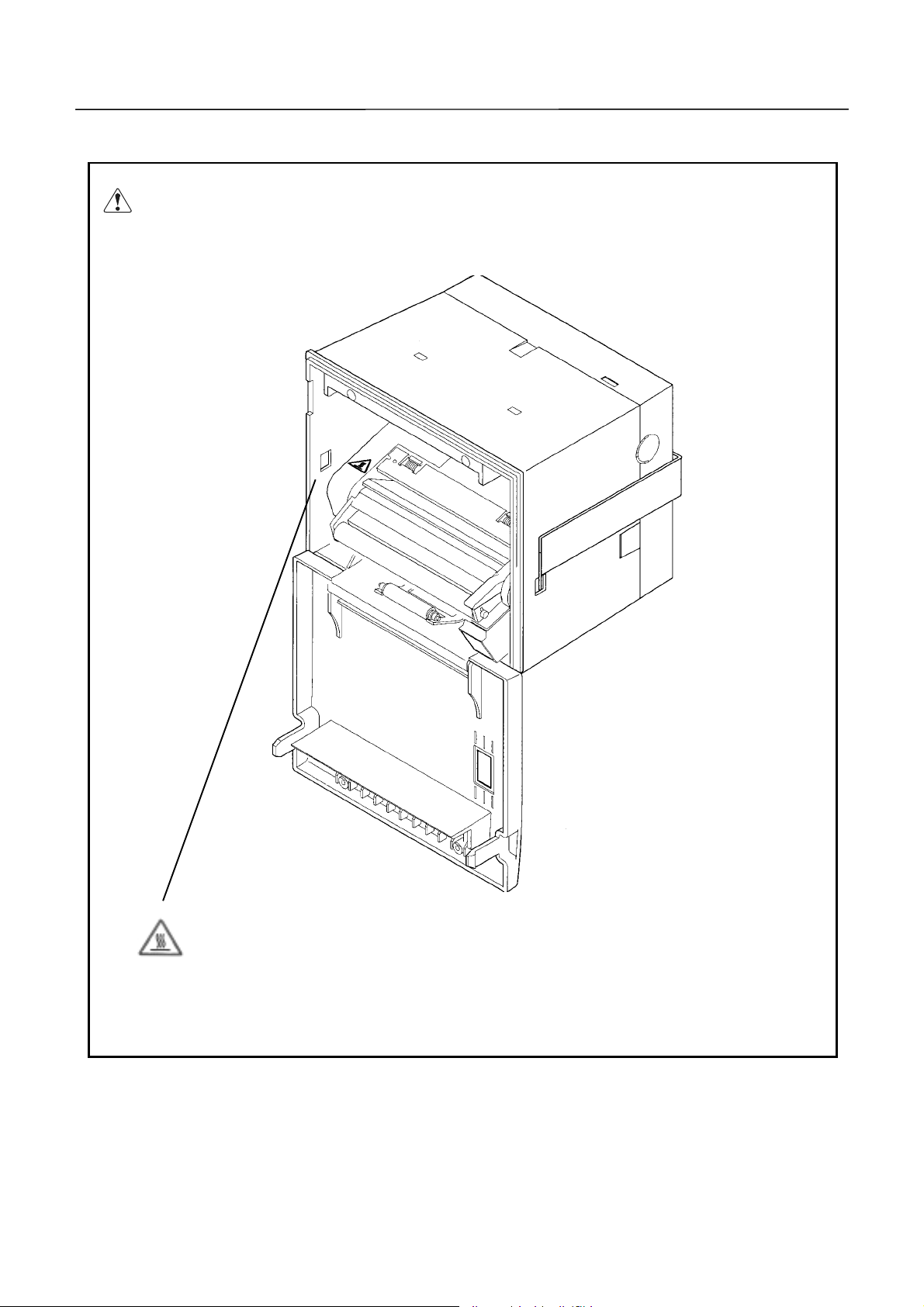
A caution label has been pasted to the position shown in the figure below. Read the
precautions for handling tho roughly, to operate the equipment correctly.
This label alerts you to the danger that
touching the printing head or motor
can cause a burn injury because they
are hot.
12 CITIZEN
Page 13

CBM-292/293 User’s Manual
CCCCOOOONNNNTTTTEEEENNNNTTTTSSSS
1. OUTLINE ..............................................................................................................................................13
1.1 Features ................................................................................................................................................... 13
1.2 Accessories............................................................................................................................................... 13
2. BASIC SPECIFICATIONS...................................................................................................................14
2.1 Model Classifications .............................................................................................................................. 14
2.2 Service Power Source.............................................................................................................................. 14
2.3 Basic Specifications................................................................................................................................. 15
2.4 Paper Specifications ................................................................................................................................ 16
2.4.1 Recommanded Paper........................................................................................................................
2.4.2 Printing Position...............................................................................................................................
2.4.3 Printing Head and Cutter Layout...................................................................................................
16
16
16
3. OUTER APPEARANCE AND COMPONENT PARTS......................................................................17
3.1 Outer Appearance and Component Parts............................................................................................... 17
3.2 Description of Component Parts............................................................................................................. 18
4. OPERATION .........................................................................................................................................19
4.1 Mounting onto the Rack.......................................................................................................................... 19
4.2 Connecting the Power and Data Cable.................................................................................................. 20
4.3 Opening/Closing the Front Cover........................................................................................................... 21
4.4 Feeding the Paper.................................................................................................................................... 21
4.5 Auto Loading Function ........................................................................................................................... 21
4.6 Setting the Printing Paper...................................................................................................................... 22
4.7 Remedies for Paper Jam and Cutter Lock............................................................................................. 23
4.8 Self-printing Function.............................................................................................................................23
4.9 PE and Alarms......................................................................................................................................... 24
4.9.1 Paper End (PE).................................................................................................................................
4.9.2 Alarms...............................................................................................................................................
4.10 Power Supply Method and Connection.................................................................................................. 25
24
24
5. DIP SWITCH SETTING.......................................................................................................................26
6. CONNECTORS .....................................................................................................................................27
6.1 Connector's Pin Configurations.............................................................................................................. 27
13 CITIZEN
Page 14

CBM-292/293 User’s Manual
6.2 Precautions .............................................................................................................................................. 28
6.3 Power Connector Specifications.............................................................................................................. 28
7. PARALLEL INTERFACE.....................................................................................................................29
7.1 Specifications........................................................................................................................................... 29
7.2 Input and Output Signals.......................................................................................................................29
7.3 Electrical Characteristics ....................................................................................................................... 29
7.4 Timing Chart ........................................................................................................................................... 30
7.5 Data Receiving Control ........................................................................................................................... 30
7.6 Buffering .................................................................................................................................................. 30
8. SERIAL INTERFACE...........................................................................................................................31
8.1 Specifications........................................................................................................................................... 31
8.2 Input and Output Signals.......................................................................................................................32
8.3 Data Configuration ................................................................................................................................. 33
8.4 Error Detection........................................................................................................................................ 34
8.5 Data Receiving Control ........................................................................................................................... 34
8.6 Buffering .................................................................................................................................................. 34
8.7 Electrical Characteristics ....................................................................................................................... 35
9. MAINTENANCE AND SERVICE........................................................................................................36
10. PRINT CONTROL FUNCTIONS.........................................................................................................37
10.1 Commands List........................................................................................................................................ 37
10.2 Command Details.................................................................................................................................... 38
10.2.1 Description of Items ..........................................................................................................................
10.2.2 Command Details...............................................................................................................................
38
39
11. CHARACTER CODES TABLE.............................................................................................................80
11.1 International............................................................................................................................................ 80
11.2 Domestic................................................................................................................................................... 81
11.3 International Character Codes Table .................................................................................................... 82
APPENDIX 1. BLOCK DIAGRAM..........................................................................................................83
APPENDIX 2. OUTLINE DRAW ING..................................................................................................... .84
14 CITIZEN
Page 15

CBM-292/293 User’s Manual
<<<
<<< GGGGeeeerrrrmmmmaaaan
<<< <<<
4. BETRIEB...............................................................................................................................................93
4.1 Befestigung auf einem Gestell ............................................................................................................... 93
4.2 Nets-und Datenkabelanschluß............................................................................................................... 94
4.3 Öffnen/Schließen der Frontabdeckung .................................................................................................. 95
4.4 Papiervorschub........................................................................................................................................ 95
4.5 Automatischer Papiereinzng .................................................................................................................. 95
4.6 Einlegen des Druckpapiers..................................................................................................................... 96
4.7 Beseitigung von Papierstans.................................................................................................................. 97
4.8 Selbstdruck funktion............................................................................................................................... 97
4.9 PE und Alarm.......................................................................................................................................... 98
n >>
>>>>>>
n n
>>>>
4.9.1 Papierende (PE)................................................................................................................................
4.9.2 Alarm.................................................................................................................................................
4.10 Betriebsstromversorgung und Anschluß..............................................................................................100
5. EINSTELLUNG DER DIP-SCHALTER............................................................................................101
9. WARTUNG UND DIENST.................................................................................................................102
98
98
15 CITIZEN
Page 16

CBM-292/293 User’s Manual
1111....OOOOUUUUTL
TLIIIINNNNEEEE
TLTL
The CBM-292/293 is a rack mountable thermal panel printer. It is widely applicable to various
kinds of data communication terminals, POS terminals, measuring terminals, and others.
This small-size printer is provided with abundant features. It is available for different
applications. Prior to using it, read this manual thoroughly for full understanding and safe
operation.
1111....1111FFFFeeeeaaaattttuuuurrrreeeessss
1. Rack mountab le small-size line the rmal printer.
2. High speed an d low noise.
3. Long-life printing head used and high reliability due to a simple mechani sm .
4. Serial/parallel interf ace selectable by a DIP sw itch.
5. Built-in input buffer.
6. Capable of printing the bar code(with a special comman d).
7. Provided with an auto c utter(CBM-293 only).
8. Capable of registering the external characters(up to 94 of them).
9. Runs on two types of power sources; external power source and accessory AC adapter.
1111....2222AAAAcccccccceeeessssssssoooorrrriiiieeeessss
When unpacki ng t he printer, confirm that the fol lowing parts are included in the package .
Printer body 1 unit
Sample paper roll 1 piece
Power and data cable 1 piece
Fitting 1 piece
Fitting setscrews 2 pieces
Wire clamp 1 piece
AC adapter(30AD or 31AD) 1 piece (AC adapter-specific model only)
Power cable 1 piece (AC adapter-specific model only)
User's manual 1 copy
16 CITIZEN
Page 17

2222....BA
BASSSSIIIIC
BABA
C SSSSPPPPEC
C C
2222....1111MMMMooooddddeeeel
l CCCCllllaaaass
ssiiiiffffiiiiccccaaaattttiiiioooonnnnssss
l l
ssss
CBM-292/293 User’s Manual
ECIIIIFFFFIIIICCCCAAAATTTTIIIIOOOONNNNSSSS
ECEC
iDP-292/293 ¾ 48 F 120 [ - ( ) ]
Model Name
292: Without Auto Cutter
293: With Auto Cutter
Printing Digits
48: 48 colums(Font A)
(Mechanism: LT381 Used)
Auxiliary Function
Added Depending on
Specifications
(Unrequired for Standard
Model)
AC Adaptor Voltage
120: 120V AC
230: 230V AC
DC: 24V DC(
Character Set
F: International
Without AC
Adaptor)
2222....2222SSSSeeeerrrrvvvviiiicccce
Use the accessory AC adapter(30AD or 31AD).
e PPPPoooowwwweeeer
e e
r SSSSoooouuuurrrrcccceeee
r r
17 CITIZEN
Page 18

CBM-292/293 User’s Manual
2222....3333BBBBaaaassssiiiic
c SSSSppppeeeecccciiiiffffiiiiccccaaaattttiiiioooonnnnssss
c c
Item Description
Printing method Line Thermal
Printing speed 62.5 mm/sec. at maximum
Dot density 8 dots/mm (Horizontal and Vertical)
Printing columns Font A: 48 columns, Font B: 64 columns
Character size Font A: 1.25 mm x 3.00 mm (10 x 24 + 2 dots sp ace),
Font B: 0.88 mm x 2.13 mm (7 x 17 + 2 dots space),
Character types Alphenumerals, international characters
Bar code types UPC-A/E, JAN(EAN) 13 columns/8 columns, ITF, CODE 39,
CODE 128, CODAB AR
Line spacing 4.23 mm(1/6 inch), settable by a command
Paper Thermal paper roll : 80 mm x f50 mm(Max)
Interface Parallel( C ENTRONICS ) or serial(RS-232C)
Selectable by a DIP Switch.
Input buffer 3 KB
Paper en d detection Stops printing when the paper runs out.
Auto loading If new paper is set into the paper inlet, it will be fed
automatically.
Auto cutter (CBM-293 only) Cuts the paper automatically by a command. Either full cut or
partial cut is selectable.
International character set Capable of setting the following 10 countries for specific
character codes by a command.
(U.S., French, German, English, Danish 1 and 2, Swedish,
Italian, Spanish, Japanese, Norwegian)
Supply voltage and power
consumption
AC adapter(30AD/31AD)
Operating temperature
Storage temperature -20 ~ 60 °C, 10 ~ 90 % RH (No dew condensation)
Outer dimensions 126 (W) x 109 (H) x 99 (D) mm
Weight CBM-292: Approx. 500g (Ma in body only)
Applicable standards *1 UL, C UL, TUV (GS)
EMI *1 VCCI: Class A applicable , FCC: Class A applicable
Reliabilit y
24V DC +/-7%. Standby: Approx. 0.2A,
Printing: Approx. 1.8A (Ave) / Peak: Approx. 6A
Rated input: 100 ~ 240V AC, 50/ 60 Hz, 120VA
Rated output: 24V DC, 1.8A
5 ~ 40 °C, 35 ~ 85 % RH (No dew condensation)
CBM-293: Approx. 670g (Ma in body only)
Fitting Metals: Approx. 53g
AC adapter: Approx. 430g
Printing head life:
Pulse resistance --- 50,000,000 pulses (Print ratio: 12.5 %),
Wear resistance --- 30km (With specified paper at normal
temperature and humidity)
Auto cutter life: 300,000 cuts (CBM-293)
1: Applicable when the accessory AC ada pter i s us ed.
*
18 CITIZEN
Page 19
CBM-292/293 User’s Manual
2222....4444PPPPaaaappppeeeer
r SSSSppppeeeecccciiiiffffiiiiccccaaaattttiiiioooonnnnssss
r r
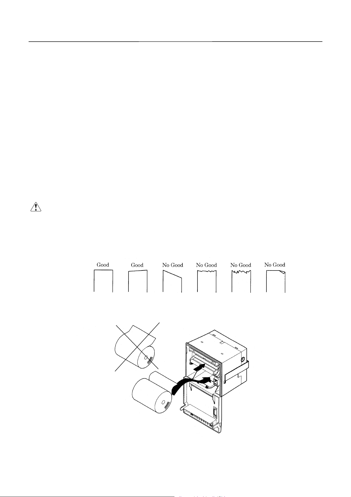
2.4.1 Recommended Paper
Type : Thermal paper
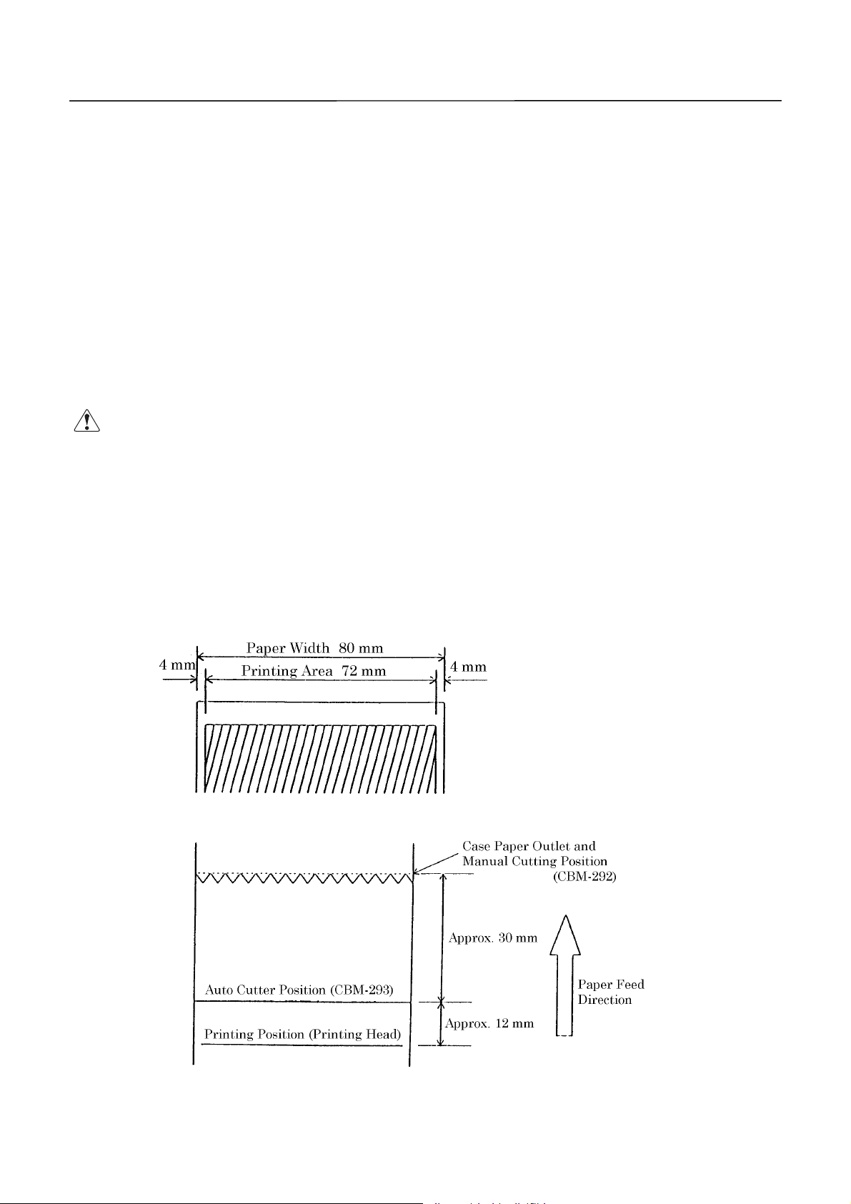
Paper width : 80 plus 0 / minus 1 mm
Paper thickn es s : 65 plus 5 / minus 5mm
Roll diameter :f50 mm(Max)
Printing surface : Outside of the roll(Surface)
Recomme nded paper : TF50KS-E2C by Nippon Sei shi, or its equivalent
Core :f12 mm(Inner diameter), f18 mm(Outer diameter)
CCCCAAAAUUUUTTTTIIIIOOOON
1. User the paper which has not been pasted to the co re.
N ::::
N N
2. Note that if the paper comes into contact with a ch emic al or oil, it ma y di scolor
or lose the printed record.
3. Note that if the paper is rubbed strongly with a nail or hard metal, it may
discolor.
4. Discoloring will start at about 70°C. Watch out fully for effects of the heat,
moisture, light, etc.
2.4.2 Printing Position
2.4.3 Printing Head and Cutter Layout
19 CITIZEN
Page 20
3333.
. OOOOuuuutttteeeer
. .
3333....1
1 OOOOuuuutttteeeer
1 1
r AAAApp
ppeeeeaaaarrrraaaannnncccce
r r
pppp
r AAAAppppppppeeeeaaaarrrraaaannnncccce
r r
e aaaannnnd
d CCCCoooommmmppppoooonnnneeeennnnt
e e
d d
e aaaannnnd
d CCCCoooommmmppppoooonnnneeeennnnt
e e
d d
t PPPPaaaarrrrttttssss
t t
t PPPPaaaarrrrttttssss
t t
CBM-292/293 User’s Manual
20 CITIZEN
Page 21

3333....2
2 DDDDeeeessssccccrrrriiiippppttttiiiioooon
2 2
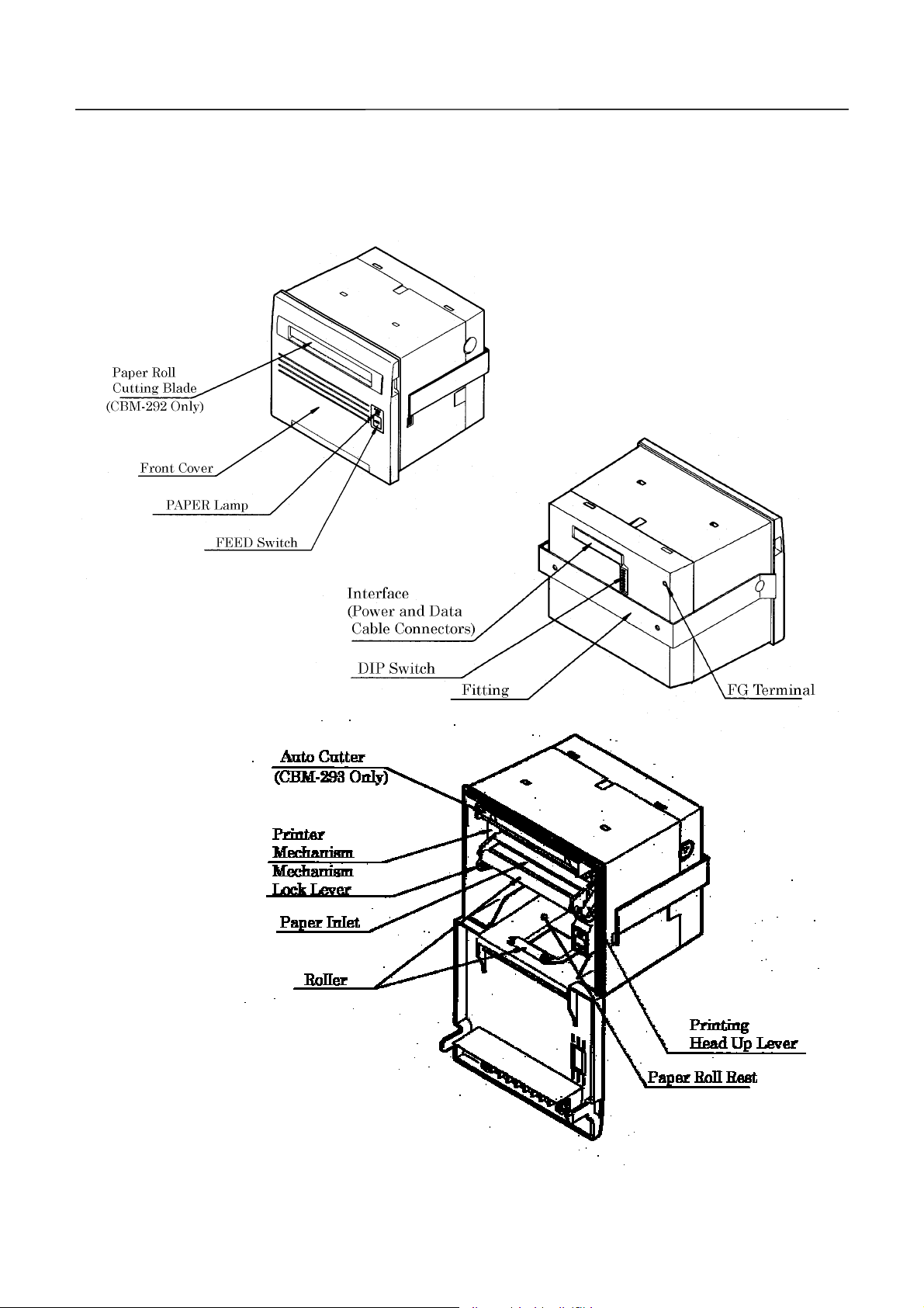
Front cover
·
Open and close the front cover when replacing the paper roll or th e paper is jamming.
PAPER lamp
·
Illuminated when the paper is running out.
FEED switch
·
Press this switch when you want to feed the paper. The paper is fed while the switch is
pressed. If the power is turned on with the switch held down, the printer will perform
self-printing.
Mechanism lock lever
·
Used to lower the mechanism when raising the printing head, when the paper is
jamming or the auto cutter is being locked, or when manually discharging the paper or
n oooof
f CCCCoooommmmppppoooonnnneeeennnnt
n n
f f
t PPPPaaaarrrrttttssss
t t
CBM-292/293 User’s Manual
operating the cutter blade.
Printing head up lever
·
Used to raise the printing head. The printing head has been kept up upon shipment.
Roll paper cutting blade (CBM-292 only)
·
Used to cut the paper.
Fitting metals
·
Used to fix the main body to the rack, etc.
Interface connector
·
Connects the accessory data cable. Provides serial/parallel communications.
DIP switch
·
Used to initially set com municatio n( serial/parallel), printing concentrat ion, etc.
Power co nn ector
·
Connects the accessory AC adapter(power source).
FG terminal
·
Earth terminal for the main body frame. Wire as required.
Auto cutter (CBM-293 only)
·
Automatically cuts the roll paper by a command. Either partial cut or full cut is
selectable.
21 CITIZEN
Page 22
CBM-292/293 User’s Manual
4444....OOOOPPPPER
4444....1111MMMMoooouuuunnnnttttiiiinnnng
CCCCAAAAUUUUTTTTIIIIOOOONNNN::::
ERAAAATTTTIIIIOOOONNNN
ERER
g oooonnnntttto
o tttthhhhe
g g
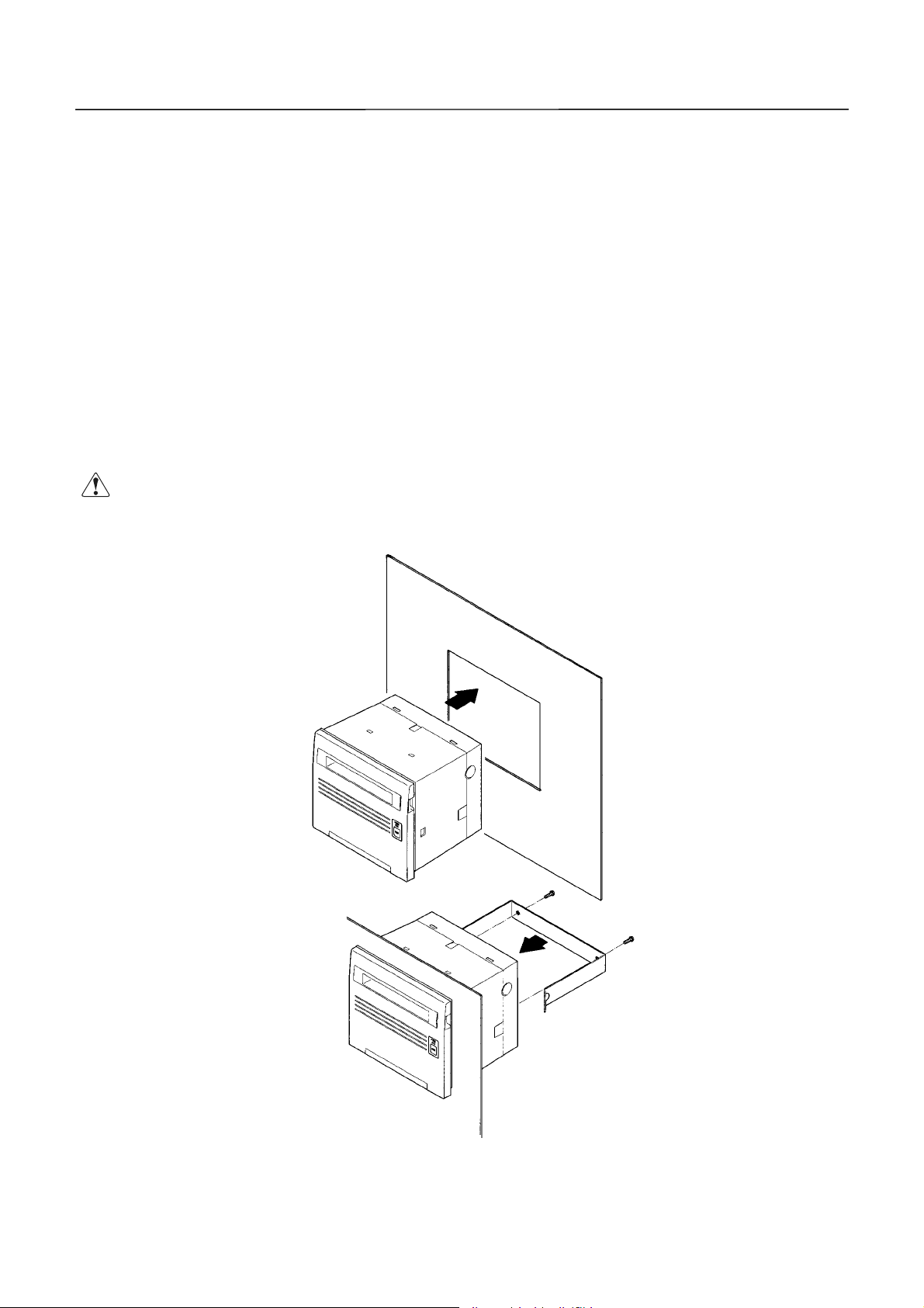
(1) Fit the main body into the specified rac k , etc., as sho wn in the figure below.
(2) Use the accessory fittings to catch the main body from the rear side, and secure it with the
accessory screws.
(3) After mounting, confirm that the front cover will open and close properly.
(4) Tighten the screws to such an extent that the fittings and main body case will not be
deformed. Excessive tightening not only imparts stress to the main body, it can also cause
problems.
(5) The mounting rack sh ould be as thick as 1 ~ 3 mm.
····
e RRRRaaaacccckkkk
o o
e e
Mount the equipment to the rack angled from 0° to 90°. The screws for the
fittings should be within 15mm long.
22 CITIZEN
Page 23
CBM-292/293 User’s Manual
4444....2222CCCCoooonn
CCCCAAAAUUUUTTTTIIIIOOOON
nneeeeccccttttiiiinnnng
nnnn
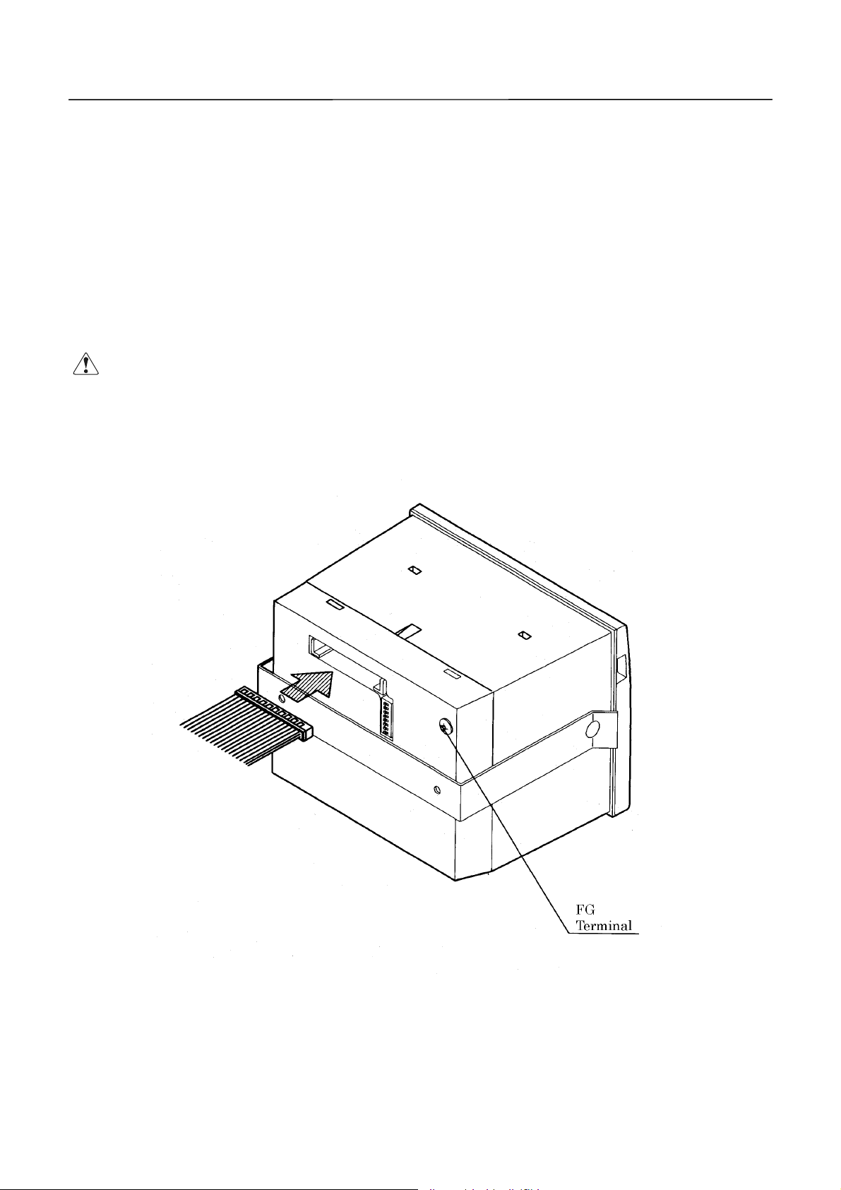
(1) Make sure that the main power source is turned off.
(2) Connect the accessory data cable firmly, making sure of its direction and wiring. A
connecting position is located on the back of the main body.
(3) Plug the accessory AC adapter into a connector until it is locked.
(4) Ground the frame of the main body as require d, t o prevent noise, static electr icit y, and so on.
Secure a grounding conductor firmly to the ground terminal on the back, using a screw.
g tttthhhhe
e PPPPoooowwwweeeer
g g
e e
· Note that the main bo dy is turned on by plugging in an AC cord.
N ::::
N N
Never connect the grounding conductor to a gas pipe.
·
When disconnecting / reconnecting the cable, hold it by the base, as it can snap if
·
held by the cable itself.
r SSSSoooouuuurrrrcccce
r r
e aaaannnnd
e e
d DDDDaaaatttta
d d
a CCCCaaaabbbblllleeee
a a
23 CITIZEN
Page 24
CBM-292/293 User’s Manual
4444....3333OOOOppppeeeennnniiiinnnngggg////CCCClllloooossssiiiinnnng
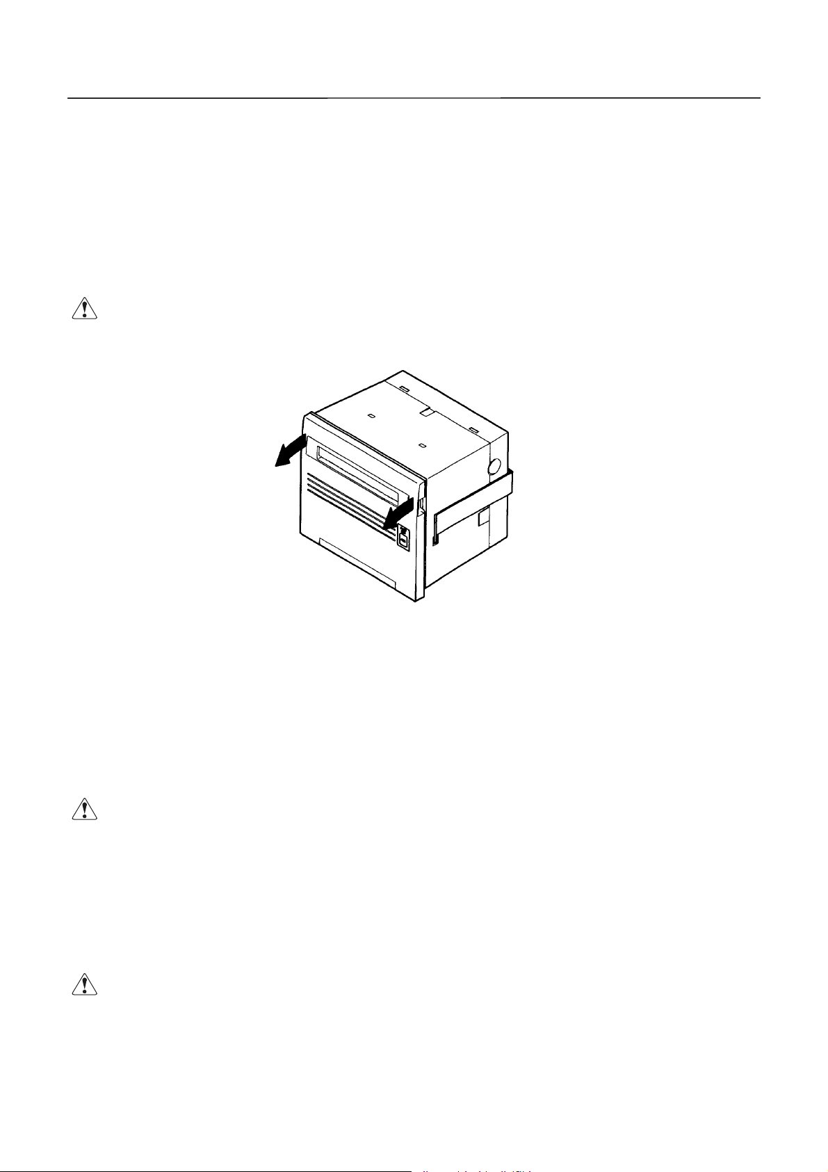
(1) Put your finger in the left and right concavities of the front cover, and pull in the arrow-
indicated direction. The front cover opens about 180 ° downward.
(2) When closing the front cover, hold an d close it firmly. When closing, make sure that the roll
of paper is not slackened. If closed with the paper slack ened, it could jam.
CCCCAAAAUUUUTTTTIIIIOOOONNNN::::
g tttthhhhe
e FFFFrrrroooonnnnt
g g
e e
· When opening the front cover, hold it firmly; because it opens about 180 °, it can
break when opened.
t CCCCoooovvvveeeerrrr
t t
4444....4444FFFFeeeeeeeeddddiiiinnnng
Press the FEED switch on the right panel of the front cover once. The paper is fed by one line.
The paper is also fed while pressing the switch. When you want to feed the paper, do not pull it
by force. Use the FEED switch. Even if the front cover is opened or the me chanism is lowered,
pressing the switch feeds the paper, but it could cause a paper jam .
CCCCAAAAUUUUTTTTIIIIOOOONNNN::::
4444....5555AAAAuuuutttto
The equipment is provided with a function to automatically load a roll of paper into the main
body. If the roll of paper is brought to the paper inlet of the printer mechanism, it will be
automatically fe d by a constant amount.
CCCCAAAAUUUUTTTTIIIIOOOONNNN::::
g tttthhhhe
e PPPPaaaappppeeeerrrr
g g
e e
· Do not press the swit ch with a pointed o bject , as it can cause problems.
o LLLLooooaaaaddddiiiinnnng
o o
g FFFFuuuunnnnccccttttiiiioooonnnn
g g
· Note that pulling the paper can cause a paper jam or insertion miss.
24 CITIZEN
Page 25
CBM-292/293 User’s Manual
4444....6666SSSSeeeett
CCCCAAAAUUUUTTTTIIIIOOOONNNN::::
ttiiiinnnng
g tttthhhhe
tttt
(1) Open the front cover.
(2) Cut the end of the paper almost at a right angle.
(3) Check the paper winding direction, and set the paper in the paper holder inside the case.
(4) Insert the end of th e paper straight into the paper inlet of the printer mechanism. The
paper will be autom at ically inserted.
(5) Remove slack from the paper, and close the front cover.
(6) Press the FEED switch to feed the paper as required.
* The printing head is kept up at the time of shipment. The paper cannot be automatically
* Note that if there are data remaining in the printer buffer, printing will start after auto-
e PPPPrrrriiiinnnnttttiiiinnnng
g g
e e
inserted in the printing-head-up state. Shift the head up lever to the near side, to lower
the printing head.
loading (automati c insertion).
· If the set paper is slanted or not properly fed, move up the printing head, remove
· When replacing the paper, move up the printing hea d and p ull out th e rema in ing
g PPPPaaaappppeeeerrrr
g g
the paper gently, and insert it again.
paper gently.
25 CITIZEN
Page 26

CBM-292/293 User’s Manual
4444....7777RRRReeeemmmmeeeeddddiiiieeees
If the paper jams or the auto cutter is locked, follow the procedure below to eliminate the cause.
For your safety, be sure to turn off the power prior to starting the work.
(1) Open the front cover.
(2) Press the mechanical lock lever inward, to low er t he mechanism .
(3) Eliminating a paper jam. Eliminate all the jamming paper carefully and g ently. When
(4) Unlocking the cutter. Eliminate the paper from the cutter section, and turn on the power.
(5) After eliminating the cause, raise the mechanism back to its home position, return the head
s ffffoooor
r PPPPaaaappppeeeer
s s
r r
pulling out the paper from the printer mechanism, move up the printing head and pull it out
gently.
Cutter unlocking operation will be completed if the cutter blade returns and the initial
operation is performed.
If the cutter blade does not return or an error recurs, turn off the power, and turn the left
inner knob of th e cutter toward the far side, as shown in the figure below. Since the cutter
blade withdraws, eliminate the caught paper gently. Then, turn on the power and confirm
that the initial oper at ion is performed.
up lever, and turn on the power again.
r JJJJaaaam
m aaaannnnd
r r
m m
d CCCCuuuutt
tteeeer
d d
tttt
r LLLLoooocccckkkk
r r
CCCCAAAAUUUUTTTTIIIIOOOON
directly.
4444....8888SSSSeeeellllf-
f-PPPPrrrriiiinnnnttttiiiinnnng
f-f-
The characters used, ROM version, and DIP switch information are printed by turning on the
power with the FEED switch held down or inputting a RESET signal. If the auto-cutter is
attached, the paper will be cut after printing .
· Never work with the printing head or motor immediately after printing, as they
N ::::
N N
are hot and can burn you. If such work is unavoidable, never touch them
Be careful to avoid injury by the metal edges.
·
g FFFFuuuunnnnccccttttiiiioooonnnn
g g
26 CITIZEN
Page 27

CBM-292/293 User’s Manual
4444....9999PPPPE
E aaaannnnd
d AAAAllllaaaarrrrmmmm
E E
d d
4.9.1 Paper End (PE)
The equipment detects if paper is still available. If the paper has run out, it will stop
printing, output BUSY (DTR) and PE, and turn on the PA PER lamp.
If the paper is set, the signals will be canceled and the PAPER lamp will be turned off.
After signal cancellation, the equipment starts printing or waits for data entry. If the
paper has run out, but there are still some data remaining in the buffer, printing will be
resumed after setting new paper.
4.9.2 Alarms
If the auto-cutter is locked, the printing head is up, the printing head temperature is
increasing, or there is a certain failure, such as a paper jam, the equipment will halt
printing, turn off the power for the motor and printing head, and output BUSY (DTR),
ERROR, and FAULT (Parallel only) to the host .
ERROR output can directly connect to an LED.
Error at power-on
·
The following faults are also possible, but a memory error has occurred. Turn off the
power and c ontact your dealer.
When the auto-cutter is locked or the paper is jamming
·
Turn off the power and eliminate the fault. When this is done, the data in the buffer
are erased because the power has been turned off. Do not eliminate the fault with the
power left on. To reset, turn on the power again after eliminating the fault.
When the printing he ad is up
·
Shift the head up lever to the near side. The printing head is lowered, to enable
printing.
When the printing head temperature is increasing
·
If a large amount of data has been printed, such as in continuous printing, etc., the
printing head temperature will increase. If this is the case, printing will stop, to
protect the printing head. While printing is halted, various operations (paper feed,
etc.) are not available. Wait for the printing head temperature to drop. After a while
the printing head temperature will drop, enabling printing. If there are still some
data remaining in the buffer, printing will be resumed.
CCCCAAAAUUUUTTTTIIIIOOOONNNN::::
· Never work with the printing head or motor immediately after printing, as they
directly. Be fully careful of static electricity.
are hot and can burn you. If such work is unavoidable, never touch them
27 CITIZEN
Page 28
CBM-292/293 User’s Manual
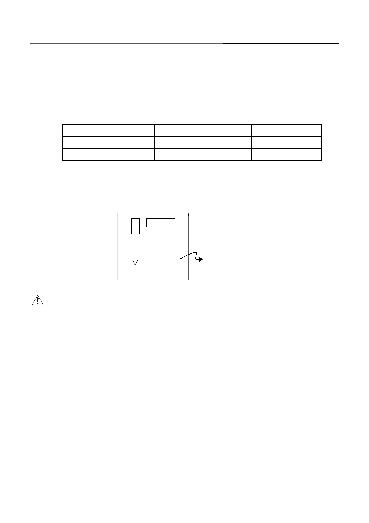
4444....10
10 PPPPoooowwwweeeer
10 10
The power is generally supplied via an AC adapter. If you use an interface cable (accessory
cable) to supply the pow er, connect the cable as follows:
r SSSSuuuupp
pplllly
r r
(1)Connect the accessory cable to the external power source.
y MMMMeeeetttthhhhooood
pppp
y y
Pin No. Signal Name Input/Output Function
d aaaannnnd
d CCCCoooonnnnnnnneeeeccccttttiiiioooonnnn
d d
d d
7, 8, 9, 10, 11, 12 V24
13, 14, 15, 16, 17, 18 GND
(2) Remove the rear cover, to reveal the control board.
Short-circuit the Jumper(J9, Marked by silk print).
OO
J9
CN5
Control Board
Short-circuit
CCCCAAAAUUUUTTTTIIIIOOOONNNN::::
· If the power is supplied via the accessory cable, never connect the AC adapter.
-
-
Power source (+24 V)
Pow er source (GND)
28 CITIZEN
Page 29
CBM-292/293 User’s Manual
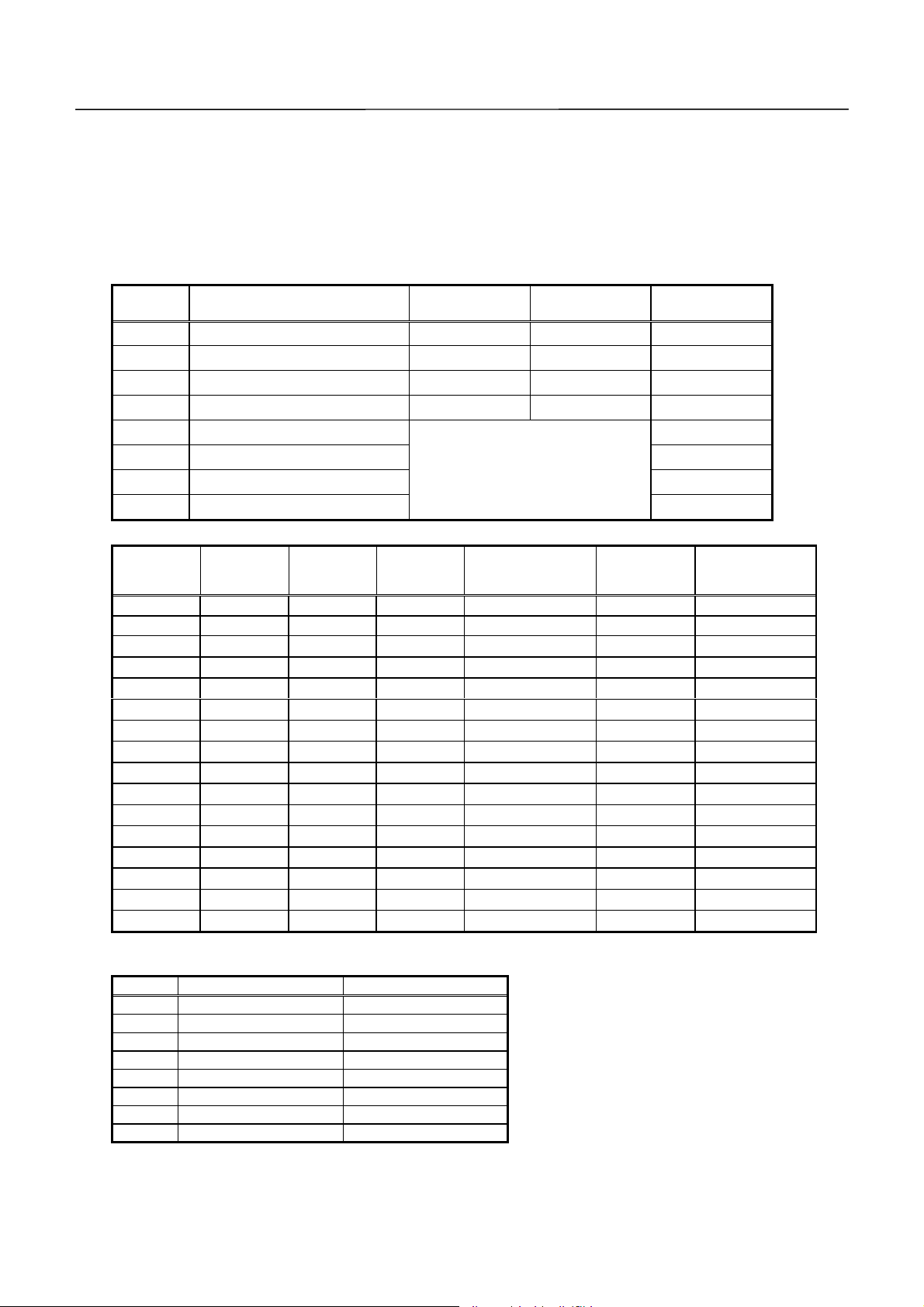
5555....DDDDIIIIP
P SSSSWWWWIIIITTTTCCCCH
P P
H SSSSEEEETTTTTTTTIIIINNNNGGGG
H H
The DIP switch(DS1) is located on the back of the main body. When setting the switch, turn off
the power for the main body. If the setting is changed with the power turned on, it will not
become valid.
DIP Switch
Function ON OFF
Setting upon
Shipment
DS1- 1 Auto cutter Yes No ON
2 CR switching LF operated Ignored OFF
3 Printing density Standard Dark OFF
4 DTR-DSR/XON-XOFF
XON-XOFF DTR-DSR
OFF
5 Interface OFF
6
7
8
²
See the table below
²
²
OFF
OFF
OFF
Interface
DS1-8
OFF OFF OFF OFF Parallel input
OFF OFF OFF ON Serial input None 1,200
OFF OFF ON OFF
OFF OFF ON ON
OFF ON OFF OFF
OFF ON OFF ON
OFF ON ON OFF
OFF ON ON ON
ON OFF OFF OFF
ON OFF OFF ON
ON OFF ON OFF
ON OFF ON ON
ON ON OFF OFF
ON ON OFF ON
ON ON ON OFF
ON ON ON ON
DS1-7 DS1-6 DS1-5
Parity
--
²²
²²
²²
²²
²
Odd 1,200
²²
²²
²²
²²
²
Even 1,200
²²
²²
²²
²²
Baud Rate
(bps)
2,400
4,800
9,600
19,200
2,400
4,800
9,600
19,200
2,400
4,800
9,600
19,200
The main body has been preset with jumpers u pon shipment.
Jumper
Domestic Spec. International Spec.
J1 Open Short
J2 Open Short
J3 Open Short
J4 Short Short
J5 Short Short
J6 Short Short
J7 Short Short
J8 Short Short
* The DS1-4 is inv alid if parallel input is specified.
* The DS1-1 results in an error if set to ON in case of the CBM-292.
29 CITIZEN
1. Domestic Specifications
International characters : Japan
·
Kanji : JIS code
·
Auto loading function
·
Input buffer : 3 KB
·
Serial communication bit length : 8 bits
·
2. International Specifications
International characters : U.S.A.
·
Auto loading function
·
Input buffer : 3 KB
·
· Serial communication bit length : 8 bits
292(OFF)
Page 30

CBM-292/293 User’s Manual
6666....CCCCOOOONNNNNNNNEC
The following lists the wiring of the accessory data cable. Be sure to wire correctly, observing
the connecting direction and pos itio n.
6666....1111CCCCoooonn
1~3, 7~18
ECTTTTOOOORRRRSSSS
ECEC
nneeeeccccttttoooorrrr''''s
nnnn
Pin No. Signal I/O Function
4~6
19
20 ERROR Output ERROR LED output (Directly connectable)
21
22 DTR Output Serial interface DTR
23 TXD Output Serial interface TXD
24 RXD Input Serial interface RXD
25 DSR Input Serial interface DSR
26 STB Input Parallel interface STROB E
27 BUSY Output Parallel interf a ce BUSY
28 ACK Output Parallel interface ACK
29 DATA0 Input Parallel interface DATA 0
30 DATA1 Input Parallel interface DATA 1
31 DATA2 Input Parallel interface DATA 2
32 DATA3 Input Parallel interface DATA 3
33 DATA4 Input Parallel interface DATA 4
34 DATA5 Input Parallel interface DATA 5
35 DATA6 Input Parallel interface DATA 6
36 DATA7 Input Parallel interface DATA 7
37 PE Output Parallel interface PE
38 FAUL T Output Parallel interface FAULT
39 RESET Input Parallel interface RESET
40
s PPPPiiiin
n CCCCoooonnnnffffiiiigggguuuurrrraaaattttiiiioooonnnnssss
s s
n n
--
GND
--
--
--
Unused (Unavailable)
-
Circuit common GND
Unconnectable
Unconnectable
Unconnectable
Connector used: LY20-40P-DT1-P5 (Made by JAE)
Applicable connector: LY10-DC40 (Made by JAE)
* The No. 19 and 21 pins are internally used; do not connect them externally.
CCCCAAAAUUUUTTTTIIIIOOOON
Wr ong w iring damages not onl y t he main body, but the opponent host.
N ::::
····
N N
Never connect the unconnectable pins because it m ay cause the main body t o
·
have a trouble or malfunction.
30 CITIZEN
Page 31

CBM-292/293 User’s Manual
6666....2222PPPPrrrreeeeccccaaaauuuuttttiiiioooonnnnssss
(1) For the ERROR LED output, 330W is included in the circuit of the main body so that a
current value will be approximately 10mA. Use the LED whose forward voltage is
approximately 2V. If the current value exceeds 10m A in oper ation, the control boar d of the
main body may go out of order or be broken.
(2) Connect all grounding conductors.
(3) The serial interface is equipped with a RS-232C driver and receiver. Be sure to use at the
RS-232C lev el.
(4) The RESET pin is pulled u p at 3. 3kW. Do not connect it if not used.
(5) Either serial or paralle l interface is av ailable. If not necessary, do not connect it.
(6) The accessory cable is approx. 300mm. Adjust the length as required. However,
excessively extended wiring may cause malfunctioning due to an effect of noise, etc.
(7) Only the pins for the serial interface should be connected to the 5V or higher power source.
Otherwise, the control board of the main body may be broken.
6666....3333PPPPoooowwwweeeer
r CCCCoooonn
nneeeeccccttttoooor
r r
nnnn
This is a power supply connector from the AC adapter attached to the main body.
Connector's Pin Conf igurations
SHELL FG
r SSSSppppeeeecccciiiiffffiiiiccccaaaattttiiiioooonnnnssss
r r
No. Function
1 +24V
2GND
3N.C
Connector used : TSC7960-53-2010(Made by HOSHIDEN) or its equivalent
Applicable connector : TSC8927-63-1100(Ma de by HOSHIDEN) or its equi valent
TSC8927-53-1100(Made b y HO S H IDEN) or its equivalent
31 CITIZEN
Page 32

CBM-292/293 User’s Manual
7777....PPPPAAAARRRRAAAALL
LLEEEEL
L IIIINNNNTTTTEEEERRRRFFFFAAAACCCCEEEE
LLLL
L L
7777....1111SSSSppppeeeecccciiiiffffiiiiccccaaaattttiiiioooonnnnssss
Data input system : 8-bit parallel sy stem(DATA0 ~ 7)
Control signals : ACK, BUSY, STROBE, FAULT, PE, RESET
7777....2222IIIInnnnppppuuuut
t aaaannnnd
d OOOOuuuuttttppppuuuut
t t
d d
DATA0 ~ 7 : An 8-bit parallel signal.(Positive logic)
·
STROBE : A strobe sig nal to read the 8-bit data. ( Negat ive logic)
·
RESET : A signal to reset the entire control board.(Negative logic)
·
ACK : An 8-bit data request signal.
·
BUSY : A signal to indicate the BUSY status. Input new data when
·
F AULT : A signal turned to "LOW" in case of the alarm status.(Negativ e log ic)
·
PE : A signal to be output when the printing pa per runs out.( Positive logic)
·
t SSSSiiiiggggnnnnaaaallllssss
t t
A pulse signal to be output at the end of the BUSY signal.(Negative
logic)
"LOW."(Positive logic)
7777....3333EEEElllleeeeccccttttrrrriiiiccccaaaal
(1) Input signal levels
(2) Output signal levels
(3) Input/output cond it ions
l CCCChhhhaaaarrrraaaacccctttteeeerrrriiiissssttttiiiiccccssss
l l
"HIGH" level : 0.7Vcc at minimum
"LOW" level : 0.3Vcc at maximum
"HIGH" level : Vcc-0.1V at minimum
"LOW" level : 0.1V at maximum
The STROBE and RESET input signals are all pulled up at 3.3kW. T he others are pulled
up at 50kW.
[Printer Side] [Host Side]
All the output signals are pulled up at 50kW.
32 CITIZEN
Page 33

CBM-292/293 User’s Manual
7777....4444TTTTiiiimmmmiiiinnnng
g CCCChhhhaaaarrrrtttt
g g
The following chart shows the data input and printing timings.
Supply
T1, T2, T3 0.5ms MIN
T4 270ns MAX
T5 2.3ms TYP
T6 500ms MIN (At pow er-on)
7777....5555DDDDaaaatttta
a RRRReeeecccceeeeiiiivvvviiiinnnng
a a
When the BUSY signal is at "LO W," the data can be received from the host, but when at "HIGH,"
it cannot be received.
g CCCCoooonnnnttttrrrroooollll
g g
7777....6666BBBBuuuuffffffffeeeerrrriiiinnnngggg
The main body has a 3KB input buffer. The host side is immediately released because a large
amount of data can be buffered.
33 CITIZEN
Page 34

CBM-292/293 User’s Manual
8888....SSSSEEEERRRRIIIIAAAAL
L IIIINNNNTTTTEEEERRRRFFFFAC
L L
ACEEEE
ACAC
8888....1111SSSSppppeeeecccciiiiffffiiiiccccaaaattttiiiioooonnnnssss
(1) Synchronizing syst em : Asynchronous
(2) Baud rate : 1,200, 2,400, 4,800, 9,600, or 19, 200 bps (User selectable)
(3) Configuration of one word
Start bits : 1 bit
Data bits : 8 bits
Parity bits : Odd, even, or no parity (User selectable)
Stop bits : 1 bit or more
(4) Signal polarity
RS-232C
Mark = Logic "1"(-3 ~ -12 V)
·
Space = Logic "0"(+3 ~ 12 V)
·
(5) Receiv ed data (RXD signal)
RS-232C
Mark = 1
·
Space = 0
·
(6) Reception contro l ( D TR signal)
Mark : Data tran sfer d is abled (BUSY)
·
Space : Data transfer enabled
·
(7) Transmitted data (TXD signal)
Mark = 1
·
Space = 0
·
(8) Tr ansmission control (DSR signal)
Mark : TXD data transmission disabled
·
Space : TXD data transmission enabled
·
(9) Transmission control (TXD s ignal: X-ON/X-OFF contro l)
DC1 code(11H) X-O N : Data reception enabled
·
DC3 code(13H) X-OFF : Data reception disabled
·
34 CITIZEN
Page 35

CBM-292/293 User’s Manual
8888....2222IIIInnnnppppuuuut
t aaaannnnd
t t
(1) TXD
(2) RXD
(3) DTR
(4) DSR
d OOOOuuuuttttppppuuuut
d d
If the input buffer on the printer side has 128 or less remaining bytes while receiving the
data, the DC3(13h) data reception disabled signal will be output. If the input buffer has
256 or more remaining bytes, the DC1(11H) data reception enabled signal will be output to
the host side. At the time of sending the status information, if DTR/DSR control is
selected, the data will be sent after confir ming that DSR is Space. If DTR/DSR is not
selected, the data will be sent, ignoring DSR.
A serial received data signal. If there is a framing error, overrun error, or parity error,
that data will be printed as "?".
When this signal is Space, write a data or command. If written at Mark time(BUSY), an
overrun error will result, ignoring the data. T he data can be written in the input buffer
even during printing. Mark(BUSY) will be generated at power-on, during test printing, at
on-line mode, or at reset time as well.
t SSSSiiiiggggnnnnaaaallllssss
t t
Set to Space when sending the data from the printer to the host in printer status
transmission. When set to Mark, the printer will wait to transmit until the Space status
takes effect, without transmitting the data. Ignored in case of X-ON/X-OFF control.
(5) GND
A signal line at the same level as the GND for t he circuit driving power.
35 CITIZEN
Page 36

CBM-292/293 User’s Manual
8888....3333DDDDaaaatttta
1 2 3
a CCCCoooonnnnffffiiiigggguuuurrrraaaattttiiiioooonnnn
a a
Mark
b0, b1, b2
Space
1 Start Bit
2 Data Bits(+ Parity Bit)
3 Stop Bits (1 or More)
(1) Start bit
....
When a 1/2 bit passes from a fall edge of Mark to Space, the status is read again. If it is
Space, it will be recognized as the start bit. If it is Mark, it will not be recognized as the
start bit. An attempt to detect the start bit will be made again without taking it as an
error.
(2) Data bits + parity bit
The data is sampled at 1 bit worth of time from the 1/2 start bit and the then status is
taken as the data for the relevant bit. The bits are arranged in order of Bit 0, Bit 1 , ...,
Parity Bit, counting from the one closest to the start bit.
(3) Stop bit
The stop bit is the Mark level of 1 bit or more. If Space is detected at stop bit detection
time, a framing error will result.
36 CITIZEN
Page 37

CBM-292/293 User’s Manual
8888....4444EEEErrrrrrrroooor
8888....5555DDDDaaaatttta
r DDDDeeeetttteeeeccccttttiiiioooonnnn
r r
Errors detected include parity error, frami ng error, and overrun error.
(1) Framing error
If the Space status is detected at stop bit detection time, an error will result and that data
will be stored in the in put buffer as "?".
(2) Parity error
If a p arity check has been specified and an error is detected in the parity check, that data
will be stored in the in put buf fer as "?".
(3) Overrun error
If an overrun error is detected, that data will be stored in the input buffer as "?".
a RRRReeeecccceeeeiiiivvvviiiinnnng
a a
If DTR/DSR control has been selected and the DTR signal is at "LOW," the data will be received
from the host. If at "HIGH," it cannot be received. If DTR/DSR control has not been selected,
the data will be received from the host after sending X-ON, but it cannot be sent after sending
X-OFF.
g CCCCoooonnnnttttrrrroooollll
g g
8888....6666BBBBuuuuffffffffeeeerrrriiiinnnngggg
There are TxD and DTR sig nals as control signals f o r d a t a t ransfer to the input buff er.
(1) TXD signal (See 8.2 (1))
(2) DTR signal (See 8.2 (3))
37 CITIZEN
Page 38

CBM-292/293 User’s Manual
8888....7777EEEElllleeeeccccttttrrrriiiiccccaaaal
l CCCChhhhaaaarrrraaaacccctttteeeerrrriiiissssttttiiiiccccssss
l l
(1) RS-232C circuit
Input (RXD, DSR)
[Printer Side] [Host Side]
Equivalent MAX202
Output (DTR, TXD)
RXD
DSR Mark=(-8V):Transmission Disabled
Mark=(-8V): Stop bit
Space=(+8V): Start bit
Space=(+8V):Transmission Enabled
Equivalent MAX202
DTR Mark=(-8V): At Busy
Space=(+8V): At Ready
TXD Mark=(-8V): 1
Space=(+8V): 0
38 CITIZEN
Page 39

CBM-292/293 User’s Manual
9999....MMMMAAAAIIIINNNNTTTTEEEENNNNAAAANNNNCE A
For the information on maintenance and service, please contact our dealer or at the following
address.
North America Other Areas
CBM Ameri ca Corporat ion Japan CBM Corporation
Service Center Information Systems Division
365 Van Ness Way 1-1-7 Okubo Shinjuku-ku,
Suite 510 Tokyo 169-8553 Japan
Torrance, CA 90501, U.S.A
TEL 310-781-1460 TEL 03-3200-6970
FAX 310-781-9157 FAX 03-3200-6297
CE ANNNND
CE ACE A
D SSSSEEEERRRRVVVVIIIICCCCEEEE
D D
39 CITIZEN
Page 40

CBM-292/293 User’s Manual
10
10.... PPPPRRRRIIIINNNNT
1010
10
10....1111 CCCCoooomm
1010
1 HT Horizontal tab 09H
2 LF Printing and paper feed 0AH
3CRPrint 0DH
4 ESC SP Setting the right space amount of the character 1BH 20H n
5 ESC ! Collective specifying printing mode 1BH 21H n
6 ESC % Specifying/canceling download character set 1BH 25Hn
7 ESC & Defining download characters 1BH 26H 5 n m[a p1 p2 ... psxa]m8
9
10 ESC 2 Specifying 1/6-inch line feed rate 1BH 32H
11 ESC 3 Setting line feed rate of minimum pitch 1BH 33H n
12 ESC = Data input control 1BH 3DH n
13 ESC @ Initializing the Printer 1BH 40H
14 ESC D Setting horizontal tab position 1BH 44H [n]k00H
15 ESC E Specifying/canceling highlighting 1BH 45H n
16 ESC G Specifying/canceling double printing 1BH 47H n
17 ESC J Printing and feeding paper n/203 inch 1BH 4AH n
18 ESC R Selecting the international character set 1BH 52H n
19 ESC V
20 ESC a Aligning the characters 1BH 61H n
21 ESC c3 NOP
22 ESC c4 NOP
23 ESC c5 Enabling/disabling the panel switches 1BH 63H 35H n
24 ESC d Printing and feeding the paper by n lines 1BH 64H n
25 ESC I Activating auto cutter (Full cut) 1BH 69H
26 ESC m Activating auto cutter (Partial cut) 1BH 6DH
27 ESC p NOP
28 ESC t Selecting the character code table 1BH 74H n
29 ESC u NOP
30 ESC v Transmitting the printer status (Serial type) 1BH 76H n
31 ESC { Specifying/canceling the inverted characters 1BH 7BH n
32 ESC $ Specifying the absolute positions 1BH 24H n1 n2
33 ESC ¥ Specifying the relative pos itions 1BH 5C n1 n2
34 GS k Printing the bar code 1DH 6BH n [“d”]k00H
35 GS w
36 GS h Selecting the height of the bar code 1DH 68H n
37 GS H Selecting of print position of HRI code 1DH 48H n
38 GS f Selecting the font of HRI code 1DH 66H n
39
40 GS / Printing the download, bit image 1DH 2FH m
41 GS : Starting/ending macro definition 1DH 3AH
42 GS ^ Executing the macro 1DH 5E n1n2 n3
T CCCCOOOONNNNTTTTRRRROOOOL
T T
mmaaaannnnddddssss LLLLiiiisssstttt
mmmm
Control Code Function Code Page
ESC
ESC
GS
*
-
*
L FFFFUN
UNCCCCTTTTIIIIOOOONNNNSSSS
L L
UNUN
Specifying the bit image mode 1BH 2AH mn1n2[d]k
Specifying/canceling underline 1BH 2DH n
Specifying/Canceling 90° -right- turned Characters
Selecting the horizontal size (scale factor) of bar
Defining the download, bit image 1DH2An1n2[d]n1xn2x
1BH 56H n
code 1DH 77H n
39
39
40
40
41
43
44
46
48
48
49
50
51
52
53
54
54
55
56
57
58
58
59
60
61
62
63
64
65
66
70
71
72
73
74
75
77
78
40 CITIZEN
Page 41

CBM-292/293 User’s Manual
10
10....2222 CCCCoooomm
1010
10
10....2222....1
1 DDDDeeeesssscr
1010
1 1
mmaaaannnnd
mmmm
d DDDDeeeettttaaaail
d d
criiiippppttttiiiioooon
crcr
n oooof
f IIIItttteeeemmmmssss
n n
f f
ilssss
ilil
XXXX ALL
[Function] Command F unction
[Code] A sequence of code constituting a command is represented in hexadecimal
number for < >H, binar y number for < >B, and decimal number for < >,
respectively; [ ]k represents a repeat count of k-times.
[Range] Describes an argument value(Setting range) for the command.
[Outline] Describes a command outline.
[Caution] Describes a caution as required.
[Default] Describes an initial value for the command when accompanied by an
argument.
[See Also] Describes the associated commands for use .
[Sample Program] Describes a coding example in the Q-BASIC s ample program.
* This example is only for your reference and differs depending on the
language used, version, and so on. For details, see the manual for the
language used.
41 CITIZEN
Page 42

CBM-292/293 User’s Manual
10
10....2222....2
1010
2 DDDDeeeettttaaaail
2 2
ilssss
ilil
HT
[Function] Horizontal Tab
[Code] <09>H
[Outline] Shifts the printing position to the next horizontal t ab p o sition.
· Ignored when the next horiz ontal tab position has not been set.
[Caution] · The horizontal tab posit ion is set by ESC D.
· Initial setting of the horizontal tab position is each 8 characters in
9th, 17th, 25th, columns.
[See Also] ESC D
[Sample Program]
LPRINT "0123456789012345678901" ;
LPRINT CHR$ (&HA) ;
LPRINT CHR$ (&H9) + "AAA" ;
LPRINT CHR$ (&H9) + "BBB" ;
LPRINT CHR$ (&HA);
LPRINT CHR$ (&H1B) + "D" ;
LPRINT CHR$ (3) + CHR$ (7) + CHR$ (14) + CHR$ (0) ;
LPRINT CHR$ (&H9) + "AAA" ;
LPRINT CHR$ (&H9) + "BBB" ;
LPRINT CHR$ (&H9) + "CCC" + CHR$ (&HA) ;
[Print Results]
LF
[Function] Printing and Paper Feed
[Code] <0A>H
[Outline] Prints data inside the input b uf f er and feeds lines bas ed on the line feed
amount having been set.
· The head of the line becomes t he next print starti ng position.
[See Also] ESC 2, ESC 3
[Sample Program] [Print Results]
LPRINT "AAA" + CHR$ (&HA) ;
LPRINT "BBB" + CHR$ (&HA) ;
LPRINT CHR$ (&HA) ;
LPRINT "CCC" + CHR$ (&HA) ;
42 CITIZEN
Page 43

CBM-292/293 User’s Manual
CR
[Function] Print
[Code] <0D>H
[Outline] 1) When DS 1 -2 is OFF:
This command is ignored.
2) When DS 1- 2 is ON:
With data held inside the internal print buffer, printing and li ne f eed are
performed.
Without data inside the internal print buffer, however, no printing is
performed.
[See Also] LF
[Sample Program] [Print Results]
LPRINT "AAA" + CHR$ (&HD) ;
LPRINT "BBB" + CHR$ (&HD) ;
LPRINT CHR$ (&HD) ;
LPRINT "CCC" + CHR$ (&HD) ;
ESC SP n
[Function] Setting the right space amount of the character
[Code] <1B>H<20>H<n>
[Range] {0 £ n £ 20} Data is described in Hex code.
[Outline] The rightward space amount is set in dot unit (1/203 inch unit). In the
initial value, it is n=0.
[Caution] The rightward space amount in double wide m ode is made double of t he set
volume.
[Default] n = 0
[Sample Program]
LPRINT CHR$ (&H1B) + " " + CHR$ (0) ;
LPRINT "AAAAA" + CHR$ (&HA) ;
LPRINT CHR$ (&H1B) + " " + CHR$ (1) ;
LPRINT "AAAAA" + CHR$ (&HA) ;
LPRINT CHR$ (&H1B) + " " + CHR$ (12) ;
LPRINT "AAAAA" + CHR$ (&HA) ;
[Print Results]
43 CITIZEN
Page 44

CBM-292/293 User’s Manual
ESC ! n
[Function] Collective Specifying Printing M ode
[Code] <1B>H<21>H<n>
[Range] {0 £ n £ FF} Data is described in He x code.
[Outline] Printing mode is assigned. Each n bit indicates the following :
Bit Function
0 Character Font Font A Font B
1 Undefined
2 Undefined
3 High-lighting Canceled Specified
4 Double height Canceled Specified
5 Double width Canceled Specified
6 Undefined
7 Underline Canceled Specified
[Caution] · With double height a nd double width being specifie d simultaneously,
01
Value
double wide and double high characters are consisted.
An underline is attached to the full character width, which, however, is
·
not attached to the part having been skipped by the horizontal tab.
Neither is it attached to 90° -right-turned characters.
· The underline width i s as having been specified by <ESC - >.
(The default setting is 1 dot width. )
· Specification with this com mand is invalid to K anji, except specificat ion
and cancellation of highlighting
· In case that double wide character and normal character exist in s ame
one line, the layout of underline is consistent one.
[Default] n = 0
[See Also] ESC E, ESC
-
44 CITIZEN
Page 45

[Sample Program]
LPRINT CHR$ (&H1B) + " ! " + CHR$ (&H00) + "H" ;
LPRINT CHR$ (&H1B) + " ! " + CHR$ (&H01) + "H";
LPRINT CHR$ (&H1B) + " ! " + CHR$ (&H08) + "H";
LPRINT CHR$ (&H1B) + " ! " + CHR$ (&H10) + "H";
LPRINT CHR$ (&H1B) + " ! " + CHR$ (&H20) + "H";
LPRINT CHR$ (&H1B) + " ! " + CHR$ (&H80) + "H";
LPRINT CHR$ (&H1B) + " ! " + CHR$ (&HB9) + "H";
LPRINT CHR$ (&HA) ;
[Print Results]
CBM-292/293 User’s Manual
45 CITIZEN
Page 46

CBM-292/293 User’s Manual
ESC % n
[Function] Specifying/Canceling Download Character Set
[Code] <1B>H<25>H<n>
[Range] {0 £ n £ FF} data is described in Hex code.
[Outline] Specifying/canceling downloa d characters.
Further, only the lowest bit (n0) is valid for n.
The lowest bit (n0) indicates the following.
n0 Function
0 Canceling download c haracter set
1 Specifying download char acter set
[Caution] Download characters and download bit images can not be defined
simultaneously.
[Default] n = 0
[See Also] ESC &
[Sample Program]
GOSUB SETCHR DATA 6
LPRINT CHR$ (&H1B) + "%" + CHR$ (0) ; DATA &HFF, &H8 0, &H00
LPRINT "@A" + CHR$ (&HA) ; DATA &H80, &H80, &H00
LPRINT CHR$ (&H1B) + "%" + CHR$ (1) ; DATA &H80, &H80, &H00
LPRINT "@A" + CHR$ (&HA) ; DATA &H80, &H80, &H00
END DATA &HFF, &HFF, &HFF
SETCHR : DATA &HFF, &HFF, &HFF
LPRINT CHR$ (&H1B) + "&" ; DATA 12
LPRINT CHR$ (3) + "@" + "A" ; DATA &HFF, &HFF,&HFF
FOR J=1 TO 2 DATA &H80, &H07, &HF9
READ D DATA &HF8, &H06, &H01
LPRINTCHR$ (D) ; DATA &HF8, &H06, &H01
NEXT J DATA &H87, &HFE, &H01
RETURN DATA &H80, &HFF, &HF9
[Print Results]
READ REP DATA &H80, &HFF, &HF9
LPRINT CHR$ (REP) ; DATA &H87, &HFE, &H01
FOR I=1 TO REP*3 DATA &H9F, &H06, &H01
NEXT I DATA &H9F, &H06, &H01
DATA &H80, &H07, &HF9
DATA &HFF, &HFF, &HFF
46 CITIZEN
Page 47

CBM-292/293 User’s Manual
ESC & s n m [ a [ p ] s ´ a] m – n +1
[Function] Defining Download Character
[Code] <1B>H<26>H<s><n><m> [<a><p1><p2> · · <ps´a>]m-n+1
[Range] {s = 03}
{20 (Hex) £ n £ m £ 7E (Hex)}
{0 £ a £ 0C(Hex)} (Font A)
{0 £ a £ 0A(Hex)} (Font B)
[Outline] Defines the font of download characters of al phanumeric characters.
· "s" indicates the number of bytes in vertical direction.
· "n" indicates the start character code and m the end character code. To
define only one character, set n=m.
· Character codes def inable includes 95 ASCII codes in total b et ween
<20>H ~ <7E>H.
· "a" indicates the number of dots in horizontal direction for definition.
· "p" is the data to be defined, which indicate a pattern equal to "a" dot in
horizontal direction from the left end. The rest of the pattern on the
right side is filled with space.
The rest of data to be defined is s x a.
· Download characters thus defined remai n v alid until redefinition,
ESC @ execution, GS * execution, or powe r O FF is practiced.
[Caution] Download characters and download bit images can not be defined
simultaneously.
Running this command clears the definition of the download bit image.
[Default] Same as the internal character set
47 CITIZEN
Page 48

[Example]
CBM-292/293 User’s Manual
Create each data bit by setting "1" for a printed dot and "0" for an
unprinted dot.
[Sample Program] [Print Results]
See Sample Program an d Print Results for ESC % on Page 43.
48 CITIZEN
Page 49

CBM-292/293 User’s Manual
ESC * m n1 n2 [ d ] k
[Function] Specifying the Bit Image Mode
[Code] <1B>H<2A>H<m><n1><n2> [ <d> ] k
[Range] {m= 0, 1, 32, 33 bit image mode (See the table below.)}
{0 £ n1 £ FF(Hex)}
{0 £ n2 £ 03(Hex)}
{0 £ d £ FF(Hex)}
{k = n1 + FF(Hex) ´ n2 (m = 0, 1)
{k = (n1+ FF(Hex) ´ n2) ´ 3} (m = 32, 33)
[Outline] According to the number of dots specified in n1, n2, s pecif y the bit i mage of
mode n.
· The No. of dots printed is divided by 256, whose quotient is taken as n2
and residualas n1.
· The total no. of dots printed in the bit image is equal to n1 + (256 x n2).
· When bit image data hav e been input in excess of dot position of one
line(448 dots) , the excess data are discarded.
· d is bit image data, the bits subject to printing are taken as "1" and those
not as "0".
· The bit image modes spe cif ied by m are shown as f ollows:
m(Hex) Mode
0 8-dots single density 8 67 DPI 101 DPI 288
1 8-dots double density 8 67 DPI 203 DPI 576
20 24-dots single density 24 203 DPI 101 DPI 288
21 24-dots double density 24 203 DPI 203 DPI 576
[Caution] · When the values set in m (bit image mode) are out of the above range,
the data following after n1 is processed as normal printing data.
· After completion of bit image printing, printer ret urns to normal data
Vertical Direction Horizontal Direction
No. of Dots Dot Density Dot Density Max. No. of Dots
processing mode.
49 CITIZEN
Page 50

[Example]
[Sample Program]
LPRINT CHR$ (&H1B) + "*" ;
LPRINT CHR$ (0) + CHR$ (20) + CHR$ (0) ; IMG1 :
GOSUB IMG1 LPRINT CHR$ (&HFF) ;
LPRINT CHR$ (&HA) ; FOR I=1 TO 18
LPRINT CHR$ (&H1B) + "*" ; LPRINT CHR$ (&H85) ;
LPRINT CHR$ (1) + CHR$ (20) + CHR$ (0) ; NEXT I
GOSUB IMG1 LPRINT CHR$ (&HFF) ;
LPRINT CHR$ (&HA) ; RETURN
LPRINT CHR$ (&H1B) + "*" ; IMG2 ;
LPRINT CHR$ (32) + CHR$ (20) + CHR$ (0) ; LPRINT CHR$ (&HFF) ;
GOSUB IMG2 LPRINT CHR$ (&HFF) ;
LPRINT CHR$ (&HA) ; LPRINT CHR$ (&HFF) ;
LPRINT CHR$ (&H1B) + "*" ; FOR I=1 TO 18
LPRINT CHR$ (33) + CHR$ (20) + CHR$ (0) ; LPRINTCHR$ (&H80) ;
GOSUB IMG2 LPRINTCHR$ (&H00) ;
LPRINT CHR& (&HA) ; LPRINTCHR$ (&H05) ;
END NEXT I
[Print Results]
CBM-292/293 User’s Manual
LPRINT CHR$ (&HFF) ;
LPRINT CHR$ (&HFF) ;
LPRINT CHR$ (&HFF) ;
RETURN
50 CITIZEN
Page 51

CBM-292/293 User’s Manual
ESC - n
[Function] Specifying/Canceling Underline
[Code] <1B>H<2D>H<n>
[Range] {0 £ n £ 02} data is described in Hex code.
[Outline] Specifying/canceling an underl ine.
· Types of underlines by n value are shown below:
n (Hex) Type
0 Canceling an underline.
1 Specifying an underline for 1-dot width.
2 Specifying an underline for 2-d ot s width.
[Caution] · An underline is attach ed t o t he full character width. It is, however, not
attached to the part having been skipped by horizontal tab command.
· An underline is not attached to a 90 ° - right-turned characters.
· Specification/cancellation with this com m and is invalid to Kanji.
[See Also] ESC !, FS
-
[Sample Program]
LPRINT CHR$ (&H1B) + "-" + CHR$ (0) ;
LPRINT "AAAAA" ;
LPRINT CHR$ (&H1B) + "-" + CHR$ (1) ;
LPRINT "AAAAA" + CHR$ (&HA) ;
[Print Results]
ESC 2
[Function] Specifying 1/6-inch Line Feed Rate
[Code] <1B>H<32>H
[Outline] The line feed rate per line is specified by 1/6 inch.
[Sample Program] [Print Results]
LPRINT "AAAAA" + CHR$ (&HA) ;
LPRINT CHR$ (&H1B) + "3" + CHR$ (0) ;
LPRINT "AAAAA" + CHR$ (&HA) ;
LPRINT CHR$ (&H1B) + "3" + CHR$ (50) ;
LPRINT "AAAAA" + CHR$ (&HA) ;
LPRINT CHR$ (&H1B) + "2" ;
LPRINT "AAAAA" + CHR$ (&HA) ;
LPRINT "AAAAA" ;
LPRINT CHR$ (&H1B) + "J" + CHR$ (100) ;
LPRINT "AAAAA" + CHR$ (&HA) ;
LPRINT "AAAAA" + CHR$ (&HA) ;
51 CITIZEN
Page 52

CBM-292/293 User’s Manual
ESC 3 n
[Function] Setting Line Feed Rate of Minimum Pitch
[Code] <1B>H<33>H<n>
[Range] {0 £ n £ FF} Data is described in Hex code.
[Outline] The line feed rate per line is specified by n/360 inch.
Since an actual mechanical pitch is 1/ 203 inch, it is internally converted
approximate to the value specified with this command.
[Default] ·The initial value is n = 60 ( 1/6 inch) (18H), being 4.23 mm line feed rate.
[Sample Program] [Print Results]
See Sample Program and Print Result s f or ESC 2 on Page 48.
52 CITIZEN
Page 53

CBM-292/293 User’s Manual
ESC = n
[Function] Data Input Control
[Code] <1B>H<3D>H<n>
[Range] {0 £ n £FF} Data is described in Hex code.
[Outline] Selecting equipment in which data input from the host is ef f ective.
· Each bit of n indicates a s f ollows:
Bit Equipment
01
0 Printer Invalid Valid
1 Not defined
2 Not defined
3 Not defined
4 Not defined
5 Not defined
6 Not defined
7 Not defined
· When the printer ha s not been selected, this printer abandons all the
Value
received data until it is selected by thi s com mand.
[Caution] · Even when the printer has not been selected, it can become BUSY stat e
through printer operation.
· When the printer is deselected, this pri nt er discards all the data until it
is selected with this command.
[Default] · The initial value of n is "1".
[Sample Program]
LPRINT "AAAAA" ;
LPRINT CHR$ (&H1B) + "=" + CHR$ (0) ;
LPRINT "aaaaa" + CHR$ (&HA) ;
LPRINT CHR$ (&H1B) + "=" + CHR$ (1) ;
LPRINT "AAAAA" + CHR$ (&HA) ;
[Print Results]
53 CITIZEN
Page 54

CBM-292/293 User’s Manual
ESC @
[Function] Initializing the Printer
[Code] <1B>H<40>H
[Range] Clears data stored in the print buffer and brings various setting s t o t he
initial state (Default state).
[Caution] · Data inside the internal input buffer are not cl eared.
· Dip switches setting are red once again.
[Sample Program]
LPRINT CHR$ (&H1B) + " ! " + CHR$ (&H30) ;
LPRINT CHR$ (&H1B) + "V" + CHR$ (1) ;
LPRINT "AAA" + CHR$ (&HA) ;
LPRINT CHR$ (&H1B) + "@" ;
LPRINT "AAA" + CHR$ (&HA) ;
[Print Results]
¬ Each setting are in it ialized by reset command.
54 CITIZEN
Page 55

CBM-292/293 User’s Manual
ESC D [ n ] k NUL
[Function] Setting Horizontal Tab Position
[Code] <1B>H<44>H [ <n> ] k<00>H
[Range] {0 £ n £ FFH}
{0 £ k £ 20H} Data is described in Hex code.
[Outline] Specifying a horizontal tab position.
· "n" indicates the no. of columns from the beginning to the horizontal tab
position. At this tim e, n= set position- 1 is to be specified. For ex ample,
to set the position at 9th column, n=8 is to be specified.
· k denotes the number of horizontal tab positio ns y ou want to set.
· The tab position is set at position where it is "character width x n" from
the line beginning. The character width, at this time, inclu des the
rightward space amount. In double wide characters, it is made double
of the ordinary case.
· Tab positions can be specified are maximum 32. Specifying excee di ng
this is ignored.
· <n> k, which denotes a setting position, is input in the increasing order
and ends at <00> H.
· ESC D NUL clears all t he set tab positions. Following clearing,
horizontal tab command is ig nored.
[Caution] When the data, <n> k, is equal t o or smaller than its prec ed ing data, <n>
k-1, it is assumed that tab setting is finished. If this is the case, the next
data onward will be processed as normal data.
When the data, <n> k, exceeds a 1-line print area, set the horizontal tab
position, assuming "Set digit position = Maximum print digits + 1." The
horizontal tab position does not change even if the character width is
altered after setting the horizontal tab position.
[Default] · Initial value is specified for each eight characters(9
of ANK characters.
[See Also] HT
[Sample Program] [Print Results]
See Sample Program and Print Results for HT on Page 39.
55 CITIZEN
th
.17th.25th columns)
Page 56

CBM-292/293 User’s Manual
ESC E n
[Function] Specifying/canceling highlighting
[Code] <1B>H<45>H<n>
[Range] {0 £ n £ FF} Data is described in Hex code.
[Outline] Specifying/canceling the highl ig hting characters.
· "n" is valid only for the lowest bit (n0).
· Control by the lowest bit (n0) is shown as follows:
n0 Ty pe
0 Canceling highlighting.
1 Specifying highlighti ng.
· This is effective to all charact ers.
· Dot configuration of a highlighted char act er includes one extra dot
added at its side.
[Caution] · The print result of Doubl e printing and hig hlight character printing is
completely same.
[See Also] ESC !
[Example]
[Sample Program]
LPRINT CHR$ (&H1B) + "E" + CHR$ (0) ;
LPRINT "AAABBB" + CHR$ (&HA) ;
LPRINT CHR$ (&H1B) + "E" + CHR$ (1) ;
LPRINT "AAABBB" + CHR$ (&HA) ;
[Print Results]
56 CITIZEN
Page 57

CBM-292/293 User’s Manual
ESC G n
[Function] Specifying/canceling Double Pr inting (ESC G n)
[Code] <1B>H<47>H<n>
[Range] {0 £ n £ FF} Data is described in Hex code.
[Outline] Specifying/canceling the doub le p r inting.
· "n" is valid only for the lowest bit (n0).
· Control by n is shown as fol low s.
n0 Type
0 Canceling double printing.
1 Specifying do uble print ing.
This is effective to all characters.
[Caution] · The print result of Doubl e printing and hig hlight character printing is
completely same.
[See Also] ESC E
[Sample Program]
LPRINT CHR$ (&H1B) + "G" + CHR$ (0) ;
LPRINT "AAABBB" + CHR$ (&HA) ;
LPRINT CHR$ (&H1B) + "G" + CHR$ (1) ;
LPRINT "AAABBB" + CHR$ (&HA) ;
[Print Results]
ESC J n
[Function] Printing and feeding paper n/203 inch
[Code] <1B>H<4A>H<n>
[Range] {0 £ n £ FF} Data is described in Hex code.
[Outline] Prints data inside the print buff e r and feeds paper by n/ 360 inch. Since
an actual mechanical pitch is 1/203 inch, it is internally converted
approximate to the value specified with this command.
· Specified volume does not remain.
· The beginning of the line is to be considered as the next pri nt i ng st art
position.
· Initial value is not defined.
[Sample Program] [Print Results]
See Sample Program and Print Result s f o r ESC 2 on Page 48.
57 CITIZEN
Page 58

CBM-292/293 User’s Manual
ESC R n
[Function] Selecting the International Character set
[Code] <1B>H<52>H<n>
[Range] {0 £ n £ 0A) Data is described in Hex code.
[Outline] Depending on the value of n, followi ng character sets are specified.
n(Hex) Character Set
0 U.S.A.
1France
2Germany
3 U.K.
4 Denmark I
5Sweden
6Italy
7Spain
8 Japan
9 Norway
ADenmark II
[Default] The initial value of n are show n below.
· When domestic mode is se lect ed : 8(Japan)
· When international is selected : 0(U.S.A.)
[See Also] Character Code Table (International Character Set)
[Sample Program]
FOR I=0 TO 10
LPRINT CHR$ (&H1B) + "R" + CHR$ (I) ;
LPRINT " #$@[¥]^" ;
LPRINT CHR$ (&H60) + "{|}~”;
LPRINT "n=" + STR$ (I) ;
LPRINT CHR$ (&HA) ;
NEXT I
[Print Results]
58 CITIZEN
Page 59

CBM-292/293 User’s Manual
ESC V n
[Function] Specifying/Canceling 90° -right- turned Characters
[Code] <1B>H<56>H<n>
[Range] {0 £ n £ 1} Data is described in Hex code.
[Outline] Specifying/canceling characters 90° -right- turned character.
· "n" means the followings.
n (Hex) Condition
0
1
Canceling
Specifying
90° -right- turned Characters
90°-right- turned Characters
[Caution] · No underlines are attached to 90° -right- turned characters .
[Default] · The initial value of n is "0".
[Sample Program] [Print Results]
LPRINT CHR$ (&H1B) + "V" + CHR$ (0) ;
LPRINT "AAAAA" ;
LPRINT CHR$ (&H1B) + "V" + CHR$ (1) ;
LPRINT "AAAAA" + CHR$ (&HA) ;
59 CITIZEN
Page 60

CBM-292/293 User’s Manual
ESC a n
[Function] Aligning the characters
[Code] <1B>H<61>H<n>
[Range] {0 £ n £ 2} Data is described in Hex code.
[Outline] All the printed data withi n one line are aligned in t he specified position.
· Depending on n value, positional alig nm ent is carried out as in the t able
below:
n (Hex) Position
0 Left end alignment
1Centering
2 Right end alignment
[Caution] · This is valid only when n is inputted at the beg inning of line.
· The initial value of n is "0".
[Sample Program]
LPRINT CHR$ (&H1B) + "a" + CHR$ (0) ;
LPRINT "AAAAA" + CHR$ (&HA) ;
LPRINT CHR$ (&H1B) + "a" + CHR$ (1) ;
LPRINT "AAAAA" + CHR$ (&HA) ;
LPRINT CHR$ (&H1B) + "a" + CHR$ (2) ;
LPRINT "AAAAA" + CHR$ (&HA) ;
[Print Results]
60 CITIZEN
Page 61

CBM-292/293 User’s Manual
ESC c5 n
[Function] Enabling/Disabling Panel Switches
[Code] <1B>H<63>H<35>H<n>
[Range] {0 £ n £ FF} Data is described in Hex code.
[Outline] Selecting the LF switch valid/invalid.
· "n" is valid only in the low est bit (n0).
· "n" bit means the followings.
n0 Condition
0 LFSW valid.
1 LFSW invalid.
[Caution] When the panel switch is disabled with this com m and, the LF switch is
disabled. Therefore, the paper cannot be fed by operating the LF switch.
[Default] · The initial value of n is "0".
[Sample Program]
LPRINT CHR$ (&H1B) + "c5" + CHR$ (0) ;
LPRINT CHR$ (&H1B) + "c5" + CHR$ (1) ;
..........
..........
When enabling the LF switch
When disabling the LF switch
ESC d n
[Function] Printing and Feeding the paper by n lines
[Code] <1B>H<64>H<n>
[Range] * {0 £ n £ FF} Data is described in Hex code.
[Outline] Prints data inside the buffer and f e eds paper by n lines.
· Specified line does not remain.
· The beginning of the line is to be considered as the next pri nt i ng st art
position.
[Default] · The initial value is not defined.
[Sample Program]
LPRINT "AAAAA"
LPRINT CHR$ (&H1B) + "d" + CHR$ (2) ;
LPRINT "AAAAA" + CHR$ (&HA) ;
[Print Results]
61 CITIZEN
Page 62

CBM-292/293 User’s Manual
ESC i (When Using Auto Paper Cutter)
[Function] Full Cut
[Code] <1B>H<69>H
[Outline] Activating auto cutter unit (Full cut)
[Caution] · This is valid only when n is inputted at the beg inning of line.
· Prior to cutting the pap e r, f eed t he paper from the pri nt ing position to
beyond the paper cutting po sition of the cutter. Otherwise, the
character just after print will remain on this side of the cutter.
[Sample Program]
LPRINT "AAAAA" ;
LPRINT CHR$ (&H1B) + "J" ;
LPRINT CHR$ (150) ;
LPRINT CHR$ (&H1B) + "i" ;
LPRINT "AAAAA" ;
LPRINT CHR$ (&H1B) + "J" ;
LPRINT CHR$ (150) ;
LPRINT CHR$ (&H1B) + "i" ;
[Print Results]
62 CITIZEN
Page 63

CBM-292/293 User’s Manual
ESC m (When Using Auto Paper Cutter)
[Function] Partial Cut
[Code] <1B>H<6D>H
[Outline] Activating auto cutter unit (Partial cut)
[Caution] · This is valid only when n is inputted at the beg inning of line.
· Prior to cutting the pap e r, f eed t he paper from the pri nt ing position to
beyond the paper cutting po sition of the cutter. Otherwise, the
character just after print will remain on this side of the cutter.
[Sample Program]
LPRINT "AAAAA" ;
LPRINT CHR$ (&H1B) + "J" ;
LPRINT CHR$ (150) ;
LPRINT CHR$ (&H1B) + "m" ;
LPRINT "AAAAA" ;
LPRINT CHR$ (&H1B) + "J" ;
LPRINT CHR$ (150) ;
LPRINT CHR$ (&H1B) + "m" ;
[Print Results]
63 CITIZEN
Page 64

CBM-292/293 User’s Manual
ESC t n
[Function] Selecting Character Code Table
[Code] <1B>H<74>H<n>
[Range] {0 £ n £ 1} Data is described in Hex code.
[Outline] Selecting Page n on the character code table:
The character code table is selected depe nding on the value of n.
"n" means the followings.
n (Hex) Condition
0 P age0(IBM Charact er #2)
1 Page1(Domestic Characters)
[Default] The initial value of n are show n below
· When Japan is selected : 1(Domestic characters)
· When non-Japan is selected : 0(IBM characters #2)
[See Also] Character Code Table
[Sample Program]
LPRINT CHR$ (&H1B) + "t" + CHR$ (0) ;
LPRINT " n=0" ;
FOR C=&HB1 TO &HB5
NEXT C
LPRINT CHR$ (&HA) ;
LPRINT CHR$ (&H1B) + "t" + CHR$ (1) ;
LPRINT " n=1" ;
FOR C=&HB1 TO &HB5
NEXT C
LPRINT CHR$ (&HA) ;
[Print Results]
LPRINT CHR$ (C) ;
LPRINT CHR$ (C) ;
64 CITIZEN
Page 65

CBM-292/293 User’s Manual
ESC v (Serial Interface Only)
[Function] Transmitting the printer status(Serial Type)
[Code] <1B>H<76>H
[Outline] Current printer status is transmitted..
[Caution] · Status sent out consists of 1 by t e w hose content is as in the table be low .
· In DTR/DSR control, after receptible state of the host (DSR signal being
in SPACE state) is confirmed, only 1 byte is transmit t ed. In
XON/XOFF control, DSR sig nal state not being confirm ed, only 1 byte
Is transmitted.
· In DTR/DSR control, when the host is in unreceptible state(DSR signal
being in MARK state), it waits until receptible st at e is created.
· In paper end (paper near end) stat us, this command m a y be
Remarks. This command is valid only for s erial interface model.
[Sample Program]
OPEN "COM1:N81NN" AS #1 ;
PRINT #1, CHR$ (&H1B) + "v" ;
A$ = INPUT$ (1, #1) ;
CLOSE #1
unreceptible state due to BUSY state.
Bit Function
0 Not defined
1 Not defined
2 Paper en d With paper Without paper
3 Not defined
4 Not used Fixed to 0
5 Not defined
6 Not defined
7 Not defined
Value
01
-
65 CITIZEN
Page 66

CBM-292/293 User’s Manual
ESC { n
[Function] Specifying/Canceling the Inverted Characters
[Code] <1B>H<7B>H<n>
[Range] {0 £ n £ FF} Data is described in Hex co de.
[Outline] Specifying/canceling inverted characters.
· "n" is valid only for the lowest bit (n0).
· Bit n (n0) means the followings.
n0 Condition
0 Canceling inverted characters.
1 Specifying inverted characters.
[Caution] · Inverted printing means printing the line at 180° turned.
· This is valid only when t his is specified at the beginning of a line.
[Default] · The initial value of n is "0".
[Sample Program]
LPRINT CHR$ (&H1B) + "{" + CHR$ (0) ;
LPRINT "AAAAA" + CHR$ (&HA) ;
LPRINT "BBBBB" + CHR$ (&HA) ;
LPRINT CHR$ (&H1B) + "{" + CHR$ (1) ;
LPRINT "AAAAA" + CHR$ (&HA) ;
LPRINT "BBBBB" + CHR$ (&HA) ;
[Print Results]
66 CITIZEN
Page 67

CBM-292/293 User’s Manual
ESC $ n1 n2
[Function] Specifying the Absolute Positions
[Code] <1B>H<24>H<n1><n2>
[Range] {0 £ n1 £ FF}
{0 £ n2 £ 1} Data is described in Hex code.
[Outline] The printing start position is specified in the number of dots (1/203 inch
unit) from the beginning of line.
· The number of dots is divided by 256, whose quo t ient is taken as n2 an d
the residual as n1.
· Therefore, the printing start position is equal to n1 + n2 x 256 from the
beginning of line..
[Caution] · Specifying beyond the line end is ignored.
[Default] · The initial value is not specified.
[See Also] ESC ¥
[Sample Program]
LPRINT CHR$ (&H1B) + "$" ;
LPRINT CHR$ (0) + CHR$ (0) + "A" ;
LPRINT CHR$ (&H1B) + "$" ;
LPRINT CHR$ (50) + CHR$ (0) + "B" ;
LPRINT CHR$ (&H1B) + "$" ;
LPRINT CHR$ (0) + CHR$ (1) + "C" ;
LPRINT CHR$ (&HA) ;
LPRINT CHR$ (&H1B) + "$" ;
LPRINT CHR$ (100) + CHR$ (0) + "A" ;
LPRINT CHR$ (&H1B) + "¥" ;
LPRINT CHR$ (&HC2) + CHR$ (&HFF) + "B" ;
LPRINT CHR$ (&HA) ;
[Print Results]
67 CITIZEN
Page 68

CBM-292/293 User’s Manual
ESC ¥ n1 n2
[Function] Specifying the Relative Positions
[Code] <1B>H<5C>H<n1>< n2>
[Range] {0 £ n1 £ FF}
{0 £ n2 £ FF} Data is described in Hex code.
[Outline] The printing start position is specified in the number of dots(1/203 inch
unit) from the current position.
· Rightward direction is t aken as plus and leftw ard direction as minus.
· To specify N dot in minus (left) direction, use a complement of N for
assignment.
-N dots = 65536 - N
· The number of dots is divided by 256, whose quo t ient is taken as n2 an d
the residual as n1.
[Caution] · Specifying exceeding the top of line or the end of lin e is ignored.
[Default] · The initial value is not specified.
[See Also] ESC $
[Sample Program] [Print Results]
See Sample Program an d Print Results for ESC $ on Page 64.
68 CITIZEN
Page 69

CBM-292/293 User’s Manual
GS k n [ d ] k NUL
[Function] Printing the Bar Code
[Code] <1D>H<6B>H<n> [ < d> ] k <00>H
[Range] {0 £ n £ 7} Data are described in Hex code.
[Outline] Specifying a type of bar code and printing bar codes.
· The beginning of line is con sidered as the next pr inting start position.
· Depending on the value of n, the following bar code can be selected.
d indicates a character code to be printed and k i nd icates the number of
character to be printed.
n (Hex) Bar Code System Maximum Columns
0 UPC-A --1 UPC-E --2 JAN13 (EAN) --3 JAN 8 (EAN) --4 CODE 39 19
5ITF 35
6 CODABAR (NW-7) 25
7 CODE 128 23
[Caution] · When data being held in t he print buffer, this co m m and is ignored.
· Regardless of the specified feed pitch, this command feeds the paper to
be required to print a bar code.
· If the character code d cannot be printed in the respective b ar co de
system, the bar code so far will be printed, processing t he subsequent
data as normal data.
· When a bar code whose number of characters to be printed is fixed has
been selected, the number of characters k have to be always made equal
to the number of characters to be printed. (The bar code is not printed
when not matching.)
· When the horizontal direction exceeds one line length, the excess part is
not printed.
[Default] · The initial value is not specified.
[Description of Bar Codes] <For print examples, see Page 69.>
UPC-A This bar code, consisting of numerals only, has a fixed length of 12 column; a 11-
columns number entered from the host or application software plus a check
column(12th column) automatically calculated inside the printer. If the 12thcolumn numeral is sent from the host, the e ntire bar code will be print ed as it is.
69 CITIZEN
Page 70

CBM-292/293 User’s Manual
UPC-E This bar code, consisting of numerals only, has a fixed length of 8 column; the
first number system character is "0" stationary. A 12-column numeral entered
from the host or application software is compressed to 8 columns with a check
column and printed. The 12th-column check column is automatically calculated
inside the printer and sent from the host, the entire bar code will be printed,
compressed to 8 columns.
JAN-13(EAN) This bar code, consisting of numerals only, has a fixed length of 13 column; a 12-
column number entered from the host or application software plus a check
column(13th column) automatically calculated inside the printer. If the 13thcolumn numeral is sent from the host, the e ntire bar code will be print ed as it is.
JAN-8(EAN) This bar code, consisting of numerals only, has a fixed length of 8 column; a 7-
column number entered from the host or application software plus a check
column(8th column) automatically calculated inside the printer. If the 8thcolumn numeral is sent from the host, the e ntire bar code will be print ed as it is.
CODE39 This bar code, consisting of uppercase alphabets and numerals, has a variable
length of column. A start/stop code "*" is automatically added by the printer.
Available characters include a space and " $ % * + - · / 0 1 2 3 4 5 6 7 8 9 " and
uppercase alphabets.
ITF This bar code, consisting of numerals only, has a variable length of even column.
If an odd-column code is transferred, no t hing will be printed.
CODABAR (NW-7)
This bar code, consisting of alphanumerals, has a variable length of column.
Available characters include " 0 1 2 3 4 5 6 7 8 9 A B C D $ + - . / : " A start/stop
code is require d; any one of A, B, C, and D is used.
CODE128
This bar code consists of all of 128 ASCII code characters and has a variable
·
length of column. This printer supports the code subsets A, B, and C. By
prefixing a transfer code with any one character of A, B, and C, you can select the
code subset to start from. If not prefixed with A, B, or C, the code subset B will
be selected.
The code subset A is the bar code consisting of standard uppercase alphabets,
·
numerals, symbol s, and special codes.
The code subset B is the bar code consisting of standard uppercase/lowercase
·
alphabets, numer als, symbols, control codes, and special codes.
The code subset C is the bar code consisting of special characters and 100
·
kinds of numbers ranging from 00 to 99.
70 CITIZEN
Page 71

The check column automatically calculated inside the printer is added to the
·
end of the entered column to be printed.
Processing of the special characters
·
The characters above the ASCII code number 96 are considered special
characters. The following lists the converted characters for entering these
characters.
ASCII Code Converted Character Subs et Code A Subset Code B Subset Code C
96 80h FNC 3 FNC 3 -N/A 97 81h FNC 2 FNC 2 -N/A 98 82h SHIFT SHIFT -N/A 99 83h CODE C CODE C -N/A 100 84h CODE B FNC 4 CODE B
101 85h FNC 4 CODE A CODE A
102 86h FNC 1 FNC 1 FNC 1
The following exemplifies a selection of the code subset as a method to utilize the
special characters.
<Selection of Code Subset>
Initial selection: Enter any one character of A, B, and C.
·
Conversion on the way: Enter any one character of 82h through 85h
·
CBM-292/293 User’s Manual
Example) When initially testing with the code subset B, and then, printing the
[Sample Program]
LPRINT CHR$ (&H1D) + "H" + CHR$ (2) ;
LPRINT CHR$ (&H1D) + "k" ;
LPRINT CHR$ (4) ;
LPRINT "123" + CHR$ (0) ;
[Print Results]
bar code, "123," with the code subset A
Input code : B
·
Bar code data : <CODE B>TES T< CO DE A > 12 3
·
TEST <85> 123
71 CITIZEN
Page 72

CBM-292/293 User’s Manual
[Description of Bar Codes]
UPC-A, UPC-E, JAN-13 (EAN), JAN-8 (EAN), CODE39, ITF, CODABAR,
CODE128
Type Print Sample Outline of Symbol Max. column
12-columns fixed-length bar code
UPC-A
UPC-E
JAN-13
JAN-8
CODE39
ITF
consisting of numerals only
8-columns fixed-length bar code
consisting of numerals only.
Abbreviated version of UPC-A
13-columns fixed-length bar code
consisting of numerals only
8-columns fixed-length bar code
consisting of numerals only
Variable-length bar code co nsisting of
alphabets and numerals. The
start/stop code "*" is automatically
added.
Even-columns variable-length bar
code consisting of numerals only 35
-
-
-
-
19
CODABAR
(NW-7)
CODE128
Variable-length bar code consisting of
alphanumerals. Any one of A, B, C,
and D is required as the start/stop
code.
Variable-length bar code consisting of
all 128 ASCII code characters. 23
25
Printing is done de pendin g on bar co de spec ificatio n type, n umber of print col umn,
bar code height, width (Magnification), visible code presence, and bar code data
specification.
72 CITIZEN
Page 73

CBM-292/293 User’s Manual
GS w n
[Function] Selecting the horizontal size(Scale factor) of t he Bar Code
[Code] <1D>H <77>H<n>
[Range] {2 £ n £ 4} Data is described in Hex code.
[Outline] Selecting bar code width.
n denotes the number of dots in fine element width.
[Default] · The initial value of this width is "3".
[Sample Program]
LPRINT CHR$ (&H1D) + "h" + CHR$ (30) ;
LPRINT CHR$ (&H1D) + "w" + CHR$ (2) ;
GOSUB BC
LPRINT CHR$ (&H1D) + "h" + CHR$ (50) ;
LPRINT CHR$ (&H1D) + "w" + CHR$ (3) ;
GOSUB BC
LPRINT CHR$ (&H1D) + "h" + CHR$ (80) ;
LPRINT CHR$ (&H1D) + "w" + CHR$ (4) ;
GOSUB BC
END
BC :
LPRINT CHR$ (&H1D) + "k" ;
LPRINT CHR$ (4) ;
LPRINT "12" + CHR$ (0) ;
RETURN
[Print Results]
73 CITIZEN
Page 74

CBM-292/293 User’s Manual
GS h n
[Function] Selecting the height of the Bar Code
[Code] <1D>H<68>H<n>
[Range] {1 £ n £ FF} Data is described in Hex code.
[Outline] Selecting bar code height.
n denotes the number of dots in the vertical direct ion.
[Default] · The initial value of n is "1 62" .
[Sample Program] [Print Results]
See Sample Program and Print Results for GS w on page 70.
74 CITIZEN
Page 75

CBM-292/293 User’s Manual
GS H n
[Function] Selecting of Printing Position of HRI Code
[Code] <1D>H<48>H<n>
[Range] {0 £ n £ 3} Data is described in Hex code.
[Outline] Selecting printing position of H RI code in printing bar co des.
· "n" means the followings.
n (Hex) Printing Posit ion
0 No printing
1 Above the bar code
2 Below the bar code
3 Both above and below the ba r cod e
The HRI code refers to the bar code-turned characters so that you can
read them.
[Caution] The HRI code is printed in the font selected with GS f.
Specify before the GS k command.
[Defult] · The initial value of n is "0".
[See Also] GS f
[Sample Program] [Print Results]
LPRINT CHR$ (&H1B) + "3" + CHR$ (5) ;
LPRINT CHR$ (&H1D) + "h" + CHR$ (50) ;
LPRINT CHR$ (&H1D) + "H" + CHR$ (0) ;
GOSUB BC
LPRINT CHR$ (&H1D) + "H" + CHR$ (1) ;
GOSUB BC
LPRINT CHR$ (&H1D) + "H" + CHR$ (2) ;
GOSUB BC
LPRINT CHR$ (&H1D) + "H" + CHR$ (3) ;
GOSUB BC
END
BC :
LPRINT CHR$ (&H1D) + "k" ;
LPRINT CHR$ (4) ;
LPRINT "12" + CHR$ (0) ;
LPRINT CHR$ (&HA) ;
RETURN
75 CITIZEN
Page 76

CBM-292/293 User’s Manual
GS f n
[Function] Selecting the font of HRI code
[Code] <1D>H<66>H<n>
[Range] n = 0, 1
[Outline] Selecting the font of HRI code in printing bar code.
The type of font can be printed by select ing n is as follows.
nFont
0Font A
1Font B
The HRI code refers to the bar code-turned characters so that you can
read them.
[Caution] The HRI code is printed at th e position specified with GS h on page 71.
[Default] The initial value of n is “0”.
[See Also] GS H
[Sample Program]
LPRINT CHR$ (&H1D) + "h" + CHR$ (50) ;
LPRINT CHR$ (&H1D) + "H" + CHR$ (2) ;
LPRINT CHR$ (&H1D) + "f" + CHR$ (0) ;
GOSUB BC
LPRINT CHR$ (&H1D) + "f" + CHR$ (1) ;
GOSUB BC
END
BC :
LPRINT CHR$ (&H1D) + "k" ;
LPRINT CHR$ (4) ;
LPRINT "123" + CHR$ (0) ;
LPRINT CHR$ (&HA) ;
RETURN
[Print Results]
76 CITIZEN
Page 77

CBM-292/293 User’s Manual
GS * n1 n2 [ d ] n1 ´ n2 ´ 8
[Function] Defining the Download Bit Image
[Code] <1D>H<2A>H<n1><n2> [ < d > ] n1 ´ n2 ´ 8
[Range] {1 £ n1 £FF}
{1 £ n2 £ 30}
{n1 ´ n2 £ 51F} Data is describe d in Hex code.
[Outline] Defines downloading bit image s of t he number of dots specif ied by n1/n2.
· The numbers of dots are n1 x 8 in horizontal direction and n2 x 8 in vertical
direction.
· d indicates bit image dat a.
· The download bit imag e thus defined remains effective until
redefinition, ESC @ execution, ESC &, or power OFF takes place.
[Caution] · A download character and a download bit image can not be defined
simultaneously.
With this command executed, defined content of a download character is
cleared.
· Relations between the bit im age data and the dot defined are shown
below:
[See Also] GS /
77 CITIZEN
Page 78

CBM-292/293 User’s Manual
[Sample Program] [Print Results]
GOSUB IMG
LPRINT CHR$ (&H1D) + "/" + CHR$ (0) ;
LPRINT CHR$ (&H1D) + "/" + CHR$ (1) ;
LPRINT CHR$ (&H1D) + "/" + CHR$ (2) ;
LPRINT CHR$ (&H1D) + "/" + CHR$ (3) ;
END
IMG :
n 1 = 10 : n 2= 5
LPRINT CHR$ (&H1D) + "*" ;
LPRINT CHR$ (n1) + CHR$ (n2) ;
FOR J=1 TO n1*8
FOR I=1 TO n2
LPRINT CHR$ (J) ;
NEXT I
NEXT J
RETURN
78 CITIZEN
Page 79

CBM-292/293 User’s Manual
GS / m
[Function] Printing the Download, Bit Image
[Code] <1D>H<2F>H<m>
[Range] {0 £ m £ 03} Data is described in Hex code.
[Outline] Prints download bit image in a mo de specified by m.
· Modes can be selected by m are sh ow n below.
m Mode Name Dot Density in
Vertical Direction
0 Normal mode 203 DPI 203 DPI
1 Double wide mode 203 DPI 101 DPI
2 Double high mode 101 DPI 203 DPI
3 Double wide/double high mode 101 DPI 101 DPI
Dot Density in
Horizontal Direction
[Caution] · When data exist inside the print buffer, this command is ignored.
· When a download bit im ag e has not been defined, t his command is
ignored.
· A portion of a download bit image exceeding one line length is not
printed.
· A download character and a download bit image cannot be defined
simultaneously.
[Default] ·The initial value is not specified.
[See Also] GS
[Sample Program] [Print Results]
See Sample Program and Print Results for GS * on Page 74.
*
79 CITIZEN
Page 80

CBM-292/293 User’s Manual
GS :
[Function] Starting / Ending Macro Definiti o n
[Code] <1D>H<3A>H
[Outline] Specifying starting / ending macr o definition.
Means termination when received while def ining a macro.
[Caution] Maximum content available for macro definition is 2048 bytes. A portion
exceeding 2048 bytes is not defined.
· Even with ESC @ (initialization of the pri nter) havi ng been executed,
defined content is not cleared. Therefore, it is possible to include
ESC @ into the content of macro definition.
· Normal printing operat ion is carried out even while in macro definit ion
[Default] · Initially, Macro is not sp ecified.
[See Also] GS ^
[Sample Program] [Print Result s]
LPRINT CHR$ (&H1D) + " : " ;
LPRINT "+ - - - +" + CHR$ (&HA) ;
LPRINT "| |" + CHR$ (&HA) ;
LPRINT "+ - - - +" + CHR$ (&HA) ;
LPRINT CHR$ (&H1D) + " : " ;
LPRINT CHR$ (&H1D) + " ^ " ;
LPRINT CHR$ (2) + CHR$ (10) ;
LPRINT CHR$ (0) ;
80 CITIZEN
Page 81

CBM-292/293 User’s Manual
GS ^ n1 n2 n3
[Function] Executing the Macro
[Code] <1D>H<5E>H<n1><n2><n3>
[Range] {0 £ n1 £ FF}
{0 £ n2 £ FF}
{0 £ 3 £ 1} Data is described in Hex code.
[Outline] Executing contents defined in macro.
· "n1 ~ n3" indicate as follows:
n1 : The number of times of macro execution
n2 : Waiting time on macro execution
Waiting time of n2 x 100 msec is given for every execution.
n3 : Macro execution mode
n3 Mode
0 Continuous exec ut ion
1 Execution by LFSW
Continuous execution: The Macro is executed n1 times continuously at the time
intervals specifie d by n2.
Execution by FEED S: After waiting for lapse of time specified by n2, the
ALAME LED flickers and the LF switch is waited to be
pressed. When it i s pressed, the macro is exec ut ed once.
This action is repeated n1 times.
[Caution] · When this command is received while in mac r o definition, suspen sion of
macro definition is indicated. At this time, the defined content is
cleared.
· No execution takes place when macro is held undefined or n1= 0.
· While in macro execution with n3=1, paper f eed with the LF SW is not
available.
[Default] · Initially, this command is not specified.
[See Also] GS :
[Sample Program] [Print Results]
See Sample Program an d Print Results for GS : on Page 77.
81 CITIZEN
Page 82

11111111.
. CCCCHHHHAAAARRRRAAAACCCCTTTTEEEERRRR CCCCOD
. .
11111111....1111 IIIInnnntttteeeerrrrnnnnaaaattttiiiioooonnnnaaaallll
ODEEEES
ODOD
S TTTTAB
S S
ABLLLLEEEE
ABAB
CBM-292/293 User’s Manual
82 CITIZEN
Page 83

11111111....2
2 DDDDoooommmmeeeessssttttiiiicccc
2 2
CBM-292/293 User’s Manual
83 CITIZEN
Page 84

11111111....3
3 IIIInnnntttteeeerrrrnnnnaaaattttiiiioooonnnnaaaal
3 3
l CCCChhhhaaaarrrraaaacccctttteeeerrrr CCCCoooodddde
l l
e TTTTaaaabbbblllleeee
e e
CBM-292/293 User’s Manual
84 CITIZEN
Page 85

AAAAPP
PPEEEENNNNDDDDIIIIX
PPPP
X 1111.
. BBBBLLLLOOOOCCCCK
X X
. .
K DDDDIIIIAAAAGGGGRRRRAAAAMMMM
K K
CBM-292/293 User’s Manual
85 CITIZEN
Page 86

AAAAPP
PPEEEENNNNDDDDIIIIX
PPPP
X 2222.
. OOOOUUUUTL
X X
. .
TLIIIINNNNE
TLTL
E DDDDRRRRAAAAWWWWIIIINNNNGGGG
E E
CBM-292/293 User’s Manual
Mounting Hole Size
86 CITIZEN
Page 87

<<< German >>>
CBM-292/293 User’s Manual
87 CITIZEN
Page 88

CBM-292/293 User’s Manual
<<<<VVVVOOOORRRRSSSSIIIICCCCHHHHTTTT>>>>
1. Bitte lesen Sie die Bedienungsanleitung vor dem Betrieb des Geräts aufmerksam durch und
bewahren Sie die Anleitung anschließend für späteres Nach schlagen an einem sicheren Platz a uf.
2. Änderungen des Inhalts dieser Anleitung bleib en ohne Vorankündigung v orbehalt e n.
3. Die Vervielfältigung dieser Bedienungsanleitung ohne vorherige Genehmigung verstößt, auch
auszugsweise, gegen das Urheberschutzrecht.
4. Niemals versuchen, in dieser Anleitung nicht erwähnte Geräteteile eigenhändig zu warten,
zerlegen oder zu reparieren.
5. Bitte beachten Sie, daß wir keinerlei Haftung für Schäden übernehmen, die auf unsächgemäße
Bedienung, falsc he Han dh abung oder eine ungeeignete Betrieb sumgebung zurückzuführen sind.
6. Zur Ver meidung von Unfällen und sonstigen Problemen ist das Gerät ausschließlich auf die in
der Bedienungsanleitung beschriebene Weise zu betr eiben.
7. Daten sind grundsätzlich temporär, d.h. sie können nicht permanent gesichert oder über längere
Zeit gespeichert werden. Es sei deshalb darauf hingewiesen, daß wir für finanzielle Schäden oder
Profitrückgänge als Folge von Datenverlust, Unfällen, Reparaturen, Tests usw. keinerlei Haftung
übernehmen.
8. Bitte wenden Sie sich mit Fragen oder Hinweisen auf Fehler oder Auslassungen im Text dieser
Anleitung an unse re G e schäftsstell e.
9. Beachten Sie jedoch, daß wir, ungeachtet des obigen Punkts 8, keinerlei Haftung für negative
Folgeerscheinungen im Zusammenhang mit dem Betrieb dieses Ge räts übernehmen.
VVVVOOOORRRRSSSSIIIICCCCHHHHTTTT
Dieses Gerät ist ein Datentechnologiesystem der Klasse A basierend auf den Normen des
Freiwilligen Selbstüberwachungsrats zur Funkstörung von Datenverarbeitungssystemen
(VVCI). Beim Heimbetrieb des Geräts können Funkstörungen auftreten. Der Benutzer ist
in diesem Fall eventuell dazu angehalten, geeignete Abhilfemaßnahmen zu treffen.
88 CITIZEN
Page 89

CBM-292/293 User’s Manual
ZZZZU
U BBBBEEEEAAAACCCCHHHHTTTTEEEENNNNDDDDE
U U
Zur Ver meidung von Gefahren gegenüber dem Bediener und anderen Personen und
Sachschäden sind die folgenden Vorsichtsmaßregeln unbedingt zu beachten.
Der folgende Text beschreibt das A usma ß der Gefahr en un d potent ielle n Sach sc häden, die dur ch
·
eine Mißachtung der Bedienungshinweise oder durch die unsachgemäße Handhabung des
Geräts entstehen können.
E SSSSIIIICCCCHHHHEEEERRRRHHHHEEEEIIIITTTTSSSSMMMMAAAASS
E E
SSRE
SSSS
REGGGGEEEELLLLNNNN
RERE
WWWWAAAARRRRNNNNUN
UNGGGG
UNUN
VVVVOOOORRRRSSSSIIIICCCCHHHHTTTT
Dieses Symbol ruft den Bediener zu erhöhter Wachsamkeit auf.
Dieses Symbol weist auf wichtige Informationen, wie z.B. Bedienungsschritte oder dergleichen,
hin.
Die Mißachtung dieser V orsichtsmaßregel kann zu Körperverletzungen
mit möglicher Todesfolge führen.
Die Mißachtung dieser V orsichtsmaßregel kann zu Körperverletzungen
oder Sachschäden führen.
89 CITIZEN
Page 90

CBM-292/293 User’s Manual
WARNUNG
Beim Betrieb de s Ge rät s sind di e nac hf o lgende n Vorsichtsma ßrege ln unb eding t zu b eac h te n.
·
Eine Mißachtung dieser Hinweise kann zu Schäden, Funktionsstörungen,
Rauchentw ickl ung un d Bra ndgefahr durc h Über hitze n und z u elektr isc hen S ch lägen f ühren.
Falls Schäden, Störungen, anormale Gerüche oder Geräusche auftreten, das Gerät sofort
ausschalten, das Netzkabel trennen und an einen Fachhändler wenden. Niemals versuchen,
das Gerät eigenhändig zu reparieren, um ernsthafte Gefahren zu vermeiden.
Das Gerät vor starken Stößen und Erschütterungen, wie z.B. Tritte, Stampfen, Schläge,
·
Herunterfallen usw., schützen.
Das Gerät an einem gut belüfteten Platz aufstellen, und darauf achten, die
·
Belüftungsöffnung nicht zu blockieren.
Bei der A ufstell ung des Geräts Plät ze v ermeiden, an denen che misc he R eakt ionen a uftret en,
·
wie z.B. in einem Labor, sowie Plätze mit salz- oder gashaltiger Umgebungsluft.
Das Gerät ausschließlich mit der vorgeschriebenen Betriebsspannung und Netzkapazität
·
betreiben.
Netz- und Datenkabel niemals am Kabel haltend anschließen oder abziehen. Bei Betrieb,
·
Verrücken oder Tragen des Geräts darauf achten, daß die Kabel keiner Gewalteinwirkung
ausgesetzt sind.
Darauf achten, daß keine Fremdköper, wie z.B. Nadeln oder Büroklammern, in das Gerät
·
gelangen.
Niemals mehrere Geräte an die gleiche Steckdose anschließen.
·
Darauf achten, keine Flüssigkeiten auf dem Gerät zu vergießen oder chemis che Substanzen
·
enthaltende Sprays darüber zu versprühen. Bei versehentlichem Naßwerden das Gerät
sofort ausschalten, das Stromanschlußkabel abziehen, das Netzkabel von der Steckdose
trennen usw. und an einen Fachhändler wenden.
Das Gerät niemals eigenhändig zerlegen oder modifizieren. Eine Mißachtung dieser
·
Vorsic ht smaßregel kann zu Br änden und elektr ischen Sc hlägen führen.
Verpackungsbeutel sind vorschriftsgemäß zu entsorgen oder ansonsten von Kindern
·
fernzuhalten. Kleinkinder können durch Überstreifen eines Plastikbeutels ersticken.
90 CITIZEN
Page 91

CBM-292/293 User’s Manual
VVVVOOOORRRRSSSSIIIICCCCHHHHTTTTSSSSMMMMAAAASSSSSSSSRE
Das Gerät nicht an Plätzen abstellen oder betreiben, an denen es Feuer, Feuchtigkeit oder
·
direkter Sonnenbe stra hlung a usgeset zt ist . Ebe nso sind Plät z e in der N ähe v on He izkörpern
und sonstigen Wärmenquellen zu vermeiden, an denen Umgebungstemperatur und
Luftfeuchtigkeit nicht den vorgeschrieben en Betriebsbe dingungen entsprechen, sowie Plätze,
an denen das Gerät Öl, Metallspänen oder Staub ausgesetzt ist. Andernfalls können
Funktionsstörungen sowie Rauch- u nd Brandentwi cklung die Folge sein.
Bei der A ufstell ung des Geräts Plät ze v ermeiden, an denen che misc he R eakt ionen a uftret en,
·
wie z.B. in einem Labor, sowie Plätze mit salz- oder gashaltiger Umgebungsluft. Hierbei
besteht die Gefah r von Bränden und elektrisc hen Schlägen.
Das Gerät auf einer ebenen und stabilen Fläche in einem Winkel zwischen 0º und 90º
·
aufstellen. Der Auf stellplatz sollte gut belüftet und frei von Ersch ütterungen sein.
Für die Aufstellung einen Platz wählen, der den ungehinderten Betrieb des Geräts
·
gewährleistet.
Keine Gegenstän de auf dem Gerät abstellen, da hierdurch Probleme auf t r et en können.
·
Das Gerät mit den mitgelieferten Montageteilen und Schrauben befestigen und die
·
Schrauben korrekt festziehen. Übermäßig festgezogene Schrauben können Probleme und
Schäden verursachen.
Das Gerät nicht in der Nähe eines Radios oder Fernsehers verwenden und nicht zusammen
·
mit einem Radio oder Fernseher an die gleiche Steckdose anschließen. Hierdurch können
Empfangsstörungen auftreten.
Das Gerät ausschließlich mit der vorgeschriebenen Betriebsspannung und Netzkapazität
·
betreiben. Beim Anschließen auf die korrekte Polaritä t achten.
Vergewissern, daß die für den Anschluß des Netzkabels verwendete Steckdose über eine
·
ausreichende Kapazität verfügt.
Das Netzkabel nicht zusammen mit anderen Kabeln verlegen und keine überlangen
·
Verlängerungskabel verwenden, um ein Erwärmen der Netzleitung und eine mögliche
Unterbrechung der Stromversorgung zu vermeiden. Nicht auf Kabel treten, und das Gerät
nicht mit übermäßiger Belastung betreiben.
Erdungskabel ni em als an ein Gasrohr anschließen, da hierbei Explosionsgefahr besteht. Vor
·
dem Anschließen oder Trennen eines Erdungskabels unbedingt zuerst den Netzstecker aus
der Steckdose ziehen.
Darauf achten, vor dem Trennen und Wiederanschließen von Kabeln die Netzversorgung
·
auszuschalten, einschließlich die Kontaktseite.
Steckerkabel sind fest anzuschließen. Durch Anschluß mit umgekehrter Polarität können
·
Innenbauteile oder Paßflächen besch äd igt werden.
Signalübertragungsleitungen sollten nicht zu lang sein und nicht an rauscherzeugende
·
Geräte angeschlossen werden, um durch Rauschstörungen verursachten Datenverlust usw.
zu vermeiden.
Das Gerät an einem Platz in der Nähe einer Steckdose betreiben, wo sich der Netzstecker
·
zum Unterbrech en der Stromversorgung jederzeit schnell und mühelos abziehe n läßt.
Beim Transport oder bei längerer Nichtbenutzung das Gerät mit hochgestelltem Druckkopf
·
transportieren bzw. lagern.
Vor einem Transport die Papierrolle aus dem Gerät herausnehmen.
·
REGGGGEEEELLLLN
RERE
N FFFFÜÜÜÜR
N N
R DDDDIIIIE
R R
E AAAAUUUUFFFFSSSSTTTTEEEELL
E E
LLUUUUNNNNGGGG
LLLL
91 CITIZEN
Page 92

CBM-292/293 User’s Manual
VVVVOOOORRRRSSSSIIIICCCCHHHHTTTTSSSSMMMMAAAASSSSSSSSRE
Zur Vermeidung von Problemen sind bei der Handhabung des Geräts die folgenden
Vorsic ht s m aßregeln zu beachten.
Niemals ohne eingelegte Papierrolle drucken.
·
Darauf achten, daß keine Fremdköper, wie z.B. Nadeln, Büroklammern oder Schrauben, in
·
das Gehäuse gela ngen.
Darauf achten, keine Flüssigkeiten auf dem Gerät zu vergießen oder chemis che Substanzen
·
enthaltende Sprays darüber zu versprühen.
Das Gerät vor starken Stößen un d Erschütterungen bew ahren und nic ht f allen lassen.
·
Niemals mit spitz en Objekten, wie z.B. einem Kugelschre iber, auf das Bedienfeld drücken.
·
Papierblätter niemals zum fortlauf enden Drucken mit K lebestreifen zusam menkleben.
·
Den Papiervorschubknopf niemals mit herabgesenktem Druckkopf drehen oder das Papier
·
gewaltsam von Ha nd herausziehen.
Zur Vermeidung von Verletzungen und Schäde n
Den druckenden Abschnitt des Druckko pfes nicht be rühren.
·
Bei Einschalten keine beweglichen Teile, wie z.B. Schneidklinge und Zahnrad im
·
Druckergehäuse, oder elektrisc he Teile berühren.
Darauf achten, körperliche Verletzungen und die Beschädigung anderer Objekte durch
·
scharfe Kanten zu v ermeiden.
Bei Auftreten jeglicher Störungen während des Betriebs den Drucker sofort ausschalten,
·
und das Netzkabel aus der Steckdo se z iehen.
Die Beseitigung von Betriebsstörungen ist qualifiziertem Fachpersonal zu überlassen.
·
Niemals vers uchen, das Gerät e igenhändig zu zerlegen.
Beim Öffnen/Schließen der Frontabdeckung darauf achten, nicht die Finger oder die Hand
·
einzuklemmen.
REGGGGEEEELLLLN
RERE
N FFFFÜÜÜÜR
N N
R DDDDIIIIE
R R
E HHHHAAAANNNNDDDDHHHHAAAABBBBUN
E E
UNGGGG
UNUN
92 CITIZEN
Page 93

CBM-292/293 User’s Manual
TTTTÄÄÄÄGGGGLLLLIIIICCCCHHHHE
Vor der Wartung zuerst den Drucker ausschalt en.
·
Zum Säubern der Druckwalze ein Wattestäbchen mit Äthylalkohol anfeuchten und Staub
·
und Schm ut z d a m it abwischen.
Schmutz und Staub mit einem trockenen, weichen Tuch vom Druckergehäuse abwischen.
·
Bei starker Verschmutzung einen Lappen in Wasser anfeuchten, auswringen und damit
abwischen. Hierzu niemals flüchtige organische Lösungsmittel, wie z.B. Alkohol, Terpentin,
Trichlorethan, Benzol, Keton oder chemische Staubentfernu ng smittel, verwenden.
Papierstaub mit einer weichen Bürste vom Gehäuse ent f e rnen.
·
VVVVOOOORRRRSSSSIIIICCCCHHHHTTTT::::
Druckkopf und Motor sind sehr heiß und sollten niemals unmittelbar
nach dem Drucken berührt werden.
E WWWWAAAARRRRTTTTUN
E E
UNGGGG
UNUN
93 CITIZEN
Page 94

CBM-292/293 User’s Manual
An der unten gezeigten Stelle (siehe Abbildung) befindet sich ein War naufkleber. Die darauf
angegebenen Vorsichtsmaßregeln zur Handhabung des Geräts sind unbedingt zu befolgen.
Dieser Aufkleber weist darauf hin, daß
ein Berühren von Druckkopf oder
Motor zu Verbrennungen führen kann,
da diese Teile nach dem Drucken heiß
sind.
94 CITIZEN
Page 95

4444....BBBBEEEETTTTRRRRIIIIEEEEBBBB
CBM-292/293 User’s Manual
4444....1111BBBBeeeeffffeeeessssttttiiiiggggun
(1) Das Gerät wie in der untenstehenden Abbildung gezeigt auf einem geeigneten Gestell
(2) Die mitgelieferten Montageteile an der Geräterückseite anbringen und das Gerät mit den
(3) Nach der Befestigung vergewissern, daß sich die Frontabdeckung ungehindert öffnen und
(4) Die Schrauben nicht zu fe st anziehen, damit sich Montageteile und Ge häuse nicht verziehen.
(5) Das Montagegestell sol lte 1 bis 3 mm stark sein.
VVVVOOOORRRRSSSSIIIICCCCHHHHTTTT::::
ung
g aaaauuuuf
unun
befestigen.
beiliegenden Sc hrauben befestigen.
schließen läßt.
Übermäßig festgezogene Schrauben belasten nicht nur das Gehäuse, sondern können auch
andere Probleme verursache n.
f eeeeiiiinnnneeeem
g g
f f
Das Gerät auf einer ebenen und stabilen Fläche in einem Winkel zwischen 0º und
90º aufstellen. Die Sc hrau ben für die Mo ntagete ile sollt en nic ht lä nger als 15 mm
sein.
m GGGGeeeesssstttteeeellllllll
m m
95 CITIZEN
Page 96

CBM-292/293 User’s Manual
4444....2222NNNNeeeettttzzzz-
- uuuunnnnd
d DDDDaaaatttteeeennnnkkkkaaaabbbbeeeellllaaaannnnsssscccchhhhlllluuuußßßß
- -
d d
(1) Vergewissern, daß d ie Netzversorg ung ausgeschaltet ist.
(2) Das mitgelieferte Datenkabel sicher und korrekt ausgerichtet anschließen. Die
Anschlußbuchse für das Kabel befindet sich an der Gehäuserückwand.
(3) Den Stecker des mitgelieferten Akkus ebenfalls fest einschieben.
(4) Falls notwendig das Gerätegehäuse erden, um Rauschen, statische Elektrizität usw. zu
vermeiden. Hierzu eine Erdleitung fest an den Erdungsanschluß an der Rückwand
anschrauben.
VVVVOOOORRRRSSSSIIIICCCCHHHHTTTT::::
Bitte beachten, daß das Gerät durch Anschließen des Netzkabels eingeschaltet
wird. Die Erdleitung niemals an ein Gasrohr anschließen. Das Kabel stets am
Stecker haltend anschließen und abziehen, um Kabelschäden zu vermeiden.
96 CITIZEN
Page 97

CBM-292/293 User’s Manual
4444....3333ÖÖÖÖffffffffnnnneeeennnn////SSSScccchhhhli
(1) Mit den Fingern in die linke und rechte Aussparung der Frontabdeckung eingreifen und die
Abdeckung in Pfeilrichtung ziehen. Die Frontabdeckung öffnet sich um etwa 180º nach
unten.
(2) Beim Schließen die Frontabdeckung halten und fest zuklappen. Hierbei darauf achten, daß
das Rollenpapier gestrafft bleibt, da andernfalls Papierstaus auftreten können.
VVVVOOOORRRRSSSSIIIICCCCHHHHTTTT::::
lieeeeßßßßeeeen
n ddddeeeer
lili
Die Frontabdeckung beim Aufklappen gut festhalten. Da sich die Abdeckung um
etwa 180º öffnet, kann diese a ndernfalls brechen.
r FFFFrrrroooonnnnttttaaaabbbbddddeeeecccckkkkun
n n
r r
ungggg
unun
4444....4444PPPPaaaappppiiiieeeerrrrvvvvoooorrrrsssscccchhhhuuuubbbb
Die FEED-Taste an der rechten Tafel der Frontabdeckung einmal drücken. Das Papier wird
hierdurch um eine Zeile vorgeschoben. Durch anhaltendes Drücken der Taste wird das Papier
fortlaufend vorgeschoben. Das Papier niemals gewaltsam herausziehen, sondern stets durch
Drücken der FEED-Taste vorschieben. Das Papier wird d urc h Drück en der Taste auch bei offener
Frontabdeckung oder herabgesenktem Mechanismus vorgeschoben, jedoch können hierdurch
Papierstaus entstehen.
VVVVOOOORRRRSSSSIIIICCCCHHHHTTTT::::
4444....5555AAAAuuuuttttoooommmmaaaattttiiiisssscccchhhheeeer
Das Gerät verfügt über eine Funktion zum automatischen Einziehen des Papiers. Beim
Einführen des Rollenpapiers in die Papiereinzugöffnung des Druckermechanismus wird eine
bestimmte Menge Papier automatisch eingezogen.
Die Taste nicht mit spitzen Gegenständen drücken, da hierdurch Störungen
auftreten können.
r PPPPaaaappppiiiieeeerrrreeeeiiiinnnnzzzzuuuugggg
r r
97 CITIZEN
Page 98

CBM-292/293 User’s Manual
VVVVOOOORRRRSSSSIIIICCCCHHHHTTTT::::
4444....6666EEEEiiiinnnnlllleeeeggggeeeen
(1) Die Frontabdeckung aufklappen.
(2) Das Papierende in nahezu rechtem W inkel abschneiden.
(3) Die Aufrollrichtung des Papiers bestätigen und die Papierrolle korrekt ausgerichtet ins
(4) Das Papierende gerade in die Papiereinzugöffnung des Druckermechanismus einf ühren. Das
(5) Das Papier st raf f en und die Front abdeckung sc hließen.
(6) Falls notw endig, das Papier durch D rücken der FEED-Taste weiter vorsc hieben.
n ddddeeees
n n
Papierfach e in legen.
Papier wird hierbei automati sch eingezogen.
* Der Versand des Geräts erfolgt mit hochgestelltem Druckkopf. Der automatische
Papiereinzug ist mit dieser Druckkopfsstellung nicht möglich. Zum Vorschieben des Papiers
deshalb zuerst den Kopfhochstellhebel zur nahen Seite hin umstellen, um den Druckkopf zu
senken.
* Bitte beachten, daß der Druckbetrieb nach dem automatischen Papiereinzug selbsttätig
startet, wenn sich noch Daten im D ruckp uf f er befinden.
Ein Ziehen am Papier kann zu Papierstaus oder zu Aussetzern beim
Papiervorsch ub f ühren.
s DDDDrrrruuuucccckkkkppppaaaappppiiiieeeerrrrssss
s s
VVVVOOOORRRRSSSSIIIICCCCHHHHTTTT::::
Druckkopf hochstellen, das Papier vorsichtig entfernen und noch einmal neu
einführen.
·Zum Austausc hen des Papiers den Druckkopf hochstellen un d d as restliche
Papier vorsichtig herausziehen.
·Wenn das P apier schief ausläuft oder nicht korrekt eingezogen wird, den
98 CITIZEN
Page 99

CBM-292/293 User’s Manual
4444....7777BBBBeeeesssseeeeiiiittttiiiiggggun
Wenn sich das Papier staut oder der Schneidmechanismus sperrt, ist die Ursache wie
nachfolgend beschrieben zu bese it igen. Das Gerät zur Sicherheit vorher ausschalten.
(1) Die Frontabdeckung aufklappen.
(2) Den mechanischen Sperrhebel nach innen drücken, u m den Mechanismus herabzusenken.
(3) Den Papierstau durch vorsichtiges Entfernen des gestauten Papiers beseitigen. Zum
(4) Zum Freigeben des Schneidmechanismus zuerst das Papier aus dem Schneidbereich
(5) Nach Beseitigung der Ursache den Mechanismus wieder in die Ausgangsstellung heben, den
ung
g vvvvoooon
unun
Entfernen des Papiers aus dem D ruckermechanismus z uerst den Druckko pf hochstellen und
das Papier anschlie ß e nd vorsichtig herausziehen.
entfernen und anschließend das Gerät einschalten. Nach Rückkehr des Schneidmessers in
die Ausgangsstellung und der Initialisierung des Druckers ist der Schneidmechanismus
wieder funktionersfäh ig.
Wenn das Schneidmesser nicht zurückkehrt oder erneut eine Störung auftritt, das Gerät
ausschalten und, wie in der untenstehenden Abbildung gezeigt, den linken innenliegenden
Knopf des Schneidmechanismus zur entfernten Seite hin drehen. Hierdurch wird das
Schneidmesser zurückgezogen, so daß das gestaute Papier vorsichtig entfernt werden kann.
Anschließend das Gerät wieder ei nschalten und vergewissern, daß der Drucker initialisiert.
Druckkopf-Hochstellhebel zurückstellen und das Ger ät wieder einschalten.
n PPPPaaaappppiiiieeeerrrrssssttttaaaauuuussss
g g
n n
VVVVOOOORRRRSSSSIIIICCCCHHHHTTTT::::
Die obigen Schritte nicht unmittelbar nach dem Drucken ausführen, da
Druckkopf und Motor in diesem Stadium sehr heiß sind und Verbrennungen
verursachen können. Falls sich die Ausführung derartiger Arbeiten nicht
vermeiden läßt, darauf achten, diese Teile nicht direkt zu berühren.
4444....8888SSSSeeeellllbbbbssssttttddddrrrruuuucccckkkkffffuuuunnnnkkkkttttiiiioooonnnn
Durch Drücken der FEED-Taste und gleichzeitiges Einschalten der Netzversorgung oder durch
die Eingabe eines RESET-Signals werden die verwendeten Zeichen, die ROM-Version und die
DIP-Schalter-Information ausgedruckt. S o f ern der automatische Papierschneider angebracht ist,
wird das P apier nach dem Drucken abgesch nit t en.
4444....9999PPPPE
E uuuunnnnd
d AAAAllllaaaarrrrmmmm
E E
d d
4.9.1 Papierende (PE)
Das Gerät erkennt, ob Papier vorhanden ist. Sobald das Papier aufgebraucht ist, stoppt das
Gerät den Druckvorgang, gibt die Signale BUSY (DTR) und PE aus und schaltet das PAPERLämpchen ein.
Beim Nachlegen von Papier werden die Signale gelöscht, und das PAPER-Lämpchen erlischt
99 CITIZEN
Page 100

wieder. Nach dem Löschen der Signale startet das Gerät den Druckbetrieb oder wartet auf die
Eingabe von Daten. Falls bei der Unterb rechung des Druckv organgs noch Daten im Druckpuffer
vorhanden waren, wird der Druckbetrieb bei Nachlegen von Papier fortgesetzt.
4.9.2 Alarm
Wenn der automatische Papierschneider sperrt, der Druckkopf angehoben ist, die
Druckkopftemperatur ansteigt oder bestimmte Störungen, wie z.B. ein Papierstau, auftreten,
stoppt das Gerät den Druckbetrieb, unterbricht die Netzversorgung zu Motor und Druckkopf
und schickt die Signale BUSY (DTR), ERROR und FAULT (nur parallel) an den Hauptrechner.
Der ERROR-Ausgang kann direkt an eine LED angeschlossen werden.
Fehler beim Einschalten
·
Die folgende Störungen sind ebenfa lls m ögli ch, je doc h ist ein S peicherfehler a ufgetret en.
Das Gerät aussch alt en und an einen Fachhän dler wenden.
Wenn der automatische Papierschneider sperrt oder ein Papierstau eingetret en is t
·
CBM-292/293 User’s Manual
Das Gerät ausschalten und die Störungsursache beseitigen. Hierbei werden die Daten
im Druckpuffer durch das Abschalten der Netzversorgung gelöscht. Fehlerursachen
niemals bei eingeschaltetem Gerät beseitigen. Beim Wiedereinschalten nach der
Fehlerbeseitigung wird das Gerät autom a tisch rückgestellt.
Wenn der Druckkopf angehoben ist
·
Den Druckkopf-Hochstellhebel zur nahen Seite hin stellen. Der Druckkopf senkt sich,
und der Druckvorgang kann f ortgeset z t werden.
Wenn die Druckkopftemperatur steigt
·
Nach Ausdrucken einer größeren Datenmenge, wie z.B. beim fortlaufendem
Druckbetrieb usw., steigt die Druckkopftemperatur. In diesem Fall wird der
Druckvorgang zum Schutz des Druckkopfes automatisch unterbrochen. Während einer
solchen Unterbrechung sind bestimmte Funktionen (Papiervorschub usw.) nicht
betriebsfähig. In diesem Fall warten, bis die Druckkopftemperatur gesunken ist. Sobald
der Druckkopf abgekühlt ist, kann wieder gedruckt werden. Falls noch Daten im
Druckpuffer vorhanden waren, wird der Druckvorgang hiernach automatisch
fortgesetzt.
VVVVOOOORRRRSSSSIIIICCCCHHHHTTTT::::
Druckkopf und Motor niemals unmittelbar nach dem Drucken berühren, da
diese Teile sehr heiß sind und Verbrennungen verursachen können. Falls sich
bestimmte Arbeiten in diesem Stadium nicht vermeiden lassen, darauf achten,
diese Teile nicht direkt zu berühren. Vorsicht ist darüber hinaus auch vor
statischer Elektrizität geboten.
100 CITIZEN
 Loading...