

Page 1
Page 2

CBM-253 User’s Manual
Declaration of Conformity
Manufacturer’s Name : Japan CBM Corporation
Manufacturer’s Address: CBM Bldg., 5-68-10, Nakano, Nakano-ku
Tokyo, 164-0001, Japan
Declare the Product
Product Name: Thermal Label Printer
Model Number(s): CBM-253 Series
(CBM-253P, CBM-253R)
(S.No.60400000 ~ )
Conform to the following Standards:
LVD: EN60950 :
EMC: EN55022 :
EN61000-3-2 :
EN50082-1 :
IEC801-2 :
IEC801-3 :
IEC801-4 :
Supplementary Information
“The product complies with the requirements of the Low Voltage Directive 73/23/EEC, 93/68/EEC and
the EMC Direc t ive 89/336/EEC, 91/263/EEC, 92/31/EEC, 93/68EEC”
Place Tokyo, Japan Signature:
Date April.1996
Europe Contact :
Norco Declaration AB
EN61000-3-3 : 1995
1992+A1+A2:1993
1994 Class B
1995
1992
1991 4KV CD, 8KV AD
1984 3V/m, 26MHz-1GHz, AM1KHz 80%
1988 0.5KV Signal Line 1KV AC mains
Full Name : Mikio Moriya
Position : General Manager
R & D Department
Box 7146 S-250 07 Helsingborg, Sweden
Warning
This is a Class A products. In a domestic environment this product may cause radio interference in which case the user
may be required to take adequate measures.
This declaration is applied only for 230V model.
CITIZEN
Page 3

CBM-253 User’s Manual
IMPORTANT SAFETY INSTRUCTIONS
• Read all of these instructions and save them for future reference.
• Follow al l warnings and instructions marked on the product.
• Unplug this product from the wall outlet before cleaning. Do not use liquid or aerosol cleaners.
Use a damp cloth for cleaning.
• Do not use this product near water.
• Do not place this product on an unstable cart, stand or table. The product may fall, causing
serious damage to the product.
• Slots and openings on the back or bottom of the case are provided for ventilation. To ensure
reliable operation of the product and to protect it from overheating, do not block or cover these
openings. The openings should nev er be blocked by placing the product on a bed, sofa, rug of
other simil ar surface. This product should never be placed near or over a radiator or heater. This
product should not be placed in an built-in instal lation unless proper ventilation is provided.
• This product should be operated fr om the type of power source indicated on the marking label. If
you re not sure of the type of power available, consult your dealer or local power company.
• Do not allow anyt hing to rest on t he power cord. Do not place t his product where the cord will be
walked on.
• If an extension c ord i s used with t his product , make sure that the total of the ampere ratings of the
products plugged i nto the extension cord does not exceed the extension cord am pere rating. Also,
make sure that the total of all products plugged into the wall outlet does not exceed 15 amperes.
• Never push objects of any kind into this product through cabinet slots as they may touch
dangerous voltage points or short out parts that could result in a risk of fire or electric shock.
Never spill liquid of any kind on the product.
• Except as expl ained elsewhere in thi s manual, do not attem pt to service thi s product by yourself.
Opening and removing the covers that are marked “Do Not Remove” may expose you to
dangerous voltage points or other risks. Refer all servicing on those compartments to service
personnel.
• Unplug this product from the wall outlet and ref er servici ng to qualified service per sonnel under the
following conditions:
A. When the power cord or plug is damaged or frayed.
B. If liquid has been spilled into the product.
C. If the product has been exposed to rain or water.
D. If the product does not operate normally when the operating instructions are followed. Adjust
only those controls that are covered be the operating instructions since improper adjustment of
other contr ols ma y result in damage and will often require extensive work by a qualified
technician to restore the product to normal operation.
E. If the product has been dropped or the cabinet has been damaged.
F. If the product exhibits a distinct change in performance, indicating a need for service.
• Please keep the poly bag which this equipm ent is packed in away fr om children or throw it away to
prevent chil dr en from putting i t on. Putt ing it on may cause suffocat ion.
CITIZEN
Page 4

CBM-253 User’s Manual
IMPORTANT: This equipment generates, uses, and can radi ate radio fr equency energy and if not
installed and used in accordance with the instruction manual, may cause interference to radio
communications. It has been tested and found to comply with the limits for a Class A computing
device pursuant to Subpart J of Part 15 off FCC Rules, which are designed to provide reasonable
protecti on against such interferenc e when operated in a comm ercial environment. Oper ation of this
equipment in a residential area is likely to cause interference, in which case the user at his own
expense will be required to take whatever measures may be necessary to correct the interference.
CAUTION: Use shielded cable for this equipment.
Sicherheitshinweis
Die Steckdose zum Anschluß dieses Drucker s muß nahe dem Gr ät angebracht und l eicht zugängli ch
sein .
For Uses in Canada
This digital apparatus does not exceed the class A limits for radio noise emissions from digital,
apparatus, as set out in the radio interference regulations of the Canadian department of
communications.
Pour L’utilisateurs Canadiens
Cet appareil numerique ne depasse pas les limit es de caregorie a pour les emissions de brui t radio
emanant d’appareils numeriques, tel que prévu dans les reglements sur l’interference radio du
department Canadien des communications.
CITIZEN
Page 5

CBM-253 User’s Manual
<Cautions>
1. Before using the equipment, be sure to read this User's manual thoroughly.
2. Portions of the contents of this User's manual may be changed without prior notice.
3. The reproduction of part or all of the contents of this User's manual without permission is strictly
forbidden.
4. Absolutely do not carry out maintenance, disassembly, or repair of parts that are not specified in
this User's manual.
5. Note that losses which may be attributed to the customer's wrong operation method or usage
environment will be outside the responsibility of this company.
6. Do not carry out operat ions other than those explained in t his User's manual, since do ing so may
become a cause of accidents or breakdowns.
7. Because data is basically transient, long-period and permanent storage of data will not be possible.
Please note in advance that this company will not be responsible in any way for losses or lost
profits caused through the clearing of data due to breakdowns, repairs, investigations, etc.
8. If any questionable points, mistakes, omitted explanations, etc. are found in the contents of this
document, please notify this compan y.
9. P lease note that notwithstanding the cond itions in above 8, this company will not be responsible
for the consequences of results obtained through operation of this equipment.
CITIZEN
Page 6
CAUTIONS FOR SAFE USE (Be sure to follow these cautions)
f
The cautions that must be followed in order to prevent injury to persons using this equipment
or to other persons, and to protect against damage to property are displayed as shown below.
• The danger of injury or damage resulting from mistaken methods of use and not following
the display ed caution s will be ex plained as follows:
CBM-253 User’s Manual
The WARNING symbol indicates that if the methods of
use is mistaken by not following the explanation given,
WARNING!
there will be a possibility of the occurrence of death or
serious injury.
CAUTION
The CAUTION symbol indicates that if the methods o
use is mistaken by not following the explanation given,
th ere w ill b e a po ssib ili ty o f the occu rre nce o f pr obl ems
or physica l damage.
Th e symb ol represents an illus tration s hown to a ttract rea der ’s a ttentions.
WARNING!
• Do not subject this equipment to excessive force or shocks such as by treading on it, dropping it or
hitting it, since th e se actio ns may resu lt i n d amage causing a danger of fire or electrical shock.
In a situation where the equipment has been damaged, switch off the power, remove the power plug
from the mains outlet, and contact your sales shop.
• Do not in s t a ll th is equipment in unstable locations that are not flat, since there will be a danger of the
equipment falling down or falling over, causing injury.
CITIZEN
Page 7

CBM-253 User’s Manual
WARNING !
• Do not install this equipment in locati ons with poor ventilation, and do not use the equipment in such
a way that the ventilation port is obstructed, since these actions may result in fire or electric shock.
• Do not use this equipment in locations such as la boratories in which chemical reactions take plac e,
or in locations in which the air includes salt or toxic gases, since these actions may result in fire or
electric shock.
• Do not use thi s equi p ment at v olt a ges othe r than t he sp eci fi ed v olt a ge or at fre q uenc i es ot h er than a t
the speci fied freq uencies, si nce the us e other voltages an d frequencies may res ult in br eakdowns ,
creating a danger of fire or electric shock.
In the situation where a breakdown has taken place, switch off the power, remove the power plug
from the mains outlet, and contact your sales shop.
• Do not insert or remo ve the power ca ble s or data cables by pulling on the cables, and do not pull on
or carry the main unit in such a way as to subject the cables to force, since these actions will produce
the risk of o verh eati ng or smokin g , creating a source of fire or electric shock.
• Do not drop or insert foreign objects like paper clips or split pins, etc. into the equipment, since these
actions may cause breakdowns, creating a danger of fire or electric shock.
In the situation where a breakdown has taken place. switch off the power, remove the power plug
from the mains outlet. and contact your sales shop.
• Do not arran g e the power cable so that many plugs are using the same power outlet, since this action
will produce a risk of overheating or smoking, creating a source of fire or electric shock.
CITIZEN
Page 8

CBM-253 User’s Manual
WARNING !
• Do not spill drinks such as tea, coffee or juice, or spray anti-mosquito prepara tions, etc. onto the
equipment, since these actions will result i n breakdowns, fire or electric shock.
If water, etc. has been spilled into the equipment, switch off the power, remove the power plug from
the mains outlet, and contact your sales shop.
• Do not attempt to disassemble or modify this equipment, since these actions will cause fire or
electric shock.
• The plastic bag that contained the equipment should be stored in a location that is out of the reach of
children or should be destroyed, since there is a danger that children may suffocate themselves if
they place the bag over their heads.
• Do not attempt to attach anything other than a solenoid, or to attach a solenoid having a resistance
value o r less than 24Ω to the drawer drive terminal.
The attachmen t of unsp ecifie d equip ment may ca use brea kd own of the equip ment or heat da mage to
the soleno id , resulting in the dang er of fire or electric shock.
• Do not carry out setting of the dip switches while the power plug is still plugged in to the power
outlet, since this action may cause breakdowns or the danger of electric shock.
• Do not remove any screws other than the screws that fix the rear cover, since removing other screws
may cause breakdowns or the danger of electric shock.
CITIZEN
Page 9
CBM-253 User’s Manual
CAUTION
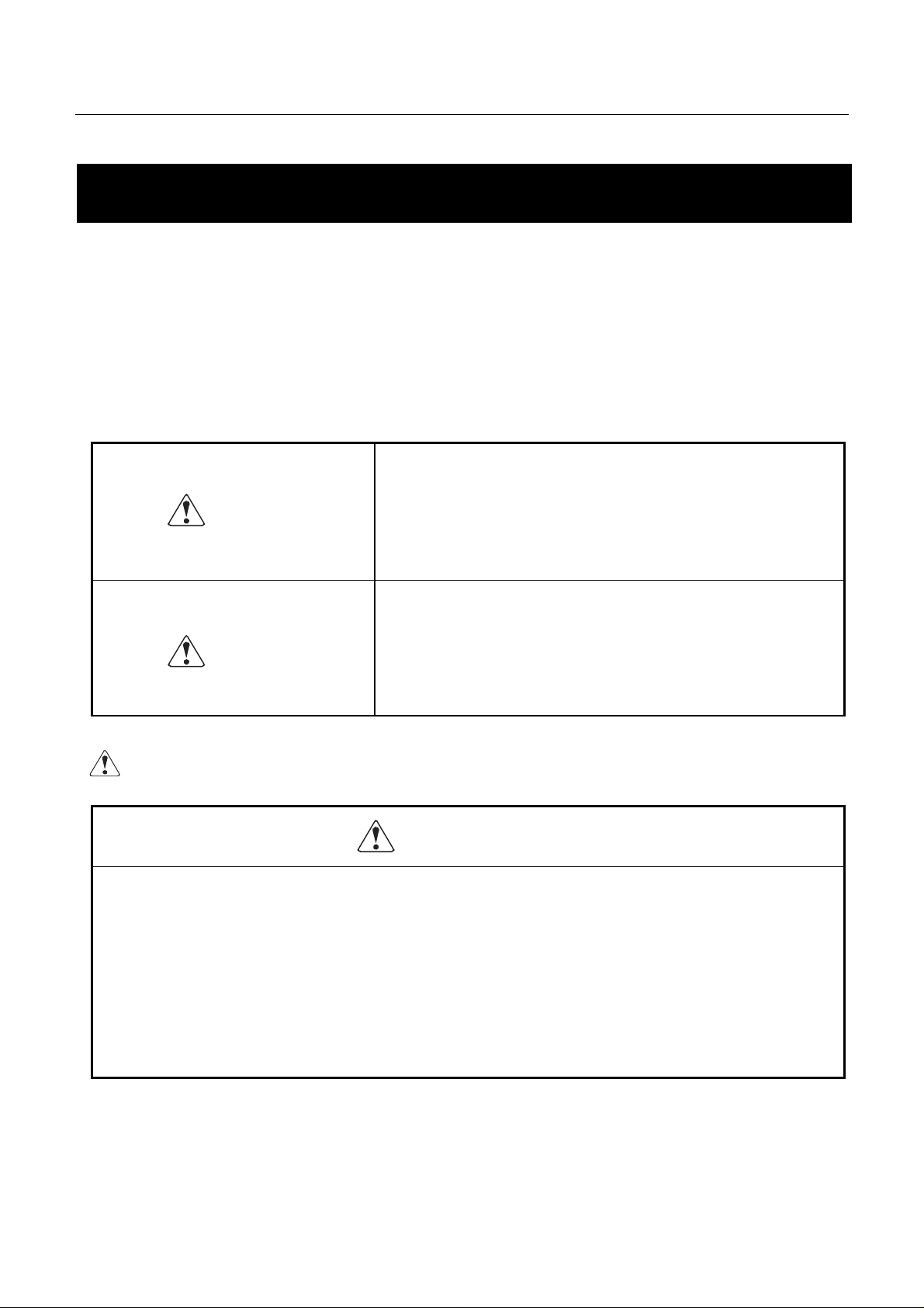
• Do not touch the print head or motor immediately after printing, since these parts will be very hot
and there will be a danger of burn in g your hand.
CITIZEN
Page 10

CBM-253 User’s Manual
CAUTION
• Do not place objects on top of this equipment. since there will be a danger of the objects falling off
or falling over , resulting in in ju ry .
• Do not us e or store t his equi pment i n locati ons tha t have fi re or mo isture, in loca tions t hat are
subje ct t o dir ect s unli ght , in l ocat io ns tha t ar e abnor mal ly hot suc h as close to hea ti ng equi pme nt ,
or in locations that are very humid or dusty, since t his will be a cause of breakdowns.
CITIZEN
Page 11

CBM-253 User’s Manual
CONTENTS
1. OUTLINE...................................................................................................................................................1
1. 1 Features.............................................................................................................................................1
1. 2
Cautions for installation....................................................................................................................1
1.3 General cautions................................................................................................................................2
2. BASIC SPECIFICATIONS......................................................................................................................4
2.1
Model classifications......................................................................................................................... 4
2.2 Printing specification s.......................................................................................................................4
2.3 Character specifications....................................................................................................................5
2. 4 Paper specifications...........................................................................................................................8
2. 5 Interfaces.........................................................................................................................................10
2. 6 Data buffer......................................................................................................................................10
2. 7 Paper and sensor..............................................................................................................................10
2. 8 Auto-cutter......................................................................................................................................10
2. 9 Drawer kick-out connector..............................................................................................................10
2. 10 Electrical specifications .................................................................................................................10
2.11 External appearance specifications .................................................................................................11
2.12 Environmental specifications..........................................................................................................11
2.13 Reliability specifications.................................................................................................................11
2.14 EMI standards and safety standards................................................................................................11
3. EXTERNAL APPEARANCE AND N AMES OF E ACH PART.........................................................12
3.1
External appearance and part names...............................................................................................12
3.2 Explanation of each part .................................................................................................................13
4. OPERATION...........................................................................................................................................15
4.1
Opening the printer cover ...............................................................................................................15
4.2 Opening the auto-cutter...................................................................................................................16
4.3 Setting the paper roll in the paper holder ........................................................................................17
4.4 Loading the paper............................................................................................................................18
4.5 Loading the paper when paper roll is sma ll ....................................................................................19
4. 6 Setting the printer cover back .........................................................................................................22
4. 7 Opening the print head....................................................................................................................23
4. 8 Serf-printing....................................................................................................................................24
4. 9 Hexadecimal dumping function......................................................................................................24
4.10 Pap er end detecting function...........................................................................................................25
CITIZEN
Page 12

CBM-253 User’s Manual
5. INTERFACE SPECIFICATIONS.........................................................................................................26
Serial inter face................................................................................................................................26
5.1
5.2 Parallel interface.............................................................................................................................28
6. DRAWER KICK-OUT CONNECTOR.................................................................................................30
7. DIP SWITCH SETTlNGS.......................................................................................................................32
8. FUNTIONS...............................................................................................................................................35
8.1
Command table...............................................................................................................................35
8.2 Details of commands.......................................................................................................................37
8.2.1 How to read each section...................................................................................................37
8.2.2
Detailed explanations.........................................................................................................38
8.3 Character code tables ....................................................................................................................106
8.3.1 Page 0 (International ch aracter set: When U.S.A characters have been selected)...........106
8.3.2 Page 1 (International ch aracter set: When U.S.A characters have been selected)...........107
8.3.3 International character sets..............................................................................................108
9. EXTERNAL DIMENSION...................................................................................................................109
CITIZEN
Page 13

CBM-253 User’s Manual
1. OUTLINE
This printer is a thermal line printer that is capable of being widely used with various types of data
communication terminals, POS terminals. or kitc hen printers, etc. Becaus e this printer uses a thermal line pri ntings
systems, high speed printing is possible Furthermore, this printer may be widely utilized for various applications due
to the incorporation of ample functions.
1. 1 Features
• Small size and light weight.
• High speed printing. (400 dot lines/second)
• Quiet operation and high reliability.
• Due to the head opening mechanism, maintenance such as head cleaning will be simple.
• RS-232C or Centroni cs interface are selectable.
• Bar code printing is available. (Using exclusive commands)
• The character size can be specified. (Standard size, double wide, double height, double wide and double
height. )
• International character sets for 11 countrie s ar e b uilt in.
• A drawer kick-out interface is built in.
• An auto-cutter is equipped.
• The receiving buffer size is selectable. (45 bytes or 4 K bytes.)
1. 2 Cautions for install ation
1. Concerning the use of this equipment, please carefully read the "Cautions for safe use", and carry out
operations following these cautions.
2. Confirm that the accessories listed below are included in addition to the printer main unit in this set of
equipment.
• Roll of paper.............................1 roll
• User's manual...........................1 manual
3. This equipment should not be operated or stored in locations that have fire or moisture, in locations that are
expos ed to di rect sunl ight, i n loca tions that have a bnor mall y high te mpera tures due to heati ng equ ipmen t or
hot equipment, in low locations, or in locations that are very damp or dusty.
4. This equipment should not be installed in locations where chemical reactions are generated, such as in
laboratories, etc.
1
CITIZEN
Page 14

CBM-253 User’s Manual
5. This equipment should not be installed in l ocations w here the air contains salt or toxic gases.
6. Install the printer on a flat, stable table top in a location having good ventila - tion. (Ensure that the ventilati on
holes are not blocked.)
7. Items should not be pla ced on top of this equipment.
8. Note t ha t t he us e of t hi s eq ui p men t c los e to a r a dio or tel evi s io n r ece iv er , or s ha ri ng t he sa me po wer s our ce
outlet may cause reception pr oblems in the radio or television.
9. Only use this equipment at the specified voltage and frequency.
10. Do not place objects on to p o f th e power cable or tread on top of the cable.
11. Do not pull or carry the main unit by holding the powe r cable or data cable.
12. Avoid connecting the power cable together with several other power cables to one power source outlet.
13. When pulling out the power cord, be sure to hold the plug while pulling it out.
14. Be sure to connect the connector properly. In particular, the internal terminals may be destroyed if the
connector is connected using the reverse polarity.
15. Be sure to set the power switch to OFF before mounting or removing the inter -face connector cable.
16. As far as possible, avoid over-lengthening the signal wire or connecting the printer to equipment that
gene ra te s no ise . I n si tua t ions w her e wi ri ng of t his ki nd m ust be c ar r ied o ut, ap pl y a deq ua te c ou nte r mea sur es
such as using sh ield e d w iring or twisted pair wirin g fo r ea c h s i gnal.
17. Only connect the prescribed solenoid to the drawer kick connector.
18. Ensure that there is a power source outlet close to the equipment, and make sure that this power source outlet
can be easily reached.
1.3 General cautions
1. Concerning the use of this equipment, please read the "Cautions for safe use", and carry out operations
following these cautions.
2. Do not carry out blank printing in the condition where there is no recording paper in the printing unit.
3. Take care not to touch the printin g un it of the th ermal print head with your bare hands.
4. W hen cleaning the hea d or plate n, please use the excl usive cleaning ki t for radio cassett e recorder on the
market etc.
5. When cleaning the surface of the main unit case, do not use thinners, truculence, benzene or ketene group
solvents, or chemical-impregnated cleaning cloths.
6. Avoid using this equipment in locations which are subject to large amounts of oil, iron powder, debris, dust,
etc.
7. Take car e not to dr op paper clips , valve core pi ns, for eign obj ects, e tc. i nto the main u nit, s ince thi s will
become a cause of breakdowns.
2
CITIZEN
Page 15

CBM-253 User’s Manual
8. Do not spill liquids or spray chemicals, etc . on to this equ ipm ent.
9. Do not subject this equipment to strong shock or vibration by standing on it. dropping it, hitting it, etc.
10. Carr y out the operation of the operating panel unit with care, since disordered operation will become a cause
of breakdowns and mistaken operation. Furthermore, absolutely do not operate the panel using sharp objects
such as the tip of a pen etc.
11. During operation, do not touch moving parts such as gears, or the electrical parts inside the main unit.
12. Take care not to injure yourself or cause damage to other objec ts from the edges of th e s heet metal.
13. If an abnormality occurs during use, immediately stop using the printer and remove the power cable from
the powe r source outlet.
14. If a breakdown occurs, do not attempt to disassemble the equipment. Be sure to leave the repair of this
equipment to Service personnel.
3
CITIZEN
Page 16

2. BASIC SPECIFICATIONS
2.1 Model classifications
CBM - 253 - ∗∗∗∗ ∗∗∗∗ ∗∗∗∗ ∗∗∗∗
CBM-253 User’s Manual
D: Drawer kick connecter is equipped
None: Not equipped
Power source voltage
120: AC 120V, 230: AC 230V
Character set
F: Inter national c har ac ters
interface
R: Serial, P: Parallel
2.2 Printing specifications
Printing method Direct heat coloring system (Direct thermal)
Printing direction Line feeding by friction feeding
Effective printin g area Effective Printin g w id th:
56mm 448 dots/line (Thermal paper)
53mm 424 dots/line (Thermal label paper)
Dot density Main scanning line density: 8 dots/mm. (203 dpi)
Number of columns 37 columns (Font 1 , Thermal paper)
49 columns (Font 2, Thermal label paper)
35 columns (Font 1, Thermal paper)
47 columns (Font 2, Thermal label paper)
4
CITIZEN
Page 17

Printing sp e ed 400 dot lines/second
(Approximately 11 lines/second when the line feeding amount is l/6 inch.)
However, depending on the combination of the communication t i me, data,
and control codes, the printing speed may be slower.
Paper feedi ng spee d 50 mm/second
(Approximately 11 lines/second when the line feeding amount is 1/6 inch.)
Line feeding pi tch l/6 inch (Default value)
Possible to change the pitch using the control codes
(Minimum width 1/203 inch)
2.3 Character specifications
CBM-253 User’s Manual
Character types : Alphanumeric characters 95 chara ct ers
Int ernational characters 32 characters
Character conf iguration 12 × 24 (Font 1 including 2-dot horizontal spacing)
9 × 17 (Font 2 including 2-dot horizontal spacing)
Font 1 is selected as the default.
Character size 1.25 × 3.0 (mm) (Font 1)
0.88 × 2.13 (mm) (Font 2)
Character enlargement rates Standard size, double wide. double height, double wide and height
5
CITIZEN
Page 18

CBM-253 User’s Manual
Number of columns
Font 1
Font 2
Standard size Double height Double wide
37
35
49
47
37
35
49
47
18
17
24
23
Double wide
and height
18
17
24
23
(Spaces between the characters are not included)
The figures on the top line show the situation when th erm al paper is selected, and the figures on the bottom line
show th e situ ation w h en th e rmal label pa per is selec t ed.
6
CITIZEN
Page 19
CBM-253 User’s Manual
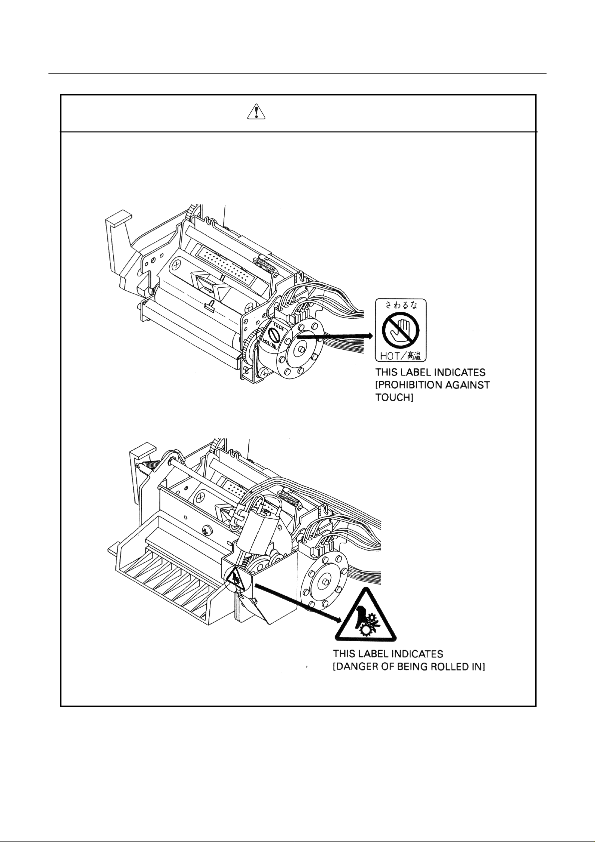
Available bar codes UPC-A, UPC-E, JAN- 13 (EAN), JAN-8 (EAN), CODE 39, ITF,
CODABAR, CODE 128
Type Printing samples Features
UPC-A
This is a fixed-length bar code that is
composed of 12 figures of numerals
only.
This is a fixed-length bar code that is
UPC-E
composed of 8 figures of numerals
only. This bar code is a shortened
version of UPC-A.
JAN- 13
This is a fixed-length bar code that is
composed of 13 figures of numerals
only.
JAN-8
This is a fixed-length bar code that is
composed of 8 figures of numerals
only.
This is a variable-length bar code
that is compose d of alphabetic
CODE 39
characters and nu m erals. The start
and stop ' * ' characters are attached
automatically.
ITF
This is an even-numbered variablelength bar code that is composed of
numerals only .
This is a variable-length bar code
CODABAR
that is compose d of alphabetic
characters. For the start and stop
characters, one of 'abcd' is required.
CODE 128
This is a variable-length bar code
that is co m pos ed of a n y of the 128
ASCII code characters.
Bar code specification Type/number of printing figures/bar code height/horizontal width (enlargement) /
presence of visible code Printing will be carried out according to the bar code data
specifications.
7
CITIZEN
Page 20

2.4 Paper specifications
Specified paper (Roll paper)
Thermal paper
Paper width : 60.0 mm± mm
Paper thickness : 65±5µm
Diameter of paper roll : φ83 mm maximum
Recommended p aper : TF50KS-EY Nihon Seishi Co., Ltd.
: TF50KS-E2C Nihon Seishi Co., Ltd.
Roll paper core : Internal diameter φ12.0 mm
: External diameter φ18.0 mm
* Absolu tely do not stick th e paper to th e core.
* The printing surface should be outside.
0
1
CBM-253 User’s Manual
Printing area
Thermal label paper
Paper width Paper thickness : 60.0 mm± mm
0
1
: 150µm maximum
(Base paper thickness + Label thickness)
Diameter of paper roll : φ83 mm maximum
Label size : Minimum 25 mm ~ maximum 100 mm
Recommended paper : HG76, HD75 Nihon Seishi Co., Ltd.
Roll paper core : Internal diameter φ25.4 mm
: External diameter φ33.4 mm
* Absolute ly do not stick the paper to the c ore.
* The printing surface should be outside.
8
CITIZEN
Page 21
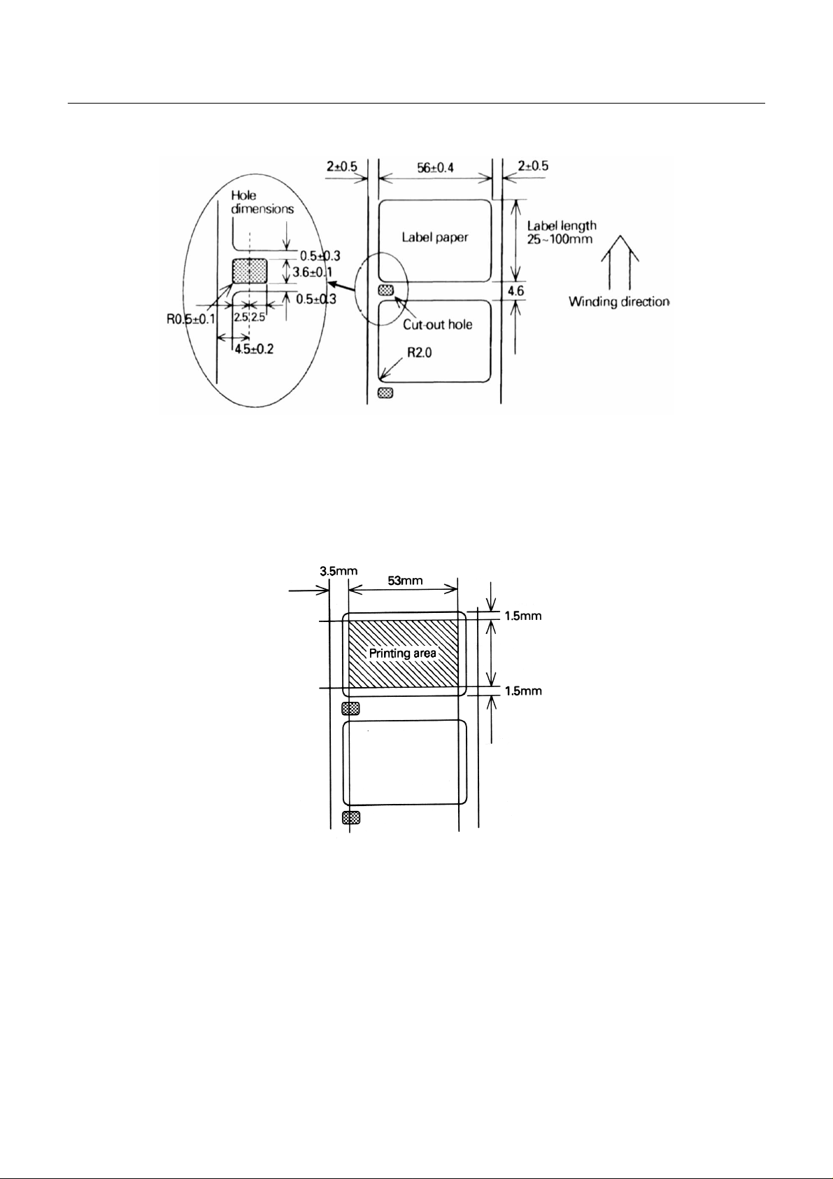
CBM-253 User’s Manual
• In order to allow the detection of the paper label length and label top position, cut-out holes should be
made between the paper labels according to the dimensions shown above.
• Do not use label paper that has different dimensions from that shown above.
Printing area
Note: Do not mix labels having differen t wid th s and length in the sa me ro ll of label paper.
Note : Have a surplus in the printing range in consideration of the flexing and the range of differences in the
printing paper.
9
CITIZEN
Page 22

2. 5 Interfaces
Serial interface (RS-232C)
Parallel interface
2. 6 Data buffer
4KB or 45B (Selectabl e by dip swit ch setting)
2. 7 P aper and sensor
Detection of whether there is paper or not. (Mechanical u nit)
Near-end detection (Paper holder unit)
2. 8 Auto-cutter
CBM-253 User’s Manual
Rotary system, full cu t type (AC-7)
Note: Auto-cu tter ope ration will not be po ssible w hile the printe r is printing .
Note: After switching on the printer. carry out cutting one time in order to determine the position.
Note: In case of using thermal label paper, paste of label may stick to cutter blade.
2. 9 Drawer kick-out connector
Drawer kick-out drive terminal × 2
Detection o f drawer o p en/cl os e ter mi nal × l
2. 10 Electrical specifications
Power source voltage AC 120V+10% 50/60Hz
AC 230V+10% 50/60Hz
(Selected according to the product destination)
Power cable For North America: 3-pin UL cable
For Europe: 3-pin Class 1 cable
Power consumption Approximately 20W (during character printing)
Approximately 40W (during full printing)
10
CITIZEN
Page 23

CBM-253 User’s Manual
2.11 External appearance specifications
Weight Approximately 2.2kg
External dimensions Refer to 'External dimensions' at the end of this manual.
2.12 Environmental specifications
Temperature Operating temperature 5°C~40°C
Storage tempe r at ure -10°C~5 0 °C (Exclud ing the reco rding p aper)
Humidity Operating humidity 35~80% (Non-condensing)
Storage humidity 30~90% (Non-condensing, excluding the recording paper)
2.13 Reliability specifications
Head lifetime P ulse resistance : 5 × 10⁷ pulses
Wear resistance : 30 km
(At a printing rate of less than 25.0%, with a resistance value change rate of 15% or less.)
Cutter lifetime 500,000 cuts (At no past e of label o n c ut ter blade.)
Please note that the above lifetime is not guaranteed value.
This value m ay c hang e dep en d in g o n i nstallation environment of printer unit.
2.14 EMI standards and safety standards
FCC Class A
VCCI Type 1
UL 1950
EN 60950
11
CITIZEN
Page 24
CBM-253 User’s Manual
3. EXTERNAL APPEARANCE AND NAMES OF EACH PART
3.1 External appearance and part names
12
CITIZEN
Page 25
CBM-253 User’s Manual
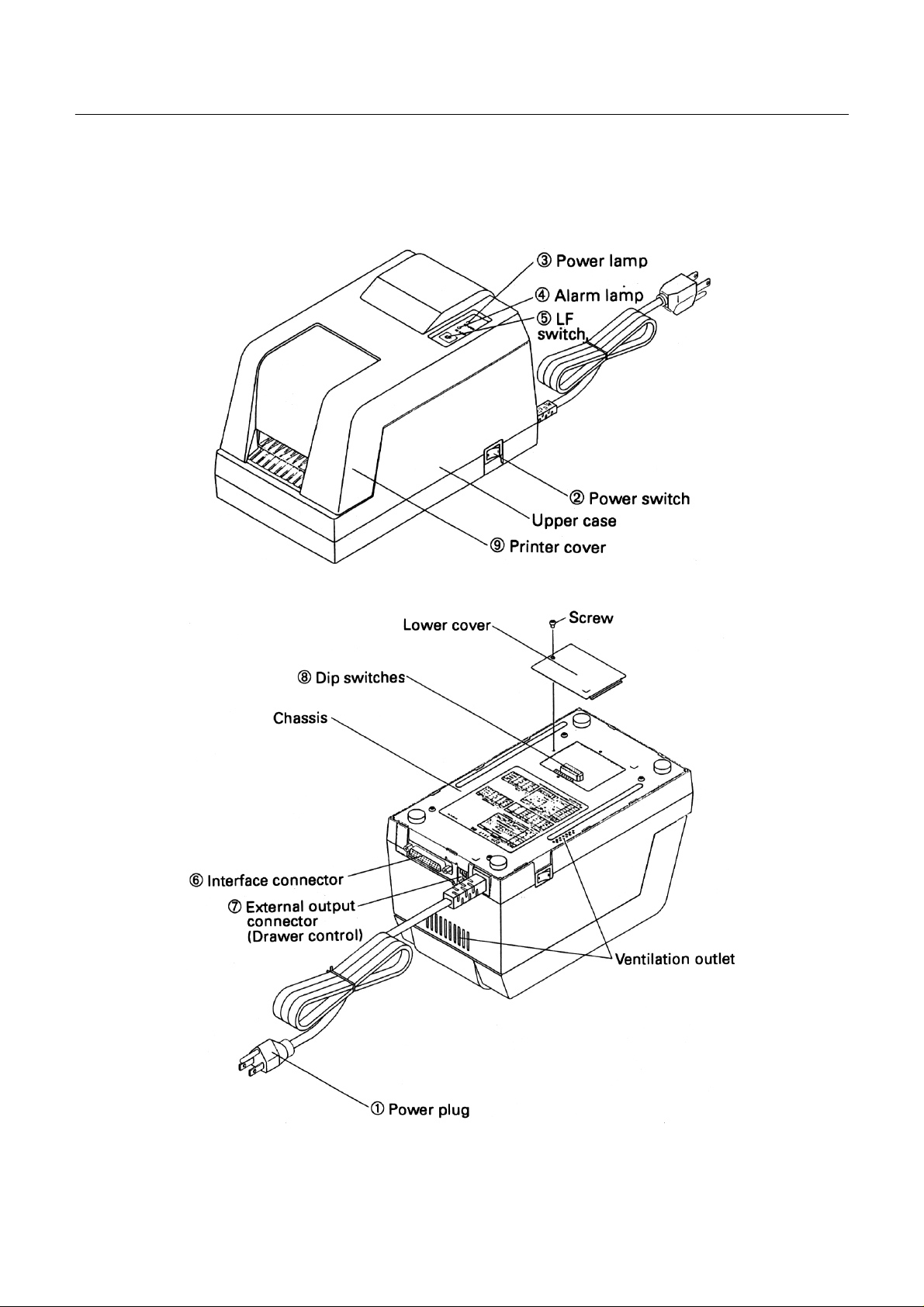
3.2 Explanation of each part
1 Power plug This plug should be inserted into a power source outlet of the specified voltage.
2 Power switch By setting this switch to ON, the printer initializati on operation will begin.
3 Power lamp This lamp will be lit when the power switch is ON, and will be off when the power
switch is OFF .
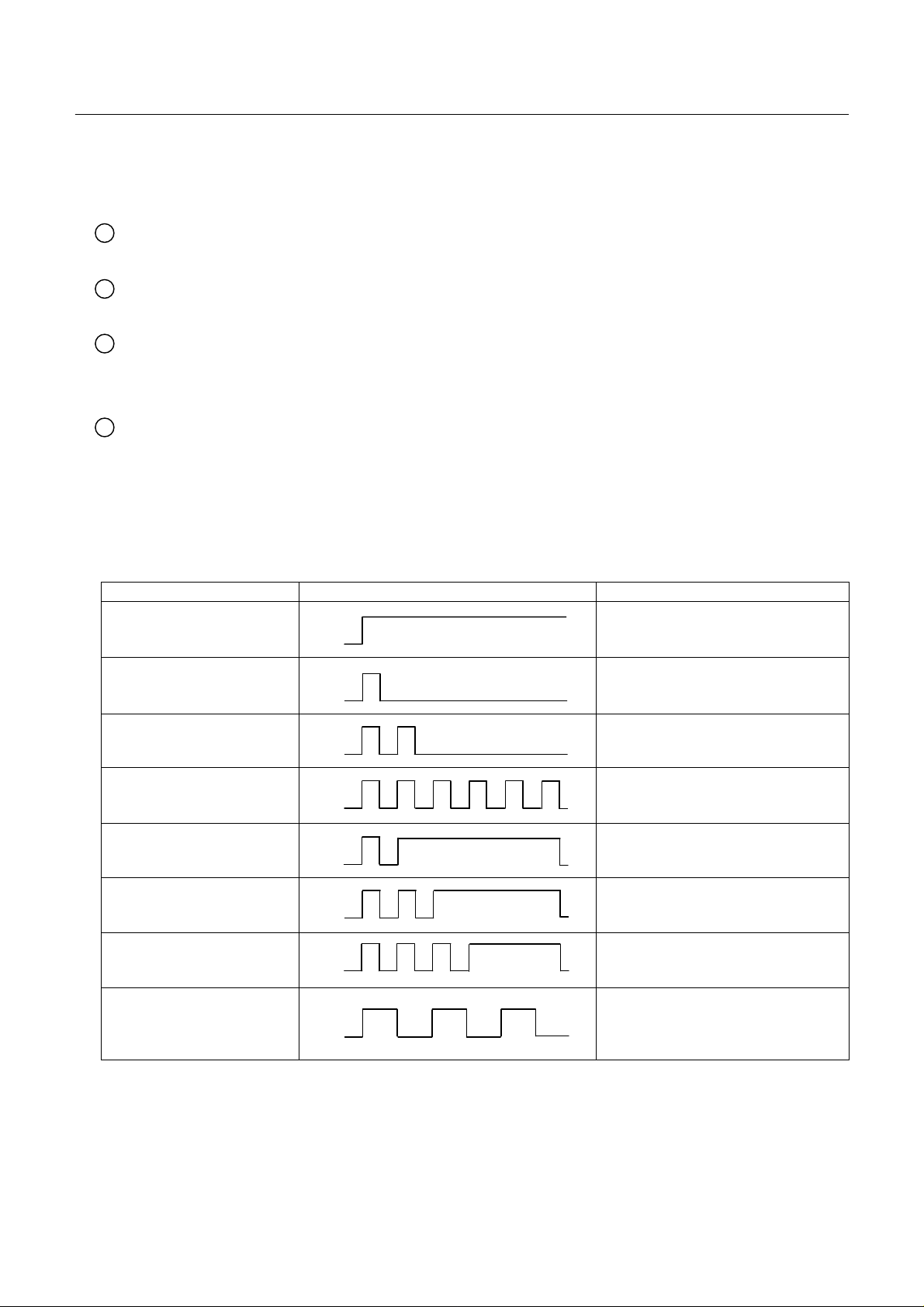
4 Alarm lamp This lamp will light in the printer error condition. The lamp will flash to indicate
the p rinter co n diti o n dur i n g errors su ch as w hen the pap e r has r un out, when the
head is open , or when th e he ad is ov erhe ating , and will also flash wh en th e p rinter
is in the condition of waiting for macro execution, etc.
Error display patterns
Error name Pa t t ern of flashing Conditions for resetting
Prin t er cover ope n
Head up
Paper near-end
Paper en d
Label detecting error
Memory checking error
Head thermistor error
Head overheating
Cutter motor locking
Waiting for macro execution
Waiting for label ejection
Waiting for test printing
Waiting for cutter operation
Lit
Off
Lit
Off
Lit
Off
Lit
Off
Lit
Off
Lit
Off
Lit
Off
Close the cover
Head down
Set the paper
Set the paper
Set the specified label paper and then
switch the power on a again
Resetting not possible *1
Resetting not possible *1
Automatic resetting when the
temperature lowers
Resetting not possible *1
Lit
Off
Press the LF switch
* 1 Contact service person.
13
CITIZEN
Page 26

CBM-253 User’s Manual
5 LF switch Pressing this switch carries out line feeding of the paper. When the printer is
waiting for macro execution, pressing this switch will carry out the execution.
When the power switch is switched on while this switch is being pressed, selfprinting will be carried out.
6 Interface connector This interface allo ws connection with various types of personal computers using a
cable. When making the connection, the power of the personal computer and the
printer should be switched off.
7 External output connector This connector is used for control of the drawer.
8 Dip switches These switches set the various functions.
9 Printer cover This cover should be opened and closed when replacing the printing paper.
14
CITIZEN
Page 27
CBM-253 User’s Manual
4. OPERATION
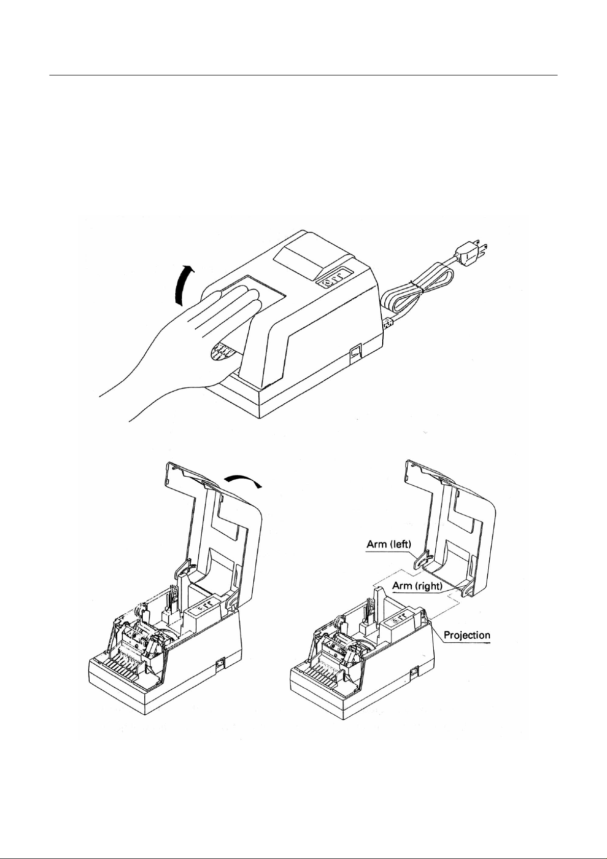
4.1 Opening the printer cover
The pr inter cover may be op ened by i nsert ing yo ur hand i nto the paper outlet o f the pr inter and lift ing u p the
cover in the direction shown by the arrow in the figure.
15
CITIZEN
Page 28
CBM-253 User’s Manual
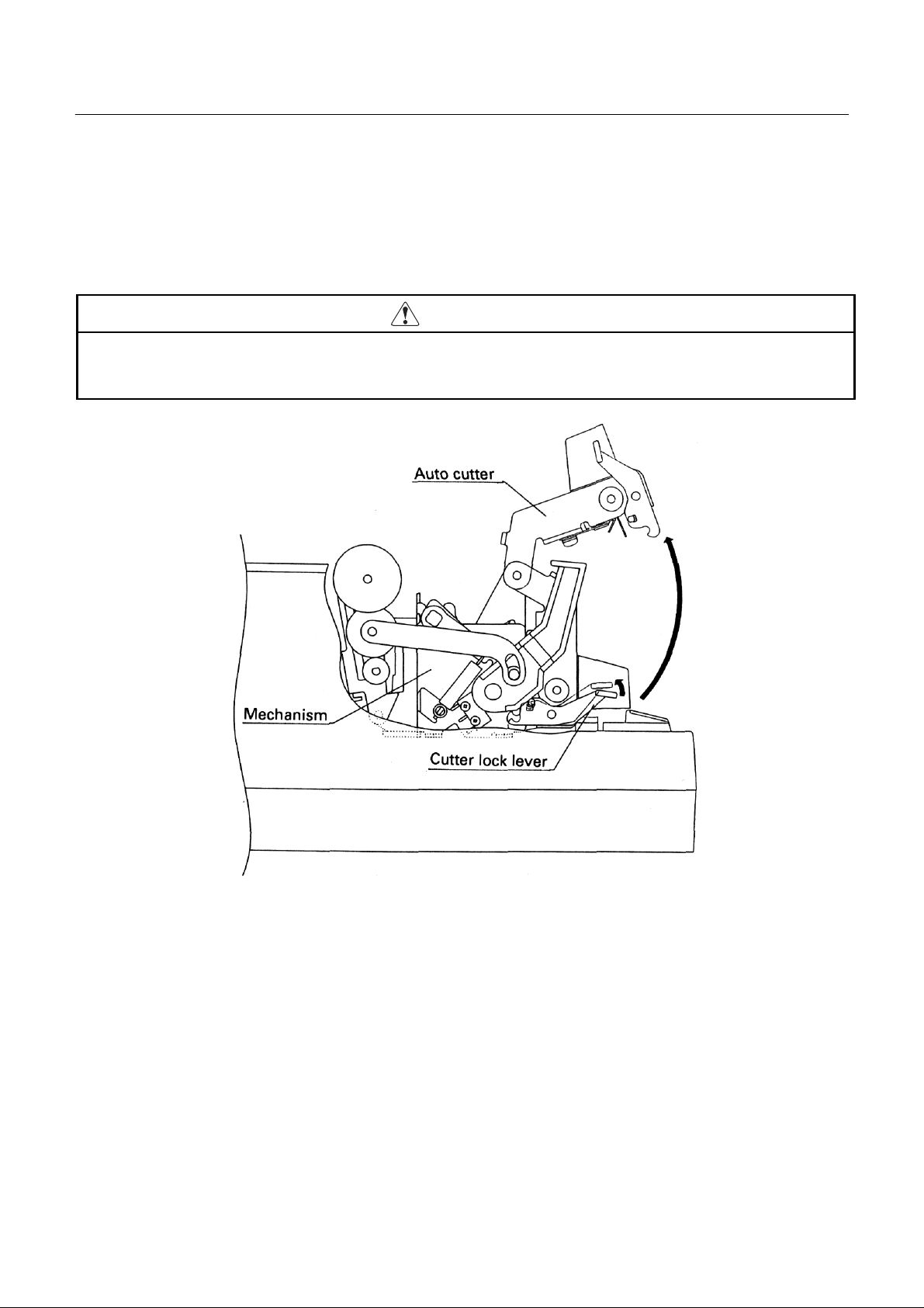
4.2 Opening the auto-cutter
To open the auto-cutter when the paper has become jammed in the printer or when the head is to be cleaned, life
up the auto-cutter while lifting th e cutter locking lever in the direction shown by the arrow.
CAUTION
• D o not touch the head or motor immediately after printing, since these par ts will be very hot and there
will be a danger of burning your hand.
After closing the auto-cutter, check that the cutter unit is firmly fixed in the mechanism by the cutter locking
lever. If the cutter unit is not firmly fixed, this will become a cause of paper jamming.
16
CITIZEN
Page 29
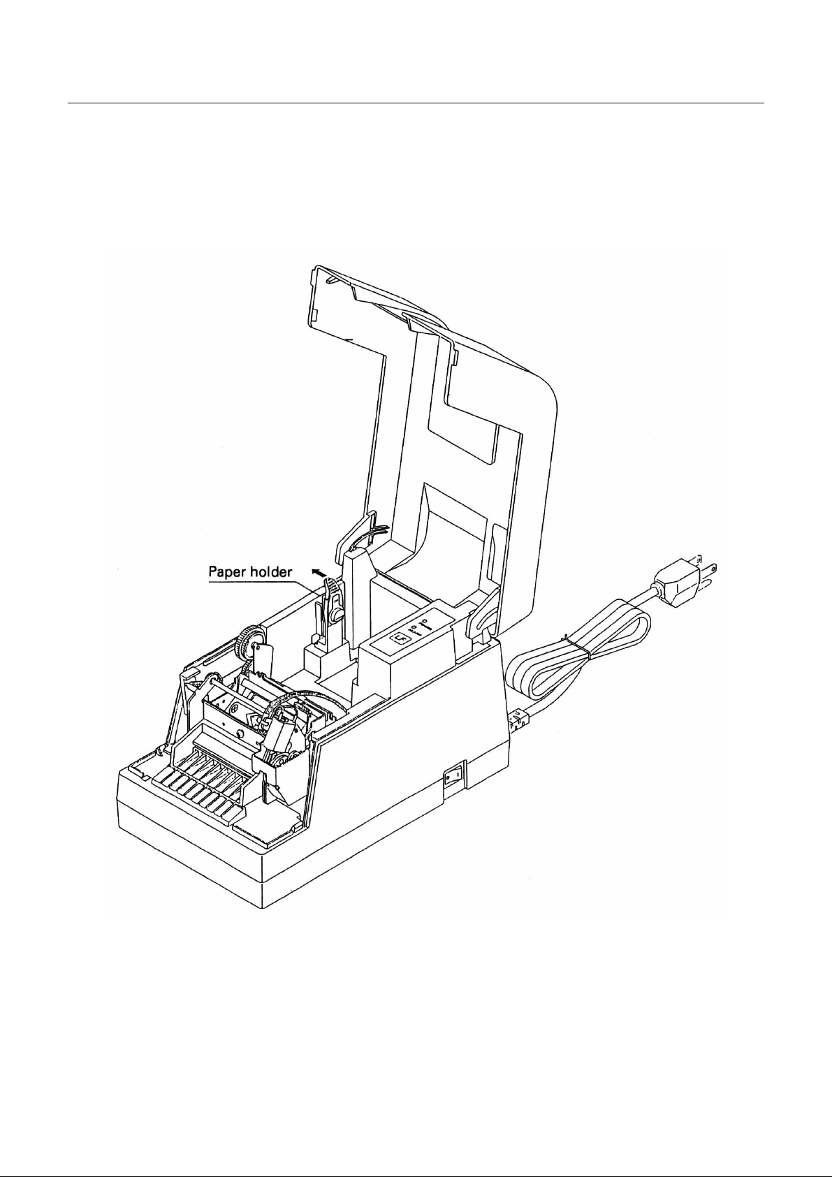
4.3 Setting the paper roll in the paper holder
Open the paper holder in the direction shown by the arrow and set the roll paper.
CBM-253 User’s Manual
17
CITIZEN
Page 30
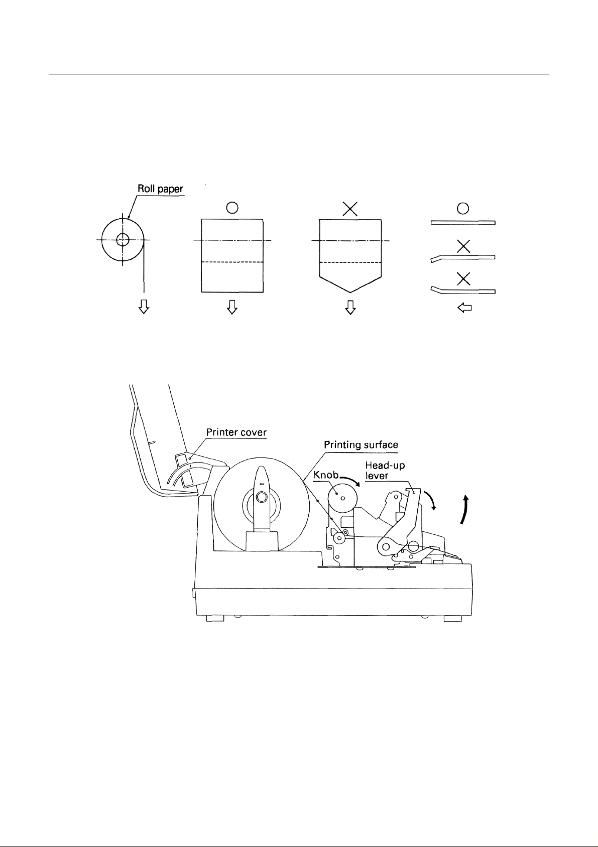
4.4 Loading the paper
1. Open the printer cover.
2. Cut the end of the roll of paper at right angles as shown in the figure.
3. Set the printing paper in the pape r holder as shown in the figure.
CBM-253 User’s Manual
* Make sure that the paper roll rotates smoothly.
4. Make sure the winding direction of the paper roll is correct, then insert the end of the printing paper into the
paper inlet in the rear part of the printer. (Printing surface should bc outside.)
5. Open the head-up lever (press it down forwards) to set the head up condition.
6. Use the knob to feed the printing paper up to the paper outlet.
7. Close the head-up lever. (Lift up the lever)
8. Close the printer cover.
18
CITIZEN
Page 31

CBM-253 User’s Manual
4.5 Loading the paper when paper roll is small
CAUTION
• D o not touch the head or motor immediately after printing, since these par ts will be very hot and there
will be a danger of burning your hand.
1. Open the printer cover.
2. Cut the end of the roll of paper at rig ht angles as shown in the figure.
3. Set the printing paper in the paper holder as shown in the figure.
* Confirm that the paper roll rotates smoothly.
19
CITIZEN
Page 32

CBM-253 User’s Manual
4. Lift up the auto-cutter lever to open the cutter.
5. Confirm the winding direction of the paper roll, then insert the end of the printing paper into the paper inlet
in the rear of the printer. (Note that printing surface should be outside.)
6. Open the head-up lever (press it down forwards) to set the head -up condition.
7. Using the kno b, feed th e p rinting paper until the paper comes out of the printer mechanism.
20
CITIZEN
Page 33

CBM-253 User’s Manual
8. Pull the paper that has come out of the printer mechanism and pass it thr ough the autocutter.
9. Clos e the auto -cutt er whi l e pu llin g the e n d of the paper that has pa sse d thr ough the auto-cutter.
10. Close th e head-up le ver.
11. Close th e printer cover.
21
CITIZEN
Page 34

CBM-253 User’s Manual
4. 6 Setting the printer cover back
Holding the printer cover in the approximately 90° open position, hook the right arm onto the right boss. Then
while pulling open the left arm, hook it on to the left boss to complete the mounting of the printer cover.
22
CITIZEN
Page 35

CBM-253 User’s Manual
4. 7 Opening the print head
CAUTION
• D o not touch the head or motor immediately after printing, since these par ts will be very hot and there
will be a danger of burning your hand.
1. Switch OFF the power switch. and remove the power plug from the mains outlet.
2. As shown in the figure, open the printer cover and the auto-cutter and then press the head-up lever down
forwards .
3. While sliding the head opening knob in the direction shown by 1 in the figure, lift up the head in the
direction shown by 2 in the figure to open the head.
Note: This operation should only be carried out when cleaning the head or platen.
23
CITIZEN
Page 36

CBM-253 User’s Manual
4. 8 Self-printing
A self-printing function is built in to this printer in order that the printing functions may be checked by the printer
itself. The following procedure should be used to operate this function:
1. Set the printing paper in the printer.
2. Switch off the power switch.
3. Clos e the printer cover and then switch the power switch to ON while pressing down the LF switch. Stop
pressing th e L F swit ch afte r conf irming th at the sel f-printing has started.
The printing will be started by the above operation, and the printer will change bac k to the normal mode after
com p letio n of the fixed lin e prin ting .
4.9 Hexadecimal dumping function
Usi ng thi s fu nct ion, it i s p ossib le t o ch eck t he c onte nts of da ta s ent fr o m the host unit by c onve ni ng th e dat a t o
hexadecimal code. The data transmission with the host unit can be monitored by monitoring the transmission
conditions. The following procedure should be used to operate this function:
1. Set the printing paper in the printer.
2. Switch off the power switch.
3. With the printer cover left open, switch the power switch to ON while pressing down the LF switch. By
closing th e p rin ter cov er, the p rin ter will chang e to the hexadecimal dumping mod e .
After carrying out the above operation. the printer will wait to receive the data.
To exit from this mode, switch off the printer power.
24
CITIZEN
Page 37

CBM-253 User’s Manual
4.10 Paper end detecting function
This printer includes functions that automatically detect when the remaining printing paper is running low and
stop the printing. The paper end detecting function detects when the paper has run out, and the paper near-end
detecting fu n ctio n detects when the remaining printing paper is running low.
The swi tchin g of the pa per near -end detecting fu nction b etween e nabled an d disabl ed is car ried out us ing the
<ESC c 4> command. When this functi on is set to enabled, the setti ng of the paper lengt h that is allowed between
the occurrence of the detection and the stopping of the printing should be carried out using the dip switches.
Note : In a situation in which the paper end is detected while printing on label paper, the data re mainin g i n th e
receiving buffer may not be printed at the intended position on the label.
25
CITIZEN
Page 38

5. INTERFACE SPECIFICATIONS
5.1 Serial interface
Specifications (Conform to RS-232C)
Synchronizing system : Asynchronous system
Handshaking : DTR/DSR control or Xon/Xoff control
Baud rates : 1200, 4800, 9600, 19200 (Selected by the user)
Data length : 7 or 8 bit length (Selected by the user)
Parity : Odd/Even/None (Selected by the user)
Signal level : Mark= -3 ~ -15V Logic '1'
: Space = +3 ~ +15V Logic '0'
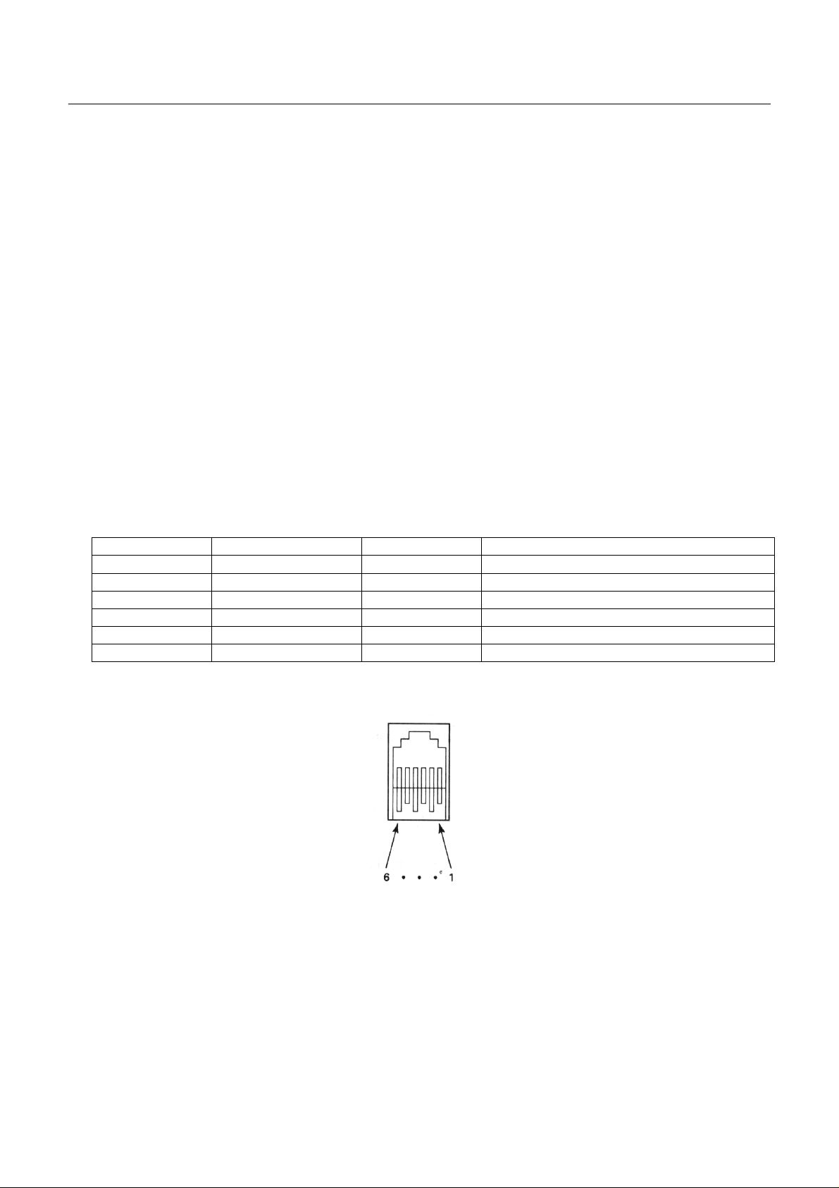
Compatible interface connectors
CBM-253 User’s Manual
Printer side : 25-pin connector 17-13250 (DDK) equivalent product
Cable side : 25-pin c onnector 17-23250 (DDK) equivalen t product
Connector's pin configuration
Connector pin Signal name Input/output Function
1 FG – Frame ground
2 TXD Output Sending data
3 RXD Input Receiving data
6 DSR Input Data set ready
20 DTR Output Data terminal ready
7 SG – Signal ground
Note: Shielded type cables should be used.
Explanation of input and output signals
(1) RxD
This is t he serial r eceiving da ta signal. O n the occurr ence of fra ming err ors, overru n errors or pa rity err ors,
this data will either be rejected or printed as ' ?'. according to the DSW2-7 switch condition.
26
CITIZEN
Page 39

CBM-253 User’s Manual
(2) DTR
When the DTR/DSR control has been selected, data or commands should be written when this signal is at
ready. If writing is carried out while this signal is at BUSY, a n overrun error will occur and the data will be
ignored. Data can be written into the input buffer even when printing is being carried out.
XD
(3) T
When receiving data while using Xon/Xoff control, an Xoff (13H) 'Data receiving not possible' signal will be
output whe n the remai ning space of the input b uffer inside t he printer becomes les s than 10 bytes. When th e
input buff er re maining space b ecome mor e than 20 bytes, a n Xon (11H) 'Data recei ving possibl e' sig nal will
be output. When sending stat us information while the DTR/DSR control is s elected, co nfirm that the DSR is
at ' space' before sendin g the data. I n the Xon /Xoff co ntrol, t he data should be sent re gardless of the D SR
condition.
(4) FG
This is a frame ground.
(5) SG
This is the common ground on the circuit board.
Receiving control
When DTR/DSR con trol has been selecte d, data will be received from the host when the DTR si gnal is at
'space' . Data receiving will not be po ssible when the DTR signal is at 'mark'.
When Xon/Xoff co ntrol has been selecte d, data will be receive d from the host side after the Xon si gnal has
been sent. However, data receiving will not be possible after the Xoff signal has been sent.
27
CITIZEN
Page 40

5.2 Parallel interface
Specifications (Conform to Centronics)
Data transmissio n format : 8-bit parallel
Synchronizing system : According to the strobe pulses
Handshaking : According to the BUSY signal
Signal level : TTL level
Compatible interface connectors
Printer side : Ribbon connector 57-40360 (DDK) equivalent product
Cable side : Ribbon co nnec t or 57-30360 (DDK) equivalent product
Connector' s pin configuration
Connector pin Signal name Input/output Function
l *STB Input Strobe signal
2~9 DATA 1-8 Input Input data
10 *ACK Output Request for next data
11 BUSY Output Processing is taking place
12 PE Output Paper end
13 (See note) +5V Output +5V DC
14-15 N/C
16 GND Ground
17 FG Frame ground
18 N/C
19-30 GND Twist e d pair return si g n als
31 *RESET Input Reset
32 * FAULT Output Error
33 GND Ground
34 COMPULSIO N Output COMPU L SION signal
35 (See note) +5V Output +5V DC
36 N/C
CBM-253 User’s Manual
The * mark represents a negative logic.
N/C means not connected.
Note: Shied type cables should be used.
Note: Pins 13 and 35 can not be used by the user (Pulled up by 3.3K )
28
CITIZEN
Page 41

CBM-253 User’s Manual
Explanation of input and output signals
(1) Input si gnals
DATA 1~8 : 8-bit parallel signals (Positive logic)
* STB : Strobe signal used when reading in 8-bit data (Negative logic )
* RESET : Signal that reset the whole printer. (Negative logic)
(2) Out put signa ls
* ACK : This is an 8-bit data requesting signal that is output as a BUSY FAULT PE pulse signal
at the end of the BUSY signal. (Negative logic)
BUSY : This signal indicates that the printer is in the BUSY condition. New data should be input
when this signal is LOW. (Positive logic)
FAULT : This signal changes to LOW when the printer is in the alarm condition. At this time, all
of the control circuits in the printer will stop. (Negative logic)
PE : This signal will be output when the printing paper runs out or runs low. (Positive logic)
COMPULSION : This signal outputs the drawer switch condition. When the switch is open, the signal will
be 'H' , and when t h e swi tch i s shorte d. th e signal will be 'L' .
(3) Other signals
+5V : GND N/C This is a +5V output that has been pulled-up by a 3 .3K resistance.
GND : This is the common ground on the circuit.
N/C : These pins are not connected.
Receiving control
When the BUSY signal is LOW, it will be possible to receive data fro m the host. When the BUSY signal is
HIGH, data receiving will not be possible.
29
CITIZEN
Page 42
6. DRAWER KICK-OUT CONNECTOR
(1) Drawer kick drive signal
The spec ified puls e will be output according to the specified pulse generating com m and (ESC <p>). When
using the parallel interface. it will be possible to dete rmine the condition of the drawer opening and closing
switch from pin 34 of the interface connector. When using the serial interface. the switch condition may be
determ ine d by utilizing the peripheral equipment status sendin g com m and (ESC <u>).
(2) Electrical ch aracteristics
Driving voltage : DC 24V
Driving current : Maximum 1A (Should be less than 510 ms)
SW signal : Signal level 'L' = 0~0.5V
'H' = 3~5V
CBM-253 User’s Manual
(3) Connector' s pin configuration
Connector pin Signal name Input/Output Function
1 FG – Frame ground
2 L1 Output Drawer l
3 SW Input Drawer opening and closing switch (* l)
4 Vp – Driving power source
5 L2 Output Drawer 2
6 GND – Signal ground
Used connector 285D-3660J- 100 (DDK)
Suitable connector 285D- 1660P-I06 (DDK) equivalent product
Note: It will no t be possible to switch both drawer 1 and 2 to ON at the same time.
Note: Drawer operation will no t be p ossible while th e p rin ter is printing.
Note: The duty should be kept to 20% or less.
Note: This connecto r is not t o be used for connection to telephone lines.
30
CITIZEN
Page 43

CBM-253 User’s Manual
WARNING!
• Do not attem pt to at t ach anything other than a solen o id, or to attac h a solenoid having a resistance value
of less than 24Ω to the drawer drive terminal. The attachment of unspecified equipment may cause
breakdown of the equipment or heat damage to the solenoid, resulting in the danger of fire or electric
shock.
(*1) Drawer opening and closing switch signal
This signal is pulled-up inside the printer using a resistance of 47KΩ.
(4) Driving circu it (Inside of printer)
31
CITIZEN
Page 44

CBM-253 User’s Manual
7. DIP SWITCH SETTlNGS
The dip switches can be found inside the printer unit by removing the lower cover on the base chassis part. If the
screw of th e lower cover is remo v e d. it will be possible to c h an g e th e d ip switch se ttin gs.
WARNING!
• Do not carr y out setting of dip switches while the power plug is still plugged in to the power outlet,
since this action may cause breakdowns or the danger of electric shock. Do not remove any screws
other than the screws tha t fix the rear cover, sinc e removing othe r screws may c ause breakdowns or the
danger of electric shock.
32
CITIZEN
Page 45

1 DSW1 (Used commonly by the serial and parallel interfaces)
DSW1 ON OFF
1
2
Printing density
(Refer to the table below.)
3 45 byte buffer 4K byte buffer
4 Thermal label paper Thermal paper
5
6
Printing stopping position
after near-end detection
7 (See note l) CR code valid CR code invalid
8 Spare
Note 1 : The DSW1-7 function is only used for parallel interfaces.
Printing density
DSW 1-1 DSW1-2 Level Density
ON ON 1
OFF ON 2
ON OFF 3
OFF OFF 4
Light
Dark
CBM-253 User’s Manual
Printing stopping position setting after paper near-end detection when the paper near -end detection has been
enabled.
DSW1-5 DSW 1-6 Stopping position
ON ON 0cm
OFF ON 50cm
ON OFF 100cm
OFF OFF 200cm
33
CITIZEN
Page 46

2 DSW2 (Only mounted in serial interface printers)
DSW1 ON OFF
1 Xon/Xoff control DTR/DSR control
2 Parity enabled No parity
3 Even parity Odd parity
4 7 bits 8 bits
5
6
7
Data rejected dur ing
a receiving error
(Refer to the table below.)
Baud rate
during a receiving error
8 Spare
Baud rate
DSW2-5 DSW2-6 Baud rate
ON ON 1200
OFF ON 4800
ON OFF 9600
OFF OFF 19200
CBM-253 User’s Manual
'?' character printed
Note 2 : The dip switch setting only become valid at the time when the power is switched on. According, if the
setting are changed when the power is on, the switching will not be effective.
34
CITIZEN
Page 47

CBM-253 User’s Manual
8. FUNCTIONS
8.1 Command table
Command Function Code
HT Horizontal tab command 09H 38
LF Printing, and paper line feeding 0AH 39
FF Printing, and moving to the top of the label 0CH 39
CR Printing command 0DH 41
ESC SP Setting of the amount of space to the right of
the character
20H n 42
1B
H
ESC ! Block setting of the printing mode 1BH 21H n 43
ESC % Specifying/releasing of the downloading
character set
25H n 44
1B
H
ESC & Defining of downloading characters 1BH 26H s n m
[a pl p2 · · · ps × a] m-n+1
ESC * Specifying of the bit image mode 1BH 2AH m n1 n2[d] k 48
ESC Specifying/releasing of the underlining 1BH 2DH n 50
ESC 2 Setting of th e l/6 inch line feeding amount 1BH 32H 51
ESC 3 Setting of the line feeding amount in
minimum paper feeding pitch units
33H n 52
1B
H
ESC = Data input control 1BH 3DH n 53
ESC @ Printer initialization 1BH 40H 54
ESC D Setting of the horizontal tab positions 1BH 44H [n]k 00H 55
ESC E Specifying/releasing of the highlighting 1BH 45H n 56
ESC G Specifying/releasing of the double printing 1BH 47H n 57
ESC J Printing, and paper feeding in minimum pitch
units
4AH n 58
1B
H
ESC R Selection of international characters 1BH 52H n 59
ESC V Specifying/releasing of 90° right turned
characters
56H n 60
1B
H
ESC a Selection of printing position justificatio n 1BH G1H n 61
ESC c 3 Selection of the effective paper end detector
for output of the paper end signal
ESC c 4 Selection of the effective paper end detector
for stopping the print ing
63H 33H n 62
1B
H
63H 34H n 64
1B
H
ESC c 5 Enabling/disabling of the panel switch 1BH 63H 35H n 65
ESC d Printing, and line feeding of n lines 1BH 64H n 66
ESC i Full cutting 1BH 69H 67
ESC p Specified pulse generation (Drawer kick out) 1BH 70H m n1 n2 68
Reference
page
46
35
CITIZEN
Page 48

CBM-253 User’s Manual
Command Function Code
Reference
page
ESC t Selection of the character code table 1BH 74H n 69
ESC v Sending of the printer status 1BH 75H n 70
ESC u Sending of the peripheral equipment status 1PH 76H 71
ESC { Specifying/releasing of inverted printing 1BH 7BH n 72
ESC $ Specifying of absolute positions 1BH 24H n1 n2 73
ESC ¥ Specifying of relative positions 1BH 5CH n1 n2 75
GS FF Printing, and label ejection (including cutting) 1DH 0CH 76
GS k Bar code printing 1DH 6BH n ['d']k 00H 77
GS w Selection of bar code horizontal size 1DH77H n 82
GS h Selection of bar code height 1DH 68H n 83
GS H Selection of visual code printing position 1DH 48H n 83
GS f Selectio n of visual code font 1DH 66H n 84
GS c Printing o f c ount er 1DH 63H 86
GS C0 Setting of the numbering printing mode 1DH 43H 30H m n 87
GS C1 Setting of the numbering counting mode (A) 1DH 43H 31H n1 n2
n3 n4 n5 n6
GS C2 Setting of the numbering counter 1D
32H n1 n2 92
H 43H
GS C; Setting of the numbering counting mode (B) 1DH 43H 3BH "N 1" 3BH "N2" 3BH
"N4"3BH "N5"3BH
H
2AH n1 n2[d]n1 × n2 × 8
H
GS * Definition of the downloading/bit image
"N3"3B
1D
89
95
95
GS / Printing of the downloading/bit image 1DH 2FH m 98
GS : Starting/finishing of the macro defining 1DH 3AH 99
GS ^ Macro execution 1DH 5EH n1 n2 n3 100
GS < Initialization of the printer mechanism 1DH 3CH 101
GS A Correction of the label top position 1DH 41H m n 102
GS R Specifying/releasing of the black/white
inverted characters
52H n 105
1D
H
Note : n, n1, n2, n3, m, a. s, p, and d in the table represent the parameters of each commend.
Note : [ ] k in the table represents a repetition carried ou t k times.
Note : ' ' in the table represents an ASCII character.
Note : " " in the table represents a string of ASCII characters.
36
CITIZEN
Page 49

CBM-253 User’s Manual
8.2 Details of commands
8.2.1 How to read each section
xxxx
[Name] This is the command name
[Code] In the line up of codes making up the command, < >H indicates hexadecimal notation,
< >B indicates binary notation, and < > indicates decimal notation. [ ] k represents a
repetition carried out k times.
[Function] This section indi cates the func tion of the command.
[Item requiring caution] When necessary, items that require caution are written in this section.
[Initial values] For co mmands that are accompanied by arguments, the initial values are written in this
section.
[Referen ce] Other command s rel at ed t o th e use of t he c ommand are written in this section.
[Program example] Indicates a coding example using BASIC language.
[Printing r esult] Indicates the printing res ult obtained by exec uting the progra m written above. Howe ver.
the scale reduction of the printing result given in this section will differ from that of the
actual printing result.
37
CITIZEN
Page 50

CBM-253 User’s Manual
8.2.2 Detailed explanations
HT
[Name] Horizontal tab command
[Code] <09>H
[Function] Moves the printing position to the next horizontal tab posit ion.
• This command will be disregarded if the next horizont al tab posi t i on has not been set.
[Item requiring cautio n ]
• The horizontal tab positions should be set using ESC D.
• In the initial settings. the horizontal tab positions will bc set every 8 characters in font 1.
(At the 9th. 17th, and 25th columns.)
[Reference] ESC D
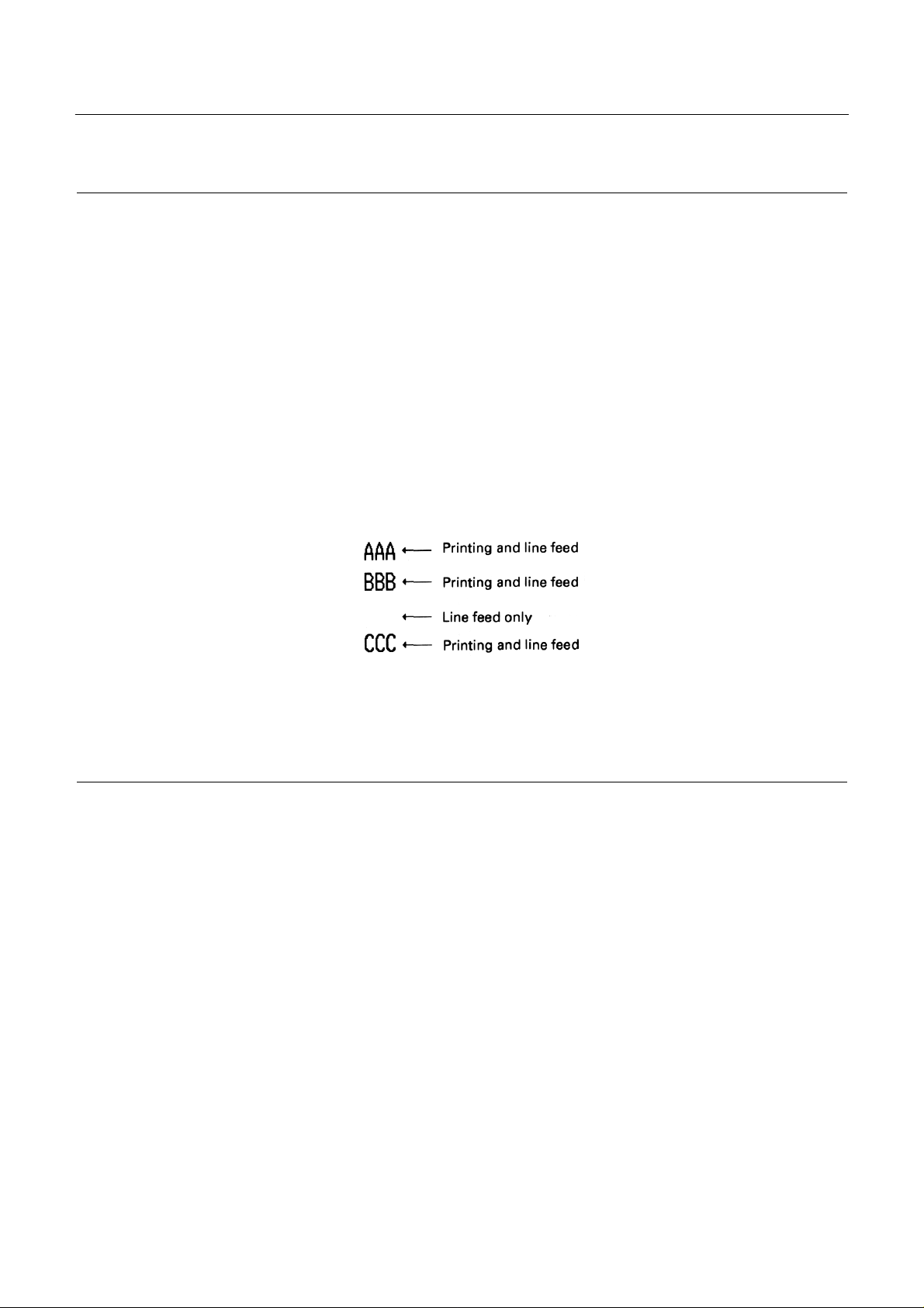
[Program example]
LPRINT "0123456789012345678901" ;
LPRINT CHR$ (&HA) ;
LPRINT CHR$ (&H9) + "AAA" ;
LPRINT CHR$ (&H9) + "BBB" ;
LPRINT CHR$ (&HA) ;
LPRINT CHR$ (&H1B) + "D" ;
LPRINT CHR$(3) + C}R$(7) + CHR$(14) + CHR$(0) ;
LPRINT CHR$(&H9) + "AAA" ;
LPRINT CHR$ (&H9) + "BBB" ;
LPRINT CHR$ (&H9) + "CCC" + CHR$(&HA) ;
[Print i n g re s u l t]
38
CITIZEN
Page 51
CBM-253 User’s Manual
LF
[Name] Printing, and paper line feeding
[Code] <0A>H
[Function] Prints the data in the print buffer, and carries out line feeding based on the set line feeding
amount.
• The next printin g start position will be at the head of the line.
[Reference] ESC 2, ESC 3
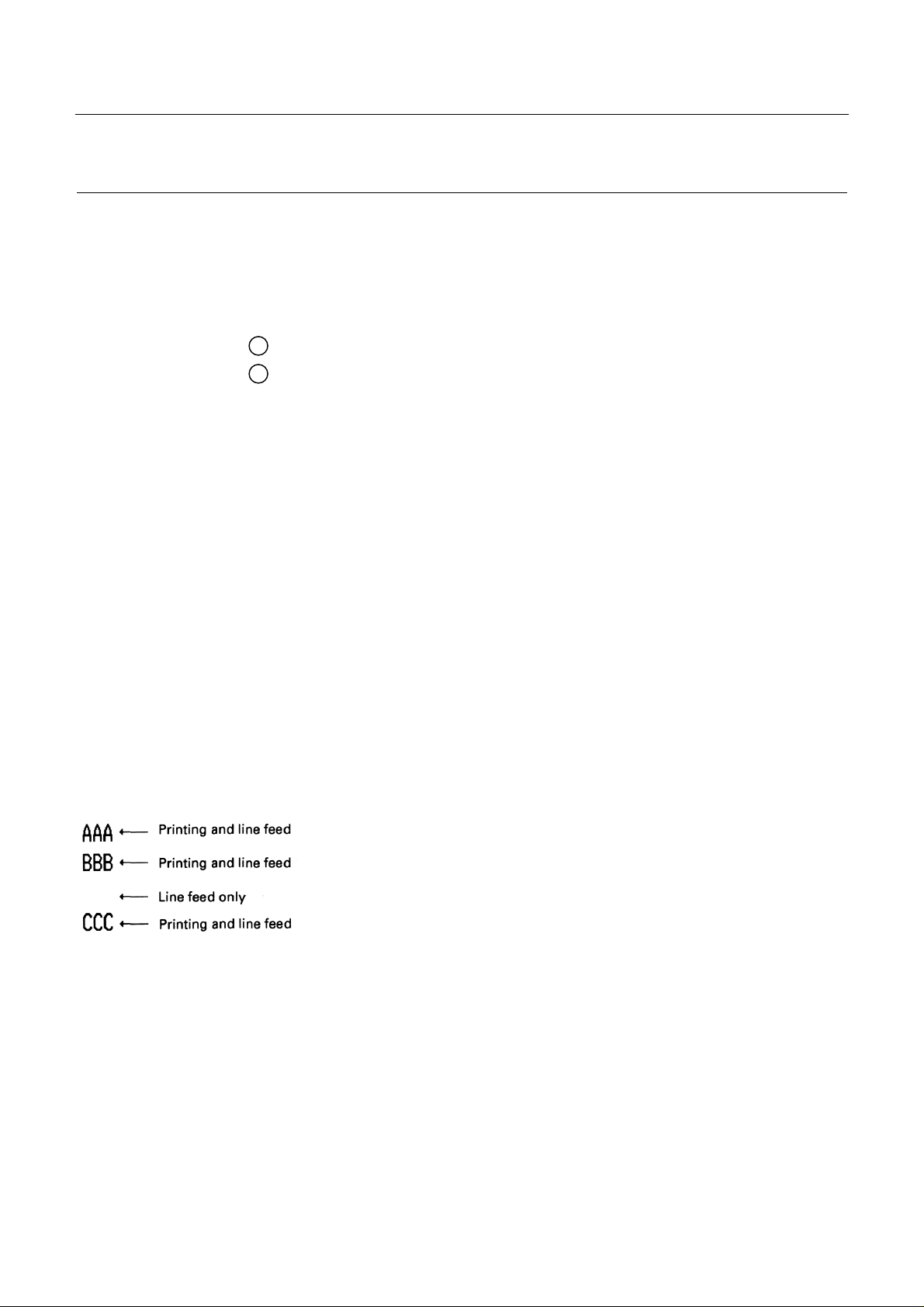
[Program example] [Printing result]
LPRINT "AAA" + CHR$ (&HA) ;
LPRINT "BBB" + CHR$(&HA) ;
LPRINT CHR$ (&HA) ;
LPRINT "CCC" + CHR$ (&HA) ;
FF
[Name] Printing, and moving to the top of the label
[Code] <0C>H
[Function] Prints the data in the print buffer, and moves to the top of the next label.
[Items requiring c aution ]
• This com mand will on ly be e ff ect iv e when label printings has been selected.
• After sending a one-label portion of printing data, be sure to send an <FF> or <GS FF>
command.
39
CITIZEN
Page 52

• After the label paper has been delibera tely moved by t he user, it will not be possible to
correctly move to the top of the label using this command. Accordingly, carry out the
moving to the top of the label using the LF switch or by executing the <GS < >
command.
[Reference] GS FF
[Program example]
LPRINT "AAA" + CHR$ (&HA) ;
LPRINT "BBB" + CHR$(&HA) ;
LPRINT CHR$(&H0C) ;
LPRINT "AAA" + CHR$ (&HA) ;
[Print i n g re s u l t]
CBM-253 User’s Manual
40
CITIZEN
Page 53
CR
[Name] Printing command
[Code] <0D>H
[Function] 1 When DSW1-7 is OFF, this command will be disregarded.
2 When DSW1-7 is ON, the data in the print buffer will be printed, and line feeding will
be carried out based on the set line feeding amount.
• The next printin g start position will be at the head of the line.
[Items requiring c aution ]
• This command will only be effective for parallel interface printers.
CBM-253 User’s Manual
[Reference] LF
[Program example]
LPRINT "AAA" + CHR$ (&HD) ;
LPRINT "BBB" + CHR$ ( & HD ) ;
LPRINT CHR$ (&HD) ;
LPRINT "CCC" + CHR$ (&HD) ;
[Print i n g re s u l t]
41
CITIZEN
Page 54

CBM-253 User’s Manual
ESC SP n
[Name] Setting of the amount of space to the right of the character
[Code] <1B>H <20>H <n>
[Defined ran g e ] 0 ≤ n ≤ 32
[Function] Sets the amount of space to the right of the character in dot units (1/203 inch units).
[Items requiring c aution ]
In double wide mode, th e amount of space to t he right of the character will become two
times the set amount.
[initial value] n = 0
[Program example]
LPRINT CHR$ (&H1B) + " " + CHR$ (0) ;
LPRINT "AAAAA" + CHR$ (&HA) ;
LPRINT CHR$(&H1B) + " " + CHR$(1) ;
LPRINT "AAAAA" + CHR$ (&HA) ;
LPRINT CHR$(&H1B) + " " + CHR$(12);
LPRINT "AAAAA" + CHR$ (&HA) ;
[Print i n g re s u l t]
42
CITIZEN
Page 55

ESC ! n
[Name] Block setting of the printing mode
[Code] <1B>H <21>H <n>
[Defined range] 0 ≤ n ≤ 255
[Funct ion] Specifies the printing mode.
Bit Function
0 Character font Font l Font 2
1 Not defined
2 Not defined
3 Highlighting Release Specify
4
5
6 Not defined
7 Underlining Release Specify
Double height
enlargement
Double wide
enlargement
CBM-253 User’s Manual
Value
0 1
Release Specify
Release Specify
[Items requiring c aution ]
By specifying both the double height enlargement and the double wide enlargement, the
double wide and double height enlarged character will be formed. Although underlining
will be applied to th e full wi dth of the pri nting cha r acters. underlining will not be applied
to parts tha t hav e be e n s ki p ped usi n g t he HT com ma n d. Furt her , under lini ng will also not
be applied to characters that have been rotated 90° rightward.
The wi dth of the under lining will be the widt h that has been specifi ed usin g <ESC ->.
(The default will be a 1 dot width.) In a situation where double height enlarged characters
and ordinary characters are mixed together on one line. a layout will be adopted in which
the underlining will coincide.
43
CITIZEN
Page 56

[Initial value] n = 0
[Reference] ESC E, ESC –
[Program example]
LPRINT CHR$(&H1B) + "!"+ CHR$ (&H00) + "H " ;
LPRINT CHR$ (&H1B) + "!" + CHR$(&H01) + "H " ;
LPRINT CHR$(&H1B) + "!"+ CHR$ (&H08) + "H " ;
LPRINT CHR$(&H1IB) + "! "+ CHR$(&H10) + "H " ;
LPRINT CHR$(&H1B) + "!"+ CHR$ (&H20) + "H " ;
LPRINT CHR$(&H1B) + "!"+ CHR$(&H80) + "H " ;
LPRINT CHR$(&H1B) + "!"+ CHR$ (&HB9) + "H " ;
LPRINT CHR$ (&HA) ;
CBM-253 User’s Manual
[Print i n g re s u l t]
ESC % n
[Name] Specifying/releasing of the downloading character set
[Code] <1B>H <25>H <n>
[Defined range] 0 ≤ n ≤ 255
44
CITIZEN
Page 57

[Function] Specifies or releases the downloading character set.
• Only the lowest bit of n will be valid.
When n = <*******1>B, the d o wn lo ad i n g charac ter set is spe ci fied.
When n = <*******0>B, t h e d o w nload i n g c h aracte r set is released.
(Specifies the internal character set)
[Items requiring c aution ]
It wil l not be possib le to de fine d ownloa ding cha racte rs and do wnloa ding bit image s at
the same time.
[Initial value] n = 0
[Reference] ESC &
[Program example]
CBM-253 User’s Manual
GOS UB S ET CHR
LPRINT CHR$(&H1B) + "%" + CHR$ (0) ;
LPRINT "@A" + CHR$ (&HA) ;
LPRINT CHR$ (&H1B) + "%" + CHR$ (1) ;
LPRINT "@A" + CHR$(&HA) ;
END
SETCHR :
LPRINT CHR$ (&H1B) + "&" ;
LPRINT CHR $ (3) + "@" + "A" ;
FOR J=1 TO 2
READ REP
LPRINT CHR$ (REP) ;
FOR I=1 TO REP*3
READ D
LPRINTCHR$ (D) ;
NEXT I
NEXT J
DATA 6
DATA &HFF, &H80, &H00
DATA &H 80, &H80, &H00
DATA &H 80. &H80, &H00
DATA &H 80. &H80, &H00
DATA &HFF, &HFF, &HFF
DATA &HFF, &HFF, &HFF
DATA 12
DATA &HFF, &HFF, &HFF
DATA &H 80, &H07, &HF9
DATA &H80, &HFF, &HF9
DATA &H87, &HFE, &H01
DATA &H9F, &H06, &H0l
DATA &HF8. &H06, &H0 1
DATA &HF8. &H06, &H0 1
DATA &H9F, &H06, &H01
DATA &H87, &HFE, &H0 l
RETURN
DATA &H80, &HFF, &HF9
DATA &H 80, &H07, &HF9
DATA &HFF, &HFF, &HFF
45
CITIZEN
Page 58

CBM-253 User’s Manual
[Print i n g re s u l t]
ESC & s n m [a [p] s x a] m - n + 1
[Name] Defining of downloading characters
[Code] <1B>H <26>H <s> <n> <m> [<a> <p1> <p2> .....<ps x a>] m-n+ 1
[Defined ranges] s = 3
32 ≤ n ≤ m ≤ 126
0 ≤ a ≤ 12 (Font 1)
0 ≤ a ≤ 9 (Font 2)
0 ≤ p1 .... ps × a ≤ 255
[Function]
Defines the alphanumeric and Kana character downloading character font.
s indicates the number of bytes in the vertical direction.
n indicated the starting character code, and m indicates the finishin g character code.
When defining only 1 character, n should be made equal to m.
The character codes that may be defined are the total of 95 characters of ASCII code
in the range between <20>H and <7E>H.
a indicates the number of dots defining the horizontal direction.
p is the dat a for defi nin g, a nd in dicat es a patt ern t hat is an a -pot porti on f ro m the l eft
margin in the horizontal direction. The remaining pattern to the right side will be filled
up with spaces, and the number of pieces of data for defining will be s × a.
Once the downloading char acters have been defi ned, the chara cters will remain valid
until other characters are defined, or until the ESC @ or GS * commands are executed,
or until the power is switched off.
46
CITIZEN
Page 59

[Items requiring c aution ]
It will not be possible to define the downloading characters and the downloading bit
images at the same time. When this command is executed. the defined downloading bit
imag e c o nt ents will be cle ared .
[Initial value]
The initial values will be the sam e as for the in tern al character set.
[Reference] ESC %
[Example]
CBM-253 User’s Manual
Each bit of the data is made up o f ' 1 ' dots that will be printed and '0' do ts that will not be printed.
[Program example] [Printing result]
Refer to th e p rog ram examp le and th e prin ti n g resu lt fo r ESC % on pa ge 45-46.
47
CITIZEN
Page 60

ESC ∗∗∗∗ m n1 n2 [d] k
[Name] Specifying of the bit image mode
[Code] <1B>H <2A>H <m> <n1> <n2> [<d>] k
[Defined ranges] m = 0, 1, 32, 33
0 ≤ n1 ≤ 255
0 ≤ n2 ≤ 3
0 ≤ d ≤ 255
k = n1 + 256 × n2 (m = 0, 1)
k = (n1 + 256 × n2) x 3 (m = 32, 33)
[Function]
CBM-253 User’s Manual
This command specifies the bit image of mode m with regard to the number of dots
specified by n1 and n2.
• The number of dots for printing will be divided by 256, and the quotient will become
n2 with the remainder becoming n1, Accordingly, the number of dots in the horizontal
direction w ill be n1 + 256 × n2.
• In a situati on where t he b it ima ge data inp ut exce eds th e dot positi ons t hat a re ca pabl e
of being printed on o n e line, t he por t i on of data in excess will be rejected for reading.
• d is the bit image data. W hen the data is to be printed, the corresponding bit should be
set to 1 , and data which is no t to be printed should have the corresponding bit set to 0.
• The bit image m ode selecte d using m will be as shown below :
Vertical direction Horizontal direction
m Mode
0 8-dots single density 8 67 DPI 101 DPI 224
1 8-dots double density 8 67 DPI 203 DPI 448
32 24-dot single density 24 203 DPI 101 DPI 224
33 24-dot double density 24 203 DPI 203 DPI 448
Number of dots Dot density Dot density
Maximum
number of dots
48
CITIZEN
Page 61

[Items requiring c aution ]
[Example]
CBM-253 User’s Manual
When the value of m is outside the conditions, data after n 1 will be processed as ordinary
data. After completion of the bit image printing, the mode will return to normal data
processing.
Printing result
[Program example]
LPRINT CHR$ (&H1B) + "*" ;
LPRINT CHR$(0) + CHR$(20) + CHR$(0) ;
GOSUB IMG1
LPRINT CHR$ (&HA) ;
LPRINT CHR$ (&H1B) + "*" ;
LPRINT CHR$ (1) + CHR$ (20) + CHR$ (0) ;
GOSUB IMG1
LPRINT CHR$(&HA) ;
LPRINT CHR$(&H1B) + "*" ;
LPRINT CHR$ (32) + CHR$ (20) + CHR$ (0) ;
GOSUB IMG2
LPRINT CHR$ (&HA) ;
LPRINT CHR$(&H1B) + "*";
LPRINT CHR$(33) + CHR$ (20) + CHR$(0) ;
IMG1:
LPRINT CHR$ (&HFF) ;
FOR I=1 TO 18
LPRINTCHR$ (&H85) ;
NEXT I
LPRINT CHR$ (&HFF) ;
RETURN
IMG2 :
LPRINT CHR$ (&HFF) ;
LPRINT CHR$ (&HFF) ;
LPRINT CHR$ (&HFF) ;
FOR I=1 TO 18
LPRINT CHR$ (&H80) ;
LPRINT CHR$ (&H00) ;
GOSUB IMG2
LPRINT CHR$ (&HA) ;
END
LPRINT CHR$ (&H05) ;
NEXT I
LPRINT CHR$ (&HFF) ;
LPRINT CHR$ (&HFF) ;
LPRINT CHR$ (&HFF) ;
RETURN
49
CITIZEN
Page 62

[Print i n g re s u l t]
CBM-253 User’s Manual
ESC - n
[Name] Specifying/releasing of the underlining
[Code] <1B>H <2D>H <n>
[Defined ranges] 0 ≤ n ≤ 2
[Funct ion] Specifies and rel eases the underlining.
n = 0 Releases the underlining
n = 1 Specifies 1 dot width underlining
n = 2 Specifies 2 dot width underlining
[Items requiring c aution ]
Although the underlining will be applied to the full width of the printing characters.
under lini ng wi ll not be ap plie d to pa rts t hat ha ve bee n ski pped usin g the H T comma nd.
Underlining will not be applied to characters that have been rotated 90° rightward.
[Reference] ESC !, FS -
[Program example] [Printing result]
LPRINT CHR$ (&H1B) + " " + CHR$(0);
LPRINT "AAAAA" ;
LPRINT CHR$(&H1B) + "-" + CHR$(1) ;
LPRINT "AAAAA" + CHR$ (&HA) ;
50
CITIZEN
Page 63

ESC 2
[Name] Setting of the 1/6 inch line feeding amount
[Code] <1B>H <32>H
[Function] Sets the line feeding amount to l/6 inch for each 1 line.
[Program example] [Printing result]
LPRINT "AAAAA" + CHR$ (&HA) ;
LPRINT CHR$(&H1B) + "3" + CHR$(0) ;
LPRINT "AAAAA" + CHR$ (&HA) ;
LPRINT CHR$ (&H1B) + "3" + CHR$(50) ;
LPRINT "AAAAA" + CHR$(&HA) ;
CBM-253 User’s Manual
LPRINT CHR$ (&H1B) + "2" ;
LPRINT "AAAAA" + CHR$(&HA) ;
LPRINT "AAAAA" ;
LPRINT CHR$(&H1B) + "J" + CHR$(l00) ;
LPRINT "AAAAA" + CHR$ (&HA) ;
LPRINT "AAAAA" + CHR$(&HA) ;
51
CITIZEN
Page 64

CBM-253 User’s Manual
ESC 3 n
[Name] Setting of the line feeding amount in minimum paper feeding pitch units
[Code] <1B>H <33>H <n>
[Defined range] 0 ≤ n ≤ 255
[Function] Sets the line feeding amount to n/203 inch fo r each 1 line.
[Items requiring c aution ]
When label printing has been specified. if line feeding is carried out by specifying a paper
feeding amount in excess of the label length. the line feeding will be carried out up to the
position at the top of the following label. Because the printing will be accompanied by
line feeding, even if printing is carried out when a smaller value than the line feeding
amount of 1 line has been set. line feeding of more than the set amount may be carried out
due to t h e p rin tin g o perat i on.
[Initial value] n = 34 (1/6 inch)
[Program example] [Printing result]
Refer to th e p rog ram examp le and th e prin ti n g resu lt fo r ESC 2 on p a ge 51.
52
CITIZEN
Page 65

ESC = n
[Name] Data input control
[Code] <1B>H <3D>H <n>
[Defined ran g e] 0 ≤ n ≤ 255
[Function]
Selects the effective equipment for data input from the host unit.
Each bit of n has the meaning shown in the table below. When the printer is in the deselected condition, the printer will reject reading any of the received data until the printer
has been set to the selected condition using this command.
CBM-253 User’s Manual
[Items requiring c aution ]
It will be possible that the printer will change to the BUSY condition due to the printer
operation even while the printer is in the de-selected condition.
[Initial value] n = 1
Bit Function
0 Printer Invalid Valid
1 Not defined
2 Not defined
3 Not defined
4 Not defined
5 Not defined
6 Not defined
7 Not defined
Value
0 1
53
CITIZEN
Page 66

[Prog ram exam p l e ] [P ri n t ing re sult]
LPRINT "AAAAA" ;
LPRINT CHR$ (&HIB) + "=" + CHR$ (0) ;
LPRINT "aaaaa" + CHR$ (&HA) ;
LPRINT CHR$(&HIB) + "=" + CHR$(1) ;
LPRINT "AAAAA" + CHR$ (&HA) ;
Esc @
[Name] Printer initialization
[Code] <1B>H <40>H
CBM-253 User’s Manual
[Function] Clears the data in the print buffer, and sets various settings to the initial conditions.
(Default conditions)
[Items requiring c aution ]
The setting contents of the dip switches will not be read in again during this operation.
The data in the receiving buffer will not be cleared during this o peration.
[Program example] [Printing result]
LPRINT CHR$ (&H1B) + " !" + CHR$ (&H30) ;
LPRINT CHR$(&H1B) + "V" + CHR$(1);
LPRINT "AAA" + CHR$ (&HA) ;
LPRINT CHR$ (&H1B) + "@" ;
LPRINT "AAA" + CHR$ (&HA) ;
54
CITIZEN
Page 67

ESC D [n] k NUL
[Name] Setting of the horizontal tab positions
[Code] < 1B>H <44>H [<n>] k <00> H
[Defined ranges] 1 ≤ n ≤ 255
0 ≤ k ≤ 32
[Function]
Sets the horizontal tab positions. n indicates the number of columns from the head of the
line to the position that the horizontal tab is to be set. Because 'n = setting columns
position - 1 ' , for an example in which the horizontal tab is to be set at the 9th column, n
should be set to 8.
CBM-253 User’s Manual
k indicates the number of horizontal tab positions to be set. Although the tab positions
will be set at positions that are (n × the character width) from the head of the line, the
character width in this case will includ e the amount of space to the right of the character.
Further, when the two-times horizontal character enlargement has been specified, the tab
position sp acing will beco me twice wid er than normal.
Tab positions may be set to a maximum of 32 locations, and tab position settings in
excess of this number will be disregarded.
The <n> k data that indicates the setting positions should be input in order from the
smallest value first, and should finish with <00>H.
The ESC <D NUL> command clears all the set tab positions. HT commands executed
after all the tabs have been cleared will be disregarded.
55
CITIZEN
Page 68

CBM-253 User’s Manual
[Items requiring c aution ]
If the < n> k dat a is t he same va lu e or i s s ma ll er t ha n t he i mmed ia tel y pr e vio us <n> k - 1
data, the tab setting will be regarded as having been completed. In this situation,
subsequent data will be processed as norm al data.
If the <n> k data exc eeds the printing range of one line, the data will be set as the 'Set
figure position = Maximum printing figure +1'.
After setting the horizontal tab positions, the horizontal tab positions will not change even
when the character width is changed .
[Initial value] Tabs will be set at every 8 characters in font 1. (At the 9th, 17th, 25th c olumns)
[Reference] HT
[Program example] [Printing result]
Refer to the program example and printing result for HT on page 38.
ESC E n
[Name] Specifying/releasing of the highlighting
[Code] <1B>H <45>H <n>
[Funct ion] Specifies and releases the highlighting.
• When n = <*******0>B. th e hi g h ligh ting will be released.
• When n = <*******1>B. th e hi g h ligh ting will be specified.
This command will be effective for all types of character. The highlighting will add one
dot horizontally to each dot of the character.
[Reference] ESC !
56
CITIZEN
Page 69

[Example]
[Program example] [Printing result]
LPRINT CHR$ (&H1B) + "E" + CHR$ (0) ;
LPRINT "AAABBB" + CHR$ (&HA ) ;
LPRIT CHR$(&H1B) + "E" + CHR$(1) ;
LPRlN T "AAABBB" + CHR$(& HA ) ;
CBM-253 User’s Manual
ESC G n
[Name] Specifying/releasing of the double printing
[Code] <1B>H <47>H <n>
[Funct ion] Specifies and releases the double printing.
• When n = <*******0>B, th e doubl e prin ting will be released.
• When n = <*******1>B, the double printing will be specified.
This comm and will be ef f ect ive for all character types.
[Items requiring c aution ]
In this printer, the double printing and highlighting will be absolutely identical.
[Reference] ESC E
57
CITIZEN
Page 70

[Program example] [Printing result]
LPRINT CHR$ (&H1B) + "G" + CHR$ (0) ;
LPRINT "AAABBB" + CHR$ (&HA ) ;
LPRINT CHR$ (&H1B) + "G" + CHR$ (1) ;
LPRINT "AAABBB" + CHR$(& HA ) ;
ESC J n
[Name] Printing, and paper feeding in minimum pitch units
[Code] <1B>H <4A>H <n>
CBM-253 User’s Manual
[Defined range] 0 ≤ n ≤ 255
[Function]
Prints the data in the printer buffer, and then carries out paper feeding of n/203 inch. The
set paper feed ing value will not remain after this functi on has been carried out.
The next printing start position will be the head of the line. When label printi ng has been
selected, if the specified paper feeding amount exceeds the label length. the line feeding
will be carried out up t o a position at th e top of t he following lab el. Because t he printing
will be accompanied b y line feeding, ev en if printing is c arr ied out when a smaller value
than the line feeding amount of 1 line has been set, line feeding of more than the set
amount may be carried out due to the printing operation.
[Initial value] Not defined.
[Program example] [Printing result]
Refer to th e p rog ram examp le and th e prin ti n g resu lt fo r ESC 2 on p a ge 51.
58
CITIZEN
Page 71

CBM-253 User’s Manual
ESC R n
[Name] Selection of international characters
[Code] <1B>H <52>H <n>
[Defined range] 0 ≤ n ≤ 10
[Function] Selects the character sets of the countries shown in the table below according to the n
value.
n Character set
0 U.S.A
1 France
2 Germany
3 U.K.
4 Denmark I
5 Sweden
6 Italy
7 Spain
8 Japan
9 Norway
10 Denmark II
[Initial value] n = 0
[Reference] See the character code tables (International character sets)
59
CITIZEN
Page 72

[Program example] [Printing result]
FOR I=0 TO 10
LPRINT CHR$ (&H1B) + "R" + CHR$ (1) ;
LPRINT " #$@[¥]^";
LPRINT CHR$ (&H60) + " {¥}Ø " ;
LPRINT "n =" + STR$ (1) ;
LPRINT CFR$( &HA) ;
NEXT I
ESC V n
CBM-253 User’s Manual
[Name] Specifying or releasing of 90° right turned char acters
[Code] <1B>H <56>H <n>
[Defined range] 0 ≤ n ≤ 1
[Function] Specifies or releases the character 90° rightward rotation.
n = 1 Sp ec i f ie s ch arac t e r 90° rig htward ro tat ion.
n = 0 Releases character 90° rightward rotation.
[Items requiring c aution ]
Underlining can not be applied to characters that have been rotated 90° rightward.
[Initial value] n = 0
60
CITIZEN
Page 73

[Program example] [Printing result]
LPRINT CHR$ (&H1B) + "V" + CHR$ (0) ;
LPRINT "AAAAA" ;
LPRINT CHR$(&H1B) + "V" + CHR$(1) ;
LPRINT "AAAAA" + CHR$(&HA) ;
ESC a n
[Name] Selection of printing position justification
[Code] <1B>H <61>H <n>
CBM-253 User’s Manual
[Defined ranges] 0 ≤ n ≤ 2
[Function] Aligns all the printing data on one line to the specified position.
The po sitio n align in g w ill be carried out according to th e n value as sh o wn in the table
below.
n Position
0 Left end aligning
1 Centering
2 Right end aligning
[Items requiring c aution ]
This com mand w ill on ly be valid wh e n it has been input at the head of the line.
[Initial value] n = 0
61
CITIZEN
Page 74

[Program example]
LPRINT CHR$(&H1B) + "a" + CHR$(0) ;
LPRINT "AAAAA" + CHR$ (&HA) ;
LPRINT CHR$(&H1B) + "a" + CHR$(1) ;
LPRINT "AAAAA" + CHR$ (&HA) ;
LPRINT CHR$(&H1B) + "a" + CHR$(2) ;
LPRINT "AAAAA" + CHR$(&HA) ;
[Print i n g re s u l t]
CBM-253 User’s Manual
ESC c 3 n
[Name] Selection of the effective paper end detector for output of the paper end signal
[Code] <1B>H <63>H <33>H <n>
[Defined range] 0 ≤ n ≤ 255
62
CITIZEN
Page 75

CBM-253 User’s Manual
[Function] Selects which of the paper end detector conditi ons will be used for the paper end signal
output.
Each bit of n will have the meaning s shown in the table below.
Bit Function
Value
0 1
0 Journal near-end Disabled Enabled
1 Not defined
2 Not defined
3 Not defined
4 Not defined
5 Not defined
6 Not defined
7 Not defined
In this printer, only one type of paper near-end detector can be selected for the paper end
detection, and only the lowest bit of n will be effective.
[Items requiring c aution ]
This com mand w ill on ly be e ff ecti ve for parallel interface printers .
[Initial value] n = 1
[Program example]
LPRINT CHR$ (&H1B) + "c3" + CHR$ (0) ;
LPRINT CHR$(&H1B) + "c3" + CHR$ (1) ;
Situation in which the no paper signal i s
output by the paper end detector.
Situation in which no paper signal is
output by the paper near-end detector.
63
CITIZEN
Page 76
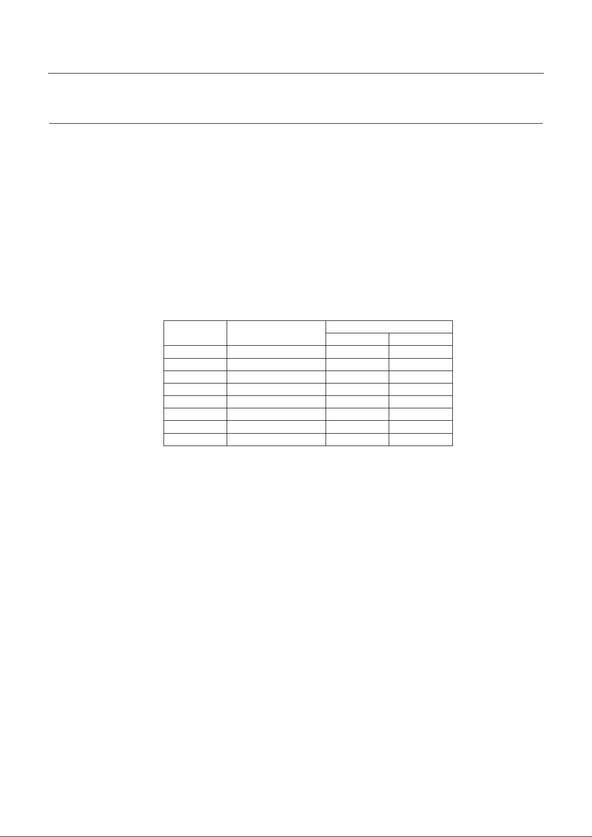
CBM-253 User’s Manual
ESC c 4 n
[Name] Selection of the effective paper end detector for stopping the printing
[Code] <1B>H <63>H <34>H <n>
[Defined range] 0 ≤ n ≤ 255
[Function] Selects which of the paper end detector conditi ons will be used for the paper end signal
output.
Each bit of n will have the meanings shown in the table below.
Bit Function
0 Journal near-end Disabled Enabled
1 Not defined
2 Not defined
3 Not defined
4 Not defined
5 Not defined
6 Not defined
7 Not defined
Value
0 1
In this printer, only one type of paper near-end detector can be selected for the paper end
detection, and only the lowest bit of n will be effective.
[Items requiring c aution ]
When the printing stopping is set to enabled, the printing stopping position will be the
position set by the DSW1-5 and DSW1-6 switches. After the printing has been stopped,
the printer will change to th e o ff-line condition.
[Initial value] n = 0
64
CITIZEN
Page 77

CBM-253 User’s Manual
[Program example]
LPRINT CHR$ (&H1B) + "c4" + CHR$ (0) ;
LPRINT CHR$ (&H1B) + "c4" + CHR$ (1) ;
Situation in which the printing has been
stopped by the paper end detector.
Situation in which the printing has been
stopped by the paper near-end detector.
ESC c 5 n
[Name] Enabling/disabling of the panel switch
[Code] <1B>H <63>H <35>H <n>
[Defined range] 0 ≤ n ≤ 255
[Function] Changes the LF switch between enabled and disabled.
• Only the lowest bit of n will be effective.
When n = <*******0>B, the LF switch will be enabled.
When n = <*******1>B, t h e LF sw i t c h will be disabled.
[Items requiring c aution ]
When the panel switch has been disabled using this command, the LF switch will not be
effective. Accordingly, it will not be possible to execute line f eeding by operation of the
LF switch.
[Initial value] n = 0
[Program example]
LPRINT CHR$(&H1B) + "c5" + CHR$ (0) ;
LPRINT CHR$(&H1B) + "c5" + CHR$ (1) ;
Situation in which the LF switch
operation is valid.
Situation in which the LF switch
operation is invalid.
65
CITIZEN
Page 78
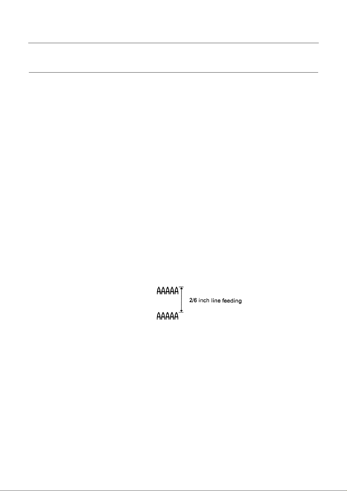
ESC d n
[Name] Printing. and line feeding of n lines
[Code] <1B>H <64>H <n>
[Defined range] 0 ≤ n ≤ 255
[Function]
Prints the data in the print buffer, and carries out a n -line portion of line feeding.
The next printing start position will be at the head of t he line. The settin g amount will not
remain after this operation has been carried out.
When label printing has been selected, i f the specifie d paper feeding a mount exceeds t he
lab e l length , the lin e feeding w il l be car r i ed o ut up to a pos ition a t the top of the following
CBM-253 User’s Manual
label. Because the printing will be accompanied by line feeding, even if printing is carr ied
out when a smaller value than the line feeding amount of 1 line has been set, line feeding
of more than the set amount may be carried out due to the printing operation.
[Initial value] Not defined.
[Program example] [Printing result]
LPRINT "AAAAA" ;
LPRINT CHR$(&H1B) + "d" + CHR$(2) ;
LPRINT "AAAAA" + CHR$ (&HA) ;
66
CITIZEN
Page 79

CBM-253 User’s Manual
ESC i
[Name] Fu ll c utting
[Code] <1B>H <69>H
[Function] When the thermal paper has been selected. this command executes a full cut of the
printing paper. When label paper has been selected, line feeding of the label will be
carried out up to t he cutting position (between the labels ), and then the lab el will be cu t
and ejected by the autocutter.
After ejection of the label, paper feeding will be carried out in the reverse direction to
mo ve to the top of th e n ext label.
[Items requiring c aution ]
This com mand w ill on ly be e ff ecti ve when input at the h ead of the line.
When thermal paper has been selected, make sure to feed the paper over 18mm before
cut t i ng t he p aper. Because charac ters right after printing are left inside of the cutter.
[Program example] [Printing result]
LPRINT "AAAAA" ;
LPRINT CHR$(&H1B) + "J" ;
LPRINT CHR$ (150) ;
LPRINT CHR$ (&H1B) + " i" ;
LPRINT "AAAAA" ;
LPRINT CHR$(&H1B) + "J" ;
LPRINT CHR$ (150) ;
LPRINT CHR$ (&H1B) + " i" ;
67
CITIZEN
Page 80

CBM-253 User’s Manual
ESC p m n1 n2
[Name] Specified pulse generation
[Code] <1B>H <70>H <m> <n1> <n2>
[Defined ranges] m= 0, 1
0 ≤ n1 ≤ n2 ≤ 255
[Function] Outputs the signals specified by nl and n2 to the connector pin m. The types of m pins are
according to th e table below.
m Connector pin
0 Drawer kick No. 2 pin (Drawer kick-out terminal 1)
1 Drawer kick No. 5 pin (Drawer kick-out terminal 2)
The ON time w ill be n 1 × 2ms, and the OFF time will be n 2 × 2ms.
[Items requiring c aution ]
If m is outside the defined range, n1 and n2 will be rejected for reading and the signal will
not output.
It is essential that the driving duty of the drawer should be within t h e fo l lo w in g rang e.
(ON time/(ON time + OFF time)) ≤ 0.2
(The OFF time should be at least 4 times more than the ON time.)
[Initial values] None of th e v alue s of m, n1 and n2 are defined.
[Program example]
LPRINT CHR$(&H1B) + "p"
LPRINT CHR$ (0) ; .....................Selection of the No. 2 pin
LPRINT CHR$ (5) ; .....................The ON time is set to 10ms
LPRINT CHR$ (50) ;....................The OFF time is set to 100ms
68
CITIZEN
Page 81

CBM-253 User’s Manual
ESC t n
[Name] Selection of the character code table
[Code] <1B>H <74>H <n>
[Defined range] 0 ≤ n ≤ 1
[Function] Selects page n of the character code tables. The character code table will be selected
according to the value of n.
n Characte r code page
0 Page 0(IBM character #2)
[Initial value] n = 0
[Reference] See the character code tables.
[Program example] [Printing result]
LPRINT CHR$(&H1B) + "t"+ CHR$(0) ;
LPRINT "n = 0" ;
FOR C=&HB1 T0 &HB5
LPRINT CHR$(C) ;
NEXT C
LPRINT CHR$ (&HA) ;
LPRINT CHR$(&H1B) + "t"+ CHR$(1) ;
LPRINT "n = 1 " ;
FOR C=&HB1 TO &HB5
LPRINT CHR$(C) ;
NEXT C
LPRINT CHR$ (&HA) ;
69
CITIZEN
Page 82

ESC v
[Name] Sending of the printer status (only Serial interface)
[Code] <1B>H <76>H
[Function] Sends the status of the printer at the current point of time.
[Items requiring c aution ]
The status that is sent will be 1 byte of data, and the contents will be as shown in the table
below. When the control is set to DTR/DSR, 1 byte only should be sent after confirming
that the host is in the receiving possible co ndition (the DSR signal is at 'space'). Further,
when the control is set to XON/XOFF, one byte only should be sent without confirming
the DSR signal condition.
CBM-253 User’s Manual
When the control is set to DTR/DSR and the host is in the receiving not possible
condition (the DSR signal is at 'mark'), wait until the DSR signal is in the receiving
possible condition. In the paper end (paper near-end) condition, there may be instances in
which receiving of this command may not be possible due to the BUSY condition.
This command w ill only be effective in serial interface printers .
Bit Function 0 1
0 Paper near-end Paper present No paper
1 Not defined
2 Paper end Paper present No paper
3 Not defined
4 Not used Fixed at 0
5 Not defined
6 Not defined
7 Not defined
70
CITIZEN
Page 83

[Program example]
OPEN "COM1 :N81NN" AS #1
PRINT #1,CHR$ (&H1B) + "v" ;
A$ = INPUT$(1,#1)
CLOSE #1
ESC u n
[Name] Sending of the peripheral equipment status (Only serial interface)
[Code] <1B>H <75>H <n>
[Defined range] n = 0
CBM-253 User’s Manual
[Function] Send the status of connector pin 3 at the current point of time. The types of n are
according to th e table below.
n
0
Connector pin
Drawer kick connector pin No. 3 (Drawer open/close detection terminal).
[Item requiring cautio n ]
The status that is sent will be 1 byte of data, and the contents will be as shown in the table
below. When there is no equip ment connected to t he con nector, bit 0 of n will a lways b e
'1'.
When the control is set to DTR/DSR, 1 byte only should be sent after confirming that the
host is in the receiving possible condition (the DSR signal is at 'space'). Further, when the
control is set to XON/XOFF, one byte only should be sent without confirming the DSR
signal condition.
When the control is set to DTR/DSR and the host is in the receiving not possible
condition (the DSR signal is at 'mark'), wait until the DSR signal is in the receiving
possible condition.
71
CITIZEN
Page 84

This command w ill only be effective in serial interface printers .
[Initial value] Not defined
[Program example]
OPEN "COM1:N81NN" AS #1
Bit Function
Value
0 1
0 Level of pin No. 3 'L' 'H'
1 Not defined
2 Not defined
3 Not defined
4 Not used Fixed at 0
5 Not defined
6 Not defined
7 Not defined
CBM-253 User’s Manual
PRINT #1,CHR$(&H1B) + "u" + CHR$(0) ;
A$ = INPUT$(1,#1)
CLOSE #1
ESC { n
[Name] Specifying/releasing of inverted printing
[Code] <1B>H <7B>H <n>
[Defined range] 0 ≤ n ≤ 255
[Function] Specifies and releases the inverted printing.
• Only the lowest bit of n will be effective.
n = <*******1>B Specifies inv erted printing
n = <*******0>B Rele ase s i nv ert e d prin tin g
72
CITIZEN
Page 85

[Items requiring caution]
Inverted printing is the printing of the line rotated through 180°. This command will only
be effective when it is input at the head of the line.
[Initial value] n = 0
[Program example]
LPRINT CHR$ (&H1B) + "l" + CHR$ (0) ;
LPRINT "AAAAA" + CHR$ (&HA) ;
LPRINT "BBBBB" + CHR$ ( & HA ) ;
LPRINT CHR$(&H1B) + " l" + CHR$(1) ;
LPRINT "AAAAA" + CHR$(&HA) ;
LPRINT "BBBBB" + CHR$ ( & HA ) ;
CBM-253 User’s Manual
[Print i n g re s u l t]
ESC $ n1 n2
[Name] Spec ify in g of absolute positions
[Code] <1B>H <24>H <n1><n2>
[Defined ranges] 0 ≤ n1 ≤ 255
0 ≤ n2 ≤ 1
[Function] Specifies the printing starting position as a number of dots (1/203 inch units) from the
head of the line.
The number of dots is divided by 256, with the quotient becoming n2 and the remainder
becoming n1. Accordingly, the printing starting position will be n1 + n2 × 256 dots from
the head of the line.
73
CITIZEN
Page 86

The num ber of the dots can be specified is as follows.
447 dot (Thermal paper)
423 dot (Thermal label paper)
[Items requiring c aution ]
Specifications that exceed the end of the line will be disregarded.
When underlining has been specified. the underlining will not be applied to t he moved
portion.
[Initial value] Not defined
[Reference] ESC ¥
CBM-253 User’s Manual
[Program example] [Printing result]
LPRINT CHR$ (&H1B) + "$" ;
LPRINT CHR$ (0) + CHR$ (0) + "A" ;
LPRINT CHR$ (&H1B) + "$" ;
LPRINT CHR$ (50) + CHR$ (0) + "B" ;
LPRINT CHR$ (&H1B) + "$" ;
LPRINT CHR$(0) + CHR$(1) + "C";
LPRINT CHR$ (&HA) ;
LPRINT CHR$(&H1B) + "$";
LPRINT CH R$ (100) + CHR$(0) + "A" ;
LPRINT CHR$ (&H1B) + "¥" ;
LPRINT CHR$ (&HC2) + CHR$ (&HFF) + "B" ;
LPRINT CHR$ (&HA) ;
74
CITIZEN
Page 87

CBM-253 User’s Manual
ESC ¥ n1 n2
[Name] Specifying of relative positions
[Code] <1B>H <5C>H <n1><n2>
[Defined range] 0 ≤ n1 ≤ 255
0 ≤ n2 ≤ 255
[Function] Specifies the printing starting position as a number of dots (1/203 inch units) from the
curr e nt p os iti on. The ri g ht di r e c t ion s h o ul d b e plus a n d the l e ft direc t i o n s h o uld be mi nus.
When specifying N dots in the minus direction, the specifying should be carried out using
the complement of N.
-N dots = 65536 – N
The number of dots should be divided by 256, with the quotient becoming n2 and the
reminder becoming n1.
[Items requiring c aution ]
Specifications that exceed the beginning or the end of the line will be disregarded. When
underlining has specified, the underlining will not be applied to the mov ed po rtion.
[Initial value] Not defined
[Reference] ESC $
[Program example] [Printing result]
Refer to th e p rog ram examp le and th e prin ti n g resu lt fo r ESC $ on page 74.
75
CITIZEN
Page 88

CBM-253 User’s Manual
GS FF
[Name] Printing, and label ejection
[Code] <1D>H <0C>H
[Function] Prints the data in the print buffer, and carries out the cutting and ejectin g o f the label.
• Line feeding of the label will be carried out up to the cutting position (between the
labels), then the label will be cut and ejected using th e au to-cutter.
• After ej ection o f the la bel, pa per fee ding wil l be ca rried o ut in the r everse directi on t o
mo ve to the top of th e n ext label.
• After setting the top of the next label, the alarm LED will flash, and the printer will wait
until the LF switch is pressed.
[Items requiring c aution ]
• After confirming that the alarm LED is flashing. press the LF switch one time.
• This com mand will on ly be e ff ect iv e when label printing has been selected.
• After sending a one-label portion of printing data. it is essential to send the <FF>
command or <GS FF> command.
[Reference] FF
[Program example] [Printing result]
LPRINT "LABEL 1" ;
LPRINT CHR$ (&H1D) + CHR$(&HC) ;
76
CITIZEN
Page 89

CBM-253 User’s Manual
GS k n [d]k NUL
[Name] Bar code print ing
[Code] <1D>H <6B>H <n> [<d>] k <00>H
[Defined range] 0 ≤ n ≤ 7
[Function] Selects the bar code type, and carries out bar code printing. The next printing starting
position will be taken as the head of the line.
The bar code systems shown in the table below will be selected according to the n value.
d indicates the characters for printing. and k shows the number of characters for printing.
n Bar c ode type
0 UPC-A
1 UPC-E
2 JAN-13 (EAN)
3 JAN-8 (EAN)
4 CODE 39
5 ITF
6 CODABAR (NW-7)
7 CODE 128
[Items requiring c aution ]
When there is data present in the print buffer, this command will be disregarded.
Regardless of the currently set line feeding amount, only the line feedi ng required for the
bar code printin g w ill be carried out.
In each of the bar code type, when the character code d contains characters that cannot be
printed, the bar code up to this point will be printed and the subsequent data will be
processed as ordinary data.
77
CITIZEN
Page 90

CBM-253 User’s Manual
When a bar code type has been selected in which the number of printing characters is
fixed, the number of characters k must correspond to this fixed number of printing
characters.
When the horizontal direction exceeds a one line length. the part in excess will not be
printed.
[Initial values] Not defined
[Explanation of each bar code]
<Refer to print sample o n pa ge 6.>
UPC-A This is a fixed-length bar code that is composed of 12 figures of numerals only. 11 of the
figures of the number should be input using software by the host unit or application, and
the 12th figure is a chec k digit that will be auto matically calculated i nside the printer, If
the 12th figure of the number is also sent from the host unit, the complete bar code will be
printed as it is.
UPC-E This is a fixed-length bar code that is composed of 8 figures of numerals only. The first
number system character is fixed as '0'. The 12-figure number should be input using
software by the host unit or application, and this number will be compressed to a 8-fig ure
number with a check digit before being printed. Although the 12th figure check digit will
be automatically calculated inside the printer if the 12th figure of the number is also sent
the host unit, to complete bar code as it is will be compressed to the 8-figure number and
printed.
JAN- 13 (EAN) This is a fixed-length bar code that is compressed of 13 figures of numerical values only.
12 of the figures of the number should be input using software by the host unit or
application, and the 13th figure is a check digit that will be automatically calculated
inside the printer. If the 13th figure of the number is also sent from the host unit, the
com plete bar code will be printed as it is.
78
CITIZEN
Page 91

CBM-253 User’s Manual
JAN-8 (EAN) This is a fixed-length bar code that is composed of 8 figures of numerical values only. 7
of the figures of the number should be input using software by the host unit or application,
and the 8th figure is a check di git that will be aut omatically calculate d inside the printer.
If the 8th figure of the number is also sent from the host unit, the complete bar code will
be printed as it is.
CODE 39 This is a variable-length bar code that is composed of alphabet capital letters and
numerals. The start and stop code ' * ' marks are attached automatically by the printer.
Characters that can be used are spaces, '$%*+-./0123456789', and the alphabet capital
letters.
ITF This is an even-numbered variable-length bar code that is composed of numerals only. If
an odd number figure code is transmitted, the last figure will be discarded in order to
make an even numbered figure before printing.
CODABAR This is a variable-length bar code that is composed of alphanumeric characters.
Characters whic h may be u sed are '0123456789abcd $+-./: ' .
Start and stop cod es will be required, which can be any one of 'abcd' .
CODE 128 • This is a variable-length bar code that is composed of any of the 128 characters of
ASCII code. Code sub-sets A, B, and C are supported by this printer, and the code subset at the start of printing should be selected by setting 1 character of any of 'ABC' at the
head of the transmission code. If no 'ABC' character has been set at the head of the code,
the code sub-set B will be selected.
• Code sub-set A is a ba r code made up of the standard capital letters of the alphabet,
numerals, symbols, and special codes.
• Co de sub- set B is a bar code made up of the sta ndar d capita l and s mall l etter s of th e
alphabet, numerals, control codes, and special characters.
79
CITIZEN
Page 92

CBM-253 User’s Manual
• Code sub-set C is a bar code made up of special characters together with the 100
numbers between 00 and 99.
• After inputting the number of figures, a check digit will be automatically calculated
inside the printer and added to the figures, and then printing will be carried out.
• Processing of special characters
Characters having an ASCII code nu mber of 96 or greater will be recognized as special
characters. The switching characters required to input these characters are given bel ow.
ASCII code
Switching
character
Sub-set
code A
Sub-set
code B
Sub-set
code C
96 80h FNC3 FNC 3 N/A
97 81h FNC 2 FNC 2 N/A
98 82h SHIFT SHIFT N/A
99 83h CODE C CODE C N/A
100 84h CODE B FNC 4 CODE B
101 85h FNC 4 CODE A CODE A
102 86h FNC 1 FNC 1 FNC 1
The foll owing shows a n example of the s election of t he code sub-se t using this s pecial
charact er method.
<Code su b-set selection>
Initial selection: 1 character input of any of 'A, B or C'.
Switching during operation: 1 character input of any of the 82h~85h characters.
e.g. In a situation where first the bar code 'TEST' is to be printed using code sub-set B, and
then t he bar code '123' is to be printed using code sub -set A.
Input codes: B TE ST < 85 h> 1 23
Bar code data: <CODE B>TEST<CODE A>123
80
CITIZEN
Page 93

[Program example] [Printing result]
LPRINT CHR$(&H1D) + "H" + CHR$ (2) ;
LPRINT CHR$ (&H1D) + "k" ;
LPRINT CHR$(4) ;
LPRINT "123" + CHR$ (0) ;
CBM-253 User’s Manual
81
CITIZEN
Page 94

GS w n
[Name] Selection of bar code horizontal size (enlargement rate)
[Code] <1D>H <77>H <n>
[Defined range] 2 ≤ n ≤ 4
[Function] Selects the bar code horizontal size.
n indicates the number of dots of the fine element width.
[Initial value] n = 3
[Program example]
CBM-253 User’s Manual
LPRINT CHR$(&H1D) + "h" + CHR$ (30) ;
LPRINT CHR$(&H1D) + "w" + CHR$(2) ;
GOSUB BC
LPRINT CHR$(&H1D) + "h" + CHR$ (50) ;
LPRINT CHR$(&H1D) + "w" + CHR$ (3) ;
GOSUB BC
LPRINT CHR$(&H1D) + "h" + CHR$(80) ;
LPRINT CHR$(&H1D) + "w" + CHR$(4) ;
GOSUB BC
END
BC :
LPRINT CHR$(&H1D) + "k" : LPRINT CHR$ (4) ;
LPRINT "12" + CHR$(0) ;
RETURN
[Print i n g re s u l t]
82
CITIZEN
Page 95

CBM-253 User’s Manual
GS h n
[Name] Selection of bar code height
[Code] <1D>H <68>H <n>
[Defined range] 1 ≤ n ≤ 255
[Functio n] Selects the bar code height. n indicates the number of dots in the vertical direction.
[Initial value] n = 170
[Program example]
Refer to the pro g ram exam p l e and th e prin ti n g resu lt for GS w on p a ge 82.
GS H n
[Name] Selection of visual code printing position
[Code] <1D>H <48>H <n>
[Defined range] 0 ≤ n ≤ 3
[Function] Selects the printing position of the visual code when printing the bar code. The printing
positio n s that may b e sel ect ed acc o rdin g to th e n val u e are shown in the table below.
n Printing position
0 Not printed
1 Above the bar code
2 Below the bar code
3 Both above and below the bar code
The visual code is the showing of the bar code in characters so that the bar code can be
read visually.
83
CITIZEN
Page 96
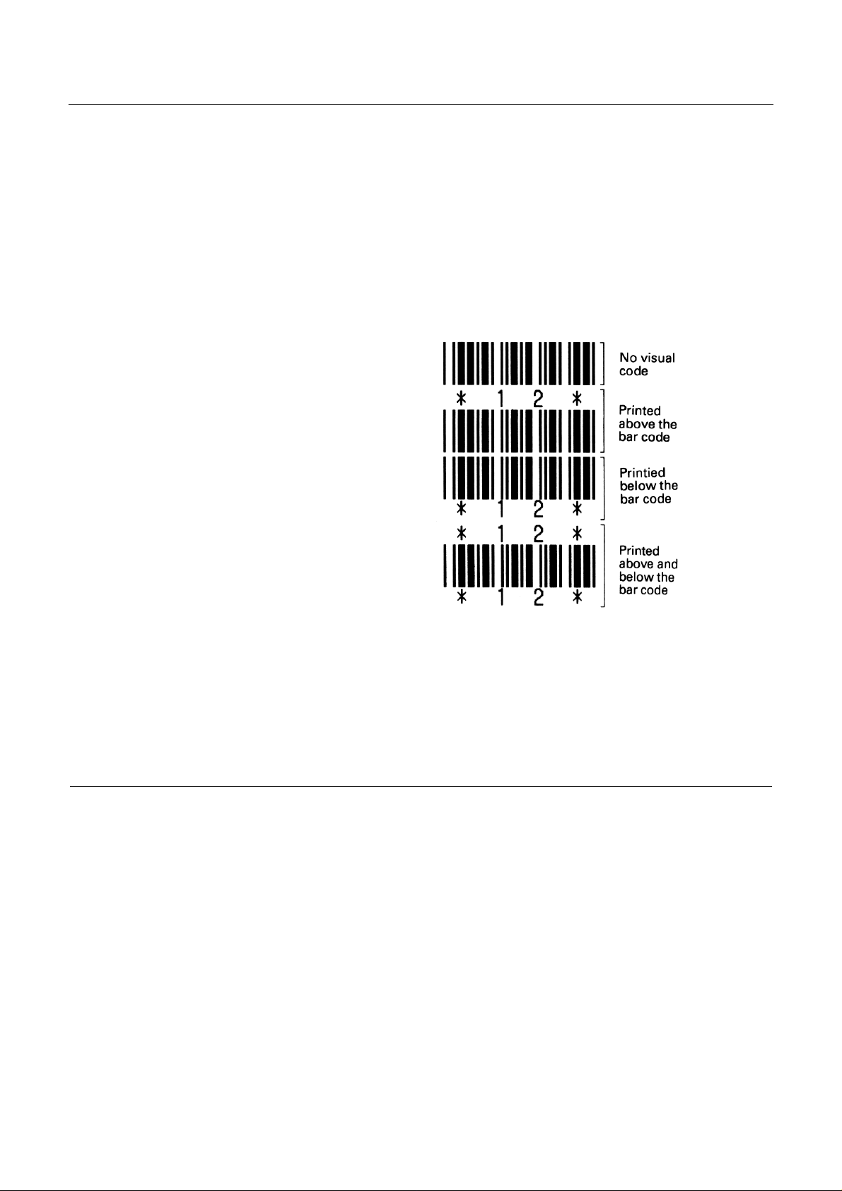
[Items requiring c autio n] The visual code w ill be p rin te d using the font selected using GS f.
[Initial value] n = 0
[Reference] GS f
[Program example] [Printing result]
LPRINT CHR$ (&H1B) + "3" + CHR$(5) ;
LPRINT CHR$ (&H1D) + "h" + CHR$ (50) ;
LPRINT CHR$ (&H1D) + "H" + CHR$ (0) ;
GOSUB BC
LPRINT CHR$ (&H1D) + "H" + CHR$ (1) ;
GOSUB BC
LPRINT CHR$ (&H1D) + "H" + CHR$ (2) ;
CBM-253 User’s Manual
GOSUB BC
LPRINT CHR$(&H1D) + "H" + CHR$ (3) ;
GOSUB BC
END
BC :
LPRINT CHR$ (&H1D) + "k" ;
LPRINT CHR$ (4) ; LPRINT "12" + CHR$(0) ;
LPRINT CHR$ (&HA) ;
RETURN
GS f n
[Name] Selection of visual code font
[Code] <1D>H <66>H <n>
[Defined range] n = 0, 1
84
CITIZEN
Page 97

CBM-253 User’s Manual
[Function] Selects the font for the visual code when printing the bar c ode.
The fonts that can be selected according to the n value are shown in the table below.
n Font
0 Font 1
1 Font 2
The visual code is the showing of the bar code in characters so that the bar code can be
read visually.
[Items requiring c aution ]
The visu al cod e w ill be p rinte d at the position specified using GS H.
[Initial value] n = 0
[Reference] GS H
[Program example] [Printing result]
LPRINT CHR$(&H1D) + "h" + CHR$(50) ;
LPRINT CHR$ (&H1D) + "H" + CHR$ (2) :
LPRINT CHR$ (&H1D) + "f" + CHR$ (0) ;
GOSUB BC
LPRINT CHR$ (&H1D) + "f" + CHR$ (1)
GOSUB BC
END
BC :
LPRINT CHR$(&H1D) + "k" ;
LPRINT CHR$ (4) ;
LPRINT "123" + CHR$ (0) ;
LPRINT CHR$ (&HA) ;
RETURN
85
CITIZEN
Page 98

GS c
[Name] Printing of counter
[Code] <1D>H <63>H
[Function] Prints the consecutive number counter.
• Sets the current numerical value of the counter in the print buffer as printing data (line
of characters), and then counts up or counts down the counter depending on the
counting mode that has been set.
[Items requiring caution]
• The format of the data when it is set in the print buffer will be according to the GS C 0
command.
CBM-253 User’s Manual
• The counting mode will be according to the GS C 1 or GS C ; commands.
When counting up:
• If the counter value set using this command is outside the operation range of the counter
set using the GS C 1 or GS C ; commands the counter will be forcibly changed to the
minimum value by the execution of GS c.
When counting down:
• If the counter value set using this command is outside the operation range of the counter
set using the GS C 1 or GS C ; commands, the counter will be forc ibly changed to the
maximum value by the execution of GS c.
86
CITIZEN
Page 99

[Program example]
CBM-253 User’s Manual
LPRINT CHR$ (&H1D) + "C0" ;
LPRINT CHR$(0) + CHR$(0) ;
GOSUB CNT
LPRINT CHR$ (&H1D) + "C0" ;
LPRINT CHR$ (1) + CHR$ (0) ;
GOSUB CNT
LPRINT CHR$ (&H1D) + "C0" ;
LPRINT CHR$ (3) + CHR$ (0) :
GOSUB CNT
LPRINT CHR$ (&H1D) + "C0" ;
LPRINT CHR$(3) + CHR$(1) ;
GOSUB CNT
LPRINT CHR$(&H1D) + "C0" ;
LPRINT CHR$(3) + CHR$(2) ;
GOSUB CNT
END
CNT :
FOR I=1 TO 5
LPRINT CHR$(&H1D) + "c" ;
NEXT I
LPRINT CHR$ (&HA) ;
RETURN
[Print i n g re s u l t]
GS C O m n
[Name] Setting of the numbering printing mode
[Code] <1D>H <43>H <30>H <m> <n>
[Defined ranges] 0 ≤ m ≤ 5
0 ≤ n ≤ 2
87
CITIZEN
Page 100

CBM-253 User’s Manual
[Function] Sets the printing mode of the numbering (consecutive numbering counter).
• m indicates the number of figures for printing.
m = 0 Only the actual number of figures are printed. In this case, n will have no
meaning.
m = 1~5 This is the maximum number of figures for printing.
If the number of figures of the counter value is greater than number of
figures s pecified b y this command, t he last m fi gures of the c ounter value
will be printed .
• n specifies the printing position inside the number of figures for printing.
n = 0 Printing will be carried out from the right end. When the value has less than
the specified number of figures, the empty places will become spaces.
n = 1 Printing will be carried out from the right end. When the value has less than
the specified nu mber of figures. the empty places will become 0.
n = 2 Printing will be ca rried out from the left end. Spaces will be a dded to the
right side of the value in order to make up the specified numbe r of figures.
[Items requiring c aution ]
If either m or n is outside the defined range, the setting will be invalid
[Initial value] m = 0
[Reference] GS C 1, GS C 2, GS c, GS C ;
[Program example] [Printing result]
Refer to the program example an d the printing result f or GS c on page 87.
88
CITIZEN
 Loading...