


LINE THERMAL PRINTER
MODEL CBM-290/291
User’s Manual

CBM-290/291 User’s Manual
Declaration of Conformity
This printer conforms to the following Standards:
Low Voltage Directive 73/23/EEC, 93/68/EEC and the EMC Directive 89/336/EEC,
92/31/EEC, 93/68/EEC.
LVD : EN60950
EMC : EN55022
Class A
EN61000-3-2
EN61000-3-3
EN55024
This declaration is applied only for 230V model.
Warning: This is a Class A products. In a domestic environment this product may cause radio intereference
in which case the user may be required to take adequate measures.
CITIZEN is a registered trade mark of CITIZEN WATCH CO., LTD., Japan
CITIZEN es una marca registrada de CITIZEN WATCH CO., LTD., Japón
CITIZEN

CBM-290/291 User’s Manual
IMPORTANT SAFETY INSTRUCTIONS
• Read all of these instructions and save them for later reference.
• Follow all warnings and instructions marked on the product.
• Unplug this product from the wall outlet before cleaning. Do not use liquid or aerosol cleaners. Use a
damp cloth for cleaning.
• Do not use this product near water.
• Do not place this product on an unstable cart, stand or table. The product may fall, causing serious
damage to the product.
• Slots and openings on the cabinet and the back or bottom are provided for ventilation.
To ensure reliable operation of the product and to protect it from overheating, do not block or cover
these openings. The openings should never be blocked by placing the product on a bed, sofa, rug of
other similar surface. This product should never be placed near or over a radiator or heat register. This
product should never be placed near or over a radiator or heat register. This product should not be
placed in a built-in installation unless proper ventilation is provided.
• This product should be operated from the type of power source indicated on the marking label. If you re
not sure of the type of power available, consult your dealer or local power company.
• Do not allow anything to rest on the power cord. Do not locate this product where the cord will be
walked on.
• If an extension cord is used with this product, make sure that the total of the ampere ratings on the
products plugged into the extension cord do not exceed the extension cord ampere rating. Also, make
sure that the total of all products plugged into the wall outlet does not exceed 15 amperes.
• Never push objects of any kind into this product through cabinet slots as they may touch dangerous
voltage points or short out parts that could result in a risk of fire or electric shock. Never spill liquid of
any kind on the product.
• Except as explained elsewhere in this manual, don’t attempt to service this product by yourself.
Opening and removing those covers that are marked “Do Not Remove” may expose you to dangerous
voltage points or other risks. Refer all servicing on those compartments to service personnel.
• Unplug this product from the wall outlet and refer servicing to qualified service personnel under the
following conditions:
A. When the power cord or plug is damaged or frayed.
B. If liquid has been spilled into the product.
C. If the product has been exposed to rain or water.
D. If the product does not operate normally when the operating instructions are followed. Adjust only
those controls that are covered be the operating instructions since improper adjustment of other
controls may result in damage and will often require extensive work by a qualified technician to
restore the product to normal operation.
E. If the product has been dropped or the cabinet has been damaged.
F. If the product exhibits a distinct change in performance, indicating a need for service.
• Please keep the poly bag which this equipment is packed in away from children or throw it away to
prevent children from putting it on. Putting it on may cause suffocation to them.
CITIZEN

CBM-290/291 User’s Manual
WICHTIGE SICHERHEITSANWEISUNGEN
• Lesen Sie die nachfolgenden Anweisungen sorgfältig durch und bewahren Sie sie auf.
• Befolgen Sie alle auf dem Drucker vermerkten Hinweise und Anweisungen. Vor dem Reinigen
grundsätzlich Stecker aus der Steckdose ziehen. Keine Flüssigkeiten oder Aerosolreiniger benutzen.
Nut mit einem feuchten Tuch abwischen.
• Der Drucker darf nicht in der Nähe von Wasser aufgestellt werden.
• Drucker nicht auf einem unstabilen Wagen, Stand oder Tisch aufstellen. Der Drucker könnte
herunterfallen und dabel beschädigt werden.
• Schlitze und Öffnungen im Gehäuse, in der Rückwand und im Boden dienen der Belüftung. Sie dürfen
keinesfalls zugedeckt oder blockiert werden, da sich der Drucker sonst überhitzt. Drucker nicht auf
ein Bett, Sofa, Teppich oder dergleichen stellen. Drucker nicht in der Nähe eines Heizkörpers
aufstellen. Drucker darf nicht eingebaut werden, falls nicht für ausreichende Belüftung gesorgt ist.
• Drucker nur mit der auf dem Typschild angegebenen Spannung betreiben. Wenn Sie sich nicht sicher
sind, fragen Sie ihren Händler oder ihr zuständiges Elektrizitätswerk.
• Nichts auf das Stromanschlußkabel stellen. Kabel muß so verlegt werden, daß man nicht darauftreten
kann.
• Ein etwaiges Verlängerungskabel muß der Stromstärke aller daran angeschlossenen Geräte entsprechen.
• Keine Gegenstände in die Gehäuseschlitze schieben.
• Drucker darf nur da gewartet werden, wo im Handbuch angegeben, Öffnen und. Abnehmen von
Abdeckungen, die mit “Do not remove” gekennzeichenet sind, könnte gefährliche spannungführende
Stellen oder sonstige Gefahrenpunkte freilegen. Die Wartung solcher Stellen darf grundsätzlich nur von
besonders ausgebildetem Fachpersonal vorgenommen werden.
A. Wenn das Stromanschlußkabel oder der Stecker beschädigt oder durch-gescheuert ist.
B. Wenn Flüssigkeit auf dem Drucker verschüttet wurde.
C. Wenn der Drucker im Regen gestanden hat oder Wasserdarauf verschüttet wurde.
D. Wenn der Drucker trotz genauer Befolgung der Betriebsvorschriften nicht richtig arbeitet. Nur die in
der Bedienungsanleitung angegebenen Einstellungen vornehmen. Ein Verstellen anderer
Bedienungselemente könnte den Drucker beschädigen und macht umständliche Arbeiten eines
qualifizierten Technikers erforderlich, um den Drucker Wieder auf den normalen Betrieb
einzustellen.
E. Wenn der Drucker heruntergefallen ist oder das Gehäuse beschädigt wurde.
F.Wenn der Drucker in seiner Leistung nachläßt.
• Bitte halten Sie den Kunststoffbeutel, in den die Ware verpackt ist, von Kindern entfernt, oder werfen
Sie ihn weg, damit er nicht in die Hande von Kindern gerät. Das Überstülpen des Beutels kann zum
Ersticken führen.
Lärmemission kleiner 70dBA
CITIZEN

CBM-290/291 User’s Manual
IMPORTANT:
installed and used in accordance with the instruction manual, may cause interference to radio
communications. It has been tested and found to comply with the limits for a Class A computing device
pursuant to Subpart J of Part 15 off FCC Rules, which are designed to provide reasonable protection
against such interference when operated in a commercial environment. Operation of this equipment in a
residential area is likely to cause interference, in which case the user at his own expense will be required to
take whatever measures may be necessary to correct the interference.
This equipment generates, uses, and can radiate radio frequency energy and if not
CAUTION: Use shielded cable for this equipment.
Sicherheitshinweis
Die Steckdose zum Anschluß dieses Druckers muß nahe dem Grät angebracht und leicht zugänglich sein.
For Uses in Canada
This digital apparatus does not exceed the class A limits for radio noise emissions from digital, apparatus,
as set out in the radio interference regulations of the Canadian department of communications.
Pour L’utilisateurs Canadiens
Cet appareil numérique ne dépasse pas les limites de carégorie a pour les émissions de bruit radio émanant
d’appareils numériques, tel que prévu dans les réglements sur l’interférence radio du départment Canadien
des communications.
CITIZEN

CBM-290/291 User’s Manual
<CAUTIONS>
1. Prior to using the equipment, be sure to read this User's Manual thoroughly. Please keep it handy for reference
whenever it may be needed.
2. The information contained herein may be changed without prior notice.
3. Reproduction of part or all of this User's Manual without permission is strictly prohibited.
4. Never service, disassemble, or repair parts that are not mentioned in this User's Manual.
5. Note that we will not be responsible for damages attributable to a user's incorrect operation/ handling or an
improper operating environment.
6. Operate the equipment only as described in this User's Manual; otherwise accidents or problemsmay result.
7. Data are basically temporary; they cannot be stored or saved permanently or for a long time. Please note that
we will not be responsible for damages or losses of profit resulting from losses of the data attributable to
accidents, repairs, tests, and so on.
8. If you have any questions or notice any clerical errors or omissions regarding the information in this manual,
please contact our office.
9. Please note that, notwithstanding Item 8 above, we will not be responsible for any effects resulting from
operation of the equipment.
This is an illustration mark used to alert your attention.
This is an illustration mark used to indicate such information as an instruction or the like.
CITIZEN

CBM-290/291 User’s Manual
WARNING
• Never handle the equipment in the following manners, as it may break, become out of order, or
overheat causing smoke and resulting in fire or electric shock.
• If you find any damage, problem, smoke, or abnormal odor/sound, turn off the power, disconnect the
power cable, and contact your dealer. Never repair the equipment on your own - it is very dangerous.
• Do not allow the equipment to receive a strong impact or shock, such as kicking, stomping, hitting,
dropping, and the like.
• Install the equipment in a well-ventilated place. Do not use it in such a manner that its ventilation port
will be blocked.
• Do not install the equipment in a place like a laboratory where chemical reactions are expected, or in a
place where salt or gases are contained in the air.
• Use only power of the specified voltage and current capacity.
• Do not connect/disconnect a power cord or a data cable, while holding the cable. Do not pull, install,
use, or carry the equipment in such a manner that force will be applied to the cables.
• Do not drop or insert any foreign substances, such as clips or pins, into the equipment.
• Do not put many loads on one electrical outlet.
• Do not spill any liquid or spray any chemical-containing liquid over the equipment. If any liquid is
spilled on it, turn off the power, disconnect the power cable and power cord from the plug socket, and
so on, and contact our dealer.
• Do not disassemble or remodel the equipment. Negligence of this may cause fire or electric shock.
• An equipment packing bag must be discarded or kept away from children. A child can suffocate if the
bag is placed over the head.
CITIZEN

CBM-290/291 User’s Manual
PRECAUTIONS FOR INSTALLATION
• Do not use or store the equipment in a place exposed to fire, moisture, or direct sunlight, or in a place
near a heater or a thermal device where the prescribed operating temperature and humidity are not met,
or in a place exposed to much oil, iron powder, or dust. The equipment may become out of order, emit
smoke, or catch fire.
• Do not install the equipment in a place like a laboratory where chemical reactions are expected, or in a
place where salt or gases are contained in the air. There is a danger of fire or electric shock.
• Firmly secure the equipment onto a flat and stable mounting panel free from vibrations and angled at 0°
to 90° in a well-ventilated place.
• Do not install or use the equipment in a place where its operation could be hindered.
• Do not place anything on the equipment, as it can lead to problems.
• Use accessory fittings and screws to secure the equipment. Tighten the screws firmly and properly.
Excessive tightening can result in problems or damage.
• Do not use the equipment near a radio or TV receiver . Do not share the power from a plug socket a
radio or TV receiver is connected to. It may cause a reception problem.
• Use only power of the specified voltage and current capacity. Be careful not to mistake polarity.
The equipment may become out of order, emit smoke, or catch fire.
• Confirm that a plug socket used for connection has sufficient capacity.
• Avoid composite wiring with a power cable or excessively extended wiring. Excessive electric current
may cause heat generation/ignition of the supply line or shut off the power. Do not step on a cable or
use the equipment with excessive force (tension, load) applied to it.
• Never connect a grounding cable to a gas pipe. There is a danger of explosion. When connecting or
disconnecting the grounding cable, be sure to disconnect the power plug from the plug socket.
• When disconnecting/reconnecting the cables, be sure to turn off the power, including the mating side.
• Connect a connector cable securely. If a reverse-polarity connection is made, internal elements may be
broken or a mating device may be adversely affected.
• Avoid routing a signal line too long or connecting to any noisy device, to protect against such effects as
data deformation due to noise.
• Use the equipment in an environment where there is a plug socket near the main body and you can
easily disconnect the power plug from it, to shut off the power.
• Keep the equipment in the printing-head-up state when transporting the equipment or when it will not
be used for a long time.
• When transporting the equipment, remove the rolled paper from it.
CITIZEN

CBM-290/291 User’s Manual
PRECAUTIONS FOR HANDLING
Do not handle the equipment in the following manners, because problems may result.
• Do not print without setting a roll of paper.
• Be careful not to drop foreign substances, such as clips, pins, and screws, into the main body.
• Do not spill any liquid or spray any chemical-containing liquid over the equipment.
• Do not stamp on, drop, hit, or give a strong shock to the equipment.
• Never use a pointed object, such as a pen, to operate the operation panel.
• Do not use Scotch tape to fasten paper together for continuous use.
• With the printing head down, never rotate the paper feed knob or force to pull the set roll of paper by
hand.
To Prevent Injury and Spreading of Damage
• Do not touch the printing part of the print head.
• When turning on the power, do not touch the moving parts, such as a cutter and gear inside the main body,
or electric parts.
• Be careful to avoid bodily injure or damaging other objects with an edge of sheet metal.
• Should any error occur while operating the equipment, stop it immediately and disconnect the power plug
from the plug socket.
• Should a problem occur, leave solving it to our serviceman. Do not disassemble the equipment on your
own.
• When opening/closing the panel, and so on, be careful not to catch your hand or finger on the equipment.
CITIZEN
CBM-290/291 User’s Manual
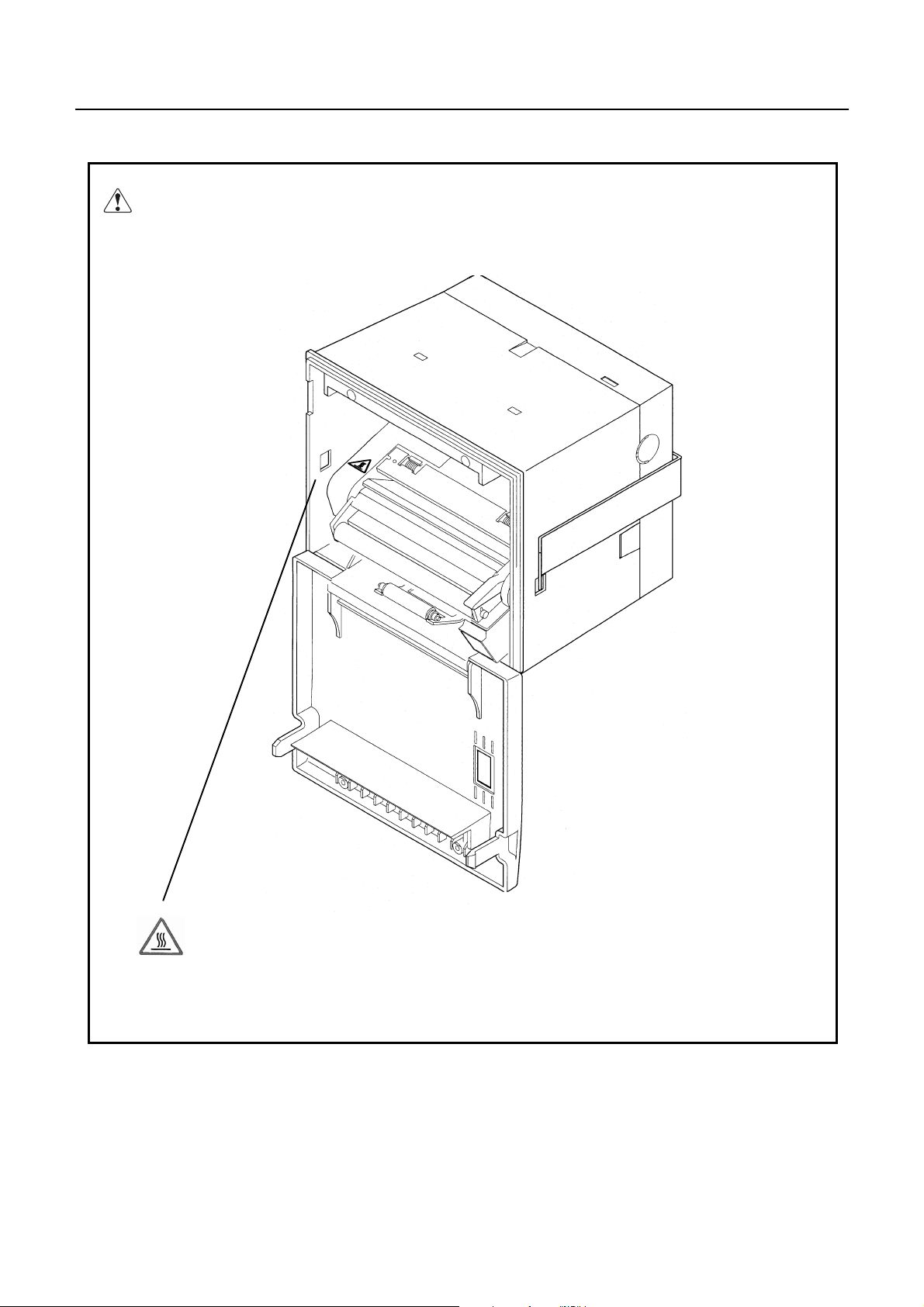
A caution label has been pasted to the position shown in the figure below. Read the precautions for
handling thoroughly, to operate the equipment correctly.
This label alerts you to the danger that
touching the printing head or motor can
cause a burn injury because they are
hot.
CITIZEN
CBM-290/291 User’s Manual
ORDINARY MAINTENANCE
1. Make sure to maintain the equipment afterswiching OFF the power.
2. When cleaning the platen of printer mechanism, wipe out the dirty portion by a cotton pud dipped
into ethyl alcohol.
3. When cleaning the surface of the main unit case, use soft cloth.
In case the dirty portion can not be cleared out by the soft cloth, use wet cloth squeezed thghtly .
Absolutely do not use thinners, trichlene, benzine or ketone group solvents, or chemical-impregnated
cleaning cloths.
4. In case the point head becomes dirty because of paper dust, clean it by using a soft brush.
CAUTION:
Do not carry out the maintenance right after printing, since print head and
moter are so hot.
CITIZEN

CBM-290/291 User’s Manual
CONTENTS
1. OUTLINE................................................................................................................................................................. 1
1.1 Features ................................................................................................................................................................ 1
1.2 Package................................................................................................................................................................. 1
2. BASIC SPECIFICATIONS .................................................................................................................................... 2
2.1 Model classifications............................................................................................................................................ 2
2.2 Specifications....................................................................................................................................................... 3
2.3. Specifications of Roll paper ................................................................................................................................ 4
2.3.1. Recommended paper..............................................................................................................................................4
2.3.2. Printing position .....................................................................................................................................................4
2.3.3. Position of printer head and auto cutter.................................................................................................................. 4
2.4 Specified Power Supply ....................................................................................................................................... 4
2.4 Specified Power Supply ....................................................................................................................................... 5
2.5 Outer appearances and parts name ....................................................................................................................... 5
2.5.1 Outer appearances and parts name..........................................................................................................................5
2.5.2 Explanation of each parts ........................................................................................................................................ 6
3. Operation.................................................................................................................................................................. 7
3.1 Rack mounting ..................................................................................................................................................... 7
3.2 Connecting a cable for power supply and interface.............................................................................................. 8
3.3 Opening/closing front cover ................................................................................................................................. 9
3.4 Paper feeding...................................................................................................................................................... 10
3.5 Auto paper loading function............................................................................................................................... 10
3.6 Setting roll paper ................................................................................................................................................ 10
3.7 Removing paper jam and canceling cutter lock.................................................................................................. 12
3.8 Self print function............................................................................................................................................... 13
3.9 PE and Mechanical alarm................................................................................................................................... 13
3.9.1 Paper end (PE).......................................................................................................................................................13
3.9.2 Mechanical alarm .................................................................................................................................................. 13
4. Dip switch setting................................................................................................................................................... 14
5. Connecting connector............................................................................................................................................ 15
5.1 Function of each connector pins......................................................................................................................... 15
5.2 Precautions......................................................................................................................................................... 16
6. Parallel Interface ................................................................................................................................................... 16
6.1 Specifications..................................................................................................................................................... 16
CITIZEN

CBM-290/291 User’s Manual
6.2 Explanation of input / output signals.................................................................................................................. 16
6.3 Electrical characteristics..................................................................................................................................... 17
6.4 Timing chart ....................................................................................................................................................... 18
6.5 Data receiving control ........................................................................................................................................ 18
6.6 Buffering ............................................................................................................................................................ 18
7. Serial Interface....................................................................................................................................................... 19
7.1 Specifications..................................................................................................................................................... 19
7.2 Explanation of Input / Output signals................................................................................................................. 20
7.2.1 Input / Output signals ............................................................................................................................................20
7.3 Date configuration.............................................................................................................................................. 21
7.4 Error detection.................................................................................................................................................... 21
7.5 Data receiving control ........................................................................................................................................ 22
7.6 Buffering ............................................................................................................................................................ 22
7.7 Electrical characteristics..................................................................................................................................... 22
9. Print Control Function.......................................................................................................................................... 24
9.1 Command Lit...................................................................................................................................................... 24
9.2 Command Details ............................................................................................................................................... 25
10. Character Table................................................................................................................................................... 42
10.1 International...................................................................................................................................................... 42
10.2 International Character Code Table.................................................................................................................. 43
Appendix 1. Block Diagram...................................................................................................................................... 44
Appendix 2. Outer Appearance................................................................................................................................ 45
CITIZEN

CBM-290/291 User’s Manual
1 OUTLINE
CBM-290 is a Line Thermal printer which can be equipped in a rack and is widely used for
various data communication, POS terminal and various measurement devices.
This printer can be used for various applications since abundant functions are incorporated. Prior
to actual use, please read this instruction manual carefully for your correct understanding.
1.1Features
1. Ultra small-sized rack mounting line thermal printer
2. High speed and quite printing
3. High reliability due to the long life of thermal print head and simple design
4. Serial(RS-232C) and Parallel(Centronics) interface are available by dip switch
5. Input buffer incorporated
6. Bar code printing(by special command)
7. Auto paper cutter is equipped(CBM-291 only)
8. User-defined character registration function (94 characters)
1.2 Package
Make sure to confirm the following components are contained in this package.
Printer main unit....................................................... 1 pc
Roll paper sample..................................................... 1 pc
A cable for power supply and interface.................... 1 pc
Rack mounting bracket............................................. 1 pc
Screw for mounting ..................................................2 pcs
Wire cramp............................................................... 1 pc
User’s manual........................................................... 1 pc
1
CITIZEN

2 BASIC SPECIFICATIONS
2.1Model classifications
CBM-290/291 User’s Manual
CBM - 290 −−−− 34 F −−−−
()
Model name
CBM-290 : No auto paper cutter
CBM-291 : Auto paper cutter equipped
Number of print columns
34:34columns(FontA)
Character set
F:International
Supplement code
None:Standardmodel
2
CITIZEN

CBM-290/291 User’s Manual
2.2 Specifications
ITEM CONTENTS
Printing method Line Thermal Dot Printing System
Printspeed 50mm/s(MAX)
Dot density 8 Dots / mm (Vertical/ Horizontal)
Number of columns Font A : 34 columns
Font B : 46 columns
Character size Font A : 1.25 mm × 3.00 mm (10 × 24 + 2 dot space)
Font B : 0.88 mm × 2.13 mm ( 7 × 17 +2 dot space)
Character type Alphanumeric, international characters
Bar code type UPC-A/E, JAN (EAN) 13 / 8 columns , ITF
CODE 39, CODE 128, CODABAR
Line pitch 4.23 mm (1/6 inch) (Selectable by command)
Paper Thermal Roll Paper Paper Width : 58 mm Roll Diameter : Ø50 mm or less
Interface Parallel (conforms to Centronics) or Serial (conforms to RS-232C)
(Selectable by dip switch)
Input buffer 4 K bytes
Paper end detection Equipped (Printer stops printing when roll paper runs out completely.)
Auto-Loading function Equipped (Printer automatically feeds paper when paper sensor detects paper
in paper inlet.)
International Character U.S.A., France, Germany, U.K., Denmark 1,2, Sweden, Italy,
Spain, Japan, Norway (Specified by command)
Auto paper cutter
(Only CBM-291)
Supply voltage 5V ± 5 % Stand-by : Aprrox.0.2A Printing : Approx. 0.2A
Operating environment 5 ∼ 40°C 35 ∼ 85 % RH (No condensation)
Storage environment -20 ∼ 60 °C 10 ∼ 90 % RH (No condensation)
Outer dimension 106 mm (W) × 109 mm(H) × 99 mm(D)
Weight CBM-290: Approx. 460g (Main body only)
Safety standard
Printer automatically cuts paper by command.
Partial cut (One tear point left) and Full cut are available by command.
24 V ± 5 % Stand -by : Approx. 10mA Printing : Average : 1.8 A(Peakapprox.6A)
CBM-291: Approx. 600g (Main body only) Mounting backet: Approx. 50g
UL, CUL, TÜV. GS
EMI FCC: Class A , VCC I: Class A
(These standards are applied only for the printer which is used with our exclusive
AC Adapter.)
Reliability Print head life : Pulse resistance 50 million pulse (printing ratio 12.5%)
Wear resistance 30 km (at normal temperature and humidity,
with recommended paper)
Auto cutter life : 300,000 cuts (CBM-291)
3
CITIZEN
CBM-290/291 User’s Manual
2.3Specifications of Roll paper
2.3.1 Recommended paper
Type : Thermal Paper
Paper width : 58 + 0, - 1 mm
Paper thickness : 65 ± 5 micro m
Outer diameter : Ø50 mm or less
Recording side : Outside of roll
Recommended type : Japan Paper Mill TF50KS-E2C or equivalent
Core : Ø12 mm (Inner diameter) , Ø 18 mm (Outer diameter)
Cautions :
1. Do not paste the paper to the core.
2. Chemicals or oil may change the color of paper, or printed characters may fade.
3. Change of paper color starts from approx. 70°C. Pay attention to heat, humidity and sun light.
4. Color of paper may be changed by being scratched by nail or hard metal, etc.
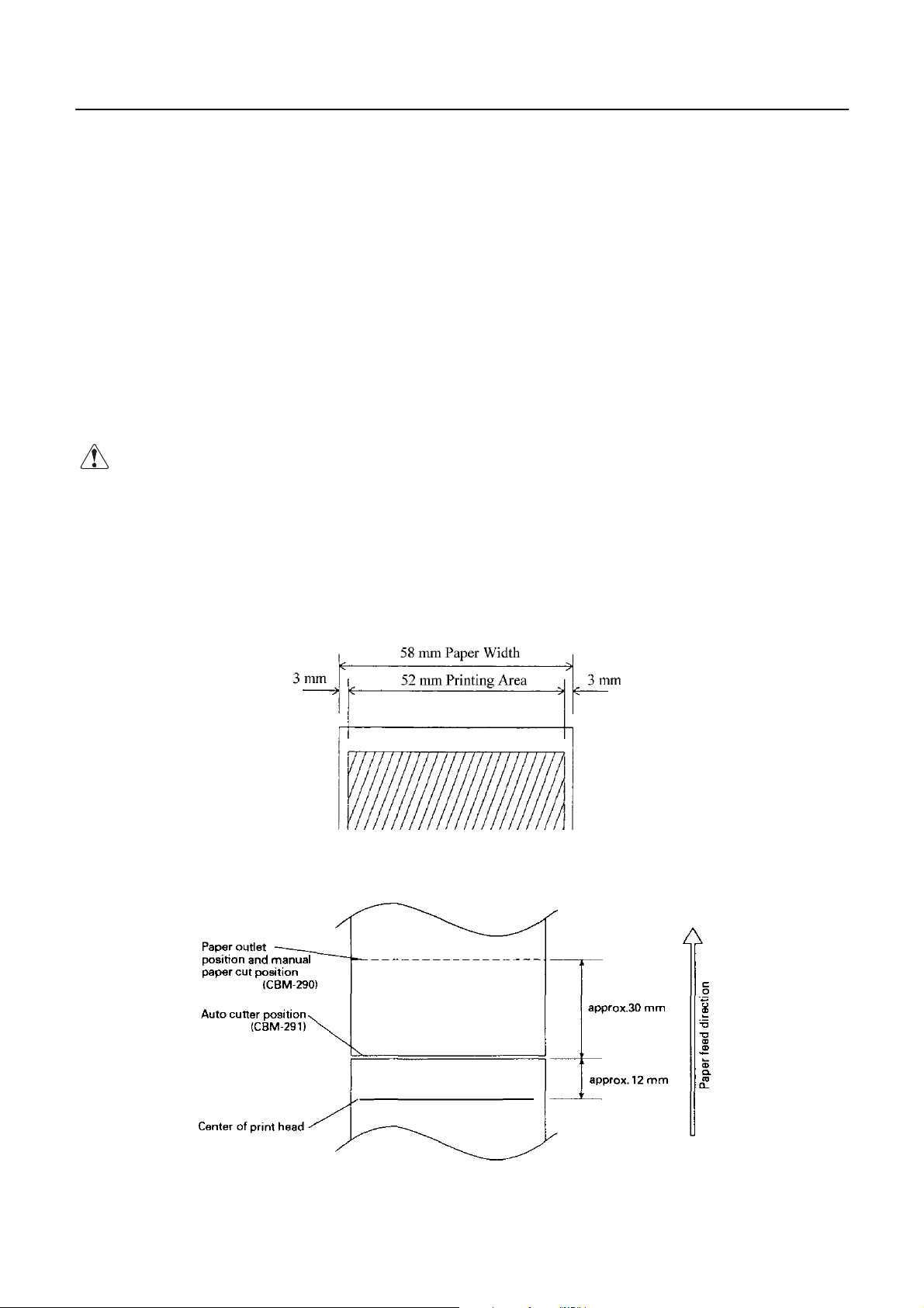
2.3.2 Printing position
2.3.3 Position of printer head and auto cutter
4
CITIZEN

2.4Specified Power Supply
The following specifications is required for Power supply.
VCC : DC 5V ± 5% 0.2 - 0.5 A
VP : DC24V±5% 2 - 3 A (6A or more at peak)
Avoid using power supply which its power capacity of power current is extremely high.
2.5Outer appearances and parts name
2.5.1 Outer appearances and parts name
CBM-290/291 User’s Manual
5
CITIZEN

CBM-290/291 User’s Manual
2.5.2 Explanation of each parts
• Front cover
Open/close this cover in case of paper change or paper jam.
• Paper lamp
Lights up when paper runs out.
• Feed switch
Press this switch to feed the paper. Pressing this switch keeps paper feeding continuously.
• Mechanism lock lever
This lock lever is used to pull down the printer mechanism to lift up the print head and to remove the paper
manually. Or move the cutter blade in case the cutter blade is locked due to paper jam.
• Head - up lever
This is the lever to lift up print head.
• Cutter blade(For CBM-290)
Used to cut the paper manually.
• Mounting bracket
Used to mount this equipment on the rack etc.
• Interface connector
Connect a cable for power supply and interface to this connector.
• DIP switch
Used to set the initial setting such as the type of interface (serial/parallel) or print density etc.
• FG terminal
Used to earth the frame of main body. Connect it properly.
• Auto paper cutter (CBM-291 only)
Paper is cut automatically by command. Complete full cut or partial cut (one tear point remains) can be
specified.
6
CITIZEN
CBM-290/291 User’s Manual
3. Operation
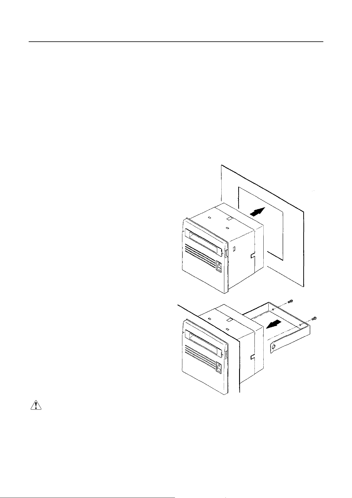
3.1 Rack mounting
(1) Put the main body into the rack as shown in the following drawing.
(2) Hold the main body from rear side with mounting bracket, fasten the screws to fix the main body.
(3) After mounting, make sure that front cover opens/closes properly.
(4) In fasten screws, do not fasten the screws until the main body is deformed.
This may be abnormal force onto the main body as well as be a cause of breakage.
(5) Thickness of rack panel to fix the main body is to be approx. 1 - 3 mm.
Precautions for Installation
• This printer does not support natural falling of
paper with full cut by auto cutter.
• Obstruction such as door, etc. shall not be located
in front of the front cover. Otherwise, paper
ejection is obstructed resulting in paper jam or the
like.
Cautions :
For mounting bracket, length of the screws must be 15 mm or less.
7
CITIZEN

CBM-290/291 User’s Manual
3.2 Connecting a cable for p ower supply and interface
(1) Make sure that main power supply is turned OFF before connecting this cable.
(2) Prepare power supply which satisfies the power voltage and current capacity specified in this manual.
(3) Firmly connect, in appropriate direction, the power supply and the main body using this cable.
As shown in the drawing, this connector locates on the rear side of main body.
This cable integrates the cable for power supply and the cable for interface.
(4) Connect this cable to external power supply.
Pay attention not to connect power supply cable in reverse polar.
(5) Earth the frame of main body.
Earthing this is recommended to avoid noise and electronic statistic problem. For connecting,
fix it with FG terminal on rear side properly.
8
CITIZEN

CBM-290/291 User’s Manual
3.3 Opening/closing front cover
(1) Applying your finger on the projection on the left side of the front panel, pull it forward when the lock is
released. It opens by about 180 ° centering around the fixed axis.
(2) For closing, pressing the front panel, tightly close it until click sound is heard. Also, confirm, on closing,
that paper is free of slack.
9
CITIZEN

CBM-290/291 User’s Manual
3.4 Paper feeding
With the LF switch pressed once, paper is fed by one line. Paper is fed while it is continuously pressed.
Do not pull paper forcibly to feed paper. Use the LF switch. While the front cover is open or printer mechanism
is pulled down, paper can be fed. But, do not do this often. This may cause a paper jam, etc.
3.5 Auto paper loading function
This printer equips a function to feed the paper automatically when a new paper for replacement is inserted into
paper inlet of printer mechanism.
This printer feeds paper automatically when the printer detects the paper in paper inlet.
3.6 Setting roll paper
1. Open the front cover.
2. Cut the edge of paper at a right or bent angle as the following drawing.
Insert the edge of paper into the paper inlet of the printer mechanism.
When paper is inserted into paper inlet in printer mechanism, paper is loaded automatically.
3. Make sure paper winding direction.
4. After setting paper, set roll paper inside of main unit.
5. Eliminating slack on the printing paper and close the front panel.
6. Feed paper by pressing Feed switch, if necessary.
∗ Factory setting is Head up position.
Make sure to pull head up lever forward to pull down printer mechanism, Because auto paper feed can not
be carried out at had up condition.
∗ When any print data is remaining us print buffer, printer stars printing automatically after loading paper.
10
CITIZEN

CBM-290/291 User’s Manual
Make sure to pay attention to the followings.
1. In case that the paper is bent or the paper is not fed properly, set print head at head up condition and
remove the paper carefully by turning paper feed knob.
2. For replacing roll paper, set print head at head up condition, and remove the paper which remains in
printer unit carefully by turning paper feed knob.
11
CITIZEN

CBM-290/291 User’s Manual
3.7 Removing paper jam and canceling cutter lock
Remove paper jam or cancel cutter lock by following the procedure explained below.
(1) Open front cover
(2) Put mechanism lock lever inside of main body, pull down printer mechanism.
When paper remains inside of printer, remove this paper.
(3) Removing paper jam
Remove paper jam manually with care. To pull out the paper from printer mechanism,
pull it out carefully at head up condition.
(4) Canceling cutter lock
Remove paper inside of paper cutter and turn ON power. In case cutter blades to home position and
carries out initializing, cutter lock was cleared completely.
In case cutter does not return to home position or occurs some error again, turn OFF power,
turn the knob which locates on left bottom side of auto cutter to the front side as shown in the below,
then return cutter blade manually and remove the paper inside of auto cutter.
(5) After fixing the problem, pull down head up lever and return printer mechanism to its home position.
Cautions :
Since print head and motor are hot, do not carry out this action right after printing.
This may cause burning from this heat.
For removing the remaining paper, do not touch the surface of print head and motor.
12
CITIZEN

CBM-290/291 User’s Manual
3.8Self print function
By supplying power as pushing FEED switch or send RESET signal to this printer,
type of characters which is used, ROM version and DIP switch setting etc are automatically printed.
For CBM-291, paper is automatically cut off after this self printing.
3.9PE and Mechanical alarm
3.9.1 Paper end (PE)
This sensor detects the existence of paper. Printer stops printing when roll paper runs out, outputs BUSY and
PE signal and lights up PAPER lamp. When new roll paper is set, this signal is canceled and PAPER lamp
lights off. And then, printer starts printing and becomes data waiting status. When any print data is remaining
in print buffer, make sure that printer starts printing the data after new roll paper is set.
3.9.2 Mechanical alarm
This printer stops printing, stops supplying motor and print head with power and outputs BUSY signal and
FAULT (in Parallel interface) signal to host computer, when the motor of printer mechanism is locked, auto
paper cutter is locked, or temperature of print head is getting high. In this case, turn OFF power supply and
clear the problem. To make printer stand-by mode, turn ON power supply after clearing the problem.
Make sure that the data which is stored in the buffer is to be cleared due to power supply is turned OFF.
Absolutely, do not carry out clearing the problem during power is ON.
• Auto paper cutter lock, paper jam.
Turn OFF power supply and clear the problem. To make printer ready for print, turn ON power again after
clearing the problem. In this case, the print data which is remaining inside of print buffer is cleared due to
power supply is turned OFF. Absolutely, do not carry out clearing problem supplying power.
• Head-up condition
Pull down had up lever forward. Print head is pulled down and error signal is cleared, then printer
becomes ready for print.
• Heating up of print head temperature
When temperature of print head is getting high due to continuous printing etc., printer stops printing.
During temperature of print head is high, any operation is not available, keep printer without printing.
As soon as temperature of print head goes low, error signal is canceled automatically and printer
becomesready for print.
13
CITIZEN

CBM-290/291 User’s Manual
4. Dip switch setting
Dip switch locates on the rear side of main body. Make sure that power is turned OFF before changing Dip
switch settings. Change during power is ON can not be effective.
DIP SWITCH
ON OFF FACTORY SETTING
DS1-1 AUTO CUTTER EQUIPPED NONE OFF = CBM-290
ON = CBM-291
2 CR SELECTION LF ENABLE LF DISABLE OFF
3 PRINT DENSITY STANDARD DARKER OFF
4 DTR-DSR/XON-XOFF XON-XOFF DTR/DSR OFF
5 INTERFACE OFF
6 " SEE BELOW OFF
7" OFF
8
DS1-
8 7 6 5 INPUT METHOD PARITY BAUD RATE
OFF OFF OFF OFF PARALLEL INPUT -- -OFF OFF OFF ON SERIAL INPUT NONE 1200 bps
OFF OFF ON OFF " " 2400 bps
OFF OFF ON ON " " 4800 bps
OFF ON OFF OFF " " 9600 bps
OFF ON OFF ON " " 19200 bps
OFF ON ON OFF " ODD 1200 bps
OFF ON ON ON " " 2400 bps
ON OFF OFF OFF " " 4800 bps
ON OFF OFF ON " " 9600 bps
ON OFF ON OFF " " 19200 bps
ON OFF ON ON " EVEN 1200 bps
ON ON OFF OFF " " 2400 bps
ON ON OFF ON " " 4800 bps
ON ON ON OFF " " 9600 bps
ON ON ON ON " " 19200 bps
Remarks : For CBM-290, It make Error when ON is selected for DS1-1.
DS1-4 is ignored when parallel input is specified.
Some specifications has been selected in factory setting by jumper as follows.
"OFF
Jumper International model
J1 Short
J2 Short
J3 Short
J4 Short
J5 Short
J6 Short
J7 Short
J8 Open
International model
International character : U.S.A.
Auto-loading : Enabled
Input Buffer : 4 K bytes
Serial communication bit length : 8 bit
14
CITIZEN

CBM-290/291 User’s Manual
5. Connecting connector
Configuration of the connector for power and interface which is packed in this box is as follows.
Make sure to confirm the following configuration before connecting the connector.
5.1 Function of each connector pins
PIN NO. SIGNAL NAME I/O FUNCTION
1 – 3 VCC OUTPUT POWER SUPPLY FOR CIRCUIT (+5V)
4 – 6 GND GND
7 – 12 VP INPUT POWER SUPPLY FOR OPERATION(+24V)
13 – 18 P-GND GND FOR OPERATION
19
20 ERROR OUTPUT ERROR LED OUTPUT (Can be connected directly.)
21 Not available
22 DTR OUTPUT SERIAL INTERFACE DTR
23 TXD OUTPUT SERIAL INTERFACE TXD
24 RXD INPUT SERIAL INTERFACE RXD
25 DSR INPUT SERIAL INTERFACE DSR
−
Not available
26 STB INPUT PARALLEL INTERFACE STROBE
27 BUSY OUTPUT PARALLEL INTERFACE BUSY
28 ACK OUTPUT PARALLELINTERFACE ACK
29 DATA 0 INPUT PARALLEL INTERFACE DATA 0
30 DATA 1 INPUT PARALLEL INTERFACE DATA 1
31 DATA 2 INPUT PARALLEL INTERFACE DATA 2
32 DATA 3 INPUT PARALLEL INTERFACE DATA 3
33 DATA 4 INPUT PARALLEL INTERFACE DATA 4
34 DATA 5 INPUT PARALLEL INTERFACE DATA 5
35 DATA 6 INPUT PARALLEL INTERFACE DATA 6
36 DATA 7 INPUT PARALLEL INTERFACE DATA 7
37 PE OUTPUT PARALLEL INTERFACE PE
38 FAULT OUTPUT PARALLEL INTERFACE FAULT
39 RESET INPUT PARALLEL INTERFACE RESET
40
Using connector : LY20-40P-DT1-P5 (JAE) or equivalent
Applicable connector : LY10-DC40 (JAE) or equivalent
−−
Not available
15
CITIZEN

CBM-290/291 User’s Manual
5.2Precautions
1. For LED ERROR , there is a resister of 330 Ohm on the circuit side to make current value 10 mA.
Please use LED which its voltage is approx. 2V. LED over 10 mA may break a control board.
2. Make sure to supply power to all pins of power supply for circuit and power supply for operation to keep
required current capacity.
3. Serial interface equips a driver and receiver of RS-232C, make sure to use it at RS-232C level.
4. RESET terminal is pulled up by 3.3K Ohm. Make sue to make this terminal NC, when this terminal is not
used.
5. Absolutely, do not carry use No.19, No.21 and No.40 pins. Since they are used for printer main unit.
In case they are used, they may cause abnormality or break control board.
6. Parallel Interface
6.1Specifications
Data input method : 8 bit parallel signal (DATA0 ∼ 7)
Control signals : ACK, BUSY, STB, FAULT, PE, RESET
6.2Explanation of input / output signals
DATA0 ∼ 7 : 8 bit parallel signal (Positive logic)
STB : Strobe signal to read 8 bit data (Positive signal)
RESET : Signal to reset control board
ACK : 8 bit data request signal. Pulse signal output at the end of the BUSY signal (Negative logic)
BUSY : Signal to indicate BUSY state of the printer.Input new data for "LOW" (Positive logic)
FAULT : Signal which is made "LOW" when printer is in alarm state.(Negative logic)
PE : Signal which is output when paper runs out.(Positive logic)
16
CITIZEN

6.3 Electrical characteristics
(1) Input Signal Level
All the input signals are at TTL level.
"HIGH" level :0.7Vcc MIN
"LOW" level : 0.3Vcc MAX
(2) Output Signal Level
All the input signals are at TTL level.
"HIGH" level :Vcc – 0.1V MIN
"LOW" level : 0.1V MAX
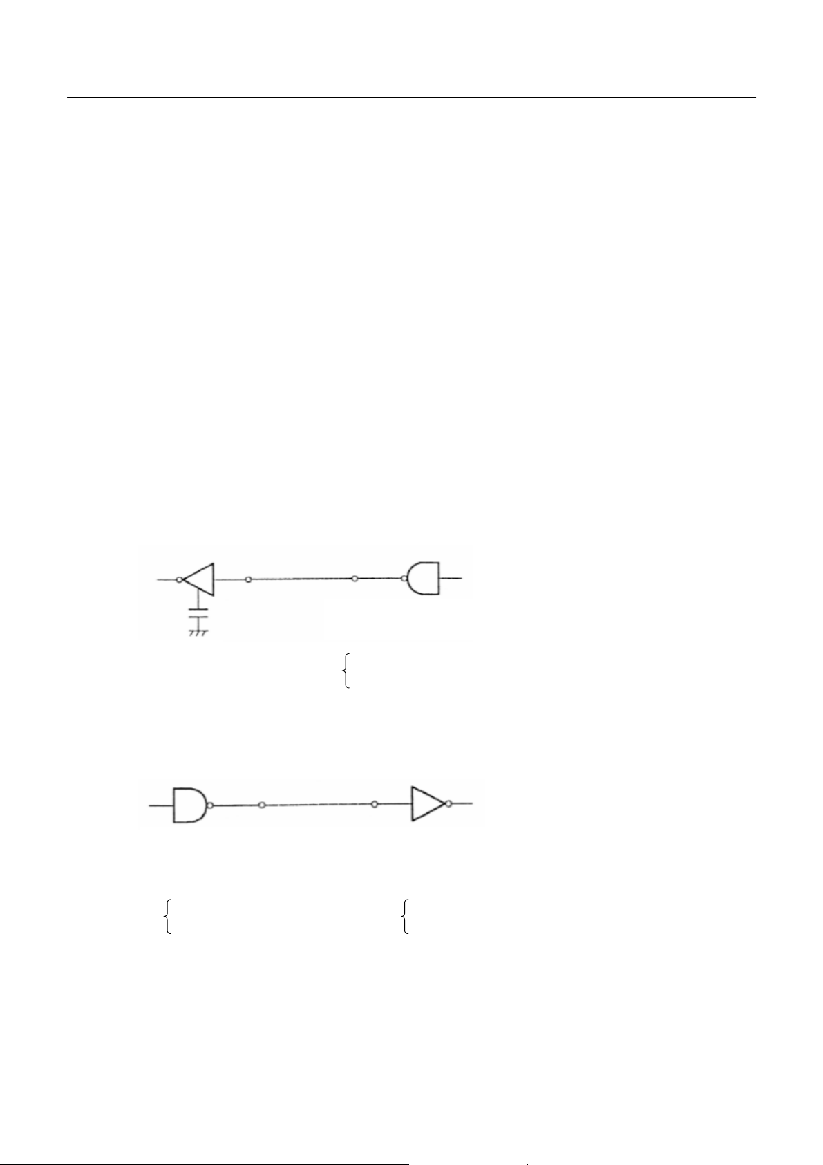
(3) I/O Conditions
Input signal of STB and RESET are pulled up by 3.3K Ohm. Others are pulled up by 50K Ohm.
[Printer side] [Host side]
CBM-290/291 User’s Manual
All the output signals are pulled up by 50K Ohm.
17
CITIZEN
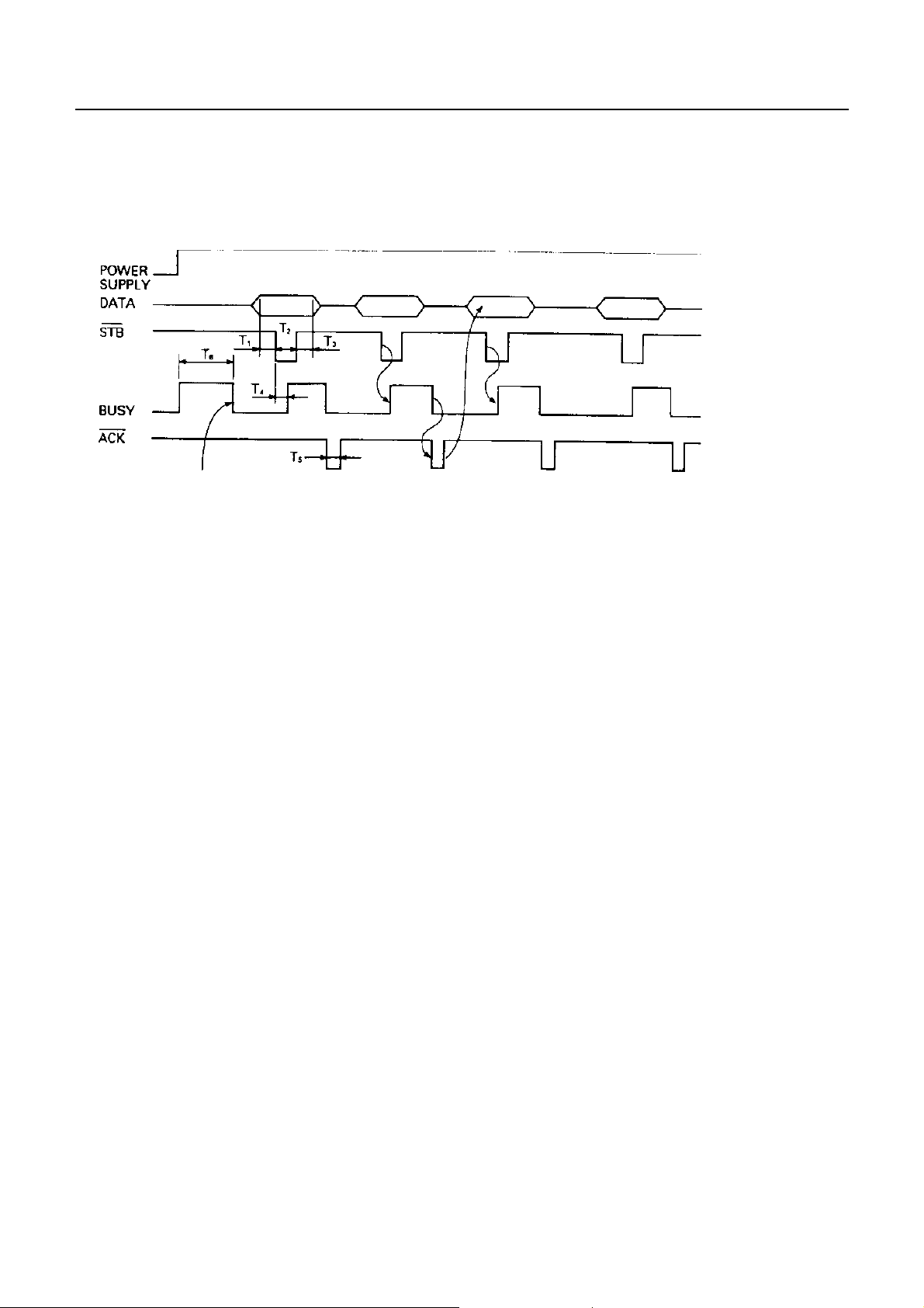
6.4 Timing chart
(1) Data Input and Printing Timing
ACK is not outputted.
T1, T2, T3 : 0.5 micro sec. MIN
CBM-290/291 User’s Manual
T4 : 270 ns MA X
T5 : 2.3 micro sec. TYP
T6 : 500 ms MIN (On supplying power)
6.5Data receiving control
When BUSY signal is "LOW", data from the host can be received. When it being "HIGH", data can not be
received.
6.6Buffering
4 K bytes input buffer is incorporated. Due to this large buffer, host side is released immediately.
18
CITIZEN

7. Serial Interface
7.1Specifications
(1) Data transfer system: Asynchronous
(2) Baud rates
1200, 2400, 4800, 9600, 19200 bps (Selectable by user)
(3) Configuration of one word
Start bit : 1 bit
Data bit : 8 bits
Parity bit : Add/even or no parity (Selectable by user)
Stop bit : 1 bit or more
(4) Signal polarity
RS-232C
• Mark = logic " 1" (–3V ∼ –12V)
• Space = logic " 0" (+3V ∼ +12V)
CBM-290/291 User’s Manual
(5) Receiving data (RD signal)
RS-232C
• Mark = 1
• Space = 0
(7) Receiving control (DTR signal)
RS-232C
• Mark : Data transfer not available
• Space : Data transfer available
(8) Transmission control (TD signal)
DC1 code (11H) X-ON : Data reception available
DC3 code (13H) X-OFF : Data reception not available
19
CITIZEN

7.2 Explanation of Input / Output signals
7.2.1 Input / Output signals
(1) RD
Serial receiving data signal. On occurrence of framing error, overrun error, or parity error,
the data is printed as "?".
(2) DTR
When this signal is READY, write data or a command. When they are written in BUSY,
overrun error is occurred and data is ignored. Even during printing, data can be loaded in
the input buffer. Further, BUSY can take place on supply of power, during test printing,
during on-line, or on resetting.
(3) TD
When, while in data reception, the rest of input buffer on the printer side goes less than
128 bytes , DC3 (13H) data reception impossible signals are output.
When the rest of input buffer goes more than 256 bytes, DC1 (11H) data reception possible signals
CBM-290/291 User’s Manual
are output to the host. When DTR/DSR control having been selected in status
information transmission, it is first confirmed that DSR is "space" and data is sent.
When DTR/DSR control has not been selected, DSR is ignored and data is transmitted.
(4) FG
Case GND
(5) GND
Common GND on the circuit.
20
CITIZEN

7.3Date configuration
1 Start bit
2 Data bit (+ parity bit)
3Stopbit(1ormore)
(1) Start Bit
CBM-290/291 User’s Manual
In 1/2 bit from the mark-to-space starting edge, state is read once again. When "space" state is confirmed,
it is recognized as the start bit. If it is "mark" state, it is not taken as the start bit. Without taking it as an
error, detection of a start bit is carried out once again.
(2) Data Bit + Parity Bit
Data bit and parity bit are sampled at 1/2 start bit for time length equal to 1 bit. The state thus sampled is
taken as the data for the bit concerned. Bits are named as Bit 0, Bit 1, ..... parity bit counted from the one
close to the start bit.
(3) Stop Bit
The stop bit is a mark level of 1 bit or more. With "space" having been detected on detection of a stop bit,
framing error takes place.
7.4Error detection
Parity, framing, and overrun are detected. On detection of any error, the data are stored in the buffer as "?".
(1) Framing Error
With "space" state having been detected on detection of a stop bit, error takes place. The data are stored in
the buffer as "?".
(2) Parity Error
With an error having been detected under specifying parity check, the data is stored in the buffer as "?".
(3) Overrun Error
On detection of an overrun error, the data are stored in the buffer as "?".
21
CITIZEN
CBM-290/291 User’s Manual
7.5Data receiving control
When DTR/DSR control having been selected, with BUSY signal at "LOW" , data from the host side are
received. With the signal at "HIGH", they can not be received.
When DTR/DSR control not having been selected, after X-ON transmission, data is received from the host side.
No transmission of data can take place after X-OFF is transmitted.
7.6Buffering
Data transfer to the input buffer include DTR signals and TD signals as the control signals concerned.
(1) DTR signals (See 7.2. (2).)
(2) TXD signals (See 7.2. (3).)
7.7 Electrical characteristics
(1) RS-232C Circuit
Input (RXD, DSR)
[Printer side] [Host side]
MAX 232 equivalent
Output (DTR, TXD)
MAX 232 equivalent
(−8V) : When busy Space
DTR
(+8V) : When ready
RXD
Mark = (−8V) : Stop bit
Space = (+8V) : Start bit
Mark = (−8V) : 1
TXD
Space =(+8V) : 0
22
CITIZEN

8. MAINTENANCE AND SERVICE
For the information on maintenance and service, please contact our dealer.
CBM-290/291 User’s Manual
23
CITIZEN

9. Print Control Function
g
g
p
p
p
)
{
)
)
9.1 Command Lit
CONTROL CODE
1HT
2CR
3LF
4 ESC SP
5!
6%
7&
8*
9
10 2
11 3
12 @
13 D
14 E
15 G
16 J
17 R
18 c3
19 c4
20 c5
21 d
22
23 t
24 v
25 u
26
27 V
28 $
29 ¥
30 GS k
31 w
32 h
33 H
34 f
35 *
36 /
37 :
38 ^
39 ESC =
40 a
41 i
42 m
–
CBM-290/291 User’s Manual
FUNCTION
Horizontal tab command
Print command
Printingandpaper feed
Settingthe right space amount of the character
Collective specifyingprintingmode
Specifying/cancelingdownload character set
Definingdownload characters
Specifyingthe bit image mode
Specifying/cancelingunderline
Specifying1/6-inch line feed rate
Settingline feed rate of minimumpitch
Initializingthe Printer
Settinghorizontal tabposition
Specifying/cancelinghighlightin
Specifying/cancelingdoubleprintin
Printingand feedingpaper n/203 inch
Selectingthe international characters
No
No
Enabling/disablingthepanel switches
Printingand feedingthepaper byn lines
NOP
Selectingthe character code table
Transmittingtheprinter status(Serial type
NOP
Specifying/cancelingthe inverted characters
Specifying/cancelingthe 90° - right-turned characters
Specifyingthe absolutepositions
Specifyingthe relativepositions
Printingthe bar code
Selectingthe horizontal size(scale factor)of bar code
Selectingthe height of the bar code
Selectingofprintposition of HRI code
Selectingthe font of HRI code
Definingthe download bit image
Printingthe download bit image
Starting/endingmacro definition
Executingthe macro
Data input control
Aligningthe characters
Activatingauto cutter(Full cut
Activatingauto cutter(Partial cut
24
CITIZEN

9.2 Command Details
(1) Horizontal Tab Command (HT)
Code : (09)h
Shifts the printing position to the next horizontal tab position. The horizontal tab position is set by ESC D.
Initial setting of the horizontal tab position is each 8 characters in 9th, 17th, 25th, 33rd
(2) Print Command (CR)
Code : (0D)h
1) When DS 1 -2 is OFF:
This command is ignored.
2) When DS 1- 2 is ON:
With data held inside the internal print buffer, printing and line feed are performed.
Without data inside the internal print buffer, however, no printing is performed.
(3) Printing and Paper Feed Command (LF)
CBM-290/291 User’s Manual
,
columns.
Code : (0A)h
Prints data inside the input buffer and feeds lines based on the line feed amount having been set.
(4) Setting the right space amount of the characters (ESC SP n)
Code : (1B)h + (20)h + n
*{0≤ n ≤ 20} Data is described in Hex code.
The rightward space amount is set in dot unit (1/203 inch unit). In the initial value, it is n=0.
The rightward space amount in double wide mode is made double of the set volume.
(5) Collective Specifying Printing Mode (ESC ! n)
Code: (1B)h + (21)h + n
*{0≤ n ≤ FF} Data is described in Hex code.
Printing mode is assigned. Each n bit indicates the following:
VALUE
BIT FUNCTION 0 1
0 Character Font Font A Font B
1 Undefined
2 Undefined
3 High-lighting Canceled Specified
4 Double height Canceled Specified
5 Double width Canceled Specified
6 Undefined
7 Underline Canceled Specified
25
CITIZEN

CBM-290/291 User’s Manual
• With double height and double width being specified simultaneously, double wide and double high
characters are consisted.
• An underline is attached to the full character width, which, however, is not attached to the part having
been skipped by the horizontal tab. Neither is it attached to 90°-right-turned characters.
• The underline width is as having been specified by <ESC - >.
(The default setting is 1 dot width. )
In case that double wide character and normal character exist in same one line, the layout of underline
is consistent one.
(6) Specifying/Canceling Download Character Set (ESC % n)
Code: [1B]h + [25]h + [n]
*{0≤ n ≤ FF} data is described in Hex code.
Specifying/canceling download characters. Download characters and download bit images cannot be
defined simultaneously. Further, only the lowest bit (n0) is valid for n.
The lowest bit (n0) indicates the following.
n0 Function
0 Canceling download character
1 Specifying download character
(7) Defining Download Character (ESC & s n m a (D1D2 - Dn))
Code: [1B]h + [26]h + s +n +m +a +Dn
* {s = 03}
{20 (Hex) ≤ n ≤ 7E (Hex)}
{20 (Hex) ≤ m ≤ 7E (Hex)}
{0 ≤ a ≤ 0A (Hex)}
Defines the font of download characters of alphanumeric characters.
• "s" indicates the number of bytes in vertical direction.
• "n" indicates the start character code and m the end character code. To define only one character,
• set n=m.
• Character codes definable includes 95 ASCII codes in total between <20>H - <7E>H.
• "a" indicates the number of dots in horizontal direction for definition.
• Dn is the data to be defined, which indicate a pattern equal to "a" dot in horizontal
• direction from the left end. The rest of the pattern on the right side is filled with space.
• The rest of data to be defined is s x a.
• Download characters thus defined remain valid until redefinition, ESC @ execution,
• GS * execution, or power OFF is practiced.
26
CITIZEN
[EXAMPLE]
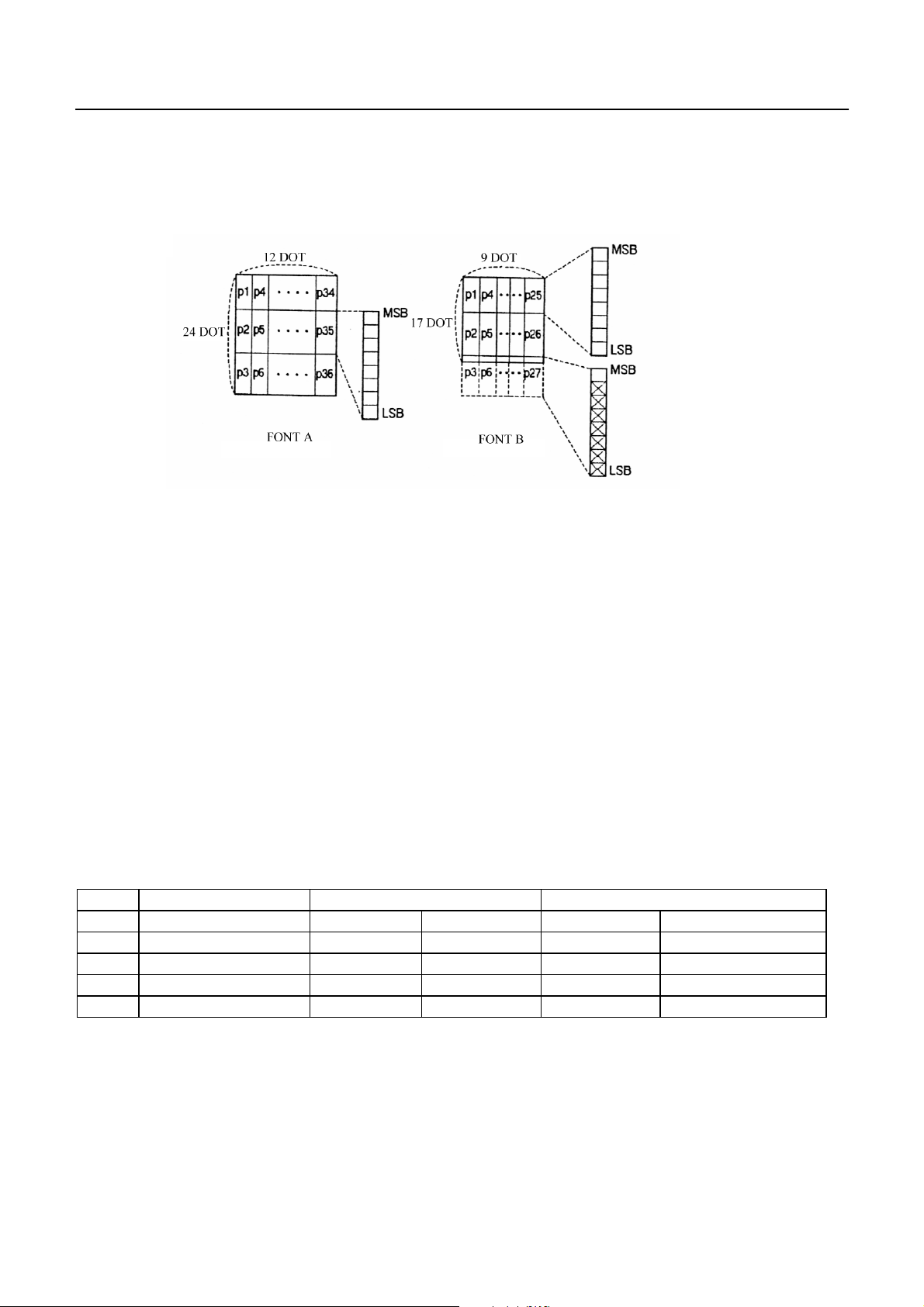
(8) Specifying the Bit Image Mode (ESC * m n1 n2 D1- Dn)
CBM-290/291 User’s Manual
Code : [1B]h + [2A]h + m + n1 + n2 + Dn
* {m= bit image mode (See the table below.)}
{0 ≤ n1 ≤ FF}
{0 ≤ n2 ≤ 02} Data is described in Hex code.
According to the number of dots specified in n1, n2, specify the bit image of mode n.
• The no. of dots printed is divided by 256, whose quotient is taken as n2 and residualas n1.
• The total no. of dots printed in the bit image is equal to n1 + (256 x n2).
• When bit image data have been input in excess of dot position of one line (448 dots) , the excess
• data are discarded.
• d is bit image data, the bits subject to printing are taken as "1" and those not as "0".
• The bit image modes specified by m are shown as follows:
VERTICAL DIRECTION HORIZONTAL DIRECTION
m(Hex) MODE NO. OF DOTS DOT DENSITY DOT DENSITY MAX. NO OF DOTS
0 8-dot signle density 8 67 DPI 101 DPI 224 (208)
1 8-dot double density 8 67 DPI 203 DPI 448 (416)
32 24-dot single density 24 203 DPI 101 DPI 224 (208)
33 24-dot double density 24 203 DPI 203 DPI 448 (416)
27
CITIZEN

CBM-290/291 User’s Manual
• When the values set in m (bit image mode) are out of the above range, the data following after n1 is
processed as normal printing data.
• After completion of bit image printing, printer returns to normal data processing mode.
(9) Specifying/ Canceling Underline (ESC - n)
Code: [1B]h + [2D]h + n
*{0≤ n ≤ 02} data is described in Hex code.
Specifying/canceling an underline.
• An underline is attached to the full character width. It is, however,not attached to the part
• having been skipped by horizontal tab command.
• An underline is not attached to a 90 ° - right-turned characters.
• Types of underlines by n value are shown below:
n (Hex) Type
0 Canceling an underline.
1 Specifying an underline for 1-dot width.
2 Specifying an underline for 2-dot width.
(10) Specifying 1/6 inch line feed rate (ESC 2)
Code : [1B]h + [32]h
The line feed rate per line is specified by 1/6 inch.
(11) Setting line feed rate of minimum pitch (ESC 3 n)
Code : [1B]h + [33]h + n
*{0≤ n ≤ FF} data is described in Hex code.
The line feed rate per line is specified by n/360 inch.
• The initial value is n = 60(1/6 inch)(18H), being 4.23 mm line feed rate.
28
CITIZEN

CBM-290/291 User’s Manual
(12) Initializing Printer (ESC @)
Code : [1B]h + [40]h
Clears data stored in the print buffer and brings various settings to the initial state (Default state).
• Data inside the internal input buffer are not cleared.
• Dip switches setting are read once again.
(13) Setting Horizontal Tab Position (ESC D n NUL)
Code : [1B]h + [44]h + n [00]h
*{0≤ n ≤ FF} Data is described in Hex code
Specifying a horizontal tab position.
• "n" indicates the no. of columns from the beginning to the horizontal tab position. At this time, n= set
position - 1 is to be specified. For example, to set the position at 9th column, n=8 is to be specified.
• The tab position is set at position where it is "character width x n" from the line beginning. The
character width, at this time, includes the rightward space amount. In double wide characters, it is
made double of the ordinary case.
• T ab positions can be specified are maximum 32. Specifying exceeding this is ignored.
• ESC D NUL clears all the set tab positions. Following clearing, horizontal tab command is ignored.
• Initial value is specified for each eight characters(9.17.25.33.) of ANK characters.
(14) Specifying/canceling highlighting (ESC E n)
Code : [1B]h + [45]h + n
*{0≤ n ≤ FF} Data is described in Hex code.
Specifying/canceling the highlighting characters.
• "n" is valid only for the lowest bit (n0).
• Control by the lowest bit (n0) is shown as follows:
n0 Type
0 Canceling highlighting.
1 Specifying highlighting.
• This is effective to all characters.
• Dot configuration of a highlighted character includes one extra dot added at its side.
• The print result of Double printing and highlight character printing is completely same.
29
CITIZEN
(15) Specifying/canceli ng Double Printing (ESC G n)
Code : [1B]h + [47]h + n
*{0≤ n ≤ FF} Data is described in Hex code.
Specifying/canceling the double printing.
• "n" is valid only for the lowest bit (n0).
• Control by n is shown as follows.
n0 Type
0 Canceling double printing.
1 Specifying double printing.
• The print result of Double printing and highlight character printing is completely same.
(16) Printing and feeding paper at minimum pitch (ESC J n)
Code : [1B]h + [4A]h + n
*{0≤ n ≤ FF} Data is described in Hex code.
CBM-290/291 User’s Manual
Prints data inside the print buffer and feeds paper by n/360 inch.
• Specified volume does not remain.
• The beginning of the line is to be considered as the next printing start position.
• Initial value is not defined.
(17) Selecting International Characters (ESC R n)
Code : [1B]h + [52]h + n
*{0≤ n ≤ 0A) Data is described in Hex code.
Selecting international characters.
• Depending on the value of n, following character sets are specified.
n(Hex) CHARACTER SET
0 U.S.A.
1 France
2Germany
3 U.K.
4Denmark1
5 Sweden
6 Italy
7Spain
8 Japan
9 Norway
10 Denmark 2
• The initial value of n indicates the character set specified by Jumper setting (J1 - J3).
30
CITIZEN

(18) NOP (ESC c3)
(19) NOP (ESC c5)
(20) Enabling/Disabling Panel Switch (ESC c 5 n)
Code : [1B]h + [63]h + [35]h + n
*{0≤ n ≤ FF} Data is described in Hex code.
Selecting the LF switch valid/invalid.
• "n" is valid only in the lowest bit (n0).
• "n" bit means the followings.
N0 Condition
0 LF SW valid.
1 LF SW invalid.
• The initial value of n is "0".
CBM-290/291 User’s Manual
(21) Printing and Feeding the paper by n lines (ESC d n)
Code : [1B]h + [64]h + n
*{0≤ n ≤ FF} Data is described in Hex code.
Prints data inside the buffer and feeds paper by n lines.
• Specified line does not remain.
• The beginning of the line is to be considered as the next printing start position.
• The initial value is not defined.
31
CITIZEN

(22) Generating specified Pulse (ESC p m n1 n2)
Code : [1B]h + [70]h + m + n + n2
* {m = connector pin No. (See table below.)}
{0 ≤ n1 ≤ FF}
{0 ≤ n2 ≤ FF} Data is described in Hex code.
Signals specified by n1, n2 are output to Connector Pin m.
• Bit m (m0) means the followings.
m0 Condition
0 DrawerkickNo.2pin
1 DrawerkickNo.5pin
• ON time is considered as n1 x 2ms and OFF time as n2 x 2ms.
• When m is out of the defined range, n1, n2 are discarded, where no signals are output.
• Drive duty of Drawer is shown below:
CBM-290/291 User’s Manual
ON time
ON time + OFF time
≤ 0.2
(Take OFF time as being 4 times or more longer than ON time.)
(23) Selecting Character Code Table (ESC t n)
Code : [1B]h + [74]h + n
*{0≤ n ≤ 1} Data is described in Hex code.
Selecting Page n on the character code table:
• "n" means the followings.
n (Hex) Condition
0 IBM Character #2
1 Japanese Character
• The initial value of n is specified by Jumper setting (J1 - J3).
32
CITIZEN

CBM-290/291 User’s Manual
(24) Transmitting the printer status (ESC v)
Code : [1B]h + [76]
Current printer status is transmitted..
• Status sent out consists of 1 byte whose content is as in the table below.
• In DTR/DSR control, after receptible state of the host (DSR signal being in SPACE state) is confirmed,
only 1 byte is transmitted. In XON/XOFF control, DSR signal state not being confirmed, only 1 byte is
transmitted.
• In DTR/DSR control, when the host is in unreceptible state(DSR signal being in
• MARK state), it waits until receptible state is created.
• In paper end (paper near end) status, this command may be unreceptible state due to BUSY state.
• Remarks. This command is valid only for serial interface model.
VALUE
BIT FUNCTION 0 1
0 Not defined
1 Not defined
2 Paper end With paper Without paper
3 Not defined
4 Not used Fixed to 0 –
5 Not defined
6 Not defined
7 Not defined
(25) Transmitting the status of Peripheral Equipment (ESC u n)
Code : [1B]h + [75]h + n
*{n=0}
Current status of connector pin No.3 is transmitted.
• "n" means the followings.
n (Hex) Condition
0 Drawer Kick Connector No. 3
• Status transmitted consists of 1 byte whose content is as in the table below.
• Any equipment has not been connected to this connector, Bit 0 of n is always "1".
• In DTR/DSR control, after receptible state of the host (DSR signal being in SPACE state) is
• confirmed, only 1 byte is transmitted. Further, in XON/ XOFF control, DSR signal state
• not being confirmed, only 1 byte is transmitted.
• In DTR/DSR control, when the host is unreceptible state (DSR signal being in MARK state),
• it keeps waiting until receptible state is created.
33
CITIZEN
BIT FUNCTION 0 1
0 Not defined
1 Not defined
2 Paper end Paper remains Paper out
3 Not defined
4 Not used Fixed to 0 –
5 Not defined
6 Not defined
7 Not defined
(Remarks) This command is valid only for serial interface mode.
(26) Specifying/Canceling Inverted Characters (ESC { )
Code : [1B]h + [7B]h + n
*{0≤ n ≤ FF} Data is described in Hex code.
CBM-290/291 User’s Manual
VALUE
Specifying/canceling inverted characters.
• "n" is valid only for the lowest bit (n0).
• Bit n (n0) means the followings.
n0 Condition
0 Canceling inverted characters.
1 Specifying inverted characters.
• Inverted printing means printing the line at 180° turned.
• This is valid only when this is specified at the beginning of a line.
• The initial value of n is "0".
(27) Specifying/Canceli ng 90° -right- turned Characters (ESC V n)
Code : [1B]h + [56]h + n
*{0 ≤ n ≤ 1} Data is described in Hex code.
Specifying/canceling characters 90°-right- turned character.
• No underlines are attached to 90°-right- turned characters .
• "n" means the followings.
n (Hex) Condition
0
1
Canceling
Specifying
90° -right- turned Characters
90° -right- turned Characters
• The initial value of n is "0".
34
CITIZEN

CBM-290/291 User’s Manual
(28) Specifying Absolute Positions (ESC $ n1 n2)
Code : [1B]h + [24]h + n1 + n2
*{0≤ n1 ≤ FF}
{0 ≤ n2 ≤ 1} Data is described in Hex code.
The printing start position is specified in the number of dots from the beginning of line. (1/20 inch unit)
• The number of dots is divided by 256, whose quotient is taken as n2 and the residual as n1.
Therefore, the printing start position is equal to n1 + n2 x 256 from the beginning of line..
• Specifying beyond the line end is ignored.
• In case underline is specified, no underline is provided to the skipped portion.
(29) Specifying Relative Positions (ESC ¥ n1 n2)
Code : [1B]h + [5C]h + n1 + n2
*{0≤ n1 ≤ FF}
{0 ≤ n2 ≤ FF} Data is described in Hex code.
The printing start position is specified in the number of dots from the current position.
• Rightward direction is taken as plus and leftward direction as minus.
• T o specify N dot in minus (left) direction, use a complement of N for assignment.
- N dots = 65536 - N
• The number of dots is divided by 256, whose quotient is taken as n2 and the residual as n1.
• Specifying exceeding the end of line is ignored.
• In case underline is specified, no underline is provided to the skipped portion.
(30) Bar Code Printing (GS k n Dn NUL)
Code : [1D]h + [6B]h + n + Dn + [00]h
*{0≤ n ≤ 7} Data are described in Hex code.
Specifying a type of bar code and printing bar codes.
• The beginning of line is considered as the next printing start position.
• Depending on the value of n, the following bar code can be selected.
• Dn indicates a character code to be printed.
n (Hex) Bar Code System Maximum Columns
0 UPC-A --1 UPC-E --2 JAN13 (EAN) --3 JAN 8 (EAN) --4 CODE 39 14
5ITF 24
6 CODABAR (NW-7) 18
7 CODE 128 15
35
CITIZEN

CBM-290/291 User’s Manual
• When data being held in the print buffer, this command is ignored.
• Regardless of the specified feed pitch, this command feeds the paper to be required to print a bar
code.
• When the character code Dn cannot be printed, the data following after this is printed as ordinary print
data.
• When a bar code whose number of characters to be printed is fixed has been selected,
• the number of characters have to be always made equal to the number of characters to be printed.
• When the horizontal direction exceeds one line length, the excess part is not printed.
(31) Selecting Bar Code width (GS w n)
Code : [1d]H + [77]H + N
*{2≤ n ≤ 4} Data is described in Hex code.
Selecting bar code width.
• The initial value of this width is "3".
(32) Selecting Bar Code Height (GS h n)
Code : [1d]H + [68]H + N
*{1≤ n ≤ FF} Data is described in Hex code.
Selecting bar code height.
• "n" indicates the number of dots in vertical direction.
• The initial value of n is "162".
(33) Selecting Printing Position of HRI Characters (GS H n)
Code : [1d]H + [48]H + N
*{0≤ n ≤ 3} Data is described in Hex code.
Selecting printing position of HRI characters in printing bar codes.
• "n" means the followings.
n (Hex) Printing Position
0 No printing
1 Above the bar code
2 Below the bar code
3 Both above and below the bar code
• The initial value of n is "0".
36
CITIZEN
(34) Selecting the font of HRI code (GS f n)
Code : [1D]h + [66]h + N
*n=0,1
Selecting the font of HRI code in printing bar code.
The type of font can be printed by selecting n is as follows.
n Font
0 Font A
1 Font B
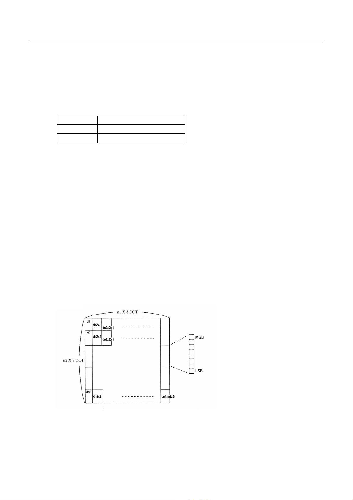
(35) Defining Download Bit Image (GS * n1 n2 Dn)
Code : [1D]h + [2A]h + n1 + n2 Dn
*{1≤ n1 ≤ FF}
{1 ≤ n2 ≤ 48}
{n1 X n2 ≤ 1311} Data is described in Hex code.
CBM-290/291 User’s Manual
Defines downloading bit images of the number of dots specified by n1/n2.
• Thenumbersofdotsaren1x8inhorizontaldirectionandn2x8inverticaldirection.
• Dn indicates bit image data.
• The download bit image thus defined remains effective until redefinition, ESC @ execution, ESC &,
or power OFF takes place.
• A download character and a download bit image cannot be defined simultaneously.
With this command executed, defined content of a download character is cleared.
• Relations between the bit image data and the dot defined are shown below:
37
CITIZEN

(36) Printing Download Bit Image (GS / m)
Code : [1D]h + [2F]h + m
*{0≤ m ≤ 3} Data is described in Hex code.
Prints download bit iamges in a mode specified by m.
• Modes can be selected by m are shown in table for selection with m are shown below.
CBM-290/291 User’s Manual
m MODE NAME DOT DENSITY IN
VERTICAL DIRECTION
DOT DENSITY IN
HORIZONTAL DIRECTION
0 Normal mode 203 DPI 203 DPI
1 Double wide mode 203 DPI 101 DPI
2 Double high mode 101 DPI 203 DPI
3 Double wide/double high mode 101 DPI 101 DPI
• When data exist inside the print buffer, this command is ignored.
• When a download bit image has not been defined, this command is ignored.
• A portion of a download bit image exceeding one line length is not printed.
• A download character and a download bit image cannot be defined simultaneously.
(37) Starting / Ending Macro Definition (GS :)
Code : [1D]h + [3A]h
Specifying starting / ending macro definition. Maximum content available for macro definition is 2048
bytes. A portion exceeding 2048 bytes is not defined.
• Even with ESC @ (initialization of the printer) having been executed, defined content is not cleared.
Therefore, it is possible to include ESC @ into the content of macro definition.
• Normal printing operation is carried out even while in macro definition
(38) Macro Execution (GS ^ n1 n2 n3)
Code : [1D]h + [5E]h + n1 + n2 + n3
*{0≤ n1 ≤ FF}
{0 ≤ n2 ≤ FF}
{0 ≤ 3 ≤ 1} Data is described in Hex code.
Executing contents defined in macro.
• "n1 - n3" indicate as follows:
n1 : The number of times of macro execution
n2 : Waiting time on macro execution
Waiting time of n2 x 100 msec is given for every execution.
n3 : Macro execution mode
n3 Mode
0 Continuous execution
1 Execution by LF SW
38
CITIZEN

CBM-290/291 User’s Manual
Continuous execution : The Macro is executed n1 times continuously at the time intervals
specified by n2.
Execution by FEED SW : After waiting for lapse of time specified by n2, the ERROR LED
flickers and the LF switch is waited to be pressed. When it is pressed,
the macro is executed once. This action is repeated n1 times.
• When this command is received while in macro definition, suspension of macro definition is indicated.
At this time, the defined content is cleared.
• No execution takes place when macro is held undefined or n1=0.
• While in macro execution with n3=1, paper feed with the LF SW is not available.
(39) Data Input Control (ESC = n)
Code : [1B]h + [3D]h + n
*{0≤ n ≤ FF} Data is described in Hex code.
Selecting equipment in which data input from the host is effective.
• Each bit of n indicates as follows:
VALUE
BIT EQUIPMENT 0 1
0 Printer Invalid Valid
1 Not defined
2 Not defined
3 Not defined
4 Not defined
5 Not defined
6 Not defined
7 Not defined
• When the printer has not been selected, this printer abandons all the received data until it is selected
by this command.
• Even when the printer has not been selected, it can become BUSY state through printer operation.
• The initial value of n is "1".
39
CITIZEN

(40) Aligning the characters (ESC a n)
Code : [1b}h + [61]h + n
*{0≤ n ≤ 2} Data is described in Hex code.
All the printed data within one line are aligned in the specified position.
• Depending on n value, positional alignment is carried out as in the table below:
n (Hex) POSITION
0 Left end alignment
1Centering
2 Right end alignment
• This is valid only when n is inputted at the beginning of line.
• The initial value of n is "0".
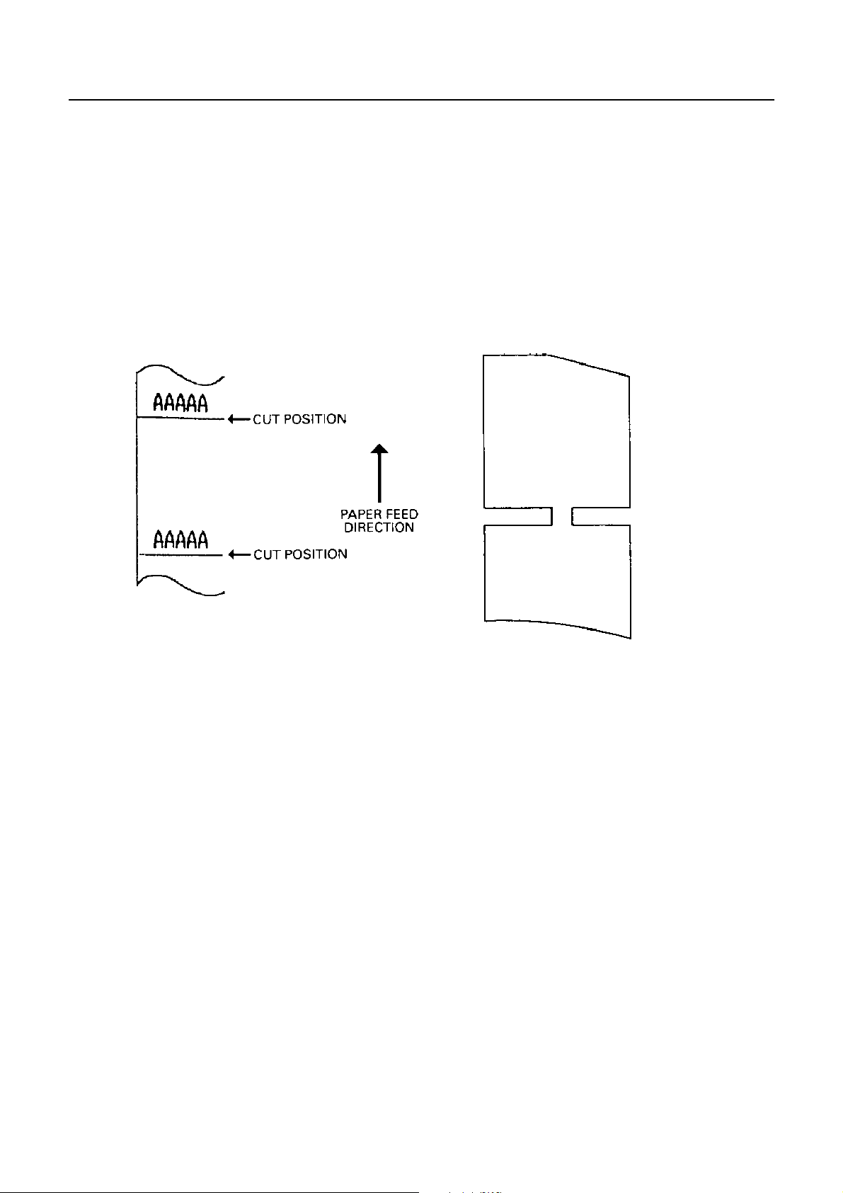
(41) Full Cut (ESC i)
Code : [1B]h + [69]h
Activating auto cutter (Full cut)
CBM-290/291 User’s Manual
• This is valid only when n is inputted at the beginning of line.
• Make sure to feed the paper by 18 mm or more before cutting paper, unless characters remain before
the cutting point.
Print Result Cutting Condition
40
CITIZEN
CBM-290/291 User’s Manual
(42) Partial Cut (ESC m) (In selection of cutter option)
Code : [1B]h + [6D]h
Activating auto cutter unit (Partial cut)
• This is valid only when n is inputted at the beginning of line.
• Make sure to feed the paper by 18 mm or more before cutting paper, unless characters remain before
the cutting point.
Print Result Cutting Condition
41
CITIZEN

10. Character Table
CBM-290/291 User’s Manual
10.1 International
CITIZEN 54
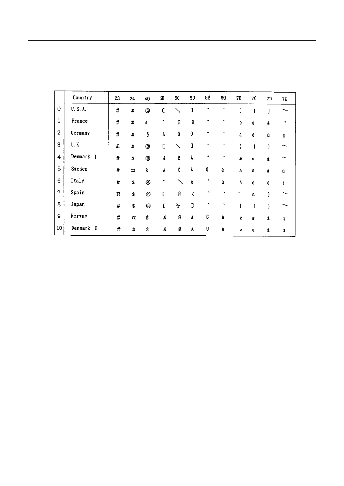
10.2 International Character Code Table
CBM-290/291 User’s Manual
43
CITIZEN
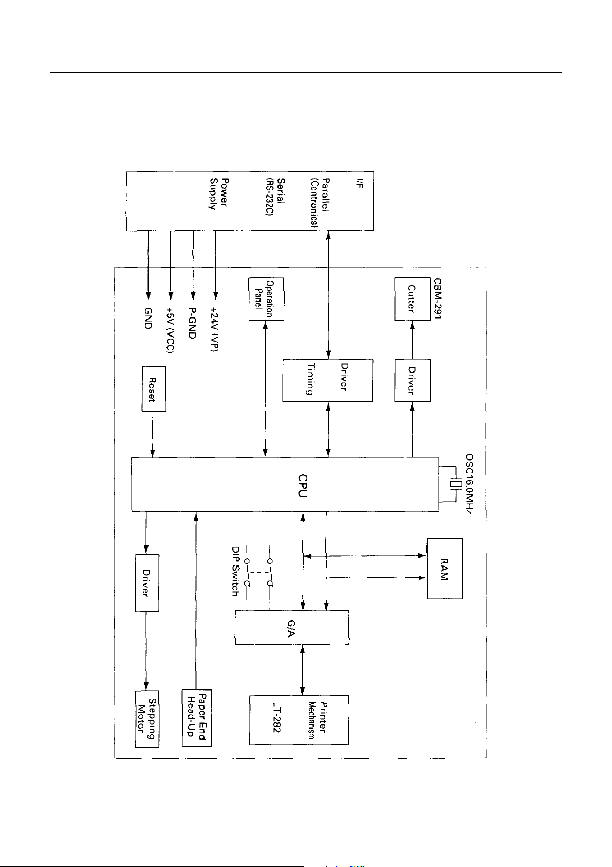
Appendix 1. Block Diagram
CBM-290/291 User’s Manual
44
CITIZEN

Appendix 2. Outer Appearance
CBM-290/291 User’s Manual
45
CITIZEN

1.08E-0605 Printed in Japan
 Loading...