

Cisco WS-C5509, ASA5520-BUN-K9 - ASA 5520 Appliance, ASA5550-BUN-K9 - ASA 5550 Firewall Edition Bundle, ASA 5510, ASA 5520 Hardware Installation Manual
...Page 1

Cisco ASA 5500 Series Hardware
Installation Guide
For the ASA 5510, ASA 5520, ASA 5540, and ASA 5550
Americas Headquarters
Cisco Systems, Inc.
170 West Tasman Drive
San Jose, CA 95134-1706
USA
http://www.cisco.com
Tel: 408 526-4000
800 553-NETS (6387)
Fax: 408 527-0883
Customer Order Number: 78-17989-01
Text Part Number: 78-17989-01
Page 2

THE SPECIFICATIONS AND INFORMATION REGARDING THE PRODUCTS IN THIS MANUAL ARE SUBJECT TO CHANGE WITHOUT NOTICE. ALL
STATEMENTS, INFORMATION, AND RECOMMENDATIONS IN THIS MANUAL ARE BELIEVED TO BE ACCURATE BUT ARE PRESENTED WITHOUT
WARRANTY OF ANY KIND, EXPRESS OR IMPLIED. USERS MUST TAKE FULL RESPONSIBILITY FOR THEIR APPLICATION OF ANY PRODUCTS.
THE SOFTWARE LICENSE AND LIMITED WARRANTY FOR THE ACCOMPANYING PRODUCT ARE SET FORTH IN THE INFORMATION PACKET THAT
SHIPPED WITH THE PRODUCT AND ARE INCORPORATED HEREIN BY THIS REFERENCE. IF YOU ARE UNABLE TO LOCATE THE SOFTWARE LICENSE
OR LIMITED WARRANTY, CONTACT YOUR CISCO REPRESENTATIVE FOR A COPY.
The following inform ation is for FCC compliance of Class A devices: This equipment has been tested and found to comply with the limits for a Class A digital device, pursuant
to part 15 of the FCC rules. These limits are designed to provide reasonable protection against harmful interference when the equipment is operated in a commercial
environment. This equipment generates, uses, and can radiate radio-frequency energy and, if not installed and used in accordance with the instruction manual, may cause
harmful interference to radio communications. Operation of this equipment in a residential area is likely to cause harmful interference, in which case users will be required
to correct the interference at their own expense.
The following information is for FCC compliance of Class B devices: The equipment described in this manual generates and may radiate radio-frequency energy. If it is not
installed in accordance with Cisco’s installation instructions, it may cause interference with radio and television reception. This equipment has been tested and found to
comply with the limits for a Class B digital device in accordance with the specifications in part 15 of the FCC rules. These specifications are designed to provide reasonable
protection against such interference in a residential installation. However, there is no guarantee that interference will not occur in a particular installation.
Modifying the equipment without Cisco’s written authorization may result in the equipment no longer complying with FCC requirements for Class A or Class B digital
devices. In that event, your right to use the equipment may be limited by FCC regulations, and you may be required to correct any interference to radio or television
communications at your own expense.
You can determine whether your equipment is causing interference by turning it off. If the interference stops, it was probably caused by the Cisco equipment or one of its
peripheral devices. If the equipment causes interference to radio or television reception, try to correct the interference by using one or more of the following measures:
• Turn the television or radio antenna until the interference stops.
• Move the equipment to one side or the other of the television or radio.
• Move the equipment farther away from the television or radio.
• Plug the equipment into an outlet that is on a different circuit from the television or radio. (That is, make certain the equipment and the television or radio are on circuits
controlled by different circuit breakers or fuses.)
Modifications to this product not authorized by Cisco Systems, Inc. could void the FCC approval and negate your authority to operate the product.
The Cisco implementation of TCP header compression is an adaptation of a program developed by the University of California, Berkeley (UCB) as part of UCB’s public
domain version of the UNIX operating system. All rights reserved. Copyright © 1981, Regents of the University of California.
NOTWITHSTANDING ANY OTHER WARRANTY HEREIN, ALL DOCUMENT FILES AND SOFTWARE OF THESE SUPPLIERS ARE PROVIDED “AS IS” WITH
ALL FAULTS. CISCO AND THE ABOVE-NAMED SUPPLIERS DISCLAIM ALL WARRANTIES, EXPRESSED OR IMPLIED, INCLUDING, WITHOUT
LIMITATION, THOSE OF MERCHANTABILITY, FITNESS FOR A PARTICULAR PURPOSE AND NONINFRINGEMENT OR ARISING FROM A COURSE OF
DEALING, USAGE, OR TRADE PRACTICE.
IN NO EVENT SHALL CISCO OR ITS SUPPLIERS BE LIABLE FOR ANY INDIRECT, SPECIAL, CONSEQUENTIAL, OR INCIDENTAL DAMAGES, INCLUDING,
WITHOUT LIMITATION, LOST PROFITS OR LOSS OR DAMAGE TO DATA ARISING OUT OF THE USE OR INABILITY TO USE THIS MANUAL, EVEN IF CISCO
OR ITS SUPPLIERS HAVE BEEN ADVISED OF THE POSSIBILITY OF SUCH DAMAGES.
Cisco and the Cisco logo are trademarks or registered trademarks of Cisco and/or its affiliates in the U.S. and other countries. To view a list of Cisco trademarks, go to this
URL: www.cisco.com/go/trademarks. Third-party trademarks mentioned are the property of their respective owners. The use of the word partner does not imply a partnership
relationship between Cisco and any other company. (1110R)
Cisco ASA 5500 Series Hardware Installation Guide
©2009 Cisco Systems, Inc. All rights reserved.
Page 3

CONTENTS
About This Guide v
Document Objectives v
Audience v
Document Organization v
Document Conventions vi
Installation Warnings vi
Where to Find Safety and Warning Information x
Obtaining Documentation and Submitting a Service Request 1-x
CHAPTER
CHAPTER
CHAPTER
1 Overview 1-1
Product Overview 1-2
Memory Requirements 1-5
2 Preparing for Installation 2-1
Overview 2-1
Installation Overview 2-1
Safety Recommendations 2-2
Maintaining Safety with Electricity 2-2
Preventing Electrostatic Discharge Damage 2-3
General Site Requirements 2-4
Site Environment 2-4
Preventive Site Configuration 2-4
Power Supply Considerations 2-4
Configuring Equipment Racks 2-6
3 Installing the Adaptive Security Appliance 3-1
Installing the Adaptive Security Appliance 3-1
Rack-Mounting the Chassis 3-2
Setting the Chassis on a Desktop 3-3
Connecting the Interface Cables 3-4
CHAPTER
4 Maintenance and Upgrade Procedures 4-1
Removing and Replacing the Chassis Cover 4-1
78-17989-01
Cisco ASA 5500 Series Hardware Installation Guide
1
Page 4

Contents
Removing the Chassis Cover 4-1
Replacing the Chassis Cover 4-2
Working in an ESD Environment 4-3
Removing and Replacing a Lithium Battery in the SSM 4-4
Removing and Replacing the Power Supply 4-4
Removing the AC Power Supply 4-4
Replacing the AC Power Supply 4-6
Installing the DC Model 4-7
Removing and Replacing the CompactFlash 4-10
Removing the System CompactFlash 4-10
Replacing the System CompactFlash 4-11
Removing the User CompactFlash 4-12
Replacing the User CompactFlash 4-12
Installing and Replacing the 4GE SSM 4-13
Overview 4-13
Installing the 4GE SSM 4-14
Replacing the 4GE SSM 4-15
Installing and Removing the SFP Modules 4-15
SFP Module 4-16
Installing the SFP Module 4-17
Removing the SFP Module 4-18
APPENDIX
I
NDEX
Installing and Replacing the Intelligent SSM 4-19
Overview 4-20
Installing and Replacing the AIP/CSC SSM 4-21
Installing the AIP/CSC SSM 4-21
Replacing the AIP/CSC SSM 4-22
Upgrading Memory for the Cisco ASA 5510 4-22
Removing the DIMM 4-23
Installing the DIMM 4-25
4-26
1 Cable Pinouts 1-1
10/100/1000BaseT Connectors 1-1
Console Port (RJ-45) 1-2
RJ-45 to DB-9 1-4
MGMT 10/100/1000 Ethernet Port 1-4
Gigabit and Fibre Channel Ports 1-5
Cisco ASA 5500 Series Hardware Installation Guide
2
78-17989-01
Page 5

About This Guide
This preface includes the following sections:
• Document Objectives, page 3
• Audience, page 3
• Document Organization, page 3
• Document Conventions, page 4
• Installation Warnings, page 4
• Obtaining Documentation and Submitting a Service Request, page 8
Document Objectives
This guide describes how to perform installation and maintenance procedures on the
Cisco ASA 5500 Series Adaptive Security Appliances. The information in this guide applies to the
following Cisco ASA 5500 Series Adaptive Security Appliance models: Cisco ASA 5510,
Cisco ASA 5520, Cisco ASA 5540, and Cisco ASA 5550. In this guide, references to
"Cisco ASA 5500 Series Adaptive Security Appliance" and "adaptive security appliance" apply to all
models unless specifically noted otherwise.
Audience
This guide is for network administrators who perform any of the following tasks:
• Managing network security
• Installing and configuring firewalls
• Managing default and static routes, and TCP and UDP services
Document Organization
This guide includes the following chapters and appendices:
• Chapter 1, “Overview” describes the product and the memory requirements.
• Chapter 2, “Preparing for Installation,” describes the steps to follow before installing new hardware
or performing hardware upgrades.
78-17989-01
Cisco ASA 5500 Series Hardware Installation Guide
3
Page 6

• Chapter 3, “Installing the Adaptive Security Appliance,”describes how to install the chassis on the
wall or rack and how to connect the interface cables on the adaptive security appliance.
• Chapter 4, “Maintenance and Upgrade Procedures,” describes how to remove and replace the chassis
cover, the lithium battery in the SSM, the power supply, the CompactFlash, and the SSMs.
• Appendix 1, “Cable Pinouts,” describes the cable pinouts.
Document Conventions
Command descriptions use these conventions:
• Braces ({ }) indicate a required choice.
• Square brackets ([ ]) indicate optional elements.
• Vertical bars (|) separate alternative, mutually exclusive elements.
• Boldface indicates commands and keywords that are entered literally as shown.
• Italics indicate arguments for which you supply values.
Examples use these conventions:
• Examples depict screen displays and the command line in screen font.
About This Guide
• Information you need to enter in examples is shown in boldface screen font.
• Variables for which you must supply a value are shown in
Graphical user interface examples uses these conventions:
• Boldface indicates buttons and menu items.
• Selecting a menu item (or pane) is indicated by the following convention:
Choose Start > Settings > Control Panel.
Note Means reader take note. Notes contain helpful suggestions or references to material not covered in the
manual.
Installation Warnings
Be sure to read the Regulatory Compliance and Safety Information for the Cisco ASA 5500 Series document
that accompanied this device before installing the chassis. This document contains important safety
information. This section includes the following warnings:
• Power Supply Disconnection Warning, page 5
• Jewelry Removal Warning, page 5
• Wrist Strap Warning, page 5
italic screen
font.
• Work During Lightning Activity Warning, page 5
• Installation Instructions Warning, page 5
• Chassis Warning for Rack-Mounting and Servicing, page 6
• Short-Circuit Protection Warning, page 6
• SELV Circuit Warning, page 6
Cisco ASA 5500 Series Hardware Installation Guide
4
78-17989-01
Page 7
About This Guide
• Ground Conductor Warning, page 6
• Blank Faceplates and Cover Panels Warning, page 6
• Product Disposal Warning, page 6
• Short-Circuit Protection Warning, page 7
• Compliance with Local and National Electrical Codes Warning, page 7
• DC Power Connection Warning, page 7
• AC Power Disconnection Warning, page 7
• TN Power Warning, page 7
• 48 VDC Power System, page 7
• Multiple Power Cord, page 7
• Circuit Breaker (15A) Warning, page 7
• Grounded Equipment Warning, page 8
• Safety Cover Requirement, page 8
• Faceplates and Cover Panel Requirement, page 8
Power Supply Disconnection Warning
Warning
Before working on a chassis or working near power supplies, unplug the power cord on AC units;
disconnect the power at the circuit breaker on DC units.
Jewelry Removal Warning
Warning
Before working on equipment that is connected to power lines, remove jewelry (including rings,
necklaces, and watches). Metal objects will heat up when connected to power and ground and can
cause serious burns or weld the metal object to the terminals.
Wrist Strap Warning
Warning
During this procedure, wear grounding wrist straps to avoid ESD damage to the card. Do not directly
touch the backplane with your hand or any metal tool, or you could shock yourself.
Work During Lightning Activity Warning
Statement 12
Statement 43
Statement 94
Warning
Do not work on the system or connect or disconnect cables during periods of lightning activity.
Statement 1001
Installation Instructions Warning
Warning
78-17989-01
Read the installation instructions before connecting the system to the power source.
Statement 1004
Cisco ASA 5500 Series Hardware Installation Guide
5
Page 8
Chassis Warning for Rack-Mounting and Servicing
About This Guide
Warning
To prevent bodily injury when mounting or servicing this unit in a rack, you must take special
precautions to ensure that the system remains stable. The following guidelines are provided to
ensure your safety:
rack.When mounting this unit in a partially filled rack, load the rack from the bottom to the top with the
heaviest component at the bottom of the rack.If the rack is provided with stabilizing devices, install the
stabilizers before mounting or servicing the unit in the rack.
Short-Circuit Protection Warning
Warning
This product requires short-circuit (overcurrent) protection, to be provided as part of the building
installation. Install only in accordance with national and local wiring regulations.
SELV Circuit Warning
Warning
To avoid electric shock, do not connect safety extra-low voltage (SELV) circuits to telephone-network
voltage (TNV) circuits. LAN ports contain SELV circuits, and WAN ports contain TNV circuits. Some
LAN and WAN ports both use RJ-45 connectors. Use caution when connecting cables.
Ground Conductor Warning
This unit should be mounted at the bottom of the rack if it is the only unit in the
Statement 1006
Statement 1045
Statement 1021
Warning
This equipment must be grounded. Never defeat the ground conductor or operate the equipment in the
absence of a suitably installed ground conductor. Contact the appropriate electrical inspection
authority or an electrician if you are uncertain that suitable grounding is available.
Blank Faceplates and Cover Panels Warning
Warning
Blank faceplates and cover panels serve three important functions: they prevent exposure to
hazardous voltages and currents inside the chassis; they contain electromagnetic interference (EMI)
that might disrupt other equipment; and they direct the flow of cooling air through the chassis. Do not
operate the system unless all cards, faceplates, front covers, and rear covers are in place.
1029
Product Disposal Warning
Warning
Ultimate disposal of this product should be handled according to all national laws and regulations.
Statement 1040
Statement 1024
Statement
Cisco ASA 5500 Series Hardware Installation Guide
6
78-17989-01
Page 9
About This Guide
Short-Circuit Protection Warning
Warning
This product requires short-circuit (overcurrent) protection, to be provided as part of the building
installation. Install only in accordance with national and local wiring regulations.
Compliance with Local and National Electrical Codes Warning
Warning
Installation of the equipment must comply with local and national electrical codes.
DC Power Connection Warning
Warning
After wiring the DC power supply, remove the tape from the circuit breaker switch handle and
reinstate power by moving the handle of the circuit breaker to the ON position.
AC Power Disconnection Warning
Warning
Before working on a chassis or working near power supplies, unplug the power cord on AC units.
Statement 246
TN Power Warning
Statement 1045
Statement 1074
Statement 8
Warning
The device is designed to work with TN power systems.
48 VDC Power System
Warning
The customer 48 volt power system must provide reinforced insulation between the primary AC power
and the 48 VDC output.
Multiple Power Cord
Warning
This unit has more than one power cord. To reduce the risk of electric shock when servicing a unit,
disconnect the power cord of the power strip that the unit is plugged into.
Circuit Breaker (15A) Warning
Warning
This product relies on the building’s installation for short-circuit (overcurrent) protection. Ensure that
a fuse or circuit breaker no larger than 120 VAC, 15A U.S. (240 VAC, 10A international) is used on the
phase conductors (all current-carrying conductors).
Statement 19
Statement 128
Statement 137
Statement 13
78-17989-01
Cisco ASA 5500 Series Hardware Installation Guide
7
Page 10
Grounded Equipment Warning
About This Guide
Warning
This equipment is intended to be grounded. Ensure that the host is connected to earth ground during
normal use.
Statement 39
Safety Cover Requirement
Warning
The safety cover is an integral part of the product. Do not operate the unit without the safety cover
installed. Operating the unit without the cover in place will invalidate the safety approvals and pose
a risk of fire and electrical hazards.
Statement 117
Faceplates and Cover Panel Requirement
Warning
Blank faceplates and cover panels serve three important functions: they prevent exposure to
hazardous voltages and currents inside the chassis; they contain electromagnetic interference (EMI)
that might disrupt other equipment; and they direct the flow of cooling air through the chassis. Do not
operate the system unless all cards, faceplates, front covers, and rear covers are in place.
142
Where to Find Safety and Warning Information
For safety and warning information, see the Regulatory Compliance and Safety Information for the
Cisco ASA 5500 Series document that accompanied the product. This document describes the
international agency compliance and safety information for the Cisco ASA 5500 Series Adaptive
Security Appliance. It also includes translations of the safety warnings.
Statement
Obtaining Documentation and Submitting a Service Request
For information on obtaining documentation, submitting a service request, and gathering additional
information, see the monthly What’s New in Cisco Product Documentation, which also lists all new and
revised Cisco technical documentation, at:
http://www.cisco.com/en/US/docs/general/whatsnew/whatsnew.html
Subscribe to the What’s New in Cisco Product Documentation as an RSS feed and set content to be
delivered directly to your desktop using a reader application. The RSS feeds are a free service. Cisco currently
supports RSS Version 2.0.
Cisco ASA 5500 Series Hardware Installation Guide
8
78-17989-01
Page 11

CHA PTER
1
Overview
Read through the entire guide before beginning any of the procedures in this book.
Warning
Caution Read the safety warnings in the Regulatory Compliance and Safety Information for the Cisco ASA 5500
Note The illustrations in this chapter show the Cisco ASA 5540 adaptive security appliance. The
Only trained and qualified personnel should install, replace, or service this equipment.
Series and follow proper safety procedures when performing these steps.
This chapter describes the product and the memory requirements, and includes the following topics:
• Product Overview, page 1-2
• Memory Requirements, page 1-5
Cisco ASA 5510 and Cisco ASA 5520 adaptive security appliance look identical, containing the same
back panel features and indicators. The Cisco ASA 5550 has a fixed configuration with an embedded 4GE
slot as shown in Figure 1-3.
Statement 49
OL-10089-01
Cisco ASA 5500 Series Hardware Installation Guide
1-1
Page 12
Product Overview
119638
POWER STATUS
FLASH
ACTIVE
VPN
CISCO ASA 5540
SERIES
Adaptive Security Appliance
1
2
3
4
5
119572
LINK SPD
3
LINK SPD2LINK SPD1LINK SPD
0
MGMT
USB2
USB1
FLASH
CONSOLE
AUX
POWER
STATUS
FLASH
1
9
2
3
4
5
11
13
14
7
6
8 10 12
VPN
ACTIVE
Product Overview
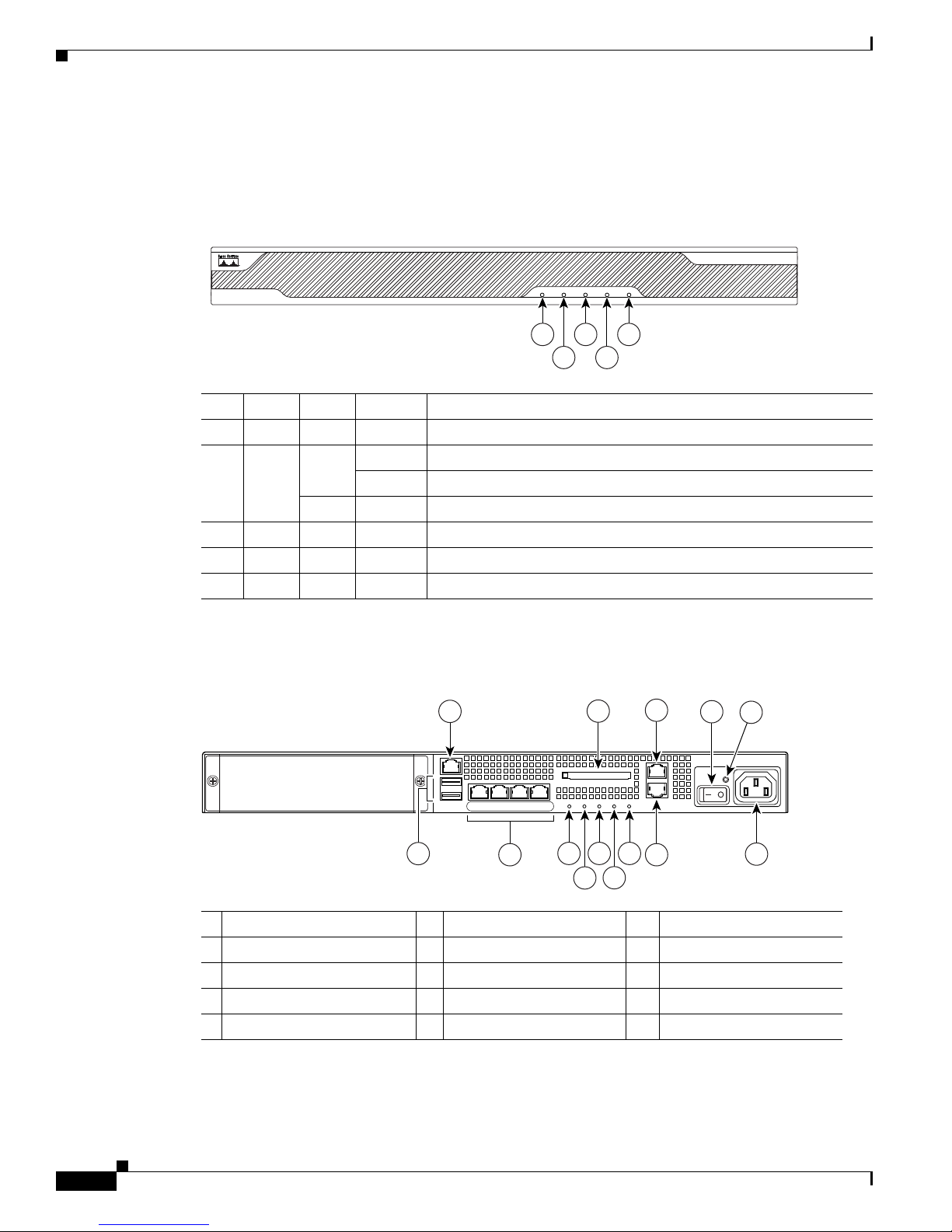
This section describes the front and rear panels. Figure 1-1 shows the front panel LEDs.
Figure 1-1 Front Panel LEDs
LED Color State Description
1 Power Green On The system has power.
2 Status Green Flashing The power-up diagnostics are running or the system is booting.
3 Active Green Flashing There is network activity.
4 VPN Green Solid VPN tunnel is established.
5 Flash Green Solid The CompactFlash is being accessed.
Chapter 1 Overview
Solid The system has passed power-up diagnostics.
Amber Solid The power-up diagnostics have failed.
Figure 1-2 shows the rear panel.
Figure 1-2 Rear Panel LEDs and Ports (AC Power Supply Model Shown)
1 Management port
2 External CompactFlash slot 7 Network interfaces
3 Serial Console port 8 Power indicator LED 13 AUX port
4 Power switch 9 Status indicator LED 14 Power connector
5 Power indicator LED 10 Active LED
1. The management 0/0 interface is a Fast Ethernet interface designed for management traffic only.
2. Not supported at this time.
3. GigabitEthernet interfaces, from right to left, GigabitEthernet 0/0, GigabitEthernet 0/1, GigabitEthernet 0/2, and
GigabitEthernet 0/3.
Cisco ASA 5500 Series Hardware Installation Guide
1-2
1
6 USB 2.0 interfaces
2
3
11 VPN LED
12 Flash LED
4
OL-10089-01
Page 13
Chapter 1 Overview
153642
LINK SPD2LINK SPD1LINK SPD
0
LINK SPD
3
MGMT
USB2
USB1
FLASH
CONSOLE
AUX
POWER
STATUS
FLASH
10
13
18
19
20
21
15
17
22
11
12 14 16
VPN
ACTIVE
P
W
R
LNK
SPD0123
9
4
1
6
5
2 3
7
8
Product Overview
4. The RJ-45 Auxiliary port (labeled AUX on the chassis) is reserved for internal use at Cisco. The port is not functional
in shipping versions of the chassis; therefore, customers cannot connect to this port to run the adaptive security
appliance CLI.
For more information about the Management port, see themanagement only command in the
Cisco Security Appliance Command Reference.
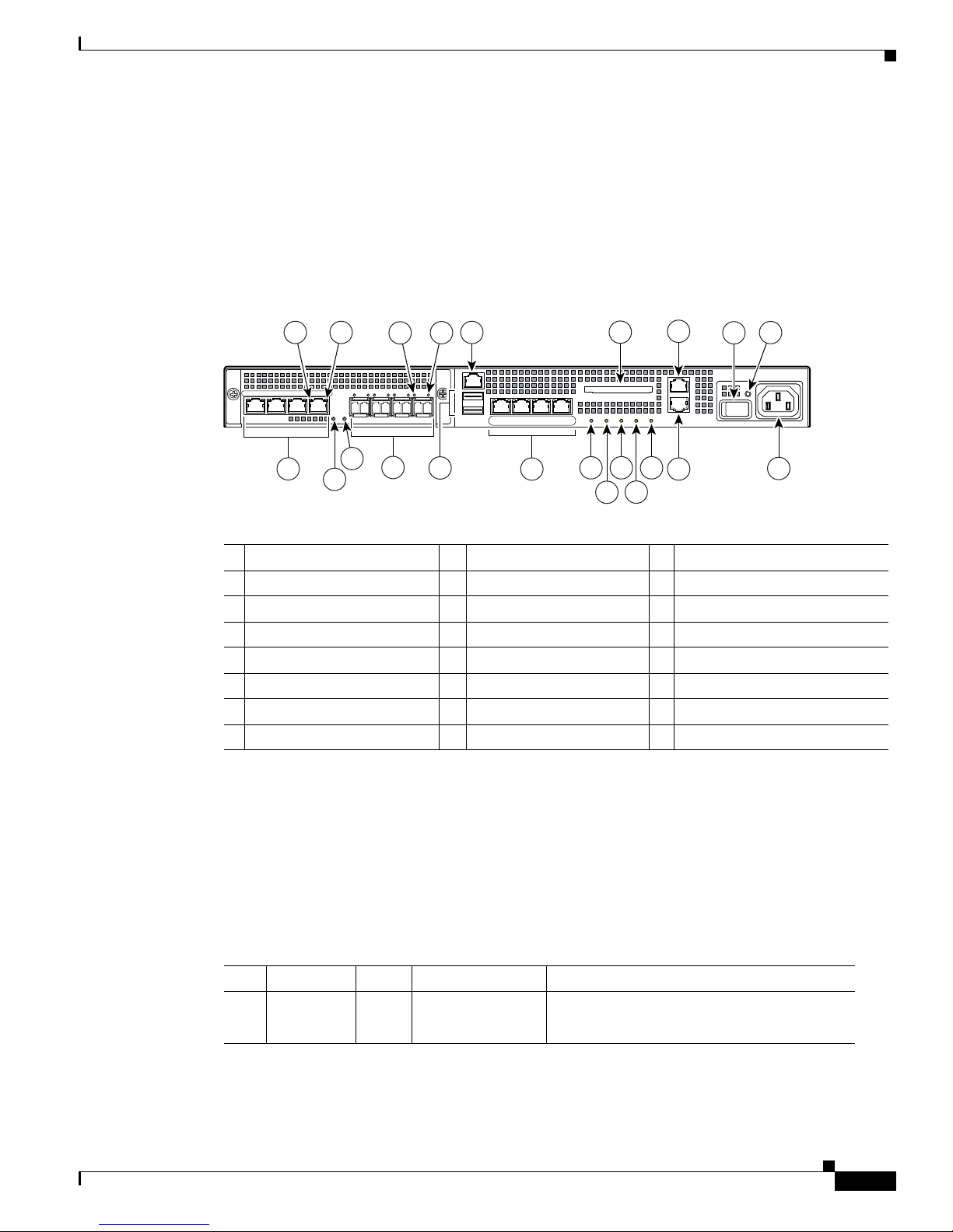
The Cisco ASA 5550 has a fixed configuration with an embedded 4GE slot as shown in Figure 1-3.
Figure 1-3 Rear Panel LEDs and Ports for the Cisco ASA 5550
1 RJ-45 ports
1
9 USB 2.0 interfaces
2 RJ-45 Link LED 10 Management port
3 RJ-45 Speed LED 11 Network interfaces
2
3
4
17 AUX port
18 External CompactFlash slot
19 Serial Console port
4 Power LED 12 Power indicator LED 20 Power switch
5 Status LED 13 Status indicator LED 21 Power indicator LED
6 SFP ports
5
14 Active LED 22 Power connector
7 SFP Link LED 15 VPN LED
8 SFP Speed LED 16 Flash LED
1. GigabitEthernet ports, from right to left, GigabitEthernet 1/0, GigabitEthernet 1/1, GigabitEthernet 1/2, and
GigabitEthernet 1/3
2. Not supported at this time.
3. The management 0/0 interface is a Fast Ethernet interface designed for management traffic only.
4. GigabitEthernet interfaces, from right to left, GigabitEthernet 0/0, GigabitEthernet 0/1, GigabitEthernet 0/2, and
GigabitEthernet 0/3.
5. SFP ports, from right to left, GigabitEthernet 1/0, GigabitEthernet 1/1, GigabitEthernet 1/2, and GigabitEthernet 1/3
Table 1-1 describes the 4GE SSM LEDs.
Table 1-1 4GE SSM LEDs for the Cisco ASA 5550
LED Color State Description
2, 7 LINK Green Solid
There is an Ethernet link.
OL-10089-01
Flashing
There is Ethernet activity.
Cisco ASA 5500 Series Hardware Installation Guide
1-3
Page 14
Product Overview
126917
USB2
USB1
LNK SPD
3
LNK SPD2LNK SPD1LNK SPD
0
MGMT
21
Table 1-1 4GE SSM LEDs (continued) for the Cisco ASA 5550
LED Color State Description
3, 8 SPEED Off
Green
10 MB
100 MB
There is no network activity.
There is network activity at 100 Mbps.
Chapter 1 Overview
Amber
1000 MB (GigE)
There is network activity at 1000 Mbps.
4 POWER Green On The system has power.
5 STATUS Green
Green
Amber
Flashing
Solid
Solid
The system is booting.
The system booted correctly.
The system diagnostics failed.
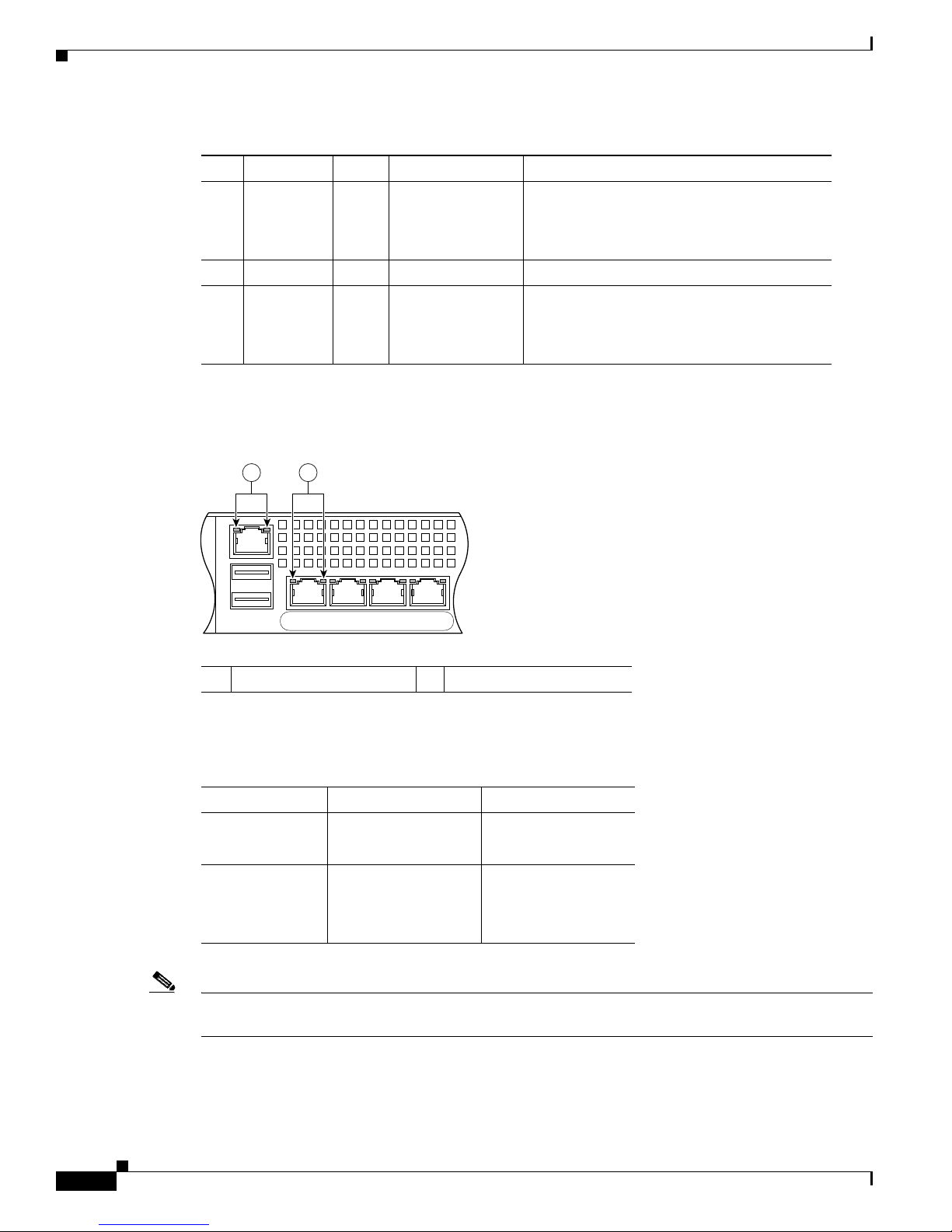
Figure 1-4 shows the adaptive security appliance rear panel LEDs.
Figure 1-4 Rear Panel Link and Speed Indicator LEDs
1 MGMT indicator LEDs 2 Network interface LEDs
1-4
Table 1-2 lists the rear MGMT and Network interface LEDs.
Table 1-2 Link and Speed LEDs
Indicator Color Description
Left side Solid green
Green flashing
Right side Not lit
Green
Amber
Note The Cisco ASA 5510 adaptive security appliance supports only 10/100BaseTX. The Cisco ASA 5520
Physical link
Network activity
10 Mbps
100 Mbps
1000 Mbps
and the Cisco ASA 5540 support 1000BaseT.
Cisco ASA 5500 Series Hardware Installation Guide
OL-10089-01
Page 15
Chapter 1 Overview
Memory Requirements
Table 1-3 lists the CPU and the memory specifications for each model.
Table 1-3 CPU and Memory Specifications
ASA Model CPU Default DRAM Memory Default Internal Flash Memory
Cisco ASA 5510 1.6 GHz Celeron 256 MB 512MB
Cisco ASA 5520 2.0 GHz Celeron 512 MB 512MB
Cisco ASA 5540 2.0 GHz Pentium 4 1024 MB 512MB
Cisco ASA 5550 3.0 GHz Pentium 4 4096 MB 512MB
In a failover configuration, the two units must have the same hardware configuration. They must be the
same model, have the same number and types of interfaces, and the same amount of RAM.
Note The two units do not have to have the same size Flash memory. If using units with different Flash
memory sizes in your failover configuration, make sure the unit with the smaller Flash memory has
enough space to accommodate the software image files and the configuration files. If it does not,
configuration synchronization from the unit with the larger Flash memory to the unit with the smaller
Flash memory will fail.
Memory Requirements
For more information, see the Cisco Security Appliance Command Line Configuration Guide.
Memory Requirements for Software Version 8.3 and Later
For information on memory requirements for the adaptive security appliance for software Version 8.3 or
later, go to:
http://www.cisco.com/en/US/prod/collateral/vpndevc/ps6032/ps6094/ps6120/product_bulletin_c25-58
6414.html
OL-10089-01
Cisco ASA 5500 Series Hardware Installation Guide
1-5
Page 16

Memory Requirements
Chapter 1 Overview
Cisco ASA 5500 Series Hardware Installation Guide
1-6
OL-10089-01
Page 17

Overview
CHA PTER
2
Preparing for Installation
The information in this guide applies to the following Cisco ASA 5500 series Adaptive Security
Appliance models: Cisco ASA 5510, Cisco ASA 5520, Cisco ASA 5540, and Cisco ASA 5550. In this
guide, references to “Cisco ASA 5500 series Adaptive Security Appliance” and “adaptive security
appliance” apply to all models unless specifically noted otherwise.
This chapter describes the steps to follow before installing new hardware or performing hardware
upgrades, and includes the following sections:
• Overview, page 2-1
• Installation Overview, page 2-1
• Safety Recommendations, page 2-2
• General Site Requirements, page 2-4
The adaptive security appliance delivers unprecedented levels of defense against threats to the network
with deeper web inspection and flow-specific analysis, improved secure connectivity via end-point
security posture validation, and voice and video over VPN support. It also provides enhanced support
for intelligent information networks through improved network integration, resiliency, and scalability.
The adaptive security appliance software combines firewall, VPN concentrator, and intrusion prevention
software functionality into one software image. Previously, these functions were available in three
separate devices, each with its own software and hardware. Combining the functionality into just one
software image provides significant improvements in the available features.
Additionally, the Cisco ASA 5500 series Adaptive Security Appliance software supports Adaptive
Security Device Manager. ASDM is a browser-based, Java applet used to configure and monitor the
software on the adaptive security appliances. ASDM is loaded from the adaptive adaptive security
appliance, then used to configure, monitor, and manage the device.
Installation Overview
To prepare for the installation of the chassis, perform the following steps:
Step 1 Review the safety precautions outlined in the Regulatory Compliance and Safety Information for the
Cisco ASA 5500 Series document.
78-17989-01
Cisco ASA 5500 Series Hardware Installation Guide
2-1
Page 18
Safety Recommendations
Step 2 Read the release notes for the respective software version.
Step 3 Unpack the chassis. An accessory kit ships with the chassis and includes the following items:
documentation, a product CD, a power cord (AC models only), two RJ-45 Ethernet cables, one RJ-45 to
DB-9 console cable, a rack-mounting kit, and four self-adhesive feet (for desktop mounting).
Step 4 Place the chassis on a stable work surface.
Safety Recommendations
Use the following guidelines and the information in the following sections to help ensure your safety and
protect the adaptive security appliance. The list of guidelines may not address all potentially hazardous
situations in your working environment, so be alert and exercise good judgement at all times.
Note If you need to remove the chassis cover to install a hardware component, such as additional memory or
an interface card, doing so does not affect your Cisco warranty. Upgrading the adaptive security
appliance does not require any special tools and does not create any radio frequency leaks.
Chapter 2 Preparing for Installation
The safety guidelines are as follows:
• Keep the chassis area clear and dust-free before, during and after installation.
• Keep tools away from walk areas where you and others could fall over them.
• Do not wear loose clothing or jewelry, such as earrings, bracelets, or chains, that could get caught
in the chassis.
• Wear safety glasses if you are working under any conditions that might be hazardous to your eyes.
• Do not perform any action that creates a potential hazard to people or makes the equipment unsafe.
• Never attempt to lift an object that is too heavy for one person to handle.
This section includes the following topics:
• Maintaining Safety with Electricity, page 2-2
• Preventing Electrostatic Discharge Damage, page 2-3
Maintaining Safety with Electricity
Warning
Before working on a chassis or working near power supplies, unplug the power cord on AC units;
disconnect the power at the circuit breaker on DC units.
Follow these guidelines when working on equipment powered by electricity:
• Before beginning procedures that require access to the interior of the chassis, locate the emergency
power-off switch for the room in which you are working. Then, if an electrical accident occurs, you
can act quickly to turn off the power.
Statement 12
• Do not work alone if potentially hazardous conditions exist anywhere in your work space.
• Never assume that power is disconnected from a circuit; always check the circuit.
Cisco ASA 5500 Series Hardware Installation Guide
2-2
78-17989-01
Page 19

Chapter 2 Preparing for Installation
• Look carefully for possible hazards in your work area, such as moist floors, ungrounded power
extension cables, frayed power cords, and missing safety grounds.
• If an electrical accident occurs, proceed as follows:
–
–
–
–
• Use the adaptive security appliance chassis within its marked electrical ratings and product usage
instructions.
• Install the adaptive security appliance in compliance with local and national electrical codes as listed
in the Regulatory Compliance and Safety Information for the Cisco ASA 5500 Series document.
• The adaptive security appliance models equipped with AC-input power supplies are shipped with a
3-wire electrical cord with a grounding-type plug that fits only a grounding-type power outlet. Do
not circumvent this safety feature. Equipment grounding should comply with local and national
electrical codes.
Safety Recommendations
Use caution; do not become a victim yourself.
Disconnect power from the system.
If possible, send another person to get medical aid. Otherwise, assess the condition of the victim
and then call for help.
Determine if the person needs rescue breathing or external cardiac compressions; then take
appropriate action.
• The adaptive security appliance models equipped with DC-input power supplies must be terminated
with the DC input wiring on a DC source capable of supplying at least 15 amps. A 15-amp circuit
breaker is required at the 48 VDC facility power source. An easily accessible disconnect device
should be incorporated into the facility wiring. Be sure to connect the grounding wire conduit to a
solid earth ground. We recommend that you use a closed loop ring to terminate the ground conductor
at the ground stud. The DC return connection to this system is to remain isolated from the system
frame and chassis.
Other DC power guidelines are listed in the Regulatory Compliance and Safety Information for the
Cisco ASA 5500 Series document.
Preventing Electrostatic Discharge Damage
Electrostatic discharge (ESD) can damage equipment and impair electrical circuitry. ESD damage occurs
when electronic components are improperly handled and can result in complete or intermittent failures.
• Always follow ESD-prevention procedures when removing and replacing components. Ensure that
the chassis is electrically connected to earth ground. Wear an ESD-preventive wrist strap, ensuring
that it makes good skin contact. Connect the grounding clip to an unpainted surface of the chassis
frame to safely ground ESD voltages. To properly guard against ESD damage and shocks, the wrist
strap and cord must operate effectively. If no wrist strap is available, ground yourself by touching
the metal part of the chassis.
• For safety, periodically check the resistance value of the antistatic strap, which should be between
1 and 10 megohms (Mohms).
78-17989-01
Cisco ASA 5500 Series Hardware Installation Guide
2-3
Page 20

General Site Requirements
General Site Requirements
The topics in this section describe the requirements your site must meet for safe installation and
operation of your system. Ensure that your site is properly prepared before beginning installation.
This section includes the following topics:
• Site Environment, page 2-4
• Preventive Site Configuration, page 2-4
• Power Supply Considerations, page 2-4
• Configuring Equipment Racks, page 2-6
Site Environment
Place the chassis on a desktop or mount it on a rack. The location of the chassis and the layout of the
equipment rack or wiring room are extremely important for proper system operation. Equipment placed
too close together, inadequate ventilation, and inaccessible panels can cause system malfunctions and
shutdowns, and can make the chassis maintenance difficult.
Chapter 2 Preparing for Installation
For information on physical specifications, see table 7 at the following url:
http://www.cisco.com/en/US/prod/collateral/vpndevc/ps6032/ps6094/ps6120/product_data_sheet0900a
ecd802930c5.html.
When planning the site layout and equipment locations, keep in mind the precautions described in the
next section “Preventive Site Configuration, page 2-4,” to help avoid equipment failures and reduce the
possibility of environmentally caused shutdowns. If you are currently experiencing shutdowns or
unusually high error rates with your existing equipment, these precautions may help you isolate the
cause of failures and prevent future problems.
Preventive Site Configuration
The following precautions will help plan an acceptable operating environment for the chassis and avoid
environmentally caused equipment failures:
• Electrical equipment generates heat. Ambient air temperature might not be adequate to cool
equipment to acceptable operating temperatures without adequate circulation. Ensure that the room
in which you operate your system has adequate air circulation.
• Always follow the ESD-prevention procedures described previously to avoid damage to equipment.
Damage from static discharge can cause immediate or intermittent equipment failure.
• Ensure that the chassis top panel is secure. The chassis is designed to allow cooling air to flow
effectively within it. An open chassis allows air leaks, which may interrupt and redirect the flow of
cooling air from the internal components.
Power Supply Considerations
For information on power supply considerations including environmental operating ranges and power
requirements, see table 7 at the following url:
http://www.cisco.com/en/US/prod/collateral/vpndevc/ps6032/ps6094/ps6120/product_data_sheet0900a
ecd802930c5.html
Cisco ASA 5500 Series Hardware Installation Guide
2-4
78-17989-01
Page 21
Chapter 2 Preparing for Installation
120356
120357
The following chassis models can have either an AC or DC power supply: Cisco ASA 5510,
Cisco ASA 5520, Cisco ASA 5540, and Cisco ASA 5550.
Observe the following considerations:
• Check the power at the site before installing the chassis to ensure that the power is “clean” (free of
spikes and noise). Install a power conditioner if necessary, to ensure proper voltages and power
levels in the source voltage.
• Install proper grounding for the site to avoid damage from lightning and power surges.
• In a chassis equipped with an AC-input power supply, use the following guidelines:
–
–
–
–
• In a chassis equipped with a DC-input power supply, use the following guidelines:
–
General Site Requirements
The chassis does not have a user-selectable operating range. Refer to the label on the chassis for
the correct AC-input power requirement.
Several styles of AC-input power supply cords are available; make sure you have the correct
style for your site.
Install an uninterruptible power source for your site, if possible.
Install proper site grounding facilities to guard against damage from lightning or power surges.
Each DC-input power supply requires dedicated 3-5 amp service.
–
For DC power cables, we recommend a minimum of 14 AWG wire cable.
–
The DC return connection to this system is to remain isolated from the system frame and
chassis.
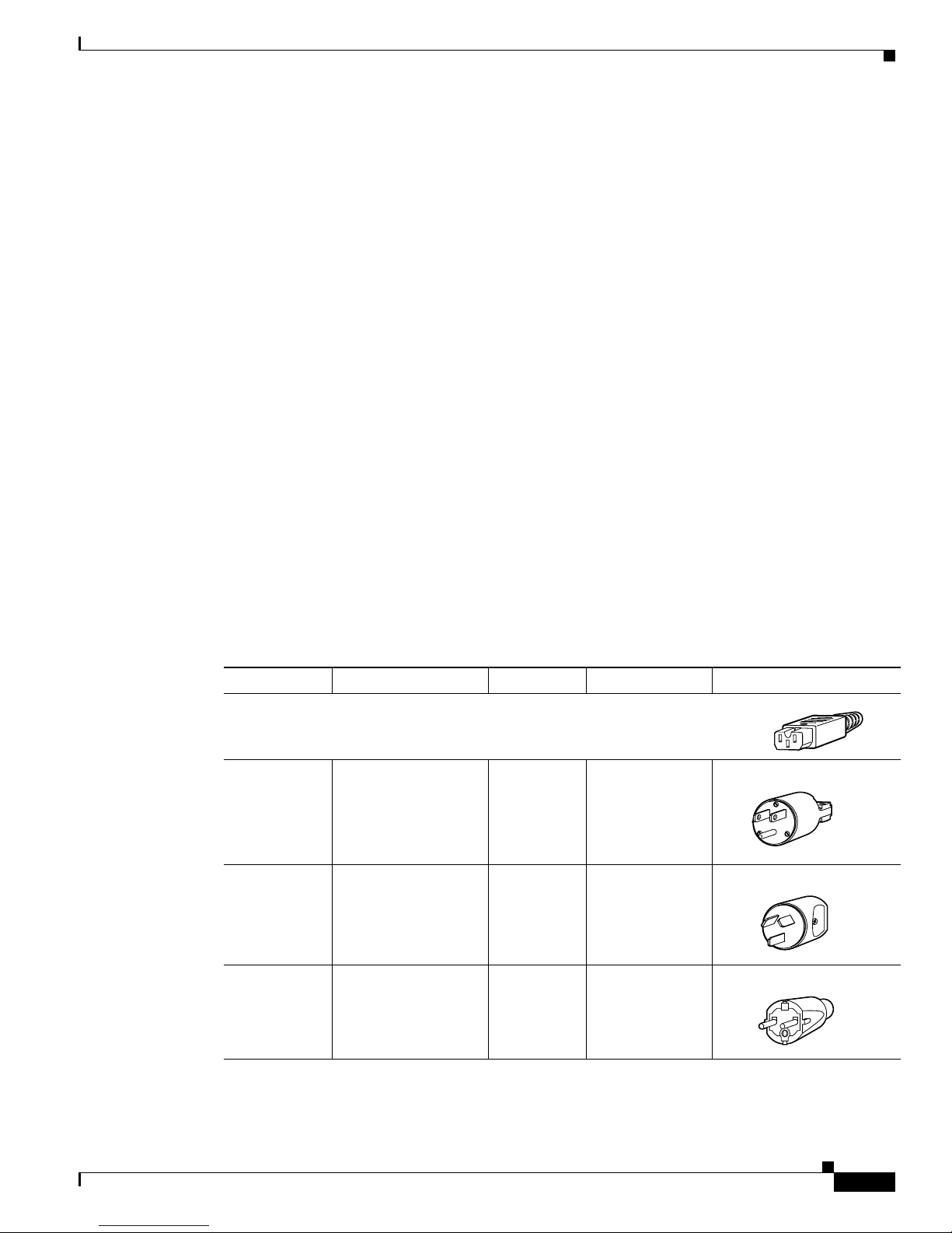
You will also need to provide power to the switch with the appropriate AC power cord for your location.
Table 2-1 lists the power cords that are used with the AC power supply.
Table 2-1 AC-Input Power Cord Options
Locale Part Number Length Plug Rating Plug Type
Appliance Coupler
300 W AC Power Supply
North America CAB-AC (72-0259) 8.2 ft (2.5 m) 125 VAC, 10 A
Australia, CAB-ACA
8.2 ft (2.5 m) 250 VAC, 10 A
(72-0746-01)
Europe (except
Italy)
78-17989-01
CAB-ACE (72-0460) 8.2 ft (2.5 m) 250 VAC, 10 A
Cisco ASA 5500 Series Hardware Installation Guide
2-5
Page 22

General Site Requirements
120358
120359
120356
251247
251248
Table 2-1 AC-Input Power Cord Options (continued)
Chapter 2 Preparing for Installation
Locale Part Number Length Plug Rating Plug Type
Italy CAB-ACI 72-0556 8.2 ft (2.5 m) 250 VAC, 10 A
Singapore
CAB-ACU 72-0557 8.2 ft (2.5 m) 250 VAC, 10 A
United
Kingdom
Argentina CAB-ACR
(37-0995-01)
Switzerland CAB-ACS
(72-1483-01)
Japan CAB-JPN
(72-1925-01)
8.2 ft (2.5 m) 250 VAC, 10 A
8.2 ft (2.5 m) 250 VAC, 10 A
8.2 ft (2.5 m) 250 VAC, 10 A
India CAB-IND-10A
(37-0863-01)
South Africa AIR-PWR-CORD-SA
(37-0346-01)
Configuring Equipment Racks
For information on physical specifications, see table 7 at the following url:
Cisco ASA 5500 Series Hardware Installation Guide
2-6
8.2 ft (2.5 m) 250 VAC, 10 A
8.2 ft (2.5 m) 250 VAC, 10 A
78-17989-01
Page 23

Chapter 2 Preparing for Installation
http://www.cisco.com/en/US/prod/collateral/vpndevc/ps6032/ps6094/ps6120/product_data_sheet0900a
ecd802930c5.html.
The following tips help you plan an acceptable equipment rack configuration:
• Enclosed racks must have adequate ventilation. Ensure that the rack is not overly congested, because
each chassis generates heat. An enclosed rack should have louvered sides and a fan to provide
cooling air.
• When mounting a chassis in an open rack, ensure that the rack frame does not block the intake or
exhaust ports. If the chassis is installed on slides, check the position of the chassis when it is seated
all the way into the rack.
• In an enclosed rack with a ventilation fan in the top, excessive heat generated by equipment near the
bottom of the rack can be drawn upward and into the intake ports of the equipment above it in the
rack. Ensure that you provide adequate ventilation for equipment at the bottom of the rack.
• Baffles can help to isolate exhaust air from intake air, which also helps to draw cooling air through
the chassis. The best placement of the baffles depends on the airflow patterns in the rack.
Experiment with different arrangements to position the baffles effectively.
General Site Requirements
78-17989-01
Cisco ASA 5500 Series Hardware Installation Guide
2-7
Page 24

General Site Requirements
Chapter 2 Preparing for Installation
Cisco ASA 5500 Series Hardware Installation Guide
2-8
78-17989-01
Page 25

CHA PTER
Installing the Adaptive Security Appliance
Installing the Adaptive Security Appliance
This section describes how to rack-mount and install the adaptive security appliance. You can mount the
adaptive security appliance in a 19-inch rack (with a 17.5- or 17.75-inch opening).
Warning
To prevent bodily injury when mounting or servicing this unit in a rack, you must take special
precautions to ensure that the system remains stable. The following guidelines are provided to ensure
your safety:
mounting this unit in a partially filled rack, load the rack from the bottom to the top with the heaviest component
at the bottom of the rack.If the rack is provided with stabilizing devices, install the stabilizers before mounting
or servicing the unit in the rack.
The following information can help plan equipment rack installation:
• Allow clearance around the rack for maintenance.
This unit should be mounted at the bottom of the rack if it is the only unit in the rack.When
Statement 1006
3
• If the rack contains stabilizing devices, install the stabilizers prior to mounting or servicing the unit
in the rack.
• When mounting a de vice in an enclosed rack, ensure adequate ventilation. Do not overcrowd an
enclosed rack.
• When m oun tin g a dev i ce i n an o pe n r ack, m ake sur e t ha t the r ack fr am e does not bl ock t h e i ntak e
or exhaust ports.
• If the rack contains only one unit, mount the unit at the bottom of the rack.
• If the rack is partially filled, load the rack from the bottom to the top, with the heaviest component
at the bottom of the rack.
This section contains the following topics:
• Rack-Mounting the Chassis, page 3-2
• Setting the Chassis on a Desktop, page 3-3
• Connecting the Interface Cables, page 3-4
Make sure that the rack is not congested, because each unit generates heat.
78-17989-01
Cisco ASA 5500 Series Hardware Installation Guide
3-1
Page 26

Installing the Adaptive Security Appliance
191311
Rack-Mounting the Chassis
Use the mounting brackets to mount the chassis to the front or the back of the rack, with the front panel
or the rear panel of the chassis facing outward. The part number for ordering a rack-mount kit for the
Cisco ASA 5510, Cisco ASA 5520, Cisco ASA 5540, and Cisco ASA 5550 is ASA5500-HW=. To
rack-mount the chassis, perform the following steps:
Step 1 Attach the rack-mount brackets to the chassis using the supplied screws. Attach the brackets to the holes
as shown in Figure 3-1. After the brackets are secured to the chassis, you can rack-mount it.
Note Figure 3-1 shows the rack mounting brackets attached to the rear of the chassis while Figure 3-2
shows the rack mounting brackets attached to the front of the chassis. You can attach the
mounting brackets to the front or the rear of the chassis so that you can have the front panel or
the rear panel of the chassis facing outward. Figure 3-1 shows the brackets attached to the rear
so you can see how that configuration appears while Figure 3-2 shows the brackets attached to
the front so that you can see how that configuration appears. In Step 1 and Step 2, you will
choose to have either the brackets rear mounted or front mounted but not both.
Chapter 3 Installing the Adaptive Security Appliance
Figure 3-1 Installing the Right and Left Brackets
Step 2 Attach the chassis to the rack using the supplied screws, as shown in Figure 3-2.
Cisco ASA 5500 Series Hardware Installation Guide
3-2
78-17989-01
Page 27

Chapter 3 Installing the Adaptive Security Appliance
119633
P
O
W
E
R
S
T
A
T
U
S
F
L
A
S
H
A
C
T
I
V
E
V
P
N
C
IS
C
O
A
S
A
5
5
4
0
SERIES
A
d
a
p
t
i
v
e
S
e
c
u
r
i
t
y
A
p
p
l
i
a
n
c
e
126919
2
1
Installing the Adaptive Security Appliance
.
To remove the chassis from the rack, remove the screws that attach the chassis to the rack, and then
remove the chassis.
Figure 3-2 Rack-Mounting the Chassis
Setting the Chassis on a Desktop
To set the chassis on a desktop, perform the following steps:
Step 1 Locate the rubber feet on the black adhesive strip that shipped with the chassis.
Figure 3-3 Identifying the Rubber Feet
1 Rubber feet 2 Black adhesive strip
Step 2 Place the chassis upside down, on a smooth, flat surface.
Step 3 Peel off the rubber feet from the black adhesive strip and press them adhesive-side down onto the bottom four
corners of the chassis, see Figure 3-4.
78-17989-01
Cisco ASA 5500 Series Hardware Installation Guide
3-3
Page 28

Installing the Adaptive Security Appliance
132185
1
Figure 3-4 Attaching the Rubber Feet
Chapter 3 Installing the Adaptive Security Appliance
1 Rubber feet
Step 4 Place the chassis right-side up on a flat, smooth, secure surface.
Step 5 Connect the interface cables. See the “Connecting the Interface Cables” section on page 3-4 for more
information.
Connecting the Interface Cables
This section describes how to connect the cables to the Console, Management, 4GE SSM, and SSM por ts.
In this document, SSM refers to an intelligent SSM, the AIP SSM or CSC SSM.
Note You can use any unused Ethernet interface on the device as the failover link. The failover link interface
is not configured as a normal networking interface; it should only be used for the failover link. You can
connect the LAN-based failover link by using a dedicated switch with no hosts or routers on the link or
by using a crossover Ethernet cable to link the units directly. For more information, see the Cisco Security
Appliance Command Line Configuration Guide.
Warning
Only trained and qualified personnel should install, replace, or service this equipment. Statement 49
Caution Read the safety warnings in the Regulatory Compliance and Safety Information for the Cisco ASA 5505
Adaptive Security Appliance and follow proper safety procedures when performing these steps.
Cisco ASA 5500 Series Hardware Installation Guide
3-4
78-17989-01
Page 29

Chapter 3 Installing the Adaptive Security Appliance
USB2
USB1
LNK SPD
3
LNK SPD2LNK SPD1LNK SPD
0
MGMT
92684
2
1
Note The RJ-45 Auxiliary port (labeled AUX on the chassis) is reserved for internal use at Cisco. The port is
not functional in shipping versions of the chassis; therefore, customers cannot connect to this port to run
the adaptive security appliance CLI.
To connect cables to the ports perform the following steps:
Step 1 Place the chassis on a flat, stable surface, or in a rack (if you are rack-mounting it.)
Step 2 Before connecting a computer or terminal to the ports, check to determine the baud rate of the serial port. The
baud rate must match the default baud rate (9600 baud) of the Console port of the adaptive security
appliance. Set up the terminal as follows: 9600 baud (default), 8 data bits, no parity, 1 stop bits, and Flow
Control (FC) = Hardware.
Step 3 Connect the cables to the ports.
a. Management port
The adaptive security appliance has a dedicated management interface referred to as the Management0/0
port. The Management0/0 port is a Fast Ethernet interface with a dedicated port used only for traffic
management.
Installing the Adaptive Security Appliance
Note You can configure any interface to be a management-only interface using the management-only
command. You can also disable management-only mode on the management interface. For more
information about this command, see the management-only command in the Cisco Security
Appliance Command Reference.
–
Connect one RJ-45 connector to the Management0/0 port, as shown in Figure 3-5.
–
Connect the other end of the Ethernet cable to the management port on your computer or
network device.
Figure 3-5 Connecting to the Management Port
1 Management port 2 RJ-45 to RJ-45 Ethernet cable
78-17989-01
Cisco ASA 5500 Series Hardware Installation Guide
3-5
Page 30

Installing the Adaptive Security Appliance
126982
FLASH
CONSOLE
AUX
POWER
STATUS
FLASH
VPN
ACTIVE
2
1
b. Console port
–
Connect the serial console cable as shown in Figure 3-6. The console cable has a DB-9
connector on one end for the serial port on your computer, and the other end is an RJ-45
connector.
–
Connect the RJ-45 connector to the Console port on the adaptive security appliance.
–
Connect the other end of the cable, the DB-9 connector, to the console port on your computer.
Figure 3-6 Connecting to the Console Cable
Chapter 3 Installing the Adaptive Security Appliance
1 RJ-45 Console port 2 RJ-45 to DB-9 console cable
Cisco ASA 5500 Series Hardware Installation Guide
3-6
78-17989-01
Page 31

Chapter 3 Installing the Adaptive Security Appliance
143147
USB1
MGMT
USB2
MGMT
USB2
C
isco SS
M
-4G
E
L
N
K
S
PD
0
123
POWER
S
T
A
T
U
S
USB1
1
2
c. 4GE SSM
• Ethernet port
–
Connect one RJ-45 connector to the Ethernet port of the 4GE SSM.
–
Connect the other end of the Ethernet cable to your network device, such as a router, switch or
hub.
Note The 4GE SSM is optional, this connection is necessary only if you have installed the 4GE SSM
on the adaptive security appliance.
Figure 3-7 Connecting to the RJ-45 port
Installing the Adaptive Security Appliance
1 Ethernet ports 2 RJ-45 connector
Note When using the 4GE SSM you can use the same numbered copper ports (RJ-45) and the SFP ports at the
same time. Use the media-type command in interface configuration mode to set the media type to copper
or fiber Gigabit Ethernet. For a complete description of the command syntax, see the Cisco ASA 5500
Series Command Reference.
• SFP modules
–
Insert and slide the SFP module into the SFP port until you hear a click. The click indicates that
the SFP module is locked into the port.
–
Remove the optical port plugs from the installed SFP as shown in Figure 3-8.
78-17989-01
Cisco ASA 5500 Series Hardware Installation Guide
3-7
Page 32

Installing the Adaptive Security Appliance
143146
1
STATUS
2
USB1
MGMT
USB2
MGMT
USB2
USB1
C
isco S
S
M
-4G
E
LN
K
SP
D
0
123
POWER
S
T
A
T
U
S
1
143148
2
Figure 3-8 Removing the Optical Port Plug
1 Optical port plug 2 SFP module
–
Connect the LC connector to the SFP module as shown in Figure 3-9.
Figure 3-9 Connecting the LC Connector
Chapter 3 Installing the Adaptive Security Appliance
1 LC connector 2 SFP module
–
Connect the other end to your network devices, such as routers, switches, or hubs.
Cisco ASA 5500 Series Hardware Installation Guide
3-8
78-17989-01
Page 33

Chapter 3 Installing the Adaptive Security Appliance
143149
USB1
MGMT
USB2
MGMT
USB2
POWER
STATUS
USB1
2
LINK?ACT
SPEED
1
d. SSM
–
Connect one RJ-45 connector to the management port on the SSM, as shown in Figure 3-10.
–
Connect the other end of the RJ-45 cable to your network devices.
Note SSMs are optional, this connection is necessary only if you have installed an SSM on the
adaptive security appliance.
Figure 3-10 Connecting to the Management Port
Installing the Adaptive Security Appliance
1 SSM management port 2 RJ-45 to RJ-45 cable
78-17989-01
Cisco ASA 5500 Series Hardware Installation Guide
3-9
Page 34

Installing the Adaptive Security Appliance
USB2
USB1
LNK SPD
3
LNK SPD2LNK SPD1LNK SPD
0
MGMT
92685
2
1
e. Ethernet ports
–
Connect the RJ-45 connector to the Ethernet port.
–
Connect the other end of the Ethernet cable to your network device, such as a router, switch or
hub.
Figure 3-11 Connecting Cables to Network Interfaces
Chapter 3 Installing the Adaptive Security Appliance
1 RJ-45 Ethernet ports 2 RJ-45 connector
Step 4 Connect the power cord to the adaptive security appliance and plug the other end to the power source.
For information on powering on a DC model, see the “Installing the DC Model” section on page 4-7.
Step 5 Power on the chassis.
Cisco ASA 5500 Series Hardware Installation Guide
3-10
78-17989-01
Page 35

CHA PTER
4
Maintenance and Upgrade Procedures
This chapter describes how to, remove and replace the chassis cover, the power supply, and the
CompactFlash. This chapter includes the following sections:
• Removing and Replacing the Chassis Cover, page 4-1
• Working in an ESD Environment, page 4-3
• Removing and Replacing a Lithium Battery in the SSM, page 4-4
• Removing and Replacing the Power Supply, page 4-4
• Installing the DC Model, page 4-7
• Removing and Replacing the CompactFlash, page 4-10
• Installing and Replacing the 4GE SSM, page 4-14
• Installing and Replacing the Intelligent SSM, page 4-20
• Upgrading Memory in the Adaptive Security Appliance, page 4-23
Removing and Replacing the Chassis Cover
This section describes how to remove and replace the chassis cover. This section includes the following
topics:
• Removing the Chassis Cover, page 4-1
• Replacing the Chassis Cover, page 4-2s
Removing the Chassis Cover
To remove the chassis cover, perform the following steps:
Note Removing the chassis cover does not affect Cisco warranty. Upgrading the adaptive security appliance
does not require any special tools and does not create any radio frequency leaks.
Step 1 Read the Regulatory Compliance and Safety Information for the Cisco ASA 5500 Series document.
Step 2 Power off the adaptive security appliance. Once the upgrade is complete, you can safely power on the
chassis.
Cisco ASA 5500 Series Hardware Installation Guide
78-17989-01
4-1
Page 36

Removing and Replacing the Chassis Cover
119635
POWER STATUS
FLASH
ACTIVE
VPN
CISCO ASA 5540
SERIES
Adaptive Security Appliance
119636
POWER STATUS
FLASH
ACTIVE
VPN
CISCO ASA 5540
SERIES
Adaptive Security Appliance
Chapter 4 Maintenance and Upgrade Procedures
Warning
Before working on a system that has an On/Off switch, turn OFF the power and unplug the power cord.
Statement 1
Step 3 Remove the screws from the top of the chassis (Figure 4-1).
Figure 4-1 Removing the Top Panel Screws
Step 4 Pull the top panel up as shown in Figure 4-2. Put the panel in a safe place.
Figure 4-2 Removing the Chassis Cover
Replacing the Chassis Cover
Caution Do not operate the adaptive security appliance without the chassis cover installed. The chassis cover
protects the internal components, prevents electrical shorts, and provides proper air-flow for cooling the
electronic components.
To replace the chassis cover, perform the following steps:
Step 1 Place the chassis on a secure surface with the front panel facing you.
Cisco ASA 5500 Series Hardware Installation Guide
4-2
78-17989-01
Page 37

Chapter 4 Maintenance and Upgrade Procedures
119637
POWER STATUS
FLASH
ACTIVE
VPN
CISCO ASA 5540
SERIES
Adaptive Security Appliance
119635
POWER STATUS
FLASH
ACTIVE
VPN
CISCO ASA 5540
SERIES
Adaptive Security Appliance
Step 2 Hold the top panel so the tabs at the rear of the top panel are aligned with the chassis bottom.
Step 3 Lower the front of the top panel onto the chassis as shown in Figure 4-3.
Figure 4-3 Replacing the Chassis Cover
Step 4 Fasten the top panel with the screws you set aside earlier as shown in Figure 4-4.
Working in an ESD Environment
Figure 4-4 Replacing the Screws
Step 5 Reinstall the chassis on a rack.
Step 6 Reinstall the network interface cables.
Working in an ESD Environment
Electrostatic discharge (ESD) can damage equipment and impair electrical circuitry. ESD damage occurs
when electronic components are improperly handled and can result in complete or intermittent failures.
Always follow ESD-prevention procedures when you remove and replace components. Ensure that the
chassis is electrically connected to earth ground. Wear an ESD-preventive wrist strap, ensuring that it
makes good skin contact. Connect the grounding clip to an unpainted surface of the chassis frame to
safely ground unwanted ESD voltages. To guard against ESD damage and shocks, the wrist strap and
cord must operate properly. If no wrist strap is available, ground yourself by touching the metal part of
the chassis.
78-17989-01
Cisco ASA 5500 Series Hardware Installation Guide
4-3
Page 38

Chapter 4 Maintenance and Upgrade Procedures
Removing and Replacing a Lithium Battery in the SSM
Removing and Replacing a Lithium Battery in the SSM
To remove and replace the battery in the SSM, perform the following steps:
Step 1 Remove the two screws at the left rear end of the chassis, and remove the slot cover as described in
“Installing and Replacing the Intelligent SSM” section on page 4-20.
Step 2 Slide the metal clip back and pull the battery out.
Step 3 Place the used battery aside.
Step 4 Replace the battery with a compactible Lithium CR-2032 battery (which is available at your local electronics
or drug store), by sliding the metal clip back and sliding the battery into place.
Step 5 Replace the chassis cover as described in the “Installing and Replacing the Intelligent SSM” section on
page 4-20.
Removing and Replacing the Power Supply
For information on power supply considerations including environmental operating ranges and power
requirements, see table 7 at the following url:
http://www.cisco.com/en/US/prod/collateral/vpndevc/ps6032/ps6094/ps6120/product_data_sheet0900a
ecd802930c5.html
For information on AC-input power cord options, see Ta b le 2-1 in the “Power Supply Considerations”
section on page 2-4
This section describes how to remove and replace the power supply, and includes the following topics:
• Removing the AC Power Supply, page 4-4
• Replacing the AC Power Supply, page 4-6
Removing the AC Power Supply
To remove the AC power supply, perform the following steps:
Step 1 Power off the adaptive security appliance.
Step 2 Remove the power cord and all other cables from the chassis.
Step 3 Remove the chassis from the rack if it is rack-mounted.
Step 4 Remove the chassis cover. See the “Installing and Replacing the Intelligent SSM” section on page 4-20
for more information.
Step 5 Place the chassis in an ESD-controlled environment. See the “Working in an ESD Environment” section
on page 4-3 for more information.
Cisco ASA 5500 Series Hardware Installation Guide
4-4
78-17989-01
Page 39

Chapter 4 Maintenance and Upgrade Procedures
119581
POWER
FLASH
STATUS
FLASH
ACTIVE
VPN
1
119639
1
2
Step 6 Lift the rear of the chassis from the surface and unscrew both the screws that secures the power supply to
the chassis, as shown in Figure 4-5.
Figure 4-5 Removing the Power Supply Screws
Removing and Replacing the Power Supply
1 Chassis bottom
Step 7 Locate the power connector on the system board.
Step 8 Unlatch the plug, then grasp the sides of the power connector and pull upward while rocking the connector
from side to side. Disconnect the power connector from the system board as shown in Figure 4-6.
Figure 4-6 Disconnecting the Power Connector
78-17989-01
1 AC power supply 2 Power connector
Cisco ASA 5500 Series Hardware Installation Guide
4-5
Page 40

Removing and Replacing the Power Supply
119578
3
1
2
4
Step 9 Remove the power supply brace by pulling it up and then out as shown in Figure 4-7.
Figure 4-7 Removing the Power Supply
Chapter 4 Maintenance and Upgrade Procedures
1 Back panel 3 Power supply brace
2 Power supply 4 Front panel
Step 10 From the back of the chassis, push the power supply forward, and then lift it up and out.
Replacing the AC Power Supply
To replace the AC power supply, perform the following steps:
Step 1 Insert the new power supply into place and slide it towards the back of the adaptive adaptive security
appliance.
Step 2 Lift the rear of the adaptive adaptive security appliance from the surface and reinstall both screws.
Cisco ASA 5500 Series Hardware Installation Guide
4-6
78-17989-01
Page 41

Chapter 4 Maintenance and Upgrade Procedures
119579
3
1
2
4
Step 3 Insert the power supply brace and press down until it fits into place, as shown in Figure 4-8.
Figure 4-8 Replacing the Power Supply Brace and the AC Power Supply
Installing the DC Model
1 Back panel 3 Power supply brace
2 Power supply 4 Front panel
Step 4 Connect the power connector to the system board.
Step 5 Replace the adaptive adaptive security appliance cover. See “Replacing the Chassis Cover” for more
information.
Step 6 Reinstall the network interface cables.
Installing the DC Model
Warning
Note The DC return connection should remain isolated from the system frame and chassis (DC-I). This
Before performing any of the following procedures, ensure that power is removed from the DC circuit.
To ensure that all power is OFF, locate the circuit breaker on the panel board that services the DC
circuit, switch the circuit breaker to the OFF position, and tape the switch handle of the circuit
breaker in the OFF position.
equipment is suitable for connection to intra-building wiring only.
Statement 7
To install the DC power model, perform the following steps:
78-17989-01
Cisco ASA 5500 Series Hardware Installation Guide
4-7
Page 42

Installing the DC Model
119640
+ –
1
4
3
2
Step 1 Read the Regulatory Compliance and Safety Information for the Cisco ASA 5500 Series document.
Step 2 Terminate the DC input wiring on a DC source capable of supplying at least 15 amps. A 15-amp circuit
Step 3 Locate the DC-input terminal box, see Figure 4-9.
Chapter 4 Maintenance and Upgrade Procedures
breaker is required at the 48 VDC facility power source. An easily accessible disconnect device should
be incorporated into the facility wiring.
Figure 4-9 DC-Input Terminal Box
1 Negative 3 Ground
2 Positive 4 On/Off switch
Step 4 Power off the adaptive security appliance. Ensure that power is removed from the DC circuit. To ensure
that all power is OFF, locate the circuit breaker on the panel board that services the DC circuit, switch
the circuit breaker to the OFF position, and tape the switch handle of the circuit breaker in the OFF
position.
Step 5 Remove the DC power supply plastic shield.
Step 6 The adaptive security appliance is equipped with two grounding holes at the side of the chassis, which
you can use to connect a two-hole grounding lug to the adaptive security appliance. Use 8-32 screws to
connect a copper standard barrel grounding lug to the holes. The adaptive security appliance requires a
lug where the distance between the center of each hole is 0.56 inches. A lug is not supplied with the
adaptive security appliance.
Step 7 Strip the ends of the wires for insertion into the power connect lugs on the adaptive security appliance.
4-8
Cisco ASA 5500 Series Hardware Installation Guide
78-17989-01
Page 43

Chapter 4 Maintenance and Upgrade Procedures
119641
+ –
+ –
1
2
3
Step 8 Insert the ground wire into the connector for the earth ground and tighten the screw on the connector.
See Figure 4-10, and using the same method as for the ground wire, connect the negative wire and then
the positive wire.
Note The DC return connection to this system is to remain isolated from the system frame and chassis.
Installing the DC Model
Figure 4-10 DC-Input Power Supply Connections
78-17989-01
1 Negative 3 Ground
2 Positive
Step 9 After wiring the DC power supply, remove the tape from the circuit breaker switch handle and reinstate
power by moving the handle of the circuit breaker to the ON position.
Step 10 Install any remaining interface boards as described in “Installing the DC Model” section on page 4-7.
Step 11 Replace the DC power supply plastic shield.
Step 12 Power on the adaptive security appliance from the switch at the rear of the chassis.
Note If you need to power cycle the DC adaptive security appliance, wait at least 5 seconds between
powering off the adaptive security appliance and powering it back on.
Cisco ASA 5500 Series Hardware Installation Guide
4-9
Page 44

Chapter 4 Maintenance and Upgrade Procedures
119580
1
Removing and Replacing the CompactFlash
Removing and Replacing the CompactFlash
The adaptive security appliance has two types of CompactFlash: the system CompactFlash (internal) and
the user CompactFlash (external). This section includes the following topics:
• Removing and Installing the System CompactFlash, page 4-10
• Removing and Installing the User CompactFlash, page 4-12
Removing and Installing the System CompactFlash
To remove and install the system CompactFlash, perform the following steps:
Step 1 Power off the adaptive security appliance.
Step 2 Remove the power cord and other cables from the adaptive security appliance.
Step 3 Remove the adaptive security appliance from the rack if it is rack-mounted.
Step 4 Place the adaptive security appliance in an ESD-controlled environment.
Step 5 Remove the adaptive security appliance cover.
Step 6 Carefully slide the CompactFlash out of its connector as shown in Figure 4-11. The CompactFlash has
a lip on its lower edge, which you can use to grip the CompactFlash. Otherwise, use sliding pressure with
your thumb or finger to slide the CompactFlash out of its connector.
Figure 4-11 Removing the System CompactFlash
1 System CompactFlash
Cisco ASA 5500 Series Hardware Installation Guide
4-10
78-17989-01
Page 45

Chapter 4 Maintenance and Upgrade Procedures
114004
1
Step 7 To install the system CompactFlash, align the new system CompactFlash with the connector on the riser
card.
Step 8 Push the system CompactFlash inward until it is fully seated in the connector, see Figure 4-12.
Figure 4-12 Replacing the System CompactFlash
Removing and Replacing the CompactFlash
1 System CompactFlash
Step 9 Replace the adaptive security appliance cover.
Step 10 Reinstall the network interface cables.
78-17989-01
Cisco ASA 5500 Series Hardware Installation Guide
4-11
Page 46

Removing and Replacing the CompactFlash
FLASH
CONSOLE
AUX
POWER
STATUS
FLASH
VPN
ACTIVE
1
2
246194
Removing and Installing the User CompactFlash
To remove and install the user CompactFlash, perform the following steps:
Note There are two types of CompactFlash release buttons. The release buttons function differently. In this
document we refer to them as Type A and Type B.
Step 1 Locate the user CompactFlash in its slot in the rear panel of the chassis. See Figure 4-13.
Figure 4-13 User CompactFlash and Release Button Location—Type A and B
Chapter 4 Maintenance and Upgrade Procedures
1 User CompactFlash in the slot 2 Release button extended
Step 2 Press the release button, the release button in Type A will pop out towards you. See Figure 4-14.
In Type B pressing the release button once will eject the CompactFlash, the release button will be slightly
extended. See Figure 4-15. If this is the case, skip Step 3 and go to Step 4.
Figure 4-14 Release Button Fully Extended—Type A
1
CONSOLE
FLASH
POWER
STATUS
ACTIVE
VPN
FLASH
2
1 User CompactFlash in the slot 2 Release button fully extended
AUX
246195
4-12
Cisco ASA 5500 Series Hardware Installation Guide
78-17989-01
Page 47

Chapter 4 Maintenance and Upgrade Procedures
FLASH
CONSOLE
AUX
POWER
STATUS
FLASH
VPN
ACTIVE
1
2
246196
Figure 4-15 User CompactFlash and Release Button Slightly Extended—Type B
Removing and Replacing the CompactFlash
1
2
FLASH
POWER
STATUS
ACTIVE
VPN
FLASH
CONSOLE
AUX
246208
1 User CompactFlash 2 Release button slightly extended
Step 3 Press the release button again, the CompactFlash will eject and the release button will be extended. See
Figure 4-16.
Figure 4-16 User CompactFlash and Release Button Extended—Type A
1 User CompactFlash 2 Release button extended
Step 4 Carefully pull the user CompactFlash out of the slot.
Note When the User CompactFlash slot is empty, the release button on Type A, see Figure 4-16 will
be extended and in Type B, see Figure 4-15 the release button will be slightly extended.
Step 5 Place the removed user CompactFlash on an antistatic surface or in a static shielding bag.
Step 6 To install a new CompactFlash, hold the new CompactFlash with the label facing up, insert the connector
end of the user CompactFlash into the slot until the card is seated in the connector. The user
CompactFlash is keyed so it cannot be inserted the wrong way.
78-17989-01
The release button will remain extended when you insert the CompactFlash see Figure 4-13.
Cisco ASA 5500 Series Hardware Installation Guide
4-13
Page 48

Installing and Replacing the 4GE SSM
132983
4
1
6
5
7
8
LNK
SPD0123
2
3
Cisco SSM-4GE
Installing and Replacing the 4GE SSM
The 4GE SSM has four 10/100/1000 Mbps, copper, RJ-45 ports and four optional 1000 Mbps,
Small-Form-Factor Pluggable (SFP) fiber ports.
Note When using the 4GE SSM you can use the same numbered copper ports (RJ-45) and the SFP ports at the
same time. Use the media-type command in interface configuration mode to set the media type to copper
or fiber Gigabit Ethernet. For a complete description of the command syntax, see the Cisco ASA 5500
Series Command Reference.
This section describes how to install and replace the 4GE SSM in the adaptive security appliance, and
includes the following topics:
• Overview, page 4-14
• Installing the 4GE SSM, page 4-15
• Replacing the 4GE SSM, page 4-16
• Installing and Removing the SFP Modules, page 4-16
Chapter 4 Maintenance and Upgrade Procedures
Overview
Figure 4-17 lists the 4GE SSM ports and LEDs.
Figure 4-17 4GE SSM Ports and LEDs
1 RJ-45 ports 5 Status LED
2 RJ-45 Link LED 6 SFP ports
3 RJ-45 Speed LED 7 SFP Link LED
4 Power LED 8 SFP Speed LED
Note Figure 4-17 shows SFP modules installed in the ports slots. You must order and install the SFP modules
if you want to use this feature. For more information on SFP ports and modules, see the “Installing and
Removing the SFP Modules” section on page 4-16.
Table 4-1 describes the 4GE SSM LEDs.
4-14
Cisco ASA 5500 Series Hardware Installation Guide
78-17989-01
Page 49

Chapter 4 Maintenance and Upgrade Procedures
119642
L
I
N
K
S
P
D
3
L
IN
K
S
P
D
2
L
IN
K
S
P
D
1
L
I
N
K
S
P
D
0
MGMT
USB2
USB1
F
L
A
S
H
POWER
STATUS
FLASH
VPN
ACTIVE
132984
MGMT
USB2
USB1
P
O
W
E
R
STATUS
Cisco SSM-4GE
L
N
K
S
P
D
0
1
23
L
I
N
K
S
P
D
3
L
I
N
K
S
P
D
2
L
I
N
K
S
P
D
1
L
I
N
K
S
P
D
0
F
L
A
S
H
POW
ER
STATUS
FLASH
VPN
ACTIVE
MGMT
USB2
USB1
Table 4-1 4GE SSM LEDs
LED Color State Description
2, 7 LINK Green Solid
Installing and Replacing the 4GE SSM
There is an Ethernet link.
3, 8 SPEED Off
4 POWER Green On The system has power.
5 STATUS Green
Installing the 4GE SSM
To install a new 4GE SSM for the first time, perform the following steps:
Step 1 Power off the adaptive security appliance.
Step 2 Locate the grounding strap from the accessory kit and fasten it to your wrist so that it contacts your bare
skin. Attach the other end to the chassis.
Step 3 Remove the two screws (as shown in Figure 4-18) at the left rear end of the chassis, and remove the slot
cover.
Green
Amber
Green
Amber
Flashing
10 MB
100 MB
1000 MB (GigE)
Flashing
Solid
Solid
There is Ethernet activity.
There is no network activity.
There is network activity at 100 Mbps.
There is network activity at 1000 Mbps.
The system is booting.
The system booted correctly.
The system diagnostics failed.
Figure 4-18 Removing the Screws from the Slot Cover
Step 4 Insert the 4GE SSM through the slot opening as shown in Figure 4-19.
Figure 4-19 Inserting the 4GE SSM into the Slot
78-17989-01
Cisco ASA 5500 Series Hardware Installation Guide
4-15
Page 50

Installing and Replacing the 4GE SSM
Step 5 Attach the screws to secure the 4GE SSM to the chassis.
Step 6 Power on the adaptive security appliance.
Step 7 Check the LEDs. If the 4GE SSM is installed properly the STATUS LED flashes during boot up and is
solid when operational.
Step 8 Connect one end of the RJ-45 cable to the port and the other end of the cable to your network devices.
Replacing the 4GE SSM
To replace an existing 4GE SSM, perform the following steps:
Step 1 Power off the adaptive security appliance.
Step 2 Locate the grounding strap from the accessory kit and fasten it to your wrist, so that it contacts your bare
skin. Attach the other end to the chassis.
Step 3 Remove the two screws at the left rear end of the chassis.
Step 4 Remove the 4GE SSM. Place it in a static bag and set it aside.
Chapter 4 Maintenance and Upgrade Procedures
Step 5 Replace the existing card by inserting the new 4GE SSM through the slot opening.
Step 6 Attach the screws to secure the 4GE SSM to the chassis.
Step 7 Power on the adaptive security appliance.
Step 8 Check the LEDs. If the 4GE SSM is installed properly, the POWER LED is solid green and the STATUS
LED is flashing during boot up.
Step 9 Connect the RJ-45 cable to the port and the other end of the cable to your network devices.
Installing and Removing the SFP Modules
The SFP is a hot-swappable input/output device that plugs into the SFP ports. The following SFP module
types are supported:
• Long wavelength/long haul 1000BASE-LX/LH (GLC-LH-SM=)
• Short wavelength 1000BASE-SX (GLC-SX-MM=)
This section describes how to install and remove the SFP modules in the adaptive security appliance to
provide optical Gigabit Ethernet connectivity. It contains the following topics:
• SFP Module, page 4-16
• Installing the SFP Module, page 4-18
• Removing the SFP Module, page 4-19
SFP Module
The adaptive security appliance uses a field-replaceable SFP module to establish Gigabit connections.
Table 4-2 lists the SFP modules that are suppo rted by the adaptive security appliance.
Cisco ASA 5500 Series Hardware Installation Guide
4-16
78-17989-01
Page 51

Chapter 4 Maintenance and Upgrade Procedures
Table 4-2 Supported SFP Modules
SFP Module Type of Connection Cisco Part Number
1000BASE-LX/LH Fiber-optic GLC-LH-SM=
1000BASE-SX Fiber-optic GLC-SX-MM=
The 1000BASE-LX/LH and 1000BASE-SX SFP modules are used to establish fiber-optic connections.
Use fiber-optic cables with LC connectors to connect to an SFP module. The SFP modules support 850
to 1550 nm nominal wavelengths. The cables must not exceed the required cable length for reliable
communications. Tab le 4 -3 lists the cable length requirements.
Table 4-3 Cabling Requirements for Fiber-Optic SFP Modules
Installing and Replacing the 4GE SSM
62.5/125 micron
SFP
Module
Multimode 850
nm
Fiber
LX/LH — — 550 m at
SX 275 m at
200 Mhz-km
50/125 micron
Multimode 850
nm Fiber
550 m at
500 Mhz-km
62.5/125 micron
Multimode 1310
nm Fiber
500 Mhz-km
50/125 micron
Multimode 1310
nm Fiber
550 m at
400 Mhz-km
9/125 micron
Single-mode
1310 nm Fiber
10 km
———
Use only Cisco certified SFP modules on the adaptive security appliance. Each SFP module has an
internal serial EEPROM that is encoded with security information. This encoding provides a way for
Cisco to identify and validate that the SFP module meets the requirements for the adaptive security
appliance.
Note Only SFP modules certified by Cisco are supported on the adaptive security appliance.
Caution Protect your SFP modules by inserting clean dust plugs into the SFPs after the cables are extracted from
them. Be sure to clean the optic surfaces of the fiber cables before you plug them back into the optical
bores of another SFP module. Avoid getting dust and other contaminants into the optical bores of your
SFP modules. The optics do not work correctly when obstructed with dust.
Warning
78-17989-01
Because invisible laser radiation may be emitted from the aperture of the port when no cable is
connected, avoid exposure to laser radiation and do not stare into open apertures.
Statement 70
Cisco ASA 5500 Series Hardware Installation Guide
4-17
Page 52

Installing and Replacing the 4GE SSM
132985
1
3
2
Installing the SFP Module
To install the SFP module in the 4GE SSM, perform the following steps:
Step 1 Line up the SFP module with the port and slide the SFP module into the port slot until it locks into
position as shown in Figure 4-20.
Figure 4-20 Installing an SFP Module
Chapter 4 Maintenance and Upgrade Procedures
1 Optical port plug 2 SFP port slot
3 SFP module
Caution Do not remove the optical port plugs from the SFP until you are ready to connect cabling.
Step 2 Remove the Optical port plug; then connect the network cable to the SFP module.
Step 3 Connect the other end of the cable to your network.
Caution The latching mechanism used on many SFPs locks them into place when cables are connected. Do not
pull on the cabling in an attempt to remove the SFP.
Cisco ASA 5500 Series Hardware Installation Guide
4-18
78-17989-01
Page 53

Chapter 4 Maintenance and Upgrade Procedures
117722
1 2 3 4
A
B
Removing the SFP Module
The SFP modules have different types of latching devices used to detach the SFP module from a port.
The following are the different types of modules:
• Mylar Tab Module
• Actuator/Button SFP Module
• Bale-Clasp SFP Module
• Plastic Collar Module
To remove the SFP module, perform the following steps:
Step 1 Disconnect all cables from the SFP.
Installing and Replacing the 4GE SSM
Warning
Caution The latching mechanism used on many SFPs locks the SFP into place when cables are connected. Do not
Because invisible laser radiation may be emitted from the aperture of the port when no cable is
connected, avoid exposure to laser radiation and do not stare into open apertures.
Statement 70
pull on the cabling in an attempt to remove the SFP.
Step 2 Disconnect the SFP latch as shown in Figure 4-21.
Note SFP modules use various latch designs to secure the module in the SFP port. Latch designs are not
linked to SFP model or technology type. For information on the SFP technology type and model, see
the label on the side of the SFP.
Figure 4-21 Disconnecting SFP Latch Mechanisms
1 Mylar tab 2 Actuator/Button
3 Bale-clasp 4 Plastic collar
Step 3 Grasp the SFP on both sides and remove it from the port.
78-17989-01
Cisco ASA 5500 Series Hardware Installation Guide
4-19
Page 54

Chapter 4 Maintenance and Upgrade Procedures
Installing and Replacing the Intelligent SSM
Installing and Replacing the Intelligent SSM
The Cisco ASA 5510, Cisco ASA 5520, Cisco ASA 5540 support the AIP SSM and the CSC SSM, also
referred to as the intelligent SSM in this document.The AIP SSM runs advanced IPS software that
provides security inspection. There are three types of AIP SSM: the AIP SSM 10, AIP SSM 20 and the
AIP SSM 40. The AIP SSM 10 and the AIP SSM 20 look identical, but the AIP SSM 20 has a faster
processor and more memory than the AIP SSM 10. The AIP SSM 40 has a faster processor and more
memory than both the AIP SSM 10 and the AIP SSM 20. Only one module (the AIP SSM 10,
AIP SSM 20, or the AIP SSM 40) can populate the slot at a time.
Table 4-4 lists the memory specifications for the AIP SSM 10, AIP SSM 20, and the AIP SSM 40.
Table 4-4 AIP/CSC SSM Memory Specifications
SSM CPU DRAM
AIP SSM 10 2.0 GHz Celeron 1.0 GB
AIP SSM 20 2.4 GHz Pentium 4 2.0 GB
AIP SSM 40 2.0 GHz Xeon LV 4.0 GB
For more information on the AIP SSM 10/20/40, see the “Managing the AIP SSM” section in the Cisco
Security Appliance Command Line Configuration Guide.
The CSC SSM runs Content Security and Control software. The CSC SSM provides protection against
viruses, spyware, spam, and other unwanted traffic. There are two types of CSC SSM: the CSC SSM 10,
and the CSC SSM 20. For more information on the CSC SSM 10/20, see the “Managing the CSC SSM”
section in the Cisco Security Appliance Command Line Configuration Guide.
Table 4-5 shows the AIP/CSC SSMs supported by each platform:
Ta b l e 4 - 5
Platform SSM Models
Cisco ASA 5510 AIP SSM 10
Cisco ASA 5520 AIP SSM 10
Cisco ASA 5540 AIP SSM 10
SSM
Support
CSC SSM 10
CSC SSM 20
4GE SSM
AIP SSM 20
AIP SSM 40
CSC SSM 10
CSC SSM 20
4GE SSM
AIP SSM 20
Cisco ASA 5500 Series Hardware Installation Guide
4-20
AIP SSM 40
4GE SSM
78-17989-01
Page 55

Chapter 4 Maintenance and Upgrade Procedures
119644
PWR
STATUS
SPEED
LINK/ACT
1 2
3 4
This section describes how to install and replace the AIP/CSC SSM in the adaptive security appliance,
and includes the following topics:
• Overview, page 4-21
• Installing and Replacing the AIP/CSC SSM, page 4-22
Overview
Figure 4-22 lists the AIP/CSC SSM 10/20 LEDs.
Installing and Replacing the Intelligent SSM
Figure 4-22 AIP/CSC SSM
10/ 2 0
LEDs
Table 4-6 describes the AIP/CSC SSM 10/20 LEDs.
Table 4-6 AIP/CSC SSM
10/ 2 0
LEDs
LED Color State Description
1 PWR Green On The system has power.
2 STATUS Green Flashing
Solid
3 LINK/ACT Green Solid
Flashing
4 SPEED Off
Green
Amber
10 MB
100 MB
1000 MB (GigE)
The system is booting.
The system has passed power-up diagnostics.
There is an Ethernet link.
There is Ethernet activity.
Indicates a 10MB connection.
Indicates a 100MB connection.
Indicates a 1000MB connection.
Figure 4-23 lists the AIP/CSC SSM 40 LEDs.
Figure 4-23 AIP/CSC SSM 40 LEDs
LNK SPD
0
1 2 3 4
78-17989-01
CISCO ASA SSM-40
S
U
WER
AT
ST
PO
270536
Cisco ASA 5500 Series Hardware Installation Guide
4-21
Page 56

Installing and Replacing the Intelligent SSM
119642
L
I
N
K
S
P
D
3
L
I
N
K
S
P
D
2
L
I
N
K
S
P
D
1
L
I
N
K
S
P
D
0
MGMT
USB2
USB1
F
L
A
S
H
POW
ER
STATUS
FLASH
VPN
ACTIVE
Table 4-6 describes the AIP/CSC SSM 10/20 LEDs.
Chapter 4 Maintenance and Upgrade Procedures
Table 4-7 AIP/CSC SSM
40
LEDs
LED Color State Description
1 LNK Green Solid
Flashing
2 SPEED Off
Green
Amber
10 MB
100 MB
1000 MB (GigE)
3 STATUS Green Solid
Flashing
4 POWER Green On The system has power.
Installing and Replacing the AIP/CSC SSM
This section describes how to install and replace the AIP/CSC SSM in the adaptive security appliance.
The section includes the following topics:
• Installing the AIP/CSC SSM, page 4-22
There is an Ethernet link.
There is Ethernet activity.
Indicates a 10MB connection.
Indicates a 100MB connection.
Indicates a 1000MB connection.
The system is booting.
The system has passed power-up diagnostics.
• Replacing the AIP/CSC SSM, page 4-23
Installing the AIP/CSC SSM
To install a new AIP/CSC SSM for the first time, perform the following steps:
Step 1 Enter the hw-mod mod 1 shut command in privileged EXEC mode. Verify that the module is down by
making sure that the LEDs are all off.
Step 2 Locate the grounding strap from the accessory kit and fasten it to your wrist so that it contacts your bare
skin. Attach the other end to the chassis.
Step 3 Remove the two screws at the left rear end of the chassis, and remove the slot cover as shown in
Figure 4-24.
Figure 4-24 Removing the Screws from the Slot Cover
Cisco ASA 5500 Series Hardware Installation Guide
4-22
78-17989-01
Page 57

Chapter 4 Maintenance and Upgrade Procedures
119643
P
W
R
S
T
A
T
U
S
S
P
E
E
D
L
IN
K
/A
C
T
L
I
N
K
S
P
D
3
L
IN
K
S
P
D
2
L
IN
K
S
P
D
1
L
I
N
K
S
P
D
0
MGMT
USB2
USB1
POW
ER
STATUS
FLASH
VPN
ACTIVE
Step 4 Insert the AIP/CSC SSM in to the slot opening as shown in Figure 4-25.
Figure 4-25 Inserting the AIP/CSC SSM into the Slot
Step 5 Attach the screws to secure the AIP/CSC SSM to the chassis.
Step 6 Enter the hw-mod mod 1 reset command in privileged EXEC mode to reset the AIP/CSC
SSM.
Step 7 Check the LEDs. If the AIP/CSC SSM is installed properly, the POWER LED is solid green and the
STATUS LED flashes green.
Upgrading Memory in the Adaptive Security Appliance
Replacing the AIP/CSC SSM
To replace an existing AIP/CSC SSM, perform the following steps:
Step 1 Enter the hw-mod mod 1 shut command in privileged EXEC mode. Verify that the module is down by
making sure that the LEDs are all off.
Step 2 Locate the grounding strap from the accessory kit and fasten it to your wrist, so that it contacts your bare
skin. Attach the other end to the chassis.
Step 3 Remove the two screws at the left rear end of the chassis.
Step 4 Remove the AIP/CSC SSM. Place it in a static bag and set it aside.
Step 5 Replace the existing card by inserting the new AIP/CSC SSM through the slot opening.
Step 6 Attach the screws to secure the AIP/CSC SSM to the chassis.
Step 7 Enter the hw-mod mod 1 reset command in privileged EXEC mode to reset the AIP/CSC
SSM.
Step 8 Check the LEDs. If the AIP/CSC SSM is installed properly, the POWER LED is solid green and the
STATUS LED flashes green.
Upgrading Memory in the Adaptive Security Appliance
This section describes how to upgrade the memory in the adaptive security appliance. The section
includes the following topics:
• Overview, page 4-24
• Removing and Installing the DIMM, page 4-25
78-17989-01
Cisco ASA 5500 Series Hardware Installation Guide
4-23
Page 58

Upgrading Memory in the Adaptive Security Appliance
Overview
Cisco ASA 5510
The memory upgrade kit, ASA5510-MEM-512=, allows you to upgrade the memory in your
Cisco ASA 5510.
To determine how much memory your adaptive security appliance has, use the show version command,
the example below is for the Cisco ASA 5510 chassis:
hostname# show version
Cisco Adaptive Security Appliance Software Version 8.0(4)
Device Manager Version 6.1(5)
Compiled on Thu 07-Aug-08 20:53 by builders
System image file is "disk0:/asa804-k8.bin"
Config file at boot was "startup-config"
ciscoasa up 2 days 10 hours
failover cluster up 2 days 11 hours
Chapter 4 Maintenance and Upgrade Procedures
Cisco ASA 5520/40
Hardware: ASA5510, 256 MB RAM, CPU Pentium 4 Celeron 1600 MHz
BIOS Flash AT49LW080 @ 0xffe00000, 1024KB
Table 4-8 lists the memory for the Cisco ASA 5510.
Table 4-8 Memory Upgrade
Model Current Memory Upgrade to
Cisco ASA 5510 256 MB 512 MB
The memory upgrade kits, ASA5520-MEM-2GB=, and the ASA5540-MEM-2GB= allows you to
upgrade the Cisco ASA 5520 and your Cisco ASA 5540 respectively. To see how much memory your
adaptive security appliance has, use the show version command.
To determine how much memory your adaptive security appliance has, use the show version command,
the example below is for the Cisco ASA 5520 chassis:
hostname# show version
Cisco Adaptive Security Appliance Software Version 8.0(0)
Device Manager Version 6.0(0)
Compiled on Mon 16-April-07 03:29 by root
System image file is "disk0:/cdisk.bin"
Config file at boot was "disk0:/main_backup.cfg"
hostname up 2 days 10 hours
failover cluster up 2 days 11 hours
Hardware: ASA5520, 512 MB RAM, CPU Pentium 4 Celeron 2000 MHz
BIOS Flash M50FW016 @ 0xffe00000, 2048KB
Cisco ASA 5500 Series Hardware Installation Guide
4-24
78-17989-01
Page 59

Chapter 4 Maintenance and Upgrade Procedures
Table 4-8 lists the memory for the Cisco ASA 5520 and Cisco ASA 5540.
Table 9 Memory Upgrade
Model Current Memory Upgrade to
Cisco ASA 5520 512 MB 2 GB
Cisco ASA 5540 1 GB 2 GB
Removing and Installing the DIMM
This section describes how to remove and install the memory module on the adaptive security appliance.
This section includes the following topics:
• Removing the DIMM, page 4-25
• Installing the DIMM, page 4-28
Removing the DIMM
Upgrading Memory in the Adaptive Security Appliance
To remove the memory module, perform the following steps:
Step 1 Power off the adaptive security appliance.
Step 2 Remove the power cord and other cables from the adaptive security appliance.
Step 3 Remove the adaptive security appliance from the rack if it is rack-mounted.
Step 4 Place the adaptive security appliance in an ESD-controlled environment. See the “Working in an ESD
Environment” section on page 4-3 for more information.
Step 5 Remove the adaptive security appliance cover. See the “Removing and Replacing the Chassis Cover”
section on page 4-1 for the procedure.
Step 6 Determine the location of the memory sockets. See Figure 4-26 for the Cisco ASA 5510 and Figure 4-27
for the Cisco ASA 5520 or Cisco ASA 5540.
Note Some Cisco ASA 5510 have only a single memory socket, see Figure 4-26. while others have
four memory sockets. In both cases, remove the existing DIMM, and replace it with the new
one. For memory upgrade in the Cisco ASA 5510 with four memory sockets, use slot 1 - P13 and
note that only one slot must be populated at all times.
78-17989-01
Cisco ASA 5500 Series Hardware Installation Guide
4-25
Page 60

Upgrading Memory in the Adaptive Security Appliance
3
1
2
Figure 4-26 System Memory Location in the Cisco ASA 5510
Chapter 4 Maintenance and Upgrade Procedures
1 DIMM
2 Memory Controller Hub (MCH)
3 CompactFlash socket
Cisco ASA 5500 Series Hardware Installation Guide
4-26
78-17989-01
Page 61

Chapter 4 Maintenance and Upgrade Procedures
Figure 4-27 System Memory Location in the Cisco ASA 5520 and the Cisco ASA 5540
1
Upgrading Memory in the Adaptive Security Appliance
P14
P16
331884
1 DIMM
Note All ASA-5520s and ASA-5540s manufactured before August 2011 have 4 DIMM sockets.
ASA-5520s and ASA-5540s manufactured after this date have 2 DIMM sockets.
Step 7 Locate the wrist grounding strap and connect one end to the adaptive security appliance, and securely
attach the other end to your wrist so it contacts your bare skin. See, “Working in an ESD Environment”
section on page 4-3 for more information.
Note Handle the edges of the DIMM only; avoid touching the memory modules, pins, or traces (the
metal fingers along the connector edge of the DIMM), along the connector edge.
To prevent ESD damage, handle DIMMs as shown in Figure 4-28.
Figure 4-28 Handling a DIMM
78-17989-01
Cisco ASA 5500 Series Hardware Installation Guide
4-27
Page 62

Upgrading Memory in the Adaptive Security Appliance
1
1
2
Step 8 Pull the latches away from the DIMM at both ends and release the DIMM from the socket. See
Figure 4-29.
Step 9 When both ends of the DIMM are released from the socket, grasp the ends of the DIMM with your thumb
and forefinger and pull the DIMM completely out of the socket.
Step 10 Place the DIMM in an antistatic container to protect it from ESD damage.
Figure 4-29 Releasing the DIMM Latches
Chapter 4 Maintenance and Upgrade Procedures
Installing the DIMM
To install the memory module, perform the following steps:
Step 1 Make sure that both latches on the DIMM connector are open.
Step 2 Remove a new DIMM from the antistatic container.
The DIMM is designed in such a way that the connector will fit only one way.
Step 3 Hold the DIMM component side up, with the connector edge away from you. Line up the notch in the
connector traces with the notch in the socket on the board.
Step 4 Carefully insert the connector edge into the socket and firmly press the DIMM into the socket until both
latches rotate to the close position against the DIMM.
Note For memory upgrade in the Cisco ASA 5510 with four memory sockets, use slot 1 - P13 and note
that only one slot must be populated at all times.
Cisco ASA 5500 Series Hardware Installation Guide
4-28
78-17989-01
Page 63

Chapter 4 Maintenance and Upgrade Procedures
2 2
1
Figure 4-30 Inserting the DIMM
Caution When inserting DIMMs, use pressure, but not excessive pressure as this can cause damage to the socket.
Step 5 When you finish installing the DIMM, replace the adaptive security appliance cover. See the “Removing
and Replacing the Chassis Cover” section on page 4-1 for the procedure.
Upgrading Memory in the Adaptive Security Appliance
Step 6 Reinstall the network interface cables.
Verifying the Memory Upgrade
Cisco ASA 5510
You can verify that the memory upgrade has been completed successfully by entering the show version
command, the example below is for the Cisco ASA 5510 chassis:
hostname# show version
Cisco Adaptive Security Appliance Software Version 8.0(4)
Device Manager Version 6.1(5)
Compiled on Thu 07-Aug-08 20:53 by builders
System image file is "disk0:/asa804-k8.bin"
Config file at boot was "startup-config"
ciscoasa up 2 days 10 hours
failover cluster up 2 days 11 hours
Hardware: ASA5510, 1 GB RAM, CPU Pentium 4 Celeron 1600 MHz
BIOS Flash AT49LW080 @ 0xffe00000, 1024KB
Cisco ASA 5520/40
You can verify that the memory upgrade has been completed successfully by entering the show version
command, the example below is for the Cisco ASA 5520 chassis:
hostname# show version
Cisco Adaptive Security Appliance Software Version 8.0(0)
Device Manager Version 6.0(0)
78-17989-01
Compiled on Mon 16-April-07 03:29 by root
Cisco ASA 5500 Series Hardware Installation Guide
4-29
Page 64

Upgrading Memory in the Adaptive Security Appliance
System image file is "disk0:/cdisk.bin"
Config file at boot was "disk0:/main_backup.cfg"
hostname up 2 days 10 hours
failover cluster up 2 days 11 hours
Hardware: ASA5520, 2 GB RAM, CPU Pentium 4 Celeron 2000 MHz
BIOS Flash M50FW016 @ 0xffe00000, 2048KB
Chapter 4 Maintenance and Upgrade Procedures
Cisco ASA 5500 Series Hardware Installation Guide
4-30
78-17989-01
Page 65

H5318
231 45678Pin Label
1
2
3
4
5
6
7
8
RD+
RD-
TD+
NC
NC
TD-
NC
NC
Cable Pinouts
This appendix describes pinout information, and includes the following sections:
• 10/100/1000BaseT Ports, page 1-1
• Console Port (RJ-45), page 1-2
• Console RJ-45 to DB-9 Adapter, page 1-4
• MGMT 10/100 Fast Ethernet Port, page 1-4
• SFP Fiber Ports, page 1-5
10/100/1000BaseT Ports
The adaptive security appliance supports 10/100/1000BaseT ports. You must use at least a Category 5
cable for 100/1000baseT operations, but a Category 3 cable can be used for 10BaseT operations.
APPENDIX
1
The 10/100/1000BaseT ports use standard RJ-45 connectors and supports MDI and MDI-X connectors.
Ethernet ports normally use MDI connectors and Ethernet ports on a hub normally use an MDI-X connector.
Use an Ethernet straight-through cable to connect an MDI to an MDI-X port. Use a cross-over cable to
connect an MDI to an MDI port, or an MDI-X to an MDI-X port.
Figure 1-1 shows the 10BaseT and the 100BaseTX connector (RJ-45).
Figure 1-1 10/100 Port Pinouts
78-17989-01
Cisco ASA 5500 Series Hardware Installation Guide
1-1
Page 66

Console Port (RJ-45)
231 45678Pin Label
1
2
3
4
5
6
7
8
TP0+
TP0-
TP1+
TP2+
TP2-
TP1-
TP3+
TP3-
H2936
8 7 6 5 4 3 2 1
RJ-45 connector
Appendix 1 Cable Pinouts
Figure 1-2 shows the 10BaseT, 100BaseTX, and 1000BASE-T connector (RJ-45).
Figure 1-2 10/100/1000 Port Pinouts
Console Port (RJ-45)
Cisco products use the following types of RJ-45 cables:
• Straight-through
• Crossover
Note Cisco does not provide these cables; they are widely available from other sources.
Figure 1-3 shows the RJ 45 cable.
Figure 1-3 RJ-45 Cable
1-2
Cisco ASA 5500 Series Hardware Installation Guide
78-17989-01
Page 67

Appendix 1 Cable Pinouts
H5663
Console Port (RJ-45)
To identify the RJ-45 cable type, hold the two ends of the cable next to each other so that you can see
the colored wires inside the ends, as shown in Figure 1-4.
Figure 1-4 RJ-45 Cable Identification
Examine the sequence of colored wires to determine the type of RJ-45 cable, as follows:
• Straight-through—The colored wires are in the same sequence at both ends of the cable.
• Crossover—The first (far left) colored wire at one end of the cable is the third colored wire at the
other end of the cable.
Table 1-1 lists the rolled (console) cable pinouts for RJ-45.
Table 1-1 RJ-45 Rolled (Console) Cable Pinouts
Signal Pin Pin Pin
- 18-
- 27-
- 36-
- 45-
- 54-
- 63-
- 72-
- 81-
78-17989-01
Cisco ASA 5500 Series Hardware Installation Guide
1-3
Page 68

Console RJ-45 to DB-9 Adapter
Console RJ-45 to DB-9 Adapter
Table 1-2 lists the cable pinouts for RJ-45 to DB-9 or DB-25.
Table 1-2 Cable Pinouts for RJ-45 to DB-9 or DB-25
Signal RJ-45 Pin DB-9 Pin
RTS 8 8
DTR 7 6
TxD 6 2
GND 5 5
GND 4 5
RxD 3 3
DSR 2 4
CTS 1 7
Appendix 1 Cable Pinouts
MGMT 10/100 Fast Ethernet Port
The MGMT 10/100 Fast Ethernet port has an RJ-45 connector. You can use a modular, RJ-45,
straight-through UTP cable to connect the management port to an external hub, switch, or router.
Table 1-3 lists the cable pinouts for 10/100BASE-T Management Port Cable Pinouts (MDI).
Table 1-3 10/100BASE-T Management Port Cable Pinouts (MDI)
Signal Pin
TD+ 1
TD- 2
RD+ 3
RD- 6
Not used 4
Not used 5
Not used 7
Not used 8
Cisco ASA 5500 Series Hardware Installation Guide
1-4
78-17989-01
Page 69

Appendix 1 Cable Pinouts
SFP Fiber Ports
Table 1-4 lists the types of SFP modules and connectors used in the adaptive security appliance.
Table 1-4 Types of SFP Modules and Connectors
Port Compliance Connector Fiber Type
Gigabit Ethernet 1000BASE-SX SW MMF
Table 1-5 lists the SFP port cabling specifications for the SFP modules and connectors used in the
adaptive security appliance.
Table 1-5 SFP Port Cabling Specifications
SFP Fiber Ports
1000BASE-LX LW SMF
Cisco Product
Number
GLC-SX-MM= 850 62.5
GLC-LH-SM= 1300 9.0 1.0625 10 km
Wavelength
(nanometer)
Core Size
(micron) Baud Rate Cable Distance
50.0
1.0625
1.0625
300 m
500 m
78-17989-01
Cisco ASA 5500 Series Hardware Installation Guide
1-5
Page 70

SFP Fiber Ports
Appendix 1 Cable Pinouts
Cisco ASA 5500 Series Hardware Installation Guide
1-6
78-17989-01
Page 71

INDEX
Numerics
1000 W power supplies
power cords (table)
4GE SSM 4-15, 4-22
2-5
A
AC-input power cords
product numbers (table)
ASA
replacing lithium battery
AUX port 1-2
C
chassis covers
removing
replacing 4-2
circuit breaker for DC unit 2-3
Cisco warranty 2-2
CompactFlash
External
Internal 4-10, 4-12
Console port 3-6
CPU 1-5
4-1
1-2, 1-3
2-5
4-4
ESD
preventing
2-3, 4-3
F
failover 1-5, 3-4
fans
ventilation
2-7
G
grounding lug
attaching
4-8
I
interface cables 3-4
4GE SSM 3-7
console port 3-6
management port 3-5
SSM 3-9
L
LC connector 3-8
LEDs 1-4, 4-14, 4-21
E
electrostatic discharge
see ESD
equipment racks
2-7
tips
78-17989-01
M
memory requirements 1-5
MGMT 1-2, 1-3, 3-5
Cisco ASA 5500 Series Hardware Installation Guide
IN-1
Page 72

Index
N
Network interfaces 1-2
P
panel
removing
power LEDs 1-3, 1-4, 4-14, 4-21
power supplies
considerations
product overview 1-2
4-2
2-4
R
rear panels (figure) 1-4
RJ-45 connector
pinouts
RJ-45 port 3-7
rubber feet
attaching
1-4
3-3
W
warranty 2-2
S
safety 2-2
Serial Console port 1-2, 1-3
SFP 3-7, 4-16
site environment 2-4
SSM 3-9, 4-4
4GE SSM
connecting
installing 4-15, 4-22
LEDs 1-3, 4-14
replacing 4-16, 4-23
3-7
V
ventilation fans 2-7
Cisco ASA 5500 Series Hardware Installation Guide
IN-2
78-17989-01
 Loading...