

Page 1

Catalyst 3850 Switch Hardware Installation Guide
September 2013
Cisco Systems, Inc.
www.cisco.com
Cisco has more than 200 offices worldwide.
Addresses, phone numbers, and fax numbers
are listed on the Cisco website at
www.cisco.com/go/offices.
Text Part Number: OL-26779-02
Page 2

THE SPECIFICATIONS AND INFORMATION REGARDING THE PRODUCTS IN THIS MANUAL ARE SUBJECT TO CHANGE WITHOUT NOTICE. ALL
STATEMENTS, INFORMATION, AND RECOMMENDATIONS IN THIS MANUAL ARE BELIEVED TO BE ACCURATE BUT ARE PRESENTED WITHOUT
WARRANTY OF ANY KIND, EXPRESS OR IMPLIED. USERS MUST TAKE FULL RESPONSIBILITY FOR THEIR APPLICATION OF ANY PRODUCTS.
THE SOFTWARE LICENSE AND LIMITED WARRANTY FOR THE ACCOMPANYING PRODUCT ARE SET FORTH IN THE INFORMATION PACKET THAT
SHIPPED WITH THE PRODUCT AND ARE INCORPORATED HEREIN BY THIS REFERENCE. IF YOU ARE UNABLE TO LOCATE THE SOFTWARE LICENSE
OR LIMITED WARRANTY, CONTACT YOUR CISCO REPRESENTATIVE FOR A COPY.
The following information is for FCC compliance of Class A devices: This equipment has been tested and found to comply with the limits for a Class A digital device, pursuant
to part 15 of the FCC rules. These limits are designed to provide reasonable protection against harmful interference when the equipment is operated in a commercial
environment. This equipment generates, uses, and can radiate radio-frequency energy and, if not installed and used in accordance with the instruction manual, may cause
harmful interference to radio communications. Operation of this equipment in a residential area is likely to cause harmful interference, in which case users will be required
to correct the interference at their own expense.
The following information is for FCC compliance of Class B devices: The equipment described in this manual generates and may radiate radio-frequency energy. If it is not
installed in accordance with Cisco’s installation instructions, it may cause interference with radio and television reception. This equipment has been tested and found to
comply with the limits for a Class B digital device in accordance with the specifications in part 15 of the FCC rules. These specifications are designed to provide reasonable
protection against such interference in a residential installation. However, there is no guarantee that interference will not occur in a particular installation.
Modifying the equipment without Cisco’s written authorization may result in the equipment no longer complying with FCC requirements for Class A or Class B digital
devices. In that event, your right to use the equipment may be limited by FCC regulations, and you may be required to correct any interference to radio or television
communications at your own expense.
You can determine whether your equipment is causing interference by turning it off. If the interference stops, it was probably caused by the Cisco equipment or one of its
peripheral devices. If the equipment causes interference to radio or television reception, try to correct the interference by using one or more of the following measures:
• Turn the television or radio antenna until the interference stops.
• Move the equipment to one side or the other of the television or radio.
• Move the equipment farther away from the television or radio.
• Plug the equipment into an outlet that is on a different circuit from the television or radio. (That is, make certain the equipment and the television or radio are on circuits
controlled by different circuit breakers or fuses.)
Modifications to this product not authorized by Cisco Systems, Inc. could void the FCC approval and negate your authority to operate the product.
The Cisco implementation of TCP header compression is an adaptation of a program developed by the University of California, Berkeley (UCB) as part of UCB’s public
domain version of the UNIX operating system. All rights reserved. Copyright © 1981, Regents of the University of California.
NOTWITHSTANDING ANY OTHER WARRANTY HEREIN, ALL DOCUMENT FILES AND SOFTWARE OF THESE SUPPLIERS ARE PROVIDED “AS IS” WITH
ALL FAULTS. CISCO AND THE ABOVE-NAMED SUPPLIERS DISCLAIM ALL WARRANTIES, EXPRESSED OR IMPLIED, INCLUDING, WITHOUT
LIMITATION, THOSE OF MERCHANTABILITY, FITNESS FOR A PARTICULAR PURPOSE AND NONINFRINGEMENT OR ARISING FROM A COURSE OF
DEALING, USAGE, OR TRADE PRACTICE.
IN NO EVENT SHALL CISCO OR ITS SUPPLIERS BE LIABLE FOR ANY INDIRECT, SPECIAL, CONSEQUENTIAL, OR INCIDENTAL DAMAGES, INCLUDING,
WITHOUT LIMITATION, LOST PROFITS OR LOSS OR DAMAGE TO DATA ARISING OUT OF THE USE OR INABILITY TO USE THIS MANUAL, EVEN IF CISCO
OR ITS SUPPLIERS HAVE BEEN ADVISED OF THE POSSIBILITY OF SUCH DAMAGES.
Cisco and the Cisco logo are trademarks or registered trademarks of Cisco and/or its affiliates in the U.S. and other countries. To view a list of Cisco trademarks, go to this
URL: www.cisco.com/go/trademarks. Third-party trademarks mentioned are the property of their respective owners. The use of the word partner does not imply a partnership
relationship between Cisco and any other company. (1110R)
Catalyst 3850 Switch Hardware Installation Guide
© 2013 Cisco Systems, Inc. All rights reserved.
Page 3

CONTENTS
Preface ix
Purpose ix
Document Conventions ix
Related Documentation x
Obtaining Documentation and Submitting a Service Request x
CHAPTER
1 Product Overview 1-1
Switch Models 1-2
Front Panel 1-4
10/100/1000 Ethernet Ports 1-5
PoE, PoE+, and Cisco UPOE Ports 1-5
Management Ports 1-6
USB Mini-Type B Port 1-6
USB Type A Port 1-7
Network Modules 1-7
SFP and SFP+ Modules 1-8
LEDs 1-9
SYST LED 1-10
XPS LED 1-10
Port LEDs and Modes 1-11
USB Console LED 1-13
S-PWR LED 1-13
ACTV LED 1-14
STACK LED 1-14
PoE LED 1-15
Network Module LEDs 1-16
OL-26779-02
Rear Panel 1-17
RJ-45 Console Port LED 1-17
StackWise Ports 1-18
Power Supply Modules 1-18
Fan Modules 1-21
StackPower Connector 1-22
Management Ports 1-23
Ethernet Management Port 1-23
Catalyst 3850 Switch Hardware Installation Guide
iii
Page 4

Contents
RJ-45 Console Port 1-23
Management Options 1-23
Network Configurations 1-24
CHAPTER
2 Switch Installation 2-1
Preparing for Installation 2-1
Safety Warnings 2-1
Installation Guidelines 2-3
Tools and Equipment 2-4
Verifying Switch Operation 2-4
Powering Off the Switch 2-4
Planning a Switch Data Stack 2-4
Switch Stacking and Power Stacking Guidelines 2-5
Data Stack Cabling Configurations 2-5
Data Stack Bandwidth and Partitioning Examples 2-6
Power-On Sequence for Switch Data Stacks 2-7
Planning a StackPower Stack 2-8
StackPower Stacking Guidelines 2-8
StackPower Cabling Configurations 2-9
StackPower Partitioning Examples 2-11
Installing the Switch 2-11
Rack-Mounting 2-12
Attaching the Rack-Mount Brackets 2-13
Mounting the Switch in a Rack 2-15
Table- or Shelf-Mounting 2-16
After Installing the Switch 2-16
CHAPTER
iv
Connecting to the StackWise Ports 2-17
Connecting to the StackPower Ports 2-18
Installing a Network Module in the Switch 2-19
Installing and Removing SFP and SFP+ Modules 2-19
Connecting Devices to the Ethernet Ports 2-19
10/100/1000 Ethernet Port Connections 2-19
PoE+ and Cisco UPOE Port Connections 2-20
Where to Go Next 2-21
3 Installing a Network Module 3-1
Overview 3-1
Network Module LEDs 3-4
Catalyst 3850 Switch Hardware Installation Guide
OL-26779-02
Page 5

Installing a Network Module in the Switch 3-4
Safety Warnings 3-4
Tools and Equipment 3-5
Installing Network Modules 3-5
Configuring a Network Module 3-7
C3850-NM-4-1G module 3-7
C3850-NM-4-10G module 3-7
C3850-NM-2-10G module 3-8
Supported GBICs 3-8
Removing a Network Module 3-9
SFP and SFP+ Modules 3-9
Installing SFP and SFP+ Modules 3-9
Removing SFP or SFP+ Modules 3-11
Finding the Network Module Serial Number 3-11
Contents
CHAPTER
CHAPTER
4 Power Supply Installation 4-1
Power Supply Module Overview 4-1
Installation Guidelines 4-5
Installing or Replacing an AC Power Supply 4-6
Installing a DC Power Supply 4-7
Equipment That You Need 4-8
Grounding the Switch 4-8
Installing the DC Power Supply in the Switch 4-11
Wiring the DC Input Power Source 4-11
Finding the Power Supply Module Serial Number 4-12
5 Installing the Fan 5-1
Overview 5-1
Fan Module Installation 5-2
Installation Guidelines 5-2
Installing a Fan Module 5-2
Finding the Fan Module Serial Number 5-3
CHAPTER
OL-26779-02
6 Troubleshooting 6-1
Diagnosing Problems 6-1
Switch POST Results 6-1
Switch LEDs 6-1
Switch Connections 6-2
Catalyst 3850 Switch Hardware Installation Guide
v
Page 6

Contents
Bad or Damaged Cable 6-2
Ethernet and Fiber Cables 6-2
Link Status 6-2
10/100/1000 Port Connections 6-3
PoE and PoE+ Port Connections 6-3
SFP Modules 6-3
Interface Settings 6-4
Ping End Device 6-4
Spanning Tree Loops 6-4
Switch Performance 6-4
Speed, Duplex, and Autonegotiation 6-4
Autonegotiation and Network Interface Cards 6-5
Cabling Distance 6-5
Resetting the Switch 6-5
Finding the Switch Serial Number 6-6
APPENDIX
APPENDIX
Replacing a Failed Data Stack Member 6-6
A Technical Specifications A-1
Switch Specifications A-1
Power Supply Module Specifications A-2
Fan Module Specifications A-4
B Connector and Cable Specifications B-1
Connector Specifications B-1
10/100/1000 Ports B-1
10-Gigabit Ethernet CX1 (SFP+ Copper) Connectors B-2
SFP and SFP+ Modules B-2
10/100/1000 Ethernet Management Port B-3
Console Port B-4
Cable and Adapter Specifications B-5
StackWise Cables B-5
SFP and SFP+ Module Cable Specifications B-5
Four Twisted-Pair Cable Pinouts B-6
Two Twisted-Pair Cable Pinouts B-6
Identifying a Crossover Cable B-7
Console Port Adapter Pinouts B-7
vi
Catalyst 3850 Switch Hardware Installation Guide
OL-26779-02
Page 7

Contents
APPENDIX
C Configuring the Switch with the CLI-Based Setup Program C-1
Accessing the CLI C-1
Accessing the CLI Through Express Setup C-1
Accessing the CLI Through a Console Port C-2
RJ-45 Console Port C-2
USB Console Port C-2
Installing the Cisco Microsoft Windows USB Device Driver C-4
Uninstalling the Cisco Microsoft Windows USB Driver C-4
Uninstalling the Cisco Microsoft Windows XP and 2000 USB Driver C-4
Uninstalling the Cisco Microsoft Windows Vista and Windows 7 USB Driver C-5
Entering the Initial Configuration Information C-5
IP Settings C-5
Configuring the Setup Program C-5
OL-26779-02
Catalyst 3850 Switch Hardware Installation Guide
vii
Page 8

Contents
viii
Catalyst 3850 Switch Hardware Installation Guide
OL-26779-02
Page 9

Purpose
Preface
This guide describes the hardware features of the Catalyst 3850 switches. It describes the physical and
performance characteristics of each switch, explains how to install a switch, and provides
troubleshooting information.
This guide does not describe system messages that you might receive or how to configure your switch.
See the switch software configuration guide, the switch command reference, and the switch system
message guide on
http://www.cisco.com/go/cat3850_docs
Document Conventions
This document uses the following conventions.
Note Means reader take note. Notes contain helpful suggestions or references to materials not contained in
this manual.
Caution Means reader be careful. In this situation, you might do something that could result in equipment
damage or loss of data.
OL-26779-02
Catalyst 3850 Switch Hardware Installation Guide
ix
Page 10

Preface
Warning
IMPORTANT SAFETY INSTRUCTIONS
This warning symbol means danger. You are in a situation that could cause bodily injury. Before you
work on any equipment, be aware of the hazards involved with electrical circuitry and be familiar
with standard practices for preventing accidents. Use the statement number provided at the end of
each warning to locate its translation in the translated safety warnings that accompanied this
device.
SAVE THESE INSTRUCTIONS
The safety warnings for this product are translated into several languages in the Regulatory Compliance
and Safety Information for the Catalyst 3850 Switch that is available on Cisco.com. The EMC regulatory
statements are also included in that guide.
Statement 1071
Related Documentation
Note Before installing or upgrading the switch, refer to the switch release notes.
• Catalyst 3850 Switch documentation at:
http://www.cisco.com/go/cat3850_docs
• Cisco SFP and SFP+ modules documentation, including compatibility matrixes at:
http://www.cisco.com/en/US/products/hw/modules/ps5455/tsd_products_support_series_home.ht
ml
• Cisco Validated Designs documents at:
http://www.cisco.com/go/designzone
• Error Message Decoder, located at:
https://www.cisco.com/cgi-bin/Support/Errordecoder/index.cgi
Obtaining Documentation and Submitting a Service Request
For information on obtaining documentation, submitting a service request, and gathering additional
information, see the monthly What’s New in Cisco Product Documentation, which also lists all new and
revised Cisco technical documentation, at:
http://www.cisco.com/en/US/docs/general/whatsnew/whatsnew.html
Subscribe to the What’s New in Cisco Product Documentation as a Really Simple Syndication (RSS) feed
and set content to be delivered directly to your desktop using a reader application. The RSS feeds are a free
service and Cisco currently supports RSS Version 2.0.
Catalyst 3850 Switch Hardware Installation Guide
x
OL-26779-02
Page 11

CHAP T E R
1
Product Overview
The Catalyst 3850 series switches are Ethernet switches to which you can connect devices such as
Cisco IP Phones, Cisco Wireless Access Points, workstations, and other network devices such as servers,
routers, and other switches.
The Catalyst 3850 switches support stacking through Cisco StackWise-480 technology and power
management through StackPower. The StackWise technology for the Catalyst 3850 switches is called
StackWise-480.
Unless otherwise noted, the term switch refers to a standalone switch and to a switch stack.
• Switch Models, page 1-2
• Front Panel, page 1-4
• Rear Panel, page 1-17
• Management Options, page 1-23
OL-26779-02
Catalyst 3850 Switch Hardware Installation Guide
1-1
Page 12

Switch Models
Switch Models
Table 1-1 Catalyst 3850 Switch Models
Switch Model Cisco IOS Image Description
Catalyst 3850-24T-L LAN Base Stackable 24 10/100/1000 Ethernet ports,
Catalyst 3850-48T-L LAN Base Stackable 48 10/100/1000 Ethernet ports,
Catalyst 3850-24P-L LAN Base Stackable 24 10/100/1000 PoE+
Catalyst 3850-48P-L LAN Base Stackable 48 10/100/1000 PoE+ ports,
Catalyst 3850-48F-L LAN Base Stackable 48 10/100/1000 PoE+ ports,
Catalyst 3850-24U-L LAN Base Stackable 24 10/100/1000 Cisco Universal Power
Catalyst 3850-48U-L LAN Base Stackable 48 10/100/1000 Cisco UPOE ports,
Catalyst 3850-24T-S IP Base Stackable 24 10/100/1000 Ethernet ports,
Catalyst 3850-48T-S IP Base Stackable 48 10/100/1000 Ethernet ports,
Catalyst 3850-24P-S IP Base Stackable 24 10/100/1000 PoE+ ports,
Catalyst 3850-48P-S IP Base Stackable 48 10/100/1000 PoE+ ports,
Catalyst 3850-48F-S IP Base Stackable 48 10/100/1000 PoE+ ports,
Catalyst 3850-24U-S IP Base Stackable 24 10/100/1000 Cisco UPOE ports,
Catalyst 3850-48U-S IP Base Stackable 48 10/100/1000 Cisco UPOE ports,
Catalyst 3850-24T-E IP Services Stackable 24 10/100/1000 Ethernet ports,
Catalyst 3850-48T-E IP Services Stackable 48 10/100/1000 Ethernet ports,
Catalyst 3850-24P-E IP Services Stackable 24 10/100/1000 PoE+ ports,
Catalyst 3850-48P-E IP Services Stackable 48 10/100/1000 PoE+ ports,
Catalyst 3850-48F-E IP Services Stackable 48 10/100/1000 PoE+ ports,
Chapter 1 Product Overview
1 network module slot
1 network module
1 network module slot
1 network module
1 network module
Over Ethernet (Cisco UPOE) ports,
1 network module slot
1 network module slot
1 network module slot
1 network module
1 network module slot, 715-W power supply
1 network module
1 network module
1 network module slot, 1100-W power supply
1 network module slot
1 network module slot
1 network module
1 network module slot
1 network module
1 network module
1
, 350-W power supply
slot1, 350-W power supply
2
1
, 715-W power supply
1
slot, 715-W power supply
1
slot, 1100-W power supply
1
, 1100-W power supply
1
, 1100-W power supply
1
, 350-W power supply
slot1, 350-W power supply
1
slot, 715-W power supply
1
slot, 1100-W power supply
1
, 1100-W power supply
1
, 350-W power supply
slot1, 350-W power supply
1
, 715-W power supply
1
slot, 715-W power supply
1
slot, 1100-W power supply
ports,
1-2
Catalyst 3850 Switch Hardware Installation Guide
OL-26779-02
Page 13

Chapter 1 Product Overview
Table 1-1 Catalyst 3850 Switch Models (continued)
Switch Model Cisco IOS Image Description
Catalyst 3850-24PW-S IP Base Catalyst 3850 24-port PoE IP Base with 5 access
Catalyst 3850-48PW-S IP Base Catalyst 3850 48-port PoE IP Base with 5 access
Catalyst 3850-24U-E IP Services Stackable 24 10/100/1000 Cisco UPOE ports,
Catalyst 3850-48U-E IP Services Stackable 48 10/100/1000 Cisco UPOE ports,
1. For supported network modules, see Table 1-2 on page 1-8.
2. PoE+ = Power over Ethernet plus (provides up to 30 W per port).
Switch Models
points license
point license
1 network module
1 network module slot
1
slot, 1100-W power supply
1
, 1100-W power supply
OL-26779-02
Catalyst 3850 Switch Hardware Installation Guide
1-3
Page 14
Front Panel
ACTV
Front Panel
Chapter 1 Product Overview
This section describes the front panel components:
• 24 or 48 downlink ports of one of these types:
–
10/100/1000
–
10/100/1000 PoE+
–
10/100/1000 Cisco UPOE ports
• Uplink network modules slot
• USB Type A connector
• USB mini-Type B (console) port
• LEDs
• Mode button
All of the switches have similar components. See Figure 1-1 and Figure 1-2 for examples.
Note The Catalyst 3850 switches might have slight cosmetic differences on the bezels.
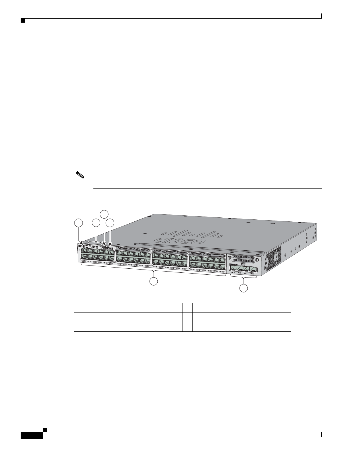
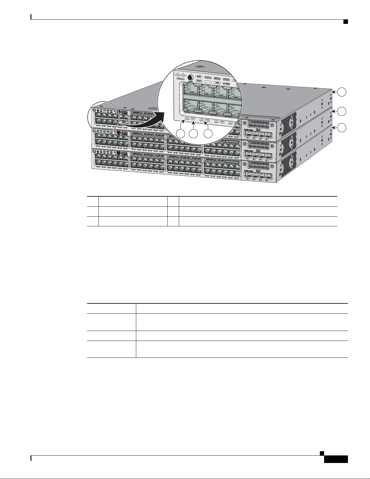
Figure 1-1 Catalyst 3850-48P-L Switch Front Panel
4
2
31
Catalyst 3850 48 PoE+
01X
12X
13X
24X
25X
36X
37X
48X
C3850-NM-4-1G
5
6
1 Mode button 4 USB mini-Type B (console) port
2 Status LEDs 5 10/100/1000 PoE+ Ethernet ports
3 USB Type A storage port 6 Network module
344175
Catalyst 3850 Switch Hardware Installation Guide
1-4
OL-26779-02
Page 15
Chapter 1 Product Overview
ACTV
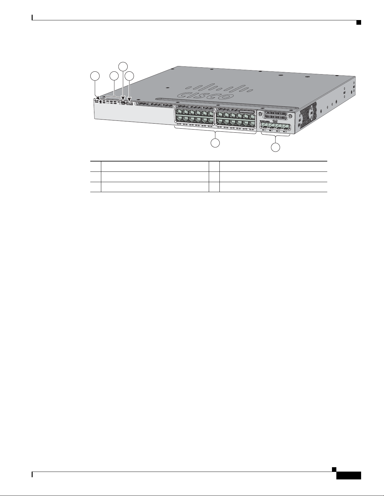
Figure 1-2 Catalyst 3850-24P-L Switch Front Panel
Front Panel
4
2
31
1 Mode button 4 USB mini-Type B (console) port
2 Status LEDs 5 10/100/1000 PoE+ Ethernet ports
3 USB Type A storage port 6 Network module
10/100/1000 Ethernet Ports
The 10/100/1000 Ethernet ports use RJ-45 connectors with Ethernet pinouts. The maximum cable length
is 328 feet (100 meters). The 100BASE-TX and 1000BASE-T traffic requires Category 5, Category 5e,
or Category 6 unshielded twisted pair (UTP) cable. The 10BASE-T traffic can use Category 3 or
Category 4 UTP cable.
For information about the 10/100/1000 Ethernet port connections and specifications, see the
“10/100/1000 Ethernet Port Connections” section on page 2-19 and Appendix B, “Connector and Cable
Specifications.”
Catalyst 3850 PoE+
01X
13X
24X
5
C3850-NM-4-1G
6
344514
PoE, PoE+, and Cisco UPOE Ports
The PoE+ and Cisco Universal Power Over Ethernet (Cisco UPOE) ports use the same connectors as
described in the “10/100/1000 Ethernet Ports” section on page 1-5.
They provide:
• PoE+ ports: Support for IEEE 802.3af-compliant powered devices (up to 15.4 W PoE per port) and
support for IEEE 802.3at-compliant powered devices (up to 30 W PoE+ per port). The maximum
total PoE power in a 1RU switch is 1800 W.
• Cisco UPOE ports: Support for powered devices on all four Ethernet signal pairs (up to 60 W Cisco
UPOE per port).
• Support for Cisco-enhanced PoE.
• Support for prestandard Cisco powered devices.
• Configuration for StackPower. When the switch internal power supply module(s) cannot support the
total load, StackPower configurations allow the switch to leverage power available from other
switches.
• Configurable support for Cisco intelligent power management, including enhanced power
OL-26779-02
negotiation, power reservation, and per-port power policing.
Catalyst 3850 Switch Hardware Installation Guide
1-5
Page 16

Front Panel
Depending on the installed power supply modules, each port can deliver up to 60 W of Cisco UPOE. See
Table 1-15 on page 1-19 for the power supply matrix that defines the available PoE, PoE+, and Cisco
UPOE power per port. The output of the PoE+ circuit has been evaluated as a Limited Power Source
(LPS) per IEC 60950-1.
Note For information about power supply modules, PoE+ port connections, and PoE+ specifications, see the
“Power Supply Modules” section on page 1-18, the “PoE+ and Cisco UPOE Port Connections” section
on page 2-20, and Appendix B, “Connector and Cable Specifications.”
Management Ports
• Ethernet management port (see the “Ethernet Management Port” section on page 1-23)
• RJ-45 console port (EIA/TIA-232) (see the “RJ-45 Console Port” section on page 1-23)
• USB mini-Type B console port (5-pin connector)
You can connect the switch to a host such as a Windows workstation or a terminal server through the
Ethernet management port, the RJ-45 console port, or the USB console port (USB mini-Type B port).
The USB console port connection uses a USB Type A to 5-pin mini-Type B cable. The USB console
interface speeds are the same as the RJ-45 console interface speeds.
Chapter 1 Product Overview
USB Mini-Type B Port
The switch provides a USB mini-Type B console connection on the front panel, and the RJ-45 console
port on the switch rear panel. Console output is always active on both connectors, but console input is
active on only one connector at a time, with the USB connector taking precedence over the RJ-45
connector.
Use a USB type-A-to-USB 5-pin mini-Type B cable to connect a PC or other device to the switch. The
required USB cable is included in the optional accessory kit.
The connected device must include a terminal emulation application.
Windows PCs need a driver for the USB port. See the “Installing the Cisco Microsoft Windows USB
Device Driver” section on page C-4 for installation instructions.
When the switch detects a valid USB connection to a powered device, input from the RJ-45 console port
is immediately disabled, and input from the USB console is enabled. Removing the USB connection
immediately reenables input from the Ethernet connection. An LED on the switch front panel (see
Figure 1-4) is green when the USB console connection is enabled.
The switch provides a configurable inactivity timeout that reactivates the RJ-45 console if no input
activity has occurred on the USB console for a specified time period. After the USB console has been
deactivated due to a timeout, you can restore its operation by disconnecting and reconnecting the USB
cable. You can disable USB console operation by using Cisco IOS commands. See the switch software
configuration guide for details.
Note The 4-pin mini-Type B connectors resemble 5-pin mini-Type B connectors. They are not compatible.
Use only the 5-pin mini-Type B. See Figure 1-3.
1-6
Catalyst 3850 Switch Hardware Installation Guide
OL-26779-02
Page 17

Chapter 1 Product Overview
Figure 1-3 USB Mini-Type B Port
You can use the command-line interface (CLI) to configure an inactivity timeout which reactivates the
RJ-45 console if the USB console has been activated and no input activity has occurred on the USB
console for a specified time period.
After the USB console deactivates due to inactivity, you cannot use the CLI to reactivate it. Disconnect
and reconnect the USB cable to reactivate the USB console. For information on using the CLI to
configure the USB console interface, see the switch software guide.
USB Type A Port
The USB Type A interface provides access to external USB flash devices (also known as thumb drives
or USB keys).
Front Panel
253163
The interface supports Cisco USB flash drives with capacities from 64 MB to 1 GB.
Cisco IOS software provides standard file system access to the flash device: read, write, erase, and copy,
as well as the ability to format the flash device with a FAT file system.
For more information about the switch management ports, see the switch software configuration guide
and the command reference on Cisco.com and the “Connector Specifications” section on page B-1.
Network Modules
The switch supports one hot-swappable network module that provides uplink ports to connect to other
devices. The switch should only be operated with either a network module or a blank module installed.
The switch generates logs when you insert or remove a network module with SFP ports.
OL-26779-02
Catalyst 3850 Switch Hardware Installation Guide
1-7
Page 18

Front Panel
Chapter 1 Product Overview
Table 1-2 Network Modules
Network Module
1
Description
C3850-NM-4-1G This module has four 1-Gigabit SFP module slots. Any combination of
standard SFP modules are supported. SFP+ modules are not supported.
If you insert an SFP+ module in the 1-Gigabit network module, the SFP+
module does not operate, and the switch logs an error message.
See Figure 3-1 on page 3-2.
C3850-NM-2-10G This module has four slots that support the following combinations:
• Two slots (left side) support only 1-Gigabit SFP modules and two slots
(right side) support either 1-Gigabit SFP or 10-Gigabit SFP modules.
• Three slots (left side) support 1-Gigabit SFP modules and one slot (right
side) supports 10-Gigabit Ethernet SFP+.
Supported combinations of SFP and SFP+ modules:
• Slots 1, 2, 3, and 4 populated with 1-Gigabit SFP modules.
• Slots 1 and 2 populated with 1-Gigabit SFP modules and Slot 4 populated
with one 10-Gigabit SFP+ module.
• Slot 3 and Slot 4 each populated with 10-Gigabit SFP+ modules.
See Figure 3-2 on page 3-2.
C3850-NM-4-10G This module has four 10-Gigabit slots or four 1-Gigabit slots.
Note This is only supported on the 48-port models.
C3850-NM-BLANK This module has no uplink ports.
1. All network modules are hot-swappable.
For information about the network modules, see the “Installing a Network Module in the Switch” section
on page 2-19. For cable specifications, see Appendix B, “Connector and Cable Specifications.”
SFP and SFP+ Modules
The SFP and SFP+ modules provide copper or fiber-optic connections to other devices. These
transceiver modules are field-replaceable, and they provide the uplink interfaces when installed in an
SFP module slot. The SFP modules have LC connectors for fiber-optic connections or RJ-45 connectors
for copper connections.
Use only Cisco SFP and SFP+ modules on the switch. For the latest information about supported SFP
and SFP+ modules, refer to the Cisco Transceiver Modules Compatibility Information at:
http://www.cisco.com/en/US/products/hw/modules/ps5455/products_device_support_tables_list.html
For information about SFP modules, see the SFP module documentation and the “Installing SFP and
SFP+ Modules” section on page 3-9. For cable specifications, see Appendix B, “Connector and Cable
Specifications.”
The Catalyst 3850 switch supports the SFP module patch cable (CAB-SFP-50CM), a 0.5-meter, copper,
passive cable with SFP module connectors at each end. This cable is only used with 1-Gigabit Ethernet
SFP ports to connect two Catalyst 3850 switches in a cascaded configuration.
See Figure 3-3 on page 3-3.
1-8
Catalyst 3850 Switch Hardware Installation Guide
OL-26779-02
Page 19
Chapter 1 Product Overview
LEDs
Front Panel
You can use the switch LEDs to monitor switch activity and its performance. Figure 1-4 shows the switch
LEDs and the Mode button that you use to select a port mode.
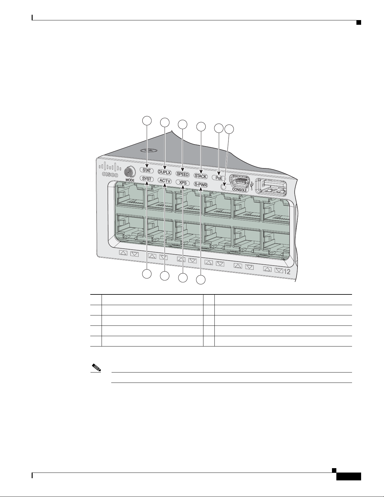
Figure 1-4 Switch Front Panel LEDs
1
2
3
4
5
6
01X
7
8
9
10
1 STAT (status) 6
CONSOLE (USB mini-Type B (console) port
344176
2 DUPLX (duplex) 7 SYST (system)
3 SPEED 8 ACTV (active)
4 STACK 9 XPS
5 PoE
1. The XPS 2200 is not supported in this release.
2. Only switches with PoE+ ports.
Note The Catalyst 3850 switches might have slight cosmetic differences on the bezels.
2
10 S-PWR (StackPower)
1
(Expandable power system)
OL-26779-02
Catalyst 3850 Switch Hardware Installation Guide
1-9
Page 20

Front Panel
SYST LED
Chapter 1 Product Overview
Table 1-3 SYST LED
Color System Status
Off System is not powered on.
Green System is operating normally.
Blinking Green Switch is running POST.
Blinking Amber There is a fault with one of the following:
• Network module (non-traffic-related)
• Power supply
• Fan module
Amber System is receiving power but is not functioning
properly.
For information on the SYST LED colors during POST, see the “Diagnosing Problems” section on
page 6-1.
XPS LED
Note The XPS 2200 is not supported in this release.
Ta b le 1 - 4 X P S L ED
Color XPS Status
Off XPS cable is not installed.
Switch is in StackPower mode.
Green XPS is connected and ready to provide back-up power.
Blinking green XPS is connected but is unavailable because it is providing power to another device
(redundancy has been allocated to a neighboring device).
Amber The XPS is in standby mode or in a fault condition. See the XPS 2200
documentation for information about the standby mode and fault conditions.
Blinking amber The power supply in a switch has failed, and the XPS is providing power to that
switch (redundancy has been allocated to this device).
For information about the XPS 2200, see the Cisco eXpandable Power System 2200 Hardware
Installation Guide on Cisco.com:
http://www.cisco.com/go/xps2200_hw
1-10
Catalyst 3850 Switch Hardware Installation Guide
OL-26779-02
Page 21

Chapter 1 Product Overview
Port LEDs and Modes
Each Ethernet port, 1-Gigabit Ethernet module slot, and 10-Gigabit Ethernet module slot has a port LED.
These port LEDs, as a group or individually, display information about the switch and about the
individual ports. The port mode determines the type of information shown by the port LEDs. Ta ble 1-5
lists the mode LEDs and their associated port modes and meanings.
To select or change a mode, press the Mode button until the desired mode is highlighted. When you
change port modes, the meanings of the port LED colors also change. Ta ble 1-6 explains how to interpret
the port LED colors in different port modes.
When you press the Mode button on any switch in the switch stack, all the stack switches change to show
the same selected mode. For example, if you press the Mode button on the active switch to show the
SPEED LED, all the other switches in the stack also show the SPEED LED.
Table 1-5 Port Mode LEDs
Mode LED Port Mode Description
STAT Port status The port status. This is the default mode.
SPEED Port speed The port operating speed: 10, 100, or 1000 Mb/s.
DUPLX Port duplex mode The port duplex mode: full duplex or half duplex.
ACTV Active The active switch status.
STACK Stack member status
Front Panel
The stack member status.
StackWise port status
The StackWise port status. See the “STACK LED” section on
page 1-14.
1
PoE
1. Only switches with PoE+ ports.
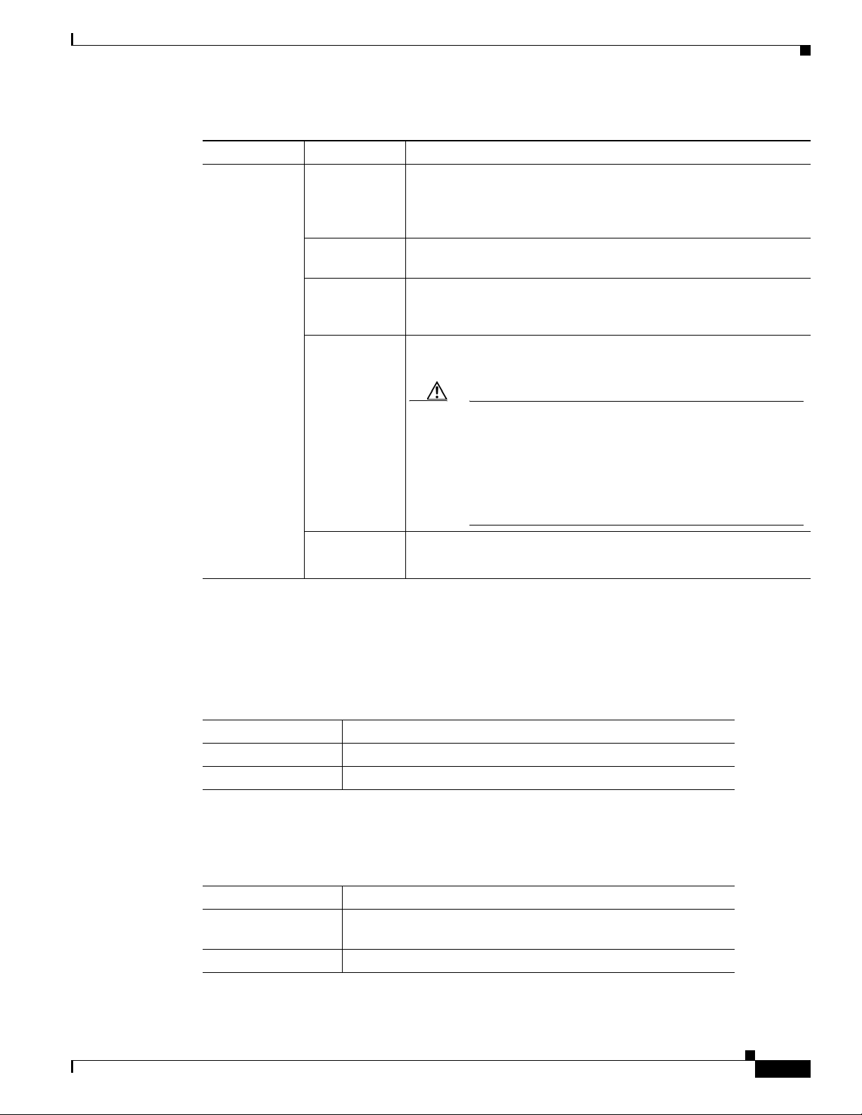
Table 1-6 Meaning of Switch LED Colors in Different Modes
PoE+ port power The PoE+ port status.
Port Mode Port LED Color Meaning
STAT
(port status)
Off No link, or port was administratively shut down.
Green Link present, no activity.
Blinking green Activity. Port is sending or receiving data.
Alternating
green-amber
Link fault. Error frames can affect connectivity, and errors such as
excessive collisions, CRC errors, and alignment and jabber errors
are monitored for a link-fault indication.
Amber Port is blocked by Spanning Tree Protocol (STP) and is not
forwarding data.
After a port is reconfigured, the port LED can be amber for up to 30
seconds as STP checks the switch for possible loops.
OL-26779-02
Catalyst 3850 Switch Hardware Installation Guide
1-11
Page 22

Front Panel
Chapter 1 Product Overview
Table 1-6 Meaning of Switch LED Colors in Different Modes (continued)
Port Mode Port LED Color Meaning
SPEED
DUPLX
(duplex)
ACTV
(data active
switch)
STACK
(stack member)
10/100/1000/SFP ports
Off Port is operating at 10 Mb/s.
Green Port is operating at 100 Mb/s.
Single green
Port is operating at 1000 Mb/s.
flash (on for
100 ms, off for
1900 ms)
Network module slots
Off Port is not operating.
Blinking green Port is operating at up to 10 Gb/s.
Off Port is operating in half duplex.
Green Port is operating in full duplex.
Off The switch is not the active switch.
Note For a standalone switch, this LED is off.
Green The switch is the active switch.
Amber Error during active switch election.
Blinking green Switch is a standby member of a data stack and assumes active
responsibilities if the current active switch fails.
Off No stack member corresponding to that member number.
Blinking green Stack member number.
Green Member numbers of other stack member switches.
1-12
Catalyst 3850 Switch Hardware Installation Guide
OL-26779-02
Page 23
Chapter 1 Product Overview
Table 1-6 Meaning of Switch LED Colors in Different Modes (continued)
Port Mode Port LED Color Meaning
PoE+
Front Panel
1
Off PoE+ is off.
If the powered device is receiving power from an AC power source,
the port LED is off even if the device is connected to the switch port.
Green PoE+ is on. The port LED is green when the switch port is providing
power.
Alternating
green and
PoE+ is denied because providing power to the powered device will
exceed the switch power capacity.
amber
Blinking amber PoE+ is off due to a fault or because it has exceeded a limit set in
the switch software.
Caution PoE+ faults occur when noncompliant cabling or
powered devices are connected to a PoE+ port. Use only
standard-compliant cabling to connect Cisco prestandard
IP Phones and wireless access points or
IEEE 802.3af-compliant devices to PoE+ ports. You
must remove from the network any cable or device that
causes a PoE+ fault.
USB Console LED
S-PWR LED
Amber PoE+ for the port has been disabled.
Note PoE+ is enabled by default.
1. Only switches with PoE or PoE+ ports.
The USB console LED (Figure 1-4) shows whether there is an active USB connection to the port.
Table 1-7 USB Console Port LED
Color Description
Off USB console is disabled.
Green USB console is enabled.
Table 1-8 S-PWR LED
Color Description
Off StackPower cable is not connected, or the switch is in standalone
mode.
Green Each StackPower port is connected to another switch.
OL-26779-02
Catalyst 3850 Switch Hardware Installation Guide
1-13
Page 24

Front Panel
ACTV LED
Chapter 1 Product Overview
Table 1-8 S-PWR LED
Color Description
Blinking Green This appears on the switch in a StackPower ring configuration
that detects an open ring or has only one StackPower cable
connected.
Amber There is a fault: load shedding is occurring, a StackPower cable
is defective, or administrative action is required. See the switch
software configuration guide for information about configuring
StackPower.
Blinking Amber The StackPower budget is not sufficient to meet current power
demands.
Ta b le 1 - 9 A C TV LE D
Color Description
Off Switch is not the active switch.
Green Switch is the active switch or a standalone switch.
Amber An error occurred when the switch was selecting the active
switch, or another type of stack error occurred.
Slow blinking green Switch is in stack standby mode.
STACK LED
The STACK LED shows the sequence of member switches in a stack. Up to four switches can be
members of a stack. The first four port LEDs show the member number of a switch in a stack. Figure 1-5
shows the LEDs on the first switch, which is stack member number 1. For example, if you press the Mode
button and select Stack, the LED for port 1 blinks green. The LEDs for ports 2 and 3 are solid green, as
these represent the member numbers of other switches in the stack. The other port LEDs are off because
there are no more members in the stack.
1-14
Catalyst 3850 Switch Hardware Installation Guide
OL-26779-02
Page 25
Chapter 1 Product Overview
01X
ACTV
AC
T
V
Figure 1-5 STACK LED
Front Panel
1
2
PoE LED
01X
01X
01X
12X
13X
12X
13X
12X
13X
24X
25X
24X
25X
24X
25X
64
5
36X
37X
36X
37X
Catalyst 3850 48 PoE+
Catalyst 3850 48 PoE+
48X
48X
48X
C3850-NM-4-1G
C3850-NM-4-1G
C3850-NM-4-1G
3
1 Stack member 1 4 LED blinks green to show that this is switch 1 in the stack.
2 Stack member 2 5 LED is solid green to show that switch 2 is a stack member.
3 Stack member 3 6 LED is solid green to show that switch 3 is a stack member.
When you select the STACK LED mode, the representative STACK LEDs are green when the StackWise
ports are up, and the representative STACK LEDs are amber when the ports are down.
The PoE LED indicates the status of the PoE mode: either PoE, PoE+, or Cisco UPOE.
Table 1-10 PoE LED Status
344178
Color Status of PoE mode (PoE, PoE+, or Cisco UPOE)
Off PoE mode is not selected. None of the 10/100/1000 ports have been denied power
or are in a fault condition.
Green PoE mode is selected, and the port LEDs show the PoE mode status.
Blinking amber PoE mode is not selected. At least one of the 10/100/1000 ports has been denied
power, or at least one of the 10/100/1000 ports has a PoE mode fault.
OL-26779-02
Catalyst 3850 Switch Hardware Installation Guide
1-15
Page 26
Front Panel
344177
1
2
3
4
C3850-NM-4-1G
Catalyst 3850 48 PoE+
Network Module LEDs
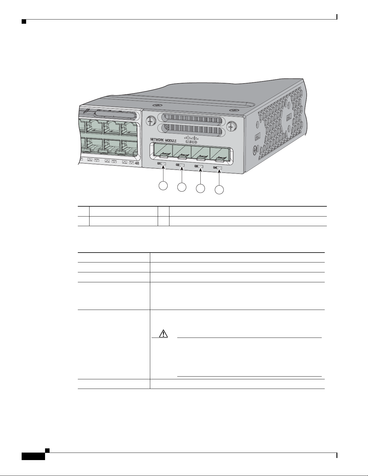
Figure 1-6 Network Module LEDs
Chapter 1 Product Overview
1 G1 LED 3 G3 LED
2 G2 LED 4 G4 LED
Table 1-11 Network Module LEDs
Color Network Module Link Status
Off Link is off.
Green Link is on; no activity.
Blinking green Activity on a link; no faults.
Note The LED will blink green even when there is very little
control traffic.
Blinking amber Link is off due to a fault or because it has exceeded a limit set in the
switch software.
Caution Link faults occur when noncompliant cabling is
connected to an SFP or SFP+ port. Use only
standard-compliant cabling to connect to Cisco SFP and
SFP+ ports. You must remove from the network any cable
or device that causes a link fault.
Amber Link for the SFP or SFP+ has been disabled.
1-16
Catalyst 3850 Switch Hardware Installation Guide
OL-26779-02
Page 27
Chapter 1 Product Overview
CONSOLE
MGMT
MGMT
344179
1
2
105
8
5
1196 6 7
109
11
PWR-C1-715WAC
PWR-C1-715WAC
3
4
5
Rear Panel
Rear Panel
The switch rear panel includes StackWise connectors, StackPower connectors, ports, fan modules, and
power supply modules. See Figure 1-7.
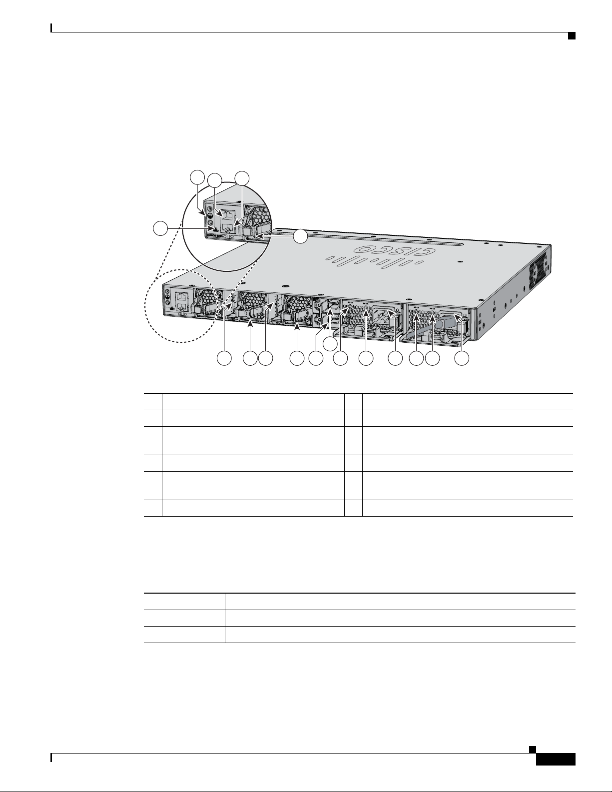
Figure 1-7 Catalyst 3850 Switch Rear Panel
1 Ground connector 7 StackPower connector
2 CONSOLE (RJ-45 console port) 8 StackPower connector
3 MGMT (RJ-45 10/100/1000 management
9 AC OK (input) status LED
port)
4 RESET button 10 PS OK (output) status LED
5 Fan module 11 Power supply modules (AC power supply
modules shown)
6 StackWise port connector
RJ-45 Console Port LED
Table 1-12 RJ-45 Console Port LED
Color RJ-45 Console Port Status
Off RJ-45 console is disabled. USB console is active.
Green RJ-45 console is enabled. USB console is disabled.
OL-26779-02
Catalyst 3850 Switch Hardware Installation Guide
1-17
Page 28

Rear Panel
StackWise Ports
StackWise ports are used to connect switches in StackWise stacking configurations. The Catalyst 3850
switch ships with a 0.5-meter StackWise cable that you can use to connect the StackWise ports. For more
information on StackWise cables, see StackWise Cables, page B-5.
Caution Use only approved cables, and connect only to similar Cisco equipment. Equipment might be damaged
if connected to nonapproved Cisco cables or equipment.
Power Supply Modules
The 24- and 48-port switches are powered through one or two internal power supply modules.
Supported power supply modules:
• PWR-C1-350WAC
• PWR-C1-715WAC
Chapter 1 Product Overview
• PWR-C1-1100WAC
• PWR-C1-440WDC
The switch has two internal power supply module slots. You can use two AC modules, two DC modules,
a mixed configuration of one AC and one DC power supply module, or one power supply module and a
blank module.
The switch can operate with either one or two active power supply modules or with power supplied by
a stack. A Catalyst 3850 switch that is in a StackPower stack can operate with power supplied by other
switches in the stack.
Table 1-1 show the default power supply modules that ship with each switch model. All power supply
modules (except the blank modules) have internal fans. All switches ship with a blank power supply
module in the second power supply slot.
Caution Do not operate the switch with one power supply module slot empty. For proper chassis cooling, both
power supply module slots must be populated with either a power supply or a blank module.
The 350-W and 715-W AC power supply modules are autoranging units that support input voltages
between 100 and 240 VAC. The 1100-W power supply module is an autoranging unit that supports input
voltages between 115 and 240 VAC. The 440-W DC power supply module has dual input feeds (A and B)
and supports input voltages between 36 and 72 VDC. The output voltage range is 51–57 V.
Each AC power supply module has a power cord for connection to an AC power outlet. The 1100-W and
715-W modules use a 16-AWG cord (only North America). All other modules use an 18-AWG cord. The
DC-power supply module must be wired to a DC-power source.
1-18
Table 1-1 3 , Tabl e 1 -14, and Tab l e 1 - 15 shows the PoE available and PoE requirements for Catalyst 3850
switches.
Catalyst 3850 Switch Hardware Installation Guide
OL-26779-02
Page 29
Chapter 1 Product Overview
Table 1-13 Available PoE with AC Power Supply
Models Default Power Supply Available PoE
24-port data switch PWR-C1-350WAC —
48-port data switch
24-port PoE switch PWR-C1-715WAC 435 W
48-port PoE+ switch
48-port full PoE+ switch PWR-C1-1100WAC 800 W
24-port Cisco UPOE
switch
48-port Cisco UPOE
switch
Table 1-14 Available PoE with DC Power Supply
Rear Panel
PWR-C1-1100WAC 800 W
Number of Power
Models
Supplies Available PoE
24-port PoE+ switch 1 220 W
2660 W
48-port PoE+ switch 1 185 W
2625 W
24-port Cisco UPOE
switch
48-port Cisco UPOE
switch
Table 1-15 Switch Power Supply Requirements for PoE, PoE+, and Cisco UPOE
PoE Option 24-Port Switch 48-Port Switch
PoE (up to 15.4 per
port)
1220 W
2660 W
1185 W
2625 W
1
(1) 715-W These are the combinations of power
supplies:
• (1) 1100-W
• (1) 715-W + (1) 715-W
OL-26779-02
Catalyst 3850 Switch Hardware Installation Guide
1-19
Page 30

Rear Panel
Chapter 1 Product Overview
Table 1-15 Switch Power Supply Requirements for PoE, PoE+, and Cisco UPOE (continued)
PoE Option 24-Port Switch 48-Port Switch
PoE+ (up to 30 W per
ports
Cisco UPOE (up to 60
W per port)
These are the combinations of
power supplies:
• (1) 1100-W
• (1) 715-W 715-W
(2) 1100-W These are the combinations of power
These are the combinations of power
supplies:
• (1) 1100-W + (1) 715-W
• (2) 1100-W
supplies:
1
(1) 1100-W + (1) 715-W
(2) 1100-W
Note Up to 30 PoE ports can receive
full Cisco UPOE.
1. A 48-port switch with one 715-W power supply provides up to 8.7 W of PoE to all ports.
1-20
Catalyst 3850 Switch Hardware Installation Guide
OL-26779-02
Page 31

Chapter 1 Product Overview
The power supply modules have two status LEDs.
Table 1-16 Switch Power Supply Module LEDs
AC-Power Supply Module LEDs
AC OK Description PS OK Description
Off No AC input power. Off Output is disabled, or input is
Green AC input power present. Green Power output to switch active.
DC-Power Supply Module LEDs
DC OK Description PS OK Description
Off No DC input power. Off Output is disabled, or input is
Green DC input power present. Green Power output to switch active.
Rear Panel
outside operating range (AC LED
is off).
Red Output has failed.
outside operating range (DC LED
is off).
Red Output has failed.
Fan Modules
Note Three fans are required for proper cooling.
For information about replacing a power supply module, wiring a DC power supply module, and module
specifications, see Chapter 4, “Power Supply Installation,” and Appendix A, “Technical Specifications.”
The switch has three internal hot-swappable 12-V fan modules. The air circulation system consists of
the fan modules and the power supply modules. The airflow patterns vary depending on the power supply
configuration.
Figure 1-8 shows the airflow patterns for the 24- and 48-port switches. The blue arrow shows cool air
flow, and the red arrow shows warm air flow. When the fan modules are operating properly, a green LED
is on at the top left corner of the fan assembly (viewed from the rear). If the fan fails, the LED turns to
amber. The switch can operate with two operational fans, but the failed fan should be replaced as soon
as possible to avoid a service interruption due to a second fan fault.
OL-26779-02
Catalyst 3850 Switch Hardware Installation Guide
1-21
Page 32

Rear Panel
C
a
t
al
yst
3650
24P
oE
+
4X
1G
344180
Catalys
t 3850 48 PoE+
01X
13X
12X
24X
25X
36X
37X
48X
A
CT
V
Chapter 1 Product Overview
Table 1-17 Switch Fan Module
Fan Module Description
FAN-T1= Fan Module
Figure 1-8 24- and 48-Port Switch Airflow Patterns
For information about installing a fan module and fan specifications, see Chapter 5, “Installing the Fan,”
and Appendix A, “Technical Specifications.”
StackPower Connector
The Catalyst 3850 switches have a StackPower connector for use with Cisco StackPower cables to
configure a switch power stack that includes up to four switches. A switch power stack can be configured
in redundant or power-sharing mode.
You can order these StackPower cables from your Cisco sales representative:
• CAB-SPWR-30CM (0.3-meter cable)
• CAB-SPWR-150CM (1.5-meter cable)
For details about connecting StackPower cables and StackPower guidelines, see the “Planning a
StackPower Stack” section on page 2-8.
1-22
Catalyst 3850 Switch Hardware Installation Guide
OL-26779-02
Page 33

Chapter 1 Product Overview
Management Ports
Ethernet Management Port
You can connect the switch to a host such as a Windows workstation or a terminal server through the
10/100/1000 Ethernet management port or one of the console ports (see Figure 1-7). The 10/100/1000
Ethernet management port is a VPN routing/forwarding (VRF) interface and uses a RJ-45 crossover or
straight-through cable.
Table 1-1 8 shows the Ethernet management port LED colors and their meanings.
Table 1-18 Ethernet Management Port LED
Color Description
Green Link up but no activity.
Blinking green Link up and activity.
Off Link down.
Management Options
RJ-45 Console Port
The RJ-45 console port connection uses the supplied RJ-45-to-DB-9 female cable.
Table 1-1 9 shows the RJ-45 console port LED colors and their meanings.
Table 1-19 RJ-45 Console LEDs
Color Description
Green RJ-45 console port is active.
Off The port is not active.
Management Options
• Cisco Network Assistant
Cisco Network Assistant is a PC-based network management GUI application for LANs. You can
use the GUI to configure and manage switch clusters or standalone switches. Cisco Network
Assistant is available at no cost and can be downloaded from this URL:
http://www.cisco.com/pcgi-bin/tablebuild.pl/NetworkAssistant
For information on starting the Network Assistant application, see the Getting Started with Cisco
Network Assistant guide on Cisco.com.
• Cisco IOS CLI
OL-26779-02
You can configure and monitor the switch and switch cluster members from the CLI. You can access
the CLI by connecting your management station directly to the switch console port or by using
Telnet from a remote management station. See the switch command reference on Cisco.com for
more information.
Catalyst 3850 Switch Hardware Installation Guide
1-23
Page 34

Management Options
• Cisco Prime Infrastructure
Cisco Prime Infrastructure combines the wireless functionality of Cisco Prime Network Control
System (NCS) and the wired functionality of Cisco Prime LAN Management Solution (LMS), with
application performance monitoring and troubleshooting capabilities of Cisco Prime Assurance
Manager. For more information, see the Cisco Prime Infrastructure documentation on Cisco.com.
http://www.cisco.com/en/US/products/ps12239/index.html
Network Configurations
See the switch software configuration guide on Cisco.com for network configuration concepts and
examples of using the switch to create dedicated network segments and interconnecting the segments
through Gigabit Ethernet connections.
Chapter 1 Product Overview
1-24
Catalyst 3850 Switch Hardware Installation Guide
OL-26779-02
Page 35

CHAP T E R
2
Switch Installation
This chapter describes how to install and connect a Catalyst 3850 switch. It also includes planning and
cabling considerations for stacking switches. Read the topics and perform the procedures in this order:
• Preparing for Installation, page 2-1
• Planning a Switch Data Stack, page 2-4
• Planning a StackPower Stack, page 2-8
• Installing the Switch, page 2-11
• Connecting to the StackWise Ports, page 2-17
• Installing a Network Module in the Switch, page 2-19
• Connecting Devices to the Ethernet Ports, page 2-19
• Where to Go Next, page 2-21
For initial switch setup, how to assign the switch IP address, and for powering information, see the
Catalyst 3850 Switch Getting Started Guide on Cisco.com.
Preparing for Installation
• Safety Warnings, page 2-1
• Installation Guidelines, page 2-3
• Tools and Equipment, page 2-4
Safety Warnings
This section includes the basic installation caution and warning statements. Translations of the warning
statements appear in the Regulatory Compliance and Safety Information for the Catalyst 3850 Switch
document available at Cisco.com. Read this section before you start the installation procedure.
Warning
OL-26779-02
Before working on equipment that is connected to power lines, remove jewelry (including rings,
necklaces, and watches). Metal objects will heat up when connected to power and ground and can
cause serious burns or weld the metal object to the terminals.
Statement 43
Catalyst 3850 Switch Hardware Installation Guide
2-1
Page 36

Preparing for Installation
Chapter 2 Switch Installation
Warning
Warning
Warning
Warning
Warning
Warning
Do not stack the chassis on any other equipment. If the chassis falls, it can cause severe bodily injury
and equipment damage.
Ethernet cables must be shielded when used in a central office environment.
Statement 48
Statement 171
Voice over IP (VoIP) service and the emergency calling service do not function if power fails or is
disrupted. After power is restored, you might have to reset or reconfigure equipment to regain access
to VoIP and the emergency calling service. In the USA, this emergency number is 911. You need to be
aware of the emergency number in your country.
Statement 361
If a Cisco external power system is not connected to the switch, install the provided connector cover
on the back of the switch.
Statement 386
Do not work on the system or connect or disconnect cables during periods of lightning activity.
Statement 1001
Read the installation instructions before connecting the system to the power source.
Statement 1004
Warning
Warning
Warning
Warning
Warning
Warning
This unit is intended for installation in restricted access areas. A restricted access area can be
accessed only through the use of a special tool, lock and key, or other means of security.
Statement 1017
The plug-socket combination must be accessible at all times, because it serves as the main
disconnecting device.
Use copper conductors only.
Statement 1019
Statement 1025
This unit might have more than one power supply connection. All connections must be removed to
de-energize the unit.
Statement 1028
Only trained and qualified personnel should be allowed to install, replace, or service this equipment.
Statement 1030
Ultimate disposal of this product should be handled according to all national laws and regulations.
Statement 1040
2-2
Catalyst 3850 Switch Hardware Installation Guide
OL-26779-02
Page 37

Chapter 2 Switch Installation
Preparing for Installation
Warning
Warning
Warning
Warning
Note The grounding architecture of this product is DC-isolated (DC-I).
For connections outside the building where the equipment is installed, the following ports must be
connected through an approved network termination unit with integral circuit protection: 10/100/1000
Ethernet.
To prevent the system from overheating, do not operate it in an area that exceeds the maximum
recommended ambient temperature of:
113°F (45°C)
Installation of the equipment must comply with local and national electrical codes.
To prevent airflow restriction, allow clearance around the ventilation openings to be at least:
3 in. (7.6 cm)
Statement 1044
Installation Guidelines
Statement 1047
Statement 1074
Statement 1076
Before installing the switch, verify that these guidelines are met:
• Clearance to front and rear panels requires that
–
Front-panel indicators can be easily read.
–
Clearance is at least 4.4 in. (11.1 cm) from switch rear panel.
–
Access to ports is sufficient for unrestricted cabling.
–
AC power cord can reach from the AC power outlet to the connector on the switch rear panel.
–
The SFP or SFP+ module minimum bend radius and connector length is met. See the SFP or
SFP+ module documentation for more information.
• For switches with the optional 1100-W power-supply module (PWR-C1-1100WAC=), first
rack-mount the switch before installing the power-supply module.
• Make sure power-supply modules and fan modules are securely inserted in the chassis before
moving the switch.
• When connecting or disconnecting the power cord on a switch that is installed above or below a
1100-W power supply-equipped switch, you might need to remove the module from the switch to
access the power cord.
• Cabling is away from sources of electrical noise, such as radios, power lines, and fluorescent
lighting fixtures. Make sure that the cabling is safely away from other devices that might damage
the cables.
OL-26779-02
Catalyst 3850 Switch Hardware Installation Guide
2-3
Page 38

Planning a Switch Data Stack
• For copper connections on Ethernet ports, cable lengths from the switch to connected devices can
be up to 328 feet (100 meters).
• For cable requirements for SFP+ module connections, see the “Cable and Adapter Specifications”
section on page B-5. Each port must match the wave-length specifications on the other end of the
cable, and the cable must not exceed the minimum cable length.
• Operating environment is within the ranges listed in Appendix A, “Technical Specifications.”
• Airflow around the switch and through the vents is unrestricted.
• Temperature around the unit does not exceed 113°F (45°C). If the switch is installed in a closed or
multirack assembly, the temperature around it might be greater than normal room temperature.
• Cisco Ethernet switches are equipped with cooling mechanisms, such as fans and blowers. However,
these fans and blowers can draw dust and other particles, causing contaminant buildup inside the
chassis, which can result in system malfunction. You must install this equipment in an environment
as free from dust and foreign conductive material (such as metal flakes from construction activities)
as is possible.
Tools and Equipment
Chapter 2 Switch Installation
You need to supply a number-2 Phillips screwdriver to rack-mount the switch, to install network
modules, and to install StackPower cables.
Verifying Switch Operation
Before you install the switch in a rack, or on a table or shelf, you should power on the switch and verify
that the switch passes POST. See the “Running Express Setup” section in the getting started guide for
the steps required to connect a PC to the switch and to run Express Setup.
Powering Off the Switch
After a successful POST, disconnect the power cord from the switch. Install the switch in a rack, on a
table, or on a shelf as described in the Chapter 2, “Installing the Switch,” section.
Planning a Switch Data Stack
Catalyst 3850 switches can share bandwidth by using data stacking.
• Switch Stacking and Power Stacking Guidelines, page 2-5
• Data Stack Cabling Configurations, page 2-5
• Data Stack Bandwidth and Partitioning Examples, page 2-6
• Installing the Switch, page 2-11
2-4
Catalyst 3850 Switch Hardware Installation Guide
OL-26779-02
Page 39

Chapter 2 Switch Installation
Switch Stacking and Power Stacking Guidelines
For general concepts and management procedures for switch stacks, see the switch software
configuration guide on Cisco.com.
Before connecting the switches in a stack, keep in mind these stacking guidelines:
• Size of the switch and any optional power-supply module. The 1100-W power-supply module is
longer than the other modules. Stacking switches with the same power-supply modules together
makes it easier to cable the switches. For switch dimensions, see Appendix A, “Technical
Specifications.”
• Length of cable. Depending on the configurations that you have, you might need different-sized
cables. If you do not specify the length of the StackWise cable, the 0.5-meter cable is supplied. If
you need the 1-meter cable or the 3-meter cable, you can order it from your Cisco supplier. For cable
part numbers, see the “StackWise Ports” section on page 1-18. The “Data Stack Cabling
Configurations” section on page 2-5 provides examples of recommended configurations.
• For rack-mounted switch stacks that are members of a StackPower stack as well as a data stack, see
the “Planning a StackPower Stack” section on page 2-8.
• You can create data stacks with up to four switches in a stack.
Data Stack Cabling Configurations
Data Stack Cabling Configurations
Figure 2-1 is an example of a recommended configuration that uses the supplied 0.5-meter StackWise
cable. In this example, the switches are stacked in a vertical rack or on a table. This configuration
provides redundant connections.
The configuration example (Figure 2-1) uses the supplied 0.5-meter StackWise cable. The example
shows the full-ring configuration that provides redundant connections.
Figure 2-1 Data Stacking the Catalyst 3850 Switches in a Rack or on a Table Using the 0.5-meter
StackWise Cables
CONSOLE
MGMT
CONSOLE
MGMT
CONSOLE
MGMT
CONSOLE
MGMT
PWR-C1-715WAC PWR-C1-715WAC
PWR-C1-715WAC PWR-C1-715WAC
PWR-C1-715WAC PWR-C1-715WAC
PWR-C1-715WAC PWR-C1-715WAC
334340
OL-26779-02
Figure 2-2 shows a recommended configuration when the switches are mounted side-by-side. Use the
1-meter and the 3-meter StackWise cables to connect the switches. This configuration provides
redundant connections.
Catalyst 3850 Switch Hardware Installation Guide
2-5
Page 40

Data Stack Cabling Configurations
Figure 2-2 Data Stacking up to Four Switches in a Side-by-Side Mounting
Data Stack Bandwidth and Partitioning Examples
This section provides examples of data stack bandwidth and possible data stack partitioning.
Figure 2-3 shows a data stack of Catalyst 3850 switches that provides full bandwidth and redundant
StackWise cable connections.
Figure 2-3 Example of a Data Stack with Full Bandwidth Connections
Chapter 2 Switch Installation
344183
1
2
3
344184
Figure 2-4 shows an example of a stack of Catalyst 3850 switches with incomplete StackWise cabling
connections. This stack provides only half bandwidth and does not have redundant connections.
Figure 2-4 Example of a Data Stack with Half Bandwidth Connections
1
2
344185
2-6
Catalyst 3850 Switch Hardware Installation Guide
OL-26779-02
Page 41

Chapter 2 Switch Installation
Figure 2-5 and Figure 2-6 show data stacks of Catalyst 3850 switches with failover conditions. In
Figure 2-5, the StackWise cable is bad in link 2. Therefore, this stack provides only half bandwidth and
does not have redundant connections. In Figure 2-6, link 2 is bad. Therefore, this stack partitions into
two stacks, and the top and bottom switches become the active switch in the stack. If the bottom switch
is a member (not active or standby switch), it reloads.
Figure 2-5 Example of a Data Stack with a Failover Condition
Data Stack Cabling Configurations
1
2
3
Figure 2-6 Example of a Partitioned Data Stack with a Failover Condition
1
2
Power-On Sequence for Switch Data Stacks
Consider these guidelines before you power on the switches in a stack:
• The sequence in which the switches are first powered on might affect the switch that becomes the
active switch and the standby switch.
• There are two ways to elect an active switch:
–
If you want a particular switch to become the active switch, configure it with the highest
priority. Among switches with same priority, the switch with the lowest MAC address becomes
the active switch.
344186
344187
OL-26779-02
–
If you want a particular switch to become the active switch, power on that switch first. This
switch remains the active switch until a reelection is required. After 2 minutes, power on the
other switches in the stack. If you have no preference as to which switch becomes the active
switch, power on all the switches in the stack within 1 minute. These switches participate in the
active switch election. Switches powered on after 2 minutes do not participate in the election.
If changes are made to the stack without powering down the switches, the following results can occur:
• If two operating partial ring stacks are connected together using a stack cable, a stack merge can
take place. This situation reloads the whole stack (all switches in the stack).
Catalyst 3850 Switch Hardware Installation Guide
2-7
Page 42

Planning a StackPower Stack
• If some switches in the stack are completely separated from the stack, a stack split can take occur.
• A stack split can occur on a full ring stack if:
• A stack split can occur in a partial ring stack if:
• In a split stack, depending on where the active and standby switches are located, either two stacks
Note These results depend on how the switches are connected. You can remove two or more switches
For conditions that can cause a stack reelection or to manually elect the active switch, see the stacking
software configuration guide on Cisco.com at this URL:
http://www.cisco.com/go/cat3850_docs
Chapter 2 Switch Installation
–
More than one running switch is removed without powering down.
–
More than one stack cable is removed without powering down.
–
A switch is removed without powering down.
–
A stack cable is removed without powering down.
might be formed (with the standby taking over as the new active switch in the newly formed stack)
or all the members in the newly formed stack might reload.
from the stack without splitting the stack.
Planning a StackPower Stack
Catalyst 3850 switches can share power by using the StackPower feature.
• StackPower Stacking Guidelines, page 2-8
• StackPower Cabling Configurations, page 2-9
StackPower Stacking Guidelines
You can configure a StackPower stack for either power sharing or redundancy. In power-sharing mode,
the power of all the power supplies in the stack is aggregated and distributed among the stack members.
In redundant mode, when the total power budget of the stack is calculated, the wattage of the largest
power supply is not included. That power is held in reserve and used to maintain power to switches and
attached devices when one power supply fails. Following the failure of a power supply, the StackPower
mode becomes power sharing.
Note Power-sharing mode is the recommended configuration for Catalyst 3850 switches.
For general concepts and management procedures for switch power stacks, see the software stacking
configuration guide on Cisco.com.
Before connecting the switches in a power stack, keep in mind these guidelines:
2-8
Catalyst 3850 Switch Hardware Installation Guide
OL-26779-02
Page 43
Chapter 2 Switch Installation
253393
• Size of the switch and any optional power supply module. The 1100-W power-supply module is
1.5 inches (3.81 cm) longer than the other modules, and with the attached cable retention clip, it
extends 3 inches (7.62 cm) from the switch chassis. Stacking switches with the same power-supply
modules together makes it easier to cable the switches. For switch dimensions, see Appendix A,
“Technical Specifications.”
• Length of cable. Depending on the configurations that you have, you might need different-sized
cables. If you do not specify the length of the StackPower cable, the 0.3 meter cable is supplied. If
you need the 1.5 meter cable, you can order it from your Cisco supplier. For cable part numbers, see
the “StackPower Connector” section on page 1-22. The “StackPower Cabling Configurations”
section on page 2-9 provides examples of recommended configurations.
• For rack-mounted switch stacks that are members of a data stack and a StackPower stack, see the
“Switch Stacking and Power Stacking Guidelines” section on page 2-5.
StackPower Cabling Configurations
This section describes the recommended cabling configurations for a StackPower stack.
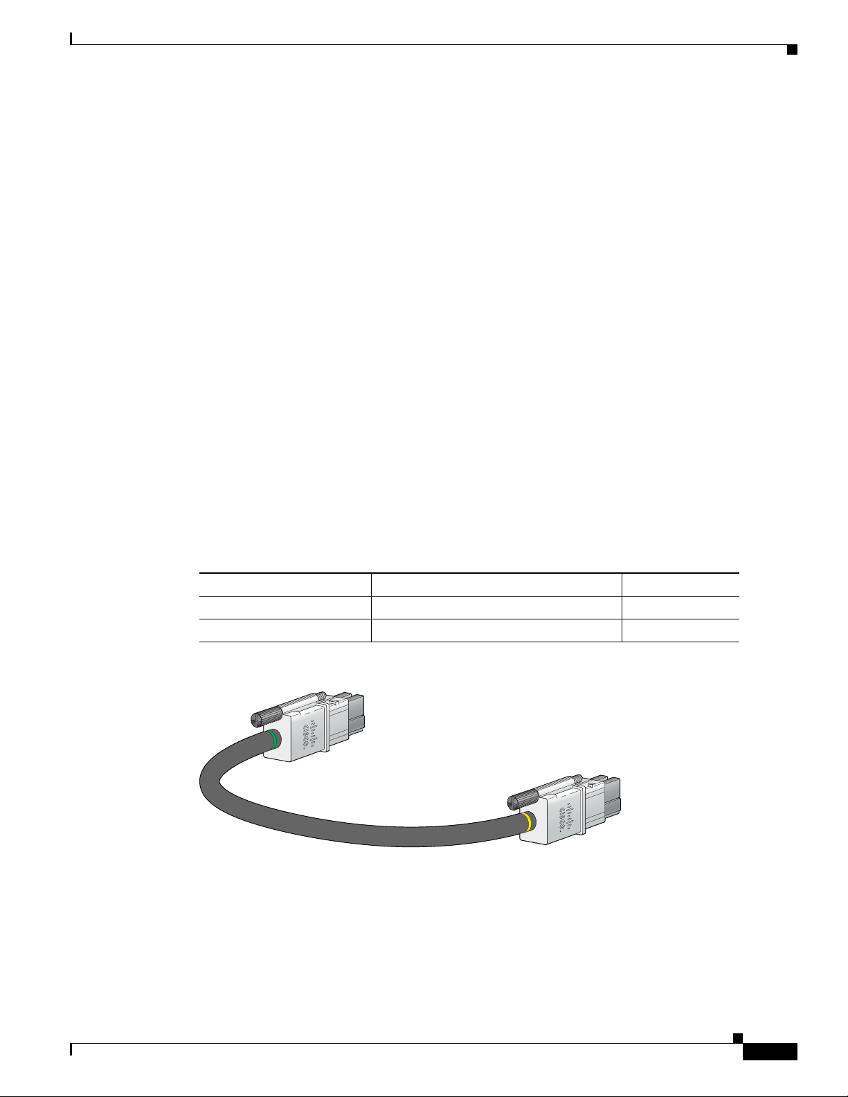
The cable in Figure 2-7 connects a Catalyst 3850 switch to another Catalyst 3850 switch in a power stack
or with an XPS. StackPower cables have color bands on the cable ends:
StackPower Cabling Configurations
• The cable end with the green band can connect only to a Catalyst 3850 switch.
• The cable end with the yellow band can connect to a Catalyst 3850 switch or an XPS.
The cable is available in two lengths.
Table 2-1 StackPower Cables
Part Number Cable Type Length
CAB-SPWR-30CM StackPower cable 0.3 meter
CAB-SPWR-150CM StackPower cable 1.5 meter
Figure 2-7 StackPower Cable for Use with Catalyst 3850 Switches
OL-26779-02
Catalyst 3850 Switch Hardware Installation Guide
2-9
Page 44

StackPower Cabling Configurations
AC OK
C3
PS OK
AC OK
C3
PS OK
Figure 2-8 shows a ring configuration using both of the supplied 0.3-meter StackPower cables and one
1.5-meter cable. In these examples, the switches are stacked in a vertical rack or on a table.
Figure 2-8 StackPower Ring Topology
RESET
CONSOLE
RESET
CONSOLE
RESET
CONSOLE
RESET
CONSOLE
Chapter 2 Switch Installation
PWR-C1-715WAC
PS OK
AC OK
PWR-C1-715WAC
PS OK
S-PWR 1
XPS
S-PWR 2
S-PWR 1
MGMT
MGMT
MGMT
MGMT
XPS
S-PWR 2
S-PWR 1
XPS
S-PWR 2
S-PWR 1
XPS
S-PWR 2
AC OK
C3KX-PWR-715WAC
PS OK
AC OK
C3KX-PWR-715WAC
PS OK
AC OK
C3KX-PWR-715WAC
PS OK
AC OK
C3KX-PWR-715WAC
PS OK
AC OK
C3KX-PWR-715WAC
PS OK
AC OK
C3KX-PWR-715WAC
PS OK
AC OK
334331
2-10
Catalyst 3850 Switch Hardware Installation Guide
OL-26779-02
Page 45
Chapter 2 Switch Installation
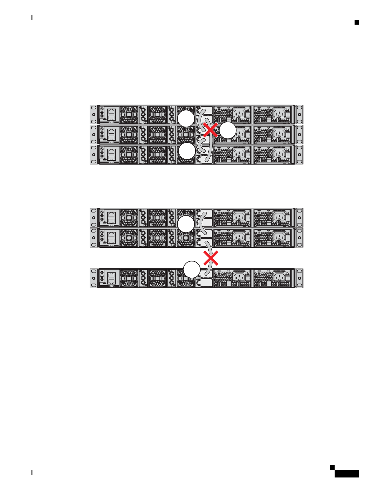
StackPower Partitioning Examples
Figure 2-9 and Figure 2-10 show StackPower stacks of Catalyst 3850 switches with failover conditions.
In Figure 2-9, the StackPower cable 2 is faulty. Therefore, this stack does not provide redundancy.
Figure 2-9 Example of a StackPower Stack with a Failover Condition
In Figure 2-10, StackPower port B on the center switch has failed and this stack partitions into two
stacks. The top two switches share power, and the bottom switch is now a separate stack.
Installing the Switch
1
2
3
344188
Figure 2-10 Example of a Partitioned StackPower Stack with a Failover Condition
Installing the Switch
• Rack-Mounting, page 2-12
• Table- or Shelf-Mounting, page 2-16
• After Installing the Switch, page 2-16
The illustrations shown in this section show the Catalyst 3850-48 PoE+ switch as an example. You can
install other Catalyst 3850 switches following the same procedures.
1
2
344189
OL-26779-02
Catalyst 3850 Switch Hardware Installation Guide
2-11
Page 46

Installing the Switch
Rack-Mounting
To install the switch in a 19-inch rack, follow the instructions described in this section.
Chapter 2 Switch Installation
Warning
To prevent bodily injury when mounting or servicing this unit in a rack, you must take special
precautions to ensure that the system remains stable. The following guidelines are provided to
ensure your safety:
• This unit should be mounted at the bottom of the rack if it is the only unit in the rack.
• When mounting this unit in a partially filled rack, load the rack from the bottom to the top with the heaviest
component at the bottom of the rack.
• If the rack is provided with stabilizing devices, install the stabilizers before mounting or servicing the unit in
the rack.
Statement 1006
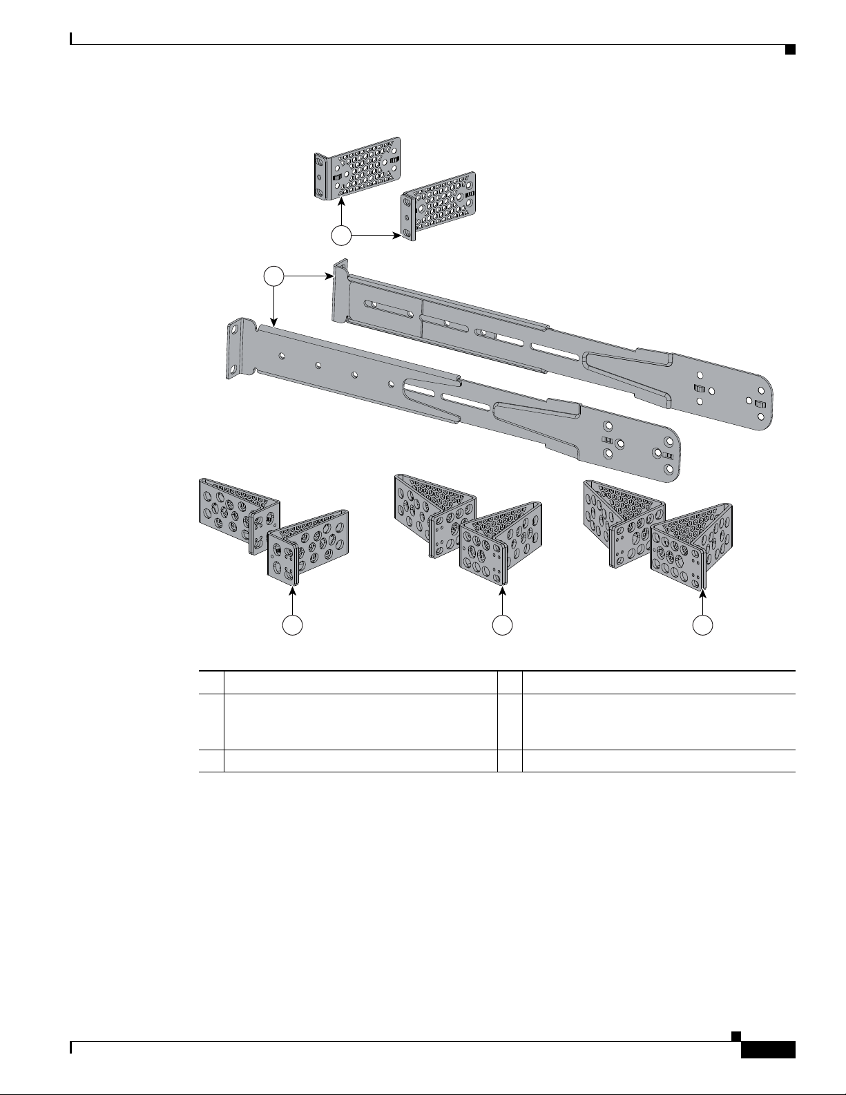
The 19-inch brackets are included with the switch. Installing the switch in other rack types requires an
optional bracket kit not included with the switch. Figure 2-11 shows the mounting brackets and part
numbers.
2-12
Catalyst 3850 Switch Hardware Installation Guide
OL-26779-02
Page 47
Chapter 2 Switch Installation
2
1
333901
3 4 5
Figure 2-11 Rack-Mounting Brackets
Installing the Switch
2 Extension rails and brackets for four-point
mounting, includes 19-inch brackets.
1 19-inch brackets (C3850-RACK-KIT=) 4 23-inch brackets (C3850-RACK-KIT=)
(C3850-4PT-KIT=)
3 ETSI brackets (C3850-RACK-KIT=)
Attaching the Rack-Mount Brackets
To install the switch in a rack, use four Phillips flat-head screws to attach the long side of the brackets
to the switch for the front- or rear-mounting positions (Figure 2-12). Use four screws to attach the
brackets for the front-mounting position.
OL-26779-02
5 24-inch brackets (C3850-RACK-KIT=)
Catalyst 3850 Switch Hardware Installation Guide
2-13
Page 48

Installing the Switch
Chapter 2 Switch Installation
Figure 2-12 Attaching Brackets for 19-inch Racks
1
2
2
3
2
2
3
2
2
2
2
333815
2-14
1 Rear-mounting position
2 Number-8 Phillips flat-head screws
3 Front-mounting position
Catalyst 3850 Switch Hardware Installation Guide
OL-26779-02
Page 49

Chapter 2 Switch Installation
4
2
1
3
333816
ACTV
Mounting the Switch in a Rack
After the brackets are attached to the switch, use the supplied Phillips machine screws to attach the
brackets to the rack (Figure 2-14). Use the black Phillips machine screw to attach the cable guide to the
left or right bracket.
When you complete the switch installation, see the “After Installing the Switch” section on page 2-16
for more information switch configuration.
Figure 2-13 Mounting the Switch in a Rack
Installing the Switch
1 Phillips machine screw, black 3 Front-mounting position
2 Cable guide 4 Number-12 or number-10 Phillips machine
screws
Catalyst 3850 Switch Hardware Installation Guide
OL-26779-02
2-15
Page 50

Installing the Switch
1
1
PWR-C1-715WAC
PWR-C1-715WAC
PWR-C1-715WAC
CONSOLE
MGMT
Table- or Shelf-Mounting
To install the switch on a table or shelf, locate the adhesive strip with the rubber feet in the mounting-kit
envelope. Attach the four rubber feet to the recessed areas on the bottom of the chassis (see Figure 2-14).
Figure 2-14 Attaching the Adhesive Pads for Table- or Shelf-Mounting
Chapter 2 Switch Installation
1 Adhesive pads
When you complete the switch installation, see the “After Installing the Switch” section on page 2-16
for more information switch configuration.
After Installing the Switch
After the switch is installed, you might need to:
• Configure the switch by running Express Setup to enter the initial switch configuration. For
instructions, see the switch getting started guide that shipped with the switch and also on Cisco.com.
• Use the CLI setup program to enter the initial switch configuration. See Appendix C, “Configuring
the Switch with the CLI-Based Setup Program.”
• Connect to the front-panel ports. See the “Installing a Network Module in the Switch” section on
page 3-4 and the “Connecting Devices to the Ethernet Ports” section on page 2-19.
Catalyst 3850 Switch Hardware Installation Guide
2-16
OL-26779-02
Page 51

Chapter 2 Switch Installation
CONSOLE
MGMT
RESET
344510
1
3
2
Connecting to the StackWise Ports
Before connecting the StackWise cables, review the “Planning a Switch Data Stack” section on page 2-4.
Always use a Cisco-approved StackWise cable to connect the switches.
Step 1 Remove the dust covers from the StackWise cables and StackWise ports, and store them for future use.
Step 2 Connect the cable to the StackWise port on the switch rear panel. Align the connector and connect the
StackWise cable to the StackWise port on the switch rear panel and finger-tighten the screws (clockwise
direction). Make sure the Cisco logo is on the top side of the connector as shown in Figure 2-15.
Step 3 Connect the other end of the cable to the port on the other switch and finger-tighten the screws. Avoid
overtightening the screws.
Figure 2-15 Connecting the StackWise Cable in a StackWise Port
Connecting to the StackWise Ports
1 Cisco logo 3 Connector screw
2 Connector screw
Catalyst 3850 Switch Hardware Installation Guide
OL-26779-02
2-17
Page 52

Connecting to the StackPower Ports
Caution Removing and installing the StackWise cable can shorten its useful life. Do not remove and
insert the cable more often than is absolutely necessary (installing and removing it up to 200
times is supported).
When you need to remove the StackWise cable from the connector, make sure to fully unscrew the
correct screws. When the connectors are not being used, replace the dust covers.
Connecting to the StackPower Ports
Before connecting the StackPower cables, review the “Planning a StackPower Stack” section on
page 2-8. Always use a Cisco-approved StackPower cable to connect the switches. To prevent
misconfiguration, the StackPower ports on the switch are keyed and have colored bands that match the
keying and bands on the StackPower cable connectors.
Follow these steps to connect the StackPower cable to the StackPower ports:
Step 1 Remove the dust covers from the StackPower cable connectors.
Step 2 Connect the end of the cable with a green band to either StackPower port on the first switch. Align the
connector correctly, and insert the it into a StackPower port on the switch rear panel. (Figure 2-16).
Chapter 2 Switch Installation
Step 3 Connect the end of the cable with the yellow band to another Catalyst 3850 switch (to configure
StackPower power sharing).
Step 4 Hand-tighten the captive screws to secure the StackPower cable connectors in place.
Figure 2-16 Connecting the StackPower Cable to a StackPower Port
AC OK
334330
S-PWR
XPS
S-PWR
AC OK
PS OK
PWR-C1-715WAC
Caution Removing and installing the StackPower cable can shorten its useful life. Do not remove and
insert the cable more often than necessary.
2-18
Catalyst 3850 Switch Hardware Installation Guide
OL-26779-02
Page 53

Chapter 2 Switch Installation
Installing a Network Module in the Switch
Installing a Network Module in the Switch
See these sections for information on network modules:
• Installing a Network Module in the Switch, page 3-4
• All ports in this module default to 10G and should be configured as TenGigabitEthernet1/1/1
through TenGigabitEthernet1/1/4, even when you are operating them as 1G using SFPs. There are
only four interfaces which are valid and the other four should not be used even though they still show
up in the CLI., page 3-7
Installing and Removing SFP and SFP+ Modules
See these sections for information on SFPs and SFP+:
• Installing SFP and SFP+ Modules, page 3-9
• Removing SFP or SFP+ Modules, page 3-11
Connecting Devices to the Ethernet Ports
• 10/100/1000 Ethernet Port Connections, page 2-19
• PoE+ and Cisco UPOE Port Connections, page 2-20
Caution Category 5e and Category 6 cables can store high levels of static electricity. Always ground the cables
to a suitable and safe earth ground before connecting them to the switch or other devices.
10/100/1000 Ethernet Port Connections
The 10/100/1000 Ethernet ports use RJ-45 connectors with Ethernet pinouts. The maximum cable length
is 328 feet (100 meters). The 100BASE-TX and 1000BASE-T traffic requires Category 5, Category 5e,
or Category 6 UTP cable. The 10BASE-T traffic can use Category 3 or Category 4 cable.
The autonegotiation feature is enabled by default on the switch. At this setting, the switch ports
configure themselves to operate at the speed of attached device. If the attached device does not support
autonegotiation, you can explicitly set the switch port speed and duplex parameters. To maximize
performance, either let the ports autonegotiate both speed and duplex, or set the port speed and duplex
parameters on both ends of the connection.
For simplified cabling, the automatic medium-dependent interface crossover (auto-MDIX) feature is
enabled by default on the switch. With auto-MDIX enabled, the switch detects the required cable type
for copper Ethernet connections and configures the interface accordingly. Therefore, you can use either
a crossover or a straight-through cable for connections to a switch 10/100/1000 Ethernet port regardless
of the type of device on the other end of the connection.
See the switch software configuration guide or the switch command reference on Cisco.com for more
information about enabling or disabling autonegotiation and auto-MDIX.
OL-26779-02
If auto-MDIX is disabled, use the guidelines in Tab l e 2-2 to select the correct cable for connecting the
switch 10/100/1000 Ethernet ports to other devices. See the “Cable and Adapter Specifications” section
on page B-5 for cable-pinout descriptions.
Catalyst 3850 Switch Hardware Installation Guide
2-19
Page 54

Connecting Devices to the Ethernet Ports
Table 2-2 Recommended Ethernet Cables (When Auto-MDIX is Disabled)
Chapter 2 Switch Installation
Device Crossover Cable
Switch to switch Yes No
Switch to hub Yes No
Switch to computer or server No Yes
Switch to router No Yes
Switch to IP phone No Yes
1. 100BASE-TX and 1000BASE-T traffic requires twisted four-pair, Category 5, Category 5e, or
Category 6 cable. 10BASE-T traffic can use Category 3 or Category 4 cable.
PoE+ and Cisco UPOE Port Connections
The 10/100/1000 PoE+ and Cisco UPOE ports have the same autonegotiation settings and cabling
requirements that are described in the “10/100/1000 Ethernet Port Connections” section on page 2-19.
These ports can provide PoE, PoE+, or Cisco UPOE inline power.
PoE inline power supports devices compliant with the IEEE 802.3af standard, as well as prestandard
Cisco IP Phones and Cisco Aironet Access Points. Each port can deliver up to 15.4 W of PoE.
PoE+ inline power supports devices compliant with the IEEE 802.3at standard, by delivering up to 30 W
of PoE+ power per port to all switch ports.
See Table 1-15 on page 1-19 for the power supply modules required to support PoE, PoE+, and Cisco
UPOE on 24- and 48-port switches.
1
Straight-Through Cable
1
For more information about the required power-supply module and the PoE specifications, see the
“Power Supply Modules” section on page 1-18 and Appendix A, “Technical Specifications.”
Note Many legacy powered devices, including older Cisco IP phones and access points that do not fully
support IEEE 802.3af, might not support PoE when connected to the switches by a crossover cable.
Caution PoE faults are caused when noncompliant cabling or powered devices are connected to a PoE port. Use
only standard-compliant cabling to connect Cisco prestandard IP Phones, wireless access points, or
IEEE 802.3af-compliant devices to PoE ports. A cable or device that causes a PoE fault must be removed
from the network.
Warning
Voice over IP (VoIP) service and the emergency calling service do not function if power fails or is
disrupted. After power is restored, you might have to reset or reconfigure equipment to regain access
to VoIP and the emergency calling service. In the USA, this emergency number is 911. You need to be
aware of the emergency number in your country.
Statement 361
2-20
Catalyst 3850 Switch Hardware Installation Guide
OL-26779-02
Page 55

Chapter 2 Switch Installation
Where to Go Next
Warning
Voltages that present a shock hazard may exist on Power over Ethernet (PoE) circuits if
interconnections are made using uninsulated exposed metal contacts, conductors, or terminals.
Avoid using such interconnection methods, unless the exposed metal parts are located within a
restricted access location and users and service people who are authorized within the restricted
access location are made aware of the hazard. A restricted access area can be accessed only through
the use of a special tool, lock and key or other means of security.
Where to Go Next
If the default configuration is satisfactory, the switch does not need further configuration. You can use
any of these management options to change the default configuration:
• Start the Network Assistant application, which is described in the Getting Started with Cisco
Network Assistant guide. Through this GUI, you can configure and monitor a switch cluster or an
individual switch.
• Use the CLI to configure the switch as a member of a cluster or as an individual switch from the
console. See the switch command reference on Cisco.com for information on using the CLI with the
switch.
• Use the Cisco Prime Infrastructure application.
Statement 1072
OL-26779-02
Catalyst 3850 Switch Hardware Installation Guide
2-21
Page 56

Where to Go Next
Chapter 2 Switch Installation
2-22
Catalyst 3850 Switch Hardware Installation Guide
OL-26779-02
Page 57

Overview
CHAP T E R
Installing a Network Module
This chapter describes how to install and connect a network module.
• Overview, page 3-1
• Installing a Network Module in the Switch, page 3-4
• Configuring a Network Module, page 3-7
• Removing a Network Module, page 3-9
• SFP and SFP+ Modules, page 3-9
• Finding the Network Module Serial Number, page 3-11
Table 3-1 Network Modules
3
Network Module
C3850-NM-4-1G This module has four 1-Gigabit SFP module slots. Any combination of
C3850-NM-2-10G This module has four slots that support the following combinations:
1
Description
standard SFP modules are supported. SFP+ modules are not supported.
If you insert an SFP+ module in the 1-Gigabit network module, the SFP+
module does not operate, and the switch logs an error message.
• Two slots (left side) support only 1-Gigabit SFP modules and two
slots (right side) support either 1-Gigabit SFP or 10-Gigabit SFP
modules.
• Three slots (left side) support 1-Gigabit SFP modules and one slot
(right side) supports 10-Gigabit Ethernet SFP+.
Supported combinations of SFP and SFP+ modules:
• Slots 1, 2, 3, and 4 populated with 1-Gigabit SFP modules.
• Slots 1 and 2 populated with 1-Gigabit SFP modules, and Slot 4
populated with one 10-Gigabit SFP+ module.
• Slots 3 and 4 each populated with 10-Gigabit SFP+ modules.
OL-26779-02
Catalyst 3850 Switch Hardware Installation Guide
3-1
Page 58
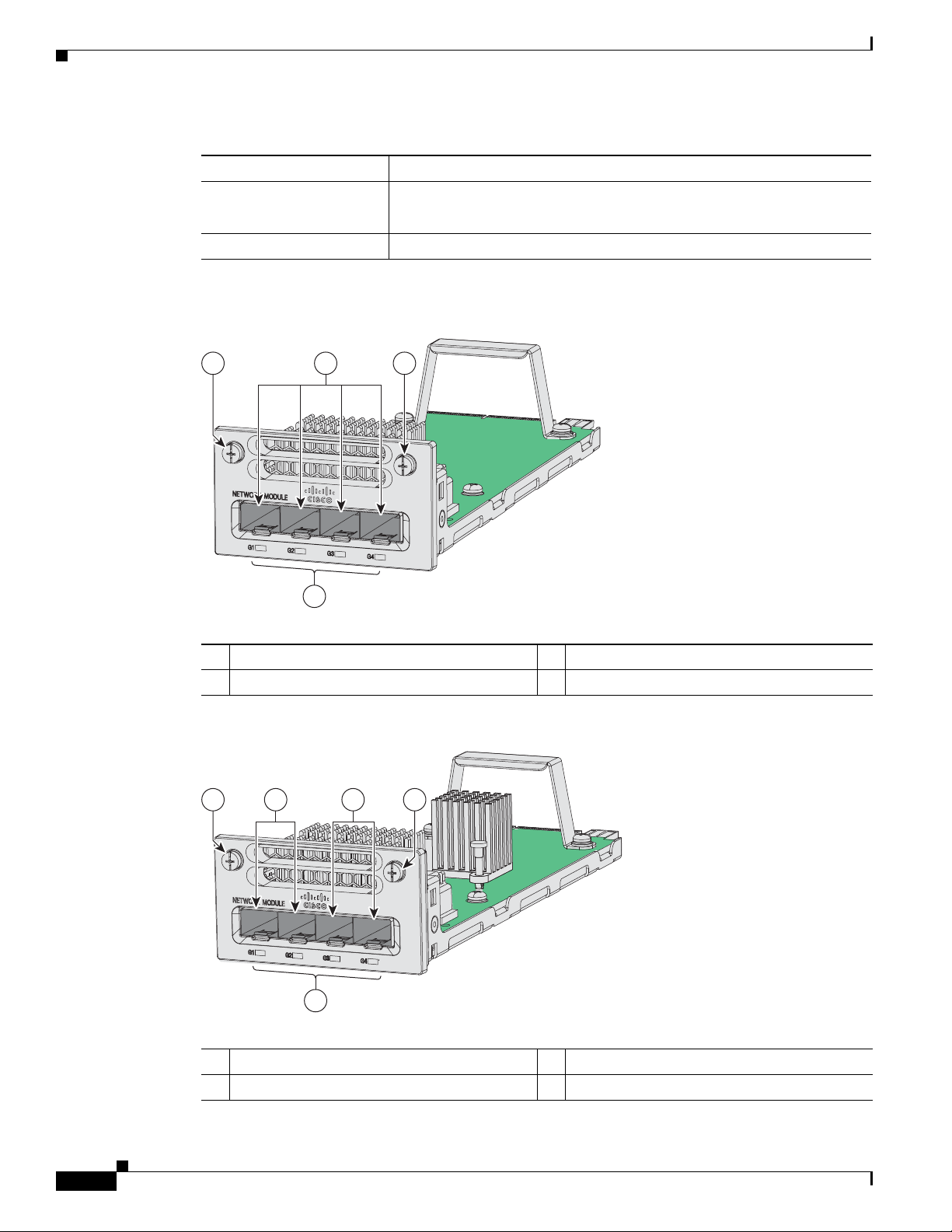
Overview
C3850-NM-4-1G
3
1 1
344197
2
C3850-NM-2-10G
TE3
TE4
344196
11 23
4
Chapter 3 Installing a Network Module
Table 3-1 Network Modules (continued)
Network Module
1
Description
C3850-NM-4-10G This module has four 10-Gigabit slots or four 1-Gigabit slots.
Note This is only supported on the 48-port models.
C3850-NM-BLANK This module has no uplink ports.
1. All network modules are hot-swappable.
Figure 3-1 C3850-NM-4-1G Network Module
1 Captive screws 3 LEDs
2 1-Gigabit Ethernet ports
Figure 3-2 C3850-NM-2-10G Network Module
1 Captive screws 3 1-Gigabit Ethernet SFP slots
2 1-Gigabit or 10-Gigabit Ethernet SFP+ slots 4 LEDs
3-2
Catalyst 3850 Switch Hardware Installation Guide
OL-26779-02
Page 59
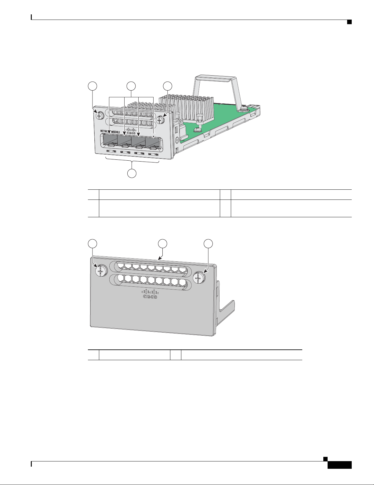
Chapter 3 Installing a Network Module
11 2
3
344195
C3850-NM-4-10G
Figure 3-3 C3850-NM-4-10G Network Module
Overview
1 Captive screws 3 LEDs
2 10-Gigabit slots or 1-Gigabit Ethernet SFP
slots
Figure 3-4 Blank Network Module
1 22
C3850-NM-BLANK
344198
1 Blank module 2 Captive screws
OL-26779-02
Catalyst 3850 Switch Hardware Installation Guide
3-3
Page 60
Installing a Network Module in the Switch
Network Module LEDs
The network module LEDs show the link status for the transceivers.
Table 3-2 Network Module LEDs
Color Link Status
Off Link is off.
Green Link is on, no activity.
Blinking green Activity on a link, no faults.
Blinking amber Link is off due to a fault or because it has exceeded a limit set in the switch
Chapter 3 Installing a Network Module
software.
Caution Link faults are caused when noncompliant cabling is connected
to an SFP or an SFP+ port. Use only standard-compliant
cabling to connect to SFP and SFP+ ports. You must remove
from the network any cable or device that causes a link fault.
Amber Link for the SFP or SFP+ is disabled.
Installing a Network Module in the Switch
• Safety Warnings, page 3-4
• Tools and Equipment, page 3-5
• Installing Network Modules, page 3-5
Safety Warnings
This section includes the installation cautions and warnings. Translations of the safety warnings appear
in the Regulatory Compliance and Safety Information for the Catalyst 3850 Switches on Cisco.com:
http://www.cisco.com/go/cat3850_hw
Read this section before you install a network module.
Caution Proper ESD protection is required whenever you handle equipment. Installation and maintenance
personnel should be properly grounded by grounding straps to eliminate the risk of ESD damage to the
equipment. Equipment is subject to ESD damage whenever you remove it.
3-4
Warning
Catalyst 3850 Switch Hardware Installation Guide
Only trained and qualified personnel should be allowed to install, replace, or service this equipment.
Statement 1030
OL-26779-02
Page 61

Chapter 3 Installing a Network Module
Installing a Network Module in the Switch
Warning
Do not reach into a vacant slot or chassis while you install or remove a module. Exposed circuitry
could constitute an energy hazard.
Tools and Equipment
You need to supply a number-2 Phillips screwdriver.
Installing Network Modules
Note Although network modules are hot-swappable, we recommend installing a network module before
powering the switch.
Note The switch can operate without a network module, but a blank module (with no ports or SFP slots) is
available and should be installed when uplink ports are not required.
Note The switch generates logs when you insert or remove a network module with SFP slots.
Statement 206
Use only supported network modules and SFP or SFP+ modules. Each module has an internal serial
EEPROM that is encoded with security information. For information about supported SFP modules, see
the “SFP and SFP+ Modules” section on page 1-8.
The network module is hot-swappable. If you remove a module, replace it with another network module
or a blank module.
Note The switch complies with EMC, safety, and thermal specifications when a network module is present.
If no uplink ports are required, install a blank network module.
When installing network modules, observe these precautions:
• Do not remove the EMC plug from the 10-Gigabit Ethernet slot until you install an SFP or SFP+
module. Either a module or a dust plug must be in the slot at all times.
• Do not remove the dust plugs from the fiber-optic SFP modules or the rubber caps from the
fiber-optic cable until you connect the cable. The plugs and caps protect the module ports and cables
from contamination and ambient light.
• Removing and installing a network module can shorten its useful life. Do not remove and insert a
network module more often than is necessary.
• To prevent ESD damage, follow your normal board and component handling procedures when
connecting cables to the switch and other devices.
Step 1 Attach an ESD-preventive wrist strap to your wrist and to an earth ground surface.
OL-26779-02
Step 2 Remove the module from the protective packaging.
Catalyst 3850 Switch Hardware Installation Guide
3-5
Page 62
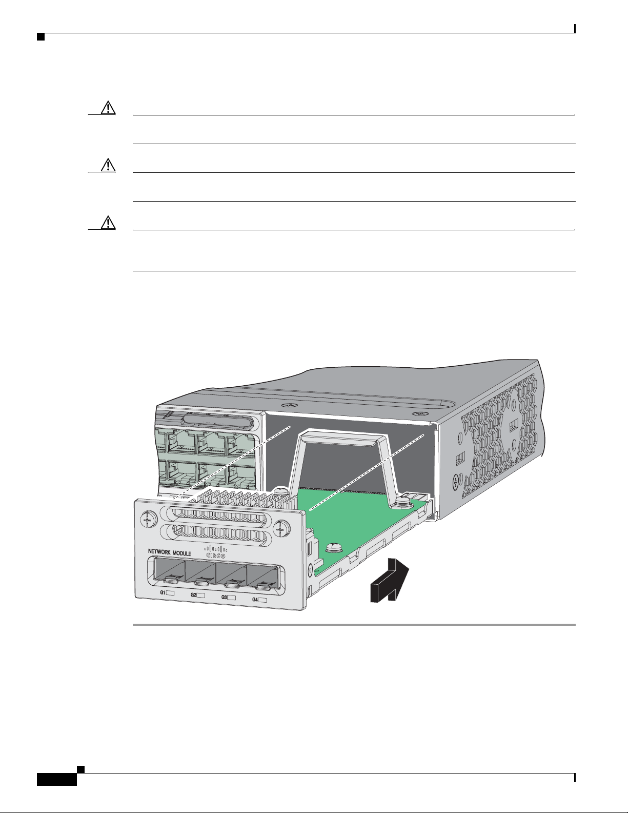
Installing a Network Module in the Switch
344199
C3850-NM-4-1G
Catalyst 3850 48 PoE+
Step 3 Remove the 10-Gigabit Ethernet module slot EMC plug, and save it.
Caution Verify the correct orientation of your module before installing it. Incorrect installation can damage the
module.
Caution Do not install the network module with connected cables or installed SFP modules. Always remove any
cables and modules before you install the network module.
Caution A module interface might become error-disabled when a network module with connected fiber-optic
cables is installed or removed. If an interface is error-disabled, you can reenable the interface by using
the shutdown and no shutdown interface configuration commands.
Step 4 Position the module face up to install it in the module slot. Slide the module into the slot until the back
of the module faceplate is flush with the switch faceplate. Fasten the captive screws to secure the
network module in place.
Chapter 3 Installing a Network Module
Figure 3-5 Installing the Network Module in the Switch
3-6
Catalyst 3850 Switch Hardware Installation Guide
OL-26779-02
Page 63

Chapter 3 Installing a Network Module
Configuring a Network Module
C3850-NM-4-1G module
All ports in this module are natively GigabitEthernet and are configured GigabitEthernet1/1/1 though
GigabitEthernet1/1/4. There are only four interfaces which are valid and the other four should not be
used even though they still show up in the CLI.
Interface Action
GigabitEthernet1/1/1 Configure this interface
GigabitEthernet1/1/2 Configure this interface
GigabitEthernet1/1/3 Configure this interface
GigabitEthernet1/1/4 Configure this interface
TenGigabitEthernet1/1/1 Disregard
TenGigabitEthernet1/1/2 Disregard
TenGigabitEthernet1/1/3 Disregard
TenGigabitEthernet1/1/4 Disregard
Configuring a Network Module
C3850-NM-4-10G module
All ports in this module default to 10G and should be configured as TenGigabitEthernet1/1/1 through
TenGigabitEthernet1/1/4, even when you are operating them as 1G using SFPs. There are only four
interfaces which are valid and the other four should not be used even though they still show up in the
CLI.
Interface Action
GigabitEthernet1/1/1 Disregard
GigabitEthernet1/1/2 Disregard
GigabitEthernet1/1/3 Disregard
GigabitEthernet1/1/4 Disregard
TenGigabitEthernet1/1/1 Configure this interface
TenGigabitEthernet1/1/2 Configure this interface
TenGigabitEthernet1/1/3 Configure this interface
TenGigabitEthernet1/1/4 Configure this interface
OL-26779-02
Catalyst 3850 Switch Hardware Installation Guide
3-7
Page 64

Configuring a Network Module
C3850-NM-2-10G module
The first two parts are natively 1G ports and the last two ports are natively 10G ports. So you configure
the 1G posts as GigabitEthernet1/1/1 through GigabitEthernet1/1/2, and configure the last two ports as
TenGigabitEthernet1/1/3 through TenGigabitEthernet1/1/4, even when you are operating the last two
ports as 1G. There are only four interfaces which are valid and the other four should not be used even
though they still show up in the CLI.
Interface Action
GigabitEthernet1/1/1 Configure this interface
GigabitEthernet1/1/2 Configure this interface
GigabitEthernet1/1/3 Disregard
GigabitEthernet1/1/4 Disregard
TenGigabitEthernet1/1/1 Disregard
TenGigabitEthernet1/1/2 Disregard
TenGigabitEthernet1/1/3 Configure this interface, even when operating as 1G
TenGigabitEthernet1/1/4 Configure this interface, even when operating as 1G
Chapter 3 Installing a Network Module
Supported GBICs
TenGigabitEthernet: GigabitEthenet
• SFP-H10GB-CU1M
• SFP-H10GB-CU3M
• SFP-H10GB-CU5M
• SFP-10G-SR
• SFP-10G-LRM
• SFP-10G-LR
• SFP-10G-ER
• GLC-T (10/100/1000)
• GLC-SX-MM
• GLC-LH-SM
• GLC-SX-MMD
• GLC-LH-SMD
• GLC-ZX-SM
• GLC-ZX-SMD
• GLC-BX-D
• GLC-BX-U
• CWDM SFP
• SFP-GE-S
• SFP-GE-L
• SFP-GE-Z
• DWDM SFP
3-8
• DWDM SFP (add.)
Catalyst 3850 Switch Hardware Installation Guide
OL-26779-02
Page 65

Chapter 3 Installing a Network Module
Removing a Network Module
Note The switch meets the applicable compliance and thermal specifications when a network module is
present. If no uplink ports are required, install a blank network module.
Step 1 Attach an ESD-preventive wrist strap to your wrist and to an earth ground surface.
Caution Do not remove the network module with installed SFP cables or modules. Always remove any cables
and modules before removing the network module from the slot.
Caution A module interface might become error-disabled when a network module with connected fiber-optic
cables is installed or removed. If an interface is error-disabled, you can reenable the interface by using
the shutdown and no shutdown interface configuration commands.
Removing a Network Module
Step 2 Disconnect the cables from the SFP modules.
Step 3 Remove the SFP modules from the network module.
Step 4 Loosen the captive screws that hold the network module in place.
Step 5 Carefully press the tab on the right side of the network module to release it. Grasp the edges of the
module, and carefully slide it out of the slot.
Step 6 Install a replacement network module or a blank module in the slot.
Step 7 Place the module that you removed in an antistatic bag or other protective environment.
SFP and SFP+ Modules
See the “SFP and SFP+ Modules” section on page 1-8 for information on the supported modules.
Installing SFP and SFP+ Modules
You must have an installed network module to use SFP and SFP+ modules.
See the “SFP and SFP+ Modules” section on page 1-8, and the switch release notes on Cisco.com for
the list of supported SFP and SFP+ modules. Use only supported SFP modules on the switch. See the
following compatibility matrices:
OL-26779-02
• 10-Gigabit Ethernet Transceiver Modules Compatibility Matrix
• Cisco Gigabit Ethernet Transceiver Modules Compatibility Matrix
For cable specifications, see Appendix B, “Connector and Cable Specifications.”
Observe these precautions:
Catalyst 3850 Switch Hardware Installation Guide
3-9
Page 66

SFP and SFP+ Modules
333418
C3850-NM-4-1G
Catalyst 3850 48 PoE+
Chapter 3 Installing a Network Module
Warning
Class 1 laser product.
Statement 1008
• Do not remove the dust plugs from the SFP modules or the rubber caps from the fiber-optic cable
until you are ready to connect the cable. The plugs and caps protect the module ports and cables
from contamination and ambient light.
• Removing and installing an SFP module can shorten its useful life. Do not remove and insert any
SFP module more often than is necessary.
• To prevent ESD damage, follow your normal board and component handling procedures when
connecting cables to the switch and other devices.
Caution To avoid damage to the network module, install the network module before you install the SFP or SFP+
modules.
Step 1 Attach an ESD-preventive wrist strap to your wrist and to an earth ground surface.
Step 2 Find the send (TX) and receive (RX) markings that identify the top of the SFP module.
On some SFP modules, the send and receive (TX and RX) markings might be shown by arrows that show
the direction of the connection.
Step 3 If the SFP module has a bale-clasp latch, move it to the open, unlocked position.
Step 4 Align the module in front of the slot opening, and push until you feel the connector snap into place.
Figure 3-6 Installing an SFP Module in the Network Module
Step 5
If the module has a bale-clasp latch, close it to lock the SFP module in place.
Step 6 Remove the SFP dust plugs and save.
Step 7 Connect the SFP cables.
3-10
Catalyst 3850 Switch Hardware Installation Guide
OL-26779-02
Page 67

Chapter 3 Installing a Network Module
Figure 3-7 Network Module with SFP Modules Installed
Catalyst 3850 48 PoE+
1 Network module 3 Send (TX) optical bore
2 SFP modules 4 Receive (RX) optical bore
Removing SFP or SFP+ Modules
Finding the Network Module Serial Number
C3850-NM-4-1G
333419
Step 1 Attach an ESD-preventive wrist strap to your wrist and to an earth ground surface.
Step 2 Disconnect the cable from the SFP module. For reattachment, note which cable connector plug is send
(TX) and which is receive (RX).
Step 3 Insert a dust plug into the optical ports of the SFP module to keep the optical interfaces clean.
Step 4 If the module has a bale-clasp latch, pull the bale out and down to eject the module. If you cannot use
your finger to open the latch, use a small, flat-blade screwdriver or other long, narrow instrument to open
it.
Step 5 Grasp the SFP module, and carefully remove it from the slot.
Step 6 Place the SFP module in an antistatic bag or other protective environment.
Finding the Network Module Serial Number
If you contact Cisco Technical Assistance regarding a network module, you need to know its serial
number.
OL-26779-02
Catalyst 3850 Switch Hardware Installation Guide
3-11
Page 68

Finding the Network Module Serial Number
SN: XXXNNNNXXXX
334336, 781-00762-01
C3850-NM-2-10G
Figure 3-8 Network Module Serial Number Location
Chapter 3 Installing a Network Module
3-12
Catalyst 3850 Switch Hardware Installation Guide
OL-26779-02
Page 69

Power Supply Installation
This chapter describes how to install the power supply modules.
• Power Supply Module Overview, page 4-1
• Installation Guidelines, page 4-5
• Installing or Replacing an AC Power Supply, page 4-6
• Installing a DC Power Supply, page 4-7
• Finding the Power Supply Module Serial Number, page 4-12
Power Supply Module Overview
The switch operates with either one or two active power supply modules. A Catalyst 3850 switch that is
part of a StackPower stack operates with power supplied by other stack switches.
You can use two AC modules, two DC modules, one AC and one DC module, or one module and a blank
cover.
All power supply modules have internal fans. All switches ship with a blank cover in the second power
supply slot.
CHAP T E R
4
OL-26779-02
Table 4-1 describes the supported internal power supply modules.
Table 4-1 Power Supply Module Part Numbers and Descriptions
Part Number Description
PWR-C1-1100WAC= 1100-W AC power supply module
PWR-C1-715WAC= 715-W AC power supply module
PWR-C1-350WAC= 350-W AC power supply module
CPWR-C1-440WDC= 440-W DC power supply module
PWR-C1-BLANK Blank cover
For information on available PoE, see these sections:
• Table 1-13 on page 1-19 (available PoE with AC power supply)
• Table 1-14 on page 1-19 (available PoE with DC power supply)
• Table 1-15 on page 1-19 (switch power supply requirements for PoE and PoE+, and Cisco UPOE)
Catalyst 3850 Switch Hardware Installation Guide
4-1
Page 70

Power Supply Module Overview
Note A 48-port switch with one 715-W power supply provides up to 7.7 W of PoE to all ports.
The 350-W and 715-W AC power supply modules are autoranging units that support input voltages
between 100 and 240 VAC. The 1100-W power supply module is an autoranging unit that supports input
voltages between 115 and 240 VAC. The 440-W DC power supply module has dual input feeds (A and
B) and supports input voltages between 36 and 72 VDC. The output voltage range is 51 to 57 V.
Each AC power supply module has a power cord for connection to an AC power outlet. The 1100-W and
715-W modules use a 16-AWG cord (only North America). All other modules use an 18-AWG cord. The
DC power supply module must be wired to a DC power source.
Figure 4-1 to Figure 4-4 show the power supply modules.
Figure 4-1 1100-W AC Power Supply
Chapter 4 Power Supply Installation
1
2
3
4
AC OK
PS OK
PWR-C1-1100WAC
6
5
1 1100-W AC power supply module 5 Release latch
2 AC OK LED 6 Power cord retainer
3 PS OK LED 7 Keying feature
4 AC power cord connector
7
334375
4-2
Catalyst 3850 Switch Hardware Installation Guide
OL-26779-02
Page 71

Chapter 4 Power Supply Installation
Figure 4-2 715-W AC Power Supply Module
Power Supply Module Overview
1
2
3
4
AC OK
PS OK
PWR-C1-715WAC
6
5
7
1 715-W AC power supply module 5 Release latch
2 AC OK LED 6 Power cord retainer
3 PS OK LED 7 Keying feature
4 AC power cord connector
Figure 4-3 350-W AC Power Supply Module
1
2
3
4
7
334376
AC OK
PS OK
PWR-C1-350WAC
334377
6
5
1 350-W AC power supply module 5 Release latch
2 AC OK LED 6 Power cord retainer
3 PS OK LED 7 Keying feature
4 AC power cord connector
OL-26779-02
Catalyst 3850 Switch Hardware Installation Guide
4-3
Page 72

Power Supply Module Overview
DC OK
PWR-C1-440WDC
PS OK
334378
1
8
2
3
7
4
5 6 5 4
INPUT
-36 TO -72V
/12A
OUTPUT
44W MAX
/22A
9
10
Figure 4-4 440-W DC Power Supply Module
1 440-W DC power supply module 6 Grounding terminal
2 DC OK LED 7 Release latch
3 PS OK LED 8 Extraction handle
4 Input power terminals (positive polarity) 9 Terminal block safety cover
5 Input power terminals (negative polarity) 10 Keying feature
Chapter 4 Power Supply Installation
If no power supply is installed in a power supply slot, install a power supply slot cover (Figure 4-5).
Figure 4-5 Power Supply Slot Cover
2
1
253564
1 Release handles 2 Retainer clips
The power supply modules have two status LEDs.
4-4
Catalyst 3850 Switch Hardware Installation Guide
OL-26779-02
Page 73

Chapter 4 Power Supply Installation
Table 4-2 Switch Power Supply Module LEDs
AC Power Supply Module LEDs
AC OK Description PS OK Description
Off
(AC LED is
off)
Green AC input power present. Green Power output to switch.
DC Power Supply Module LEDs
DC OK Description PS OK Description
Off
(DC LED is
off)
Green DC input power present. Green Power output to switch.
Installation Guidelines
No AC input power. Off Output is disabled, or input is
outside operating range.
Red Output has failed.
No DC input power. Off Output is disabled, or input is
outside operating range.
Red Output has failed.
Installation Guidelines
Table 4-1 lists the switches and the compatible power-supply modules. Observe these guidelines when
removing or installing a power supply or fan module:
• Do not force the power supply or fan module into the slot. This can damage the pins on the switch
if they are not aligned with the module.
• A power supply that is only partially connected to the switch can disrupt the system operation.
• Remove power from the power-supply module before removing or installing the module.
• The power supply is hot-swappable. In some configurations, such as full PoE+ or power sharing
mode, removing a power supply causes powered devices to shut down until the power budget
matches the input power of a single power supply. To minimize network interruption, hot swap the
power supply under these circumstances:
–
The switch is in StackPower mode and sufficient power is available.
–
The switch is powered by other switches in a power stack, and no active backup is in progress.
For the switch commands that display available power budget, see the software configuration guide.
Caution Do not operate the switch with one power-supply module slot empty. For proper chassis cooling, both
module slots must be populated, with either a power supply or a blank module.
OL-26779-02
Warning
Blank faceplates and cover panels serve three important functions: they prevent exposure to
hazardous voltages and currents inside the chassis; they contain electromagnetic interference (EMI)
that might disrupt other equipment; and they direct the flow of cooling air through the chassis. Do not
operate the system unless all cards, faceplates, front covers, and rear covers are in place.
Statement 1029
Catalyst 3850 Switch Hardware Installation Guide
4-5
Page 74

Installing or Replacing an AC Power Supply
Chapter 4 Power Supply Installation
Warning
Warning
Warning
Do not reach into a vacant slot or chassis while you install or remove a module. Exposed circuitry
could constitute an energy hazard.
Only trained and qualified personnel should be allowed to install, replace, or service this equipment.
Statement 1030
If a Cisco external power system is not connected to the switch, install the provided connector cover
on the back of the switch.
Statement 386
Statement 206
Installing or Replacing an AC Power Supply
Step 1 Turn off the power at its source.
Step 2 Remove the power cord from the power cord retainer.
Step 3 Remove the power cord from the power connector.
Step 4 Press the release latch at the right side of the power supply module inward and slide the power supply
out. (Figure 4-6).
Caution Do not leave the power-supply slot open for more than 90 seconds while the switch is operating.
Warning
Step 5 Insert the new power supply into the power-supply slot, and gently push it into the slot (Figure 4-6).
This unit might have more than one power supply connection. All connections must be removed to
de-energize the unit.
Statement 1028
When correctly inserted, the 350-W and 715-W power supplies (excluding the power cord retainer) are
flush with the switch rear panel. The 1100-W power-supply module extends 1.5 inches from the switch
rear panel.
4-6
Catalyst 3850 Switch Hardware Installation Guide
OL-26779-02
Page 75
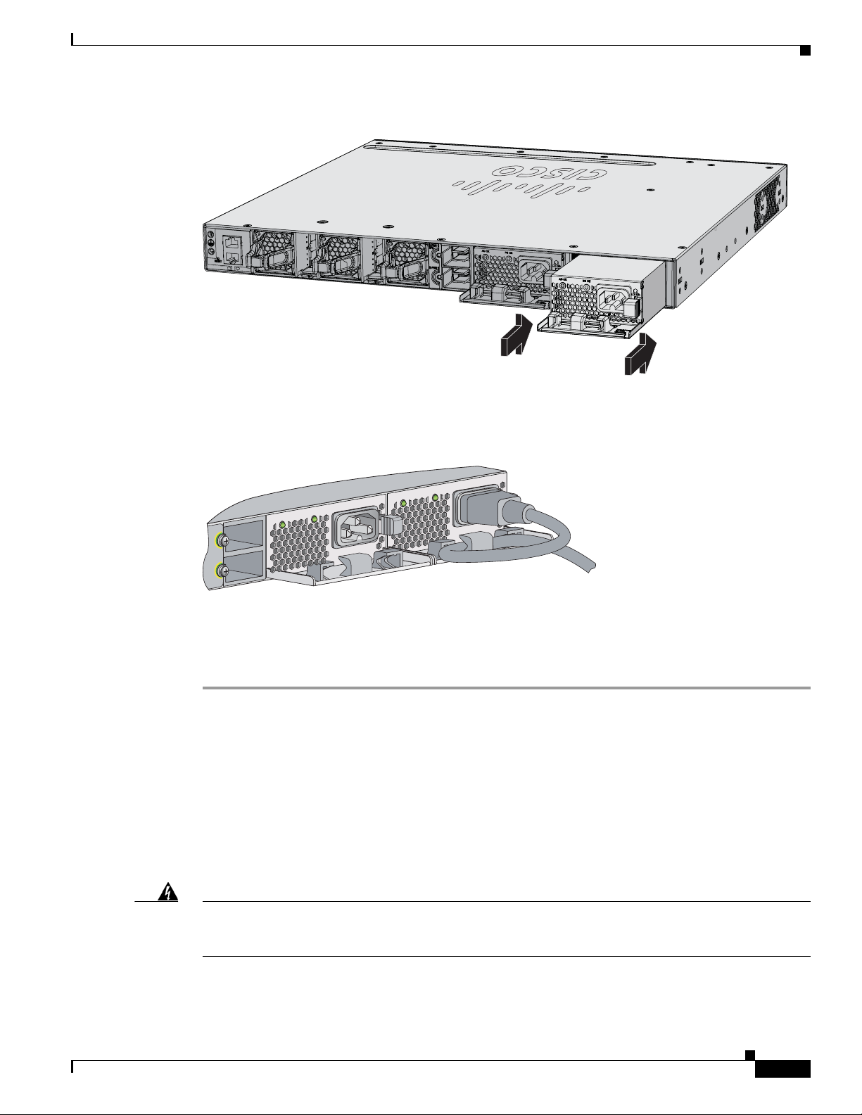
Chapter 4 Power Supply Installation
PWR-C1-715WAC
PWR-C1-715WAC
344192
CONSOLE
MGMT
Figure 4-6 Inserting the AC-Power Supply in the Switch
Installing a DC Power Supply
Step 6
(Optional) Make a loop in the power cord and thread it through the power cord retainer (Figure 4-7).
Figure 4-7 AC-Power Supply with Power Cord Retainer
AC OK
Step 7
PWR-C1-715WAC
PS OK
AC OK
Connect the power cord to the power supply and to an AC power outlet. Turn on the power at the power
source.
Step 8 Confirm that the power supply AC OK and PS OK LEDs are green. See Tabl e 1- 16 for a description of
the power supply module LEDs.
Installing a DC Power Supply
• Equipment That You Need, page 4-8
• Grounding the Switch, page 4-8
• Installing the DC Power Supply in the Switch, page 4-11
PS OK
PWR-C1-715WAC
334332
• Wiring the DC Input Power Source, page 4-11
Warning
An exposed wire lead from a DC-input power source can conduct harmful levels of electricity. Be sure
that no exposed portion of the DC-input power source wire extends from the terminal block plug.
Statement 122
Catalyst 3850 Switch Hardware Installation Guide
OL-26779-02
4-7
Page 76

Installing a DC Power Supply
Chapter 4 Power Supply Installation
Warning
Warning
Warning
Warning
Note The grounding architecture of this product is DC-isolated (DC-I).
Before performing any of the following procedures, ensure that power is removed from the DC circuit.
Statement 1003
This product relies on the building’s installation for short-circuit (overcurrent) protection. Ensure that
the protective device is rated not greater than: 20 A.
A readily accessible two-poled disconnect device must be incorporated in the fixed wiring.
Statement 1022
Hazardous voltage or energy may be present on power terminals. Always replace cover when
terminals are not in service. Be sure uninsulated conductors are not accessible when cover is in
place.
Statement 1086
Equipment That You Need
Statement 1005
• Ratcheting torque screwdriver with a number-2 Phillips head that exerts up to 15 pound-force inches
(lbf-in.) of pressure.
• Panduit crimping tool with optional controlled-cycle mechanism (model CT-720, CT-920,
CT-920CH, CT-930, or CT-940CH).
• Wire-stripping tools.
• 12-gauge copper ground wire (insulated or not) for the single-ground connection.
• 8-gauge copper ground wire (insulated or not) for the dual-ground connection.
• Ground lug screw (not included in the accessory kit) and ring lug connector in the switch accessory
kit. For a dual-ground connection, also use the dual-ground adapter and dual lug connector.
• Four leads of 14-gauge copper wire.
• Four fork-type terminals from the DC power supply accessory kit. The terminals must be the proper
size for M3 screws in a Dinkle DT-35-B25-style terminal block.
Grounding the Switch
Follow the grounding procedures at your site and observe these warnings:
Warning
This equipment must be grounded. Never defeat the ground conductor or operate the equipment in the
absence of a suitably installed ground conductor. Contact the appropriate electrical inspection
authority or an electrician if you are uncertain that suitable grounding is available.
Statement 1024
4-8
Catalyst 3850 Switch Hardware Installation Guide
OL-26779-02
Page 77
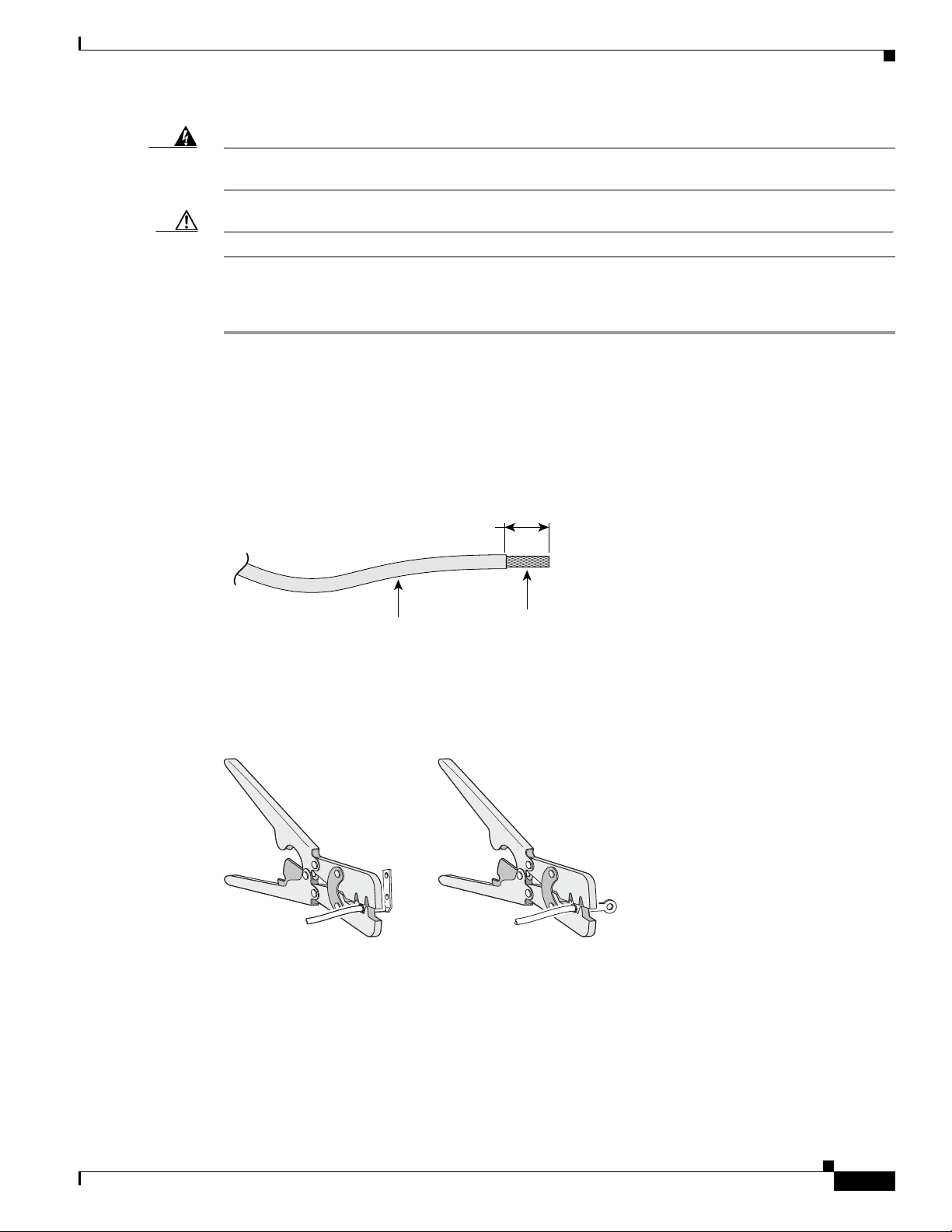
Chapter 4 Power Supply Installation
Insulation
Wire lead
0.5 in. (12.7 mm) ± 0.02 in. (0.5 mm)
60528
33
4022
Installing a DC Power Supply
Warning
Caution Follow the grounding procedure instructions, and use a UL-listed lug (included in the accessory kit).
When installing or replacing the unit, the ground connection must always be made first and
disconnected last.
Statement 1046
Follow these steps to install either a single-ground lug or a dual-ground lug on the switch. Make sure to
follow any grounding requirements at your site.
Step 1 Use the ground lug screw and the lug ring for a single-ground connection. Use the dual-ground adapter
and dual-hole lug for a dual-ground connection.
Step 2 Strip the 12-gauge or 8-gauge ground wire to 0.5 inch (12.7 mm) ± 0.02 inch (0.5 mm) (Figure 4-8).
Stripping more than the recommended amount of wire can leave exposed wire from the connector. Use
12-gauge copper ground wire for the single-ground connection. Use 8-gauge copper ground wire for the
dual-ground connection.
Figure 4-8 Stripping the Ground Wire
Step 3 Slide the open end of the ground lug over the exposed area of the wire.
Step 4 Using a Panduit crimping tool, crimp the ground lug to the wire (Figure 4-9).
Figure 4-9 Crimping the Ground Lug
Step 5
Use the ground screw to attach the single-ground lug to the switch rear panel. Use two ground screws to
attach the dual-hole lug to the switch rear panel (Figure 4-10).
Step 6 Using a ratcheting torque screwdriver, torque the ground-lug screws to 60 lbf-in. (960 ozf-in.).
Step 7 Connect the other end of the grounding wire to an appropriate grounding point at your site or to the rack.
OL-26779-02
Catalyst 3850 Switch Hardware Installation Guide
4-9
Page 78
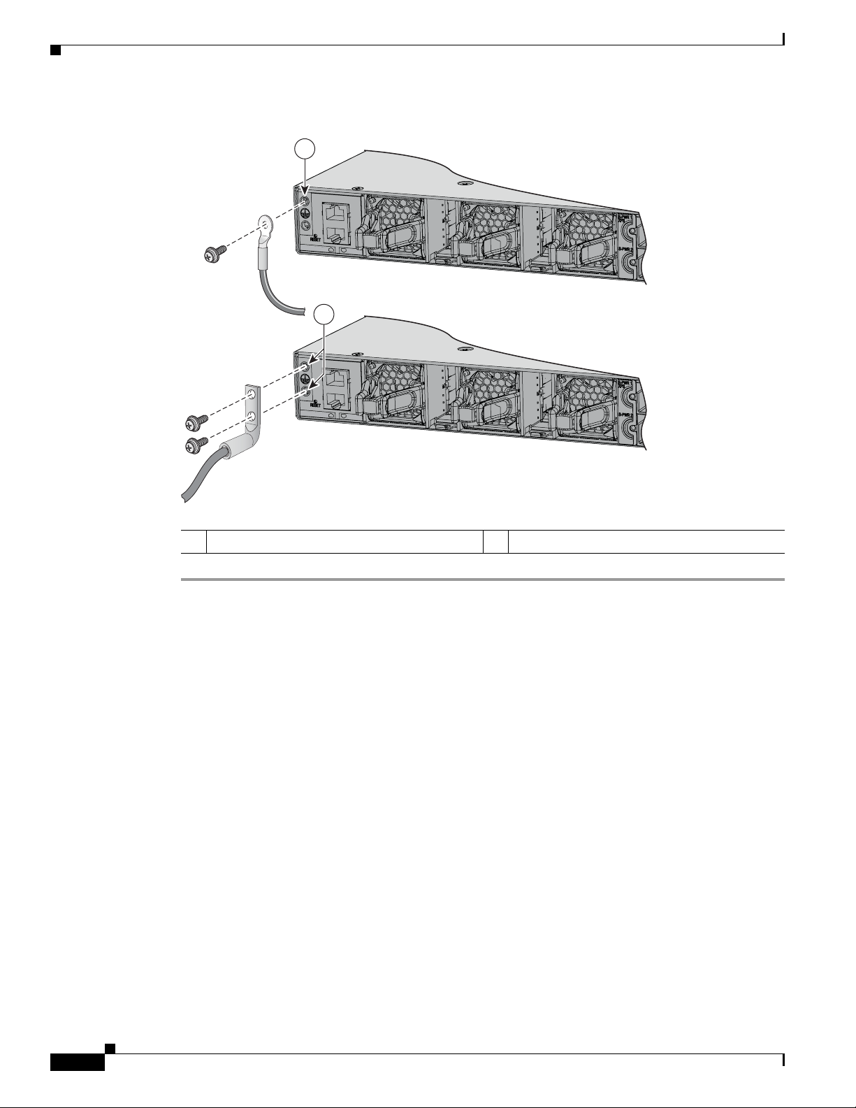
Installing a DC Power Supply
344193
1
2
CONSOLE
MGMT
CONSOLE
MGMT
Figure 4-10 Attaching the Ground Lug and Wire Assembly
Chapter 4 Power Supply Installation
1 Single-ground screw and lug ring 2 Dual-ground adapter and dual-hole lug
4-10
Catalyst 3850 Switch Hardware Installation Guide
OL-26779-02
Page 79
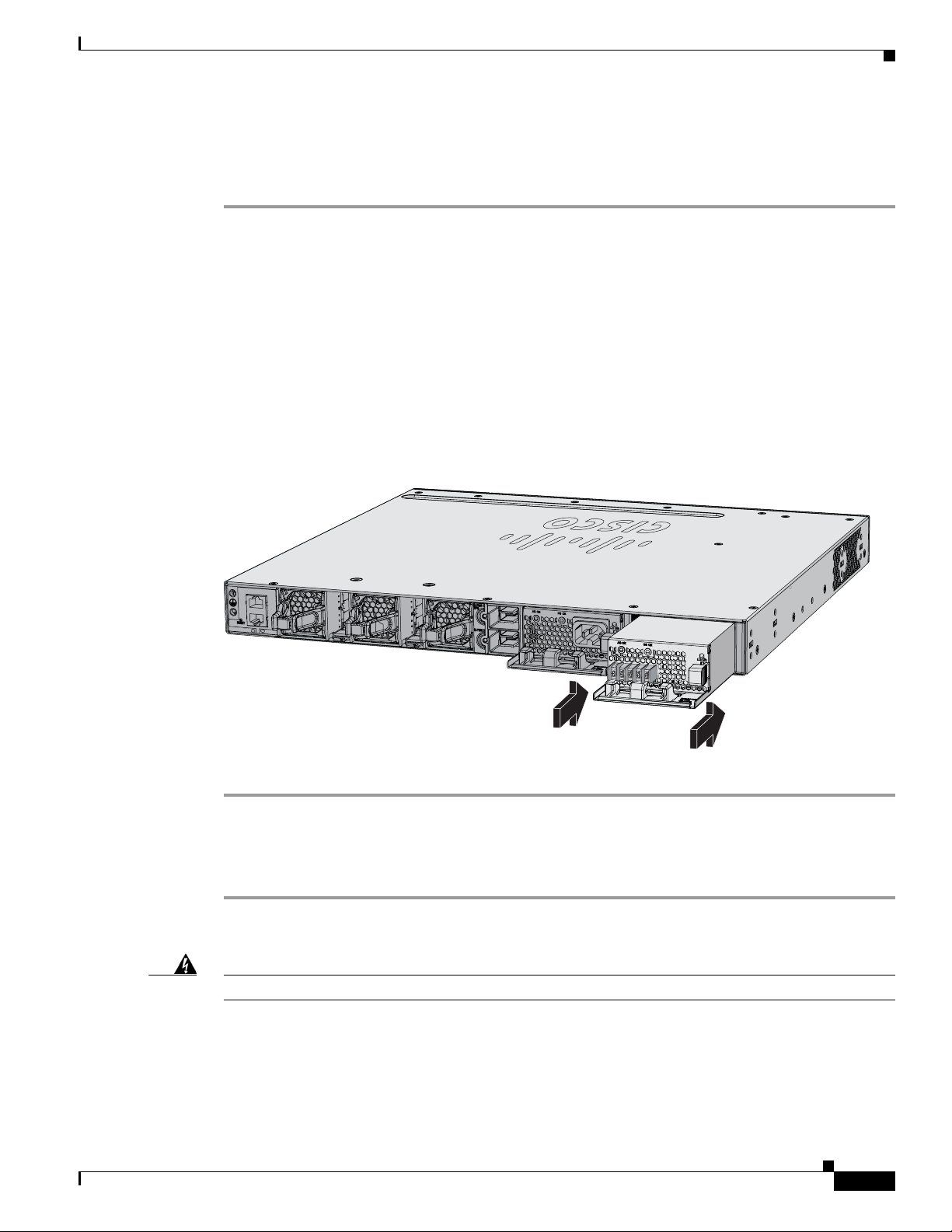
Chapter 4 Power Supply Installation
334077
PWR-C1-715WAC
PWR-C1-440WDC
CONSOLE
MGMT
Installing the DC Power Supply in the Switch
Before installing the power supply, see the Installation Guidelines, page 4-5.
Step 1 Turn off DC power. To ensure that power is off, change the circuit breakers to the OFF position, and
tape the circuit-breaker switches in the OFF position.
Step 2 Remove the plastic safety cover from the power supply terminal blocks (Figure 4-4).
If you are not replacing a DC power supply, go to Step 5.
Step 3 Use a number-2 Phillips screwdriver to remove the DC-input power wires from the power terminals.
Step 4 Press the release latch at the right side of the power supply module inward, and pull the power supply
out.
Step 5 Insert the power supply in the power-supply slot, and gently push it into the slot (Figure 4-11). When
correctly installed, the DC power supply (excluding the extraction handle) is flush with the switch rear
panel.
Figure 4-11 Inserting the DC Power Supply in the Switch
Installing a DC Power Supply
Step 6
Connect the input power as described in the “Wiring the DC Input Power Source” section.
Wiring the DC Input Power Source
Step 1 Using a wire-stripping tool, strip each of the four wires from the DC-input power source to the
appropriate length for the terminals.
Warning
Step 2 Using a Panduit crimping tool, crimp the fork-type terminals to the copper conductor, 90C, 14-AWG DC
OL-26779-02
Use copper conductors only.
power input wires.
Statement 1025
Catalyst 3850 Switch Hardware Installation Guide
4-11
Page 80

Finding the Power Supply Module Serial Number
Step 3 Connect the DC-input power terminals to the terminal blocks. See Figure 4-12 or Figure 4-13. Make sure
to match the polarity (negative to negative, positive to positive) when connecting the wires to the
terminal blocks. Connect the ground wire to a grounded metal rack or to earth ground if the switch is not
in a grounded rack.
Figure 4-12 DC Source A Isolated From Source B with No Common Ground
Chapter 4 Power Supply Installation
A+
+
Figure 4-13 DC Source A and Source B Connections with Common Ground
A+
+
Step 4
Step 5 Replace the terminal block safety cover.
Torque all terminal block screws to 11 lbf-in.
A-
-
A-
-
B-
B-
B+
253447
-
+
B+
253446
-
+
Step 6 Move the DC power source circuit-breakers to the ON position.
Step 7 Confirm that the power supply DC OK and PS OK LEDs are green. See Tab le 4-2 for a description of
the module LEDs.
Finding the Power Supply Module Serial Number
If you contact Cisco Technical Assistance regarding a power supply module, you need to know the serial
number. See Figure 4-14 to Figure 4-16 to find the serial number. You can also use the CLI to find out
the serial number.
Catalyst 3850 Switch Hardware Installation Guide
4-12
OL-26779-02
Page 81

Chapter 4 Power Supply Installation
Figure 4-14 1100-W AC Power Supply Serial Number
Finding the Power Supply Module Serial Number
SN: XXXNNNNXXXX
PWR-C1-1100WAC
Figure 4-15 715-W and 350-W AC Power Supply Module Serial Number
SN: XXXNNNNXXXX
334334, 781-00765-01
334333,781-00764-01
OL-26779-02
PWR-C1-715WAC
Catalyst 3850 Switch Hardware Installation Guide
4-13
Page 82

Finding the Power Supply Module Serial Number
Figure 4-16 440-W DC Power Supply Module Serial Number
Chapter 4 Power Supply Installation
SN: XXXNNNNXXXX
334335, 781-00763-01
PWR-C1-440WDC
4-14
Catalyst 3850 Switch Hardware Installation Guide
OL-26779-02
Page 83

Overview
CHAP T E R
5
Installing the Fan
This chapter describes how to install a fan module.
• Overview, page 5-1
• Fan Module Installation, page 5-2
• Finding the Fan Module Serial Number, page 5-3
The switch has three fan modules. Fan modules are hot-swappable. A powered switch should always
have more than one operational fan. The switch can operate with two operational fans and one
nonfunctional fan, but the failed fan should be replaced as soon as possible to avoid a service
interruption due to a second fan fault.
Note Three fans are required for proper cooling.
OL-26779-02
Catalyst 3850 Switch Hardware Installation Guide
5-1
Page 84

Fan Module Installation
Chapter 5 Installing the Fan
Figure 5-1 Fan Module
1
4
1 Fan LED 3 Retainer clip
2 Exhaust vent 4 Extraction handles
2
Fan Module Installation
3
344200
Installation Guidelines
Observe these guidelines when removing or installing a fan module:
• Do not force the fan module into the slot. This can damage the pins on the switch if they are not
aligned with the module.
• A fan module that is only partially connected can disrupt the system operation.
• The switch supports hot swapping of the fan module. You can remove and replace the module
without interrupting normal switch operation.
Warning
Only trained and qualified personnel should be allowed to install, replace, or service this equipment.
Statement 1030
Installing a Fan Module
Step 1 Pinch the fan module release handle, and slide the module out.
Caution You should replace the fan module within 5 minutes to avoid overheating the switch.
5-2
Catalyst 3850 Switch Hardware Installation Guide
OL-26779-02
Page 85

Chapter 5 Installing the Fan
344201
PWR-C1-715WAC
PWR-C1-715WAC
CONSOLE
MGMT
1
Step 2 Install the fan module in the fan slot, and firmly push it into the slot, applying pressure to the end of the
module, not the extraction handles. When correctly inserted, the fan module is flush with the switch rear
panel. When the fan is operating, a green LED is on in the top left corner of the fan. See Figure 5-2.
Finding the Fan Module Serial Number
Warning
Do not reach into a vacant slot when installing or removing a module. Exposed circuitry is an energy
hazard.
Statement 206
Figure 5-2 Installing the Fan Module
1 Fan LED
Finding the Fan Module Serial Number
If you contact Cisco Technical Assistance regarding a fan module, you need to know the fan module
serial number. See Figure 5-3 for the serial number location.
Catalyst 3850 Switch Hardware Installation Guide
OL-26779-02
5-3
Page 86

Finding the Fan Module Serial Number
SN: XXXNNNNXXXX
334328,781-00761-01
Figure 5-3 Fan Module Serial Number
Chapter 5 Installing the Fan
5-4
Catalyst 3850 Switch Hardware Installation Guide
OL-26779-02
Page 87

Troubleshooting
• Diagnosing Problems, page 6-1
• Resetting the Switch, page 6-5
• Finding the Switch Serial Number, page 6-6
• Replacing a Failed Data Stack Member, page 6-6
Diagnosing Problems
The switch LEDs provide troubleshooting information about the switch. They show POST failures,
port-connectivity problems, and overall switch performance. You can also get statistics from the CLI,
or an SNMP workstation. See the software configuration guide, the switch command reference guide on
Cisco.com, or the documentation that came with your SNMP application for details.
CHAP T E R
6
Switch POST Results
Approximately 30 seconds after the switch powers on, it begins the power-on self-test (POST), which
can take up to 5 minutes to complete. During POST, the SYSTEM LED blinks green. When POST is
complete, the SYSTEM LED turns solid green, the ACTV LED is green if the switch is acting as the
active switch.
Note POST failures are usually fatal. Contact your Cisco technical support representative if your switch does
not pass POST.
Switch LEDs
Look at the port LEDs for information when troubleshooting the switch. See the “LEDs” section on
page 1-9 for descriptions of the LED colors and their meanings.
OL-26779-02
Catalyst 3850 Switch Hardware Installation Guide
6-1
Page 88

Diagnosing Problems
Switch Connections
Bad or Damaged Cable
Always examine the cable for marginal damage or failure. A cable might be just good enough to connect
at the physical layer, but it could corrupt packets as a result of subtle damage to the wiring or connectors.
You can identify this situation because the port has many packet errors or the port constantly flaps (loses
and regains link).
• Exchange the copper or fiber-optic cable with a known good cable.
• Look for broken or missing pins on cable connectors.
• Rule out any bad patch panel connections or media convertors between the source and destination.
If possible, bypass the patch panel or eliminate media convertors (fiber-optic-to-copper).
• Try the cable in another port to see if the problem follows the cable.
• For Catalyst 3850 switch StackWise cable, remove and inspect the cable and StackWise port for bent
pins or damaged connectors. If the StackWise cable is bad, replace it with a known good cable.
Chapter 6 Troubleshooting
Ethernet and Fiber Cables
Make sure that you have the correct cable:
• For Ethernet, use Category 3 copper cable for 10 Mbps UTP connections. Use either Category 5,
Category 5e, or Category 6 UTP for 10/100 or 10/100/1000 Mbps connections.
• Verify that you have the correct fiber-optic cable for the distance (100 meters or less) and port type.
Make sure that the connected device ports match and use the same type encoding, optical frequency,
and fiber type. For more information about cabling, see the “SFP and SFP+ Module Cable
Specifications” section on page B-5.
• Determine if a copper crossover cable was used when a straight-through was required, or the
reverse. Enable auto-MDIX on the switch, or replace the cable. See Tab le 2-2 for recommended
Ethernet cables.
Link Status
Verify that both sides have a link. A broken wire or a shut-down port can cause one side to show a link
even though the other side does not have a link.
A port LED that is on does not guarantee that the cable is functional. It might have encountered physical
stress, causing it to function at a marginal level. If the port LED does not turn on:
• Connect the cable from the switch to a known good device.
• Make sure that both ends of the cable are connected to the correct ports.
• Verify that both devices have power.
• Verify that you are using the correct cable type. See Appendix B, “Connector and Cable
Specifications” for more information.
6-2
• Look for loose connections. Sometimes a cable appears to be seated but is not. Disconnect the cable
and then reconnect it.
Catalyst 3850 Switch Hardware Installation Guide
OL-26779-02
Page 89

Chapter 6 Troubleshooting
10/100/1000 Port Connections
A port appears to malfunction:
• Verify the status of all ports. See Table 1-5 on page 1-11 for descriptions of the LEDs and their
meanings.
• Use the show interfaces privileged EXEC command to see if the port is error-disabled, disabled, or
shut down. Reenable the port if necessary.
• Verify the cable type. See Appendix B, “Connector and Cable Specifications.”
PoE and PoE+ Port Connections
A powered device connected to a PoE port does not receive power:
• Verify the status of all ports. See Tab l e 1-6 and Ta b le 1-10 for descriptions of the LEDs and their
meanings.
• Use the show interfaces privileged EXEC command to see if the port is error-disabled, or disabled,
or shut down. Reenable the port if necessary.
• Verify that the power supply installed in the switch meets the power requirements of your connected
devices. See the “Power Supply Modules” section on page 1-18 for more information.
• Verify the cable type. Many legacy powered devices, including older Cisco IP phones and access
points that do not fully support IEEE 802.3af might not support PoE when connected to the switch
by a crossover cable. Replace the crossover cable with a straight-through cable.
Diagnosing Problems
Caution Noncompliant cabling or powered devices can cause a PoE port fault. Use only compliant cabling to
Note The output of the PoE circuit has been evaluated as a limited power source (LPS) per IEC 60950.
SFP Modules
connect Cisco prestandard IP phones, wireless access points, or IEEE 802.3af-compliant devices.
Use only Cisco network modules and SFP modules.
• Inspect the network module and SFP module. Exchange the suspect module with a known good
module.
• Verify that the module is supported on this platform. (The switch release notes on Cisco.com list the
SFP and SFP+ modules that the switch supports.)
• Use the show interfaces privileged EXEC command to see if the port or module is error-disabled,
disabled, or shut down. Reenable the port if needed.
• Make sure that all fiber connections are clean and securely connected.
• For CX1 module connections and fiber connections, make sure that cable routing does not violate
the minimum allowed cable bend radius. See the module documentation for specific cabling
requirements.
OL-26779-02
Catalyst 3850 Switch Hardware Installation Guide
6-3
Page 90

Diagnosing Problems
Interface Settings
Ping End Device
Chapter 6 Troubleshooting
Note When ordering or using CX1 cables, ensure that the version identifier is 2 or higher.
• For long wave SFP+ modules, a mode conditioning patch might improve performance over
maximum link distances with MMF connections.
Verify that the port or interface is not disabled or powered off. If a port or interface is manually shut
down on either side of the link, it does not come up until you reenable the interface. Use the show
interfaces privileged EXEC command to see if the interface is error-disabled, disabled, or shut down on
either side of the connection. If needed, reenable the interface.
Ping from the directly connected switch first, and then work your way back port by port, interface by
interface, trunk by trunk, until you find the source of the connectivity issue. Make sure that each switch
can identify the end device MAC address in its Content-Addressable Memory (CAM) table.
Spanning Tree Loops
STP loops can cause serious performance issues that look like port or interface problems.
A unidirectional link can cause loops. It occurs when the traffic sent by the switch is received by the
neighbor, but the traffic from the neighbor is not received by the switch. A broken cable, other cabling
problems, or a port issue could cause this one-way communication.
You can enable UniDirectional Link Detection (UDLD) on the switch to help identify unidirectional link
problems. For information about enabling UDLD on the switch, see the “Understanding UDLD” section
in the software configuration guide on Cisco.com.
Switch Performance
Speed, Duplex, and Autonegotiation
Port statistics that show a large amount of alignment errors, frame check sequence (FCS), or
late-collisions errors, might mean a speed or duplex mismatch.
A common issue occurs when duplex and speed settings are mismatched between two switches, between
a switch and a router, or between the switch and a workstation or server. Mismatches can happen when
manually setting the speed and duplex or from autonegotiation issues between the two devices.
To maximize switch performance and to ensure a link, follow one of these guidelines when changing the
duplex or the speed settings:
• Let both ports autonegotiate both speed and duplex.
• Manually set the speed and duplex parameters for the interfaces on both ends of the connection.
6-4
• If a remote device does not autonegotiate, use the same duplex settings on the two ports. The speed
parameter adjusts itself even if the connected port does not autonegotiate.
Catalyst 3850 Switch Hardware Installation Guide
OL-26779-02
Page 91

Chapter 6 Troubleshooting
Autonegotiation and Network Interface Cards
Problems sometimes occur between the switch and third-party network interface cards (NICs). By
default, the switch ports and interfaces autonegotiate. Laptops or other devices are commonly set to
autonegotiate, yet sometimes issues occur.
To troubleshoot autonegotiation problems, try manually setting both sides of the connection. If this does
not solve the problem, there could be a problem with the firmware or software on the NIC. You can
resolve this by upgrading the NIC driver to the latest version.
Cabling Distance
If the port statistics show excessive FCS, late-collision, or alignment errors, verify that the cable
distance from the switch to the connected device meets the recommended guidelines. See the “Cable and
Adapter Specifications” section on page B-5.
Resetting the Switch
Resetting the Switch
If you have configured a new switch with a wrong IP address, or if all of the switch LEDs start blinking
when you try to enter Express Setup mode, you can clear the IP address that is configured on the switch.
Note Resetting the switch reboots the switch.
To reset the switch:
1. Press and hold the Mode button (Figure 1-2 on page 1-5).
The switch LEDs begin blinking after about 2 seconds. If the LEDs above the mode button turn solid
green, you can release the Mode button and run Express Setup to configure the switch. If the LEDs
do not turn solid green, continue with the next step.
2. Continue holding down the Mode button. The LEDs stop blinking after an additional 8 seconds, and
then the switch reboots.
Alternatively, you can press the Reset button on the rear of the switch (approximately 5 seconds) to
power cycle the switch.
You can also configure the switch by using the CLI setup procedure. See Appendix C, “Configuring the
Switch with the CLI-Based Setup Program.”
OL-26779-02
Catalyst 3850 Switch Hardware Installation Guide
6-5
Page 92
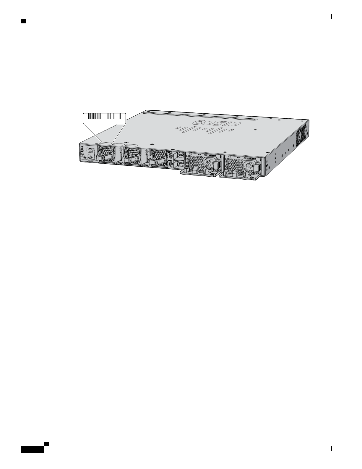
Finding the Switch Serial Number
Finding the Switch Serial Number
If you contact Cisco Technical Assistance, you need to know the switch serial number. Figure 6-1 shows
the serial number location. You can also use the show version privileged EXEC command to see the
switch serial number.
Figure 6-1 Switch Serial Number Location
SN: XXXNNNNXXXX
CONSOLE
MGMT
Chapter 6 Troubleshooting
334103, 781-00760-01
Replacing a Failed Data Stack Member
To replace a failed data stack member:
1. The replacement switch must be a Catalyst 3850 switch.
2. Power down the failed switch. Remove AC or DC input power, and if the switch is part of a
StackPower stack, remove the StackPower cables.
3. Make sure the replacement switch is powered off, and then connect it to the stack.
If you had manually set the member numbers for the switch stack, manually assign the member
number of the failed switch to the replacement switch. To manually assign the stack member
number, see the switch software configuration guide on Cisco.com.
4. Make the same Gigabit Ethernet connections on the replacement switch that were on the failed
switch.
5. Reinstall any modules and cable connections.
6. Power on the replacement switch.
The replacement switch will have the same configuration for all the interfaces as the failed switch and
will function the same as the failed switch.
6-6
Catalyst 3850 Switch Hardware Installation Guide
OL-26779-02
Page 93

Technical Specifications
• Switch Specifications, page A-1
• Power Supply Module Specifications, page A-2
• Fan Module Specifications, page A-4
Switch Specifications
Table A-1 Environmental and Physical Specifications
Environmental Ranges
Operating
Storage temperature –40 to 158° F (–40 to 70° C)
Relative humidity 5 to 95% (non-condensing)
Operating altitude Up to 10,000 ft (3,000 m)
Storage altitude Up to 15,000 ft (4,600 m)
Physical Specifications
Dimensions (H x W x D) 1.73 x 17.5 x 17.5 in. (4.4 x 44.5 x 44.5 cm)
Weight
1
temperature
APPENDIX
23 to 113° F (–5 to 45° C)
(with the FAN FRUs installed but without the power
supplies installed)
(weights do not include the network modules, power
supplies, or blanks).
A
OL-26779-02
Catalyst 3850 24-port PoE switches
Catalyst 3850 24-port non PoE switches
Catalyst 3850 48-port non PoE switches
Catalyst 3850 48-port PoE switches
1. Minimum ambient temperature for cold start is 32° F (0° C)
13.3 lb (6.0 kg)
13.1 lbs (6.0 kg)
14.2 lbs (6.5 kg)
14.4 lbs (6.5)
Catalyst 3850 Switch Hardware Installation Guide
A-1
Page 94

Power Supply Module Specifications
Power Supply Module Specifications
Table A-2 Environmental and Physical Specifications for the AC- and DC-Power Supply
Modules
Environmental Ranges
Operating temperature AC power supply: 23 to 113° F (–5 to 45° C)
DC power supply: 23 to 131° F (–5 to 55° C)
Storage temperature –40 to 158° F (–40 to 70° C)
Relative humidity 10 to 95% (non-condensing)
Altitude AC power supply: Up to 10,000 ft (3,000 m)
DC power supply: Up to 13,000 ft (4,000 m)
Physical Specifications
Weight
PWR-C1-1100WAC
PWR-C1-715WAC
3 lb (1.4 kg)
2.8 lb (1.3 kg)
Appendix A Technical Specifications
PWR-C1-350WAC
PWR-C1-440WDC=
Dimensions (H x D x W)
PWR-C1-1100WAC
PWR-C1-715WAC
PWR-C1-350WAC
PWR-C1-440WDC=
Table A-3 Power Specifications for AC Power 24- and 48-Port Switches
Power Specifications
Maximum output power PWR-C1-1100WAC: 1100 W
Input voltage range and frequency PWR-C1-1100WAC: 1100-W, 115 to 240 VAC (autoranging)
Input current PWR-C1-1100WAC:12–6 A
2.6 lb (1.2 kg)
2.6 lb (1.2 kg)
1.58 x 11.72 x 3.25 in. (3.5 x 29.8 x 8.3 cm)
1.58 x 10.22 x 3.25 in. (3.5 x 26 x 8.3 cm)
1.58 x 10.22 x 3.25 in. (3.5 x 26 x 8.3 cm)
1.58 x 10.22 x 3.25 in. (3.5 x 26 x 8.3 cm)
Note Dimensions shown exclude the extraction handle, which
measures 1.55 in. (3.9 cm) and the keying feature which
measures 0.44 in (1.1 cm).
PWR-C1-715WAC: 715 W
PWR-C1-350WAC: 350 W
50 to 60 Hz
PWR-C1-715WAC: 715 W, PWR-C1-350WAC: 350 W,
100 to 240 VAC (autoranging), 50 to 60 Hz
PWR-C1-715WAC: 10–5 A
PWR-C1-350WAC: 4–2 A
A-2
Catalyst 3850 Switch Hardware Installation Guide
OL-26779-02
Page 95

Appendix A Technical Specifications
Table A-3 Power Specifications for AC Power 24- and 48-Port Switches (continued)
Output ratings PWR-C1-1100WAC: –56 V@19.64 A
Total input BTU
Total output BTU
1. The total input and total output BTU ratings refer to input power to the power supply and output power to the switch. The
BTU ratings are based on 100 VAC for the 350-W and 715-W power supplies and 115 VAC for the 1100-W power supply.
Table A-4 Power Specifications for DC-Power 24- and 48-Port Switches
Power Specifications
Maximum output power PWR-C1-440WDC: 440 W
Input current PWR-C1-440WDC: 16 –8 A
DC input voltage PWR-C1-440WDC: –36 to –72 VDC
Output ratings PWR-C1-440WDC: –56 V@7.86 A
Voltage range domestic PWR-C1-440WDC: –36 VDC (minimum)
Voltage range international PWR-C1-440WDC: –36 VDC (minimum)
Total input BTU
Total output BTU
Wire gauge for ground connection PWR-C1-440WDC: 12 AWG or 8 AWG
Branch circuit protection PWR-C1-440WDC: 20 A
1. The total input and total output BTU ratings refer to input power to the power supply and output power to the switch. The
BTU ratings are based on –36 VDC.
Power Supply Module Specifications
PWR-C1-715WAC: –56 V@12.8 A
PWR-C1-350WAC: –56 V@6.25 A
1
1
1
1
PWR-C1-1100WAC: 4263 BTUs per hour, 1250 W
PWR-C1-715WAC: 2742 BTUs per hour, 804 W
PWR-C1-350WAC: 1357 BTUs per hour, 398 W
PWR-C1-1100WAC: 3751 BTUs per hour, 1100 W
PWR-C1-715WAC: 2438 BTUs per hour, 765 W
PWR-C1-350WAC: 1194 BTUs per hour, 350 W
–48 VDC (nominal), –72 VDC (maximum)
–60 VDC (nominal), –72 VDC (maximum)
PWR-C1-440WDC 1841 BTUs per hour, 540 W
PWR-C1-440WDC: 1502 BTUs per hour, 440 W
OL-26779-02
Catalyst 3850 Switch Hardware Installation Guide
A-3
Page 96

Fan Module Specifications
Fan Module Specifications
Table A-5 Fan Module Environmental and Physical Specifications
Environmental Ranges
Operating temperature 23 to 176° F (–5 to 80° C)
Storage temperature –40 to 185° F (–40 to 85° C)
Relative humidity 5 to 95% (non-condensing)
Altitude Up to 13,000 ft (4,000 m)
Physical Specification
Dimensions (H x D x W) 1.62 x 1.73 x 4.24 in. (4.11 x 4.39 x 10.76 cm)
Weight 0.2 lb (0.07 kg)
Operating Specification
Airflow 20 cfm
Appendix A Technical Specifications
A-4
Catalyst 3850 Switch Hardware Installation Guide
OL-26779-02
Page 97

2 3145678Pin Label
1
2
3
4
5
6
7
8
TP0+
TP0-
TP1+
TP2+
TP2-
TP1-
TP3+
TP3-
Connector and Cable Specifications
This chapter describes the connector and cable specifications.
• Connector Specifications, page B-1l
• Cable and Adapter Specifications, page B-5
Connector Specifications
• 10/100/1000 Ports, page B-1
• 10-Gigabit Ethernet CX1 (SFP+ Copper) Connectors, page B-2
• SFP and SFP+ Modules, page B-2
• 10/100/1000 Ethernet Management Port, page B-3
• Console Port, page B-4
APPENDIX
B
10/100/1000 Ports
OL-26779-02
The 10/100/1000 Ethernet ports on switches use RJ-45 connectors and Ethernet pinouts.
Figure B-1 10/100/1000 Port Pinouts
Catalyst 3850 Switch Hardware Installation Guide
B-1
Page 98

Connector Specifications
278541
58476
10-Gigabit Ethernet CX1 (SFP+ Copper) Connectors
The 10-Gigabit Ethernet electrical modules use CX1 copper connectors similar to the one shown in
Figure B-2.
Note When ordering or using CX1 cables, ensure that the version identifier is 2 or higher.
The 10-Gigabit Ethernet optical modules use the connectors shown in Figure B-3 and Figure B-4.
Figure B-2 10-Gigabit Ethernet CX1 Copper Connector (example)
Appendix B Connector and Cable Specifications
SFP and SFP+ Modules
Figure B-3, Figure B-4, and Figure B-5 show the SFP module connectors.
The switch supports the SFP module patch cable, a 0.5-meter, copper, passive cable with SFP module
connectors at each end (Figure B-6). This cable can be used (only with 1-Gigabit Ethernet SFP ports) to
connect two Catalyst 3850 switches in a cascaded configuration.
Figure B-3 Duplex LC Cable Connector
B-2
Catalyst 3850 Switch Hardware Installation Guide
OL-26779-02
Page 99

Appendix B Connector and Cable Specifications
57834
60915
2 3145678Pin Label
1
2
3
4
5
6
7
8
TP0+
TP0-
TP1+
TP2+
TP2-
TP1-
TP3+
TP3-
126809
Figure B-4 Simplex LC Cable Connector
Figure B-5 Copper SFP Module RJ-45 Connector
Connector Specifications
Figure B-6 SFP Module Patch Cable
10/100/1000 Ethernet Management Port
The 10/100/1000 Ethernet management port uses RJ-45 connectors with Ethernet pinouts. Figure B-7
shows the pinouts.
OL-26779-02
Catalyst 3850 Switch Hardware Installation Guide
B-3
Page 100

Connector Specifications
H5318
2 3145678Pin Label
1
2
3
4
5
6
7
8
RD+
RD-
TD+
NC
NC
TD-
NC
NC
345493
Console Port
Appendix B Connector and Cable Specifications
Figure B-7 10/100 Port Pinouts
The switch has two console ports: a USB 5-pin mini-Type B port on the front panel (see Figure B-8) and
an RJ-45 console port on the rear panel.
Figure B-8 USB Mini-Type B Port
345492
The USB console port uses a USB Type A to 5-pin mini-Type B cable, shown in Figure B-9. The USB
Type A-to-USB mini-Type B cable is not supplied. You can order an accessory kit (part
number 800-33434) that contains this cable.
Figure B-9 USB Type A-to-USB 5-Pin Mini-Type B Cable
B-4
Catalyst 3850 Switch Hardware Installation Guide
OL-26779-02
 Loading...