

Page 1

Cisco Smart Install Configuration Guide
December 10, 2014
Cisco Systems, Inc.
www.cisco.com
Cisco has more than 200 offices worldwide.
Addresses, phone numbers, and fax numbers
are listed on the Cisco website at
www.cisco.com/go/offices.
Text Part Number: OL-28027-01
Page 2

THE SPECIFICATIONS AND INFORMATION REGARDING THE PRODUCTS IN THIS MANUAL ARE SUBJECT TO CHANGE WITHOUT NOTICE. ALL
STATEMENTS, INFORMATION, AND RECOMMENDATIONS IN THIS MANUAL ARE BELIEVED TO BE ACCURATE BUT ARE PRESENTED WITHOUT
WARRANTY OF ANY KIND, EXPRESS OR IMPLIED. USERS MUST TAKE FULL RESPONSIBILITY FOR THEIR APPLICATION OF ANY PRODUCTS.
THE SOFTWARE LICENSE AND LIMITED WARRANTY FOR THE ACCOMPANYING PRODUCT ARE SET FORTH IN THE INFORMATION PACKET THAT
SHIPPED WITH THE PRODUCT AND ARE INCORPORATED HEREIN BY THIS REFERENCE. IF YOU ARE UNABLE TO LOCATE THE SOFTWARE LICENSE
OR LIMITED WARRANTY, CONTACT YOUR CISCO REPRESENTATIVE FOR A COPY.
The Cisco implementation of TCP header compression is an adaptation of a program developed by the University of California, Berkeley (UCB) as part of UCB’s public
domain version of the UNIX operating system. All rights reserved. Copyright © 1981, Regents of the University of California.
NOTWITHSTANDING ANY OTHER WARRANTY HEREIN, ALL DOCUMENT FILES AND SOFTWARE OF THESE SUPPLIERS ARE PROVIDED “AS IS” WITH
ALL FAULTS. CISCO AND THE ABOVE-NAMED SUPPLIERS DISCLAIM ALL WARRANTIES, EXPRESSED OR IMPLIED, INCLUDING, WITHOUT
LIMITATION, THOSE OF MERCHANTABILITY, FITNESS FOR A PARTICULAR PURPOSE AND NONINFRINGEMENT OR ARISING FROM A COURSE OF
DEALING, USAGE, OR TRADE PRACTICE.
IN NO EVENT SHALL CISCO OR ITS SUPPLIERS BE LIABLE FOR ANY INDIRECT, SPECIAL, CONSEQUENTIAL, OR INCIDENTAL DAMAGES, INCLUDING,
WITHOUT LIMITATION, LOST PROFITS OR LOSS OR DAMAGE TO DATA ARISING OUT OF THE USE OR INABILITY TO USE THIS MANUAL, EVEN IF CISCO
OR ITS SUPPLIERS HAVE BEEN ADVISED OF THE POSSIBILITY OF SUCH DAMAGES.
Cisco and the Cisco logo are trademarks or registered trademarks of Cisco and/or its affiliates in the U.S. and other countries. To view a list of Cisco trademarks, go to this
URL: www.cisco.com/go/trademarks. Third-party trademarks mentioned are the property of their respective owners. The use of the word partner does not imply a partnership
relationship between Cisco and any other company. (1110R)
Any Internet Protocol (IP) addresses and phone numbers used in this document are not intended to be actual addresses and phone numbers. Any examples, command display
output, network topology diagrams, and other figures included in the document are shown for illustrative purposes only. Any use of actual IP addresses or phone numbers in
illustrative content is unintentional and coincidental.
Cisco Smart Install Configuration Guide
© 2009-2014 Cisco Systems, Inc. All rights reserved.
Page 3

CONTENTS
Introduction 1-1
Smart Install Director 1-3
Image List File 1-5
Configuration Files 1-6
Smart Install Clients 1-6
Smart Install Groups 1-9
DHCP and Smart Install 1-10
Adding a Client Switch to the Network 1-11
Backing Up the Client Configuration 1-12
Replacing a Client Switch 1-12
Using a Join Window 1-13
Configuring Join Window Mode 1-14
Updating Client Switches 1-15
Zero-Touch Installation 1-15
Contents
Connecting to a Client Switch 1-16
Configuration Guidelines and Recommendations 2-1
DHCP Configuration Guidelines 2-4
Configuring the DHCP Server 2-4
Configuring the Director as the DHCP Server 2-5
Configuring Another Device as DHCP Server 2-6
Configuring the TFTP Server 2-8
Establishing a Remote Client Session 2-8
Configuring a Network with Single or Mixed Switch Types 2-9
Configuring a Network That Includes a Single Switch Type 2-9
Using Built-In Groups to Configure a Mixed Network with Two Switch Types 2-12
Updating On-Demand to a New Image or Configuration 2-16
Configuring Custom Group Based on Connectivity 2-19
Configuring a Custom Group Based on MAC Address 2-21
Configuring a Custom Group Based on a Stack Number 2-23
Custom Group Based on Product ID 2-26
Managing Client Configuration Files 2-28
Backing Up Files after Loss of Connection 2-28
Extracting and Displaying Tar Files 2-28
OL-28027-01
Other Configuration Options 2-29
Disabling Smart Install on a Device 2-29
Managing File Downloads on Clients 2-29
Download Management for Non-Smart Install Clients 2-29
Cisco Smart Install Configuration Guide
iii
Page 4

Contents
Download Management for Smart Install Clients 2-29
Configuring a Client Hostname Prefix 2-30
Configuring Additional Smart Install Management VLANs 2-30
Configuring a Group for Standalone Catalyst 4500 Series Switch 2-31
Restrictions and Guidelines 2-32
The Procedure 2-32
On-Demand Upgrade for Catalyst 4500 Series Switch IBC 2-36
Support for Post-install Operations 2-37
Configure a Script for Default Mode 2-38
Configure a Script for the Built-in Group Mode 2-39
Configure a Script for Custom Group Mode 2-40
Smart Install Configuration Examples 2-41
Director as the TFTP Server 2-41
Before Configuring the Director 2-41
Configure a Director 2-42
Third-Party, Non-Cisco IOS Device as the TFTP Server 2-43
Before Configuring the Director 2-43
Configure the Director 2-43
Information about SMI Proxy 4-1
How SMI Proxy Interacts with Smart Install Devices and the PnP Agent 4-2
How SMI Clients and Directors Communicate 4-2
How SMI Proxy and PnP Agent Communicate 4-2
SMI Proxy and Tailored Configuration Files 4-3
SMI Proxy Database 4-3
Enabling Proxy on the Device 4-4
Unsupported Services 4-5
Guidelines and Restrictions 4-6
SMI Proxy CLI Commands 4-7
4-19
SNMP MIBs 5-1
Cisco Smart Install MIB 5-1
Downloading and Working with MIBs 5-2
Guidelines for Working with MIBs 5-2
Downloading MIBs 5-3
System Messages 5-3
How to Read System Messages 5-3
Error Message Traceback Reports 5-4
Output Interpreter 5-4
Bug Toolkit 5-5
iv
Cisco Smart Install Configuration Guide
OL-28027-01
Page 5

Smart Install System Messages 5-5
Minimum Cisco IOS Release for Major Features C-1
Contents
OL-28027-01
Cisco Smart Install Configuration Guide
v
Page 6

Contents
vi
Cisco Smart Install Configuration Guide
OL-28027-01
Page 7

Preface
This guide provides procedures for installing and using Smart Install and using the related commands.
For information about other standard Cisco IOS Release 12.2 commands or Cisco IOS Release 15.0, see
the Cisco IOS documentation set available from the Cisco.com home page at Products & Services >
Cisco IOS and NX OS Software> Cisco IOS.
This guide does not describe system messages you might encounter or how to install your device. For
more information, see the system message guide and the hardware installation guide for the device.
For documentation updates, and other late information, see the release notes for the specific device for
this release.
Conventions
This publication uses these conventions to convey instructions and information:
Command descriptions use these conventions:
Interactive examples use these conventions:
Notes and cautions use these conventions and symbols:
Note Means reader take note. Notes contain helpful suggestions or references to materials not contained in
this manual.
• Commands and keywords are in boldface text.
• Arguments for which you supply values are in italic.
• Square brackets ([ ]) mean optional elements.
• Braces ({ }) group required choices, and vertical bars ( | ) separate the alternative elements.
• Braces and vertical bars within square brackets ([{ | }]) mean a required choice within an optional
element.
• Terminal sessions and system displays are in screen font.
• Information you enter is in boldface screen font.
• Nonprinting characters, such as passwords or tabs, are in angle brackets (< >).
Cisco Smart Install Configuration Guide
1
Page 8

Caution Means reader be careful. In this situation, you might do something that could result in equipment
damage or loss of data.
Related Publications
• Catalyst 6500 Supervisor Engine 2T-10GE
http://www.cisco.com/en/US/products/hw/switches/ps708/tsd_products_support_series_home.htm
l
• Catalyst 4500
http://www.cisco.com/en/US/products/hw/switches/ps4324/tsd_products_support_series_home.ht
ml
• Catalyst 3850
http://www.cisco.com/en/US/products/ps12686/tsd_products_support_series_home.html
• Catalyst 3750-X
http://www.cisco.com/en/US/products/ps10745/tsd_products_support_series_home.html
• Catalyst 3750-E
http://www.cisco.com/en/US/products/ps7077/tsd_products_support_series_home.html
• Catalyst 3750
http://www.cisco.com/en/US/products/hw/switches/ps5023/tsd_products_support_series_home.ht
ml
• Catalyst 3650
http://preview.cisco.com/en/US/products/ps13133/products_installation_and_configuration_guides
_list.html
• Catalyst 3560
http://www.cisco.com/en/US/products/hw/switches/ps5528/tsd_products_support_series_home.ht
ml
• Catalyst 3560-E
http://www.cisco.com/en/US/products/ps7078/tsd_products_support_series_home.html
• Catalyst 3560-X
http://www.cisco.com/en/US/products/ps10744/tsd_products_support_series_home.html
• Catalyst 2975
http://www.cisco.com/en/US/products/ps10081/tsd_products_support_series_home.html
• Catalyst 2960, Catalyst 2960-S, and Catalyst 2960-SF
http://www.cisco.com/en/US/products/ps6406/tsd_products_support_series_home.html
• Catalyst 2960-X
http://www.cisco.com/en/US/products/ps12995/tsd_products_support_series_home.html
• Catalyst 2960-XR
http://www.cisco.com/en/US/products/ps13078/tsd_products_support_series_home.html
Cisco Smart Install Configuration Guide
2
Page 9

• IE 2000
http://www.cisco.com/c/en/us/support/switches/industrial-ethernet-2000-series-switches/tsd-produ
cts-support-series-home.html
• IE3000
http://www.cisco.com/c/en/us/support/switches/industrial-ethernet-3000-series-switches/tsd-produ
cts-support-series-home.html
• IE3010
http://www.cisco.com/c/en/us/support/switches/industrial-ethernet-3010-series-switches/tsd-produ
cts-support-series-home.html
• EtherSwitch Network Modules
https://www.cisco.com/en/US/docs/ios/lanswitch/configuration/guide/lsw_enet_switch_net_extern
al_docbase_0900e4b18090920b_4container_external_docbase_0900e4b18096f791.html
Obtaining Documentation, Obtaining Support, and Security Guidelines
For information on obtaining documentation, submitting a service request, and gathering additional
information, see the monthly What’s New in Cisco Product Documentation, which also lists all new and
revised Cisco technical documentation, at:
http://www.cisco.com/en/US/docs/general/whatsnew/whatsnew.html
Subscribe to the What’s New in Cisco Product Documentation as a Really Simple Syndication (RSS) feed
and set content to be delivered directly to your desktop using a reader application. The RSS feeds are a free
service and Cisco currently supports RSS version 2.0.
Cisco Smart Install Configuration Guide
3
Page 10

Cisco Smart Install Configuration Guide
4
Page 11

Introduction
CHA PTER
1
Smart Install Overview
• Introduction, page 1-1
• DHCP and Smart Install, page 1-10
• Adding a Client Switch to the Network, page 1-11
• Backing Up the Client Configuration, page 1-12
• Updating Client Switches, page 1-15
• Connecting to a Client Switch, page 1-16
Smart Install is a plug-and-play configuration and image-management feature that provides zero-touch
deployment for new switches. You can ship a switch to a location, place it in the network and power it
on with no configuration required on the device.
A network using Smart Install includes a group of networking devices, known as clients, that are served
by a common Layer 3 switch or router that acts as a director. In a Smart Install network, you can use the
Zero-Touch Installation process to install new access layer switches into the network without any
assistance from the network administrator. The director provides a single management point for images
and configuration of client switches. When a client switch is first installed into the network, the director
automatically detects the new switch, and identifies the correct Cisco IOS image and the configuration
file for downloading. It can allocate an IP address and host name to a client. If a standalone switch in the
network is replaced by another switch of the same SKU (a switch with the same product ID), it
automatically gets the same configuration and image as the previous one. The director can also perform
on-demand configuration and software image updates of a switch or a group of switches in the network.
Zero-touch updates also take place on preconfigured switches after you have entered the write erase and
reload privileged EXEC commands to clear the configuration.
Caution If you touch the console keyboard during a zero-touch update and attempt to enter a command or a return
on the switch, the auto install and Smart Install processes stop. To recover and restart the process, at the
system prompt, enter the write erase and reload commands on the client and restart the process.
The director can act as a DHCP and TFTP server and can store the configuration and image files. These
files can also be stored on a third-party TFTP server for the director to use. The client can download the
image and configuration files from the director TFTP server or from a remote server.
Cisco Smart Install Configuration Guide
1-1
Page 12
Introduction
TFTP
server
Aggregation layer
Access layer
Intermediate
switch
206531
DHCP
server
Director
Chapter 1 Smart Install Overview
Note Switches running releases earlier than 12.2(52)SE are not Smart Install capable, but they can be Smart
Install clients if they support the archive download-sw privileged EXEC command. Smart Install clients
can be Layer 2 or Layer 3 switches. Switches running Cisco IOS Releases 3.2(0)SE and later, and 15.0
(2)SE and later, 3.6.(0)E, and 15.2.(2)E support Smart Install.
See Appendix A, “Supported Devices for Smart Install” for a list of supported routers and switches, the
roles they can play (client or director), and the required software releases.
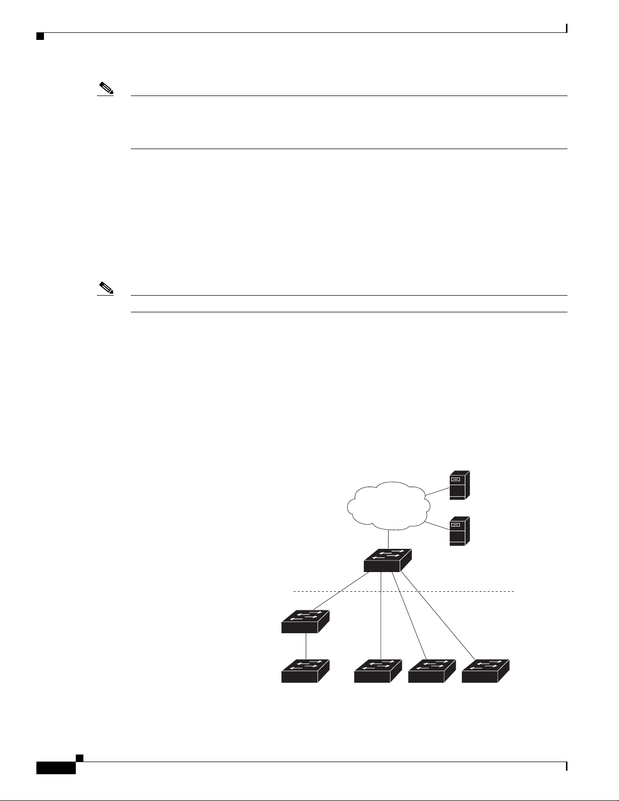
In a typical Smart Install network, a client switch uses DHCP to get an IP address and the director snoops
DHCP messages. For a client to participate in Smart Install zero-touch update, it must use DHCP, and
all DHCP communication must pass through the director so that it can snoop all DHCP packets from
clients. The most automatic operation is when all switches in the Smart Install network use DHCP and
are Smart Install capable. However, any client switch that supports the archive download-sw privileged
EXEC command to download a software image can be used in a zero-touch Smart Install network. Cisco
IOS Release 3.2(0)SE and later, support software install.
Note A Smart Install network can have only one director.
A client switch can participate in Smart Install even if it is not directly connected to the director. The
Smart Install network supports up to seven hops. Intermediate switches or clients connected to the
director through an intermediate switch in a multihop environment can be,
but are not necessarily
Smart Install capable, provided the management VLAN is set to default VLAN 1.
If you use a VLAN other than vlan 1 for management, then the intermediate switch must be Smart Install
capable switch.
Figure 1-1 shows a Smart Install network with external DHCP and TFTP servers. There can be only one
director amongst TFTP servers in any Smart Install network. The director can also serve as the DHCP
and TFTP server.
Figure 1-1 Typical Smart Install Network Diagram
Cisco Smart Install Configuration Guide
1-2
Page 13

Chapter 1 Smart Install Overview
A Smart Install network can be:
• A network where all client switches are of the same product ID (PID), for example,
WS-2960S-48FPS-L. In this case, you can identify a default image and a seed or basic configuration
to use on all client switches.
• A network that includes switches with different PIDs. In these networks, you can configure switch
groups and specify that the same images and seed configuration files are applied to all switches in
the group. A group can be based on a predefined PID, or you can create groups based on product ID,
MAC address, switch stack number, MAC address, or client switch connectivity to a specific
upstream neighbor. When switches in a group are replaced by another switch with the same product
ID, the replacement switch receives the same configuration and image.
After a switch has an image and basic configuration, you can configure specific features on individual
switches and save the configuration to the startup configuration file.
Switches participating in Smart Install zero-touch updates must use DHCP to obtain their IP addresses.
DHCP options are used to send:
• Image filename and location
• TFTP server IP address
• Hostname
Introduction
• Configuration filename
• Director IP address to the other switches
When a director is configured and a client joins the Smart Install network, Smart Install is automatically
enabled on these devices. Beginning with Cisco IOS Release 12.2(58)SE, XE 3.4SG, 15.1(2)SG,
15.1(1)SY, 15.0(2)SE, 3.2(0)SE and later, 3.6.(0)E, or 15.2.(2)E, you can disable Smart Install on a
device and also shut down its Smart Install TCP ports by entering the no vstack global configuration
command on the client or director. When Smart Install is disabled on a device, any Smart Install
configuration on it remains in the running configuration but does not take effect while Smart Install is
disabled. To reenable Smart Install on the device, enter the vstack global configuration command.
These sections include more detailed information on Smart Install components:
• Smart Install Director, page 1-3
• Smart Install Clients, page 1-6
• Smart Install Groups, page 1-9
Smart Install Director
The director in a Smart Install network must be a Layer 3 switch running Cisco IOS Release 12.2(52)SE
or later, XE 3.4SG, 15.1(2)SG, 15.0(2)SE or later, 15.1(1)SY or later, 3.2(0)SE or later, or a router
running Cisco IOS Release 15.1(3)T or later. See Appendix A, “Supported Devices for Smart Install”
for a list of routers and switches that can perform the role of Smart Install director.
Note IE2000 IE3000, and IE3010 support Director with Cisco IOS Release 15.2(2)E.
To configure a device as director, enter the IP address of one of its Layer 3 interfaces in the vstack
director ip_ address global configuration command and enable it as director by entering the vstack
basic command.
Cisco Smart Install Configuration Guide
1-3
Page 14

Introduction
Chapter 1 Smart Install Overview
Note If you have entered the no vstack global configuration command to disable Smart Install on a device,
the vstack director ip_ address and vstack basic global configuration commands are not allowed on the
device. To reenable Smart Install on a device, enter the vstack global configuration command.
When a device is configured as director, The VLAN on which the DHCP snooping is automatically
enabled becomes VLAN 1 by default. The director begins building the director database in VLAN 1. To
specify another VLAN for Smart Install management, you can use the vstack startup-vlan global
configuration command. Depending on the VLAN that is specified in the command, DHCP snooping is
enabled on that VLAN so that the director can identify new switches that are connected to the network,
known as non-VLAN 1 switches.
The database lists the client devices in the Smart Install network and includes this information:
• Type of switch (PID) for all switches, including switches in a stack
• MAC addresses for all switches, including switches in a stack
• IP address of the switch or stack
• Hostname
• Network topology including neighbors interfacing with the switch
• Serial number (only Smart Install capable switches)
Note When the director is a switch, DHCP snooping is enabled on VLAN 1 by default. It is also enabled on
other Smart Install management VLANs that are configured by entering the vstack vlan vlan-range
global configuration command. You can use the vstack startup-vlan global configuration command to
specify another VLAN that should be used for Smart Install management. Cisco IOS Releases
15.1(1)SY, 15.0(2)SE or later, 15.1(2)SG, 3.6.(0)E, 15.2.(2)E, and Cisco IOS XE 3.4SG support
non-VLAN1 management and provide the ability to discover the client switches available on
non-VLAN1.
In a Smart Install network that uses DHCP to assign IP addresses, you only need to configure the
director. Client switches do not require any configuration. Although you can enter command-line
interface commands on clients, configuration commands do not take effect unless the switch assumes the
role of director.
Note You can configure the vstack commands in client mode. but this is effective only when the switch is
converted to a director.
There can be only one director for a set of clients and you cannot configure a backup director. If the
director fails:
• Director database must be rebuilt.
• Any update being performed for a non-Smart Install-capable switch might fail.
• The accumulated download status is lost.
• A configuration backup might not occur before the director restarts.
1-4
The director can change status and become a client switch if:
• The director interface that has the director IP address shuts down.
• The director interface that has the director IP address is deleted.
Cisco Smart Install Configuration Guide
Page 15

Chapter 1 Smart Install Overview
• The director IP address is changed.
If the director becomes a client, DHCP snooping is disabled, and the director database is no longer used.
If the director IP address is provided by DHCP and you configure a different director IP address on a
client switch, the client is longer part of the director’s Smart Install network.
Smart Install relies on a TFTP server to store image and configuration files. The TFTP server can be an
external device, or the director can act as a TFTP server. If the director is the TFTP server, the available
flash file space on the director must be adequate to accommodate the client Cisco IOS image and
configuration files. See the “Configuring the TFTP Server” section on page 2-8.
In a Smart Install network using DHCP, the DHCP server can be an external device or the director can
act as the DHCP server. See the “Configuring the DHCP Server” section on page 2-4. The director
snoops all DHCP packets that pass through it on VLANs that are configured as Smart Install
management VLANs. All network DHCP packets from intermediate or client switches or from an
external DHCP server must pass through the director. The director must be able to snoop all DHCP
packets from clients.
Note Smart Install options in the DCHP offer are option 125, suboption 5 (the image list file), option 125
sub-option 16 (the director IP address), and option 67 (the configuration file).
Introduction
Image List File
Note In Catalyst Switches 3850 and 3650, the image is a bundled with .bin extension.
The director builds a topology director database for the network by collecting information from the
network Smart Install switches. The director uses the database:
• To assign a configuration file and image to a client.
• As a reference to obtain the PID, the image name, and the configuration file for an on-demand
update of network switches.
The director periodically updates the director database based on CDP updates that it receives from
neighbor switches and from Smart Install messages sent to the director by Smart Install capable clients.
The updates contain information about the client neighbors.
An image list identifies the images to be loaded on the client. The image list file is the file that contains
the correct image name for the client. When the director is the TFTP server, this file is stored in flash
memory. Otherwise, it is stored in a remote, third-party TFTP server.
• When the file is stored in the director, the prefix for the image list is flash://, usbflash0://,
bootflash://, bootdisk://, or disk0:// based on the appropriate file systems available on the switch.
• When the file is stored in a remote TFTP server, the prefix is tftp://ip_address/image.tar.
Images must be stored either on the director or on the third-party TFTP server.
For a standalone switch, the image list file contains a single image. For a stack, the image list contains
images for all members of the stack, which could be the same image or different images. For a switch
stack, the director creates the image list file after the user specifies the tar file for each switch in the
stack.
Starting with Cisco IOS Release 12.2(55)SE or later,15.1(1)SY, 15.0(2)SE and later, 3.2(0)SE and later,
XE 3.4SG, 15.1(2)SG, 3.6.(0)E, and 15.2.(2)E, when the user specifies the tar file for each switch, the
director automatically creates the imagelist file.
Cisco Smart Install Configuration Guide
1-5
Page 16

Introduction
Note The upgrade process is initialized even when the imagelist file is copied manually, but the director tries
Configuration Files
Chapter 1 Smart Install Overview
When an external TFTP server is used, the director writes the image list file to the TFTP server. It is
recommended that the TFTP server permit the director to write the image list files to the TFTP Server.
If the director does not have permission to write to the file system of the TFTP server, the director logs
the failure in the system log. You can create the image list files and put them on the TFTP server
manually if the director fails to do so automatically; you cannot fix the issue that prevents the director
from writing to the TFTP server.
to copy the image list file to the TFTP server and the failure system log is displayed periodically.
The director manages these configuration files:
• Startup configuration—The configuration that a client uses when it boots.
• Seed configuration—A configuration on the director that is the basis for the client startup
configuration.
• Backup configuration—An exact copy of a client startup configuration stored in the director.
Smart Install Clients
Client switches have a direct or indirect connection to the director so that they can receive image and
configuration downloads from it. A switch becomes a Smart Install client when either director or when
the director IP address is configured on the switch manually. Client switches use the director database
for image and configuration downloads and receive the image and configuration files from the Smart
Install TFTP server.
A client switch can be an intermediate switch connected to another client switch. A client can be a
standalone switch or a switch stack.
• Director can download images and configuration of clients that are not Smart Install. However, such
clients are entered into the director database only if they are connected to a Smart Install capable
switch. The director can telnet to the client switch and use the archive download-sw privileged
EXEC command to download software to the switch. The director must know the client switch
password to perform the download.
• Smart Install capable switches can communicate directly with the director to update switch
information, can have images and configuration downloaded, and can be managed by the director.
A Smart Install capable client with the director IP address and connectivity to the director sends
switch and neighbor information to the director by using the Smart Install protocol.
Note Switches running Cisco IOS XE Releases 3.2(0)SE and later, 3.6.(0)E, and 15.2.(2)E support software
install.
1-6
All switches in the network with “network” connectivity to the director can be clients, whether or not
they are Smart Install capable. A client switch needs an IP address for management communication and
the director must be able to communicate with that IP address. Client switch IP addresses are assigned
by DHCP or statically configured.
Cisco Smart Install Configuration Guide
Page 17
Chapter 1 Smart Install Overview
Smart Install capable clients send switch and neighbor information to the connected director for the
director database. Client switches that are not Smart Install capable or that are not connected to a Smart
Install capable switch are not entered into the director database. In a multihop topology, for the director
to get the complete topology overview, any client switch upstream of a group of clients must be Smart
Install capable. Clients not in the director database can get an on-demand update, but they cannot get a
zero-touch or group update.
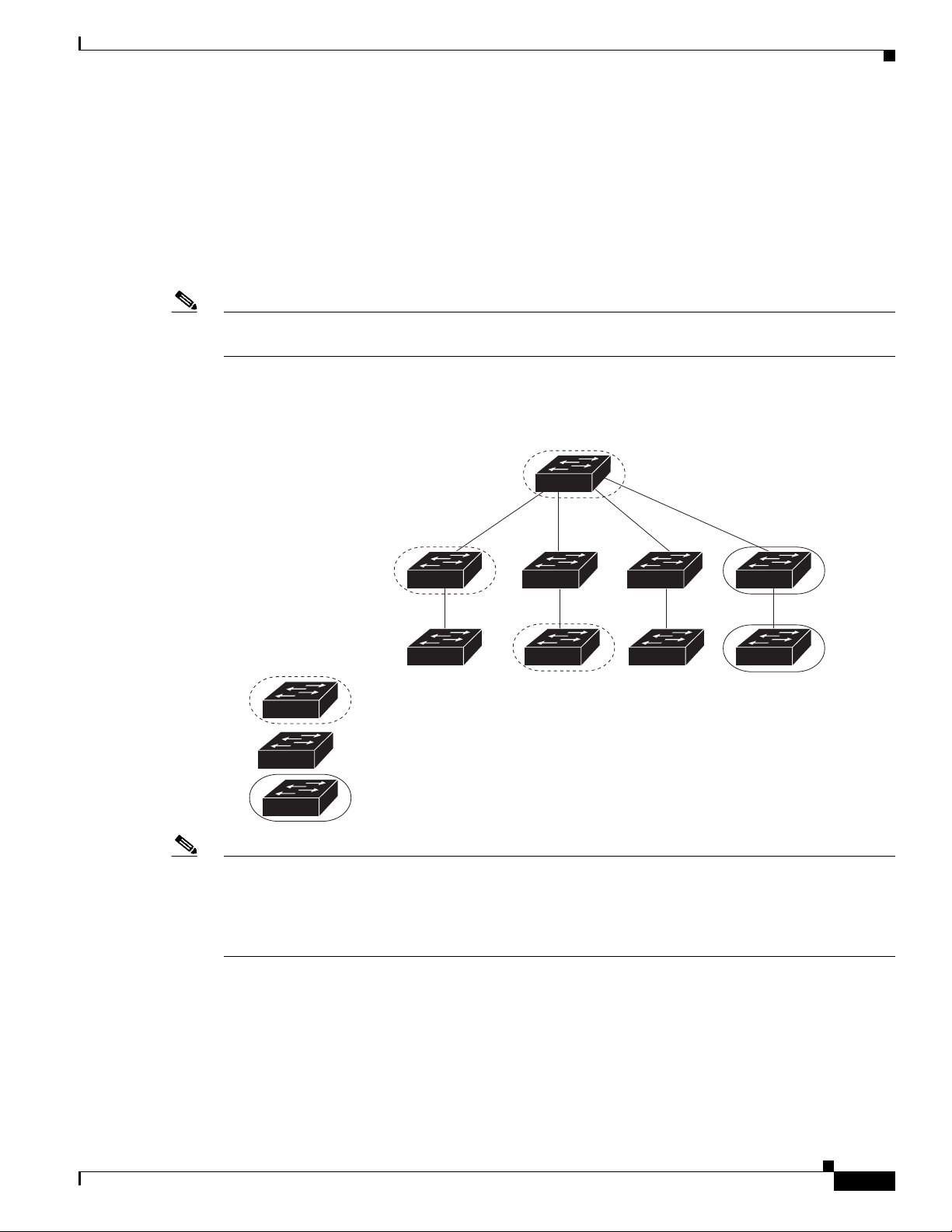
Figure 1-2 shows some possible ways that clients can be interconnected in a network. Tabl e 1-1 and
Table 1 -2 shows the director database knowledge of each client and the type of update that is supported.
Note The topology shown in Figure 1-2 does not represent a typical Smart Install topology but is used to
demonstrate possible types of client interconnections.
Figure 1-2 Possible Interconnections of Smart Install Clients
Introduction
Director
Client 1
Client 2
Smart Install capable switch
Switch running an image earlier than Cisco IOS Release 12.2(52)SE
Smart Install capable switch supporting non-VLAN management
Note The Cisco IOS releases12.2(52)SE or later, XE 3.4SG, 15.1(2)SG, 15.1(1)SY and later, 15.0(2)SE and
Client 3
Client 4
Client 5
Client 6
Client 7
Client 8
276559
later, and 3.2(0)SE and later, support the director role. The Cisco IOS releases 15.0(2)SE, 15.1(1)SY,
15.1(2)SG, XE 3.4SG, 15.0(2)EX, 15.0(2)EX1, 3.6.(0)E, and 15.2.(2)E are Smart Install capable
switches, supporting non-VLAN 1 management and providing the ability to discover the client switches
available on non-VLAN 1.
Table 1 -1 shows the switches that are in the director database and how the director obtained the
information. When a client is a single hop from the director, the client uses CDP to send the director
information about itself. When a client is a Smart Install capable switch, it sends information to the
director about itself and its neighbors.
Cisco Smart Install Configuration Guide
1-7
Page 18

Introduction
Chapter 1 Smart Install Overview
Table 1-1 Director Database Contents of Client Switches
In Director
Client Switch
Client 1 Yes Learned from CDP and from Smart Install. The client also sends
Client 2 Yes Information received from Client 1.
Client 3 Yes Learned from CDP.
Client 4 No No information available. The client is not an immediate neighbor
Client 5 Yes Learned from CDP.
Client 6 No No information available. The client is not an immediate neighbor
Client 7 Yes Learned from CDP and from Smart Install. The client also sends
Client 8 Yes The information to Client 8 will be sent by Client 7 via
Database? Source of Database Information
information about its neighbor (Client 2).
of the director or another Smart Install switch.
of the director or another Smart Install switch.
information about its neighbor Client 8. Client 7 is a non-VLAN 1
switch.
non-VLAN1. Client 8 is a non-VLAN 1 switch.
Table 1 -2 shows the director database knowledge of each client and the type of update that is supported
in various software versions. For information about Smart Install supported switches, routers, and
minimum software releases for directors and clients, see Supported Devices for Smart Install.
Table 1-2 Types of Updates Supported by Each Client
Device Software Version
Zero-Touch
Update
On-Demand
Update of Client
On-Demand Update of
Group
Client 1 12.2(52)SE or later Yes Yes Yes
Client 2 Earlier than 12.2(52)SE Yes Yes Yes
Client 3 Earlier than 12.2(52)SE Yes Yes Yes
Client 4 12.2(52)SE or later Yes Yes Yes
Client 5 Earlier than 12.2(52)SE Yes Yes Yes
Client 6 Earlier than 12.2(52)SE Yes Yes No. Switch not in
director database.
Client 7 15.0(2)SE, 15.1(1)SY,
Ye s Ye s Ye s
15.1(2)SG, XE 3.4SG,
15.0(2)EX, 15.0(2)EX1,
3.6.(0)E, and 15.2.(2)E
Client 8 15.0(2)SE,15.1(1)SY,
Ye s Ye s Ye s
15.1(2)SG, XE 3.4SG,
15.0(2)EX, 15.0(2)EX1,
3.6.(0)E, and 15.2.(2)E
1-8
To see the types of Smart Install clients in a network, enter the show vstack status privileged EXEC
command.
Cisco Smart Install Configuration Guide
Page 19

Chapter 1 Smart Install Overview
Director# show vstack status
SmartInstall: ENABLED
Status: Device_type Health_status Join-window_status Upgrade_status
Device_type: S - Smart install N - Non smart install P - Pending
Health_status: A - Active I - Inactive
Join-window_Status: a - Allowed h - On-hold d - Denied
Image Upgrade: i - in progress I - done X - failed
Config Upgrade: c - in progress C - done x - failed
Director Database:
DevNo MAC Address Product-ID IP_addr Hostname Status
===== ============== ================= =============== ========== =========
0 0018.7363.4200 WS-C3750-24TS 172.20.249.54 IBD-MXD-ST Director
1 0016.4779.b780 WS-C3750G-24TS 172.20.249.54 IBD-MXD-ST Director
2 d0d0.fd37.5a80 WS-C3750X-48P 172.20.249.54 IBD-MXD-ST Director
3 0026.5285.7380 WS-C3750E-24TD 172.20.249.54 IBD-MXD-ST Director
4 0024.13c6.b580 WS-C3750E-24TD 172.20.249.115 DEV-c6.b5c S A a
5 0021.a1ab.9b80 WS-C2960-48TC-S 172.20.249.249 DEV-ab.9bc S A a I C
6 0024.5111.0900 WS-C3750E-24TD 172.20.249.222 DEV-11.094 S A a I C
7 001d.45f3.f600 WS-C3750G-24TS 172.20.249.87 DEV-90.f64 S A a
8 0016.c890.f600 WS-C3750G-24TS 172.20.249.87 DEV-90.f64 S A a
9 001f.2604.8980 WS-C2960-48TC-S 172.20.249.89 DEV-04.89c S A a I C
10 001b.d576.2500 WS-C3750E-24PD 172.20.249.91 DEV-a6.1cc S A a I C
These fields were added in Cisco IOS Release 12.2(58)SE or 15.1(1)SY to provide more information
about each client:
Introduction
• Device type: S (Smart Install capable, running Cisco IOS Release 12.2(52)SE or later, 15.1(1)SY,
15.0(2)SE and later, 3.2(0)SE and later), 3.6.(0)E, or 15.2.(2)E, N (not a Smart Install device), or P
(pending, unable to determine).
• Device health status: Active (the director is receiving periodic updates from the device) or Inactive
(the device is disconnected or has not provided updates for three consecutive keepalive periods)
• Join window status: a (allowed), h (on hold), or d (denied). See the “Using a Join Window” section
on page 1-13.
• Upgrade status: An image update is i (in progress), I (complete), or X (failed). A configuration
upgrade is c (in progress), C (complete), or x (failed).
Smart Install Groups
When all switches in a Smart Install network have the same PID, they can run the same image and the
same seed (basic) configuration file. In this case, you can assign a default image and configuration file
for all clients. However, if there is more than one PID in the network or if you want a different
configuration file to run on some switches, depending on their function in the network, you should
configure Smart Install groups and assign an image and configuration file for each group.
• Custom groups take precedence over built-in groups and are based on:
–
–
Stack group—For switches in a stack, you can configure groups based on their number in the
stack. Stack groups are used only for switch stack upgrades, and clients do not need to be in the
director database. Starting with Cisco IOS Release 12.2(58)SE, 15.1(1)SY, 15.0(2)SE and later,
3.2(0)SE and later, 3.6.(0)E, and 15.2.(2)E if a stack is homogeneous (all one switch type), you
do not need to identify each switch type.
MAC address—You can create a custom group of specific switches by using the MAC addresses
of the switches to configure the group. You can include switches with the same or different
product IDs, as long as they use the same image and configuration file. Enter the show vstack
neighbors all privileged EXEC command to see the MAC addresses of switches in the Smart
Install network.
Cisco Smart Install Configuration Guide
1-9
Page 20

DHCP and Smart Install
Chapter 1 Smart Install Overview
–
Connectivity—You can configure a custom group based on network topology; that is, all
switches that have the same upstream neighbor. Connectivity groups take precedence over
groups with matching product IDs or stack numbers. Connectivity groups include only
standalone switches (not switch stacks), and clients must be in the director database.
–
Product IDs (PIDs)—These product IDs are all supported models, including newer PIDs that
were not shipping when the software was released and therefore are not in the CLI. PID groups
include only standalone switches (not switch stacks), and clients do not need to be in the
director database.
The priority of custom groups from high to low is stack group, MAC address, connectivity, and
product ID.
• Built-in groups are based on PIDs that you can select from the CLI. These represent the fixed
Ethernet switching products that were shipping when the software was released, for example, 3750,
3560, 2975, 2960, 3850, and 3650.
Switches that belong to a group use the image and configuration file assigned to that group. If a client
switch does not belong to a group in the director database, it is assigned the default image and
configuration file.
Note If there is more than one switch PID in the network, we recommend configuring built-in or custom
groups. The default image and configuration is used in networks with only one product ID.
An example of the use of custom groups is a network where all client switches are the same PID, but one
requires a different configuration. For example, a retail store might have checkout counters and a
pharmacy, and the pharmacy switch requires a different configuration. The checkout counters would use
the default configuration, but you would create a custom group for the pharmacy.
DHCP and Smart Install
DHCP is recommended in Smart Install networks and is required for zero-touch updates. On-demand
updates do not require DHCP. In a DHCP network, DHCP snooping is automatically enabled on the
director. The director snoops DHCP offers and requests to and from the client switches and uses DHCP
snooping to insert the DHCP options used in the Smart Install operation.
However, because DHCP snooping is not supported on routed ports, you should not connect routed ports
directly to the client or the director.
A DHCP server in a Smart Install network can be positioned in one of these ways:
• The Smart Install director can act as the DHCP server in the network. When the DHCP offer goes
to the client switches, the director allocates the IP addresses and assigns configurations and images
and the hostname as DHCP options in the DHCP offer and DHCP acknowledgment. DHCP snooping
is automatically turned on for the director.
• The DHCP server can be another device (third-party server) in the Smart Install network. In this
case, DHCP packets between the clients and DHCP server must pass through the director.
1-10
Note You can configure a join-window time period so that the director can only modify the DHCP
offer and send the image and configuration files to the client during the configured window. The
join window restricts Smart Install for a specified period of time and acts as a security precaution
to control when a client can receive these files. See the “Using a Join Window” section on
page 1-13.
Cisco Smart Install Configuration Guide
Page 21

Chapter 1 Smart Install Overview
• A third-party server and the director DHCP server can coexist in a network. In this case, the director
is responsible only for the DHCP requests of the switches in the Smart Install network. The director
maintains the Smart Install database and pool; other DHCP database functions are maintained by the
third-party server.
See the “Configuring the DHCP Server” section on page 2-4 for configuration instructions.
If the Smart Install DHCP server is the director or another device running Cisco IOS and the network
reloads, the server might assign new IP addresses to participating switches. If a switch IP address
changes, it might no longer be reachable. If the director IP address changes, it is no longer the Smart
Install director, which could break the director and client switch relationships. This is an unlikely but
possible corner-case occurrence. To prevent this occurrence, you should enable DHCP remembering by
entering the ip dhcp remember global configuration command or the remember DHCP-pool
configuration command on the DHCP server,
Non-Cisco IOS third-party DHCP servers require an IP-address-to-MAC-address binding to ensure that
the same IP address is given to a switch on a reload.
Note In Smart Install networks that do not use DHCP, you must manually configure the director IP address on
each client switch by entering the vstack director ip-address global configuration command. Client
switches require only the director IP address. Smart Install networks that do not use DHCP cannot
support zero-touch updates but can support on-demand update.
Adding a Client Switch to the Network
Adding a Client Switch to the Network
When a switch arrives from the factory, it contains the factory default image. When it is plugged in and
connected to the network and boots up, it tries to get its IP address from DHCP. When a device is added
to the network, a notification is sent to the director that a new client has joined. If the switch is connected
(directly or indirectly) to the Smart Install director, the director recognizes the new switch through
DHCP offers and acknowledgments. The director searches its database to determine if the switch
belongs to a configured group. If not, the director determines if the switch matches the Smart Install
network default PID. If the director has a configuration for the type of client that was added and if the
join window is open, the new client receives the image and configuration files.
Note When clients in a Smart Install network consist of more than one PID, you should configure built-in
groups or custom groups based on MAC address, connectivity, stack group, or product-ID, and define
the image and configuration files for each group.
If the DHCP Server is external or internal (running on the director), the director inserts options into the
DHCP response, informing the client where to download its IOS image and configuration file provided
the join window is open.
Note If a join window has been configured, the Smart Install configuration and image files are sent to the client
only during the configured time period. A client switch sends an error message if it cannot download an
image or configuration file due to misconfiguration, if the image or configuration file is not available, or
if a join window is configured and the DHCP acknowledgments occurs beyond the configured time
frame. See the “Using a Join Window” section on page 1-13 for more information.
Cisco Smart Install Configuration Guide
1-11
Page 22

Backing Up the Client Configuration
After a switch has been added to the Smart Install network, you can do an on-demand download of an
image or configuration file to the client at any time if the switch meets these criteria:
• A switch that is not Smart Install capable must have an enable mode password and a valid IP
interface.
• A switch running the Smart Install image must have a valid IP interface.
If a client switch in the Smart-Install network is running Cisco IOS Release 12.2(55)SE or later, or
3.2(0)SE and later, 15.0(2)EX, 15.0(2)EX1, 3.6.(0)E, and 15.2.(2)E is replaced with a switch with the
same product ID, the new client receives the same image and configuration as the replaced client. Se the
“Replacing a Client Switch” section on page 1-12.
See Chapter 2, “Configuring Cisco Smart Install Devices” for typical configurations.
Backing Up the Client Configuration
After a client boots up, it sends a copy of its startup configuration to the director. This file is the backup
configuration for that client. Any time the user, directly or through the director, saves a client
configuration, a backup configuration is created. The configuration is stored on the local repository on
the director or on a remote repository on a server. The backup file is used to reconfigure a client during
a zero-touch replacement.
Chapter 1 Smart Install Overview
Note Client backup is supported only when the director and client are running Cisco IOS Release 12.2(55)SE
or later.
Client configuration backup is enabled by default. You can disable it by entering the no vstack backup
global configuration command. You enable the file backup feature on the director by entering the vstack
backup and you can configure a repository for the backup files. If you do not specify a repository, the
files are stored in the director flash:/vstack directory.
A client configuration backup is triggered:
• When the write memory privileged EXEC command is entered on the client.
• When the director boots up, it requests configuration information from clients and backs up these
configurations.
Replacing a Client Switch
You can use zero-touch replacement to exchange and install a like-type client in the Smart Install
network. When a new switch is added to the network, a CDP database update is sent to the director,
which determines if this is a new MAC address and therefore a new client. When a client needs to be
replaced and is removed from the network, the CDP database lists the removed client as inactive. If
another client MAC address with the same product-ID is detected on the same port, this client is
considered a replacement client. The director gives it the same image and configuration that the previous
client had.
The director removes the entry for the replaced client from the director database. If the replaced client
is put elsewhere in the network, the director creates a new entry for it that includes the client’s new
information.
1-12
Cisco Smart Install Configuration Guide
Page 23

Chapter 1 Smart Install Overview
During a zero-touch replacement, the replacement client receives the last backed-up configuration file,
which is stored in the director or a remote repository. Client configuration files are backed up by default,
unless you disable this functionality on the director.
Only one Smart Install client can be replaced at a time on the same branch and only if there is one path
to the director.
Note Zero-touch replacement is supported only when the director and the replaced client are running Cisco
IOS Release 12.2(55)SE or later, 15.1(1)SY, 15.0(2)SE and later, 3.2(0)SE and later, 15.0(2)EX,
15.0(2)EX1, 3.6.(0)E, or 15.2.(2)E. When a client switch running an earlier release is replaced, the new
switch receives a seed replacement.
When the replacement client and existing client do not have the same product ID, port connections, or
interfaces, the replacement client is considered new to the Smart Install network. For example, a
replacement client must be connected to the same ports on the director and on other client switches as
was the original client. When a new device is added to the network, a notification is sent to the director
that a new client has joined. If the director has a configuration for the type of client that was added and
if the join window is open, the new client receives the image and configuration files.
Replacing a Client Switch
Using a Join Window
A join window is a time window during which the client can update image or configuration files. The
director can provide information about the image and configuration to the client only during this
window. A client attempting to join the Smart Install network outside the join window is not allowed to
do so and cannot update the image and configuration files.
Use the vstack join-window mode auto global configuration command to automatically update clients
with the latest image and configuration files when they are added during a join window. Use the no
vstack join-window mode global configuration command to put the client in a hold state.
Use the following commands to open or close a join window:
• Enter the vstack join-window start [date] hh:mm [interval] [end date] [recurring] global
configuration command to configure a time window to control downloads of configuration and
image files to client switches.
• Enter the vstack join-window close global configuration command to manually close a join
window, enter the no vstack join-window close global configuration command to manually open a
join window.
Note You cannot combine the vstack join-window start and [no] vstack join-window commands to close
and open the join window.
If a join window is configured, a zero touch update is possible only during the configured window. If a
switch connects to the director at any time other than during the join window, the Smart Install
configuration and image files are not automatically downloaded. Instead, the new switch receives the
default files from the DHCP server. This feature provides control of the files and prevents unauthorized
switches from receiving the Smart Install configuration.
If a join window is not configured, a zero touch update can happen at any time because that is the default
state.
When a join window is configured, and the DHCP acknowledgement occurs outside of the configured
window, a client switch sends an error message that it cannot download an image or configuration file.
Cisco Smart Install Configuration Guide
1-13
Page 24

Replacing a Client Switch
Configuring Join Window Mode
The join window mode includes a hold state that adds an extra level of security for the client. The hold
state lets you control whether or not the client can receive a software upgrade, and how the upgrade is
performed. The hold-state is either on or off when the join window is active.
You configure automatic join window mode with the vstack join-window mode auto global
configuration command. In this mode, when a client joins the network, the director automatically
upgrades it when the join window is open.
When you set the mode to manual by entering the no vstack join-window mode global configuration
command, when a client joins the network during an open join window, the client is put on the hold list.
You can review clients on the hold list by entering the show vstack status user EXEC command. You
can remove a client from the hold list by entering the vstack on-hold-clients remove global
configuration command.
Note When a client has been removed from the hold state to allow that client to join the network, you must
restart the client to again put it in the hold state (if the mode is manual) or to automatically upgrade if
the mode is auto and the join window is open.
Chapter 1 Smart Install Overview
When a new client joins the network and the mode is set to auto, the join window state is active, whether
or not the join window is open or closed. When the mode is set to manual and the join window is open,
the client is put on the hold list. If the join window is closed, the client cannot join the network (denied).
Table 1 -3 lists the join window states and the actions that are allowed or not allowed for each state.
Table 1-3 Join Window States and Functionality
Join Window State Zero-Touch Updates On-Demand Updates Configuration Backup
Active Allowed Allowed Allowed
Deny Not allowed Allowed Allowed
Hold Allowed with user
Allowed Not allowed
intervention
Starting with Cisco IOS Release 12.2(58)SE,15.1(1)SY, 15.0(2)SE and later, 3.2(0)SE and later,
3.6.(0)E, and 15.2.(2)E, you can manually change the join window state for a client or multiple clients
from the denied state to the active or held state by using the vstack join-window-status index client-id
{allowed | held} privileged EXEC command.
1-14
Cisco Smart Install Configuration Guide
Page 25

Chapter 1 Smart Install Overview
Updating Client Switches
Supported types of image and configuration updates:
• Zero-touch update—For a client with no configuration. This could be for the initial installation of
an image and configuration on a new client, for image and configuration installation on a client after
a write erase and reload, or, in case of a replacement switch, if vstack backup is enabled. The
Smart Install network must run DHCP to perform zero-touch updates.
On all clients, prior to Cisco IOS Release XE 3.5.0E and Cisco IOS 15.2(1)SG, only image+config
zero-touch upgrades were supported. With Cisco IOS Release XE 3.6.0E and Cisco IOS Release
15.2(1)SG, image+config zero-touch upgrade are no longer mandatory; zero-touch config alone and
zero-touch image alone upgrades are now supported on all clients.
• On-demand update—For clients that are already in the network and connected to the director.
On-demand updates can be performed on single client or on all clients that belong to a built-in group.
DHCP is not required for on-demand updates. The director needs the IP address of a client for a
single-client update if the client is not in a built-in group. For an on-demand update of a client
running an image earlier than 12.2(52)SE, the client must have an enable password and an IP
interface configured.
You can do zero-touch or on-demand updates to any Smart Install client switches. You can also use the
vstack download-image and vstack download-config privileged EXEC commands from the director to
update the image or configuration of any switch as long as the director has a connection (directly or
through another switch) to the switch. You can also telnet to a client switch and use the archive
download-sw privileged EXEC command to update switch software. When you telnet to a client switch,
you must know the switch enable passwords to do any configuration.
Beginning with Cisco IOS Release 12.2(58)SE, 15.1(1)SY, 15.0(2)SE, 3.2(0)SE and later, 3.6.(0)E, you
can perform a simultaneous update of multiple clients that have the same product ID and password by
entering the index numbers from the director database in the vstack download-image privileged EXEC
command.
Updating Client Switches
Zero-Touch Installation
A zero-touch installation is an update initiated by the director on a client switch that has no
configuration. You can perform a zero-touch installation on Smart Install capable switches and
non-Smart Install switches. The zero-touch installation occurs automatically with little or no
intervention. A switch with no configuration can be a new, out-of-box switch or one on which you have
entered the write erase and reload privileged EXEC commands.
During a zero-touch installation, do not touch the console keyboard or attempt to enter a command or
auto return on the switch. Else, the auto install and Smart Install processes stop. To recover and restart
the process, you need to return to the system prompt, enter write erase and reload commands, and
restart the process.
If the TFTP server is the director, the file is saved in the director root directory. If the server is another
device, it is saved in the tftproot directory. This is the default directory in the TFTP server where the files
to be sent using TFTP are stored. The imageclist file, the new configuration file, and the image are also
stored in this directory.
See the “Configuring the TFTP Server” section on page 2-8.
Cisco Smart Install Configuration Guide
1-15
Page 26

Connecting to a Client Switch
Connecting to a Client Switch
To connect to the client switch command-line interface, enter the vstack attach {client-index |
client_ip_address} privileged EXEC command. The client-index number represents active clients in the
Smart Install network, displayed in the command-line help by entering a question mark (?) after the
vstack attach command. The same client number is valid until the client reboots.
Director# vstack attach ?
1 c3750-2042 @ IP 10.0.0.1 : MAC 0000.0040.4080
2 c3750-2045 @ IP 10.0.0.2 : MAC 0000.000c.0d80
A.B.C.D IP address of remote node to attempt attaching to
To attach to a client, the client switch must be configured for telnet service and have a configured enable
password.
Chapter 1 Smart Install Overview
1-16
Cisco Smart Install Configuration Guide
Page 27

CHA PTER
2
Configuring Cisco Smart Install Devices
This section includes some basic scenarios and tasks that you might configure in a Smart Install network.
• Configuration Guidelines and Recommendations, page 2-1
• Configuring the DHCP Server, page 2-4
• Configuring the TFTP Server, page 2-8
• Establishing a Remote Client Session, page 2-8
• Configuring a Network with Single or Mixed Switch Types, page 2-9
• Updating On-Demand to a New Image or Configuration, page 2-16
• Using Custom Groups to Configure Groups Based on Connectivity, MAC Address, Stack Number,
or Product ID, page 2-18
• Managing Client Configuration Files, page 2-28
• Other Configuration Options, page 2-29
• Smart Install Configuration Examples, page 2-42
Configuration Guidelines and Recommendations
• If the startup configuration fails to download, the client can go into an infinite loop because there is
no startup configuration to update. The only way to recover from the loop is to press Enter when
the client is coming up after a reload so that the update process stops.
• When performing a zero-touch update, you should always update both the image and the startup
configuration files. To update only the image or only the configuration file, use the vstack
download-image or vstack download-config privileged EXEC commands for an on-demand
download instead.
• To update only the image or only the configuration file, use the vstack download-image or vstack
download-config privileged EXEC commands for an on-demand download instead.
• On the Catalyst 3750 and Catalyst 4500 series switches, beginning with Cisco Release IOS XE
3.6.(0)E, and Cisco Release IOS 15.2(1)SG,15. 0(2)SE, and 15.2.(2)E, the following combinations
of zero-touch upgrade are supported
–
Image and configuration zero-touch upgrade—User specifies both image and configuration on
the director.
–
Configuration-only zero-touch upgrade—User specifies configuration alone on the director.
–
Image-only zero-touch upgrade—User specifies image alone on the director.
Cisco Smart Install Configuration Guide
OL-28027-01
2-1
Page 28

Configuration Guidelines and Recommendations
• On the Catalyst 4500 series switch director and client functionality is supported; beginning with
Cisco IOS Release IOS XE 3.6.(0)E the above mentioned combinations of zero-touch upgrade can
be configured on the director or client.
• For the above features to work on the client side, the clients must be running the image with Cisco
Release IOS 15.2(1)SG or higher.
Note For an on-demand download, update the image and configuration on the client with the vstack
download-image or vstack download-config commands.
If you trigger a zero-touch upgrade with backup enabled and Rev2 (such as, backed-up
configuration) accessible on the SMI director, the Rev2 is sent for an upgrade. If you accidentally
delete the Rev2 file, the zero-touch upgrade fails because the backup configuration is missing.
However, the client attempts another reload and boots with the seed (default) configuration, ensuring
a smoothly functioning zero-touch upgrade irrespective of the missing backup configuration.
If backup is enabled and an image-only upgrade is specified on the director, the client boots up with
the backed-up configuration and the image specified when the upgrade launches on the client.
However, if backup is disabled, the client boots with the image [alone] specified on the director for
that client.
Chapter 2 Configuring Cisco Smart Install Devices
• Switches are updated one hop at a time. The director cannot update switches in hop 2 while it is
upgrading switches in hop 1.
• Because DHCP snooping is not supported on routed ports, you should not connect routed ports
directly to the client or the director. Without DHCP snooping, the director will not detect a DHCP
request from the client, which prevents Smart Install from working on that client. Routed ports
cannot participate in Smart Install.
• For client switches with only 16 Mb of flash memory, before upgrading the Cisco IOS image, ensure
that there is enough free flash space available to download a new image and delete unnecessary files.
The configuration file might not be necessary because Smart Install can provide the configuration
file when the client boots up.
• In Catalyst 6500 Supervisor Engine 2T switches, flash size supports onboard and external disks to
download the image and the configuration file.
• The director can act as the TFTP server, eliminating the need for an external TFTP serving device.
Follow these guidelines when configuring the director as TFTP server:
–
The total flash space (used and free) on the director must be large enough to contain the director
image and configuration file and the image and configuration files required for client switches.
–
There must be enough available flash on the director to hold the client Cisco IOS images and
configuration files. The Cisco IOS image files vary in size, depending on the client switch
product IDs and whether or not crypto images are being installed.
–
When the director is the TFTP server, a copy of the configuration file for each client switch is
stored in the root directory of the flash file system on the director. There must be enough space
for each planned client group.
2-2
–
Most director switches have enough flash memory to hold one client Cisco IOS image and a
small number of client configuration files. For example, the Catalyst 3750 switch can have a
maximum flash size of 64 MB, which accommodates only 4 or 5 images, based on the image
size.
–
If the Smart Install network includes client switches with more than one product ID, you should
use an external TFTP server.
Cisco Smart Install Configuration Guide
OL-28027-01
Page 29

Chapter 2 Configuring Cisco Smart Install Devices
–
When the director is the TFTP server, downloading a TFTP file will be slower than the external
TFTP server. If downloading the TFTP file is a priority, use an external TFTP server, especially
if there are multiple clients performing TFTP downloads simultaneously.
• If the TFTP server is a third-party (non-Cisco) device, you should disable the server option to
change the name of a file if another file is created with the same name. Otherwise, duplicate
imagelist files might be created.
• Client switches can be on any VLANs other than the default if the director is configured to snoop
on that VLAN (enter the vstack vlan vlan-id global configuration command) and if traffic from the
VLAN flows through the director.
–
The director can snoop on multiple VLANs extending to clients on different Layer 2 subnets.
–
Client switches can be on different routed subnets as long as there are routes between the
director and the subnet. In these cases, a relay agent between a client and director is required
for Smart Install downloads.
–
Smart Install does not function if the client is connected directly to a routed port on the director.
• Stacking considerations:
–
If the director is in a switch stack and a master switchover occurs when a non-Smart Install
client switch is being updated, the client switch update is not completed.
Configuration Guidelines and Recommendations
–
If the client switch is a stack and not all members are up and operational, downloading of new
images to the stack members fails.
–
Upgrading a stack requires configuring a custom group matching the stack group.
–
When a stack is upgraded, you should restart all stack members at the same time.
–
When a stack is deliberately partitioned, the new stacks should have the required configuration
for upgrades, that is, the stack group members must be configured correctly.
• For Catalyst 3750-X, 3750-E, 3650-X, and 3650-E client switches, install the appropriate license
files before updating the image. Smart Install does not apply to image licensing.
• To disable Smart Install on a director or client, enter the no vstack global configuration command
on the device. Enter the show vstack status privileged EXEC command to see if Smart Install is
enabled or disabled on a device.
• Client switches with static IP addresses cannot get zero-touch downloads but can receive on-demand
downloads.
• If the director temporarily loses communication with the client switches, there is no impact to the
Smart Install feature unless the client is in the middle of installing Cisco IOS images or downloading
the configuration. If this happens, manual intervention might be required to restart the process.
• We recommend that configuration files do not include boot host dhcp. If a configuration file does
include this configuration, do not apply the configuration file to switches with interfaces that do not
have a configured IP address.
• When a director is configured and a client joins the Smart Install network, Smart Install is
automatically enabled on these devices. Beginning with Cisco IOS Release 12.2(58)SE, 15.1(1)SY,
15.0(2)SE and later, and 3.2(0)SE and later, you can disable Smart Install on a device and also shut
down its Smart Install TCP ports by entering the no vstack global configuration command on the
client or director.
–
When Smart Install is disabled on a device, any Smart Install configuration on the device
remains in the running configuration but does not take effect while Smart Install is disabled.
OL-28027-01
–
When Smart Install is disabled on a device, the vstack director ip_ address and vstack basic
global configuration commands are not allowed.
Cisco Smart Install Configuration Guide
2-3
Page 30

Configuring the DHCP Server
• Image-only or configuration-only upgrades cannot be performed on IBCs running an image prior to
Most configuration commands are visible and can be entered on the director or on a client, but only the
ones configured on the director take effect. If you enter commands on a client switch, they do not take
effect now, but if the client later becomes the director, the commands are then valid.
Chapter 2 Configuring Cisco Smart Install Devices
–
If you disable Smart Install on the director and there were Smart Install DHCP IP addresses
configured, you need to manually unconfigure them.
–
To re-enable Smart Install on the device, enter the vstack global configuration command.
Cisco IOS Release XE 3.6.0E. If an IBD is configured for an image-only or configuration-only
upgrade but the IBC does not support an upgrade, the following cases apply:
–
The Director is configured to perform an image-only upgrade for the client.
Prior to Cisco IOS Release XE 3.6.0E, IBC did not receive the configuration path and the
configuration-only upgrade failed, but the image upgrade proceeded and IBC reloaded.
Although the image upgrades, Cisco does not claim this process to be “Image-only” because
IBC tries to download the configuration file and fails, displaying error messages.
–
The Director is configured to perform a configuration-only upgrade for the client.
Prior to Cisco IOS Release XE 3.6.0E, the configuration upgrade proceeded but IBC did not
receive the image path, hence the image upgrade failed, and IBC did not reload.
DHCP Configuration Guidelines
• Although we recommend that the director be configured to act as DHCP server for the clients, Smart
Install can also use an external DHCP server. If you use an external device as DHCP server, you
could configure the DHCP server to send option 125/sub-option 16 for the director IP address to
avoid the possibility of fake DHCP servers.
• We recommend configuring a Cisco IOS DHCP server to remember IP bindings to ensure that
devices in the Smart Install network retain the same IP address in the event of a network or device
reload.
• In networks that do not use DHCP to assign IP addresses to the clients, you must configure the IP
address of the director on each client switch.
• In a Smart Install network, we recommend not to configure DHCP snooping and DHCP relay on the
same interface of the switch.
Configuring the DHCP Server
To perform zero-touch updates, the Smart Install network must be running DHCP. The DHCP server
might be the director, another Cisco device running Cisco IOS, or a non-Cisco third-party server. You
can also have the director act as the Smart Install DHCP server and have another device perform all other
DHCP server functions.
Use one of the following procedures to set up a Cisco device as DHCP server, or if you choose to
configure a non-Cisco third-party device as DHCP server, follow the instructions in the product
documentation for configuring a network address and a TFTP server.
2-4
Note You should not configure any client switches participating in Smart Install as the DHCP server.
Cisco Smart Install Configuration Guide
OL-28027-01
Page 31

Chapter 2 Configuring Cisco Smart Install Devices
• Configuring the Director as the DHCP Server, page 2-5
• Configuring Another Device as DHCP Server, page 2-6
Note If the DHCP server is the director or another Cisco IOS device and the network reloads, it is
possible that DHCP could assign new IP addresses to the devices. This is an unlikely occurrence,
but if it does happen, you might need to reassociate the director and client switches by manually
entering the director IP address on the director or the client switches. To prevent this occurrence,
configure the DHCP server to remember the IP bindings by entering the ip dhcp remember
global configuration command or the remember DHCP pool configuration command.
Configuring the Director as the DHCP Server
You can configure the director as DHCP server and create DHCP server pools directly from the Smart
Install director.
Beginning in privileged EXEC mode, follow these steps on the director to configure it as the DHCP
server:
Configuring the DHCP Server
Step 1
Step 2
Step 3
Step 4
Step 5
Step 6
Step 7
Step 8
Step 9
Command Purpose
config terminal Enters global configuration mode.
vstack director ip_ address Configures the device as the Smart Install director by entering
the IP address of an interface on the device.
vstack basic Enables the device as the Smart Install director.
vstack startup-vlan vlan_value Specifies the default VLAN that the director should use for
Smart Install management.
vstack dhcp-localserver poolname Creates a name for the Smart Install DHCP server address
pool, and enter vstack DHCP pool configuration mode.
address-pool network-number mask
prefix-length
Specifies the subnet network number and mask of the DHCP
address pool.
Note The prefix length specifies the number of bits that
comprise the address prefix. The prefix is an
alternative way of specifying the network mask of the
client. The prefix length must be preceded by a
forward slash (/).
default-router ip_address Specifies the IP address of the DHCP default router for the
pool.
Note You can use the vstack startup-vlan global
configuration command to specify another VLAN that
should be used for Smart Install management.
file-server address Specifies the IP address of the TFTP server.
Note If the director is also the TFTP server, you must enable
it. See the “Configuring the TFTP Server” section on
page 2-8.
exit Returns to global configuration mode.
OL-28027-01
Cisco Smart Install Configuration Guide
2-5
Page 32

Configuring the DHCP Server
Command Purpose
Step 10
Step 11
Step 12
Step 13
ip dhcp remember (Optional) Configures the DHCP server to remember the IP
end Returns to privileged EXEC mode.
copy running-config startup config (Optional) Saves your entries in the configuration file.
show dhcp server Verifies the configuration by displaying the DHCP servers
Chapter 2 Configuring Cisco Smart Install Devices
bindings of a device. If the network or device reloads, the
DHCP server issues the same IP address to a client that it had
before the reload. This command is supported in Cisco IOS
Release 12.2(53) or later on switches and in Cisco IOS
Release 15.1(3)T or later on routers.
recognized by the device.
This example shows how to configure the Smart Install director as the DHCP server:
Director# configure terminal
Director(config)# vstack director 1.1.1.20
Director(config)# vstack basic
Director(config)# vstack dhcp-localserver pool1
Director(config-vstack-dhcp)# address-pool 1.1.1.0 255.255.255.0
Director(config-vstack-dhcp)# default-router 1.1.1.30
Director(config-vstack-dhcp)# file-server 1.1.1.40
Director(config-vstack-dhcp)# exit
Director(config)# ip dhcp remember
Director(config)# end
DHCP snooping is automatically enabled on the director. Therefore, you do not need to enable it when
the director is the DHCP server.
Configuring Another Device as DHCP Server
If the Smart Install director is not the DHCP server, you can use the traditional Cisco IOS DHCP
commands to configure a server pool outside the Smart Install network. The director must have
connectivity to the DHCP server. For procedures to configure other DHCP server options, see the
“Configuring DHCP” section of the “IP Addressing Services” section of the Cisco IOS IP Configuration
Guide, Release 12.2 or the “IP Addressing Services” section of the Cisco IOS IP Configuration Guide,
Release 15.1 from Cisco.com. This procedure shows the minimum steps that you need to perform to
configure a DHCP server.
Note Do not configure a client switch as DHCP server. If you configure DHCP server commands on a client
switch, the switch will assign IP addresses, and will not be able to use Smart Install.
Beginning in privileged EXEC mode, follow these steps:
Command Purpose
Step 1
Step 2
Step 3
config terminal Enters global configuration mode.
ip dhcp pool poolname Creates a name for the DHCP server address pool, and
enters DHCP pool configuration mode.
bootfile filename Specifies the name of the configuration file to be used.
2-6
Cisco Smart Install Configuration Guide
OL-28027-01
Page 33

Chapter 2 Configuring Cisco Smart Install Devices
Command Purpose
Step 4
Step 5
Step 6
Step 7
network network-number mask prefix-length Specifies the subnet network number and mask of the
option 150 address Specifies the IP address of the TFTP server.
remember (Optional) Configures the DHCP pool to remember the IP
end Returns to privileged EXEC mode.
This example shows how to configure another device as a DHCP server:
Switch # configure terminal
Switch(config)# ip dhcp pool pool1
Switch(dhcp-config)# network 10.10.10.0 255.255.255.0
Switch(dhcp-config)# option 150 10.10.10.1
Switch(dhcp-config)# remember
Switch(config-if)# end
Configuring the DHCP Server
DHCP address pool.
Note The prefix length specifies the number of bits that
comprise the address prefix. The prefix is an
alternative way of specifying the network mask of
the client. The prefix length must be preceded by a
forward slash (/).
bindings of a device. If the network or device reloads, the
DHCP server issues the same IP address to a client that it
had before the reload.
When the director is a Layer 3 switch, DHCP snooping is automatically enabled on it. When there is a
relay agent between the DHCP server and the director, you must enable DHCP snooping on the relay
agent.
Note DHCP relay is not supported on interfaces connected to vStack VLAN on which DHCP snooping is
enabled.
To enable DHCP snooping on a Cisco DHCP relay device, enter these global configuration commands:
• ip dhcp snooping
• ip dhcp snooping vlan vlan-id for other configured Smart Install VLANs
• no ip dhcp snooping information option (if the DHCP server is running Cisco IOS)
You must also enter the ip dhcp snooping trust interface configuration command on the director
interface that is connected to the server.
If the director and the DHCP server are on different VLANs, you must enable IP routing on the VLAN
interface connected to the client switches, and enter this command:
• ip helper address (IP address of the DHCP server)
OL-28027-01
Cisco Smart Install Configuration Guide
2-7
Page 34

Configuring the TFTP Server
Configuring the TFTP Server
Smart Install stores image, configuration files, and post install files on a TFTP server. The director can
function as the TFTP server, eliminating the need for an external TFTP-serving device. If the director is
the TFTP server, image, configuration files and post install files are stored in the director flash memory.
If the director does not have available memory storage space, you can store the files on a third-party
server and point to that location.
If the TFTP server is a third-party (non-Cisco) device, you should disable the server option to change
the name of a file if another file is created with the same name. Otherwise, duplicate imagelist files might
be created.
In Catalyst 6500 Supervisor Engine 2T switches, flash size supports onboard and external disks to
download the image, the configuration file and post install file.
When selecting the director to be the TFTP server, follow these:
• The total flash memory space (used and free) on the director must be large enough to contain the
director image, and configuration file and the image, configuration files and the post install files
required for client switches.
• There must be sufficient available flash memory on the director to hold the client Cisco IOS images
and configuration files and post install files. The Cisco IOS image files vary in size, depending on
the client product IDs and size of the images being installed.
Chapter 2 Configuring Cisco Smart Install Devices
• When the director is the TFTP server, a copy of the configuration file for each client is stored in the
root directory of the flash file system on the director. There must be sufficient space for each planned
client.
• Most director devices have sufficient flash memory to hold one client Cisco IOS image, a small
number of client configuration files and post install files. For example, the Catalyst 3750 switch can
have a maximum flash size of 64 MB, which accommodates only 4 or 5 images, based on the image
size.
• If the director is a switch and the Smart Install network includes client switches with more than one
product ID, you should use an external TFTP server.
In more recent IOS releases, you do not need to configure the director as TFTP server. The director
automatically gets the required image, configuration files and post install files and acts as the TFTP
server when you specify flash: as the location from which to retrieve the files.
For example, for zero-touch updates of a default image and a configuration file, entering these
commands on the director automatically configures the director as the TFTP server and enables the
director DHCP server to provide these files to the clients.
vstack config flash:new_configuration_file
vstack image flash:image_name.tar
vstack script flash: post_install.txt
Establishing a Remote Client Session
2-8
You can perform configuration tasks on the client through a remote connection from the director. From
the director, enter the vstack attach {client - index} | {client IP address} command in EXEC mode to
attach to a client interface and temporarily enable it as director. Select a client by either choosing from
a list that shows the active clients that are available within the Smart Install network or by entering the
client IP address.
Cisco Smart Install Configuration Guide
OL-28027-01
Page 35

Chapter 2 Configuring Cisco Smart Install Devices
Configuring a Network with Single or Mixed Switch Types
The client index list is dynamically generated in the Cisco IOS help text. If the director device is not
rebooted, then the client-index is retained and it can be used in future configurations.
Configuring a Network with Single or Mixed Switch Types
• Configuring a Network That Includes a Single Switch Type, page 2-9
• Using Built-In Groups to Configure a Mixed Network with Two Switch Types, page 2-12
Configuring a Network That Includes a Single Switch Type
When all client switches in the Smart Install network are the same switch product ID and are performing
the same functions, they would use the same image, the same seed (base) configuration file and same
post install file. In this case, you can configure a default image, a seed configuration file, and the same
post install file for all clients in the network.
Beginning in privileged EXEC mode, follow these steps on the director to set the default image and
configuration file, and the post install file for all clients in the network:
Step 1
Step 2
Step 3
Step 4
Command Purpose
config terminal Enters global configuration mode.
vstack director ip_ address Configures the device as Smart Install director by
entering the IP address of an interface on the device.
vstack basic Enables the device as the Smart Install director.
vstack startup-vlan vlan_value Specifies the default VLAN that the director should
use for Smart Install management.
OL-28027-01
Cisco Smart Install Configuration Guide
2-9
Page 36

Configuring a Network with Single or Mixed Switch Types
Command Purpose
Step 5
vstack image {flash:image_name.tar |
tftp://location image_name.tar}
Chapter 2 Configuring Cisco Smart Install Devices
Enters the location and image.
Note Although visible in the command-line help,
these options are not supported: ftp:, http:,
https:, null:, nvram:, rcp:, scp:, system:,
tmpsys:.
• flash:image_name.tar—Enter if the director is
the TFTP server and the image is in the director
flash memory.
Note The images for the Catalyst 3850 and 3650
platforms are bundled with a .bin extension;
the.tar extension is not available.
Note Instead of flash:, you can also enter flash0:,
flash1:, or usb:
Note The images for the Catalyst 3850 and 3650
platforms are bundled with a .bin extension;
the .tar extension is not available.
Step 6
vstack config {flash: config.txt | tftp://location
config.txt}
• tftp://location image_name.tar
• image_name.tar—Enter the name of the default
image tar file for clients in the network.
Enters the location and the default configuration file
name. The configuration file is a text file that
contains the configuration file to be downloaded to
the client.
Note Although visible in the command-line help,
these options are not supported: ftp:, http:,
https:, null:, nvram:, rcp:, scp:, system:,
tmpsys:.
• For location, enter flash: if the TFTP server is
the director and the configuration file is in the
director flash memory.
Note Instead of flash:, you can also enter flash0:,
flash1:, or usb:.
• For location, enter tftp: if the TFTP server is not
the director or if the file is not in the director
flash memory. In this case, enter tftp://director
ip_address.
• config.txt—Enter the filename of the default
seed configuration file for clients in the
network.
2-10
Cisco Smart Install Configuration Guide
OL-28027-01
Page 37

Chapter 2 Configuring Cisco Smart Install Devices
Command Purpose
Step 7
vstack script {flash: post_install.txt | tftp://location
post_install.txt}
Configuring a Network with Single or Mixed Switch Types
Enters the location of the post install script file for
the default group. The post install file is a text file
that contains the post install CLI commands to be
downloaded to the client.
Note Although you must provide the image or the
config, or the image and the config, the post
install script is optional.
this comment applies to all locations below where
post-install configuration is described
Note Although visible in the command-line help,
these options are not supported: ftp:, http:,
https:, null:, nvram:, rcp:, scp:, system:,
tmpsys:.
• For location, enter flash: if the TFTP server is
the director and the post install file is in the
director flash memory.
Note Instead of flash:, you can also enter flash0:,
flash1:, or usb:
Step 8
Step 9
Step 10
• For location, enter tftp: if the TFTP server is not
the director or if the file is not in the director
flash memory. In this case enter tftp://director
ip_address.
• post_install.txt—Enter the filename of the
default post install file for clients in the
network.
end Returns to privileged EXEC mode.
copy running-config startup config (Optional) Saves your entries in the configuration
file.
show vstack config Verifies the configuration.
A client switch sends an error message if it is unable to download an image, a configuration file or post
install file due to miscommunication, if either of the following apply:
• An image, configuration file, or post install file is unavailable.
• If a join window is configured and the DHCP acknowledgment occurs outside the configured time
frame.
If a Cisco device is being used as the TFTP server, you should configure it as described in the
“Configuring the TFTP Server” section on page 2-8.
This example shows how to configure a default image and configuration file for a Smart Install network
if the director is the TFTP server and the default image, configuration file and post install file are in the
director flash memory:
Director# configure terminal
Director(config)# vstack director 1.1.1.20
Director(config)# vstack basic
Director(config)# vstack image flash:c2960-lanbase-tar.122-52SE.tar
OL-28027-01
Cisco Smart Install Configuration Guide
2-11
Page 38

Chapter 2 Configuring Cisco Smart Install Devices
Configuring a Network with Single or Mixed Switch Types
Director(config)# vstack config flash:2960lanbase_config.txt
Director(config)# vstack script flash:2960lanbase_post_install.txt
Director(config)# end
This example shows how to configure a default image, configuration file, and post install file when the
TFTP server is not the director:
Director# configure terminal
Director(config)# vstack director 1.1.1.20
Director(config)# vstack basic
Director(config)# vstack image tftp://101.122.33.10/c2960-lanbase-tar.122-52SE.tar
Director(config)# vstack config tftp://101.122.33.10/2960LANBase_config.txt
Director(config)# vstack script tftp://101.122.33.10/2960LANBase_post_install.txt
Director(config)# end
Using Built-In Groups to Configure a Mixed Network with Two Switch Types
You can use built-in groups in a Smart Install network to configure a group of switches that have one
product ID with an image, configuration file, and post install file, and to configure a second group of
switches that have another product ID with another image, configuration file, and post install file. You
could also have other clients in the network that do not belong to either of these groups and could use
the default image, configuration file, and post install file if they match the default product ID.
Beginning in privileged EXEC mode, follow these steps on the director to configure the image,
configuration file, and post install file for two different product IDs in the Smart Install network:
Step 1
Step 2
Step 3
Step 4
Step 5
Note If the device is already configured as an SMI director, Steps 1 thru 5 are optional. If the device is already
configured as a director, skip to Step 6 for on-demand updates.
Command Purpose
config terminal Enters global configuration mode.
vstack director ip_ address Configures the device as Smart Install director by entering
the IP address of an interface on the device.
vstack basic Enables the device as the Smart Install director.
vstack startup-vlan vlan_value Specifies the default VLAN that the director should use for
Smart Install management.
vstack group built-in product_family1
port_config
Identifies the first built-in group product ID, and enters
Smart Install group configuration mode for the group.
2-12
Cisco Smart Install Configuration Guide
OL-28027-01
Page 39

Chapter 2 Configuring Cisco Smart Install Devices
Command Purpose
Step 6
image location image_name.tar Enters the location and image name for group 1.
Configuring a Network with Single or Mixed Switch Types
• For location, enter flash: (if the TFTP server is the
director and the file is stored in the director flash
memory).
Note Instead of flash:, you can also enter flash0:, flash1:,
or usb:.
• For location, enter tftp: and the location of the
configuration file for group 1 if the file is not stored in
the director flash memory.
Note Although visible in the command-line help, these
options are not supported: ftp:, http:, https:, null:,
nvram:, rcp:, scp:, system:, tmpsys:.
Note The images for the Catalyst 3850 and 3650 platforms
are bundled with a .bin extension; the .tar extension
is not available.
Step 7
• image_name.tar—Enter the name of the image tar file
for clients in group 1.
config location config_filename Enters the location and configuration file for group 1.
• For location, enter flash: (if the TFTP server is the
director and the file is stored in the director flash
memory).
Note Instead of flash:, you can also enter flash0:, flash1:,
or usb:.
• For location, enter tftp: and the location of the
configuration file for group 1 if the file is not stored in
the director flash memory.
Note Although visible in the command-line help, these
options are not supported: ftp:, http:, https:, null:,
nvram:, rcp:, scp:, system:, tmpsys:.
• config_filename—Enter the filename of the
configuration file for group 1.
OL-28027-01
Cisco Smart Install Configuration Guide
2-13
Page 40

Configuring a Network with Single or Mixed Switch Types
Command Purpose
Step 8
script location post_install_filename Enters the location and post install file for group 1.
Chapter 2 Configuring Cisco Smart Install Devices
Note Although you must provide the image or the config,
or the image and the config, the post install script is
optional.
• For location, enter flash: (if the TFTP server is the
director and the file is stored in the director flash
memory).
Note Instead of flash:, you can also enter flash0:, flash1:,
or usb:.
• For location, enter tftp: and the location of the post
install file for group 1 if the file is not stored in the
director flash memory.
Note Although visible in the command-line help, these
options are not supported: ftp:, http:, https:, null:,
nvram:, rcp:, scp:, system:, tmpsys:.
Step 9
Step 10
Step 11
• post_install_filename—Enter the filename of the post
install file for group 1.
exit Returns to global configuration mode.
vstack group built-in product_family2
port_config
Identifies the second built-in group product ID, and enters
Smart Install group configuration mode for the group.
image location image_name.tar Enters the location and image name for group 2.
• For location, enter flash: (if the TFTP server is the
director and the file is stored in the director flash
memory).
Note Instead of flash:, you can also enter flash0:, flash1:,
or usb:.
• For location, enter tftp: and the location of the
configuration file for group 2 if the file is not stored in
the director flash memory.
Note Although visible in the command-line help, these
options are not supported: ftp:, http:, https:, null:,
nvram:, rcp:, scp:, system:, tmpsys:.
Note The images for the Catalyst 3850 and 3650 platforms
are bundled with a .bin extension; the .tar extension
is not available.
2-14
• image_name.tar—Enter the name of the image tar file
for clients in group 2.
Cisco Smart Install Configuration Guide
OL-28027-01
Page 41

Chapter 2 Configuring Cisco Smart Install Devices
Command Purpose
Step 12
Step 13
config location config_filename Enters the location and configuration file for group 2.
script location post_install_filename Enters the location and post install file for group 2.
Configuring a Network with Single or Mixed Switch Types
• For location, enter flash: (if the TFTP server is the
director and the file is stored in the director flash
memory).
Note Instead of flash:, you can also enter flash0:, flash1:,
or usb:.
• For location, enter tftp: and the location of the
configuration file for group 2 if the file is not stored in
the director flash memory.
Note Although visible in the command-line help, these
options are not supported: ftp:, http:, https:, null:,
nvram:, rcp:, scp:, system:, tmpsys:.
• config_filename—Enter the filename of the
configuration file for group 2.
Note Although you must provide the image or the config,
or the image and the config, the post install script is
optional.
Step 14
Step 15
Step 16
• For location, enter flash: (if the TFTP server is the
director and the file is stored in the director flash
memory).
Note Instead of flash:, you can also enter flash0:, flash1:,
or usb:.
• For location, enter tftp: and the location of the post
install file for group 2 if the file is not stored in the
director flash memory.
Note Although visible in the command-line help, these
options are not supported: ftp:, http:, https:, null:,
nvram:, rcp:, scp:, system:, tmpsys:.
• post_install_filename—Enter the filename of the post
install file for group 2.
end Returns to privileged EXEC mode.
copy running-config startup config (Optional) Saves your entries in the configuration file.
show vstack group built-in detail Verifies the configurations.
A client switch sends an error message if it cannot download an image, configuration file, or post install
file due to misconfiguration, provided either of the two apply:
• The image, configuration file, or post install file is unavailable.
• If a join window is configured and the DHCP acknowledgment occurs outside of the configured time
frame.
OL-28027-01
Cisco Smart Install Configuration Guide
2-15
Page 42

Chapter 2 Configuring Cisco Smart Install Devices
Updating On-Demand to a New Image or Configuration
This example uses built-in groups to configure all 3560 24-port switches in the network with one image,
configuration file, and post install file, it configures all 2960 24-port switches in the network with
another image, configuration file, and post install file.
Director# configure terminal
Director(config)# vstack director 1.1.1.20
Director(config)# vstack basic
Director(config)# vstack group built-in 3560 24
Director(config-vstack-group)# image tftp://101.122.33.10/c3560-ipbaselmk9-tar.122-52.SE.tar
Director(config-vstack-group)# config tftp://101.122.33.10/3560-24-ipbase_config.txt
Director(config-vstack-group)# script tftp://101.122.33.10/3560-24-ipbase_post_install.txt
Director(config)# exit
Director(config)# vstack group built-in 2960 24
Director(config-vstack-group)# image tftp://101.122.33.10/c2960-lanbasek9-tar.122-52.SE.tar
Director(config-vstack-group)# config tftp://101.122.33.10/2960-24-LANbase_config.txt
Director(config-vstack-group)# script tftp://101.122.33.10/3560-24-ipbase_post_install.txt
Director(config)# end
Updating On-Demand to a New Image or Configuration
When a director is established and default or group images and configuration files are defined and there
is connectivity between the director and a client switch, you can perform on-demand image and
configuration updates. You can use this capability on a new client switch to make it Smart Install capable
or on existing clients to update the image or configuration.
Step 1
Step 2
Step 3
Step 4
Step 5
The process of triggering an on-demand upgrade for Catalyst 4500 switch IBC differs from other
platforms. The difference resides with the ISSU upgrade option. In a typical upgrade of a Catalyst 3500
platform, let’s say, the IBC reloads after the upgrade. In contrast, to prevent the downtime for a Catalyst
4500 IBC, you can complete an On-demand upgrade by selecting the ISSU option of the vstack
download-image CLI.
You can initiate an on-demand download if the switch has a valid IP interface. For on-demand download
on a switch that is not Smart Install capable, the switch must also have an enable password configured.
Note In Catalyst 3850 and 3650 switches, the client should be in installed mode to update the image.
Beginning with Cisco IOS Release 12.2(58)SE, 15.1(1)SY, 15.0(2)SE and later, and 3.2(0)SE and later,
3.6.(0)E,and 15.2.(2)E, you can perform on-demand updates to multiple clients simultaneously.
Beginning in privileged EXEC mode, follow these steps on the director to perform an on-demand update
on a client switch.
Command Purpose
config terminal Enters global configuration mode.
vstack director ip_ address Configures the device as the Smart Install director by entering the IP
address of an interface on the device.
vstack basic Enables the device as the Smart Install director.
vstack startup-vlan vlan_value Specifies the default VLAN that the director should use for Smart Install
management.
end Returns to privileged EXEC mode.
2-16
Cisco Smart Install Configuration Guide
OL-28027-01
Page 43

Chapter 2 Configuring Cisco Smart Install Devices
Command Purpose
Step 6
vstack download-image tar
image_URL {ip_address | index
name} remote_switch_password
[override] reload [in time]
or
vstack download-image built-in
product_family port_config
remote_switch_password
[override] reload [in time]
or
vstack download-image
{imagelist_file _URL {ip_address |
index name} | built-in
product_family port_config}
remote_switch_password
[override] issu [allow-reload] [in
time]
Updating On-Demand to a New Image or Configuration
Starts an on-demand tar image download on a Smart Install client switch:
• Enter the image_URL and location and the IP address of the client.
or
Enter the imagelist_file and location and the IP address of the client
(for releases earlier than 12.2(55)SE).
• ip_address—Enter the IP address of the client switch.
• index name—Enter the index name from the director database for
multiple clients or a range of clients (for example, 1-3, 4). This
feature was added in Cisco IOS Release 12.2(58)SE, 15.1(1)SY,
15.0(2)SE and later, or 3.2(0)SE and later.
• Enter built-in, and select the product family and port configuration
from the command-line help.
Note Use this option if you have identified the image for the specified
built-in group by entering the image location image_name.tar
Smart Install group configuration command.
• remote_switch_password —Enter the password for the client switch.
Note A password is needed only if the switch is running a Cisco IOS
image earlier than 12.2(52)SE. It is not required for switches
already in the Smart Install network. If you are upgrading the
image for multiple clients, all clients must have the same
password or must have no password (None).
• (Optional) override—Overrides the existing image on the client
switch.
• (Optional) issu attempts to upgrade using ISSU.
• allow-reload (visible only for an ISSU upgrade) allows SMI to reload
the switch to complete the upgrade process if ISSU could not be
performed on that particular IBC.
• (Optional) in time specifies the time to reload the switch using the
format hh:mm. The range is from 00:00 to 23:59. If no time is
specified, the reload occurs when you exit the CLI.
OL-28027-01
Cisco Smart Install Configuration Guide
2-17
Page 44

Updating On-Demand to a New Image or Configuration
Command Purpose
Step 7
vstack download-config
{config_URL ip_address | built-in
product_family port_config}
remote_switch_password startup
[reload] [in time]
Chapter 2 Configuring Cisco Smart Install Devices
Starts an on-demand configuration download on a Smart Install client
switch:
• Enter the configuration filename and location and the IP address of
the client
• Enter built-in and select the product family and port configuration
from the command-line help.
Note Use this option if you have identified the configuration for the
specified built-in group by entering the config location
config_filename Smart Install group configuration command.
The remaining keywords and arguments have these meanings:
• remote_switch_password —Enters the password for the client
switch.
Note A password is required only for switches that are not Smart Install
capable. It is not required for switches already in the Smart Install
network.
Step 8
• startup—Applies the configuration to the switch startup
configuration.
• (Optional) reload—Reloads the switch.
• (Optional) in time—Specifies the time to reload the switch using the
format hh:mm. The range is from 00:00 to 23:59. If no time is
specified, the reload occurs when you exit the CLI.
show vstack download-status Checks status of the download.
This example shows how to configure a Smart Install director to schedule an on-demand download of an
image and configuration file to the client switch with the IP address 1.1.1.30 and password of
mypassword. The download takes place in 6 hours and 30 minutes.
Director# configure terminal
Director(config)# vstack director 1.1.1.20
Director(config)# vstack basic
Director(config)# end
Director# vstack download-image tar tftp://101.122.33.10/c2960-lanbasek9-tar.122-52.SE.tar
1.1.1.30 mypassword reload in 06:30
Director# vstack download-config tftp://101.122.33.10/2960LANBase_config.txt 1.1.1.30 my
password reload in 06:30
This example shows the same configuration for a built-in group.
Director# configure terminal
Director(config)# vstack director 1.1.1.20
Director(config)# vstack basic
Director(config)# end
Director# vstack download-image built-in 3750 24 mypassword override reload in 6:30
Director# vstack download-config built-in 3750 24 mypassword reload in 06:30
Using Custom Groups to Configure Groups Based on Connectivity, MAC Address, Stack Number,
or Product ID
2-18
You can configure a custom group to set up the image and configuration file for all client switches that
match connectivity, MAC address, stack number, or product IDs for switches in a stack.
Cisco Smart Install Configuration Guide
OL-28027-01
Page 45

Chapter 2 Configuring Cisco Smart Install Devices
A client switch sends an error message if it cannot download an image or configuration file due to
misconfiguration, if the image or configuration file is not available, or if a join window is configured and
the DHCP acknowledgment occurs outside of the configured time frame.
Configuring Custom Group Based on Connectivity
You can configure a custom group based on the connectivity or topology of switches in a Smart Install
network. For example, you would use a connectivity match to configure a group of switches that are
connected to the director through a single interface or switches that are connected to the director through
a specific intermediate switch. A connectivity match takes priority over product ID or stack number
custom groups and over built-in groups, but not over groups based on MAC addresses. Switches that do
not match the connectivity configuration would acquire the configuration file, post install file, and image
in either a built-in group or through the default configuration.
Beginning in privileged EXEC mode, follow these steps on the director to configure a custom group
based on connectivity:
Command Purpose
Step 1
Step 2
Step 3
Step 4
Step 5
Step 6
config terminal Enters global configuration mode.
vstack director ip_ address Configures the device as the Smart Install director by entering
the IP address of an interface on the device.
vstack basic Enables the device as the Smart Install director.
vstack startup-vlan vlan_value Specifies the default VLAN that the director should use for
Smart Install management.
vstack group custom group_name
connectivity
Identifies a custom group based on a connectivity match, and
enters Smart Install group configuration mode for the group.
match host ip_address interface interface-id Identifies the client switches for the custom group:
Updating On-Demand to a New Image or Configuration
OL-28027-01
• host ip_address—The IP address of the upstream neighbor
of the client (this could be the director or an intermediate
device).
• interface interface-id—The interface on the upstream
neighbor to which the clients is connected. The interface
ID must be the full identifier for the interface, such as
GigabitEthernet 2/0/1.
Cisco Smart Install Configuration Guide
2-19
Page 46

Updating On-Demand to a New Image or Configuration
Command Purpose
Step 7
Step 8
image location image_name.tar Enters the location and image file for the custom group.
config location config_filename. Enters the location and configuration file for the custom group.
Chapter 2 Configuring Cisco Smart Install Devices
• location—Enter flash: if the TFTP server is the director
and the file is stored in the director flash memory, or enter
tftp: and the location of the imagefile: Instead of flash:,
you can also enter flash0:, flash1:, or usb:.
Note Although visible in the command-line help, these
options are not supported: flash1:, ftp:, http:, https:,
null:, nvram:, rcp:, scp:, system:, tmpsys:.
Note The images for the Catalyst 3850 and 3650 platforms
are bundled with a .bin extension; the .tar extension is
not available.
• image_name.tar—The image tar file that you want to
download. For a switch stack, there could be multiple
images for members of the stack.
• location—Enter flash: if the TFTP server is the director
and the file is stored in the director flash memory, or enter
tftp: and the location of the configuration file. Instead of
flash:, you can also enter flash0:, flash1:, or usb:.
Note Although visible in the command-line help, these
options are not supported: flash1:, ftp:, http:, https:,
null:, nvram:, rcp:, scp:, system:, tmpsys:.
Step 9
Step 10
Step 11
Step 12
• config_filename—The filename of the configuration file
for the group.
config location post_install_filename Enters the location and post install file for the custom group.
Note Although you must provide the image or the config, or
the image and the config, the post install script is
optional.
• location—Enter flash: if the TFTP server is the director
and the file is stored in the director flash memory, or enter
tftp: and the location of the post install file. Rather than
flash:, you can also enter flash0:, flash1:, or usb:
Note Although visible in the command-line help, these
options are unsupported: flash1:, ftp:, http:, https:,
null:, nvram:, rcp:, scp:, system:, tmpsys:.
• post_install_filename—The filename of the post install file
for the group.
end Returns to privileged EXEC mode.
copy running-config startup config (Optional) Saves your entries in the configuration file.
show vstack group custom detail Verifies the configuration.
2-20
Cisco Smart Install Configuration Guide
OL-28027-01
Page 47

Chapter 2 Configuring Cisco Smart Install Devices
Updating On-Demand to a New Image or Configuration
This example creates a custom group named testgroup2 for all switches that are connected to the
specified host and interface and configures the group to use the specified image file and configuration.
Director# configure terminal
Director(config)# vstack director 1.1.1.20
Director(config)# vstack basic
Director(config)# vstack group custom textgroup2 connectivity
Director(config-vstack-group)# match host 1.1.1.10 interface GigabitEthernet 1/0/3
Director(config-vstack-group)# image tftp://101.122.33.10/c3750-ipbase-tar.122-52.SE.tar
Director(config-vstack-group)# config tftp://101.122.33.10/3750-24-ipbase_config.txt
Director(config-vstack-group)# script tftp://101.122.33.10/3750-24-ipbase_post_install.txt
Director(config-vstack-group)# exit
Director(config)# end
Configuring a Custom Group Based on MAC Address
You can configure a custom group based on the MAC addresses of switches in a Smart Install network.
A MAC address match takes priority over any other matches. The switches that do not match the MAC
addresses in the group would get the configuration, post install file, and image for another group or the
default configuration.
Beginning in privileged EXEC mode, follow these steps on the director to configure a custom group
based on connectivity:
Step 1
Step 2
Step 3
Step 4
Step 5
Step 6
Command Purpose
config terminal Enters global configuration mode.
vstack director ip_ address Configures the device as the Smart Install director by
entering the IP address of an interface on the device.
vstack basic Enables the device as the Smart Install director.
vstack startup-vlan vlan_value Specifies the default VLAN that the director should use
for Smart Install management.
vstack group custom group_name mac Identifies a custom group based on a MAC address
match, and enters Smart Install group configuration
mode for the group.
match mac_address Enters the MAC address of the client switch to be added
to the custom group. Repeat the command for each
MAC address to be added.
Note To see MAC addresses of switches in the Smart
Install network, enter the show vstack
neighbors all privileged EXEC command.
Switches added to the group must be able to use
the same image and configuration file.
OL-28027-01
Cisco Smart Install Configuration Guide
2-21
Page 48

Updating On-Demand to a New Image or Configuration
Command Purpose
Step 7
Step 8
image location image_name.tar Enters the location and image file for the custom group.
config location config_filename Enters the location and configuration file for the custom
Chapter 2 Configuring Cisco Smart Install Devices
• location—Enter flash: if the TFTP server is the
director and the file is stored in the director flash
memory, or enter tftp: and the location of the
image. Instead of flash:, you can also enter flash0:,
flash1:, or usb:.
Note Although visible in the command-line help,
these options are not supported: flash1:, ftp:,
http:, https:, null:, nvram:, rcp:, scp:,
system:, tmpsys:.
Note The images for the Catalyst 3850 and 3650
platforms are bundled with a .bin extension; the
.tar extension is not available.
• image_name.tar—The image tar file that you want
to download. For a switch stack, there could be
multiple images for members of the stack.
group.
• location—Enter flash: if the TFTP server is the
director and the file is stored in the director flash
memory, or enter tftp: and the location of the
configuration file. Instead of flash:, you can also
enter flash0:, flash1:, or usb:.
Note Although visible in the command-line help,
these options are not supported: flash1:, ftp:,
http:, https:, null:, nvram:, rcp:, scp:,
system:, tmpsys:.
2-22
• config_filename—The filename of the
configuration file for the group.
Cisco Smart Install Configuration Guide
OL-28027-01
Page 49

Chapter 2 Configuring Cisco Smart Install Devices
Command Purpose
Step 9
Step 10
Step 11
Step 12
script location post_install_filename Enters the location and post install file for the custom
end Returns to privileged EXEC mode.
copy running-config startup config (Optional) Saves your entries in the configuration file.
show vstack group custom detail Verifies the configuration.
Updating On-Demand to a New Image or Configuration
group.
Note Although you must provide the image or the
config, or the image and the config, the post
install script is optional.
• location—Enter flash: if the TFTP server is the
director and the file is stored in the director flash
memory, or enter tftp: and the location of the post
install file. Instead of flash:, you can also enter
flash0:, flash1:, or usb:
Note Although visible in the command-line help,
these options are unsupported: flash1:, ftp:,
http:, https:, null:, nvram:, rcp:, scp:,
system:, tmpsys:.
• post_install_filename—The filename of the post
install file for the group.
This example creates a custom group named testgroup3 that includes the three switches identified by
MAC address, and configures the group to use the specified image file and configuration.
Director# configure terminal
Director(config)# vstack director 1.1.1.20
Director(config)# vstack basic
Director(config)# vstack group custom textgroup3 mac
Director(config-vstack-group)# match mac 0023.34ca.c180
Director(config-vstack-group)# match mac 001a.a1b4.ee00
Director(config-vstack-group)# match mac 00:1B:54:44:C6:00
Director(config-vstack-group)# image tftp://101.122.33.10/c3750-ipbase-tar.122-52.SE.tar
Director(config-vstack-group)# config tftp://101.122.33.10/3750-24-ipbase_config.txt
Director(config-vstack-group)# script tftp://101.122.33.10/3750-24-ipbase_post_install.txt
Director(config-vstack-group)# exit
Director(config)# end
Configuring a Custom Group Based on a Stack Number
You can configure a custom group based on the number of the switch in the stack. Any switch in a stack
that matches the stack number and product ID gets the same configuration.
Note A client switch in a stack can be updated only when it belongs to a custom stack group. It cannot belong
to the default group.
OL-28027-01
Cisco Smart Install Configuration Guide
2-23
Page 50

Updating On-Demand to a New Image or Configuration
Beginning in privileged EXEC mode, follow these steps on the director to configure a custom group
based on the stack number:
Command Purpose
Step 1
Step 2
Step 3
Step 4
Step 5
Step 6
config terminal Enters global configuration mode.
vstack director ip_ address Configures the device as Smart Install director be
vstack basic Enables the device as the Smart -Install director.
vstack startup-vlan vlan_value Specifies the default VLAN that the director should
vstack group custom group_name stack Identifies a custom group based on matching the
match switch_number stack product_family
port_config
Chapter 2 Configuring Cisco Smart Install Devices
entering the IP address of an interface on the device.
use for Smart Install management.
stack number and enter Smart Install group
configuration mode for the group.
Identifies the client switches for the custom group:
• switch_number—Number of the switch in the
stack. The range is from 1 to 9.
Step 7
• product_family—Select the stack product
family from the command-line help.
• port_config—Switch port configuration. To see
the available port configurations, enter a? after
the product family.
image location image_name.tar Enters the location and image file for the custom
group.
• location—Enter flash: if the TFTP server is the
director and the file is stored in the director
flash memory or enter tftp: and the location of
the imagefile. Instead of flash:, you can also
enter flash0:, flash1:, or usb:.
Note Although visible in the command-line help,
these options are not supported: flash1:,
ftp:, http:, https:, null:, nvram:, rcp:,
scp:, system:, tmpsys:.
Note The images for the Catalyst 3850 and 3650
platforms are bundled with a .bin extension;
the .tar extension is not available.
• image_name.tar is the image tar file that you
want to download.
2-24
Cisco Smart Install Configuration Guide
OL-28027-01
Page 51

Chapter 2 Configuring Cisco Smart Install Devices
Command Purpose
Step 8
Step 9
config location config_filename. Enters the location and configuration file for the
script location post_install_filename Enters the location and post install file for the
Updating On-Demand to a New Image or Configuration
custom group.
• location—Enter flash: if the TFTP server is the
director and the file is stored in the director
flash memory or enter tftp: and the location of
the configuration file for the group. Instead of
flash:, you can also enter flash0:, flash1:, or
usb:.
Note Although visible in the command-line help,
these options are not supported: flash1:,
ftp:, http:, https:, null:, nvram:, rcp:,
scp:, system:, tmpsys:.
• config_filename—The filename of the
configuration file for the group.
custom group.
Note Although you must provide the image or the
config, or the image and the config, the post
install script is optional.
Step 10
Step 11
Step 12
• location—Enter flash: if the TFTP server is the
director and the file is stored in the director
flash memory or enter tftp: and the location of
the post install file. Instead of flash:, you can
also enter flash0:, flash1:, or usb:.
Note Although visible in the command-line help,
these options are not supported: flash1:,
ftp:, http:, https:, null:, nvram:, rcp:,
scp:, system:, tmpsys:.
post_install_filename—The filename of the post
install file for the group.
end Returns to privileged EXEC mode.
copy running-config startup config (Optional) Saves your entries in the configuration
file.
show vstack group custom detail Verifies the configuration.
This example creates a custom group named testgroup for all switches that are identified as switch
member 2 in a Catalyst 3750 24-port stack to use the specified image, configuration file, and post install
file.
Director# configure terminal
Director(config)# vstack director 1.1.1.20
Director(config)# vstack basic
Director(config)# vstack group custom testgroup stack
Director(config-vstack-group)# image tftp://101.122.33.10/c3750-ipbase-tar.122-52.SE.tar
Director(config-vstack-group)# config tftp://101.122.33.10/3750stack_config.txt
Director(config-vstack-group)# script tftp://101.122.33.10/3750stack_post_install.txt
Director(config-vstack-group)# match 1 3750 24poe
OL-28027-01
Cisco Smart Install Configuration Guide
2-25
Page 52

Updating On-Demand to a New Image or Configuration
Director(config-vstack-group)# match 2 3750 24poe
Director(config-vstack-group)# match 3 3750 24poe
Director(config-vstack-group)# exit
Director(config)# end
Custom Group Based on Product ID
You can configure a custom group based on the product ID of switches in a Smart Install network.
Switches that do not match the product ID in the group can be provided the configuration file, post install
file and image for another group, or the default configuration.
Beginning in privileged EXEC mode, follow these steps on the director to configure a custom group
based on connectivity:
Command Purpose
Step 1
Step 2
Step 3
Step 4
Step 5
Step 6
Step 7
config terminal Enters global configuration mode.
vstack director ip_ address Configures the device as the Smart Install director by
vstack basic Enables the device as the Smart Install director.
vstack startup-vlan vlan_value Specifies the default VLAN that the director should use
vstack group custom group_name product-id Identifies a custom group based on a product-ID match,
match product-id Enters the product ID of the client switches in the
image location image_name.tar Enters the location and image file for the custom group.
Chapter 2 Configuring Cisco Smart Install Devices
entering the IP address of an interface on the device.
for Smart Install management.
and enters Smart Install group configuration mode for
the group.
custom group.
Note The product ID can be the same as that of a
built-in group. If a client matches a built-in
group and a custom group, the custom group
takes precedence.
• location—Enter flash: if the TFTP server is the
director and the file is stored in the director flash
memory, or enter tftp: and the location of the
image. Instead of flash:, you can also enter flash0:,
flash1:, or usb:.
Note Although visible in the command-line help,
these options are not supported: flash1:, ftp:,
http:, https:, null:, nvram:, rcp:, scp:,
system:, tmpsys:.
2-26
Note The images for the Catalyst 3850 and 3650
platforms are bundled with a .bin extension; the
.tar extension is not available.
• image_name.tar—The image tar file that you want
to download. For a switch stack, there could be
multiple images for members of the stack.
Cisco Smart Install Configuration Guide
OL-28027-01
Page 53

Chapter 2 Configuring Cisco Smart Install Devices
Command Purpose
Step 8
Step 9
config location config_filename. Enters the location and configuration file for the custom
script location post_install_filename Enters the location and post install file for the custom
Updating On-Demand to a New Image or Configuration
group.
• location—Enter flash: if the TFTP server is the
director and the file is stored in the director flash
memory, or enter tftp: and the location of the
configuration file. Instead of flash:, you can also
enter flash0:, flash1:, or usb:.
Note Although visible in the command-line help,
these options are not supported: flash1:, ftp:,
http:, https:, null:, nvram:, rcp:, scp:,
system:, tmpsys:.
• config_filename—The filename of the
configuration file for the group.
group.
Note Although you must provide the image or the
config, or the image and the config, the post
install script is optional.
Step 10
Step 11
Step 12
• location—Enter flash: if the TFTP server is the
director and the file is stored in the director flash
memory, or enter tftp: and the location of the post
install file. Instead of flash:, you can also enter
flash0:, flash1:, or usb:.
Note Although visible in the command-line help,
these options are not supported: flash1:, ftp:,
http:, https:, null:, nvram:, rcp:, scp:,
system:, tmpsys:.
• post_install_filename—The filename of the post
install file for the group.
end Returns to privileged EXEC mode.
copy running-config startup config (Optional) Saves your entries in the configuration file.
show vstack group custom detail Verifies the configuration.
This example creates a custom group named testgroup4 that includes switches that match the product ID
WS-C2960-48TC-L, and configures the group to use the specified image file, configuration file, and the
post install file.
Director# configure terminal
Director(config)# vstack director 1.1.1.20
Director(config)# vstack basic
Director(config)# vstack group custom textgroup4 product-id
Director(config-vstack-group)# match WS-C2960-48TC-L
Director(config-vstack-group)# image tftp://101.122.33.10/c2960-lanbase-tar.122-52.SE.tar
Director(config-vstack-group)# config tftp://101.122.33.10/c2960-lanbase_config.txt
Director(config-vstack-group)# script tftp://101.122.33.10/c2960-lanbase_post_install.txt
Director(config-vstack-group)# exit
Director(config)# end
OL-28027-01
Cisco Smart Install Configuration Guide
2-27
Page 54

Managing Client Configuration Files
Managing Client Configuration Files
You can manage the client configuration files through the director that is set up as TFTP server, or
through a third-party TFTP server. Only supported devices that are Smart Install capable can perform
the role of director and save client configuration files to a repository. See Appendix A, “Supported
Devices for Smart Install” to see a list of devices that can be a Smart Install network director.
The backup feature does not need to be enabled; it is on by default. However, if you have disabled it and
want to save the configuration files to a repository, use the vstack backup global configuration
command to enable the feature. After enabling the backup feature, use the vstack backup file-server
global configuration command to specify a repository on the TFTP server to save the configurations
files. The repository will define where the files are saved.
Every time the write memory privileged EXEC command is issued on the client, its configuration files
are saved to the director-TFTP server or third-party TFTP server.
These names are assigned to the client backup files:
• HostnameMAC address.rev1
• HostnameMAC address.rev2 (most recent version)
Chapter 2 Configuring Cisco Smart Install Devices
When the client undergoes a hostname change, the configuration files are not backed up until you enter
the write memory command. When a new mapping is created between the client with a new hostname
and the two configuration files, the existing mapping is removed. On a third-party TFTP server, after a
new mapping is created between the client with a new hostname and the two configuration files, the files
are not removed.
Note Do not remove the backed-up client files from the third-party TFTP server repository. Otherwise,
the backup feature does not work properly.
Backing Up Files after Loss of Connection
If the client-to-director connection is lost after issuing the write memory command, the back-up process
fails. You must reestablish the connection so that the client file is backed up on the director. If you
entered the write memory command more than once, the files associated with the last write memory
command event are backed up on the director. If the client reloads or fails before receiving feedback that
the backup was successful, any changes made to the client startup do not take effect until you reload the
client.
Extracting and Displaying Tar Files
When the client sends a tar file to the director, you can use the vstack untar source-url [destination-url]
command in EXEC mode to extract and display the files in a specified location. However, when the client
sends a tar file to a third-party TFTP server, you cannot use the director to extract and display the files.
The tar files are placed into the preconfigured directory within the repository. If the directory is not
configured, the files are extracted and displayed in the director root directory flash memory.
2-28
Cisco Smart Install Configuration Guide
OL-28027-01
Page 55

Chapter 2 Configuring Cisco Smart Install Devices
Other Configuration Options
• Disabling Smart Install on a Device, page 2-29
• Managing File Downloads on Clients, page 2-29
• Configuring a Client Hostname Prefix, page 2-30
• Configuring Additional Smart Install Management VLANs, page 2-30
• Configuring a Group for Standalone Catalyst 4500 Series Switch, page 2-31
• Support for Post-install Operations, page 2-38
Disabling Smart Install on a Device
When a director is configured and a client joins the Smart Install network, Smart Install is automatically
enabled on these devices. Beginning with Cisco IOS Release 12.2(58)SE, 15.1(1)SY, 15.0(2)SE and
later, or 3.2(0)SE and later, you can disable Smart Install on a device and also shut down its Smart Install
TCP ports by entering the no vstack global configuration command on the client or director. When
Smart Install is disabled on a device, any Smart Install configuration on it remains in the running
configuration but does not take effect while Smart Install is disabled.
Other Configuration Options
When Smart Install is disabled on a device, the vstack director ip_ address and vstack basic global
configuration commands are not allowed on the device. To reenable Smart Install on a device, enter the
vstack global configuration command.
Managing File Downloads on Clients
You can use download management to download image and configuration files to a client. For non-Smart
Install clients, an HTTP emulation process manages file downloads. For Smart Install capable clients,
file downloads are performed when a request is received from the director.
Download Management for Non-Smart Install Clients
For non-Smart Install capable clients, you can initiate downloads from the director through HTTP
emulation. The client initiates a new connection to the director, and the director initiates a new HTTP
connection to the non-Smart Install client on port 80. The image file name and configuration file name
from the group database is gathered, and a download is issued on the non-Smart Install client through
HTTP emulation. After the download is complete, a reload is issued on the client.
Note Stackable switches must have the correct configuration present because they do not have a default image
and configuration.
Download Management for Smart Install Clients
For Smart Install-capable clients to receive image and configuration files, the client performs a write
erase and reload. The client establishes connectivity with the director and gathers information about the
image and the configuration files. When this information is gathered, the client begins the update. When
the update is complete, the Smart Install-capable client reboots.
OL-28027-01
Cisco Smart Install Configuration Guide
2-29
Page 56

Other Configuration Options
Configuring a Client Hostname Prefix
When configuring switches out of the box, to help identify the switches and their locations in the
network, you can enter this global configuration command on the director:
vstack hostname-prefix prefix
You can then enter a prefix to the hostname for clients in the Smart Install network. The last part of the
switch hostname for a switch that had a DCHP request snooped through the director contains the last
3 bytes of the switch MAC address.
This example shows how to configure the hostname Cisco for a client that has been DHCP-snooped. The
second display shows the resulting switch hostname assignment:
Director(config)# vstack hostname-prefix Cisco
Director(config)# exit
If you then telnet to that switch from the director, the hostname is shown:
Director#
*Mar 1 17:21:43.281: %SYS-5-CONFIG_I: Configured from console by console
*Mar 1 17:21:52.399: %DHCP-6-ADDRESS_ASSIGN: Interface Vlan1 assigned DHCP address
172.16.0.17, mask 255.255.0.0, hostname
Chapter 2 Configuring Cisco Smart Install Devices
CISCO-bf.97c0#
Configuring Additional Smart Install Management VLANs
Client switches can be on any VLANs if you configure the director to snoop on the VLAN by entering
the vstack vlan vlan-id global configuration command and if traffic from the VLAN flows through the
director. The director can snoop on multiple VLANs extending to clients on different Layer 2 subnets.
By default, when the director is an Ethernet switch, VLAN 1 is the Smart Install management VLAN
and the only VLAN that DHCP snoops on. You can, however, use the vstack startup-vlan global
configuration command to specify another default VLAN.
You can add additional Smart Install management VLANs or a range of VLANs to participate in DHCP
snooping. You can configure any number of Smart Install management VLANs.
vstack vlan vlan-id
This command is not supported when the director is a router. On a router, after you enable Smart Install
with the vstack basic command, clients connected to any Layer 3 interface on the router will continue
to communicate with Smart Install. Clients must have a default route to reach the director as specified
in its DHCP pool.
Beginning in privileged EXEC mode, follow these steps on the director to configure a startup VLAN:
Step 1
Step 2
Step 3
Step 4
2-30
Command Purpose
config terminal Enters global configuration mode.
vstack director ip_ address Configures the device as the Smart Install director by
entering the IP address of an interface on the device.
vstack basic Enables the device as the Smart Install director.
vstack vlan vlan-id Specifies the VLAN for Smart Install management.
Cisco Smart Install Configuration Guide
OL-28027-01
Page 57

Chapter 2 Configuring Cisco Smart Install Devices
Other Configuration Options
Command Purpose
Step 5
vstack startup-vlan vlan_value Specifies the startup VLAN that the director should use
for Smart Install management.
Note Ensure that this VLAN is already present in the
system as a VLAN for Smart Install
management.
Step 6
no vstack startup-vlan Removes the VLAN as the startup VLAN so that VLAN
1 now becomes the startup VLAN for Smart Install
management.
Step 7
Step 8
end Returns to privileged EXEC mode.
no vstack vlan (Optional) Removes the earlier vlan-id VLAN from the
Smart Install management VLAN list.
Step 9
Step 10
copy running-config startup config (Optional) Saves your entries in the configuration file.
show vstack group custom detail Verifies the configuration.
Configuring a Group for Standalone Catalyst 4500 Series Switch
Beginning with IOS XE 3.6.0 and IOS 15.2(2)E, the procedure to configure a built-in group for Catalyst
4500 series of switches has been updated. Because PoE and port number are capabilities of the line card
and not the chassis, you must use the supervisor type to classify a switch rather than PoE or port number.
For details on the compatibility between Catalyst 4500 Switch Supervisor Engine and Chassis as well as
compatibility between Catalyst 3560, 3750, 29xx and Chassis, SKU ID, and SKI,
for Smart Install, page B-1
If you want to use custom groups for the Catalyst 4500 series switch as
see Supported SKUs
Integrated Branch Client (IBC), you can use the following custom groups:
• Product ID based—Only the chassis ID can be used.
• MAC-based—Chassis MAC for a standalone Catalyst 4500 Series Switch and virtual MAC for VSS
• Connectivity-based
The following is a list of chassis that are supported by SMI as client:
• WS-C4503-E
• WS-C4506-E
• WS-C4507R-E
• WS-C4507R+E
• WS-C4510R-E
• WS-C4510R+E
• WS-C4900M
• WS-C4948
• WS-C4948-10GE
OL-28027-01
• WS-C4500X-32
• WS-C4500X-16
Cisco Smart Install Configuration Guide
2-31
Page 58

Other Configuration Options
Restrictions and Guidelines
• A VSS system requires configuration in the startup-config while booting. For a zero-touch upgrade,
no startup-config should exist; a zero-touch upgrade cannot be performed on VSS.
• ISSU is unsupported for a zero-touch upgrade.
• No images prior to IOS XE 3.6.0E can exist on the path between Integrated Branch Director (IBD)
and 4k IBC.
• To support Catalyst 4500 IBC, the images on both IBD and IBC must be IOS XE 3.6.0E or later.
• No [explicit] limit exists for the number of Catalyst 4500 switch IBC that an IBD can support; the
maximum number of supported IBCs remains unchanged, independent of the IBC platform.
• If a supervisor engine is not in IOS mode on an IBC, it is not upgraded; a supervisor engine must be
in IOS mode.
• If an IBC, a line card is replaced by another line card, the IBC entry on IBD remains unchanged.
• While performing a configuration upgrade on a VSS IBC, notice that the configuration file must be
compatible with that VSS IBC.
• When upgrading an image for a wireless IBC, we recommend that you use an external TFTP server,
irrespective of any supported IBD. This takes lesser time.
• The ip tftp source-interface command should not exist in the IBC for normal SMI operations; this
CLI interrupts normal TFTP operations.
Chapter 2 Configuring Cisco Smart Install Devices
The Procedure
Command Purpose
Step 1
Step 2
Step 3
Step 4
Switch# config terminal
Switch(config)# vstack group built-in 4500
supervisor type {chassis type | all>}
Switch(config-vstack-group)# [no] config
path_to_config_file
Switch(config-vstack-group)# [no] image
path_to_image_file
• If portchannel is used on the IBD side and the IBC has zero configuration, mac flip messages are
displayed on the IBC side.
• If you perform an image-only upgrade, the running configuration on the switch prior to reload (after
the image is downloaded) is saved as the startup configuration. When the switch reboots, this startup
config is loaded onto the switch.
Beginning in privileged EXEC mode, perform these steps to configure a group for a standalone Catalyst
4500 series switch:
Enters global configuration mode.
Enables group mode.
supervisor_type is just one parameter. You must select
from the list as the first example below illustrates.
Use chassis type to configure the configuration (or
image) for a particular chassis.
Use all to configure all chassis supporting the
supervisor type.
Configures the config file (i.e., path_to_config_file) for
the group. Use the no keyword to unconfigure.
Configures the image file (i.e., path_to_image_file) for
the group. Use the no keyword to unconfigure.
2-32
Cisco Smart Install Configuration Guide
OL-28027-01
Page 59

Chapter 2 Configuring Cisco Smart Install Devices
Command Purpose
Step 5
Step 6
Step 7
Step 8
Switch(config-vstack-group)# [no] script
path_to_post_install_file
Switch(config-vstack-group)# exit
Switch# show vstack group
Switch# write mem
This example shows how to configure a Catalyst 4500 group and verify with the show vstack group
command:
Switch(config)# vstack group built-in ?
1783 1783 product family
1783BMS 1783BMS product family
2918 2918 product family
2960 2960 product family
2960c 2960c product family
2960cg 2960cg product family
2960g 2960g product family
2960plus 2960plus product family
2960s 2960s product family
2960s-fe 2960s-fe product family
2960x 2960x product family
2960xr 2960xr product family
2975 2975 product family
3560 3560 product family
3560c 3560c product family
3560cg 3560cg product family
3560e 3560e product family
3560g 3560g product family
3560x 3560x product family
3650 3650 product family
3750 3750 product family
3750e 3750e product family
3750g 3750g product family
3750x 3750x product family
3850 3850 product family
4500 4500 product family
4500x 4500x product family
4900 4900 product family
IE2000 IE2000 product family
IE3000 IE3000 product family
IE3010 IE3010 product family
nme-es nme-es product family
sm-d-es2 sm-d-es2 product family
sm-d-es3 sm-d-es3 product family
sm-d-es3g sm-d-es3g product family
sm-es2 sm-es2 product family
sm-es3 sm-es3 product family
sm-es3g sm-es3g product family
Switch(config)# vstack group built-in 4500 sup6-e 4507r-e
Switch(config-vstack-group)#
Other Configuration Options
Configures the post install file (i.e.,
path_to_post_install_file) for the group. Use the no
keyword to unconfigure.
Exits from group mode.
Verifies the group changes.
Saves the configurations.
OL-28027-01
Switch(config)# vstack group built-in 4500 ?
sup6-e sup6-e supervisor
sup6l-e sup6l-e supervisor
sup7-e sup7-e supervisor
sup7l-e sup7l-e supervisor
sup8-e sup8-e supervisor
Cisco Smart Install Configuration Guide
2-33
Page 60

Other Configuration Options
Switch(config)# vstack group built-in 4500 sup8-e ?
4503 4503 chassis type
4506 4506 chassis type
4507r+e 4507r+e chassis type
4510r+e 4510r+e chassis type
all Configure all Chassis for this Sup
Switch(config)# vstack group built-in 4500 sup8-e 4506 ?
<cr>
Switch(config)# vstack group built-in 4500 sup8-e 4506
Switch(config-vstack-group)# image bootflash:k10.tar
Switch(config-vstack-group)# config bootflash:mayagraw-4k-startup-config.txt
Switch(config-vstack-group)# exit
Switch(config)# exit
Switch# wr
Building configuration...
*Mar 19 23:16:09.869: %SYS-5-CONFIG_I: Configured from console by consoleCompressed
configuration from 8862 bytes to 3643 bytes[OK]
Switch#
Switch# show vstack group built-in detail configured
*** Only Configured Groups will be shown ***
--------------------------------------------Group Name: sup8-e 4506
Image Name: bootflash:k10.tar
Config file name: bootflash:mayagraw-4k-startup-config.txt
No Script file specified
Switch#
Chapter 2 Configuring Cisco Smart Install Devices
Prior to Cisco IOS Release XE 3.6.0E the output of the vstack group built-in command would appears
as follows:
Switch(config)# vstack group built-in ?
1783 1783 product family
1783BMS 1783BMS product family
2918 2918 product family
2960 2960 product family
2960c 2960c product family
2960cg 2960cg product family
2960g 2960g product family
2960plus 2960plus product family
2960s 2960s product family
2960s-fe 2960s-fe product family
2960x 2960x product family
2960xr 2960xr product family
2975 2975 product family
3560 3560 product family
3560c 3560c product family
3560cg 3560cg product family
3560e 3560e product family
3560g 3560g product family
3560x 3560x product family
3650 3650 product family
3750 3750 product family
3750e 3750e product family
3750g 3750g product family
3750x 3750x product family
3850 3850 product family
IE2000 IE2000 product family
IE3000 IE3000 product family
IE3010 IE3010 product family
nme-es nme-es product family
2-34
Cisco Smart Install Configuration Guide
OL-28027-01
Page 61

Chapter 2 Configuring Cisco Smart Install Devices
sm-d-es2 sm-d-es2 product family
sm-d-es3 sm-d-es3 product family
sm-d-es3g sm-d-es3g product family
sm-es2 sm-es2 product family
sm-es3 sm-es3 product family
sm-es3g sm-es3g product family
Starting with Cisco IOS Release XE 3.6.0E, the output of the vstack group built-in command would
appears as follows (Notice lines in bold below):
Switch(config)# vstack group built-in ?
1783 1783 product family
1783BMS 1783BMS product family
2918 2918 product family
2960 2960 product family
2960c 2960c product family
2960cg 2960cg product family
2960g 2960g product family
2960plus 2960plus product family
2960s 2960s product family
2960s-fe 2960s-fe product family
2960x 2960x product family
2960xr 2960xr product family
2975 2975 product family
3560 3560 product family
3560c 3560c product family
3560cg 3560cg product family
3560e 3560e product family
3560g 3560g product family
3560x 3560x product family
3650 3650 product family
3750 3750 product family
3750e 3750e product family
3750g 3750g product family
3750x 3750x product family
3850 3850 product family
4500 4500 product family
4500x 4500x product family
4900 4900 product family
IE2000 IE2000 product family
IE3000 IE3000 product family
IE3010 IE3010 product family
nme-es nme-es product family
sm-d-es2 sm-d-es2 product family
sm-d-es3 sm-d-es3 product family
sm-d-es3g sm-d-es3g product family
sm-es2 sm-es2 product family
sm-es3 sm-es3 product family
sm-es3g sm-es3g product family
Other Configuration Options
OL-28027-01
This example shows how to configure a “4k” group and verify with the show vstack group command
Switch(config)# vstack group built-in 4500 sup8-e 4506
Switch(config-vstack-group)# image bootflash:k10.tar
Switch(config-vstack-group)# config bootflash:mayagraw-4k-startup-config.txt
Switch(config-vstack-group)# script bootflash:mayagraw-4k-startup-post_install.txt
Switch(config-vstack-group)# exit
Switch(config)# exit
Switch# wr
Building configuration...
*Mar 19 23:16:09.869: %SYS-5-CONFIG_I: Configured from console by consoleCompressed
configuration from 8862 bytes to 3643 bytes[OK]
Cisco Smart Install Configuration Guide
2-35
Page 62

Other Configuration Options
Switch#
Switch# show vstack group built detail configured
*** Only Configured Groups will be shown ***
--------------------------------------------Group Name: sup8-e 4506
Image Name: bootflash:k10.tar
Config file name: bootflash:mayagraw-4k-startup-config.txt
Script file name: bootflash:mayagraw-4k-startup-post_install.txt
No Script file specified
Switch#
On-Demand Upgrade for Catalyst 4500 Series Switch IBC
The means of triggering an on-demand upgrade for Catalyst 4500 switch IBC differs from other
platforms. The difference is if user want to use the ISSU upgrade option. In a typical upgrade of a
Catalyst 3500 platform, the IBC reloads after the upgrade. But for Catalyst 4500 IBC, a switch can be
upgraded using ISSU to prevent the downtime.
To prevent downtime for an IBC, you can complete an On-demand upgrade with ISSU by selecting the
ISSU option of the vstack download-image CLI.
Chapter 2 Configuring Cisco Smart Install Devices
2-36
Cisco Smart Install Configuration Guide
OL-28027-01
Page 63

Chapter 2 Configuring Cisco Smart Install Devices
Beginning in privileged EXEC mode, follow these steps to issue an ISSU upgrade:
Command Purpose
Step 1
Switch# vstack download-image {imagelist
file_URL ip_address | built-in | ip address
of the switch | entry index of the switch |
product_family port_config}
remote_switch_password [override]
issu [allow-reload] [in time]
Other Configuration Options
Starts an on-demand image download on a Smart Install
client switch:
o Enter the imagelist file name (and location) and the IP
address of the client, which is one of the options to
select the IBC that must be upgraded. imagelist is a text
file that contains the name of the image that you want to
download.
Note The image file must be a tar and not a bin file.
o The built-in option enables you to select the product
family and port configuration from the command-line
help.
Note A group can be used to upgrade clients with the
on-demand cli, only if that particular group is
already configured.
o remote_switch_password defines the password for the
client switch.
o (Optional) override overrides the existing image on
the client switch.
o issu attempts to upgrade using ISSU.
o allow-reload (visible only for an ISSU upgrade)
allows SMI to reload the switch to complete the upgrade
process if ISSU could not be performed on that
particular IBC.
o (Optional) in time specifies the time to reload the
switch using the format hh:mm. The range is from
00:00 to 23:59. If no time is specified, the reload occurs
when you exit the CLI.
The following examples show how to trigger an On-demand upgrade for a Catalyst 4500 switch IBC.
The issu option enables the IBC to upgrade an image with ISSU, if possible from the IBC's side, whereas
the allow-reload option enables the IBC to upgrade the switch by rebooting if triggering ISSU fails.
"12.21" indicates that an upgrade will happen whether ISSU is possible or not.
Switch# vstack download-image tar bootflash:cat4500e-universalk9.SSA.tar 1.1.1.3 ?
WORD password of remote switch or NONE for switches having no password
Switch# vstack download-image tar bootflash:cat4500e-universalk9.SSA.tar 1.1.1.3 NONE ?
issu Force ISSU Upgrade
override Override the existing image
reload Reload the switch
OL-28027-01
Switch# $d-image tar bootflash:cat4500e-universalk9.SSA.tar 1.1.1.3 NONE issu ?
allow-reload Allow Reloading the switch if ISSU fails
in Specify time in
<cr>
Cisco Smart Install Configuration Guide
2-37
Page 64

Other Configuration Options
Switch# $d-image tar bootflash:cat4500e-universalk9.SSA.tar 1.1.1.3 NONE issu al
Switch# $r bootflash:cat4500e-universalk9.SSA.tar 1.1.1.3 NONE issu allow-reload ?
in Specify time in
<cr>
Switch# $r bootflash:cat4500e-universalk9.SSA.tar 1.1.1.3 NONE issu allow-reload in ?
hh:mm Specify time in (hh:mm)
Switch# $h:cat4500e-universalk9.SSA.tar 1.1.1.3 NONE issu allow-reload in 12:21 ?
<cr>
Switch# $h:: cat4500e-universalk9.SSA.tar 1.1.1.3 NONE issu allow-reload in 12:21
Support for Post-install Operations
Smart Install provides a single point of interaction for assigning IOS images and configurations. Prior
to Cisco IOS Release XE 3.6.0E and IOS 15.2(2)E, you could not execute IOS commands like sdm,
system mtu, vlan, vtp, on a switch via SMI; configurations required manual execution.
Prior to Cisco IOS Release XE 3.6.0E and 15.2(2)E, you need to populate a post-install text file with the
list of commands you intend to execute as part of post install operation.You associate this file with each
platform on the IBD analogous to how you currently associate config and image.
Chapter 2 Configuring Cisco Smart Install Devices
As part of a Zero-touch upgrade, IBD provides the config, image, and post-install file details to a valid
IBC. The IBC downloads the post installation file, reads it, then reloads causing IBC to run with the new
config (or image) and the post install configurations.
Note SMI Director can operate with either Cisco IOS Release XE 3.6.0E and 15.2(2)E
Note A post install upgrade is possible only with config upgrade or image upgrade or both. Unlike image-only
and config-only upgrades, (A script-only upgrade is not possible). Scripts must be incorporated with
either the image, configuration, or both.
You must create the post-install text file (for post-install operation) else the post install operation will
fail.
Comma's are not required. Each CLI command must be enclosed by double quote("); a single quote(') is
invalid. (The parser execute only those CLIs which are enclosed by double quote(") and all other
CLIs/characters are ignored.)
Valid CLI example include:
"sdm prefer degault"
"vlan 12" "name TEST" "exit" and all following examples are invalid
'sdm prefer default'
'vlan 123' , 'name VLAN' , 'exit'
>"vlan 123" "name VLAN" "exit"
2-38
Following is the required format of a post install text file. Notice that each CLI is enclosed by "double
quote:".:
"Cisco IOS CLI" "Cisco IOS CLI" … "Cisco IOS CLI"
…
…
"Cisco IOS CLI" "Cisco IOS CLI" … "Cisco IOS CLI"
Cisco Smart Install Configuration Guide
OL-28027-01
Page 65

Chapter 2 Configuring Cisco Smart Install Devices
Each line in a text file contains at most 20 CLI commands and all related commands must be written on
one line. In the following example, all configuration commands of VLAN 123 must be on the same line
in the post install text file:
"vlan 123" "name VLAN" "exit"
Two distinct CLI commands must not be in same line. For example:
"vlan 123" "system mtu 1600"
Following is an example of a well-formatted post install config file:
"system mtu 1600"
"vlan 123" "name VLAN" "exit"
"sdm prefer default"
mtu, vlan, sdm and vtp commands are supported. An example of a valid vtp command is given below.
"vtp domain cisco"
Configure a Script for Default Mode
Other Configuration Options
Step 1
Step 2
Step 3
If the network consists of the same type of switches, you must configure the post install in default mode
to run post install operations on all switches.
Beginning in privileged EXEC mode, perform these steps:
Command Purpose
config terminal Enters global configuration mode.
[no] vstack script path_to_script_file Configures script file path_to_script_file for the default
mode.
path_to_script_file represents the path for the
post-install file:
flash:post_install.txt (similar to the config
The no form of the command unconfigures the script
file; the post install file is no longer configured in
default configuration mode and client switches (IBCs)
will not download the post install file.
end Exits from global configuration mode.
This example shows how to configure the post-install script file flash:post_install.txt for default mode:
Switch# config terminal
Switch(config)# vstack script flash:post_install.txt
Switch(config)# end
Configure a Script for the Built-in Group Mode
You can use built-in groups in a Smart Install network to configure a group of switches that have one
product ID with the install file and to configure a second group of switches that have another product ID
with another post install file.
Beginning in privileged EXEC mode, perform these steps:
OL-28027-01
Cisco Smart Install Configuration Guide
2-39
Page 66

Other Configuration Options
Command Purpose
Step 1
Step 2
config terminal Enters global configuration mode.
[no] vstack group built-in switch_family
port_config
Step 3
Step 4
Step 5
[no] script path_to_script_file Configures the script file path_to_script_file for the
exit Exits from group mode.
end Exits from global configuration mode.
Chapter 2 Configuring Cisco Smart Install Devices
Identifies the first built-in group product ID and enters
Smart Install group configuration mode for the group.
The CLI enables you to select family type and port.
built-in group.
path_to_script_file represents the path for the
post-install file:
flash:post_install.txt (similar to the config
The no form of the command unconfigures the script
file.
This example shows how to configure a post install file for a 2960xr 24-2sfp-il built-in group:
Switch(config)# vstack group built-in 2960xr 24-2sfp-il
Switch(config-vstack-group)#?
Vstack group configuration commands
config The config file for the group
exit Exit from group-vstack config mode
image The image file for the group
no Negate a command or set its defaults
script The script file for the group
This example shows how to configure a post install file for any built-in group:
switch(config-vstack-group)# script flash:post_install.txt
switch(config-vstack-group)# end
Configure a Script for Custom Group Mode
You can configure the post install file for the custom group (i.e., it can be based on
mac/connectivity/stack/product-id). In this instance, only member switches of that custom group
download the post install file.
Beginning in privileged EXEC mode, perform the following steps:
Command Purpose
Step 1
Step 2
config terminal Enters global configuration mode.
vstack group custom group_name
{mac|connectivity|stack|product-id}
Enables group_mode.
Use group_name to configure image, config, or script
for a particular custom group.
2-40
Cisco Smart Install Configuration Guide
OL-28027-01
Page 67

Chapter 2 Configuring Cisco Smart Install Devices
Command Purpose
Step 3
Step 4
Step 5
[no] script path_to_script_file Configure script_file path_to_script_file for the custom
exit Exits from group mode.
end Exits from global configuration mode.
This example shows how to configure post install for a custom group:
Switch# config terminal
Switch(config)# vstack group custom 3k-stack stack
Switch(config-vstack-group)# script flash:post_install.txt
Switch(config-vstack-group)# match 1 3750x 24
Switch(config-vstack-group)# end
Other Configuration Options
group.
path_to_script_file represents the path for the
post-install file:
flash:post_install.txt (similar to the config
The no form of the command unconfigures the script
file.
OL-28027-01
Cisco Smart Install Configuration Guide
2-41
Page 68

Smart Install Configuration Examples
Smart Install Configuration Examples
These are examples of how to configure a client default configuration on the director. The director should
have Layer 3 enabled with multiple Layer 3 interfaces. The director has an IP address on the VLAN that
is used for Smart Install management, and configures an IP address on the client VLAN interface. All
clients are the same model type and use the default configuration. Clients added to the network are out-of
the box switches with no configuration, or switches that have had a write erase and reload.
Note VLANs are not required when the director is a router.
These examples show how to configure a default configuration with the director as TFTP server and with
a third-party server.
• Director as the TFTP Server, page 2-42
• Third-Party, Non-Cisco IOS Device as the TFTP Server, page 2-44
Director as the TFTP Server
Chapter 2 Configuring Cisco Smart Install Devices
In this example, the director is the TFTP server and the image and configuration file are stored in the
director flash memory.
Before Configuring the Director
Define the Configuration File and Cisco IOS Image
Step 1 You must transfer files to the director. TFTP is the preferred method of transferring files to and from the
director. Locate a TFTP server that is IP-reachable by the director and put all files to be transferred on
that server.
Step 2 Using a text editor, create a file with the configuration commands for your default switch. In this
example, the file name is default_configuration.txt.
Step 3 Save the default_configuration.txt to the TFTP server.
Step 4 Identify the Cisco IOS image you want loaded as the default image on the switches, for example,
c2960-lanbase-tar.122-53.SE.tar. Put that file in the TFTP server.
You should have two files on the TFTP server: the configuration file and the Cisco IOS image.
Note After the director is enabled and configured with the default image name, it creates a tailored
configuration file for boot up and an imagelist file with the default image and puts them in flash memory.
Transfer These Files to the Director
Step 1 Before you start, make sure that you have room in the flash memory for the Cisco IOS image. The
output of the dir command shows the available space near the end of the output. If you do not have
enough space for the image, do one of these:
Cisco Smart Install Configuration Guide
2-42
OL-28027-01
Page 69

Chapter 2 Configuring Cisco Smart Install Devices
• Remove files to free up some space.
• Consider using an external TFTP server for the Smart Install. (That is a different scenario that is not
described here.)
Step 2 To transfer files to the director, you must copy from the director, not to the director. The director must
initiate the transfer. From the Cisco IOS console, enter these commands:
Director# copy tftp://tftp ip address/default_configuration.txt flash:
Director# copy tftp://tftp ip address/IOS_image_file.tar flash:
Note This normally takes several minutes.
Configure a Director
By default, new Ethernet switches shipped from Cisco (for example, Catalyst 2960 switches) boot up
without a configuration file. These switches issue a DHCP request on the default VLAN that is
configured for the Smart Install director. The director recognizes the DHCP request on the VLAN and
responds.
In this example, the director is both the TFTP server and the DHCP server, and it serves IP addresses on
VLAN 1.
Smart Install Configuration Examples
Note If the director is a router, all clients connected to Layer 3 interfaces on the router will be recognized.
Step 1 Assign an IP address to the director on the VLAN 1 interface. If the director is a router, assign an IP
address on any Layer 3 interface. You can also use a loopback interface on the director. In this example,
the director_ip_address is 192.168.1.1.
Director(config)# interface vlan 1
Director(config)# ip address 192.168.1.1 255.255.255.0
Step 2 Configure the director for the default image and configuration file.
Director(config)# vstack config flash:default_configuration.txt
Director(config)# vstack image flash:IOS_image_file_name.tar
Step 3 Configure the director to serve as the DHCP server for clients.
Director(config)# vstack dhcp-localserver smart_install_pool
Director(config-vstack-dhcp)# address-pool network_ip_address 255.255.255.0
Director(config-vstack-dhcp)# file-server network_ip_address
Director(config-vstack-dhcp)# default-router network_ip_address
Director(config-vstack-dhcp)# exit
Director(config)# ip dhcp remember
Step 4 Enable Smart Install on the director.
Director(config)# vstack director director_ip_address
Director(config)# vstack basic
OL-28027-01
Cisco Smart Install Configuration Guide
2-43
Page 70

Chapter 2 Configuring Cisco Smart Install Devices
Smart Install Configuration Examples
Any switch that boots up without a configuration file on the default Smart Install VLAN or on an Layer
3 interface on the router becomes a Smart Install client of the director. As clients are powered up and
discovered by the director, they are updated and given the configuration defined in
default_configuration.txt.
Note If the configuration file is not present when the Smart Install client boots up, the client attempts to
retrieve the DHCP address from VLAN 1. If VLAN 1 is not allowed in the network, then the Smart
Install client attempts to identify the startup VLAN from the CDP packets that it receives from the
upstream data (that is, data received either from a Smart Install client that is already part of the network,
or from the director that the client is connected to).
Use these commands to see the Smart Install network:
• To see the update of new clients in progress: Director# show vstack download
• To see the clients and information about them: Director# show vstack status
Third-Party, Non-Cisco IOS Device as the TFTP Server
In this example, the customer stores all client image and configuration files on an external, third-party
server reachable by the director and client switches.
Before Configuring the Director
Define the Configuration File and Cisco IOS Image
Step 1 You must transfer files to the director and TFTP is the preferred method. Locate a TFTP server that is
IP-reachable by the director, and put all files to be transferred on the TFTP server.
Step 2 Using a text editor, create a file with the configuration commands that you want for the default switch.
In this example, the file name is default_configuration.txt.
Step 3 Save the default_configuration.txt to the TFTP server.
Step 4 Identify the Cisco IOS image you want loaded as the default image on the switches, for example
c2960-lanbase-tar.122-53.SE.tar. Put that file in the TFTP server.
You should have two files on the TFTP server: the configuration file and the Cisco IOS image.
Note After the director is enabled and configured with the default image name, it automatically creates a
tailored configuration file and an image list file for boot up and stores the files in the TFTP server.
Configure the Director
By default, new Ethernet switches shipped from Cisco (for example, Catalyst 2960 switches) boot up
without a configuration file. These switches send a DHCP request on the default Smart Install VLAN.
The director recognizes the DHCP request and responds.
Cisco Smart Install Configuration Guide
2-44
OL-28027-01
Page 71

Chapter 2 Configuring Cisco Smart Install Devices
Note If the director is a router, all clients connected to Layer 3 interfaces on the router are recognized.
In this example, the director is not acting as the TFTP server. It is acting as the DHCP server, and it
serves IP addresses on VLAN 1.
Step 1 Assign an IP address to the director on the VLAN 1 interface on a switch or any Layer 3 interface on a
router. In this example, the director_ip_address is 192.168.1.1.
Director(config)# interface vlan 1
Director(config)# ip address 192.168.1.1 255.255.255.0
Step 2 Configure the director for the default configuration file and image.
Director(config)# vstack config tftp://server-ip-address/default_configuration.txt
Director(config)# vstack image tftp://server-ip-address/default_image_file.tar
Step 3 Configure the director as the DHCP server for clients.
Director(config)# vstack dhcp-localserver smart_install_pool
Director(config-vstack-dhcp)# address-pool network_ip_address 255.255.255.0
Director(config-vstack-dhcp)# file-server network_ip_address
Director(config-vstack-dhcp)# default-router network_ip_address
Director(config-vstack-dhcp)# exit
Director(config)# ip dhcp remember
Smart Install Configuration Examples
Step 4 Enable Smart Install on the director.
Director(config)# vstack director director_ip_address
Director(config)# vstack basic
Any switch that boots up without a configuration file on the default Smart Install VLAN or on a Layer
3 interface on the router, becomes a Smart Install client of the director. As clients power up and are
discovered by the director, they are updated and given the configuration defined in
default_configuration.txt.
Note If the configuration file is not present when the Smart Install client boots up, the client attempts to
retrieve the DHCP address from VLAN 1. If VLAN 1 is not allowed in the network, then the Smart
Install client attempts to identify the startup VLAN from the CDP packets that it receives from the
upstream data (that is, data received either from a Smart Install client that is already part of the network,
or from the director that the client is connected to).
Use these commands to see the Smart Install network.
To see the update of new clients in progress:
Director# show vstack download status
To see the clients and information about them: Director# show vstack status
OL-28027-01
Cisco Smart Install Configuration Guide
2-45
Page 72

Smart Install Configuration Examples
Chapter 2 Configuring Cisco Smart Install Devices
2-46
Cisco Smart Install Configuration Guide
OL-28027-01
Page 73

CHA PTER
Cisco Smart Install CLI Commands
• clear vstack, page 3-3
• debug vstack, page 3-5
• match (Smart Install group configuration), page 3-7
• show vstack, page 3-10
• vstack, page 3-22
• vstack attach, page 3-24
• vstack backup, page 3-25
• vstack basic, page 3-27
• vstack config, page 3-29
• vstack dhcp-localserver, page 3-31
• vstack director, page 3-33
• vstack download-config, page 3-35
3
• vstack download-image, page 3-37
• vstack group built-in, page 3-40
• vstack group custom, page 3-43
• vstack hostname-prefix, page 3-46
• vstack image, page 3-48
• vstack join-window close, page 3-50
• vstack join-window mode auto, page 3-51
• vstack join-window start, page 3-53
• vstack join-window-status index, page 3-56
• vstack on-hold-clients install, page 3-58
• vstack on-hold-clients remove, page 3-60
• vstack script, page 3-62
• vstack startup-vlan, page 3-64
• vstack tar, page 3-65
• vstack untar, page 3-67
• vstack untar / table, page 3-69
Cisco Smart Install Configuration Guide
3-1
Page 74

• vstack vlan, page 3-71
Chapter 3 Cisco Smart Install CLI Commands
3-2
Cisco Smart Install Configuration Guide
Page 75

Chapter 3 Cisco Smart Install CLI Commands
clear vstack
To clear the director database or the download list, use the clear vstack privileged EXEC command on
the Smart Install director.
clear vstack {director-db [entry index-number] | download-list [entry status-number}
clear vstack
Syntax Description
Defaults None
Command Modes Privileged EXEC
Command History
director-db Clears all entries in the Smart Install director database.
entry index-number (Optional) Clears the specified client index from the Smart Install director
download-list Clears the Smart Install download-status list, a table of the Smart Install image
entry status-number (Optional) Clears an entry in the Smart Install download-status list. The entry
Release Modification
12.2(52)SE This command was introduced.
12.2(58)SE The entry index-number keywords were added.
15.1(1)SY This command was integrated into Cisco IOS Release 15.1(1)SY.
3.4SG This command was integrated into Cisco IOS XE Release 3.4SG.
15.1(2)SG This command was integrated into Cisco IOS Release 15.1(2)SG.
Cisco IOS XE 3.5.0E
and Cisco IOS
15.2(1)SG
15.0(2)EX This command was integrated into Cisco IOS Release15.0(2)EX.
15.0(2)EX1 This command was integrated into Cisco IOS Release15.0(2)EX1.
3.2(0)SE This command was integrated into Cisco IOS Release 3.2(0)SE.
database. The index number range is from 1 to 255.
and configuration download successes and failures.
number range is 1 to 255.
The entry status-number keyword was added on the Catalyst 3750 and
Catalyst 4500 series switches.
Usage Guidelines You can enter this command only on a director.
Use the entry index-number keywords to remove inactive clients from the director database. However,
take care not to delete valid (active) entries from the director database. If you enter the client index
number of a valid client and configuration backup is enabled, a replacement switch does not get the
configuration file. The switch sends a message to alert you of this.
Cisco Smart Install Configuration Guide
3-3
Page 76

clear vstack
Prior to Cisco IOS Release XE 3.5.0E and Cisco IOS Release 15.2(1)SG, the Catalyst 3750 and Catalyst
4500 series switches provided the clear vstack download-status command, which resulted in deleting
all the entries in one-shot. With Release Cisco IOS Release XE 3.5.0E and Cisco IOS Release 15.2(1)SG,
we provide the clear vstack download-list entry command, which enables you to delete a single entry
in the download status table. This table can be viewed with the show vstack download-status command.
Examples This example shows how to clear the director database:
Switch# clear vstack director-db
This example shows the message received if you try to delete a valid client from the director database:
Switch# clear vstack director-db entry 2
Config backup feature is ON. If IBC is replaced by another switch, that wont get backup
config file. proceed?[confirm]
This example shows how to delete a single entry in the download status table with an index of 1:
Switch# clear vstack download-list entry 1
status of upgrading client will not have correct status on clearing the download list.
proceed?[confirm]
Chapter 3 Cisco Smart Install CLI Commands
This example shows how to delete a single entry in the download status table with an index 1:
Switch# show vstack do
SmartInstall: ENABLED
Total no of entries : 2
No client-IP client-MAC Method Image-status Config-status Script-status
=== =============== ============== ============== ============ ============= =============
1 10.1.1.4 0017.9570.c780 zero-touch UPGRADED UPGRADED UPGRADED
2 10.1.1.6 0026.985b.bc80 zero-touch UPGRADED UPGRADED UPGRADED
3 10.1.1.11 0030.7870.0c30 zero-touch UPGRADED UPGRADED UPGRADED
Switch# clear vstack download-status entry 2
status of upgrading client will not have correct status on clearing the download entry.
proceed?[confirm]
Switch# show vstack download-status
SmartInstall: ENABLED
Total no of entries : 1
No client-IP client-MAC Method Image-status Config-status Script-status
=== =============== ============== ============== ============ ============= =============
1 10.1.1.4 0017.9570.c780 zero-touch UPGRADED UPGRADED UPGRADED
2 10.1.1.11 0030.7870.0c30 zero-touch UPGRADED UPGRADED UPGRADED
Related Commands Command Description
vstack basic Enables the switch or router as the Smart Install director. This command is
accepted only if the director IP address is on the switch or router.
vstack director Configures a Smart Install director IP address.
3-4
Cisco Smart Install Configuration Guide
Page 77

Chapter 3 Cisco Smart Install CLI Commands
debug vstack
To enable debugging of the Smart Install feature, use the debug vstack privileged EXEC command. To
disable debugging, use the no form of this command.
debug vstack {all | backup | cli | director-db | download | emulation | fsm | group | join-window
| protocol
no debug vstack {all | backup | cli | director-db | download | emulation | fsm | group |
join-window | protocol
debug vstack
Syntax Description
Command Default Smart Install debugging is disabled.
Command Modes Privileged EXEC
Command History
all Displays all Smart Install debug messages.
backup Displays all Smart Install backup management debug messages.
cli Displays Smart Install command-line interface (CLI) debug messages.
director-db Displays Smart Install director database messages.
download Displays Smart Install download debug messages.
emulation Displays Smart Install emulation debug messages.
fsm Displays Smart Install session-management debug messages.
group Displays Smart Install group debug messages.
join-window Displays all Smart Install join window debug messages.
protocol Displays Smart Install protocol debug messages.
Release Modification
12.2(52)SE This command was introduced.
15.1(1)SY This command was integrated into Cisco IOS Release 15.1(1)SY.
3.4SG This command was integrated into Cisco IOS XE Release 3.4SG.
15.1(2)SG This command was integrated into Cisco IOS Release 15.1(2)SG.
15.0(2)EX This command was integrated into Cisco IOS Release 15.0(2)EX.
15.0(2)EX1 This command was integrated into Cisco IOS Release15.0(2)EX1.
3.2(0)SE This command was integrated into Cisco IOS Release 3.2(0)SE.
Usage Guidelines The undebug vstack command is the same as the no debug vstack command.
Examples This is example output from the debug vstack all command on a client:
switch# debug vstack all
Cisco Smart Install Configuration Guide
3-5
Page 78

debug vstack
Vstack debug all debugging is on
*May 15 22:37:56.739: VSTACK_DIR_DB: smi_parse_cdp_cache_entry: Got Neighbor on the port
Gi2/5/13
*May 15 22:37:56.739: VSTACK_DIR_DB: smi_parse_cdp_cache_entry: Mac addr after masking
Neig mac 6073.5cb6.6000, Local Mac 0026.99c9.b000
*May 15 22:37:56.739: VSTACK: smi_parse_cdp_cache_entry:processing the cdp pkt for mgmt
vlan
*May 15 22:37:56.739: VSTACK:
received vlan_plus_seqno=20370001, seq no for vlan = 8247,prev_seq_no=8247
*May 15 22:37:56.739: VSTACK_DIR_DB: smi_parse_cdp_cache_entry:string in parse
WS-C3750G-24TS-1U
*May 15 22:37:56.739: VSTACK:
smi_send_mgmt_vlan_to_cdp: Seq no + Mgmt Vlan = 20370001. After conversion Mgmt vlan
withseq no = 540475393,len=9
Related Commands* Command Description
show debugging Displays information about the types of debugging that are enabled.
Chapter 3 Cisco Smart Install CLI Commands
3-6
Cisco Smart Install Configuration Guide
Page 79

Chapter 3 Cisco Smart Install CLI Commands
match (Smart Install group configuration)
To configure the match type for a Smart Install custom group, use the match Smart Install group
configuration mode command on the Smart Install director. To return to the default setting, use the no
form of this command. The available keyword depends on the type of custom group defined.
match host ip_address interface name
no match host ip_address interface name
match mac mac_address
no match mac mac_address
match product-id
no match product-id
match switch_stack_number product_family port_config
no match switch_stack_number product_family port_config
match (Smart Install group configuration)
Syntax Description host ip_address
interface name
mac mac_address This keyword is visible when the custom group is defined by the mac keyword.
product-id This argument is visible when the custom group is defined by product-id. A
This keyword is visible when the custom group is defined by connectivity.
Configures a client group based on the switch topology, where host ip_address
is the IP address of the upstream neighbor of the client. If a client matches
more than one group characteristic, a connectivity match takes precedence
over product ID or stack number, but not over MAC address matches.
Identifies the interface on the upstream neighbor to which the client is
connected. The interface ID must be the full identifier for the interface, such
as GigabitEthernet 2/0/1.
Configures a client group to include switches with the specified MAC
addresses. Enter a match command for each MAC address to be included. If a
client matches more than one group characteristic, a MAC address match takes
precedence over any other match.
client group based on the model number of the switch associated with the
group, where product-id is the product ID for the group starting with
WS-Cnnnn-* (for example, WS-C2960-48TC-L).
Note The product ID can be the same as that of a built-in group. If a client
matches a built-in group and a custom group, the custom group takes
precedence when assigning image and configuration files.
Cisco Smart Install Configuration Guide
3-7
Page 80

match (Smart Install group configuration)
Chapter 3 Cisco Smart Install CLI Commands
switch_stack _number
product_family
port_config
This argument is visible when the custom group is defined by the stack
keyword. Configures a client in a group based on custom stack configuration.
• switch_number—Number of the switch in the stack. The range is from 1
to 9.
• product_family—Stack product family. To see the available product
families, enter a ? after the switch number.
• port_config—Switch port configuration. The available configurations
vary, depending on the product family. To see the available port
configurations, enter a ? after the product family.
If a client matches more than one group characteristic, a stack match takes
precedence over product ID, but not over MAC address or connectivity
matches.
Defaults None
Command Modes Smart Install group configuration
Command History
Release Modification
12.2(52)SE This command was introduced.
12.2(55)SE The mac_address match option was added.
15.1(1)SY This command was integrated into Cisco IOS Release 15.1(1)SY.
3.4SG This command was integrated into Cisco IOS XE Release 3.4SG.
15.1(2)SG This command was integrated into Cisco IOS Release 15.1(2)SG.
15.0(2)EX This command was integrated into Cisco IOS Release15.0(2)EX.
15.0(2)EX1 This command was integrated into Cisco IOS Release15.0(2)EX1.
3.2(0)SE This command was integrated into Cisco IOS Release 3.2(0)SE.
Usage Guidelines Although you can enter this command on a client, the configuration does not take effect. Only
configuration commands entered on the director are valid. If a client becomes a director at some point,
the configuration file entered on it is then valid.
To define the custom group type and enter Smart Install group configuration mode, enter the vstack
group custom group_name {connectivity | mac | product-id | stack} global configuration command.
Use the match host ip_address interface name command to define connectivity groups based on the
network topology; that is, based on the upstream neighbor to which the client is connected. The upstream
neighbor could be the director or an intermediate device. If a client matches more than one group
characteristic, a connectivity match takes precedence over product ID or a stack match, but not over a
MAC address match.
Use the match mac_address command to define groups based on switch MAC addresses. You can
include switches with the same or different product IDs, as long as they use the same image and
configuration file. Enter the show vstack neighbors all privileged EXEC command to see the MAC
addresses of switches in the Smart Install network.
Cisco Smart Install Configuration Guide
3-8
Page 81

Chapter 3 Cisco Smart Install CLI Commands
match (Smart Install group configuration)
Use the match product-id command to match any product ID, including those not defined in the vstack
group built-in command. These could be supported devices that were not shipping when the software
version was released.
Use the match switch_stack _number product_family port_config command to identify switches in a
stack. For example, match 3 3750e WS-3750E-24PD matches switch 3 in a Catalyst 3750E stack with
a port configuration of 24 PoE ports.
Examples This example shows how to identify a custom group named test based on matching connectivity, to enter
Smart Install group configuration mode, to specify that the group includes clients connected to the host
with the IP address 2.2.2.2 through interface Gigabit Ethernet 0/1, and to identify the image and
configuration files to be obtained through TFTP for the group:
Director(config)# vstack group custom test connectivity
Director(config-vstack-group)# match host 2.2.2.2 interface gigabitethernet0/1
Director(config-vstack-group)# image tftp://101.122.33.10/c3560-ipservices-tar.122-52.SE.tar
Director(config-vstack-group)# config tftp://101.122.33.10/3560-24-ipbase-config.txt
Director(config-vstack-group)# script tftp://101.122.33.10/3560-24-post_install.txt
This example creates a custom group named testgroup3 that includes the three switches identified by
MAC address and configures the group to use the specified image file and configuration.
Director(config)# vstack group custom textgroup3 mac
Director(config-vstack-group)# match mac 0023.34ca.c180
Director(config-vstack-group)# match mac 001a.a1b4.ee00
Director(config-vstack-group)# match mac 0019.309d.5c80
Director(config-vstack-group)# image tftp://101.122.33.10/c3750-ipbase-tar.122-52.SE.tar
Director(config-vstack-group)# config tftp://101.122.33.10/3750-24-ipbase_config.txt
Director(config-vstack-group)# script tftp://101.122.33.10/3560-24-post_install.txt
You can verify the group settings by entering the show vstack group custom privileged EXEC
command.
Related Commands Command Description
show vstack group built-in Displays configured Smart Install built-in groups.
vstack group custom Configures Smart Install custom groups.
Cisco Smart Install Configuration Guide
3-9
Page 82

show vstack
show vstack
To display Smart Install information, use the show vstack privileged EXEC command on the Smart
Install director or a client.
Chapter 3 Cisco Smart Install CLI Commands
show vstack {config | host ip_address | join-window configuration | status [detail]}
show vstack {download-status [detail]
show vstack client {1 | client_ ip_address | all | group {built-in product_family port_config
chassis_config| custom group_name} client-password {running-config | tech-support |
version}
show vstack group {built-in product_family chassis_config {[port_config] detail} [configured]} |
custom [group_name] detail}
show vstack neighbors [1 | client_ ip_address | all | group built-in product_family port_config
chassis_config
Syntax Description config Displays Smart Install configuration parameters.
host Displays information about a client within the Smart Install topology. This
command is available only on the director.
ip_address The IP address of the director or a client.
join-window
configuration
status Displays the status of the CDP database. This command is available only on
detail (Optional) Displays detailed information for the previous keyword. For example, show
download-status Displays a tabulated output of the Smart Install image and configuration
client Displays client information through the remote command
1 Displays information about client 1 in the Smart Install network. Numbers are
client_ ip_address Information about the client with the specified IP address.
all Displays information about all clients.
group Displays Smart Install group information.
built-in Displays information about preconfigured (built-in) groups.
Displays the join-window configurations.
the director.
vstack download-status detail can display a detailed reason for a zero-touch
update failure.
download successes and failures.
Note Use this command to determine the status of updates.
Note Beginning with IOS XE 3.6.0E (or 15.2.(2)E), the show
download-status command displays the download upgrade of the
image upgrade for a Catalyst 4500 platform. Additional fields are
introduced in the output of the show download-status details
command.
shown for as many clients as are in the network.
3-10
Cisco Smart Install Configuration Guide
Page 83

Chapter 3 Cisco Smart Install CLI Commands
product_family The built-in product family. To see the available product families, enter ? after
port_config The switch port configuration. The available configurations vary, depending
chassis_config The chassis type to configure.
configured This keyword displays only the groups that are configured rather than showing
custom Information about user-defined groups.
group_name Th custom group name.
client_password The password that is required to access the client switch to get information on
running-config Displays the current operating configuration for the selected client.
tech-support Displays system information for technical support assistance.
version Displays system hardware and software status.
neighbors Displays information about the specified neighbors:
show vstack
built-in.
If product_family is set to 4500 for Catalyst 4500 series switches.
on the product family. To see the available port configurations, enter ? after the
product_family.
If product_family is set to 4500, port_config means supervisor configuration.
If product_family is set to 4500, the chassis type selected here is supported by
the supervisor engine assigned to port_config.
all the groups.
running-config | tech-support | version of the client switch.
• 1—Neighbors of client 1
• client_ip_address—Neighbors of the specified client
Command Modes Privileged EXEC
Note The command with some, but not all, of the keywords are available at the user EXEC level.
Command History
Release Modification
12.2(52)SE This command was introduced.
12.2(55)SE The client, join-window configuration, neighbors, 1, running-config,
15.1(1)SY This command was integrated into Cisco IOS Release 15.1(1)SY.
3.4SG This command was integrated into Cisco IOS XE Release 3.4SG.
15.1(2)SG This command was integrated into Cisco IOS Release 15.1(2)SG.
15.0(2)EX This command was integrated into Cisco IOS Release 15.0(2)EX.
15.0(2)EX1 This command was integrated into Cisco IOS Release15.0(2)EX1.
• all—All neighbors in the Smart Install network
• group—Neighbors of the specified group or groups
tech-support, and version keywords were added.
Cisco Smart Install Configuration Guide
3-11
Page 84

Chapter 3 Cisco Smart Install CLI Commands
show vstack
3.2(0)SE This command was integrated into Cisco IOS Release 3.2(0)SE.
15.2(2)E The option for post install (script) was introduced for show vstack config,
show vstack download-status, show vstack download-status detail, show
vstack status, and show vstack status detail commands.
3.6.0E The option chassis type for the built-in keyword was introduced.
Usage Guidelines The outputs of the show commands are different when entered on the director or on the client. Not all
keywords are available on the client.
In Cisco IOS Release 12.2(58)SE and later or Release 15.1(1)SY, the output of the show vstack status
command shows whether or not Smart Install is enabled on the director. If enabled, it also includes this
additional information about clients:
• Device status (Smart Install capable or not)
• Health status (active or inactive)
• Join-window status (allowed, hold, or denied), and
• Upgrade status for image or configuration (in progress, complete, or failed).
Beginning with Cisco IOS Release 3.6.0E (IOS 15.2(2)E), the output of the show vstack status
command remains unchanged, but the meaning of the following fields have changed:
Note These changes are for Catalyst 4500 Series Switch only.
• Product-ID—chassis-id is used as the client’s product ID and is collected from CDP. For an
asymmetric chassis, the product ID may be updated dynamically.
• MAC Address —For a Catalyst 4500 standalone IBC, you use the chassis’ MAC address whereas
for VSS IBC, you use the virtual MAC selected while configuring VSS.
Note The meaning of the fields Hostname, IP and status are unchanged; they are
platform-independent.
If you disable Smart Install on the director by entering the no vstack global configuration command, the
output of the show vstack status [detail] and show vstack download-status [detail] commands shows
only
Smart Install: DISABLED. The output of the show vstack config command shows the Smart Install
configuration even though it is not in effect.
If the director is a Catalyst 4500 series switch, whether it is a single chassis or a VSS setup, only a single
entry of the director appears in the output of the show vstack status detail command. The product ID
shown is the chassis sku-id.
Beginning with IOS XE 3.6.0E (or 15.2.(2)E), the following apply:
3-12
• All the director entries (multiple, if the director is a stack) will be assigned the value '0,' and all the
IBC stack members will have different entries (situation prior to IOS XE 3.6.0E (or 15.2.(2)E)) but
they will all have the same device number.
• When you clear a DB entry and that IBC is a stack, the clear vstack dir command will remove all
the stack entries from the database.
Cisco Smart Install Configuration Guide
Page 85

Chapter 3 Cisco Smart Install CLI Commands
Examples This is example output from the show vstack config command on a client:
Director# show vstack config
Role: Client
Vstack Director IP address: 1.1.1.163
This is example output from the show vstack config command on a director:
Director# show vstack config
Role: Director
Vstack Director IP address: 1.1.1.163
Vstack Mode: Basic
Vstack default management vlan: 1
Vstack start-up management vlan:1000
Vstack management Vlans: none
Vstack Config file: tftp://1.1.1.100/default-config.txt
Vstack Image file: tftp://1.1.1.100/c3750e-universalk9-tar.122 Vstack Script file: tftp://1.1.1.100/post-install.txt
Join Window Details:
Window: Open (default)
Operation Mode: auto (default)
Vstack Backup Details:
Mode: On (default)
Repository: flash:/vstack (default)
show vstack
These are example outputs from the show vstack download-status command on a director:
Director# show vstack download-status
Total no of entries : 3
No client-IP client-MAC Method Image-status Config-status Script-status
=== =============== ============== ============== ============ ============ =============
1 172.20.249.3 001e.be67.3000 image-upgrade UPGRADED ** **
2 172.20.249.1 0022.5699.c800 zero-touch UPGRADING UPGRADED UPGRADED
3 172.20.249.2 0022.0d26.6300 image-upgrade NOT STARTED ** **
This is example output from the show vstack host command:
Director# show vstack host 1.1.1.1
Host Info :
Code :
ClNum MAC Address Product-ID IP_addr DevID status
===== ============== ================= =============== ========== =========
1 001d.71ba.f780 WS-C2960PD-8TT-L 1.1.1.1 2960pd-47
Neighbor Info:
MAC Address Dev ID IP_addr Local Int Out Port
============== =============== =============== ============= =============
0023.5e32.3780 3750e-163-smi 1.1.1.163 Fas 0/7 Gig 1/0/1
This is example output from the show vstack join-window configuration command:
Director# show vstack join-window configuration
Join Window Configuration Details:
Window: Open (default)
Mode: auto (default)
No Join Window start/end dates and times configured
This is example output from the show vstack status command:
Director# show vstack status
SmartInstall: ENABLED
Status: Device_type Health_status Join-window_status Upgrade_status
Device_type: S - Smart install N - Non smart install P - Pending
Cisco Smart Install Configuration Guide
3-13
Page 86

show vstack
Chapter 3 Cisco Smart Install CLI Commands
Health_status: A - Active I - Inactive
Join-window_Status: a - Allowed h - On-hold d - Denied
Image Upgrade: i - in progress I - done X - failed
Config Upgrade: c - in progress C - done x - failed
Director Database:
DevNo MAC Address Product-ID IP_addr Hostname Status
===== ============== ================= =============== ========== =========
0 0018.7363.4200 WS-C3750-24TS 172.20.249.54 IBD-MXD-ST Director
1 0016.4779.b780 WS-C3750G-24TS 172.20.249.54 IBD-MXD-ST Director
2 d0d0.fd37.5a80 WS-C3750X-48P 172.20.249.54 IBD-MXD-ST Director
3 0026.5285.7380 WS-C3750E-24TD 172.20.249.54 IBD-MXD-ST Director
4 0024.13c6.b580 WS-C3750E-24TD 172.20.249.115 DEV-c6.b5c S A a
5 0021.a1ab.9b80 WS-C2960-48TC-S 172.20.249.249 DEV-ab.9bc S A a I C
6 0024.5111.0900 WS-C3750E-24TD 172.20.249.222 DEV-11.094 S A a I C
7 001d.45f3.f600 WS-C3750G-24TS 172.20.249.87 DEV-90.f64 S A a
8 0016.c890.f600 WS-C3750G-24TS 172.20.249.87 DEV-90.f64 S A a
9 001f.2604.8980 WS-C2960-48TC-S 172.20.249.89 DEV-04.89c S A a I C
10 001b.d576.2500 WS-C3750E-24PD 172.20.249.91 DEV-a6.1cc S A a I C
12 0cd9.9649.cb80 WS-C2960S-48TD-L 172.20.249.98 Switch S A a
This is example output from the show vstack status command if you have disabled Smart Install on the
director by entering the no vstack global configuration command:
Switch# show vstack status
SmartInstall: ENABLED
Status: Device_type Health_status Join-window_status Upgrade_status
Device_type: S - Smart install N - Non smart install P - Pending
Health_status: A - Active I - Inactive
Join-window_Status: a - Allowed h - On-hold d - Denied
Image Upgrade: i - in progress I - done X - failed
Config Upgrade: c - in progress C - done x - failed
Director Database:
DevNo MAC Address Product-ID IP_addr Hostname Status
===== ============== ================= =============== ========== =========
0 0023.04c2.95c0 WS-C4506-E 1.1.1.1 Switch Director
4 68ef.bd08.6000 WS-C4507R-E 1.1.1.2 IBC_WOW-08 S I a C
Switch#
This is example output from the show vstack status detail command:
Director# show vstack status detail
SmartInstall: ENABLED
----------------------------------------------Device Num : 0
Device ID : 3750e-163-smi
MAC Address : 0023.5e32.3780
IP Addr : 1.1.1.163
Hop value : 0
Serial : FDO1239V026
Product-ID : WS-C3750E-24PD
Version : 12.2(0.0.242)DEV
Image : C3750E-UNIVERSALK9-M
Entry Role : Entry
(N-1)HOP Entry : Already Root
Backup done : no
Latest backup file: none
Latest backup client name: none
File checksum : none
Status : Director
3-14
Cisco Smart Install Configuration Guide
Page 87

Chapter 3 Cisco Smart Install CLI Commands
----------------------------------------------Device Num : 1
Device ID : 3560g-10net-11
MAC Address : 0013.c4b4.bc00
IP Addr : 10.5.113.11
Hop value : 1
Serial : Not Found
Product-ID : WS-C3560G-24PS
Version : 12.2(50)SE3
Image : C3560-IPSERVICESK9-M
Entry Role : IBC Entry
(N-1)HOP Entry : 0023.5e32.3780
Backup done : no
Latest backup file: none
Latest backup client name: none
File checksum : none
Status : NSI
----------------------------------------------Device Num : 2
Device ID : 2960pd-47
MAC Address : 001d.71ba.f780
IP Addr : 1.1.1.1
Hop value : 1
Serial : FOC1138Z6P7
Product-ID : WS-C2960PD-8TT-L
Version : 12.2(0.0.242)DEV
Image : C2960-LANBASEK9-M
Entry Role : IBC Entry
(N-1)HOP Entry : 0023.5e32.3780
Backup done : Yes
Latest backup file: flash:/vstack/2960pd-47-001d.71ba.f780.REV2
Latest backup client name: 2960pd-47
File checksum : 426154BFAFE1425F527621DC8B647C38
Status : ACT
show vstack
Director# show vstack download-status detail
SmartInstall: ENABLED
No 1:
client-ip: 172.20.249.3
client-hostname: Switch
client-mac: 001e.be67.3000
method: image-upgrade
config-fail-reason: NA
image-fail-reason: NA
script-fail-reason: NA
config downloaded at: image downloaded at: 02:47:39 UTC Mar 30 2011
script downloaded at: -
No 2:
client-ip: 172.20.249.1
client-hostname: Switch
client-mac: 0022.5699.c8000
method: zero-touch
config-fail-reason: NA
image-fail-reason: NA
script-fail-reason: NA
config downloaded at: 03:02:23 UTC Mar 30 2011
image downloaded at: script downloaded at: 02:47:39 UTC Mar 30 2011
Cisco Smart Install Configuration Guide
3-15
Page 88

show vstack
Chapter 3 Cisco Smart Install CLI Commands
No 3:
client-ip: 217.20.249.2
client-hostname: Switch
client-mac: 0022.0d26.6300
method: image-upgrade
config-fail-reason: NA
image-fail-reason: NA
script-fail-reason: NA
config downloaded at: image downloaded at: script downloaded at: -
This is example output from the show vstack host command:
Director# show vstack host 1.1.1.1
Host Info :
Status: Device_type Health_status Join-window_status Upgrade_status
Device_type: S - Smart install N - Non smart install P - Pending
Health_status: A - Active I - Inactive
Join-window_Status: a - Allowed h - On-hold d - Denied
Image Upgrade: i - in progress I - done X - failed
Config Upgrade: c - in progress C - done x - failed
Script Upgrade: p - in progress P - done F - failed
DevNo MAC Address Product-ID IP_addr Hostname Status
===== ============== ================= =============== ========== =========
1 0023.348e.8e00 WS-C3750E-48TD 1.1.1.1 Switch.dom S A a C P
Neighbor Info:
MAC Address Dev ID IP_addr Local Int Out Port
============== =============== =============== ============= =============
0024.5111.0880 Switch 2.2.2.1 Gig 1/0/19 Gig 1/0/9
This is example output from the show vstack join-window configuration command:
Director# show vstack join-window configuration
Join Window Configuration Details:
Window: Open (default)
Mode: auto (default)
No Join Window start/end dates and times configured
This is example output from the show vstack status command:
Director# show vstack status
SmartInstall: ENABLED
Status: Device_type Health_status Join-window_status Upgrade_status
Device_type: S - Smart install N - Non smart install P - Pending
Health_status: A - Active I - Inactive
Join-window_Status: a - Allowed h - On-hold d - Denied
Image Upgrade: i - in progress I - done X - failed
Config Upgrade: c - in progress C - done x - failed
Script Upgrade: p - in progress P - done F - failed
Director Database:
DevNo MAC Address Product-ID IP_addr Hostname Status
===== ============== ================= =============== ========== =========
0 0018.7363.4200 WS-C3750-24TS 172.20.249.54 IBD-MXD-ST Director
1 0016.4779.b780 WS-C3750G-24TS 172.20.249.54 IBD-MXD-ST Director
2 d0d0.fd37.5a80 WS-C3750X-48P 172.20.249.54 IBD-MXD-ST Director
3 0026.5285.7380 WS-C3750E-24TD 172.20.249.54 IBD-MXD-ST Director
4 0024.13c6.b580 WS-C3750E-24TD 172.20.249.115 DEV-c6.b5c S A a
5 0021.a1ab.9b80 WS-C2960-48TC-S 172.20.249.249 DEV-ab.9bc S A a I C
6 0024.5111.0900 WS-C3750E-24TD 172.20.249.222 DEV-11.094 S A a I C P
7 001d.45f3.f600 WS-C3750G-24TS 172.20.249.87 DEV-90.f64 S A a
3-16
Cisco Smart Install Configuration Guide
Page 89

Chapter 3 Cisco Smart Install CLI Commands
8 0016.c890.f600 WS-C3750G-24TS 172.20.249.87 DEV-90.f64 S A a
9 001f.2604.8980 WS-C2960-48TC-S 172.20.249.89 DEV-04.89c S A a I C P
10 001b.d576.2500 WS-C3750E-24PD 172.20.249.91 DEV-a6.1cc S A a I C
12 0cd9.9649.cb80 WS-C2960S-48TD-L 172.20.249.98 Switch S A a
This is example output from the show vstack status command if you have disabled Smart Install on the
director by entering the no vstack global configuration command:
Director # show vstack status
SmartInstall: DISABLED
This is example output from the show vstack status command:
Switch# show vstack status
SmartInstall: ENABLED
Status: Device_type Health_status Join-window_status Upgrade_status
Device_type: S - Smart install N - Non smart install P - Pending
Health_status: A - Active I - Inactive
Join-window_Status: a - Allowed h - On-hold d - Denied
Image Upgrade: i - in progress I - done X - failed
Config Upgrade: c - in progress C - done x - failed
Script Upgrade: p - in progress P - done F - failed
show vstack
Director Database:
DevNo MAC Address Product-ID IP_addr Hostname Status
===== ============== ================= =============== ========== =========
0 0023.04c2.95c0 WS-C4506-E 1.1.1.1 Switch Director
4 68ef.bd08.6000 WS-C4507R-E 1.1.1.2 IBC_WOW-08 S I a C P
Switch#
This is an example output from the show vstack status detail command:
Director# show vstack status detail
SmartInstall: ENABLED
----------------------------------------------Device Num : 0
Device ID : 3750e-163-smi
MAC Address : 0023.5e32.3780
IP Addr : 1.1.1.163
Hop value : 0
Serial : FDO1239V026
Product-ID : WS-C3750E-24PD
Version : 12.2(0.0.242)DEV
Image : C3750E-UNIVERSALK9-M
Entry Role : Entry
(N-1)HOP Entry : Already Root
Backup done : no
Latest backup file: none
Latest backup client name: none
File checksum : none
Status : Director
----------------------------------------------Device Num : 1
Device ID : 3560g-10net-11
MAC Address : 0013.c4b4.bc00
IP Addr : 10.5.113.11
Hop value : 1
Serial : Not Found
Product-ID : WS-C3560G-24PS
Version : 12.2(50)SE3
Image : C3560-IPSERVICESK9-M
Cisco Smart Install Configuration Guide
3-17
Page 90

show vstack
Chapter 3 Cisco Smart Install CLI Commands
Entry Role : IBC Entry
(N-1)HOP Entry : 0023.5e32.3780
Backup done : no
Latest backup file: none
Latest backup client name: none
File checksum : none
Status : NSI
----------------------------------------------Device Num : 2
Device ID : 2960pd-47
MAC Address : 001d.71ba.f780
IP Addr : 1.1.1.1
Hop value : 1
Serial : FOC1138Z6P7
Product-ID : WS-C2960PD-8TT-L
Version : 12.2(0.0.242)DEV
Image : C2960-LANBASEK9-M
Entry Role : IBC Entry
(N-1)HOP Entry : 0023.5e32.3780
Backup done : Yes
Latest backup file: flash:/vstack/2960pd-47-001d.71ba.f780.REV2
Latest backup client name: 2960pd-47
File checksum : 426154BFAFE1425F527621DC8B647C38
Status : ACT
Beginning with IOS XE 3.6.0E (or 15.2(2)E, Supervisor_ID is provided in the output of the show vstack
status detail command, because Chassis_ID is displayed in the output of the show vstack status
command and you require supervisor engine information to decide on the image type provided to a
switch. Supervisor_ID is received through the new CDP APP TLV sent by IBC. IBD gathers this
information and updates the director database. For a dual supervisor chassis or a VSS system, the
supervisor type across a switch should match; hence, a single CDP APP TLV will suffice.
Note The Supervisor field will display “not applicable” for platforms that do not have the necessary
supervisor engines.
Example:
Device ID : IBC_WOW-08.603f
MAC Address : 68ef.bd08.6000
IP Addr : 1.1.1.2
Hop value : **
Serial : FOX1352H3FK
Product-ID : WS-C4507R-E
Supervisor : WS-X45-SUP7-E
Version : 03.06.00.E
Image : cat4500e-UNIVERSALK9-M
Entry Role : IBC Entry
(N-1)HOP Entry : 0023.04c2.95c0
Backup done : Yes
Latest backup file: bootflash:/vstack/IBC_WOW-08.603f-68ef.bd08.6000.REV2
Latest backup client name:
File checksum : 00000000000000000000000000000000
Switch replace type: Same Switch
SMI Version : 1
Status : S I a C
Capability : Network derived SMI management VLAN supported
3-18
Switch#
Cisco Smart Install Configuration Guide
Page 91

Chapter 3 Cisco Smart Install CLI Commands
The following example illustrates how to configure a built-in group for the Catalyst 4500 switch by
selecting the chassis model:
Switch# show vst group built-in 4500 sup8-e 4503 de
--------------------------------------------Group Name: sup8-e 4503
No Image name specified
No config file name specified
No Script file specified
Switch#
In the following example, we select the supervisor type rather than the chassis model. This displays all
the groups for the chassis that support that particular supervisor engine.
Switch# show vst group built-in 4500 sup8-e de
--------------------------------------------Group Name: sup8-e 4503
No Image name specified
No config file name specified
No Script file specified
--------------------------------------------Group Name: sup8-e 4506
No Image name specified
No config file name specified
No Script file specified
--------------------------------------------Group Name: sup8-e 4507r+e
No Image name specified
No config file name specified
No Script file specified
--------------------------------------------Group Name: sup8-e 4510r+e
No Image name specified
No config file name specified
No Script file specified
Switch#
show vstack
This is example output from the show vstack client running-config command for client 1:
Director# show vstack client 1 password running-config
----- [show running-config] for 2960pd-47 @ 1.1.1.1 -----
Building configuration...
Current configuration : 2723 bytes
!
version 12.2
no service pad
service timestamps debug datetime msec
service timestamps log datetime msec
no service password-encryption
!
hostname 2960pd-47
!
boot-start-marker
boot-end-marker
!
enable password test
!
!
!
no aaa new-model
Cisco Smart Install Configuration Guide
3-19
Page 92

show vstack
Chapter 3 Cisco Smart Install CLI Commands
system mtu routing 1500
authentication mac-move permit
<output truncated>
This is example output from the show vstack group built-in command:
Director# show vstack group built-in
2918 2918 product family
2960 2960 product family
2960c 2960c product family
2960cg 2960cg product family
2960g 2960g product family
2960s 2960s product family
2960s-fe 2960s-fe product family
2975 2975 product family
3560 3560 product family
3560c 3560c product family
3560cg 3560cg product family
3560e 3560e product family
3560g 3560g product family
3560x 3560x product family
3750 3750 product family
3750e 3750e product family
3750g 3750g product family
3750x 3750x product family
3850 3850 product family
3650 3650 product family
nme-es NME-ES product family
sm-d-es2 SM-D-ES2 product family
sm-d-es3 SM-D-ES3 product family
This is example output from the show vstack group custom detail command:
Director # show vstack group custom detail
-----------------------------------------------
Group Name: 2960-8
Image: tftp://1.1.1.100/c2960-lanbasek9-tar.122-0.0.221.DEV.tar
Config File: tftp://1.1.1.100/2960-8-config.txt
Connectivity Details (IP Adress:Interface):
1.1.1.163:FastEthernet1/0/1
----------------------------------------------Group Name: WS-C3560E-24TD
Image: tftp://1.1.1.0/c3560e-ipbasek9-tar.122-0.0.221.DEV.tar
Config File: tftp://1.1.1.100/3560e-config.txt
Product-ID: WS-C3560E-24TD
----------------------------------------------Group Name: lotr-stack
Image 1: tftp://1.1.1.100/c3750e-universalk9-tar.122-0.0.221.DEV.tar
Image 2: tftp://1.1.1.100/c3750-ipservicesk9-tar.122-0.0.221.DEV.tar
Config File: tftp://1.1.1.100/lotr-stack-config.txt
Stack Details (Switch_number:Product-id):
1:3750G 24
3:3750G 24POE
This is example output from the show vstack group custom detail command:
Director #show vstack group custom detail
-----------------------------------------------
Group Name: 2960-8
Image: tftp://1.1.1.100/c2960-lanbasek9-tar.122-0.0.221.DEV.tar
Config File: tftp://1.1.1.100/2960-8-config.txt
Connectivity Details (IP Adress:Interface):
1.1.1.163:FastEthernet1/0/1
3-20
Cisco Smart Install Configuration Guide
Page 93

Chapter 3 Cisco Smart Install CLI Commands
----------------------------------------------Group Name: WS-C3560E-24TD
Image: tftp://1.1.1.0/c3560e-ipbasek9-tar.122-0.0.221.DEV.tar
Config File: tftp://1.1.1.100/3560e-config.txt
Product-ID: WS-C3560E-24TD
----------------------------------------------Group Name: lotr-stack
Image 1: tftp://1.1.1.100/c3750e-universalk9-tar.122-0.0.221.DEV.tar
Image 2: tftp://1.1.1.100/c3750-ipservicesk9-tar.122-0.0.221.DEV.tar
Config File: tftp://1.1.1.100/lotr-stack-config.txt
Stack Details (Switch_number:Product-id):
1:3750G 24
3:3750G 24POE
This is example output from the show vstack neighbors command for client 1:
Director #show vstack neighbors 1
MAC Address Dev ID IP_addr Local Int Out Port
============== =============== =============== ============= ============
001d.71ba.f780 2960pd-47 1.1.1.1 Gig 1/0/1 Fas 0/7
show vstack
Related Commands Command Description
vstack basic Enables the switch or router to be the Smart Install director. This
command is accepted only if the director IP address is on the
switch or router.
vstack director Configures a Smart Install director IP address.
Cisco Smart Install Configuration Guide
3-21
Page 94

vstack
vstack
To enable the Smart Install feature on a director or client device, use the vstack global configuration
command. To disable the Smart Install feature on a director or client device, use the no form of this
command.
vstack
no vstack
Syntax Description This command has no keywords.
Defaults Smart Install is enabled.
Command Modes Global configuration
Chapter 3 Cisco Smart Install CLI Commands
Command History
Usage Guidelines Configuring Smart Install on a director or client switch opens TCP port 4786 on the director and on the
Release Modification
12.2(58)SE This command was introduced.
15.1(1)SY This command was integrated into Cisco IOS Release 15.1(1)SY.
3.4SG This command was integrated into Cisco IOS XE Release 3.4SG.
15.1(2)SG This command was integrated into Cisco IOS Release 15.1(2)SG.
15.0(2)EX This command was integrated into Cisco IOS Release 15.0(2)EX.
15.0(2)EX1 This command was integrated into Cisco IOS Release 15.0(2)EX1.
3.2(0)SE This command was integrated into Cisco IOS Release 3.2(0)SE.
client. You can use the no vstack global configuration command on a director or client device to disable
Smart Install and shut down the TCP port.
To enable Smart Install after it has been disabled, enter the vstack global configuration command.
When you enter the no vstack command to disable Smart Install on a director or client device, if the
Smart Install configuration is already present, it remains in the running configuration but does not take
effect. This includes the Smart Install director IP address and other Smart Install configurations, such as
group configurations.
If you disable Smart Install on a director and there were Smart Install DHCP IP addresses configured,
you need to manually delete them.
When Smart Install is disabled on a device, the vstack director ip_ address and vstack basic global
configuration commands are not allowed on the device.
No warning message is generated when you disable Smart Install.
3-22
To reenable Smart Install on a device, enter the vstack global configuration command.
To see if Smart Install is enabled on a device, enter the show vstack status privileged EXEC command.
Cisco Smart Install Configuration Guide
Page 95

Chapter 3 Cisco Smart Install CLI Commands
If you disable Smart Install on the director by entering the no vstack global configuration command, the
output of the show vstack status [detail] and show vstack download-status [detail] commands shows
only
Smart Install: DISABLED. The output of the show vstack config command shows the Smart Install
configuration even though it is not in effect.
Examples This example shows how to disable Smart Install on the device:
Director(config)# no vstack
Director(config)#
Related Commands Command Description
show vstack status Displays the Smart Install status.
vstack
Cisco Smart Install Configuration Guide
3-23
Page 96

vstack attach
vstack attach
To connect to a client from the director, use the vstack attach privileged EXEC command on the
director.
Chapter 3 Cisco Smart Install CLI Commands
vstack attach {client - index | client IP address}
Syntax Description
client - index Client index number from the list of active clients within the Smart Install network.
client IP address Client IP address.
Command Default None
Command Modes Privileged EXEC mode
Command History
Release Modification
12.2(55)SE This command was introduced.
15.1(1)SY This command was integrated into Cisco IOS Release 15.1(1)SY.
3.4SG This command was integrated into Cisco IOS XE Release 3.4SG.
15.1(2)SG This command was integrated into Cisco IOS Release 15.1(2)SG.
15.0(2)EX This command was integrated into Cisco IOS Release 15.0(2)EX.
15.0(2)EX1 This command was integrated into Cisco IOS Release 15.0(2)EX1.
3.2(0)SE This command was integrated into Cisco IOS Release 3.2(0)SE.
Usage Guidelines Use this command to connect to the client user interface from the director. This command is a wrapper
for the telnet command. Select the client either by choosing from a list that shows the active clients that
are available within the Smart Install network or by entering the client IP address.
The client-index list is dynamically generated in the Cisco IOS help text. If the director device is not
rebooted, then the same client-index numbers can be used in additional configurations.
If you are running Supervisor Engine 7-E, Supervisor Engine 7L-E, or Supervisor Engine 8-E on a
Catalyst 4500 IBC, ensure that HTTP is enabled; by default, it is disabled.
Examples This example shows how to use the client ID with the vstack attach command to connect to a client from
the director.
Director# vstack attach ?
1 c3750-2042 @ IP 10.0.0.1 : MAC 0000.0040.4080
2 c3750-2045 @ IP 10.0.0.2 : MAC 0000.000c.0d80
A.B.C.D IP address of remote node to attempt attaching to
Director# vstack attach 2
This example shows how to use the client IP address with the vstack attach command:
Director# vstack attach 1.1.1.1
Cisco Smart Install Configuration Guide
3-24
Page 97

Chapter 3 Cisco Smart Install CLI Commands
vstack backup
To enable the backup feature and allow client configurations to be saved in the director’s repository, use
the vstack backup global configuration command. Use the no vstack backup command to disable the
backup feature.
vstack backup [file-server url]
no vstack backup
vstack backup
Syntax Description
file-server url (Optional) Specifies the registry used for backup:
• flash
• ftp
• http
• https
• rcp
• scp
1
• tftp
• usb
If no registry is specified, the local repository flash:/vstack is used.
1. tftp is the only supported network url.
Command Default Backup is enabled. The local repository flash:/vstack is used. It is created if it does not exist. If the
directory cannot be created, the flash:/ directory is used.
Command Modes Global configuration mode
Command History
Release Modification
12.2(55)SE This command was introduced to support Smart Install devices.
15.1(1)SY This command was integrated into Cisco IOS Release 15.1(1)SY.
3.4SG This command was integrated into Cisco IOS XE Release 3.4SG.
15.1(2)SG This command was integrated into Cisco IOS Release 15.1(2)SG.
15.0(2)EX This command was integrated into Cisco IOS Release 15.0(2)EX.
15.0(2)EX1 This command was integrated into Cisco IOS Release 15.0(2)EX1.
3.2(0)SE This command was integrated into Cisco IOS Release 3.2(0)SE.
Usage Guidelines From the director, enter this command to enable the backup feature and allow clients’ configurations to
be saved in the director repository. You must enable this feature so that zero-touch replacement occurs
when a client is replaced by another client with the same product ID.
Cisco Smart Install Configuration Guide
3-25
Page 98

vstack backup
You can enter the file-server keyword to specify a repository to be used for the backup. Do not include
the director IP address as part of the file-server URL. If the director IP address is part of the URL, the
command is not rejected, but it does not work as expected.
Note This command works on both the director and the client. However, it is only meaningful when the device
is the director.
Examples This example shows how to enable the backup feature:
Director(config)# vstack backup
This example shows where you can specify the repository:
Director(config)# vstack backup file-server ?
flash: Repository using flash:
ftp: Repository using ftp:
http: Repository using http:
https: Repository using https:
rcp: Repository using rcp:
scp: Repository using scp:
tftp: Repository using tftp:
Chapter 3 Cisco Smart Install CLI Commands
3-26
Cisco Smart Install Configuration Guide
Page 99

Chapter 3 Cisco Smart Install CLI Commands
vstack basic
To enable a switch or router as the Smart Install director, use the vstack basic global configuration
command. This command is accepted only if the director IP address matches one of the device IP
addresses. To disable the Smart Install director function on the switch or router, use the no form of this
command.
vstack basic
no vstack basic
Syntax Description This command has no arguments or keywords.
Defaults Smart Install director is not enabled.
vstack basic
Command Modes Global configuration
Command History
Usage Guidelines There can be only one director managing a number of clients in a Smart Install network.
Release Modification
12.2(52)SE This command was introduced.
15.1(1)SY This command was integrated into Cisco IOS Release 15.1(1)SY.
3.4SG This command was integrated into Cisco IOS XE Release 3.4SG.
15.1(2)SG This command was integrated into Cisco IOS Release 15.1(2)SG.
15.0(2)EX This command was integrated into Cisco IOS Release 15.0(2)EX.
15.0(2)EX1 This command was integrated into Cisco IOS Release 15.0(2)EX1.
3.2(0)SE This command was integrated into Cisco IOS Release 3.2(0)SE.
The director must be running a Smart Install-capable image.
If you have disabled Smart Install on the device by entering the no vstack global configuration
command, this command is not allowed. You can reenable Smart Install by entering the vstack global
configuration command.
For zero-touch upgrade, all DHCP transactions in the Smart Install network between the DHCP server
and the clients must run through the director.
If you enter the vstack basic command on a device that does not have the director IP address (either
assigned by the DHCP server or configured by entering the vstack director ip-address global
configuration command), the command is not accepted. If the device is a switch, it must be a client.
If you enter the vstack basic command before a director IP address has been assigned or configured, the
command is rejected with a message that the director is not configured.
Cisco Smart Install Configuration Guide
3-27
Page 100

Chapter 3 Cisco Smart Install CLI Commands
vstack basic
When you enable the director by entering this command, these operation occur:
• DHCP snooping is enabled on the director for VLAN 1 and any other configured Smart Install
VLANs. You can, however, use the vstack startup-vlan global configuration command to specify
another default VLAN.
• The director starts building a director database of neighboring devices.
If you enter the no vstack basic command to disable director functionality on the device, Smart Install
configurations are not deleted but do not take effect until the device is again enabled as a director. When
you enter no vstack basic, DHCP snooping is disabled, and the director database is no longer valid.
If the director IP address is configured on an interface, and you shut down or delete the interface or
change the interface IP address, the switch becomes a client and must find another director IP address.
Examples This example shows how to enable the switch or router as a director when the director IP address is on
the device:
Director(config)# vstack basic
Director(config)#
This example shows the error message that appears if you enter the command on a device when no
director IP address has been configured or assigned by DHCP:
Director(config)# vstack basic
Command Rejected: Director IP is not configured
This example shows the error message that appears if you enter the command on a device configured
with a director IP address that is not owned by the switch or router:
Director(config)# vstack basic
Command Rejected: The Director IP address does not match a switch IP address.
You can verify Smart Install director settings by entering the show vstack config privileged EXEC
command.
Related Commands Command Description
show vstack config Displays the Smart Install configuration.
vstack director Configures a Smart Install director IP address.
3-28
Cisco Smart Install Configuration Guide
 Loading...