

Page 1
USER GUIDE
Wireless-G Broadband Router
Model: WRT54G2
Page 2
About This Guide
Icon Descriptions
While reading through the User Guide you may see
various icons that call attention to specific items. Below is
a description of these icons:
NOTE: This check mark indicates that there is
a note of interest and is something that you
should pay special attention to while using the
product.
WARNING: This exclamation point indicates
that there is a caution or warning and it is
something that could damage your property or
product.
About This Guide
WEB: This globe icon indicates a noteworthy
website address or e-mail address.
Online Resources
Website addresses in this document are listed without
http:// in front of the address because most current web
browsers do not require it. If you use an older web browser,
you may have to add http:// in front of the web address.
Resource Website
Linksys www.linksysbycisco.com
Linksys
International
Glossary
Network Security www.linksysbycisco.com/security
www.linksysbycisco.com/international
www.linksysbycisco.com/glossary
Copyright and Trademarks
Linksys, Cisco and the Cisco Logo are
registered trademarks or trademarks of
Cisco Systems, Inc. and/or its affiliates in
the U.S. and certain other countries. Other
brands and product names are trademarks
or registered trademarks of their respective
holders. Copyright © 2009 Cisco Systems,
Inc. All rights reserved.
Wireless-G Broadband Router
i
Page 3

Table of Contents
Chapter 1:
Product Overview 1
Front Panel. . . . . . . . . . . . . . . . . . . . . . . . . . . . . . . . . . . . . . . . . . . . . . . . . . 1
Back Panel . . . . . . . . . . . . . . . . . . . . . . . . . . . . . . . . . . . . . . . . . . . . . . . . . . 1
Placement Options . . . . . . . . . . . . . . . . . . . . . . . . . . . . . . . . . . . . . . . . . . . . 1
Chapter 2:
Wireless Security Checklist 3
General Network Security Guidelines . . . . . . . . . . . . . . . . . . . . . . . . . . . . . . . . . 3
Additional Security Tips . . . . . . . . . . . . . . . . . . . . . . . . . . . . . . . . . . . . . . . . . 3
Chapter 3:
Advanced Conguration 4
Setup > Basic Setup . . . . . . . . . . . . . . . . . . . . . . . . . . . . . . . . . . . . . . . . . . . . 4
Setup > DDNS. . . . . . . . . . . . . . . . . . . . . . . . . . . . . . . . . . . . . . . . . . . . . . . . 7
Setup > MAC Address Clone. . . . . . . . . . . . . . . . . . . . . . . . . . . . . . . . . . . . . . . 8
Setup > Advanced Routing . . . . . . . . . . . . . . . . . . . . . . . . . . . . . . . . . . . . . . . 9
Wireless > Basic Wireless Settings . . . . . . . . . . . . . . . . . . . . . . . . . . . . . . . . . . .10
Wireless > Wireless Security . . . . . . . . . . . . . . . . . . . . . . . . . . . . . . . . . . . . . . .11
Wireless > Wireless MAC Filter. . . . . . . . . . . . . . . . . . . . . . . . . . . . . . . . . . . . . .13
Wireless > Advanced Wireless Settings . . . . . . . . . . . . . . . . . . . . . . . . . . . . . . . .14
Security > Firewall . . . . . . . . . . . . . . . . . . . . . . . . . . . . . . . . . . . . . . . . . . . . .15
Security > VPN Passthrough. . . . . . . . . . . . . . . . . . . . . . . . . . . . . . . . . . . . . . .15
Access Restrictions > Internet Access . . . . . . . . . . . . . . . . . . . . . . . . . . . . . . . . .16
Applications and Gaming > Port Range Forward. . . . . . . . . . . . . . . . . . . . . . . . . .17
Applications & Gaming > Port Triggering . . . . . . . . . . . . . . . . . . . . . . . . . . . . . .18
Applications and Gaming > DMZ . . . . . . . . . . . . . . . . . . . . . . . . . . . . . . . . . . .18
Applications and Gaming > QoS . . . . . . . . . . . . . . . . . . . . . . . . . . . . . . . . . . . .19
Administration > Management. . . . . . . . . . . . . . . . . . . . . . . . . . . . . . . . . . . . .19
Administration > Log . . . . . . . . . . . . . . . . . . . . . . . . . . . . . . . . . . . . . . . . . . .20
Administration > Diagnostics . . . . . . . . . . . . . . . . . . . . . . . . . . . . . . . . . . . . . .20
Administration > Factory Defaults . . . . . . . . . . . . . . . . . . . . . . . . . . . . . . . . . . .21
Administration > Upgrade Firmware . . . . . . . . . . . . . . . . . . . . . . . . . . . . . . . . .21
Administration > Cong Management . . . . . . . . . . . . . . . . . . . . . . . . . . . . . . . .21
Status > Router . . . . . . . . . . . . . . . . . . . . . . . . . . . . . . . . . . . . . . . . . . . . . . .22
Status > Local Network . . . . . . . . . . . . . . . . . . . . . . . . . . . . . . . . . . . . . . . . . .22
Status > Wireless . . . . . . . . . . . . . . . . . . . . . . . . . . . . . . . . . . . . . . . . . . . . . .23
Wireless-G Broadband Router
Appendix A:
Troubleshooting 24
ii
Page 4

Table of Contents
Appendix B:
Specications 25
Appendix C:
Warranty Information 26
Limited Warranty. . . . . . . . . . . . . . . . . . . . . . . . . . . . . . . . . . . . . . . . . . . . . .26
Exclusions and Limitations . . . . . . . . . . . . . . . . . . . . . . . . . . . . . . . . . . . . . . .26
Obtaining Warranty Service . . . . . . . . . . . . . . . . . . . . . . . . . . . . . . . . . . . . . . .26
Technical Support . . . . . . . . . . . . . . . . . . . . . . . . . . . . . . . . . . . . . . . . . . . . .27
Appendix D:
Regulatory Information 28
FCC Statement . . . . . . . . . . . . . . . . . . . . . . . . . . . . . . . . . . . . . . . . . . . . . . .28
Safety Notices. . . . . . . . . . . . . . . . . . . . . . . . . . . . . . . . . . . . . . . . . . . . . . . .28
Industry Canada Statement . . . . . . . . . . . . . . . . . . . . . . . . . . . . . . . . . . . . . . .29
Wireless Disclaimer . . . . . . . . . . . . . . . . . . . . . . . . . . . . . . . . . . . . . . . . . . . .29
Avis de non-responsabilité concernant les appareils sans l . . . . . . . . . . . . . . . . . .29
Declaration of Conformity with Regard to EU Directive 1999/5/EC (R&TTE Directive) . .30
Wireless Equipment (Wireless-N/G/A/B Products) . . . . . . . . . . . . . . . . . . . . . . . . .31
CE Marking . . . . . . . . . . . . . . . . . . . . . . . . . . . . . . . . . . . . . . . . . . . . . . . . .31
National Restrictions . . . . . . . . . . . . . . . . . . . . . . . . . . . . . . . . . . . . . . . . . . .31
Product Usage Restrictions . . . . . . . . . . . . . . . . . . . . . . . . . . . . . . . . . . . . . . .32
Technical Documents on
www.linksysbycisco.com/international. . . . . . . . . . . . . . . . . . . . . . . . . . . . . . . .32
User Information for Consumer Products Covered by EU Directive 2002/96/EC on Waste
Electric and Electronic Equipment (WEEE) . . . . . . . . . . . . . . . . . . . . . . . . . . . . . .33
Wireless-G Broadband Router
Appendix E: Software End User License Agreement 37
Cisco Products . . . . . . . . . . . . . . . . . . . . . . . . . . . . . . . . . . . . . . . . . . . . . . .37
Software Licenses . . . . . . . . . . . . . . . . . . . . . . . . . . . . . . . . . . . . . . . . . . . . .37
iii
Page 5
Chapter 1
Product Overview
Chapter 1: Product Overview
Thank you for choosing the Linksys by Cisco Wireless-G
Broadband Router. The Router lets you access the Internet
via a wireless connection, broadcast at up to 54 Mbps, or
through one of its four switched ports. You can also use
the Router to share resources such as computers, printers
and files.
A variety of security features help to protect your data and
your privacy while online. Security features include WPA2
security, a Stateful Packet Inspection (SPI) firewall and
NAT technology. Configuring the Router is easy using the
provided browser-based utility.
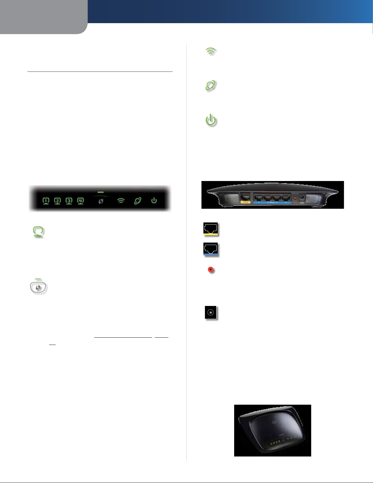
Front Panel
1, 2, 3, 4 (Green) These numbered LEDs,
corresponding with the numbered ports on the
Router’s back panel, serve two purposes. If the
LED is continuously lit, the Router is successfully
connected to a device through that port. A
flashing LED indicates network activity over
that port.
Wi-Fi Protected Setup Button If you have
client devices, such as wireless adapters, that
support Wi-Fi Protected Setup, then you can
use Wi-Fi Protected Setup to automatically
configure wireless security for your wireless
network(s).
Wireless (Green) The Wireless LED lights up
when the wireless feature is enabled. If the LED
is flashing, the Router is actively sending or
receiving data over the network.
Internet (Green) The Internet LED lights up
when there is a connection made through the
Internet port. A flashing LED indicates network
activity over the Internet port.
Power (Green) The Power LED lights up
and will stay on while the Router is powered
on. When the Router goes through its selfdiagnostic mode during every boot-up, this
LED will flash. When the diagnostic is complete,
the LED will be solidly lit.
Back Panel
Internet The Internet port is where you
connect your cable or DSL Internet connection.
1, 2, 3, 4 These Ethernet ports (1, 2, 3, 4) connect
the Router to PCs on your wired network and
other Ethernet network devices.
Reset There are two ways to reset the Router’s
factory defaults. Either press and hold the Reset
Button for approximately five seconds, or restore
the defaults from Administration > Factory
Defaults in the Router’s web-based utility.
Power The Power port is where you connect
the power adapter.
To use Wi-Fi Protected Setup, run the Setup
Wizard, or refer to Wi-Fi Protected Setup, page
10.
Wi-Fi Protected Setup LED (Green/
Amber) It lights up green when wireless
security is enabled. The LED flashes green for
two minutes during Wi-Fi Protected Setup.
The LED lights up amber if there is an error
during the Wi-Fi Protected Setup process. Make
sure the client device supports Wi-Fi Protected
Setup. Wait until the LED is off, and then try again.
The LED flashes amber when a Wi-Fi Protected
Setup session is active, and a second session
begins. The Router supports one session at a
time. Wait until the LED is off before starting the
next Wi-Fi Protected Setup session.
Wireless-G Broadband Router
Placement Options
There are two ways to physically install the Router. The
first way is to place the Router horizontally on a surface.
The second way is to mount the Router on a wall.
Horizontal Placement
The Router has four rubber feet on its bottom panel. Place
the Router on a level surface near an electrical outlet.
1
Page 6
Chapter 1
Product Overview
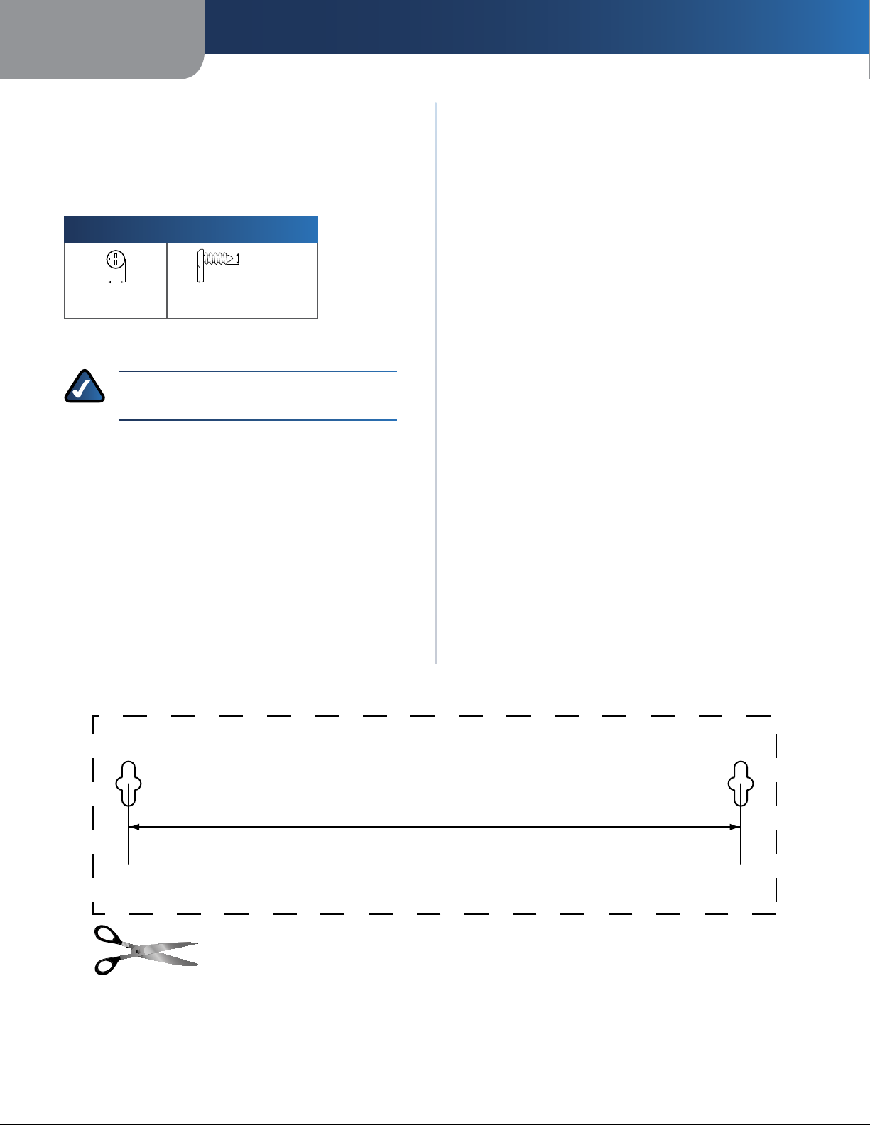
Wall-Mounting Placement
The Router has two wall-mount slots on its bottom
panel. The distance between the slots is 152 mm
(6 inches).
Two screws are needed to mount the Router.
Suggested Mounting Hardware
4-5 mm 1-1.5 mm
†Note: Mounting hardware illustrations are not
to scale.
NOTE: Linksys is not responsible for damages
incurred by insecure wall-mounting hardware.
2.5-3.0 mm
Follow these instructions:
1. Determine where you want to mount the Router. Make
sure that the wall you use is smooth, flat, dry, and
sturdy. Also make sure the location is within reach of
an electrical outlet.
2. Drill two holes into the wall. Make sure the holes are
152 mm (6 inches) apart.
3. Insert a screw into each hole and leave 3 mm
(0.12 inches) of its head exposed.
4. Position the Router so the wall-mount slots line up
with the two screws.
5. Place the wall-mount slots over the screws and slide
the Router down until the screws fit snugly into the
wall-mount slots.
Wireless-G Broadband Router
152 mm
Print this page at 100% size.
Cut along the dotted line, and place on the wall to drill precise spacing.
Wall Mounting Template
2
Page 7

Chapter 2
Wireless Security Checklist
Chapter 2: Wireless Security Checklist
Wireless networks are convenient and easy to install, so
homes with high-speed Internet access are adopting them
at a rapid pace. Because wireless networking operates by
sending information over radio waves, it can be more
vulnerable to intruders than a traditional wired network.
Like signals from your cellular or cordless phones, signals
from your wireless network can also be intercepted. Since
you cannot physically prevent someone from connecting
to your wireless network, you need to take some additional
steps to help keep your network secure.
1. Change the default wireless
network name or SSID
Wireless devices have a default wireless network name
or Service Set Identifier (SSID) set by the factory. This
is the name of your wireless network, and can be up
to 32 characters in length. Linksys wireless products
use linksys as the default wireless network name. You
should change the wireless network name to something
unique to distinguish your wireless network from other
wireless networks that may exist around you, but do not
use personal information (such as your Social Security
number) because this information may be available for
anyone to see when browsing for wireless networks.
4. Enable encryption
Encryption protects data transmitted over a wireless
network. Wi-Fi Protected Access (WPA/WPA2) and Wired
Equivalent Privacy (WEP) offer different levels of security
for wireless communication. Currently, devices that are
Wi-Fi certified are required to support WPA2, but are not
required to support WEP.
A network encrypted with WPA/WPA2 is more secure
than a network encrypted with WEP, because WPA/WPA2
uses dynamic key encryption. To protect the information
as it passes over the airwaves, you should enable the
highest level of encryption supported by your network
equipment.
WEP is an older encryption standard and may be the
only option available on some older devices that do not
support WPA.
General Network Security Guidelines
Wireless network security is useless if the underlying
network is not secure.
• Password protect all computers on the network and
individually password protect sensitive files.
• Change passwords on a regular basis.
• Install anti-virus software and personal firewall
software.
2. Change the default password
For wireless products such as access points and routers, you
will be asked for a password when you want to change their
settings. These devices have a default password set by the
factory. The Linksys default password is admin. Hackers
know these defaults and may try to use them to access
your wireless device and change your network settings.
To help thwart any unauthorized changes, customize the
device’s password so it will be hard to guess.
3. Enable MAC address filtering
Linksys routers give you the ability to enable Media Access
Control (MAC) address filtering. The MAC address is a
unique series of numbers and letters assigned to every
networking device. With MAC address filtering enabled,
wireless network access is provided solely for wireless
devices with specific MAC addresses. For example, you can
specify the MAC address of each computer in your home
so that only those computers can access your wireless
network.
• Disable file sharing (peer-to-peer). Some applications
may open file sharing without your consent and/or
knowledge.
Additional Security Tips
• Keep wireless routers, access points, or gateways away
from exterior walls and windows.
• Turn wireless routers, access points, or gateways
off when they are not being used (at night, during
vacations).
• Use strong passphrases that are at least eight characters
in length. Combine letters and numbers to avoid using
standard words that can be found in the dictionary.
WEB: For more information on wireless
security, visit www.linksys.com/security
Wireless-G Broadband Router
3
Page 8
Chapter 3
Advanced Configuration
Chapter 3: Advanced Configuration
After setting up the Router with the Setup Wizard (located
on the CD-ROM), the Router will be ready for use. If you’d
like to change its advanced settings, use the Router’s webbased utility. This chapter describes each web page of the
utility and each page’s key functions. You can access the
utility via a web browser on a computer connected to the
Router.
The web-based utility has these main tabs: Setup,
Wireless, Security, Access Restrictions, Applications &
Gaming, Administration, and Status. Additional tabs will
be available after you click one of the main tabs.
NOTE: When first installing the Router, you
should use the Setup Wizard on the Setup
CD-ROM. If you want to configure advanced
settings, use this chapter to learn about the
web-based utility.
How to Access the Web-Based Utility
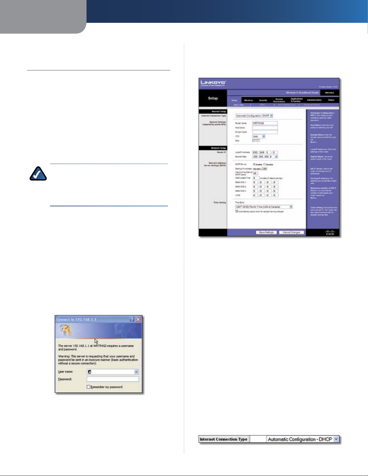
Setup > Basic Setup
The first screen that appears is the Basic Setup screen. This
allows you to change the Router’s general settings.
To access the web-based utility, launch the web browser on
your computer, and enter the Router’s default IP address,
192.168.1.1, in the Address field. Then, press Enter.
A password request screen will appear. (Non-Windows
XP users will see a similar screen.) Leave the User name
field blank. Then enter the password you set up during
the Setup Wizard. (If you did not run the Setup Wizard,
then use the default password, admin. You can set a new
password from the Administration tab’s Management
screen.) Click OK to continue.
Password Screen
Setup > Basic Setup
Internet Setup
The Internet Setup section configures the Router to your
Internet connection. Most of this information can be
obtained through your Internet Service Provider (ISP).
Internet Connection Type
Select the type of Internet connection your ISP provides
from the drop-down menu. The available types are:
• Automatic Configuration - DHCP
• Static IP
• PPPoE
• PPTP
• L2TP
• Telstra Cable
Automatic Configuration - DHCP
The default Internet Connection Type is Automatic
Configuration - DHCP. Keep the default only if your ISP
supports DHCP or if you connect using a dynamic IP address.
(This option usually applies to cable connections.)
Wireless-G Broadband Router
Internet Connection Type > Automatic Configuration - DHCP
4
Page 9
Chapter 3
Advanced Configuration
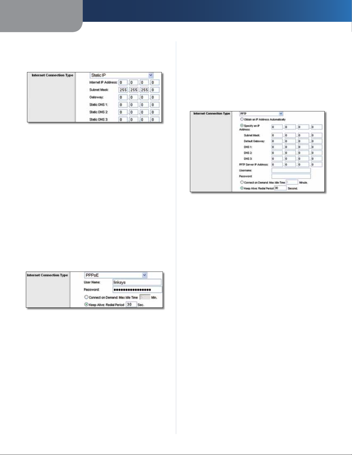
Static IP
If you are required to use a permanent IP address to
connect to the Internet, select Static IP.
Internet Connection Type > Static IP
Internet IP Address This is the Router’s IP address, when
seen from the Internet. Your ISP will provide you with the
IP Address you need to specify.
Subnet Mask This is the Router’s Subnet Mask, as seen
by users on the Internet (including your ISP). Your ISP will
provide you with the Subnet Mask.
Gateway Your ISP will provide you with the Gateway
address, which is the ISP server’s IP address.
Static DNS Your ISP will provide you with at least one
DNS (Domain Name System) server IP Address.
PPPoE
Some DSL-based ISPs use PPPoE (Point-to-Point Protocol
over Ethernet) to establish Internet connections. If you are
connected to the Internet through a DSL line, check with
your ISP to see if they use PPPoE. If they do, you will have
to enable PPPoE.
you are disconnected, then the Router will automatically
re-establish your connection. To use this option, select
Keep Alive. In the Redial Period field, specify how often
the Router should check the Internet connection. The
default is 30 seconds.
PPTP
Point-to-Point Tunneling Protocol (PPTP) is a service that
applies to connections in Europe only.
Internet Connection Type > PPTP
If your ISP supports DHCP or you are connecting through
a dynamic IP address, then select Obtain an IP Address
Automatically. If you are required to use a permanent IP
address to connect to the Internet, then select Specify an
IP Address. Then configure the following:
• Specify an IP Address This is the Router’s IP address,
as seen from the Internet. Your ISP will provide you
with the IP Address you need to specify.
• Subnet Mask This is the Router’s Subnet Mask, as
seen by users on the Internet (including your ISP). Your
ISP will provide you with the Subnet Mask.
Internet Connection Type > PPPoE
User Name and Password Enter the User Name and
Password provided by your ISP.
Connect on Demand: Max Idle Time You can configure
the Router to cut the Internet connection after it has been
inactive for a specified period of time (Max Idle Time). If
your Internet connection has been terminated due to
inactivity, Connect on Demand enables the Router to
automatically re-establish your connection as soon as you
attempt to access the Internet again. To use this option,
select Connect on Demand. In the Max Idle Time field,
enter the number of minutes you want to elapse before
your Internet connection terminates. The default is 5
minutes.
Keep Alive: Redial Period If you select this option, the
Router will periodically check your Internet connection. If
Wireless-G Broadband Router
• Default Gateway Your ISP will provide you with the
IP address of the ISP server.
• DNS 1-3 Your ISP will provide you with at least one
DNS (Domain Name System) server IP address.
PPTP Server IP Address Your ISP will provide you with
the IP address of the PPTP server.
Username and Password Enter the Username and
Password provided by your ISP.
Connect on Demand: Max Idle Time You can configure
the Router to cut the Internet connection after it has been
inactive for a specified period of time (Max Idle Time). If
your Internet connection has been terminated due to
inactivity, Connect on Demand enables the Router to
automatically re-establish your connection as soon as you
attempt to access the Internet again. To use this option,
select Connect on Demand. In the Max Idle Time field,
enter the number of minutes you want to elapse before
your Internet connection terminates. The default is 5
minutes.
5
Page 10
Chapter 3
Advanced Configuration
Keep Alive: Redial Period
Router will periodically check your Internet connection. If
you are disconnected, then the Router will automatically
re-establish your connection. To use this option, select
Keep Alive. In the Redial Period field, specify how often the
Router should check the Internet connection. The default is
30 seconds.
If you select this option, the
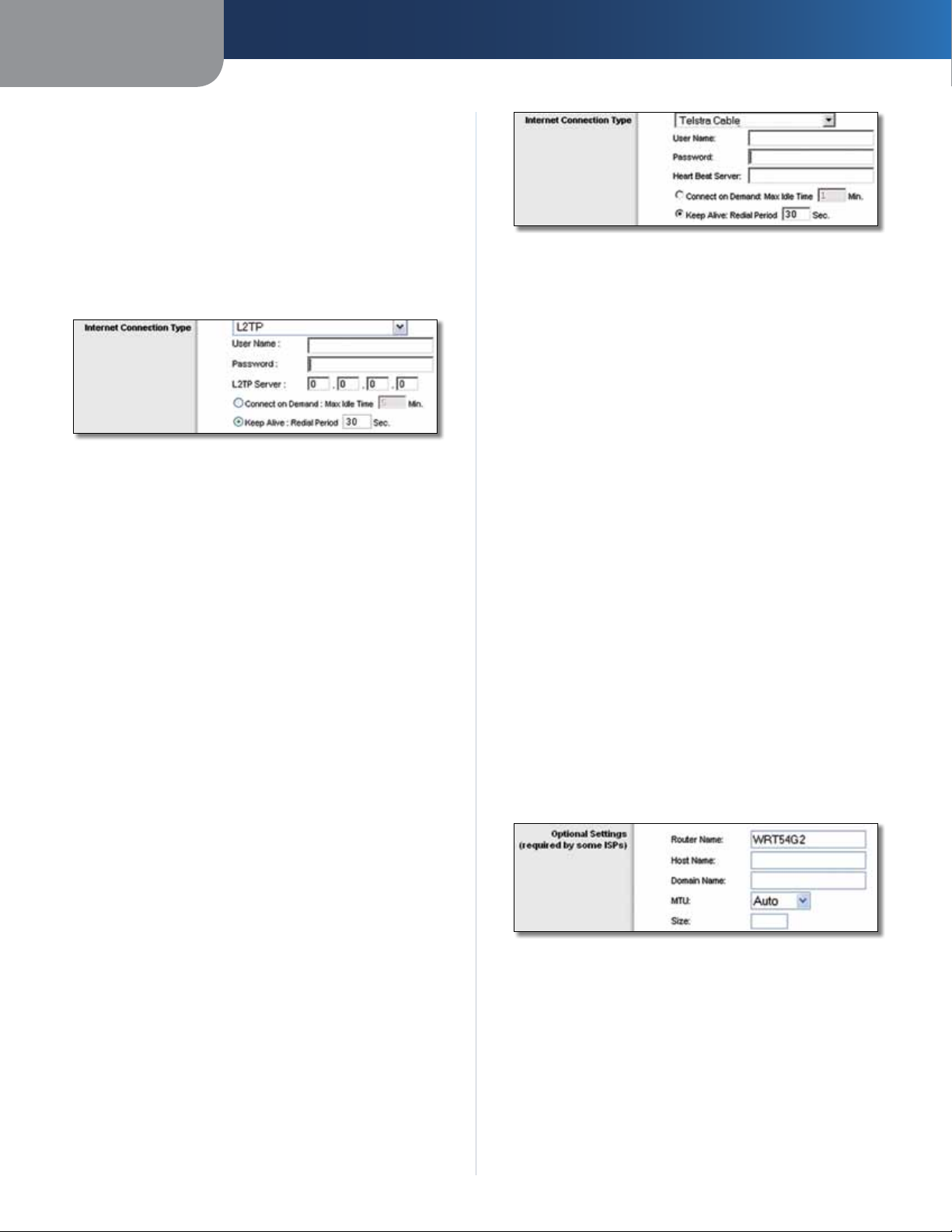
L2TP
L2TP is a service that applies to connections in Israel only.
Internet Connection Type > L2TP
User Name and Password Enter the User Name and
Password provided by your ISP.
L2TP Server This is the IP address of the L2TP Server.
Your ISP will provide you with the IP address you need to
specify.
Connect on Demand: Max Idle Time You can configure
the Router to cut the Internet connection after it has been
inactive for a specified period of time (Max Idle Time). If
your Internet connection has been terminated due to
inactivity, Connect on Demand enables the Router to
automatically re-establish your connection as soon as you
attempt to access the Internet again. To use this option,
select Connect on Demand. In the Max Idle Time field,
enter the number of minutes you want to elapse before
your Internet connection terminates. The default is 5
minutes.
Keep Alive: Redial Period If you select this option, the
Router will periodically check your Internet connection. If
you are disconnected, then the Router will automatically
re-establish your connection. To use this option, select
Keep Alive. In the Redial Period field, specify how often
the Router should check the Internet connection. The
default is 30 seconds.
Internet Connection Type > Telstra Cable
User Name and Password Enter the User Name and
Password provided by your ISP.
Heart Beat Server This is the IP address of the Heartbeat
Server. Your ISP will provide you with the IP Address you
need to specify.
Connect on Demand: Max Idle Time You can configure
the Router to cut the Internet connection after it has been
inactive for a specified period of time (Max Idle Time). If
your Internet connection has been terminated due to
inactivity, Connect on Demand enables the Router to
automatically re-establish your connection as soon as you
attempt to access the Internet again. To use this option,
select Connect on Demand. In the Max Idle Time field,
enter the number of minutes you want to have elapsed
before your Internet connection terminates. The default is
5 minutes.
Keep Alive: Redial Period If you select this option, the
Router will periodically check your Internet connection. If
you are disconnected, then the Router will automatically
re-establish your connection. To use this option, select
Keep Alive. In the Redial Period field, specify how often
the Router should check the Internet connection. The
default is 30 seconds.
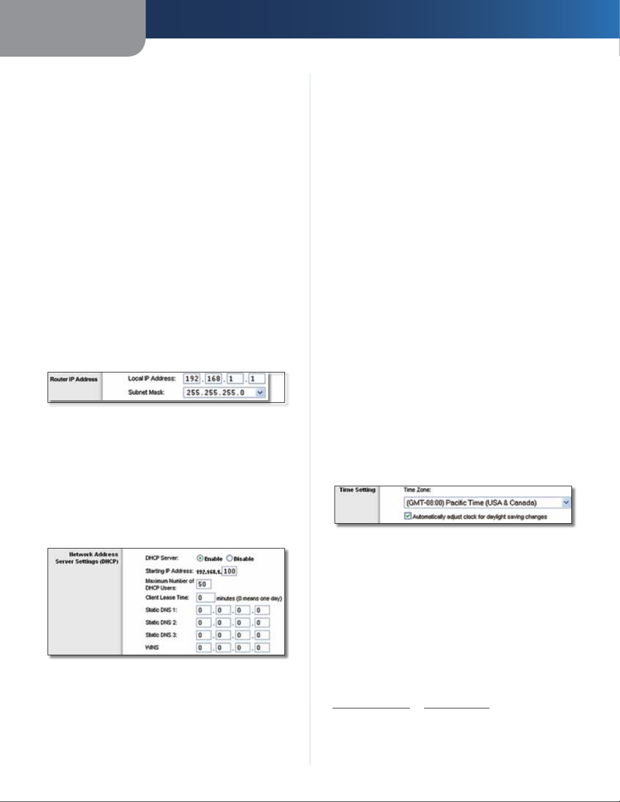
Optional Settings
Some of these settings may be required by your ISP. Verify
with your ISP before making any changes.
Telstra Cable
Telstra Cable is a service that applies to connections in
Australia only. If your ISP uses HeartBeat Signal (HBS), then
select Telstra Cable.
Wireless-G Broadband Router
Optional Settings
Router Name In this field, you can enter a name of up to
39 characters to represent the Router.
Host Name/Domain Name These fields allow you to
supply a host and domain name for the Router. Some ISPs,
usually cable ISPs, require these names as identification.
You may have to check with your ISP to see if your
broadband Internet service has been configured with a
host and domain name. In most cases, leaving these fields
blank will work.
6
Page 11
Chapter 3
Advanced Configuration
MTU MTU is the Maximum Transmission Unit. It specifies
the largest packet size permitted for Internet transmission.
Select Manual if you want to manually enter the largest
packet size that is transmitted. To have the Router select
the best MTU for your Internet connection, keep the
default, Auto.
Size When Manual is selected in the MTU field, this option
is enabled. Leave this value in the 1200 to 1500 range. The
default size depends on the Internet Connection Type:
• DHCP, Static IP, or Telstra: 1500
• PPPoE: 1492
• PPTP or L2TP: 1460
Network Setup
The Network Setup section changes the settings on the
network connected to the Router’s Ethernet ports. Wireless
Setup is performed through the Wireless tab.
Router IP
This presents both the Router’s IP Address and Subnet
Mask as seen by your network.
Router IP Address
Network Address Server Settings (DHCP)
The settings allow you to configure the Router’s Dynamic
Host Configuration Protocol (DHCP) server function. The
Router can be used as a DHCP server for your network. A
DHCP server automatically assigns an IP address to each
computer on your network. If you choose to enable the
Router’s DHCP server option, make sure there is no other
DHCP server on your network.
Router’s default IP address is 192.168.1.1, the Starting IP
Address must be 192.168.1.2 or greater, but smaller than
192.168.1.253. The default is 192.168.1.100
Maximum Number of DHCP Users Enter the maximum
number of PCs that you want the DHCP server to assign
IP addresses to. This number cannot be greater than 253.
The default is 50.
Client Lease Time The Client Lease Time is the amount
of time a network user will be allowed connection to the
Router with their current dynamic IP address. Enter the
amount of time, in minutes, that the user will be “leased”
this dynamic IP address. After the time is up, the user will
be automatically assigned a new dynamic IP address, or
the lease will be renewed. The default is 0 minutes, which
means one day.
Static DNS (1-3)
the Internet translates domain or website names into
Internet addresses or URLs. Your ISP will provide you with at
least one DNS Server IP Address. If you wish to use another,
enter that IP Address in one of these fields. You can enter up
to three DNS Server IP Addresses here. The Router will use
these for quicker access to functioning DNS servers
WINS The Windows Internet Naming Service (WINS)
manages each PC’s interaction with the Internet. If you
use a WINS server, enter that server’s IP Address here.
Otherwise, leave this blank.
The Domain Name System (DNS) is how
.
.
Time Setting
Select the time zone in which your network functions
from this drop-down menu. (You can even automatically
adjust for daylight saving time.)
Time Setting
Network Address Server Settings (DHCP)
DHCP Server DHCP is enabled by factory default. If you
already have a DHCP server on your network, or you do
not want a DHCP server, then select Disable (no other
DHCP features will be available).
Starting IP Address Enter a value for the DHCP server
to start with when is
Wireless-G Broadband Router
suing IP addresses. Because the
Click Save Settings to apply your changes, or click Cancel
Changes to clear your changes.
Setup > DDNS
The Router offers a Dynamic Domain Name System (DDNS)
feature. DDNS lets you assign a fixed host and domain
name to a dynamic Internet IP address. It is useful when
you are hosting your own website, FTP server, or other
server behind the Router.
Before you can use this feature, you need to sign
up for DDNS service with a DDNS service provider,
www.dyndns.org or www.TZO.com. If you do not want
to use this feature, keep the default setting, Disable.
7
Page 12
Chapter 3
Advanced Configuration
DDNS
The Router offers a Dynamic Domain Name System (DDNS)
feature. DDNS lets you assign a fixed host and domain
name to a dynamic Internet IP address. It is useful when
you are hosting your own website, FTP server, or other
server behind the Router.
Before you can use this feature, you need to sign up for
DDNS service at one of two DDNS service providers,
DynDNS.org or TZO.com. If you do not want to use this
feature, keep the default, Disable.
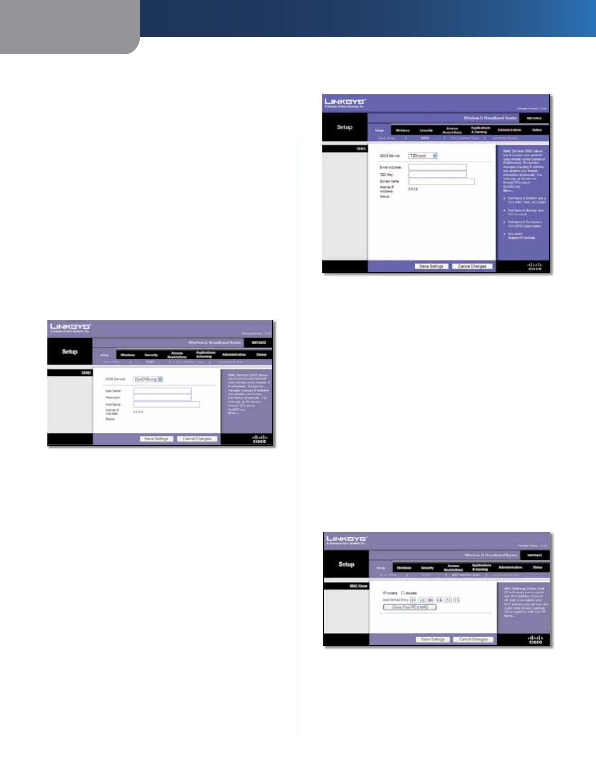
DDNS Service
If your DDNS service is provided by DynDNS.org, then
select DynDNS.org from the drop-down menu. If your
DDNS service is provided by TZO, then select TZO.com.
The features available on the DDNS screen will vary,
depending on which DDNS service provider you use.
DynDNS.org
TZO.com
Setup > DDNS > TZO
E-mail Address, TZO Key, and Domain Name Enter the
settings of the account you set up with TZO.
Internet IP Address The Router’s Internet IP address is
displayed. Because it is dynamic, it will change.
Setup > DDNS > DynDNS
User Name Enter the User Name for your DDNS account.
Password Enter the Password for your DDNS account.
Host Name The is the DDNS URL assigned by the DDNS
service.
Internet IP Address The Router’s Internet IP address is
displayed. Because it is dynamic, it will change.
Status The status of the DDNS service connection is
displayed.
Click Save Settings to apply your changes, or click Cancel
Changes to clear your changes.
Status The status of the DDNS service connection is
displayed.
Click Save Settings to apply your changes, or click Cancel
Changes to clear your changes.
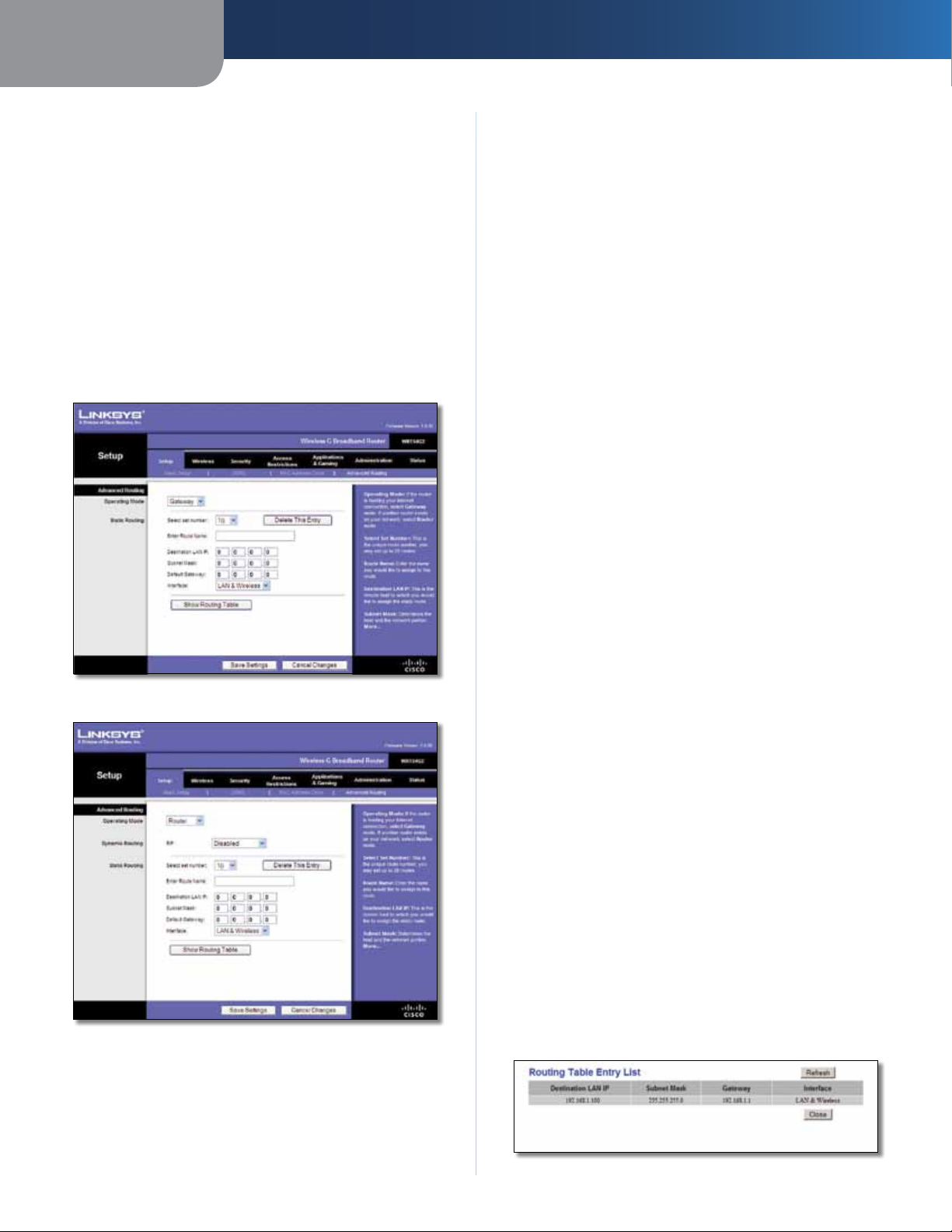
Setup > MAC Address Clone
Some ISPs will require you to register a MAC address
in order to access the Internet. A MAC address is a
12-digit code assigned to a unique piece of hardware for
identification. If you do not wish to re-register the MAC
address with your ISP, you can use the MAC Address Clone
feature to assign the currently registered MAC address to
the Router.
Wireless-G Broadband Router
Setup > MAC Address Clone
MAC Address Clone
Enable/Disable To have the MAC Address cloned, select
Enable.
8
Page 13
Chapter 3
Advanced Configuration
User Defined Entry Enter the MAC Address registered
with your ISP here.
Clone Your PC’s MAC Clicking this button will clone the
MAC address of the computer you are using.
Click Save Settings to apply your changes, or click Cancel
Changes to clear your changes.
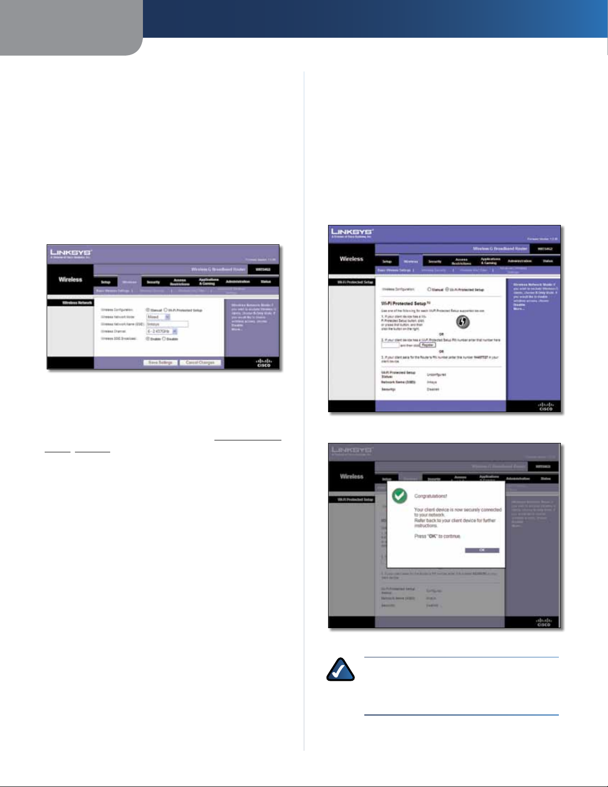
Setup > Advanced Routing
This screen is used to set up the Router’s advanced routing
functions. NAT routes the host Router ‘s network connection
to the Internet. Dynamic Routing automatically adjusts
how packets travel on your network. Static Routing sets
up a fixed route to another network destination.
Router is chosen, Dynamic Routing will be available as
an option.
Dynamic Routing
RIP This feature enables the Router to automatically
adjust to physical changes in the network’s layout and
exchange routing tables with the other router(s). The
Router determines the network packets’ route based on
the fewest number of hops between the source and the
destination. This feature is Disabled by default. From the
drop-down menu, you can also select LAN & Wireless,
which performs dynamic routing over your Ethernet and
wireless networks. You can also select WAN (Internet),
which performs dynamic routing with data coming from
the Internet. Finally, selecting Both enables dynamic
routing for both networks, as well as data from the
Internet.
Select set number To set up a static route between the
Router and another network, select a number from the
Static Routing drop-down list. (A static route is a predetermined pathway that network information must travel
to reach a specific host or network.) Enter the information
described below to set up a new static route. (Click the
Delete This Entry button to delete a static route.)
Setup > Advanced Routing (Gateway)
Setup > Advanced Routing (Router )
Enter Route Name Enter a name for the Route here,
using a maximum of 25 alphanumeric characters.
Destination LAN IP The Destination LAN IP is the address
of the remote network or host to which you want to assign
a static route.
Subnet Mask The Subnet Mask determines which
portion of a Destination LAN IP address is the network
portion, and which portion is the host portion.
Default Gateway This is the IP address of the gateway
device that allows for contact between the Router and the
remote network or host.
Interface This interface tells you whether the Destination
IP Address is on the LAN & Wireless (Ethernet and wireless
networks) or the WAN (Internet).
Delete This Entry To delete a route, select its number
from the drop-down menu, and click this button.
Show Routing Table Click Show Routing Table to open
a screen displaying how data is routed through your local
network. For each route, the Destination LAN IP address,
Subnet Mask, Gateway, and Interface are displayed. Click
Refresh to update the information. Click Close to exit this
screen.
Advanced Routing
Operating Mode Select the mode in which this Router
will function. If this Router is hosting your network’s
connection to the Internet, select Gateway. If another
Router exists on your network, select Router. When
Wireless-G Broadband Router
Routing Table
9
Page 14
Chapter 3
Advanced Configuration
Click Save Settings to apply your changes, or click Cancel
Changes to clear your changes.
Wireless > Basic Wireless Settings
The basic settings for wireless networking are set on this
screen.
There are two ways to configure the Router’s wireless
network(s), manual and Wi-Fi Protected Setup.
Wi-Fi Protected Setup is a feature that makes it easy to set
up your wireless network. If you have client devices, such
as wireless adapters, that support Wi-Fi Protected Setup,
then you can use Wi-Fi Protected Setup.
Wireless SSID Broadcast When wireless clients survey
the local area for wireless networks to associate with, they
will detect the SSID broadcast by the Router. To broadcast
the Router’s SSID, keep the default, Enabled. If you do not
want to broadcast the Router’s SSID, then select Disabled.
Click Save Settings to apply your changes, or click Cancel
Changes to clear your changes.
Wi-Fi Protected Setup
There are three methods available. Use the method that
applies to the client device you are configuring.
Wireless > Basic Wireless Settings (Manual Setup)
Wireless Configuration To manually configure your
wireless network, select Manual. Proceed to the “Wireless
Network (Manual)” section. To use Wi-Fi Protected Setup,
select Wi-Fi Protected Setup. Proceed to Wi-Fi Protected
Setup, page 10.
Wireless Network (Manual)
Wireless Network Mode From this drop-down menu,
you can select the wireless standards running on your
network. If you have Wireless-N, Wireless-G, and Wireless-B
devices in your network, keep the default setting, Mixed.
If you have only Wireless-G and Wireless-B devices in your
network, select BG-Mixed. If you have only Wireless-N
devices, select Wireless-N Only. If you have only
Wireless-G devices, select Wireless-G Only. If you have
only Wireless-B devices, select Wireless-B Only. If your
network has no wireless devices, or if you want to disable
wireless networking, select Disabled.
Wireless Network Name (SSID) The SSID is the network
name shared among all points in a wireless network.
The SSID must be identical for all devices in the wireless
network. It is case-sensitive and must not exceed
32 keyboard characters. For added security, you should
change the default SSID (linksys) to a unique name.
Wireless Channel Select the channel from the list
provided to correspond with your network settings. All
devices in your wireless network must be broadcast on
the same channel in order to function correctly.
Wireless > Basic Wireless Settings (Wi-Fi Protected Setup)
Wi-Fi Protected Setup > Congratulations
NOTE: Wi-Fi Protected Setup configures one
client device at a time. Repeat the instructions
for each client device that supports Wi-Fi
Protected Setup.
Wireless-G Broadband Router
10
Page 15
Chapter 3
Advanced Configuration
Method #1
Use this method if your client device has a Wi-Fi Protected
Setup button.
1. Click or press the Wi-Fi Protected Setup button on
the client device.
2. Click the Wi-Fi Protected Setup button on this
screen.
3. After the client device has been configured, click
OK. Then refer back to your client device or its
documentation for further instructions.
Method #2
Use this method if your client device has a Wi-Fi Protected
Setup PIN number.
1. Enter the PIN number in the field on this screen.
2. Click Register.
3. After the client device has been configured, click
OK. Then refer back to your client device or its
documentation for further instructions.
Method #3
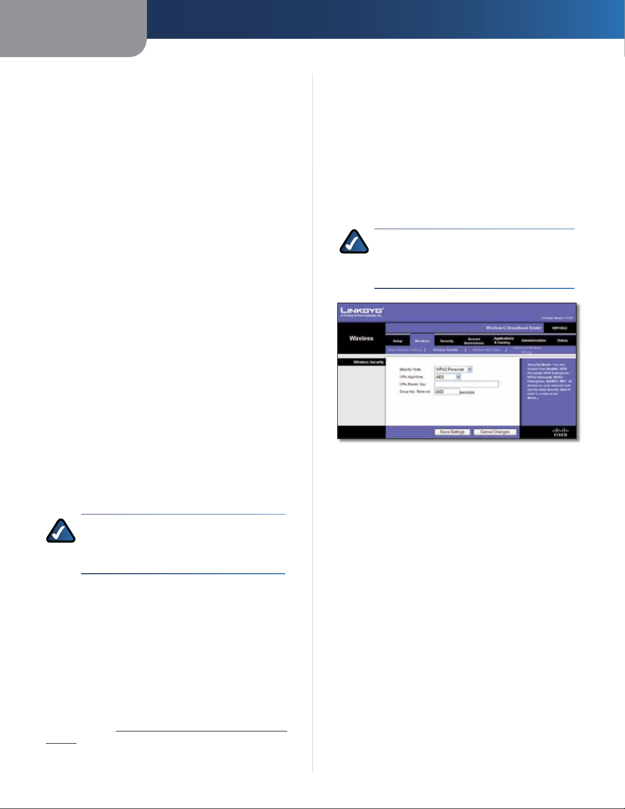
Wireless Security
Wireless security is strongly recommended, and WPA2 is
the strongest method available. Use WPA2 if it is supported
by all of your wireless devices.
Security Mode
Select the security method for your wireless network. If
you do not want to use wireless security, keep the default,
Disabled.
WPA2 Personal
NOTE: If you are using WPA2 or WPA, each
device in your wireless network MUST use the
same WPA method and shared key, or else the
network will not function properly.
Use this method if your client device asks for the Router’s
PIN number.
1. Enter the PIN number listed on this screen. (It is also
listed on the label on the bottom of the Router.)
2. After the client device has been configured, click
OK. Then refer back to your client device or its
documentation for further instructions.
The Wi-Fi Protected Setup Status, Network Name (SSID),
Security, Encryption, and Passphrase are displayed at the
bottom of the screen.
NOTE: If you have client devices that do not
support Wi-Fi Protected Setup, note the wireless
settings, and then manually configure those
client devices.
Wireless > Wireless Security
The Wireless Security settings configure the security of
your wireless network. There are six wireless security mode
options supported by the Router: WPA2 Personal, WPA
Personal, WPA2 Enterprise, WPA Enterprise, RADIUS, and
WEP. WPA (Wi-Fi Protected Access) is a stronger security
standard than WEP (Wireless Equivalent Privacy), and
WPA2 is even more secure than WPA. RADIUS is Remote
Authentication Dial-In User Service. These six are briefly
discussed here. For more information about wireless
security, refer to Chapter 2: Wireless Security Checklist,
page 3.
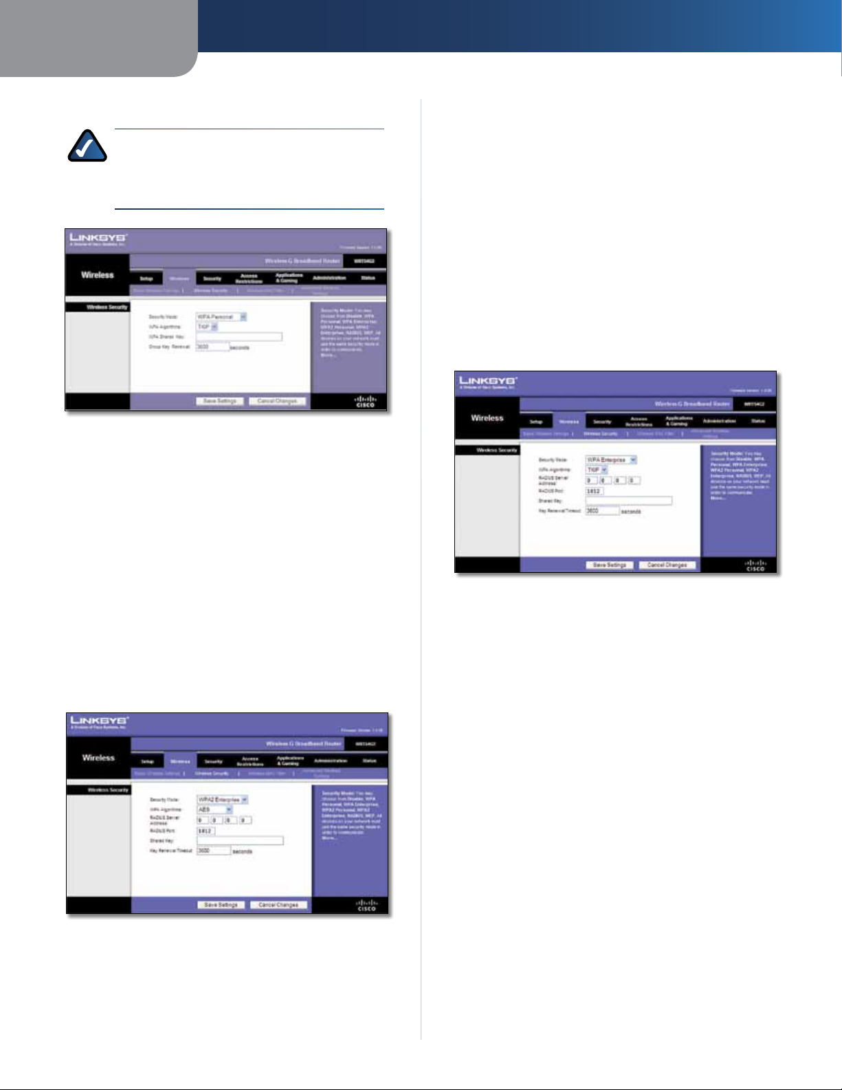
Security Mode > WPA2 Personal
WPA Algorithm WPA2 supports two encryption methods,
TKIP and AES, with dynamic encryption keys. Select the
type of algorithm, AES, or TKIP + AES. The default is AES.
WPA Shared Key Enter a WPA Shared Key of 8-63
characters.
Group Key Renewal Enter a Group Key Renewal period,
which instructs the Router how often it should change the
encryption keys. The default is 3600 seconds.
Wireless-G Broadband Router
11
Page 16
Chapter 3
Advanced Configuration
WPA Personal
NOTE: If you are using WPA2 or WPA, each
device in your wireless network MUST use the
same WPA method and shared key, or else the
network will not function properly.
Security Mode > WPA Personal
WPA Algorithm WPA supports two encryption methods,
TKIP and AES, with dynamic encryption keys. Select
the type of algorithm, TKIP or AES. (AES is a stronger
encryption method than TKIP.)
RADIUS Server Address Enter the IP Address of the
RADIUS server.
RADIUS Port Enter the port number of the RADIUS
server. The default is 1812.
Shared Key Enter the key shared between the Router
and the server.
Key Renewal Timeout Enter a Key Renewal Timeout
period, which instructs the Router how often it should
change the encryption keys. The default is 3600 seconds.
WPA Enterprise
This option features WPA used in coordination with a
RADIUS server. (This should only be used when a RADIUS
server is connected to the Router.)
WPA Shared Key Enter the key shared by the Router and
your other network devices. It must have 8-63 characters.
Group Key Renewal Enter a Key Renewal period, which
tells the Router how often it should change the encryption
keys. The default is 3600 seconds.
WPA2 Enterprise
This option features WPA2 used in coordination with a
RADIUS server. (This should only be used when a RADIUS
server is connected to the Router.
Security Mode > WPA2 Enterprise
Security Mode > WPA Enterprise
WPA Algorithm WPA supports two encryption methods,
TKIP and AES, with dynamic encryption keys. Select
the type of algorithm, TKIP or AES. (AES is a stronger
encryption method than TKIP.)
RADIUS Server Address Enter the IP Address of the
RADIUS server.
RADIUS Port Enter the port number of the RADIUS
server. The default is 1812.
Shared Key Enter the key shared between the Router
and the server.
Key Renewal Timeout Enter a Key Renewal Timeout
period, which instructs the Router how often it should
change the encryption keys. The default is 3600 seconds.
WPA Algorithm WPA2 supports two encryption
methods, TKIP and AES, with dynamic encryption keys.
Select the type of algorithm, AES, or TKIP + AES. The
default is AES
Wireless-G Broadband Router
12
Page 17
Chapter 3
Advanced Configuration
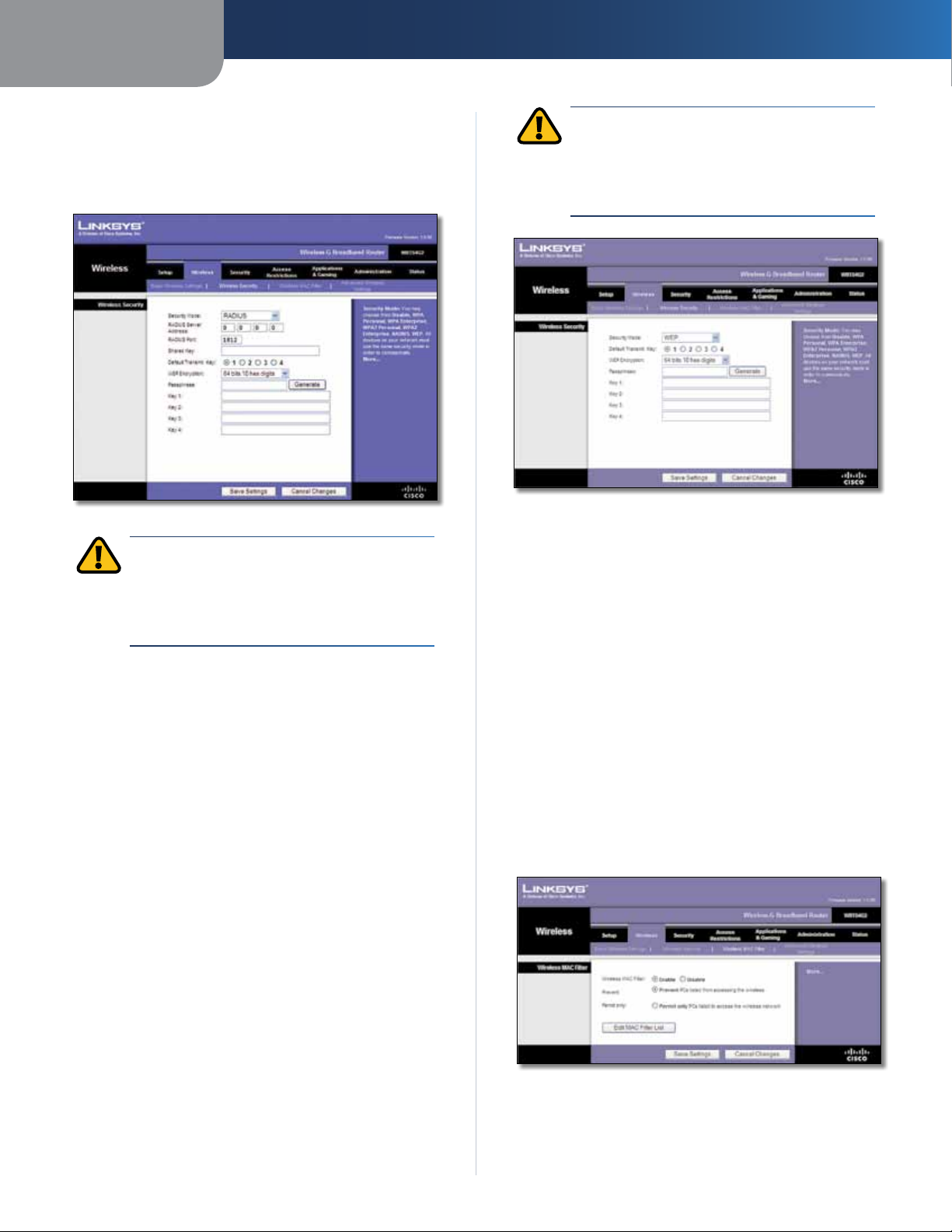
RADIUS
This option features WEP used in coordination with a
RADIUS server. (This should only be used when a RADIUS
server is connected to the Router.)
Security Mode > RADIUS
IMPORTANT: If you are using WEP encryption,
each device in your wireless network MUST
use the same WEP encryption method and
encryption key, or else your wireless network will
not function properly.
RADIUS Server Address Enter the IP Address of the
RADIUS server.
RADIUS Port Enter the port number of the RADIUS
server. The default is 1812.
Shared Key Enter the key shared between the Router
and the server.
Default Transmit Key Select a Default Transmit Key
(choose which Key to use). The default is 1.
WEP Encryption Select a level of WEP encryption,
64 bits 10 hex digits or 128 bits 26 hex digits. The
default is 64 bits 10 hex digits.
IMPORTANT: If you are using WEP encryption,
each device in your wireless network MUST
use the same WEP encryption method and
encryption key, or else your wireless network will
not function properly.
Security Mode > WEP
Default Transmit Key Select a Default Transmit Key
(choose which Key to use). The default is 1.
WEP Encryption Select a level of WEP encryption, 64 bits
10 hex digits or 128 bits 26 hex digits. The default is
64 bits 10 hex digits.
Passphrase Enter a Passphrase to automatically generate
WEP keys. Then click Generate.
Key 1-4 If you did not enter a Passphrase, enter the WEP
key(s) manually.
Click Save Settings to apply your changes, or click Cancel
Changes to clear your changes.
Wireless > Wireless MAC Filter
Wireless access can be filtered (restricted) by specifying the
MAC addresses of the devices in your wireless network.
Passphrase Enter a Passphrase to automatically generate
WEP keys. Then click Generate.
Key 1-4 If you did not enter a Passphrase, enter the WEP
key(s) manually.
WEP
WEP is a basic encryption method, which is not as secure
as WPA.
Wireless-G Broadband Router
Wireless > Wireless MAC Filter
13
Page 18
Chapter 3
Wireless MAC Filter
Advanced Configuration
Wireless MAC Filter
either permitting or blocking access, click Enable. If you do
not wish to filter users by MAC Address, keep the default,
Disable
Prevent Select this to block wireless access by MAC
Address. This button is selected by default.
Permit Only Select this to allow wireless access by MAC
Address. This button is not selected by default.
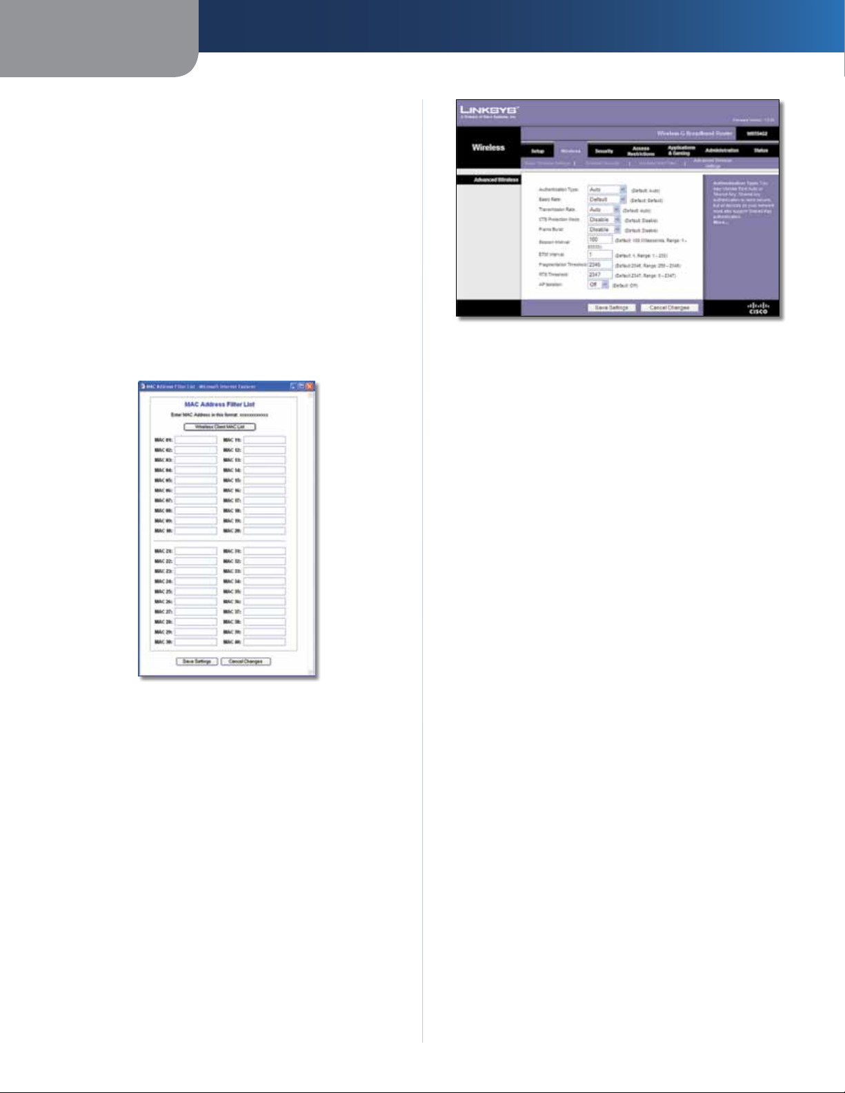
Edit MAC Filter List
Filter List screen. On this screen, you can list users, by MAC
Address, to whom you wish to provide or block access. For
easy reference, click Wireless Client MAC List to display a list
of network users by MAC Address
Click Save Settings to apply your changes, or click Cancel
Changes to clear your changes.
.
To filter wireless users by MAC Address,
Click this to open the MAC Address
.
MAC Address Filter List
Wireless > Advanced Wireless Settings
This Wireless > Advanced Wireless Settings screen is used
to set up the Router’s advanced wireless functions.
These settings should only be adjusted by an expert
administrator because incorrect settings can reduce
wireless performance.
Wireless > Advanced Wireless Settings
Advanced Wireless
Authentication Type The default is set to Auto, which
allows either Open System or Shared Key authentication
to be used. With Open System authentication, the sender
and the recipient do NOT use a WEP key for authentication.
With Shared Key authentication, the sender and recipient
use a WEP key for authentication.
Basic Rate The Basic Rate setting is not actually one rate
of transmission but a series of rates at which the Router
can transmit. The Router will advertise its Basic Rate to
the other wireless devices in your network, so they know
which rates will be used. The Router will also advertise that
it will automatically select the best rate for transmission.
The default setting is Default, for transmission at all
standard wireless rates (1-2 Mbps, 5.5 Mbps, 11 Mbps, 18
Mbps, and 24 Mbps). Other options are 1-2Mbps, for use
with older wireless technology, and All, for transmission
at all wireless rates. The Basic Rate is not the actual rate
of data transmission. If you want to specify the Router’s
rate of data transmission, configure the Transmission Rate
setting.
Transmission Rate The rate of data transmission should
be set depending on the speed of your wireless network.
You can select from a range of transmission speeds, or you
can select Auto to have the Router automatically use the
fastest possible data rate and enable the Auto-Fallback
feature. Auto-Fallback will negotiate the best possible
connection speed between the Router and a wireless
client. The default is Auto.
CTS Protection Mode CTS (Clear-To-Send) Protection
Mode should remain disabled unless you are having severe
problems with your Wireless-G products not being able
to transmit to the Router in an environment with heavy
802.11b traffic. This function boosts the Router’s ability
to catch all Wireless-G transmissions but will severely
decrease performance.
Wireless-G Broadband Router
Frame Burst Enabling this option should provide your
network with greater performance, depending on the
14
Page 19

Chapter 3
manufacturer of your wireless products. To turn on the
Frame Burst option, select Enable. The default is Disable.
Beacon Interval A beacon is a packet broadcast by the
Router to synchronize the wireless network. The default
is 100. Enter a value between 1 and 65,535 milliseconds.
The Beacon Interval value indicates the frequency interval
of the beacon.
DTIM Interval This value, between 1 and 255, indicates
the interval of the Delivery Traffic Indication Message
(DTIM). A DTIM field is a countdown field informing
clients of the next window for listening to broadcast
and multicast messages. When the Router has buffered
broadcast or multicast messages for associated clients, it
sends the next DTIM with a DTIM Interval value. Its clients
hear the beacons and awaken to receive the broadcast
and multicast messages. The default is 1.
Fragmentation Threshold This value specifies the
maximum size for a packet before data is fragmented
into multiple packets. If you experience a high packet
error rate, you may slightly increase the Fragmentation
Threshold. Setting the Fragmentation Threshold too low
may result in poor network performance. Only minor
reduction of the default value is recommended. In most
cases, it should remain at its default value of 2346.
RTS Threshold Should you encounter inconsistent data
flow, only minor reduction of the default value, 2347, is
recommended. If a network packet is smaller than the
preset RTS threshold size, the RTS/CTS mechanism will
not be enabled. The Router sends Request to Send (RTS)
frames to a particular receiving station and negotiates
the sending of a data frame. After receiving an RTS, the
wireless station responds with a Clear to Send (CTS) frame
to acknowledge the right to begin transmission. The RTS
Threshold value should remain at its default value of
2347.
AP Isolation This isolates all wireless clients and wireless
devices on your network from each other. Wireless devices
will be able to communicate with the Router but not with
each other. To use this function, select On. AP Isolation is
turned Off by default.
Click Save Settings to apply your changes, or click Cancel
Changes to clear your changes.
Advanced Configuration
Security > Firewall
Firewall
Firewall Protection To use firewall protection, keep the
default selection, Enable. To turn off firewall protection,
select Disable.
Block WAN Requests
Block Anonymous Internet Requests This feature
makes it more difficult for outside users to work their
way into your network. This feature is selected by default.
Deselect the feature to allow anonymous Internet
requests
Filter Multicast Multicasting allows for multiple
transmissions to specific recipients at the same time. If
multicasting is permitted, then the Router will allow IP
multicast packets to be forwarded to the appropriate
computers. This feature is selected by default. Deselect
this feature to disable it.
Filter Internet NAT Redirection This feature uses
port forwarding to block access to local servers from
local networked computers. Select Filter Internet NAT
Redirection to filter Internet NAT redirection. This feature
is not selected by default.
Filter IDENT (Port 113) This feature keeps port 113 from
being scanned by devices outside of your local network.
This feature is selected by default. Deselect this feature to
disable it.
Click Save Settings to apply your changes, or click Cancel
Changes to clear your changes.
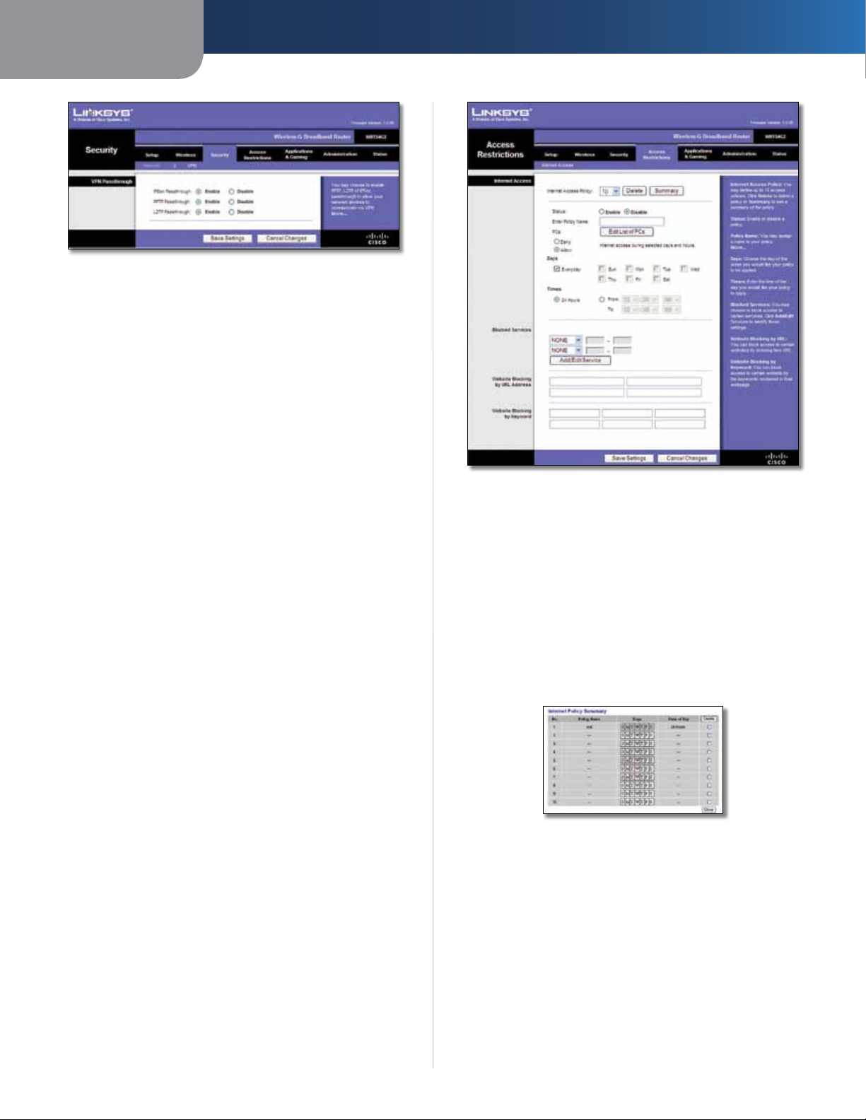
Security > VPN Passthrough
.
Security > Firewall
The Security > Firewall screen is used to configure a firewall
that can filter out various types of unwanted traffic on the
Router’s local network.
Wireless-G Broadband Router
The Security > VPN Passthrough screen allows you to enable
VPN tunnels using IPSec, PPTP, or L2TP protocols to pass
through the Router’s firewall.
15
Page 20
Chapter 3
Security > VPN Passthrough
VPN Passthrough
IPSec Passthrough Internet Protocol Security (IPSec) is
a suite of protocols used to implement secure exchange
of packets at the IP layer. To allow IPSec tunnels to pass
through the Router, keep the default, Enable.
PPTP Passthrough Point-to-Point Tunneling Protocol
(PPTP) allows the Point-to-Point Protocol (PPP) to be
tunneled through an IP network. To allow PPTP tunnels to
pass through the Router, keep the default, Enable.
L2TP Passthrough Layer 2 Tunneling Protocol is the
method used to enable Point-to-Point sessions via the
Internet on the Layer 2 level. To allow L2TP tunnels to pass
through the Router, keep the default, Enable.
Click Save Settings to apply your changes, or click Cancel
Changes to clear your changes.
Access Restrictions > Internet Access
The Access Restrictions > Internet Access screen allows you
to block or allow specific kinds of Internet usage and
traffic, such as Internet access, designated services, and
websites during specific days and times.
Advanced Configuration
Access Restrictions > Internet Access
Internet Access
Internet Access Policy Access can be managed by a
policy. Use the settings on this screen to establish an
access policy (after Save Settings is clicked). Selecting a
policy from the drop-down menu will display that policy’s
settings. To delete a policy, select that policy’s number
and click Delete. To view all the policies, click Summary.
(To delete policies from the Summary screen, select the
policy or policies, and click Delete. To return to the Internet
Access screen, click Close.)
Wireless-G Broadband Router
Internet Policy Summary
Status Policies are disabled by default. To enable a policy,
select the policy number from the drop-down menu, and
select Enable.
To create an Internet Access policy:
1. Select a number from the Internet Access Policy dropdown menu.
2. To enable this policy, select Enable.
3. Enter a Policy Name in the field provided.
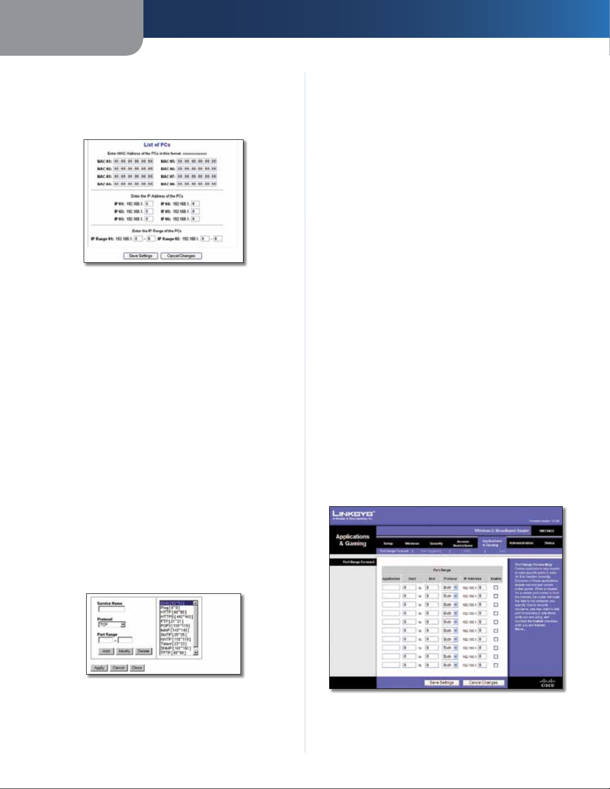
4. Click Edit List of PCs to select which PCs will be affected
by the policy. The List of PCs screen appears. You can
16
Page 21
Chapter 3
Advanced Configuration
select a PC by MAC Address or IP Address. You can also
enter a range of IP Addresses if you want this policy
to affect a group of PCs. After making your changes,
click Save Settings to apply your changes or Cancel
Changes to clear your changes. Then click Close.
List of PCs
5. Select the appropriate option, Deny or Allow,
depending on whether you want to block or allow
Internet access for the PCs you listed on the List of PCs
screen.
6. Decide which days and what times you want this policy
to be enforced. Select the individual days during which
the policy will be in effect, or select Everyday. Then
enter a range of hours and minutes during which the
policy will be in effect, or select 24 Hours.
7. Select any Blocked Services or Website Blocking you
wish to use.
8. Click Save Settings to save the policy’s settings, or
click Cancel Changes to cancel the policy’s settings.
Blocked Services
You can filter access to various services accessed over the
Internet, such as FTP or telnet, by selecting services from
the drop-down menus next to Blocked Services. (You can
block up to 20 services.) Then enter the range of ports you
want to filter.
To modify a service, select it from the list on the right.
Change its name, protocol setting, or port range. Then
click Modify.
To delete a service, select it from the list on the right. Then
click Delete.
When you are finished making changes on the Port
Services screen, click Apply to save the changes. If you
want to clear your changes, click Cancel. To close the Port
Services screen and return to the Access Restrictions screen,
click Close.
Website Blocking by URL Address
If you want to block websites with specific URL addresses,
enter each URL in a separate field next to Website Blocking
by URL Address.
Website Blocking by Keyword
If you want to block websites using specific keywords,
enter each keyword in a separate field next to Website
Blocking by Keyword.
Click Save Settings to apply your changes, or click Cancel
Changes to clear your changes.
Applications and Gaming > Port Range Forward
The Applications & Gaming > Port Range Forward screen
allows you to set up public services on your network, such as
web servers, ftp servers, e-mail servers, or other specialized
Internet applications. (Specialized Internet applications are
any applications that use Internet access to perform functions
such as videoconferencing or online gaming. Some Internet
applications may not require any forwarding.)
If the service you want to block is not listed or you want to
edit a service’s settings, then click Add/Edit Service. The
Port Services screen appears.
Port Services
To add a service, enter the service’s name in the Service
Name field. Select its protocol from the Protocol dropdown menu, and enter its range in the Port Range fields.
Then click Add.
Wireless-G Broadband Router
Applications and Gaming > Port Range Forward
17
Page 22
Chapter 3
Advanced Configuration
Port Range Forward
To forward a port, enter the information on each line for
the criteria required.
Application In this field, enter the name you wish to give
the application. Each name can be up to 12 characters.
Start/End This is the port range. Enter the number that
starts the port range in the Start column and the number
that ends the range in the End column.
Protocol Select the protocol used for this application,
either TCP or UDP, or Both.
IP Address For each application, enter the IP Address of
the PC running the specific application.
Enable Select Enable to enable port forwarding for the
relevant application.
Click Save Settings to apply your changes, or click Cancel
Changes to clear your changes.
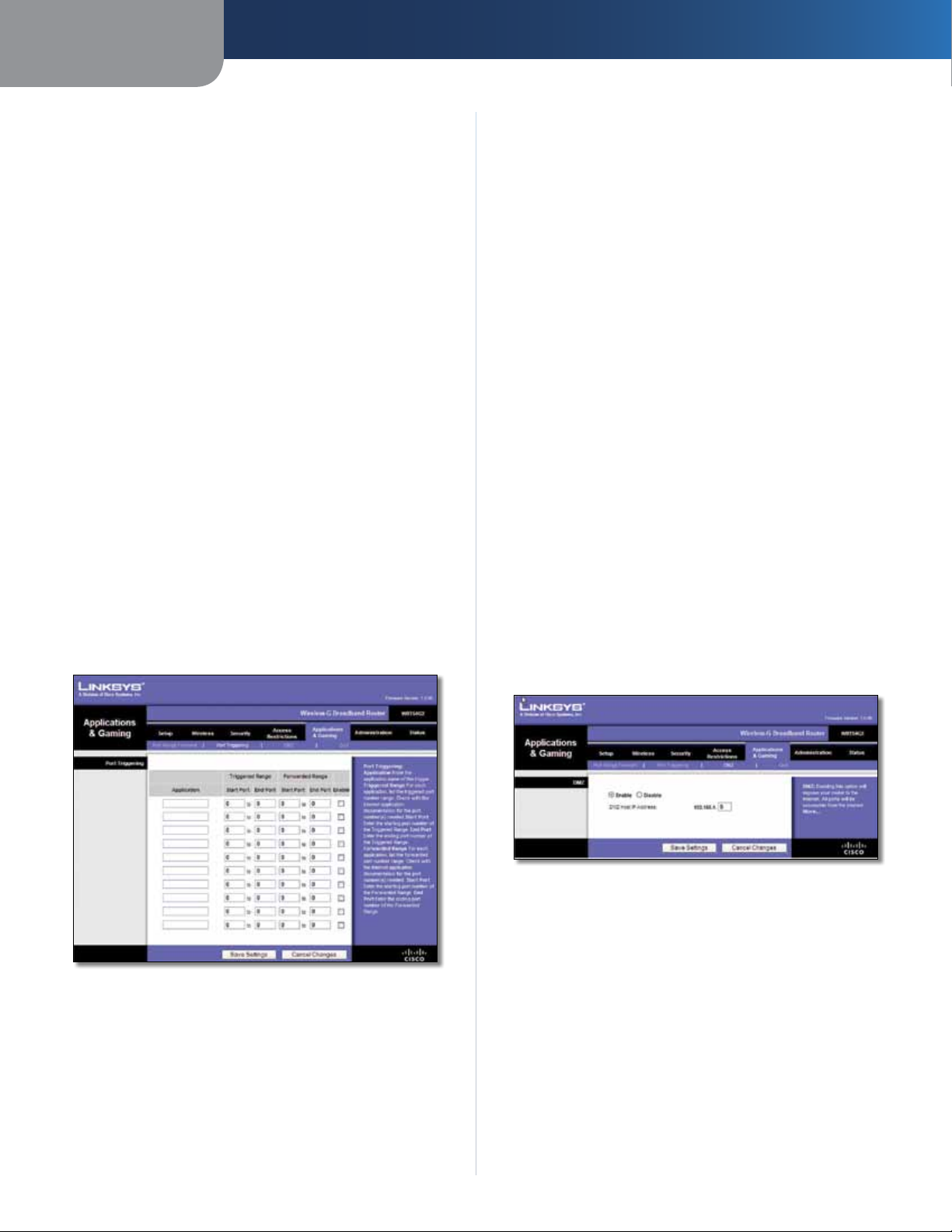
Applications & Gaming > Port Triggering
The Applications & Gaming > Port Triggering screen allows
the Router to watch outgoing data for specific port
numbers. The IP address of the computer that sends the
matching data is remembered by the Router, so that when
the requested data returns through the Router, the data is
pulled back to the proper computer by way of IP address
and port mapping rules.
Start Port Enter the starting port number of the Triggered
Range.
End Port Enter the ending port number of the Triggered
Range.
Forwarded Range
For each application, list the forwarded port number
range. Check with the Internet application documentation
for the port number(s) needed.
Start Port Enter the starting port number of the
Forwarded Range.
End Port Enter the ending port number of the Forwarded
Range.
Enable Select Enable to enable port triggering for the
applicable application.
Click Save Settings to apply your changes, or click Cancel
Changes to clear your changes.
Applications and Gaming > DMZ
The DMZ feature allows one network computer to be
exposed to the Internet for use of a special-purpose
service such as Internet gaming or videoconferencing.
DMZ hosting forwards all the ports at the same time to
one PC. The Port Range Forward feature is more secure
because it only opens the ports you want to have opened,
while DMZ hosting opens all the ports of one computer,
exposing the computer to the Internet.
Applications and Gaming > Port Triggering
Port Triggering
Application Enter the application name of the trigger.
Triggered Range
For each application, list the triggered port number range.
Check with the Internet application documentation for
the port number(s) needed.
Wireless-G Broadband Router
Applications and Gaming > DMZ
DMZ
Any PC whose port is being forwarded must have its DHCP
client function disabled and should have a new static IP
address assigned to it because its IP address may change
when using the DHCP function.
To expose one PC, select Enable. Then, enter the
computer’s IP address in the DMZ Host IP Address field. This
feature is disabled by default.
Click Save Settings to apply your changes, or click Cancel
Changes to clear your changes.
18
Page 23
Chapter 3
Advanced Configuration
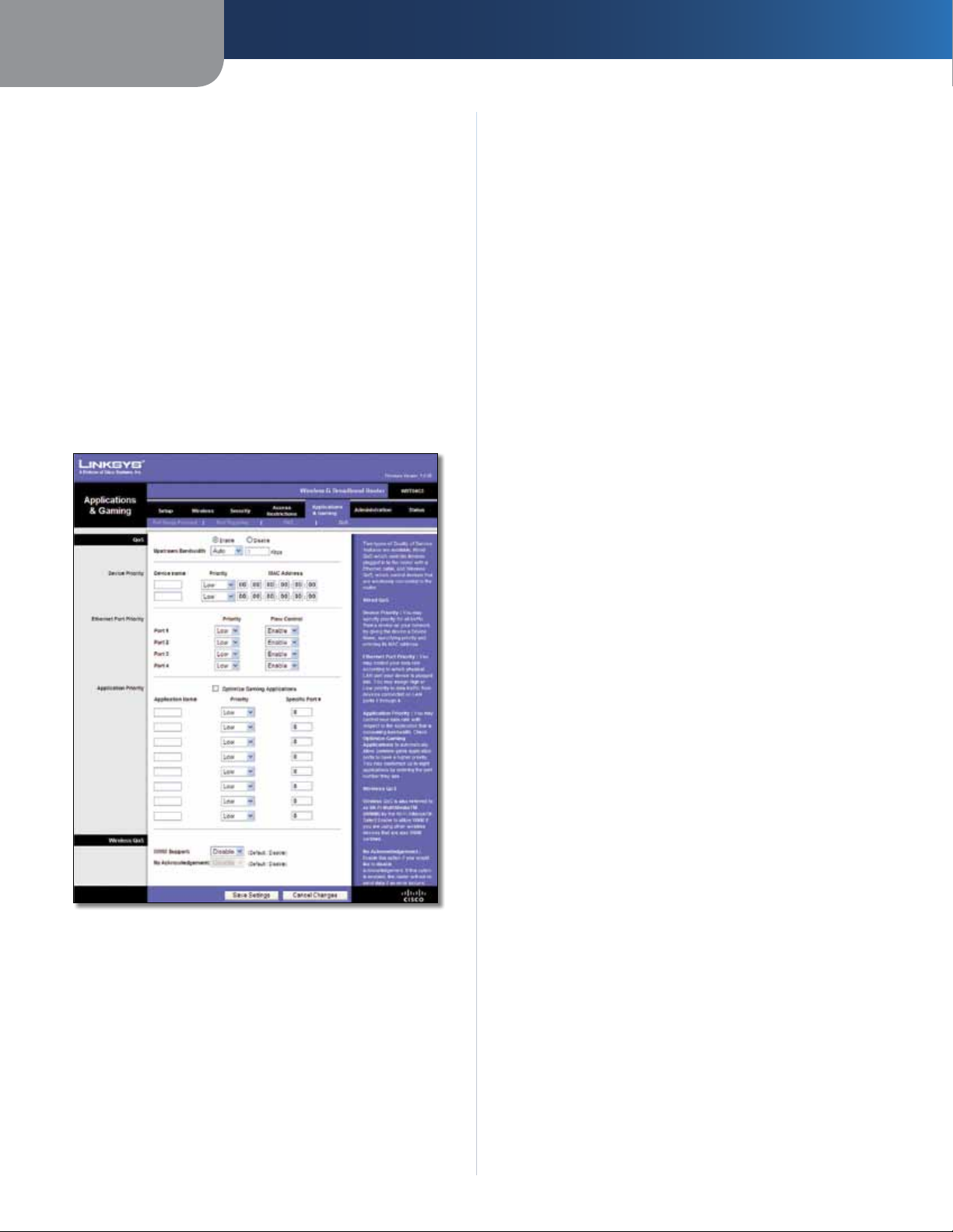
Applications and Gaming > QoS
Quality of Service (QoS) ensures better service to
high-priority types of network traffic, which may
involve demanding, real-time applications, such as
videoconferencing.
There are three types of QoS available: Device Priority,
Ethernet Port Priority, and Application Priority.
QoS
Enable/Disable To enable QoS, select Enable. Otherwise,
select Disable. QoS is disabled by default.
Upstream Bandwidth Select Auto or Manual from
the drop-down menu. Manual allows you to specify the
maximum outgoing bandwidth that applications can
utilize.
Priority Select High or Low in the Priority column. The
Router’s four ports have been assigned low priority by
default.
Flow Control If you want the Router to control the
transmission of data between network devices, select
Enabled. To disable this feature, select Disabled. Ethernet
Port Priority QoS does not require support from your ISP
because the prioritized ports (LAN ports 1-4) are in your
network. This feature is enabled by default.
Application Priority
Application Priority QoS manages information as it is
transmitted and received. Depending on the settings of
the QoS screen, this feature will assign information a high
or low priority for the applications that you specify.
Optimize Gaming Applications Select this to
automatically allow common game application ports
to have a higher priority. These games include, but are
not limited to: Counter-Strike, Half-Life, Age of Empires,
EverQuest, Quake2/Quake3, and Diablo II. The default
setting is unselected.
Application Name Enter the name you wish to give the
application in the Application Name field.
Applications and Gaming > QoS
Device Priority
Enter the name of your network device in the Device name
field, enter its MAC Address, and then select its priority
from the drop-down menu.
Ethernet Port Priority
Ethernet Port Priority QoS allows you to prioritize
performance for the Router’s four ports, LAN Ports 1-4. For
each port, select the priority and flow control setting.
Priority Select High or Low to assign priority to the
application. The default selection is Low.
Specific Port # Enter the port number for the
application.
Wireless QoS
WMM Support Wi-Fi Multimedia (WMM), formerly
known as Wireless Multimedia Extensions (WME), is
a Wi-Fi Alliance certified feature, based on the IEEE
802.11e standard. This feature provides QoS to wireless
networks. It is especially suitable for voice, music and
video applications; for example, Voice over IP (VoIP), video
streaming, and interactive gaming. If you have other
devices on your wireless network that support WMM,
select Enabled. Otherwise, keep the default, Disabled.
No Acknowledgement This feature prevents the Router
from re-sending data if an error occurs. To use this feature,
select Enabled. Otherwise, keep the default, Disabled.
Click Save Settings to apply your changes, or click Cancel
Changes to clear your changes.
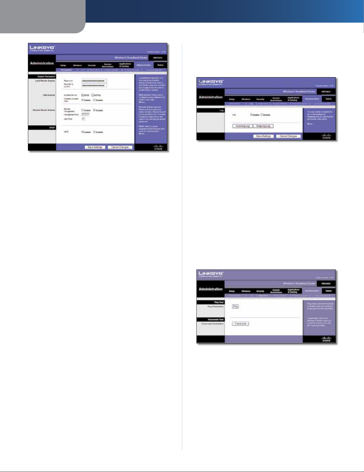
Administration > Management
The Administration > Management screen allows the
network’s administrator to manage specific Router
functions for access and security.
Wireless-G Broadband Router
19
Page 24
Chapter 3
Administration > Management
Router Password
Local Router Access
Router Password Enter a new Password for the Router.
Re-enter to confirm Enter the Password again to confirm.
Web Access
Access Server HTTP (HyperText Transport Protocol) is
the communications protocol used to connect to servers
on the World Wide Web. HTTPS uses SSL (Secured Socket
Layer) to encrypt data transmitted for higher security.
Select HTTP or HTTPS. The default is HTTP.
Advanced Configuration
Administration > Log
The Router can keep logs of all traffic for your Internet
connection.
Administration > Log
Log
Log To disable the Log function, keep the default setting,
Disable. To monitor traffic between the network and the
Internet, select Enable.
When you wish to view the logs, click Incoming Log or
Outgoing Log, depending on which you wish to view.
Click Save Settings to apply your changes, or click Cancel
Changes to clear your changes.
Administration > Diagnostics
The diagnostic tests (Ping and Traceroute) allow you to
check the connections of your network components.
Wireless Access Web If you are using the Router in
a public domain where you are giving wireless access
to your guests, you can disable wireless access to the
Router’s web-based utility. You will only be able to access
the web-based utility via a wired connection if you disable
the setting. Keep the default, Enable, to enable wireless
access to the Router’s web-based utility, or select Disable
to disable wireless access to the utility.
Remote Router Access
Remote Management To access the Router remotely,
from outside the network, select Enable.
Management Port Enter the port number that will be
open to outside access. You will need to enter the Router’s
password when accessing the Router this way, as usual.
Use https To require the use of HTTPS for remote access,
select this feature.
UPnP
UPnP Keep the default, Enable to enable the UPnP
feature; otherwise, select Disable.
Click Save Settings to apply your changes, or click Cancel
Changes to clear your changes.
Administration > Diagnostics
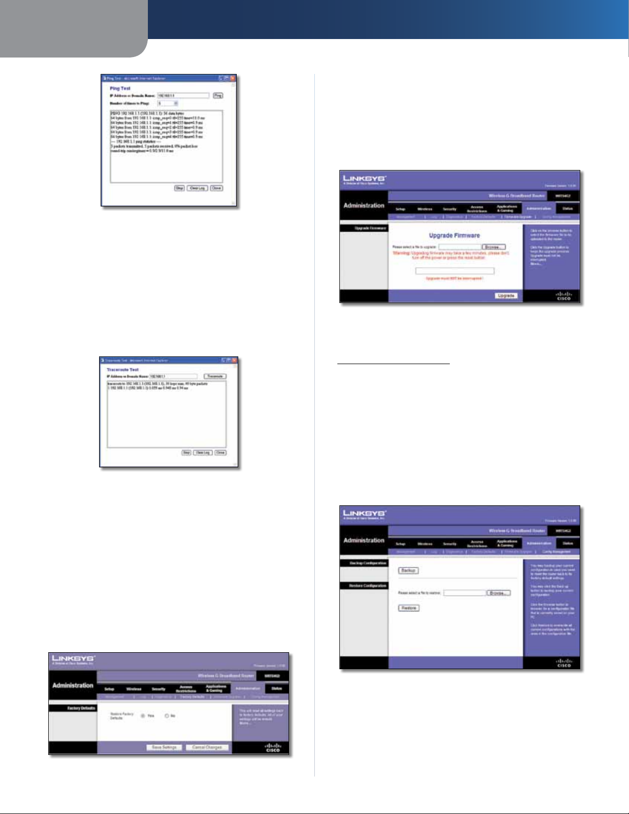
Ping Test
Ping The Ping test checks the status of a connection.
Click Ping to open the Ping Test screen. Enter the address
of the PC whose connection you wish to test and how
many times you wish to test it. Then, click Ping. The Ping
Test screen will show if the test was successful. To stop the
test, click Stop. Click Clear Log to clear the screen. Click
Close to return to the Diagnostics screen.
Wireless-G Broadband Router
20
Page 25
Chapter 3
Ping Test
Traceroute Test
Traceroute To test the performance of a connection,
click Traceroute to open the Traceroute Test screen. Enter
the address of the PC whose connection you wish to test
and click Traceroute. The Traceroute Test screen will show
if the test was successful. To stop the test, click Stop. Click
Clear Log to clear the screen. Click Close to return to the
Diagnostics screen.
Advanced Configuration
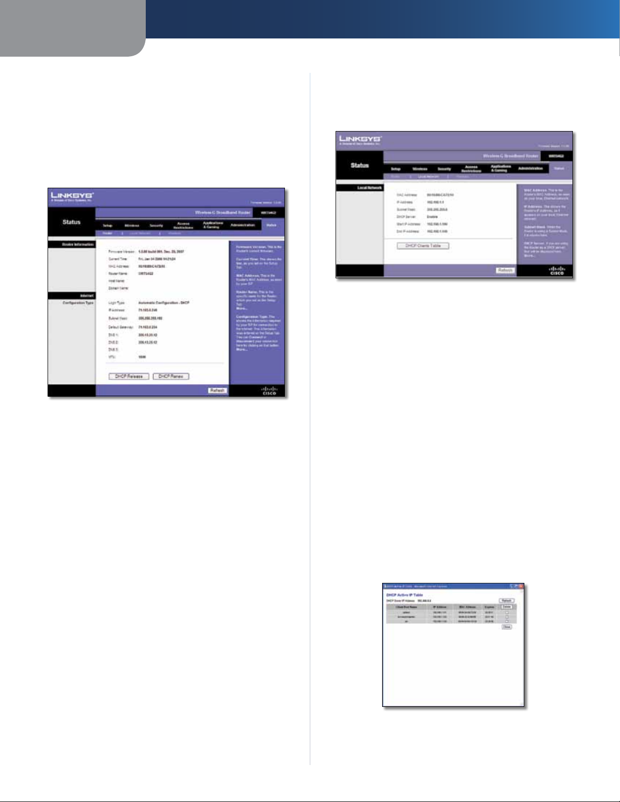
Administration > Upgrade Firmware
The Administration > Upgrade Firmware screen allows
you to upgrade the Router’s firmware. Do not upgrade
the firmware unless you are experiencing problems with
the Router or the new firmware has a feature you want
to use.
Administration > Upgrade Firmware
Before upgrading the firmware, download the Router’s
firmware upgrade file from the Linksys website,
www.linksysbycisco.com.
Traceroute Test
Administration > Factory Defaults
The Administration > Factory Defaults screen allows you
to restore the Router’s configuration to its factory default
settings.
Factory Defaults
Restore Factory Defaults To reset the Router’s settings
to the default values, select Yes, and then click Save
Settings. Any settings you have saved will be lost when
the default settings are restored.
Upgrade Firmware
Please select a file to upgrade Click Browse and select
the firmware upgrade file. Then c
the on-screen instructions.
lick Upgrade and follow
Administration > Config Management
This screen is used to back up or restore the Router’s
configuration file.
Administration > Config Management
Administration > Factory Defaults
Wireless-G Broadband Router
Backup Configuration
To back up the Router’s configuration file, click Backup.
Then follow the on-screen instructions.
21
Page 26
Chapter 3
Advanced Configuration
Restore Configuration
Please select a file to restore Click Browse and select
the configuration file. Then click Restore.
Status > Router
The Status > Router screen displays the Router’s current
status.
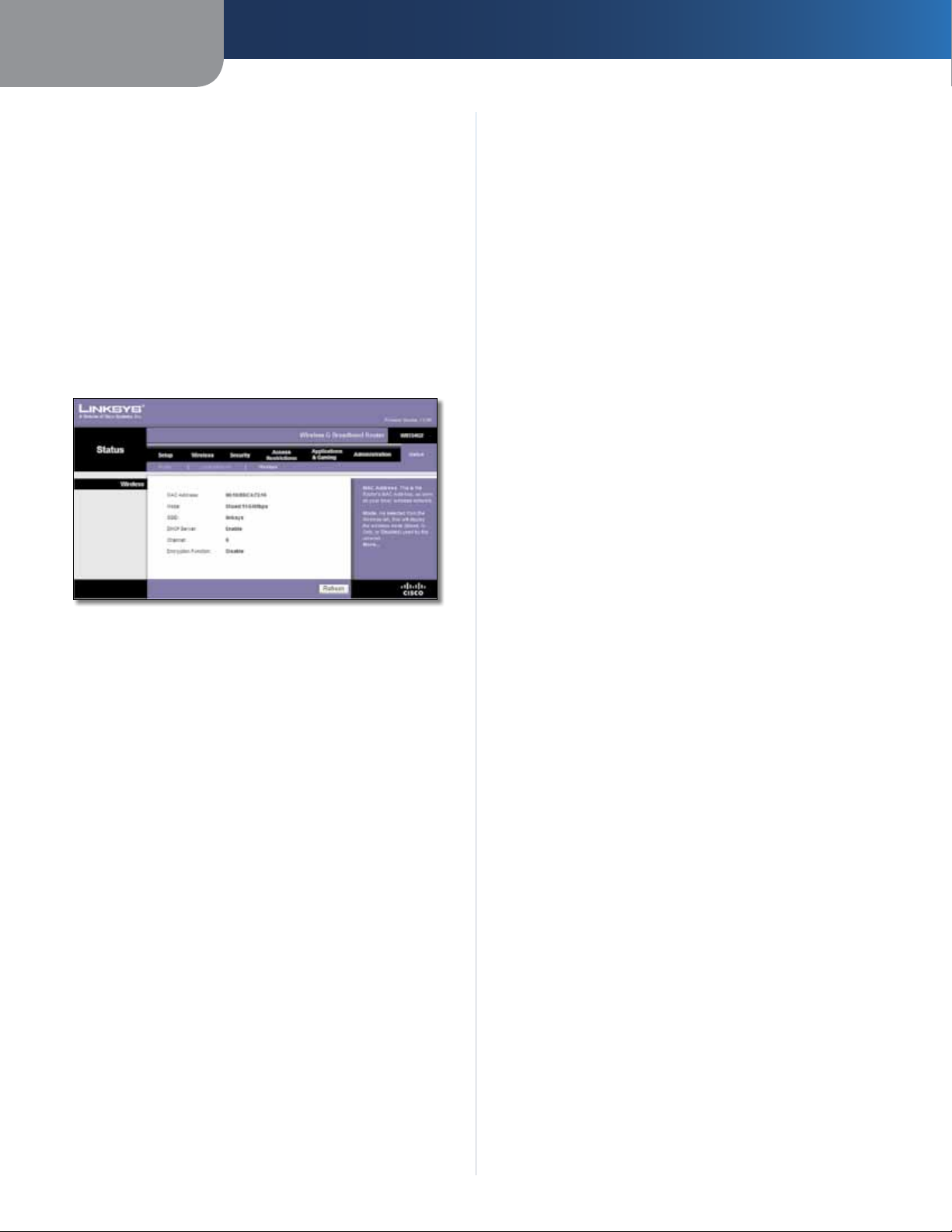
Status > Local Network
The Status > Local Network screen displays the status of
your network.
Status > Local Network
Local Network
MAC Address The MAC address of the Router’s local,
wired interface is displayed.
IP Address The Router’s IP address, as it appears on your
local network, is displayed.
Status > Router
Router Information
Firmware Version The version number of the Router’s
current firmware is displayed.
Current Time The time set on the Router’s clock is
displayed.
MAC Address The Router’s MAC Address, as seen by your
ISP, is displayed.
Router Name The Router Name of the Router is displayed
(if it was entered on the Setup > Basic Setup screen).
Host Name The Host Name of the Router is displayed (if it
was entered on the Setup > Basic Setup screen).
Domain Name The Domain Name of the Router is
displayed (if it was entered on the Setup > Basic Setup
screen).
Internet
Configuration Type
Subnet Mask The Subnet Mask of the Router is
displayed.
DHCP Server The status of the Router’s DHCP server
function is displayed.
Start IP Address For the range of IP addresses that can
be used by devices on your local network, the starting IP
address is displayed.
End IP Address For the range of IP addresses that can
be used by devices on your local network, the ending IP
address is displayed.
DHCP Clients Table Click this button to view a list of
computers or other devices that are using the Router as
a DHCP server.
This section shows the current network information
stored in the Router. The information varies depending on
the Internet connection type selected on the Setup > Basic
Setup screen.
Click Refresh to update the on-screen information.
Wireless-G Broadband Router
DHCP Clients Table
22
Page 27
Chapter 3
DHCP Client Table
The DHCP Client Table lists computers and other
devices that have been assigned IP addresses by the
Router. The list can be sorted by IP Address, MAC
Address, Interface, and Client Name. To remove a
DHCP client, select the Delete check box, and then
click Delete. To update the on-screen information,
click Refresh. To exit this screen and return to the Local
Network screen, click Close.
Status > Wireless
The Status > Wireless screen displays the status of your
wireless network.
Advanced Configuration
Status > Wireless
Wireless
MAC Address The MAC address of the Router’s local,
wireless interface is displayed.
Mode The wireless mode used by the network is
displayed.
SSID The name of the wireless network, which is also
called the SSID, is displayed.
DHCP Server The status of the DHCP server function is
displayed.
Channel The channel on which your wireless network is
broadcasting is displayed.
Encryption Function The status of the Router’s wireless
security feature is displayed.
Click Refresh to update the on-screen information.
Wireless-G Broadband Router
23
Page 28

Appendix A
Troubleshooting
Appendix A: Troubleshooting
Your computer cannot connect to the Internet.
Follow these instructions until your computer can connect
to the Internet:
• Make sure that the Router is powered on. The Power
LED should be lit and not flashing.
• If the Power LED is flashing, then power off all of
your network devices, including the modem, Router,
and computers. Then power on each device in the
following order:
1. Cable or DSL modem
2. Router
3. Computer
• Check the cable connections. The computer should
be connected to one of the ports numbered 1-4 on
the Router, and the modem must be connected to the
Internet port on the Router.
The modem does not have an Ethernet port.
The modem is a dial-up modem for traditional dial-up
service. To use the Router, you need a cable/DSL modem
and high-speed Internet connection.
When you double-click the web browser, you are
prompted for a username and password. If you want to
get rid of the prompt, follow these instructions.
Launch the web browser and perform the following steps
(these steps are specific to Internet Explorer but are similar
for other browsers):
1. Select Tools > Internet Options.
2. Click the Connections tab.
3. Select Never dial a connection.
4. Click OK.
The Router does not have a coaxial port for the cable
connection.
The Router does not replace your modem. You still need
your cable modem in order to use the Router. Connect your
cable connection to the cable modem, insert the setup
CD into your computer, and then follow the on-screen
instructions.
The computer cannot connect wirelessly to the network.
Make sure the wireless network name or SSID is the same
on both the computer and the Router. If you have enabled
wireless security, then make sure the same security
method and key are used by both the computer and the
Router.
You need to modify the settings on the Router.
You cannot use the DSL service to connect manually to
the Internet.
After you have installed the Router, it will automatically
connect to your Internet Service Provider (ISP), so you no
longer need to connect manually.
The DSL telephone line does not t into the Router’s
Internet port.
The Router does not replace your modem. You still need
your DSL modem in order to use the Router. Connect
the telephone line to the DSL modem, insert the setup
CD into your computer, and then follow the on-screen
instructions.
Open the web browser (for example, Internet Explorer or
Firefox), and enter the Router’s IP address in the address
field (the default IP address is 192.168.1.1). When
prompted, leave the User name field blank and enter the
password to the Router (the default is admin). Click the
appropriate tab to change the settings.
WEB: If your questions are not addressed
here, refer to the Linksys website,
www.linksysbycisco.com
Wireless-G Broadband Router
24
Page 29

Appendix B
Appendix B: Specifications
Model WRT54G2
Standards IEEE 802.3, IEEE 802.3u,
IEEE 802.11g, IEEE 802.11b
Ports Internet, Ethernet (1-4), Power
Button Reset, Wi-Fi Protected Setup™
LEDs Power, Internet, Ethernet (1-4),
Wireless, Wi-Fi Protected Setup™
Cabling Type CAT5
Number of Antennas 1 Internal Antenna
Detachable No
RF Power Output 18 dBm
UPnP able/cert Able
Security Features Stateful Packet Inspection (SPI)
Firewall, Internet Policy
Wireless Security Wi-Fi Protected Access™2 (WPA2),
WEP, Wireless MAC Filtering
Specifications
Environmental
Dimensions 7.99" x 1.38" x 6.30"
(203 x 35 x 160 mm)
Weight 9.88 oz (280 g)
Power External, 12V DC, 0.5A
Certications FCC, UL, ICES-003, RSS210, CE,
Wi-Fi CERTIFIED™ (802.11b,
802.11g), WPA2™, WMM®,
Wi-Fi Protected Setup™
Operating Temp. 32 to 104ºF (0 to 40ºC)
Storage Temp. -4 to 140ºF (-20 to 60ºC)
Operating Humidity 10 to 85%, Noncondensing
Storage Humidity 5 to 90%, Noncondensing
Wireless-G Broadband Router
25
Page 30

Appendix C
Warranty Information
Appendix C: Warranty Information
Limited Warranty
Linksys warrants that this Linksys hardware product will be
substantially free of defects in materials and workmanship
arising under normal use during the Warranty Period,
which begins on the date of purchase by the original enduser purchaser and lasts for the period specified below:
• Two (2) years for new product
• Ninety (90) days for refurbished product
This limited warranty is non-transferable and extends only
to the original end-user purchaser. Your exclusive remedy
and Linksys' entire liability under this limited warranty will
be for Linksys, at its option, to (a) repair the product with
new or refurbished parts, (b) replace the product with a
reasonably available equivalent new or refurbished Linksys
product or (c) refund the purchase price of the product less
any rebates. Any repaired or replacement products will
be warranted for the remainder of the original Warranty
Period or thirty (30) days, whichever is longer. All products
and/or parts that are replaced become the property of
Linksys.
This limited warranty shall apply in addition to any
statutory or other rights which you may have under a
contract of sale.
Exclusions and Limitations
This limited warranty does not apply if: (a) the product
assembly seal has been removed or damaged, (b) the
product has been altered or modified, except by Linksys, (c)
the product damage was caused by use with non-Linksys
products, (d) the product has not been installed, operated,
repaired or maintained in accordance with instructions
supplied by Linksys, (e) the product has been subjected to
abnormal physical or electrical stress, misuse, negligence
or accident, (f) the serial number on the Product has been
altered, defaced or removed or (g) the product is supplied
or licensed for beta, evaluation, testing or demonstration
purposes for which Linksys does not charge a purchase
price or licence fee.
ALL SOFTWARE PROVIDED BY LINKSYS WITH THE PRODUCT,
WHETHER FACTORY LOADED ON THE PRODUCT OR
CONTAINED ON MEDIA ACCOMPANYING THE PRODUCT,
IS PROVIDED "AS IS" WITHOUT ANY WARRANTY OF ANY
KIND. Without limiting the foregoing, Linksys does not
warrant that the operation of the product or software will
be uninterrupted or error-free. Also, due to the continual
development of new techniques for intruding upon and
attacking networks, Linksys does not warrant that the
product, service, software or any equipment, system or
network on which the product or software is used will be
free of vulnerability to intrusion or attack. The product
may include or be bundled with third party software or
service offerings. This limited warranty shall not apply to
such third party software or service offerings. This limited
warranty does not guarantee any continued availability
of a third party's service for which this product's use or
operation may require.
TO THE EXTENT NOT PROHIBITED BY LAW, ALL IMPLIED
WARRANTIES AND CONDITIONS OF MERCHANTABILITY,
SATISFACTORY QUALITY OR FITNESS FOR A PARTICULAR
PURPOSE ARE LIMITED TO THE DURATION OF THE
WARRANTY PERIOD. ALL OTHER EXPRESS OR IMPLIED
CONDITIONS, REPRESENTATIONS AND WARRANTIES,
INCLUDING, BUT NOT LIMITED TO, ANY IMPLIED
WARRANTY OF NON-INFRINGEMENT, ARE DISCLAIMED.
Some jurisdictions do not allow limitations on how long
an implied warranty lasts, so the above limitation may not
apply to you. This limited warranty gives you specific legal
rights and you may also have other rights which vary by
jurisdiction.
TO THE EXTENT NOT PROHIBITED BY LAW, IN NO EVENT
WILL LINKSYS BE LIABLE FOR ANY LOST DATA, TURNOVER
OR PROFIT OR FOR SPECIAL, INDIRECT, CONSEQUENTIAL,
INCIDENTAL OR PUNITIVE DAMAGES, REGARDLESS OF THE
THEORY OF LIABILITY (INCLUDING NEGLIGENCE), ARISING
OUT OF OR RELATED TO THE USE OF OR INABILITY TO
USE THE PRODUCT (INCLUDING ANY SOFTWARE), EVEN
IF LINKSYS HAS BEEN ADVISED OF THE POSSIBILITY OF
SUCH DAMAGES. IN NO EVENT WILL LINKSYS' LIABILITY
EXCEED THE AMOUNT PAID BY YOU FOR THE PRODUCT.
The foregoing limitations will apply even if any warranty
or remedy provided under this limited warranty fails of
its essential purpose. Some jurisdictions do not allow
the exclusion or limitation of incidental or consequential
damages, so the above limitation or exclusion may not
apply to you.
Obtaining Warranty Service
If you have a question about your product or
experience a problem with it, please go to
www.linksysbycisco.com/support where you will find a
variety of online support tools and information to assist
you with your product. If the product proves defective
during the Warranty Period, contact Linksys Technical
Support for instructions on how to obtain warranty service.
The telephone number for Linksys Technical Support in
your area can be found in the product User Guide and
at www.linksysbycisco.com. Have your product serial
number and proof of purchase on hand when calling. A
DATED PROOF OF ORIGINAL PURCHASE IS REQUIRED TO
PROCESS WARRANTY CLAIMS. If you are requested to
return your product, you will be given a Return Materials
Authorisation (RMA) number. You are responsible for
properly packaging and shipping your product to Linksys
Wireless-G Broadband Router
26
Page 31

Appendix C
at your cost and risk. You must include the RMA number
and a copy of your dated proof of original purchase when
returning your product. Products received without a RMA
number and dated proof of original purchase will be
rejected. Do not include any other items with the product
you are returning to Linksys. Defective product covered
by this limited warranty will be repaired or replaced and
returned to you without charge. Customers outside of
the United States of America and Canada are responsible
for all shipping and handling charges, custom duties,
VAT and other associated taxes and charges. Repairs or
replacements not covered under this limited warranty will
be subject to charge at Linksys' then-current rates.
Technical Support
This limited warranty is neither a service nor a
support contract. Information about Linksys' current
technical support offerings and policies (including
any fees for support services) can be found at
www.linksysbycisco.com/support
Warranty Information
General
This limited warranty is governed by the laws of the
jurisdiction in which the Product was purchased by you.
If any portion of this limited warranty is found to be void
or unenforceable, its remaining provisions shall remain in
full force and effect.
Please direct all inquiries to: Linksys, P.O. Box 18558, Irvine,
CA 92623.
For more information, please contact us
www.linksysbycisco.com
Select your country and then select SUPPORT/
TECHNICAL
For product returns:
Select your Country and then select CUSTOMER SUPPORT
Wireless-G Broadband Router
27
Page 32

Appendix D
Regulatory Information
Appendix D: Regulatory Information
FCC Statement
This device complies with Part 15 of the FCC Rules.
Operation is subject to the following two conditions: (1)
This device may not cause harmful interference, and (2) this
device must accept any interference received, including
interference that may cause undesired operation.
This product has been tested and complies with the
specifications for a Class B digital device, pursuant to Part
15 of the FCC Rules. These limits are designed to provide
reasonable protection against harmful interference in
a residential installation. This equipment generates,
uses, and can radiate radio frequency energy and, if not
installed and used according to the instructions, may
cause harmful interference to radio communications.
However, there is no guarantee that interference will not
occur in a particular installation. If this equipment does
cause harmful interference to radio or television reception,
which is found by turning the equipment off and on, the
user is encouraged to try to correct the interference by
one or more of the following measures:
Safety Notices
WARNING: Do not use this product near water,
for example, in a wet basement or near a
swimming pool.
WARNING: Avoid using this product during an
electrical storm. There may be a remote risk of
electric shock from lightning.
• Reorient or relocate the receiving antenna
• Increase the separation between the equipment or
devices
• Connect the equipment to an outlet other than the
receiver’s
• Consult a dealer or an experienced radio/TV technician
for assistance
FCC Caution: Any changes or modifications not expressly
approved by the party responsible for compliance could
void the user’s authority to operate this equipment.
FCC Radiation Exposure Statement
This equipment complies with FCC radiation exposure limits
set forth for an uncontrolled environment. This equipment
should be installed and operated with minimum distance
20 cm between the radiator and your body.
Wireless-G Broadband Router
28
Page 33

Appendix D
Regulatory Information
Industry Canada Statement
This Class B digital apparatus complies with Canadian
ICES-003 and RSS210.
Operation is subject to the following two conditions:
1. This device may not cause interference and
2. This device must accept any interference, including
interference that may cause undesired operation of
the device.
Industry Canada Radiation Exposure Statement
This equipment complies with IC radiation exposure limits
set forth for an uncontrolled environment. This equipment
should be installed and operated with minimum distance
20 cm between the radiator & your body.
This transmitter must not be co-located or operating in
conjunction with any other antenna or transmitter.
Avis d’Industrie Canada
Cet appareil numérique de la classe B est conforme aux
normes NMB-003 et RSS210 du Canada.
L’utilisation de ce dispositif est autorisée seulement aux
conditions suivantes :
1. il ne doit pas produire de brouillage et
2. il doit accepter tout brouillage radioélectrique reçu,
même si ce brouillage est susceptible de compromettre
le fonctionnement du dispositif.
Wireless Disclaimer
The maximum performance for wireless is derived from
IEEE Standard 802.11 specifications. Actual performance
can vary, including lower wireless network capacity,
data throughput rate, range and coverage. Performance
depends on many factors, conditions and variables,
including distance from the access point, volume of
network traffic, building materials and construction,
operating system used, mix of wireless products used,
interference and other adverse conditions.
Avis de non-responsabilité concernant les appareils sans fil
Les performances maximales pour les réseaux sans fil
sont tirées des spécifications de la norme IEEE 802.11.
Les performances réelles peuvent varier, notamment
en fonction de la capacité du réseau sans fil, du débit
de la transmission de données, de la portée et de la
couverture. Les performances dépendent de facteurs,
conditions et variables multiples, en particulier de la
distance par rapport au point d’accès, du volume du trafic
réseau, des matériaux utilisés dans le bâtiment et du
type de construction, du système d’exploitation et de la
combinaison de produits sans fil utilisés, des interférences
et de toute autre condition défavorable.
Avis d’Industrie Canada concernant l’exposition
aux radiofréquences
Ce matériel est conforme aux limites établies par IC
en matière d’exposition aux radiofréquences dans un
environnement non contrôlé. Ce matériel doit être installé
et utilisé à une distance d’au moins 20 cm entre l’antenne
et le corps de l’utilisateur.
L’émetteur ne doit pas être placé près d’une autre antenne
ou d’un autre émetteur, ou fonctionner avec une autre
antenne ou un autre émetteur.
Wireless-G Broadband Router
29
Page 34

Appendix D
Regulatory Information
Declaration of Conformity with Regard to EU Directive 1999/5/EC (R&TTE Directive)
Compliance Information for 2,4-GHz and 5-GHz Wireless
Products Relevant to the EU and Other Countries Following
the EU Directive 1999/5/EC (R&TTE Directive)
Бъ л га р ск и
[Bulgarian]
Česky
[Czech]:
Dansk
[Danish]:
Deutsch
[German]:
Eesti
[Estonian]:
Това оборудване отговаря на съществените
изисквания и приложими клаузи на
Директива 1999/5/ЕС.
Toto zařízení je v souladu se základními
požadavky a ostatními odpovídajícími
ustanoveními Směrnice 1999/5/EC.
Dette udstyr er i overensstemmelse med
de væsentlige krav og andre relevante
bestemmelser i Direktiv 1999/5/EF.
Dieses Gerät entspricht den grundlegenden
Anforderungen und den weiteren
entsprechenden Vorgaben der Richtlinie
1999/5/EU.
See seade vastab direktiivi 1999/5/EÜ olulistele
nõuetele ja teistele asjakohastele sätetele.
Nederlands
[Dutch]:
Malti
[Maltese]:
Magyar
[Hungarian]:
Norsk
[Norwegian]:
Polski
[Polish]:
Português
[Portuguese]:
Română
[Romanian]
Dit apparaat voldoet aan de essentiele eisen
en andere van toepassing zijnde bepalingen
van de Richtlijn 1999/5/EC.
Dan l-apparat huwa konformi mal-ħtiġiet
essenzjali u l-provedimenti l-oħra rilevanti
tad-Direttiva 1999/5/EC.
Ez a készülék teljesíti az alapvető
követelményeket és más 1999/5/EK
irányelvben meghatározott vonatkozó
rendelkezéseket.
Dette utstyret er i samsvar med de
grunnleggende krav og andre relevante
bestemmelser i EU-direktiv 1999/5/EF.
Urządzenie jest zgodne z ogólnymi
wymaganiami oraz szczególnymi warunkami
określonymi Dyrektywą UE: 1999/5/EC.
Este equipamento está em conformidade com
os requisitos essenciais e outras provisões
relevantes da Directiva 1999/5/EC.
Acest echipament este in conformitate
cu cerintele esentiale si cu alte prevederi
relevante ale Directivei 1999/5/EC.
English:
Español
[Spanish]:
Ελληνική
[Greek]:
Français
[French]:
Íslenska
[Icelandic]:
Italiano
[Italian]:
Latviski
[Latvian]:
Lietuvių
[Lithuanian]:
This equipment is in compliance with the
essential requirements and other relevant
provisions of Directive 1999/5/EC.
Este equipo cumple con los requisitos
esenciales asi como con otras disposiciones
de la Directiva 1999/5/CE.
Αυτός ο εξοπλισµός είναι σε συµµόρφωση µε
τις ουσιώδεις απαιτήσεις και άλλες σχετικές
διατάξεις της Οδηγίας 1999/5/EC.
Cet appareil est conforme aux exigences
essentielles et aux autres dispositions
pertinentes de la Directive 1999/5/EC.
Þetta tæki er samkvæmt grunnkröfum og
öðrum viðeigandi ákvæðum Tilskipunar
1999/5/EC.
Questo apparato é conforme ai requisiti
essenziali ed agli altri principi sanciti dalla
Direttiva 1999/5/CE.
Šī iekārta atbilst Direktīvas 1999/5/
EK būtiskajām prasībām un citiem ar to
saistītajiem noteikumiem.
Šis įrenginys tenkina 1999/5/EB Direktyvos
esminius reikalavimus ir kitas šios direktyvos
nuostatas.
Slovensko
[Slovenian]:
Slovensky
[Slovak]:
Suomi
[Finnish]:
Svenska
[Swedish]:
Ta naprava je skladna z bistvenimi zahtevami
in ostalimi relevantnimi pogoji Direktive
1999/5/EC.
Toto zariadenie je v zhode so základnými
požiadavkami a inými príslušnými nariadeniami
direktív: 1999/5/EC.
Tämä laite täyttää direktiivin 1999/5/EY
olennaiset vaatimukset ja on siinä asetettujen
muiden laitetta koskevien määräysten
mukainen.
Denna utrustning är i överensstämmelse med
de väsentliga kraven och andra relevanta
bestämmelser i Direktiv 1999/5/EC.
For all products, the Declaration of Conformity (DofC) is
available through one or more of these options:
• A pdf file is included on the product’s CD.
• A print copy is included with the product.
• A pdf file is available on the product’s webpage.
Visit www.linksysbycisco.com/international and
select your country or region. Then select your
product.
If you need any other technical documentation, see the
“Technical Documents on www.linksysbycisco.com/
international” section, as shown later in this appendix.
Wireless-G Broadband Router
30
Page 35

Appendix D
XXXX
Regulatory Information
Wireless Equipment (Wireless-N/G/A/B Products)
The following standards were applied during the
assessment of the product against the requirements of
the Directive 1999/5/EC:
• Radio: EN 300 328 and/or EN 301 893 as applicable
• EMC: EN 301 489-1, EN 301 489-17
• Safety: EN 60950 and either EN 50385 or EN 50371
Dynamic Frequency Selection (DFS) and Transmit Power
Control (TPC) are required for operation in the 5 GHz
band.
DFS: The equipment meets the DFS requirements as
defined in ETSI EN 301 893. This feature is required by
the regulations to avoid interference with Radio Location
Services (radars).
TPC: For operation in the 5 GHz band, the maximum power
level is 3 dB or more below the applicable limit. As such,
TPC is not required.
CE Marking
For the Linksys Wireless-N, -G, -B, and/or -A products,
the following CE mark, notified body number (where
applicable), and class 2 identifier are added to the
equipment.
In the majority of the EU and other European countries,
the 2,4- and 5-GHz bands have been made available
for the use of wireless local area networks (LANs). The
table labeled “Overview of Regulatory Requirements for
Wireless LANs” provides an overview of the regulatory
requirements applicable for the 2,4- and 5-GHz bands.
Later in this document you will find an overview of
countries in which additional restrictions or requirements
or both are applicable.
The requirements for any country may evolve. Linksys
recommends that you check with the local authorities for
the latest status of their national regulations for both the
2,4- and 5-GHz wireless LANs.
Overview of Regulatory Requirements for Wireless LANs
Frequency
Band (MHz)
2400-2483,5 100 X
5150-5250 200 X
5250-5350
5470-5725
†Dynamic Frequency Selection and Transmit Power Control are required
in the frequency ranges of 5250-5350 MHz and 5470-5725 MHz.
The following countries have restrictions and/or
requirements in addition to those given in the table
labeled “Overview of Regulatory Requirements for
Wireless LANs”:
Max Power Level
†
†
Indoor
(EIRP) (mW)
200 X
1000 X
ONLY
Indoor &
Outdoor
or
Check the CE label on the product to find out which
notified body was involved during the assessment.
National Restrictions
This product may be used in all EU countries (and other
countries following the EU directive 1999/5/EC) without
any limitation except for the countries mentioned below:
Ce produit peut être utilisé dans tous les pays de l’UE (et dans
tous les pays ayant transposés la directive 1999/5/CE) sans
aucune limitation, excepté pour les pays mentionnés cidessous:
Questo prodotto è utilizzabile in tutte i paesi EU (ed in tutti
gli altri paesi che seguono le direttive EU 1999/5/EC) senza
nessuna limitazione, eccetto per i paesi menzionati di
seguito:
Das Produkt kann in allen EU Staaten ohne Einschränkungen
eingesetzt werden (sowie in anderen Staaten die der EU
Direktive 1999/5/CE folgen) mit Außnahme der folgenden
aufgeführten Staaten:
Wireless-G Broadband Router
Croatia
License is required in the band 5150-5350 MHz.
Za pojas od 5150-5350 MHz potrebna je licenca.
Denmark
In Denmark, the band 5150 - 5350 MHz is also allowed for
outdoor usage.
I Danmark må frekvensbåndet 5150 - 5350 også anvendes
udendørs.
France
For 2,4 GHz, the product is allowed to be used outdoors
in the band 2454 - 2483,5 MHz with the condition of
eirp limited to 10mW (10 dBm). When operating in the
band 2400-2454 MHz, it is restricted for indoor and
outdoor use with eirp limited to 100mW (20 dBm). Check
http://www.arcep.fr/ for more details.
Pour la bande 2,4 GHz, l’équipement peut être utilisé en
extérieur dans la bande 2 454 – 2 483,5 MHz, seulement si
la puissance PIRE ne dépasse pas 10 mW (10 dBm). Lors
du fonctionnement dans la bande 2 400 – 2 454 MHz,
l’utilisation est limitée en intérieur et en extérieur avec une
31
Page 36

Appendix D
Regulatory Information
puissance PIRE de à 100 mW (20 dBm) maximum. Consultez
http://www.arcep.fr/ pour de plus amples détails.
Applicable Power Levels in France
Frequency
Band (MHz)
2400-2454 100 (20 dBm) X X
2454-2483,5 100 (20 dBm) X
2454-2483,5 10 (10 dBm) X
Power Level
(EIRP), (mW)
Indoor Outdoor
Italy
This product meets the National Radio Interface and
the requirements specified in the National Frequency
Allocation Table for Italy. Unless this 2,4-GHz wireless
LAN product is operating within the boundaries of the
owner’s property, its use requires a “general authorization”.
Bands 5150-5350 MHz and 5470-5725 MHz require
general authorization if used outdoors. Please check
http://www.comunicazioni.it/it/ for more details.
Questo prodotto è conforme alla specifiche di Interfaccia
Radio Nazionali e rispetta il Piano Nazionale di ripartizione
delle frequenze in Italia. Se non viene installato all’interno
del proprio fondo, l’utilizzo di prodotti Wireless LAN a 2,4
GHz richiede una “Autorizzazione Generale”. L’utilizzo
all’aperto delle bande di frequenza 5150-5350 MHz e 54705725 MHz è soggetto ad autorizzazione generale. Consultare
http://www.comunicazioni.it/it/ per maggiori dettagli.
Latvia
The outdoor usage of the 2,4 GHz band requires an
authorization from the Electronic Communications Office.
Please check http://www.esd.lv for more details.
2,4 GHz frekveču joslas izmantošanai ārpus telpām
nepieciešama atļauja no Elektronisko sakaru direkcijas.
Vairāk informācijas: http://www.esd.lv.
Notes:
1. Although Norway, Switzerland and Liechtenstein are
not EU member states, the EU Directive 1999/5/EC has
also been implemented in those countries.
2. The regulatory limits for maximum output power are
specified in EIRP. The EIRP level of a device can be
calculated by adding the gain of the antenna used
(specified in dBi) to the output power available at the
connector (specified in dBm).
2,4 GHz Restrictions
This product is designed for use with the standard, integral
or dedicated (external) antenna(s) that is/are shipped
together with the equipment. However, some applications
may require the antenna(s), if removable, to be separated
from the product and installed remotely from the device
by using extension cables. For these applications, Linksys
offers an R-SMA extension cable (AC9SMA) and an R-TNC
extension cable (AC9TNC). Both of these cables are 9
meters long and have a cable loss (attenuation) of 5 dB. To
compensate for the attenuation, Linksys also offers higher
gain antennas, the HGA7S (with R-SMA connector) and
HGA7T (with R-TNC connector). These antennas have a
gain of 7 dBi and may only be used with either the R-SMA
or R-TNC extension cable.
Combinations of extension cables and antennas resulting
in a radiated power level exceeding 100 mW EIRP are
illegal.
Third-Party Software or Firmware
The use of software or firmware not supported/provided
by Linksys may result that the equipment is no longer
compliant with the regulatory requirements.
Technical Documents on www.linksysbycisco.com/international
Follow these steps to access technical documents:
1. Enter http://www.linksysbycisco.com/international
in your web browser.
2. Select the country or region in which you live.
3. Click the Products tab.
4. Select the appropriate product category.
5. Select the product sub-category, if necessary.
6. Select the product.
7. Select the type of documentation you want from the
More Information section. The document will open
in PDF format if you have Adobe Acrobat installed on
your computer.
NOTE: If you have questions regarding
the compliance of this product or you
cannot find the information you need,
please contact your local sales office or visit
www.linksysbycisco.com/international
Product Usage Restrictions
This product is designed for indoor usage only. Outdoor
usage is not recommended, unless otherwise noted.
Wireless-G Broadband Router
32
Page 37

Appendix D
Regulatory Information
User Information for Consumer Products Covered by EU Directive 2002/96/EC on Waste Electric and Electronic Equipment (WEEE)
This document contains important information for users
with regards to the proper disposal and recycling of
Linksys products. Consumers are required to comply with
this notice for all electronic products bearing the following
symbol:
English - Environmental Information for Customers in
the European Union
European Directive 2002/96/EC requires that the equipment
bearing this symbol on the product and/or its packaging must
not be disposed of with unsorted municipal waste. The symbol
indicates that this product should be disposed of separately
from regular household waste streams. It is your responsibility to
dispose of this and other electric and electronic equipment via
designated collection facilities appointed by the government or
local authorities. Correct disposal and recycling will help prevent
potential negative consequences to the environment and
human health. For more detailed information about the disposal
of your old equipment, please contact your local authorities,
waste disposal service, or the shop where you purchased the
product.
Български (Bulgarian) - Информация относно
опазването на околната среда за потребители в
Европейския съюз
Европейска директива 2002/96/EC изисква уредите, носещи
този символ върху изделието и/или опаковката му, да не
се изхвърля т с несортирани битови отпадъци. Символът
обозначава, че изделието трябва да се изхвърля отделно от
сметосъбирането на обикновените битови отпадъци. Ваша
е отговорността този и другите електрически и електронни
уреди да се изхвърлят в предварително определени от
държавните или общински органи специализирани пунктове
за събиране. Правилното изхвърляне и рециклиране
ще спомогнат да се предотвратят евентуални вредни за
околната среда и здравето на населението последствия. За
по-подробна информация относно изхвърлянето на вашите
стари уреди се обърнете към местните власти, службите за
сметосъбиране или магазина, от който сте закупили уреда.
Čeština (Czech) - Informace o ochraně životního
prostředí pro zákazníky v zemích Evropské unie
Evropská směrnice 2002/96/ES zakazuje, aby zařízení označené
tímto symbolem na produktu anebo na obalu bylo likvidováno
s netříděným komunálním odpadem. Tento symbol udává,
že daný produkt musí být likvidován odděleně od běžného
komunálního odpadu. Odpovídáte za likvidaci tohoto produktu
a dalších elektrických a elektronických zařízení prostřednictvím
určených sběrných míst stanovených vládou nebo místními
úřady. Správná likvidace a recyklace pomáhá předcházet
potenciálním negativním dopadům na životní prostředí a lidské
zdraví. Podrobnější informace o likvidaci starého vybavení si
laskavě vyžádejte od místních úřadů, podniku zabývajícího se
likvidací komunálních odpadů nebo obchodu, kde jste produkt
zakoupili.
Dansk (Danish) - Miljøinformation for kunder i EU
EU-direktiv 2002/96/EF kræver, at udstyr der bærer dette symbol
på produktet og/eller emballagen ikke må bortskaffes som
usorteret kommunalt affald. Symbolet betyder, at dette produkt
skal bortskaffes adskilt fra det almindelige husholdningsaffald.
Det er dit ansvar at bortskaffe dette og andet elektrisk og
elektronisk udstyr via bestemte indsamlingssteder udpeget
af staten eller de lokale myndigheder. Korrekt bortskaffelse
og genvinding vil hjælpe med til at undgå mulige skader for
miljøet og menneskers sundhed. Kontakt venligst de lokale
myndigheder, renovationstjenesten eller den butik, hvor du
har købt produktet, angående mere detaljeret information om
bortskaffelse af dit gamle udstyr.
Deutsch (German) - Umweltinformation für Kunden
innerhalb der Europäischen Union
Die Europäische Richtlinie 2002/96/EC verlangt, dass technische
Ausrüstung, die direkt am Gerät und/oder an der Verpackung mit
diesem Symbol versehen ist , nicht zusammen mit unsortiertem
Gemeindeabfall entsorgt werden darf. Das Symbol weist darauf
hin, dass das Produkt von regulärem Haushaltmüll getrennt
entsorgt werden sollte. Es liegt in Ihrer Verantwortung, dieses
Gerät und andere elektrische und elektronische Geräte über
die dafür zuständigen und von der Regierung oder örtlichen
Behörden dazu bestimmten Sammelstellen zu entsorgen.
Ordnungsgemäßes Entsorgen und Recyceln trägt dazu bei,
potentielle negative Folgen für Umwelt und die menschliche
Gesundheit zu vermeiden. Wenn Sie weitere Informationen zur
Entsorgung Ihrer Altgeräte benötigen, wenden Sie sich bitte an
die örtlichen Behörden oder städtischen Entsorgungsdienste
oder an den Händler, bei dem Sie das Produkt erworben haben.
Wireless-G Broadband Router
33
Page 38

Appendix D
Regulatory Information
Eesti (Estonian) - Keskkonnaalane informatsioon
Euroopa Liidus asuvatele klientidele
Euroopa Liidu direktiivi 2002/96/EÜ nõuete kohaselt on
seadmeid, millel on tootel või pakendil käesolev sümbol ,
keelatud kõrvaldada koos sorteerimata olmejäätmetega. See
sümbol näitab, et toode tuleks kõrvaldada eraldi tavalistest
olmejäätmevoogudest. Olete kohustatud kõrvaldama käesoleva
ja ka muud elektri- ja elektroonikaseadmed riigi või kohalike
ametiasutuste poolt ette nähtud kogumispunktide kaudu.
Seadmete korrektne kõrvaldamine ja ringlussevõtt aitab vältida
võimalikke negatiivseid tagajärgi keskkonnale ning inimeste
tervisele. Vanade seadmete kõrvaldamise kohta täpsema
informatsiooni saamiseks võtke palun ühendust kohalike
ametiasutustega, jäätmekäitlusfirmaga või kauplusega, kust te
toote ostsite.
Español (Spanish) - Información medioambiental para
clientes de la Unión Europea
La Directiva 2002/96/CE de la UE exige que los equipos que
lleven este símbolo en el propio aparato y/o en su embalaje
no deben eliminarse junto con otros residuos urbanos no
seleccionados. El símbolo indica que el producto en cuestión
debe separarse de los residuos domésticos convencionales con
vistas a su eliminación. Es responsabilidad suya desechar este y
cualesquiera otros aparatos eléctricos y electrónicos a través de
los puntos de recogida que ponen a su disposición el gobierno y
las autoridades locales. Al desechar y reciclar correctamente estos
aparatos estará contribuyendo a evitar posibles consecuencias
negativas para el medio ambiente y la salud de las personas. Si
desea obtener información más detallada sobre la eliminación
segura de su aparato usado, consulte a las autoridades locales,
al servicio de recogida y eliminación de residuos de su zona o
pregunte en la tienda donde adquirió el producto.
Ελληνικά (Greek) - Στοιχεία περιβαλλοντικής
προστασίας για πελάτες εντός της Ευρωπαϊκής
Ένωσης
Σύμφωνα με την Κοινοτική Οδηγία 2002/96/EC, ο εξοπλισμός που
φέρει αυτό το σύμβολο στο προϊόν ή/και τη συσκευασία του
δεν πρέπει να απορρίπτεται μαζί με τα μη διαχωρισμένα αστικά
απορρίμματα. Το σύμβολο υποδεικνύει ότι αυτό το προϊόν θα
πρέπει να απορρίπτεται ξεχωριστά από τα συνήθη οικιακά
απορρίμματα. Είστε υπεύθυνος για την απόρριψη του παρόντος
και άλλου ηλεκτρικού και ηλεκτρονικού εξοπλισμού μέσω των
καθορισμένων εγκαταστάσεων συγκέντρωσης απορριμμάτων,
οι οποίες ορίζονται από το κράτος ή τις αρμόδιες τοπικές αρχές.
Η σωστή απόρριψη και ανακύκλωση συμβάλλει στην πρόληψη
ενδεχόμενων αρνητικών επιπτώσεων στο περιβάλλον και την
υγεία. Για περισσότερες πληροφορίες σχετικά με την απόρριψη
του παλαιού σας εξοπλισμού, επικοινωνήστε με τις τοπικές αρχές,
τις υπηρεσίες αποκομιδής απορριμμάτων ή το κατάστημα από
το οποίο αγοράσατε το προϊόν.
Français (French) - Informations environnementales
pour les clients de l’Union européenne
La directive européenne 2002/96/CE exige que l’équipement
sur lequel est apposé ce symbole sur le produit et/ou son
emballage ne soit pas jeté avec les autres ordures ménagères. Ce
symbole indique que le produit doit être éliminé dans un circuit
distinct de celui pour les déchets des ménages. Il est de votre
responsabilité de jeter ce matériel ainsi que tout autre matériel
électrique ou électronique par les moyens de collecte indiqués
par le gouvernement et les pouvoirs publics des collectivités
territoriales. L’élimination et le recyclage en bonne et due forme
ont pour but de lutter contre l’impact néfaste potentiel de ce
type de produits sur l’environnement et la santé publique. Pour
plus d’informations sur le mode d’élimination de votre ancien
équipement, veuillez prendre contact avec les pouvoirs publics
locaux, le service de traitement des déchets, ou l’endroit où vous
avez acheté le produit.
Italiano (Italian) - Informazioni relative all’ambiente
per i clienti residenti nell’Unione Europea
La direttiva europea 2002/96/EC richiede che le apparecchiature
contrassegnate con questo simbolo sul prodotto e/o
sull’imballaggio non siano smaltite insieme ai rifiuti urbani
non differenziati. Il simbolo indica che questo prodotto non
deve essere smaltito insieme ai normali rifiuti domestici. È
responsabilità del proprietario smaltire sia questi prodotti sia
le altre apparecchiature elettriche ed elettroniche mediante
le specifiche strutture di raccolta indicate dal governo o dagli
enti pubblici locali. Il corretto smaltimento ed il riciclaggio
aiuteranno a prevenire conseguenze potenzialmente negative
per l’ambiente e per la salute dell’essere umano. Per ricevere
informazioni più dettagliate circa lo smaltimento delle vecchie
apparecchiature in Vostro possesso, Vi invitiamo a contattare gli
enti pubblici di competenza, il servizio di smaltimento rifiuti o il
negozio nel quale avete acquistato il prodotto.
Latviešu valoda (Latvian) - Ekoloģiska informācija
klientiem Eiropas Savienības jurisdikcijā
Direktīvā 2002/96/EK ir prasība, ka aprīkojumu, kam pievienota
zīme uz paša izstrādājuma vai uz tā iesaiņojuma, nedrīkst
izmest nešķirotā veidā kopā ar komunālajiem atkritumiem
(tiem, ko rada vietēji iedzīvotāji un uzņēmumi). Šī zīme nozīmē
to, ka šī ierīce ir jāizmet atkritumos tā, lai tā nenonāktu kopā ar
parastiem mājsaimniecības atkritumiem. Jūsu pienākums ir šo
un citas elektriskas un elektroniskas ierīces izmest atkritumos,
izmantojot īpašus atkritumu savākšanas veidus un līdzekļus, ko
nodrošina valsts un pašvaldību iestādes. Ja izmešana atkritumos
un pārstrāde tiek veikta pareizi, tad mazinās iespējamais
kaitējums dabai un cilvēku veselībai. Sīkākas ziņas par
novecojuša aprīkojuma izmešanu atkritumos jūs varat saņemt
vietējā pašvaldībā, atkritumu savākšanas dienestā, kā arī veikalā,
kur iegādājāties šo izstrādājumu.
Wireless-G Broadband Router
34
Page 39

Appendix D
Regulatory Information
Lietuvškai (Lithuanian) - Aplinkosaugos informacija,
skirta Europos Sąjungos vartotojams
Europos direktyva 2002/96/EC numato, kad įrangos, kuri ir
kurios pakuotė yra pažymėta šiuo simboliu (įveskite simbolį),
negalima šalinti kartu su nerūšiuotomis komunalinėmis
atliekomis. Šis simbolis rodo, kad gaminį reikia šalinti atskirai
nuo bendro buitinių atliekų srauto. Jūs privalote užtikrinti, kad
ši ir kita elektros ar elektroninė įranga būtų šalinama per tam
tikras nacionalinės ar vietinės valdžios nustatytas atliekų rinkimo
sistemas. Tinkamai šalinant ir perdirbant atliekas, bus išvengta
galimos žalos aplinkai ir žmonių sveikatai. Daugiau informacijos
apie jūsų senos įrangos šalinimą gali pateikti vietinės valdžios
institucijos, atliekų šalinimo tarnybos arba parduotuvės, kuriose
įsigijote tą gaminį.
Malti (Maltese) - Informazzjoni Ambjentali għal Klijenti
fl-Unjoni Ewropea
Id-Direttiva Ewropea 2002/96/KE titlob li t-tagħmir li jkun fih issimbolu fuq il-prodott u/jew fuq l-ippakkjar ma jistax jintrema
ma’ skart muniċipali li ma ġiex isseparat. Is-simbolu jindika
li dan il-prodott għandu jintrema separatament minn ma’ liskart domestiku regolari. Hija responsabbiltà tiegħek li tarmi
dan it-tagħmir u kull tagħmir ieħor ta’ l-elettriku u elettroniku
permezz ta’ faċilitajiet ta’ ġbir appuntati apposta mill-gvern jew
mill-awtoritajiet lokali. Ir-rimi b’mod korrett u r-riċiklaġġ jgħin
jipprevjeni konsegwenzi negattivi potenzjali għall-ambjent u
għas-saħħa tal-bniedem. Għal aktar informazzjoni dettaljata
dwar ir-rimi tat-tagħmir antik tiegħek, jekk jogħġbok ikkuntattja
lill-awtoritajiet lokali tiegħek, is-servizzi għar-rimi ta’ l-iskart, jew
il-ħanut minn fejn xtrajt il-prodott.
Nederlands (Dutch) - Milieu-informatie voor klanten
in de Europese Unie
De Europese Richtlijn 2002/96/EC schrijft voor dat apparatuur die
is voorzien van dit symbool op het product of de verpakking,
niet mag worden ingezameld met niet-gescheiden huishoudelijk
afval. Dit symbool geeft aan dat het product apart moet worden
ingezameld. U bent zelf verantwoordelijk voor de vernietiging
van deze en andere elektrische en elektronische apparatuur via de
daarvoor door de landelijke of plaatselijke overheid aangewezen
inzamelingskanalen. De juiste vernietiging en recycling van
deze apparatuur voorkomt mogelijke negatieve gevolgen voor
het milieu en de gezondheid. Voor meer informatie over het
vernietigen van uw oude apparatuur neemt u contact op met
de plaatselijke autoriteiten of afvalverwerkingsdienst, of met de
winkel waar u het product hebt aangeschaft.
Norsk (Norwegian) - Miljøinformasjon for kunder i EU
EU-direktiv 2002/96/EF krever at utstyr med følgende symbol
avbildet på produktet og/eller pakningen, ikke må kastes
sammen med usortert avfall. Symbolet indikerer at dette
produktet skal håndteres atskilt fra ordinær avfallsinnsamling
for husholdningsavfall. Det er ditt ansvar å kvitte deg med
dette produktet og annet elektrisk og elektronisk avfall via egne
innsamlingsordninger slik myndighetene eller kommunene
bestemmer. Korrekt avfallshåndtering og gjenvinning vil
være med på å forhindre mulige negative konsekvenser for
miljø og helse. For nærmere informasjon om håndtering av
det kasserte utstyret ditt, kan du ta kontakt med kommunen,
en innsamlingsstasjon for avfall eller butikken der du kjøpte
produktet.
Magyar (Hungarian) - Környezetvédelmi információ az
európai uniós vásárlók számára
A 2002/96/EC számú európai uniós irányelv megkívánja, hogy
azokat a termékeket, amelyeken, és/vagy amelyek csomagolásán
az alábbi címke megjelenik, tilos a többi szelektálatlan lakossági
hulladékkal együtt kidobni. A címke azt jelöli, hogy az adott
termék kidobásakor a szokványos háztartási hulladékelszállítási
rendszerektõl elkülönített eljárást kell alkalmazni. Az Ön
felelõssége, hogy ezt, és más elektromos és elektronikus
berendezéseit a kormányzati vagy a helyi hatóságok által
kijelölt gyűjtõredszereken keresztül számolja fel. A megfelelõ
hulladékfeldolgozás segít a környezetre és az emberi egészségre
potenciálisan ártalmas negatív hatások megelõzésében. Ha
elavult berendezéseinek felszámolásához további részletes
információra van szüksége, kérjük, lépjen kapcsolatba a helyi
hatóságokkal, a hulladékfeldolgozási szolgálattal, vagy azzal
üzlettel, ahol a terméket vásárolta.
Polski (Polish) - Informacja dla klientów w Unii
Europejskiej o przepisach dotyczących ochrony
środowiska
Dyrektywa Europejska 2002/96/EC wymaga, aby sprzęt
oznaczony symbolem znajdującym się na produkcie i/lub jego
opakowaniu nie był wyrzucany razem z innymi niesortowanymi
odpadami komunalnymi. Symbol ten wskazuje, że produkt
nie powinien być usuwany razem ze zwykłymi odpadami z
gospodarstw domowych. Na Państwu spoczywa obowiązek
wyrzucania tego i innych urządzeń elektrycznych oraz
elektronicznych w punktach odbioru wyznaczonych przez władze
krajowe lub lokalne. Pozbywanie się sprzętu we właściwy sposób
i jego recykling pomogą zapobiec potencjalnie negatywnym
konsekwencjom dla środowiska i zdrowia ludzkiego. W celu
uzyskania szczegółowych informacji o usuwaniu starego sprzętu,
prosimy zwrócić się do lokalnych władz, służb oczyszczania
miasta lub sklepu, w którym produkt został nabyty.
Wireless-G Broadband Router
35
Page 40

Appendix D
Regulatory Information
Português (Portuguese) - Informação ambiental para
clientes da União Europeia
A Directiva Europeia 2002/96/CE exige que o equipamento
que exibe este símbolo no produto e/ou na sua embalagem
não seja eliminado junto com os resíduos municipais não
separados. O símbolo indica que este produto deve ser
eliminado separadamente dos resíduos domésticos regulares.
É da sua responsabilidade eliminar este e qualquer outro
equipamento eléctrico e electrónico através das instalações
de recolha designadas pelas autoridades governamentais ou
locais. A eliminação e reciclagem correctas ajudarão a prevenir
as consequências negativas para o ambiente e para a saúde
humana. Para obter informações mais detalhadas sobre a
forma de eliminar o seu equipamento antigo, contacte as
autoridades locais, os serviços de eliminação de resíduos ou o
estabelecimento comercial onde adquiriu o produto.
Română (Romanian) - Informaţii de mediu pentru
clienţii din Uniunea Europeană
Directiva europeană 2002/96/CE impune ca echipamentele care
prezintă acest simbol pe produs şi/sau pe ambalajul acestuia să
nu fie casate împreună cu gunoiul menajer municipal. Simbolul
indică faptul că acest produs trebuie să fie casat separat de
gunoiul menajer obişnuit. Este responsabilitatea dvs. să casaţi
acest produs şi alte echipamente electrice şi electronice prin
intermediul unităţilor de colectare special desemnate de guvern
sau de autorităţile locale. Casarea şi reciclarea corecte vor ajuta
la prevenirea potenţialelor consecinţe negative asupra sănătăţii
mediului şi a oamenilor. Pentru mai multe informaţii detaliate
cu privire la casarea acestui echipament vechi, contactaţi
autorităţile locale, serviciul de salubrizare sau magazinul de la
care aţi achiziţionat produsul.
Slovenčina (Slovak) - Informácie o ochrane životného
prostredia pre zákazníkov v Európskej únii
Podľa európskej smernice 2002/96/ES zariadenie s týmto
symbolom na produkte a/alebo jeho balení nesmie byť
likvidované spolu s netriedeným komunálnym odpadom.
Symbol znamená, že produkt by sa mal likvidovať oddelene
od bežného odpadu z domácností. Je vašou povinnosťou
likvidovať toto i ostatné elektrické a elektronické zariadenia
prostredníctvom špecializovaných zberných zariadení určených
vládou alebo miestnymi orgánmi. Správna likvidácia a recyklácia
pomôže zabrániť prípadným negatívnym dopadom na životné
prostredie a zdravie ľudí. Ak máte záujem o podrobnejšie
informácie o likvidácii starého zariadenia, obráťte sa, prosím, na
miestne orgány, organizácie zaoberajúce sa likvidáciou odpadov
alebo obchod, v ktorom ste si produkt zakúpili.
Slovenščina (Slovene) - Okoljske informacije za stranke
v Evropski uniji
Evropska direktiva 2002/96/ES prepoveduje odlaganje opreme s
tem simbolom – na izdelku in/ali na embalaži z nesortiranimi
komunalnimi odpadki. Ta simbol opozarja, da je treba izdelek
zavreči ločeno od preostalih gospodinjskih odpadkov. Vaša
odgovornost je, da to in preostalo električno in elektronsko
opremo oddate na posebna zbirališča, ki jih določijo državne
ustanove ali lokalne oblasti. S pravilnim odlaganjem in
recikliranjem boste preprečili morebitne škodljive vplive na
okolje in zdravje ljudi. Če želite izvedeti več o odlaganju stare
opreme, se obrnite na lokalne oblasti, odlagališče odpadkov ali
trgovino, kjer ste izdelek kupili.
Suomi (Finnish) - Ympäristöä koskevia tietoja EUalueen asiakkaille
EU-direktiivi 2002/96/EY edellyttää, että jos laitteistossa on tämä
symboli itse tuotteessa ja/tai sen pakkauksessa, laitteistoa
ei saa hävittää lajittelemattoman yhdyskuntajätteen mukana.
Symboli merkitsee sitä, että tämä tuote on hävitettävä erillään
tavallisesta kotitalousjätteestä. Sinun vastuullasi on hävittää
tämä elektroniikkatuote ja muut vastaavat elektroniikkatuotteet
viemällä tuote tai tuotteet viranomaisten määräämään
keräyspisteeseen. Laitteiston oikea hävittäminen estää
mahdolliset kielteiset vaikutukset ympäristöön ja ihmisten
terveyteen. Lisätietoja vanhan laitteiston oikeasta hävitystavasta
saa paikallisilta viranomaisilta, jätteenhävityspalvelusta tai siitä
myymälästä, josta ostit tuotteen.
Svenska (Swedish) - Miljöinformation för kunder i
Europeiska unionen
Det europeiska direktivet 2002/96/EC kräver att utrustning med
denna symbol på produkten och/eller förpackningen inte får
kastas med osorterat kommunalt avfall. Symbolen visar att denna
produkt bör kastas efter att den avskiljts från vanligt hushållsavfall.
Det faller på ditt ansvar att kasta denna och annan elektrisk och
elektronisk utrustning på fastställda insamlingsplatser utsedda
av regeringen eller lokala myndigheter. Korrekt kassering och
återvinning skyddar mot eventuella negativa konsekvenser
för miljön och personhälsa. För mer detaljerad information om
kassering av din gamla utrustning kontaktar du dina lokala
myndigheter, avfallshanteringen eller butiken där du köpte
produkten.
WEB: For additional information, please visit
www.linksysbycisco.com
Wireless-G Broadband Router
36
Page 41

Appendix E
Software End User License Agreement
Appendix E: Software End User License Agreement
Cisco Products
This product from Cisco Systems, Inc. or its subsidiary
licensing the Software instead of Cisco Systems, Inc.
(“Cisco”) contains software (including firmware) originating
from Cisco and its suppliers and may also contain software
from the open source community.
Any software originating from Cisco and its suppliers is
licensed under the Cisco Software License Agreement
contained at Schedule 1 below. You may also be prompted
to review and accept the Cisco Software License Agreement
upon installation of the software. Separate terms and
features of Network Magic, a Cisco Software product, are
set forth in Schedule 2 below.
Any software from the open source community is licensed
under the specific license terms applicable to that software
made available by Cisco at www.linksysbycisco.com/gpl
or as provided for in Schedule 3 below. By using the Software,
you acknowledge that you have reviewed such license
terms and that you agree to be bound by the terms of
such licenses. Where such specific license terms entitle
you to the source code of such software, that source
code is available upon request at cost from Cisco for
at least three years from the purchase date of this
product and may also be available for download from
www.linksysbycisco.com/gpl. For detailed license terms
and additional information on open source software in
Cisco products please look at the Cisco public web site at:
www.linksysbycisco.com/gpl/ or Schedule 3 below as
applicable. If you would like a copy of the GPL or certain
other open source code in this Software on a CD, Cisco will
mail to you a CD with such code for $9.99 plus the cost of
shipping, upon request.
THIS SOFTWARE END USER LICENSE AGREEMENT IS
A LEGAL AGREEMENT BETWEEN YOU AND CISCO.
READ IT CAREFULLY BEFORE INSTALLING AND USING
THE SOFTWARE. IT PROVIDES A LICENSE TO USE THE
SOFTWARE AND CONTAINS WARRANTY INFORMATION
AND LIABILITY DISCLAIMERS. BY CHECKING THE “NEXT”
BOX, DOWNLOADING, INSTALLING OR USING THE
SOFTWARE, OR USING THE PRODUCT CONTAINING THE
SOFTWARE, YOU ARE CONFIRMING YOUR ACCEPTANCE
OF THE SOFTWARE AND CONSENTING TO BE BOUND
BY THIS AGREEMENT. IF YOU DO NOT AGREE TO ALL
OF THESE TERMS, THEN DO NOT CLICK ON THE “NEXT”
BUTTON AND DO NOT DOWNLOAD, INSTALL OR USE THE
SOFTWARE. YOU MAY RETURN UNUSED SOFTWARE (OR,
IF THE SOFTWARE IS SUPPLIED AS PART OF ANOTHER
PRODUCT, THE UNUSED PRODUCT) FOR A FULL REFUND
UP TO 30 DAYS AFTER ORIGINAL PURCHASE, SUBJECT TO
THE RETURN PROCESS AND POLICIES OF THE PARTY FROM
WHICH YOU PURCHASED SUCH PRODUCT OR SOFTWARE.
IN THE EVENT THAT YOU HAVE ELECTED TO OBTAIN A
SUBSCRIPTION LICENSE, AS INDICATED IN YOUR ORDER,
YOU ADDITIONALLY AGREE TO BE BOUND BY THE “TERMS
OF SERVICE” SET FORTH IN SCHEDULE 2 IF APPLICABLE.
Software Licenses
The software licenses applicable to software
from Cisco are made available at the Cisco public
web site at: www.linksysbycisco.com and
www.linksysbycisco.com/gpl/ respectively. For your
convenience of reference, a copy of the Cisco Software
License Agreement and the main open source code
licenses used by Cisco in its products are contained in the
Schedules below.
Schedule 1
Cisco Software License Agreement
License. Subject to the terms and conditions of this
Agreement, Cisco grants the original end user purchaser of
the Software a nonexclusive license to (i) use the Software
solely as embedded in, as a stand-alone application or
(where authorized in the applicable documentation) for
communication with such product, each solely at Cisco’s
discretion; (ii) if the Software is purchased separately
from any Cisco Product, install the Software on personal
computers within a single household or business
location according to the maximum number of licenses
you have purchased; and (iii) make one copy of the
Software in machine-readable form and one copy of the
Documentation, solely for backup purposes. This license
may not be sublicensed, and is not transferable except
to a person or entity to which you transfer ownership of
the complete Cisco product containing the Software or
complete Software product, provided you permanently
transfer all rights under this Agreement and do not retain
any full or partial copies of the Software, and the recipient
agrees to the terms of this Agreement.
“Software” includes, and this Agreement will apply to (a)
the software of Cisco or its suppliers purchased separately
or provided in or with the applicable Cisco product, and
(b) any upgrades, updates, bug fixes or modified versions
(“Upgrades”) or backup copies of the Software supplied
to you by Cisco or an authorized reseller (whether or not
for a fee), provided you already hold a valid license to the
original software and have paid any applicable fee for the
Upgrade.
“Documentation” means all documentation and other
related materials supplied by Cisco to you pursuant to this
Agreement.
Wireless-G Broadband Router
37
Page 42

Appendix E
Software End User License Agreement
License Restrictions. Other than as set forth in this
Agreement, you may not (i) make or distribute copies
of the Software or its related Documentation, or
electronically transfer the Software or Documentation
from one computer to another or over a network; (ii) alter,
merge, modify, adapt, decrypt or translate the Software or
related Documentation, or decompile, reverse engineer,
disassemble, or otherwise reduce the Software to a
human-perceivable form (except to the extent expressly
permitted by law notwithstanding this provision); (iii)
share, sell, rent, lease, or sublicense the Software or
related Documentation; (iv) modify the Software or create
derivative works based upon the Software; (v) if you
make a backup copy of the Software and Documentation,
you must reproduce all copyright notices and any other
proprietary legends found on the original Software and
Documentation; (vi) use the Software for management
of a business network with more than 8 computers; (vii)
use the Software under any circumstances for competitive
evaluation, including developing competing software;
(ix) to the extent permitted under applicable law, assign,
sublicense or otherwise transfer the Software unless
the prospective assignee, sublicensee or transferee
expressly agrees to all the terms and conditions under this
Agreement.
The Software and Documentation contain trade secrets
and/or copyrighted materials of Cisco or its suppliers. You
will not disclose or make available such trade secrets or
copyrighted material in any form to any third party.
In the event that you fail to comply with this Agreement,
the license granted to you will automatically terminate,
at which time you must immediately (i) stop using the
Cisco Product in which the Software is embedded, or
(ii) uninstall the Software and destroy all copies of the
Software and Documentation where the Software is
purchased separately. All other rights of both parties and
all other provisions of this Agreement will survive this
termination.
Ownership. The Software and Documentation are
licensed and not sold to you by Cisco and the relevant
third parties set forth in Schedule 3. Cisco and its licensors
retain all right, title and interest, including all copyright
and intellectual property rights, in and to, the Software
and Documentation and all copies and portions thereof.
All rights not specifically granted to you in this Agreement
are reserved by Cisco and its licensors. Your use of any
software product from an entity other than Cisco that may
have been recommended by Cisco is governed by such
software product’s end user license agreement.
Third Party Services, Links and Advertising. Cisco may
provide from within the Software links to websites or
third party software products. In addition, third party
services may be provided with the Software which may be
subject to terms and conditions from the provider of the
service. Cisco makes no representations as to the quality,
suitability, functionality, or legality of any sites or products
to which links may be provided or third party services, and
you hereby waive any claim you might have against Cisco
with respect to such sites or third party software products
or services. Your correspondence or business dealings
with, or participation in promotions of third parties found
through the Software and any other terms, conditions,
warranties, or representations associated with such
dealings, are solely between you and such third party. You
agree that Cisco is not responsible or liable for any loss
or damage of any sort incurred as the result of any such
dealings or as the result of the presence of such third party
links, products or services in the Cisco Software, and Cisco
may discontinue or modify the services or links offered at
any time.
Collection and Processing of Information. You agree
that Cisco and/or its affiliates may, from time to time,
collect and process information about your Cisco product
and/or the Software and/or your use of either in order
(i) to enable Cisco to offer you Upgrades; (ii) to provide
support and assistance with your product and/or the
Software; (iii) to ensure that your Cisco product and/or
the Software is being used in accordance with the terms
of this Agreement; (iv) to provide improvements to the
way Cisco delivers technology to you and to other Cisco
customers; (v) to provide reports regarding the status
and health of the network, including network traffic and
application usage; (vi) to enable Cisco to comply with
the terms of any agreements it has with any third parties
regarding your Cisco product and/or Software; and/or
(vii) to enable Cisco to comply with all applicable laws
and/or regulations, or the requirements of any regulatory
authority or government agency. Cisco and/ or its affiliates
may collect and process this information provided that it
does not identify you personally. You agree that Cisco has
no responsibility or liability for the deletion of or failure to
store any data or other information related to your Cisco
product, Software or related Services.
The reports feature of certain Software allows you to
monitor the activity of computers running the Software in
your home or small office. You must activate this feature in
order to receive reports. If you activate the reports feature,
you agree to the following: (a) the Software tracks and
monitors the following components and activities in your
home or office: network traffic (e.g. megabytes per hour),
application usage (the foreground window is tracked and
the time each application is in the foreground during
active usage of the computer) and internet history. (b)
For all computers on which reports feature is enabled, the
above information is transmitted to servers at Cisco and/
or a third party at periodic intervals while the computer
is online. This information is associated and stored with
the email address supplied by you when you activated
the reports feature. This information is summarized into
a formal report and is emailed to the identified email
address. © Any computer on the network running the
Wireless-G Broadband Router
38
Page 43

Appendix E
Software End User License Agreement
Software can enable any other computer (on the same
primary network) to generate reports. When a computer
is enabled, that computer shows a notification that it is
being monitored. As long as that computer is enabled,
each time the Software is started the user of that particular
computer will see a notification that it is being monitored
by the reports feature. Any computer on the network with
the Software installed can enable or disable any other
computer from the reports feature.
In addition, Cisco may collect and store detailed
information regarding your network configuration
and usage for the purpose of providing you technical
networking support. The information is associated with
you only when you provide a unique ID number to the
support representative while you are receiving help. The
unique ID is generated randomly on your computer upon
installation and is completely under your control.
Your use of your Cisco product and/or the Software
constitutes consent by you to Cisco’s and/or its affiliates’
collection and use of such information and, for European
Economic Area (EEA) customers, to the transfer of such
information to a location outside the EEA. Any information
collected by your Cisco product and/or the Software is
done and utilized in accordance with our Privacy Policy
available at Privacy Statement. Your election to use the
Cisco product and/or Software indicates your acceptance
of the terms of the Cisco Privacy Policy, so please review
the policy carefully and check the Web site above to
review updates to it.
Software Upgrades etc. If the Software enables you to
receive Upgrades, you may elect at any time to receive
these Upgrades either automatically or manually. If you
elect to receive Upgrades manually or you otherwise
elect not to receive or be notified of any Upgrades, you
may expose your Cisco product and/or the Software to
serious security threats and/or some features within your
Cisco product and/or Software may become inaccessible.
There may be circumstances where we apply an Upgrade
automatically in order to comply with changes in
legislation, legal, security or regulatory requirements or
as a result of requirements to comply with the terms of
any agreements Cisco has with any third parties regarding
your Cisco product and/or the Software. You will always
be notified of any Upgrades being delivered to you. The
terms of this license will apply to any such Upgrade unless
the Upgrade in question is accompanied by a separate
license, in which event the terms of that license will
apply.
Changes to Browser Settings and Error Processing. By
installing the Software, you acknowledge and agree that
the Software may change certain settings in your Internet
browser software, including the default settings for search
provider and source of DNS error pages and may direct
erroneous URLs to an error landing page hosted by Cisco.
You may opt out of these settings by not accepting them as
part of the installation process or by requesting a change
to your software settings in the error process. Installing
the software and changing these software settings may
conflict with license agreements you have entered into
with other entities, such as your Internet service provider.
Error queries that are libelous, slanderous, defamatory or
that may violate the intellectual property rights of others
may not be processed by Cisco or its suppliers.
Term and Termination. You may terminate this License
at any time by destroying all copies of the Software
and documentation. Your rights under this License will
terminate immediately without notice from Cisco if you
fail to comply with any provision of this Agreement.
Limited Warranty. Cisco additionally warrants that any
media on which the Software may be provided will be
free from defects in materials and workmanship under
normal use for a period of ninety (90) days from the date
of original purchase. Your exclusive remedy and Cisco’s
entire liability under this limited warranty will be for Cisco,
at its option, to (a) replace the Software media, or (b)
refund the purchase price of the Software media.
EXCEPT FOR THE LIMITED WARRANTY ON MEDIA
SET FORTH ABOVE AND TO THE MAXIMUM EXTENT
PERMITTED BY APPLICABLE LAW, ALL SOFTWARE AND
SERVICES PROVIDED BY CISCO ARE PROVIDED “AS IS” WITH
ALL FAULTS AND WITHOUT WARRANTY OF ANY KIND.
Without limiting the foregoing, Cisco does not warrant
that the operation of the product, software or services will
be uninterrupted or error free. Also, due to the continual
development of new techniques for intruding upon and
attacking networks, Cisco does not warrant that the
product, software or services, or any equipment, system
or network on which the product, software or services
are used will be free of vulnerability to intrusion or attack.
The product may include or be bundled with third party
software or service offerings. This limited warranty shall
not apply to such third party software or service offerings.
This limited warranty does not guarantee any continued
availability of a third party’s service for which this product’s
use or operation may require.
TO THE EXTENT NOT PROHIBITED BY APPLICABLE
LAW, ALL IMPLIED WARRANTIES AND CONDITIONS
OF MERCHANTABILITY, SATISFACTORY QUALITY,
NONINFRINGEMENT OR FITNESS FOR A PARTICULAR
PURPOSE ARE LIMITED TO THE DURATION OF THE
WARRANTY PERIOD. ALL OTHER EXPRESS OR IMPLIED
CONDITIONS, REPRESENTATIONS AND WARRANTIES ARE
DISCLAIMED. Some jurisdictions do not allow limitations
on how long an implied warranty lasts, so the above
limitation may not apply to you. This limited warranty
gives you specific legal rights, and you may also have
other rights which vary by jurisdiction.
Wireless-G Broadband Router
39
Page 44

Appendix E
Software End User License Agreement
Disclaimer of Liabilities. TO THE EXTENT NOT PROHIBITED
BY APPLICABLE LAW, IN NO EVENT WILL CISCO BE LIABLE
FOR ANY LOST DATA, REVENUE OR PROFIT, OR FOR SPECIAL,
INDIRECT, CONSEQUENTIAL, INCIDENTAL OR PUNITIVE
DAMAGES, REGARDLESS OF THE THEORY OF LIABILITY
(INCLUDING NEGLIGENCE), ARISING OUT OF OR RELATED
TO THE USE OF OR INABILITY TO USE THE PRODUCT,
SOFTWARE OR ANY SERVICES PROVIDED IN RESPECT
OF SUCH PRODUCT OR SOFTWARE, EVEN IF CISCO HAS
BEEN ADVISED OF THE POSSIBILITY OF SUCH DAMAGES.
TO THE EXTENT NOT PROHIBITED BY APPLICABLE LAW,
IN NO EVENT WILL CISCO’S LIABILITY EXCEED THE
AMOUNT PAID BY YOU FOR THE PRODUCT. IF YOU LIVE
IN THE EUROPEAN UNION, REFERENCES TO “SPECIAL,
INDIRECT, CONSEQUENTIAL, PUNITIVE OR INCIDENTAL
DAMAGES” SHALL MEAN ANY LOSSES WHICH (i) WERE NOT
REASONABLY FORESEEABLE BY BOTH PARTIES, AND/OR (ii)
WERE KNOWN TO YOU BUT NOT TO US AND/OR (iii) WERE
REASONABLY FORESEEABLE BY BOTH PARTIES BUT COULD
HAVE BEEN PREVENTED BY YOU SUCH AS, FOR EXAMPLE
(BUT WITHOUT LIMITATION), LOSSES CAUSED BY VIRUSES,
TROJANS OR OTHER MALICIOUS PROGRAMS, OR LOSS OF
OR DAMAGE TO YOUR DATA. The foregoing limitations will
apply even if any warranty or remedy provided under this
limited warranty fails of its essential purpose.
Technical Support. This limited warranty is neither
a service nor a support contract. Information about
Cisco’s current technical support offerings and policies
(including any fees for support services) can be found at
www.linksysbycisco.com/support.
Export. Software, including technical data, may be subject
to U.S. export control laws and regulations and/or export
or import regulations in other countries. You agree to
comply strictly with all such laws and regulations.
U.S. Government Users. The Software and Documentation
qualify as “commercial items” as defined at 48 C.F.R. 2.101
and 48 C.F.R. 12.212. All Government users acquire the
Software and Documentation with only those rights
herein that apply to non-governmental customers. Use of
either the Software or Documentation or both constitutes
agreement by the Government that the Software and
Documentation are “commercial computer software”
and “commercial computer software documentation,”
and constitutes acceptance of the rights and restrictions
herein.
General Terms. This Agreement will be governed by and
construed in accordance with the laws of the State of
California, without reference to conflict of laws principles.
The United Nations Convention on Contracts for the
International Sale of Goods will not apply. If any portion
of this Agreement is found to be void or unenforceable,
the remaining provisions will remain in full force and
effect. This Agreement constitutes the entire agreement
between the parties with respect to the Software and
supersedes any conflicting or additional terms contained
in any purchase order or elsewhere.
Linksys, Cisco and the Cisco Logo and other trademarks
contained in the Software and Documentation are
trademarks or registered trademarks of Linksys, Cisco,
its licensors and third parties, as the case may be. You
may not remove or alter any trademark, trade names,
product names, logo, copyright or other proprietary
notices, legends, symbols or labels in the Software and
Documentation. This Agreement does not authorize
you to use Cisco’s or its licensors’ names or respective
trademarks.
END OF SCHEDULE 1
Schedule 2
Network Magic Features
Network Magic License Restrictions. Other than as
set forth in this Agreement or as otherwise permitted
by Cisco, you may not install or execute the Network
Magic Software on any non-personal computer product,
including, but not limited to, a Web appliance, set top box,
handheld device, phone, Web pad device, or any device
running the Microsoft Windows CE operating system.
Terms of Service for Subscription Licenses. These Terms
of Service only apply if you have obtained a subscription
license to Network Magic as specified in your order. Such
subscription licenses may subject you to fees which you
are responsible for paying in order to continue to subscribe
to the Services.
1. Network Magic Cancellation. You may cancel the
Services at any time. If you cancel the Services, Cisco
will not be obligated to provide you any Network Magic
product Upgrades. If you cancel the Services, Cisco may
delete data relating to you or your use of the Services
from Cisco or its suppliers’ servers. To the extent not
prohibited by applicable law, you understand and agree
that cancellation of your Services is your sole remedy with
respect to any dispute with Cisco.
2. Modifications. Cisco may modify or cancel the terms
of this Agreement or the price, content, or nature of the
Services (including discontinuing the Services program),
upon notice to you. If Cisco modifies any of these
terms, you may cancel the Service by providing written
notice to Cisco via www.networkmagic.com/support
of such cancellation and uninstalling the Software and
discontinuing your use of the Service. Cisco may provide
notice by e-mail, via Network Magic, or by publishing the
changes on its Web site.
3. Email Notification. Cisco may send you email from
time to time to let you know about new products and
services that are available to you. You will be able to optout of receiving these emails using the link provided
within the email. Cisco reserves the right, however, to
Wireless-G Broadband Router
40
Page 45

Appendix E
Software End User License Agreement
send you Service related email messages as long as you
are a subscriber to the Service. If you wish to opt-out
of receiving Service related email messages, you may
cancel the Service by providing written notice via www.
networkmagic.com/support to Cisco of such cancellation
and uninstalling the Software and discontinuing your use
of the Service.
END OF SCHEDULE 2
Schedule 3
Open Source and Third Party Licenses
Schedule 3-A
If this Cisco product contains open source software
licensed under Version 2 of the “GNU General Public
License” then the license terms below in this Schedule 3-A
will apply to that open source software. The license terms
below in this Schedule 3-A are from the public web site at
http://www.gnu.org/licenses/old-licenses/gpl-2.0.html
GNU GENERAL PUBLIC LICENSE
Version 2, June 1991
Copyright © 1989, 1991 Free Software Foundation, Inc.
51 Franklin Street, Fifth Floor, Boston, MA 02110-1301,
USA
Everyone is permitted to copy and distribute verbatim
copies of this license document, but changing it is not
allowed.
Preamble
The licenses for most software are designed to take away
your freedom to share and change it. By contrast, the
GNU General Public License is intended to guarantee your
freedom to share and change free software—to make
sure the software is free for all its users. This General Public
License applies to most of the Free Software Foundation’s
software and to any other program whose authors
commit to using it. (Some other Free Software Foundation
software is covered by the GNU Lesser General Public
License instead.) You can apply it to your programs, too.
When we speak of free software, we are referring to
freedom, not price. Our General Public Licenses are
designed to make sure that you have the freedom to
distribute copies of free software (and charge for this
service if you wish), that you receive source code or can
get it if you want it, that you can change the software or
use pieces of it in new free programs; and that you know
you can do these things.
For example, if you distribute copies of such a program,
whether gratis or for a fee, you must give the recipients
all the rights that you have. You must make sure that they,
too, receive or can get the source code. And you must
show them these terms so they know their rights.
We protect your rights with two steps: (1) copyright the
software, and (2) offer you this license which gives you
legal permission to copy, distribute and/or modify the
software.
Also, for each author’s protection and ours, we want to
make certain that everyone understands that there is no
warranty for this free software. If the software is modified
by someone else and passed on, we want its recipients
to know that what they have is not the original, so that
any problems introduced by others will not reflect on the
original authors’ reputations.
Finally, any free program is threatened constantly by
software patents. We wish to avoid the danger that
redistributors of a free program will individually obtain
patent licenses, in effect making the program proprietary.
To prevent this, we have made it clear that any patent must
be licensed for everyone’s free use or not licensed at all.
The precise terms and conditions for copying, distribution
and modification follow.
TERMS AND CONDITIONS FOR COPYING, DISTRIBUTION AND
MODIFICATION
0. This License applies to any program or other work
which contains a notice placed by the copyright
holder saying it may be distributed under the terms
of this General Public License. The “Program”, below,
refers to any such program or work, and a “work
based on the Program” means either the Program
or any derivative work under copyright law: that is
to say, a work containing the Program or a portion
of it, either verbatim or with modifications and/
or translated into another language. (Hereinafter,
translation is included without limitation in the term
“modification”.) Each licensee is addressed as “you”.
Activities other than copying, distribution and
modification are not covered by this License; they
are outside its scope. The act of running the Program
is not restricted, and the output from the Program is
covered only if its contents constitute a work based on
the Program (independent of having been made by
running the Program). Whether that is true depends
on what the Program does.
To protect your rights, we need to make restrictions that
forbid anyone to deny you these rights or to ask you to
surrender the rights. These restrictions translate to certain
responsibilities for you if you distribute copies of the
software, or if you modify it.
Wireless-G Broadband Router
41
Page 46

Appendix E
Software End User License Agreement
1. You may copy and distribute verbatim copies of the
Program’s source code as you receive it, in any medium,
provided that you conspicuously and appropriately
publish on each copy an appropriate copyright notice
and disclaimer of warranty; keep intact all the notices
that refer to this License and to the absence of any
warranty; and give any other recipients of the Program
a copy of this License along with the Program.
You may charge a fee for the physical act of transferring
a copy, and you may at your option offer warranty
protection in exchange for a fee. .
2. You may modify your copy or copies of the Program
or any portion of it, thus forming a work based on the
Program, and copy and distribute such modifications
or work under the terms of Section 1 above, provided
that you also meet all of these conditions:
a) You must cause the modified files to carry
prominent notices stating that you changed the
files and the date of any change.
b) You must cause any work that you distribute or
publish, that in whole or in part contains or is
derived from the Program or any part thereof, to be
licensed as a whole at no charge to all third parties
under the terms of this License.
c) If the modified program normally reads commands
interactively when run, you must cause it, when
started running for such interactive use in the most
ordinary way, to print or display an announcement
including an appropriate copyright notice and
a notice that there is no warranty (or else, saying
that you provide a warranty) and that users may
redistribute the program under these conditions,
and telling the user how to view a copy of
this License. (Exception: if the Program itself is
interactive but does not normally print such an
announcement, your work based on the Program
is not required to print an announcement.)
These requirements apply to the modified work as
a whole. If identifiable sections of that work are not
derived from the Program, and can be reasonably
considered independent and separate works in
themselves, then this License, and its terms, do not
apply to those sections when you distribute them as
separate works. But when you distribute the same
sections as part of a whole which is a work based on
the Program, the distribution of the whole must be on
the terms of this License, whose permissions for other
licensees extend to the entire whole, and thus to each
and every part regardless of who wrote it.
Thus, it is not the intent of this section to claim rights
or contest your rights to work written entirely by you;
rather, the intent is to exercise the right to control the
distribution of derivative or collective works based on
the Program.
In addition, mere aggregation of another work not
based on the Program with the Program (or with a
work based on the Program) on a volume of a storage
or distribution medium does not bring the other work
under the scope of this License.
3. You may copy and distribute the Program (or a
work based on it, under Section 2) in object code or
executable form under the terms of Sections 1 and 2
above provided that you also do one of the following:
a) Accompany it with the complete corresponding
machine-readable source code, which must be
distributed under the terms of Sections 1 and 2
above on a medium customarily used for software
interchange; or,
b) Accompany it with a written offer, valid for at least
three years, to give any third party, for a charge
no more than your cost of physically performing
source distribution, a complete machine-readable
copy of the corresponding source code, to be
distributed under the terms of Sections 1 and 2
above on a medium customarily used for software
interchange; or,
c) Accompany it with the information you received as
to the offer to distribute corresponding source code.
(This alternative is allowed only for noncommercial
distribution and only if you received the program
in object code or executable form with such an
offer, in accord with Subsection b above.)
The source code for a work means the preferred form
of the work for making modifications to it. For an
executable work, complete source code means all
the source code for all modules it contains, plus any
associated interface definition files, plus the scripts
used to control compilation and installation of the
executable. However, as a special exception, the source
code distributed need not include anything that is
normally distributed (in either source or binary form)
with the major components (compiler, kernel, and so
on) of the operating system on which the executable
runs, unless that component itself accompanies the
executable.
If distribution of executable or object code is made
by offering access to copy from a designated place,
then offering equivalent access to copy the source
code from the same place counts as distribution of
the source code, even though third parties are not
compelled to copy the source along with the object
code.
Wireless-G Broadband Router
42
Page 47

Appendix E
Software End User License Agreement
4. You may not copy, modify, sublicense, or distribute
the Program except as expressly provided under
this License. Any attempt otherwise to copy, modify,
sublicense or distribute the Program is void, and will
automatically terminate your rights under this License.
However, parties who have received copies, or rights,
from you under this License will not have their licenses
terminated so long as such parties remain in full
compliance.
5. You are not required to accept this License, since you
have not signed it. However, nothing else grants you
permission to modify or distribute the Program or its
derivative works. These actions are prohibited by law if
you do not accept this License. Therefore, by modifying
or distributing the Program (or any work based on the
Program), you indicate your acceptance of this License
to do so, and all its terms and conditions for copying,
distributing or modifying the Program or works based
on it.
6. Each time you redistribute the Program (or any work
based on the Program), the recipient automatically
receives a license from the original licensor to copy,
distribute or modify the Program subject to these
terms and conditions. You may not impose any further
restrictions on the recipients’ exercise of the rights
granted herein. You are not responsible for enforcing
compliance by third parties to this License.
7. If, as a consequence of a court judgment or allegation
of patent infringement or for any other reason (not
limited to patent issues), conditions are imposed on
you (whether by court order, agreement or otherwise)
that contradict the conditions of this License, they do
not excuse you from the conditions of this License. If
you cannot distribute so as to satisfy simultaneously
your obligations under this License and any other
pertinent obligations, then as a consequence you
may not distribute the Program at all. For example,
if a patent license would not permit royalty-free
redistribution of the Program by all those who receive
copies directly or indirectly through you, then the only
way you could satisfy both it and this License would be
to refrain entirely from distribution of the Program.
If any portion of this section is held invalid or
unenforceable under any particular circumstance,
the balance of the section is intended to apply and
the section as a whole is intended to apply in other
circumstances.
It is not the purpose of this section to induce you to
infringe any patents or other property right claims or
to contest validity of any such claims; this section has
the sole purpose of protecting the integrity of the free
software distribution system, which is implemented
by public license practices. Many people have
made generous contributions to the wide range of
software distributed through that system in reliance
on consistent application of that system; it is up to
the author/donor to decide if he or she is willing to
distribute software through any other system and a
licensee cannot impose that choice.
This section is intended to make thoroughly clear
what is believed to be a consequence of the rest of this
License.
8. If the distribution and/or use of the Program is
restricted in certain countries either by patents or by
copyrighted interfaces, the original copyright holder
who places the Program under this License may add an
explicit geographical distribution limitation excluding
those countries, so that distribution is permitted only
in or among countries not thus excluded. In such case,
this License incorporates the limitation as if written in
the body of this License.
9. The Free Software Foundation may publish revised
and/or new versions of the General Public License
from time to time. Such new versions will be similar in
spirit to the present version, but may differ in detail to
address new problems or concerns.
Each version is given a distinguishing version number.
If the Program specifies a version number of this
License which applies to it and “any later version”, you
have the option of following the terms and conditions
either of that version or of any later version published
by the Free Software Foundation. If the Program does
not specify a version number of this License, you
may choose any version ever published by the Free
Software Foundation.
10. If you wish to incorporate parts of the Program into
other free programs whose distribution conditions are
different, write to the author to ask for permission. For
software which is copyrighted by the Free Software
Foundation, write to the Free Software Foundation; we
sometimes make exceptions for this. Our decision will
be guided by the two goals of preserving the free status
of all derivatives of our free software and of promoting
the sharing and reuse of software generally.
NO WARRANTY
11. BECAUSE THE PROGRAM IS LICENSED FREE OF CHARGE,
THERE IS NO WARRANTY FOR THE PROGRAM, TO THE
EXTENT PERMITTED BY APPLICABLE LAW. EXCEPT
WHEN OTHERWISE STATED IN WRITING THE COPYRIGHT
HOLDERS AND/OR OTHER PARTIES PROVIDE THE
PROGRAM “AS IS” WITHOUT WARRANTY OF ANY
KIND, EITHER EXPRESSED OR IMPLIED, INCLUDING,
BUT NOT LIMITED TO, THE IMPLIED WARRANTIES OF
MERCHANTABILITY AND FITNESS FOR A PARTICULAR
PURPOSE. THE ENTIRE RISK AS TO THE QUALITY AND
PERFORMANCE OF THE PROGRAM IS WITH YOU.
SHOULD THE PROGRAM PROVE DEFECTIVE, YOU
ASSUME THE COST OF ALL NECESSARY SERVICING,
REPAIR OR CORRECTION.
Wireless-G Broadband Router
43
Page 48

Appendix E
Software End User License Agreement
12. IN NO EVENT UNLESS REQUIRED BY APPLICABLE LAW OR
AGREED TO IN WRITING WILL ANY COPYRIGHT HOLDER,
OR ANY OTHER PARTY WHO MAY MODIFY AND/OR
REDISTRIBUTE THE PROGRAM AS PERMITTED ABOVE,
BE LIABLE TO YOU FOR DAMAGES, INCLUDING ANY
GENERAL, SPECIAL, INCIDENTAL OR CONSEQUENTIAL
DAMAGES ARISING OUT OF THE USE OR INABILITY TO
USE THE PROGRAM (INCLUDING BUT NOT LIMITED TO
LOSS OF DATA OR DATA BEING RENDERED INACCURATE
OR LOSSES SUSTAINED BY YOU OR THIRD PARTIES OR
A FAILURE OF THE PROGRAM TO OPERATE WITH ANY
OTHER PROGRAMS), EVEN IF SUCH HOLDER OR OTHER
PARTY HAS BEEN ADVISED OF THE POSSIBILITY OF
SUCH DAMAGES
END OF TERMS AND CONDITIONS
END OF SCHEDULE 3-A
Schedule 3-B
If this Cisco product contains open source software licensed
under Version 2.1 of the “GNU Lesser General Public
License” then the license terms below in this Schedule 3-B
will apply to that open source software. The license terms
below in this Schedule 3-B are from the public web site at
http://www.gnu.org/licenses/old-licenses/lgpl-2.1.html
GNU LESSER GENERAL PUBLIC LICENSE
When we speak of free software, we are referring to
freedom of use, not price. Our General Public Licenses
are designed to make sure that you have the freedom
to distribute copies of free software (and charge for this
service if you wish); that you receive source code or can
get it if you want it; that you can change the software and
use pieces of it in new free programs; and that you are
informed that you can do these things.
To protect your rights, we need to make restrictions that
forbid distributors to deny you these rights or to ask you
to surrender these rights. These restrictions translate to
certain responsibilities for you if you distribute copies of
the library or if you modify it.
For example, if you distribute copies of the library,
whether gratis or for a fee, you must give the recipients
all the rights that we gave you. You must make sure that
they, too, receive or can get the source code. If you link
other code with the library, you must provide complete
object files to the recipients, so that they can relink them
with the library after making changes to the library and
recompiling it. And you must show them these terms so
they know their rights.
We protect your rights with a two-step method: (1) we
copyright the library, and (2) we offer you this license,
which gives you legal permission to copy, distribute and/
or modify the library.
Version 2.1, February 1999
Copyright © 1991, 1999 Free Software Foundation, Inc.
51 Franklin Street, Fifth Floor, Boston, MA 02110-1301
USA
Everyone is permitted to copy and distribute verbatim
copies of this license document, but changing it is not
allowed.
[This is the first released version of the Lesser GPL. It also
counts as the successor of the GNU Library Public License,
version 2, hence the version number 2.1.]
Preamble
The licenses for most software are designed to take away
your freedom to share and change it. By contrast, the GNU
General Public Licenses are intended to guarantee your
freedom to share and change free software—to make
sure the software is free for all its users.
This license, the Lesser General Public License, applies to
some specially designated software packages—typically
libraries—of the Free Software Foundation and other
authors who decide to use it. You can use it too, but we
suggest you first think carefully about whether this license
or the ordinary General Public License is the better strategy
to use in any particular case, based on the explanations
below.
To protect each distributor, we want to make it very clear
that there is no warranty for the free library. Also, if the
library is modified by someone else and passed on, the
recipients should know that what they have is not the
original version, so that the original author’s reputation
will not be affected by problems that might be introduced
by others.
Finally, software patents pose a constant threat to the
existence of any free program. We wish to make sure
that a company cannot effectively restrict the users of
a free program by obtaining a restrictive license from a
patent holder. Therefore, we insist that any patent license
obtained for a version of the library must be consistent
with the full freedom of use specified in this license.
Most GNU software, including some libraries, is covered
by the ordinary GNU General Public License. This license,
the GNU Lesser General Public License, applies to certain
designated libraries, and is quite different from the
ordinary General Public License. We use this license for
certain libraries in order to permit linking those libraries
into non-free programs.
When a program is linked with a library, whether
statically or using a shared library, the combination of
the two is legally speaking a combined work, a derivative
of the original library. The ordinary General Public
License therefore permits such linking only if the entire
combination fits its criteria of freedom. The Lesser General
Wireless-G Broadband Router
44
Page 49

Appendix E
Software End User License Agreement
Public License permits more lax criteria for linking other
code with the library.
We call this license the “Lesser” General Public License
because it does Less to protect the user’s freedom than
the ordinary General Public License. It also provides
other free software developers Less of an advantage over
competing non-free programs. These disadvantages are
the reason we use the ordinary General Public License
for many libraries. However, the Lesser license provides
advantages in certain special circumstances.
For example, on rare occasions, there may be a special
need to encourage the widest possible use of a certain
library, so that it becomes a de-facto standard. To achieve
this, non-free programs must be allowed to use the library.
A more frequent case is that a free library does the same
job as widely used non-free libraries. In this case, there is
little to gain by limiting the free library to free software
only, so we use the Lesser General Public License.
In other cases, permission to use a particular library in nonfree programs enables a greater number of people to use
a large body of free software. For example, permission to
use the GNU C Library in non-free programs enables many
more people to use the whole GNU operating system, as
well as its variant, the GNU/Linux operating system.
Although the Lesser General Public License is Less
protective of the users’ freedom, it does ensure that the
user of a program that is linked with the Library has the
freedom and the wherewithal to run that program using a
modified version of the Library.
The precise terms and conditions for copying, distribution
and modification follow. Pay close attention to the
difference between a “work based on the library” and a
“work that uses the library”. The former contains code
derived from the library, whereas the latter must be
combined with the library in order to run.
GNU LESSER GENERAL PUBLIC LICENSE
TERMS AND CONDITIONS FOR COPYING, DISTRIBUTION
AND MODIFICATION
0. This License Agreement applies to any software library
or other program which contains a notice placed by
the copyright holder or other authorized party saying
it may be distributed under the terms of this Lesser
General Public License (also called “this License”). Each
licensee is addressed as “you”.
A “library” means a collection of software functions
and/or data prepared so as to be conveniently linked
with application programs (which use some of those
functions and data) to form executables.
The “Library”, below, refers to any such software library
or work which has been distributed under these terms.
A “work based on the Library” means either the Library
or any derivative work under copyright law: that is to
say, a work containing the Library or a portion of it,
Wireless-G Broadband Router
either verbatim or with modifications and/or translated
straightforwardly into another language. (Hereinafter,
translation is included without limitation in the term
“modification”.)
“Source code” for a work means the preferred form of
the work for making modifications to it. For a library,
complete source code means all the source code for
all modules it contains, plus any associated interface
definition files, plus the scripts used to control
compilation and installation of the library.
Activities other than copying, distribution and
modification are not covered by this License; they are
outside its scope. The act of running a program using
the Library is not restricted, and output from such a
program is covered only if its contents constitute a
work based on the Library (independent of the use
of the Library in a tool for writing it). Whether that is
true depends on what the Library does and what the
program that uses the Library does.
1. You may copy and distribute verbatim copies of the
Library’s complete source code as you receive it, in
any medium, provided that you conspicuously and
appropriately publish on each copy an appropriate
copyright notice and disclaimer of warranty; keep
intact all the notices that refer to this License and to
the absence of any warranty; and distribute a copy of
this License along with the Library.
You may charge a fee for the physical act of transferring
a copy, and you may at your option offer warranty
protection in exchange for a fee.
2. You may modify your copy or copies of the Library or
any portion of it, thus forming a work based on the
Library, and copy and distribute such modifications
or work under the terms of Section 1 above, provided
that you also meet all of these conditions:
a) The modified work must itself be a software
library.
b) You must cause the files modified to carry
prominent notices stating that you changed the
files and the date of any change.
c) You must cause the whole of the work to be
licensed at no charge to all third parties under the
terms of this License.
d) If a facility in the modified Library refers to a function
or a table of data to be supplied by an application
program that uses the facility, other than as an
argument passed when the facility is invoked, then
you must make a good faith effort to ensure that,
in the event an application does not supply such
function or table, the facility still operates, and
performs whatever part of its purpose remains
meaningful.
45
Page 50

Appendix E
Software End User License Agreement
(For example, a function in a library to compute square
roots has a purpose that is entirely well-defined
independent of the application. Therefore, Subsection
2d requires that any application-supplied function or
table used by this function must be optional: if the
application does not supply it, the square root function
must still compute square roots.)
These requirements apply to the modified work as
a whole. If identifiable sections of that work are not
derived from the Library, and can be reasonably
considered independent and separate works in
themselves, then this License, and its terms, do not
apply to those sections when you distribute them as
separate works. But when you distribute the same
sections as part of a whole which is a work based on
the Library, the distribution of the whole must be on
the terms of this License, whose permissions for other
licensees extend to the entire whole, and thus to each
and every part regardless of who wrote it.
Thus, it is not the intent of this section to claim rights
or contest your rights to work written entirely by you;
rather, the intent is to exercise the right to control the
distribution of derivative or collective works based on
the Library.
In addition, mere aggregation of another work not
based on the Library with the Library (or with a work
based on the Library) on a volume of a storage or
distribution medium does not bring the other work
under the scope of this License.
3. You may opt to apply the terms of the ordinary GNU
General Public License instead of this License to a
given copy of the Library. To do this, you must alter all
the notices that refer to this License, so that they refer
to the ordinary GNU General Public License, version
2, instead of to this License. (If a newer version than
version 2 of the ordinary GNU General Public License
has appeared, then you can specify that version
instead if you wish.) Do not make any other change in
these notices.
Once this change is made in a given copy, it is
irreversible for that copy, so the ordinary GNU General
Public License applies to all subsequent copies and
derivative works made from that copy.
This option is useful when you wish to copy part of the
code of the Library into a program that is not a library.
4. You may copy and distribute the Library (or a portion
or derivative of it, under Section 2) in object code or
executable form under the terms of Sections 1 and
2 above provided that you accompany it with the
complete corresponding machine-readable source
code, which must be distributed under the terms of
Sections 1 and 2 above on a medium customarily used
for software interchange.
If distribution of object code is made by offering
access to copy from a designated place, then offering
equivalent access to copy the source code from the
same place satisfies the requirement to distribute
the source code, even though third parties are not
compelled to copy the source along with the object
code.
5. A program that contains no derivative of any portion
of the Library, but is designed to work with the Library
by being compiled or linked with it, is called a “work
that uses the Library”. Such a work, in isolation, is not
a derivative work of the Library, and therefore falls
outside the scope of this License.
However, linking a “work that uses the Library” with
the Library creates an executable that is a derivative
of the Library (because it contains portions of the
Library), rather than a “work that uses the library”. The
executable is therefore covered by this License. Section
6 states terms for distribution of such executables.
When a “work that uses the Library” uses material from
a header file that is part of the Library, the object code
for the work may be a derivative work of the Library
even though the source code is not. Whether this is
true is especially significant if the work can be linked
without the Library, or if the work is itself a library. The
threshold for this to be true is not precisely defined by
law.
If such an object file uses only numerical parameters,
data structure layouts and accessors, and small macros
and small inline functions (ten lines or less in length),
then the use of the object file is unrestricted, regardless
of whether it is legally a derivative work. (Executables
containing this object code plus portions of the Library
will still fall under Section 6.)
Otherwise, if the work is a derivative of the Library, you
may distribute the object code for the work under the
terms of Section 6. Any executables containing that
work also fall under Section 6, whether or not they are
linked directly with the Library itself.
6. As an exception to the Sections above, you may also
combine or link a “work that uses the Library” with the
Library to produce a work containing portions of the
Library, and distribute that work under terms of your
choice, provided that the terms permit modification
of the work for the customer’s own use and reverse
engineering for debugging such modifications.
You must give prominent notice with each copy of
the work that the Library is used in it and that the
Library and its use are covered by this License. You
must supply a copy of this License. If the work during
execution displays copyright notices, you must include
the copyright notice for the Library among them, as
well as a reference directing the user to the copy of this
License. Also, you must do one of these things:
Wireless-G Broadband Router
46
Page 51

Appendix E
Software End User License Agreement
a) Accompany the work with the complete
corresponding machine-readable source code
for the Library including whatever changes were
used in the work (which must be distributed
under Sections 1 and 2 above); and, if the work
is an executable linked with the Library, with the
complete machine-readable “work that uses the
Library”, as object code and/or source code, so that
the user can modify the Library and then relink
to produce a modified executable containing the
modified Library. (It is understood that the user
who changes the contents of definitions files in the
Library will not necessarily be able to recompile the
application to use the modified definitions.)
b) Use a suitable shared library mechanism for linking
with the Library. A suitable mechanism is one that
(1) uses at run time a copy of the library already
present on the user’s computer system, rather than
copying library functions into the executable, and
(2) will operate properly with a modified version of
the library, if the user installs one, as long as the
modified version is interface-compatible with the
version that the work was made with.
c) Accompany the work with a written offer, valid
for at least three years, to give the same user the
materials specified in Subsection 6a, above, for a
charge no more than the cost of performing this
distribution.
d) If distribution of the work is made by offering access
to copy from a designated place, offer equivalent
access to copy the above specified materials from
the same place.
e) Verify that the user has already received a copy of
these materials or that you have already sent this
user a copy.
For an executable, the required form of the “work that
uses the Library” must include any data and utility
programs needed for reproducing the executable from
it. However, as a special exception, the materials to be
distributed need not include anything that is normally
distributed (in either source or binary form) with the
major components (compiler, kernel, and so on) of the
operating system on which the executable runs, unless
that component itself accompanies the executable.
7. You may place library facilities that are a work based
on the Library side-by-side in a single library together
with other library facilities not covered by this License,
and distribute such a combined library, provided that
the separate distribution of the work based on the
Library and of the other library facilities is otherwise
permitted, and provided that you do these two things:
a) Accompany the combined library with a copy of the
same work based on the Library, uncombined with
any other library facilities. This must be distributed
under the terms of the Sections above.
b) Give prominent notice with the combined library of
the fact that part of it is a work based on the Library,
and explaining where to find the accompanying
uncombined form of the same work.
8. You may not copy, modify, sublicense, link with, or
distribute the Library except as expressly provided
under this License. Any attempt otherwise to copy,
modify, sublicense, link with, or distribute the Library
is void, and will automatically terminate your rights
under this License. However, parties who have received
copies, or rights, from you under this License will not
have their licenses terminated so long as such parties
remain in full compliance.
9. You are not required to accept this License, since you
have not signed it. However, nothing else grants you
permission to modify or distribute the Library or its
derivative works. These actions are prohibited by law if
you do not accept this License. Therefore, by modifying
or distributing the Library (or any work based on the
Library), you indicate your acceptance of this License
to do so, and all its terms and conditions for copying,
distributing or modifying the Library or works based
on it.
10. Each time you redistribute the Library (or any work
based on the Library), the recipient automatically
receives a license from the original licensor to copy,
distribute, link with or modify the Library subject
to these terms and conditions. You may not impose
any further restrictions on the recipients’ exercise of
the rights granted herein. You are not responsible
for enforcing compliance by third parties with this
License.
It may happen that this requirement contradicts the
license restrictions of other proprietary libraries that
do not normally accompany the operating system.
Such a contradiction means you cannot use both
them and the Library together in an executable that
you distribute.
Wireless-G Broadband Router
47
Page 52

Appendix E
Software End User License Agreement
11. If, as a consequence of a court judgment or allegation
of patent infringement or for any other reason (not
limited to patent issues), conditions are imposed on
you (whether by court order, agreement or otherwise)
that contradict the conditions of this License, they do
not excuse you from the conditions of this License. If
you cannot distribute so as to satisfy simultaneously
your obligations under this License and any other
pertinent obligations, then as a consequence you may
not distribute the Library at all. For example, if a patent
license would not permit royalty-free redistribution of
the Library by all those who receive copies directly or
indirectly through you, then the only way you could
satisfy both it and this License would be to refrain
entirely from distribution of the Library.
If any portion of this section is held invalid or
unenforceable under any particular circumstance,
the balance of the section is intended to apply, and
the section as a whole is intended to apply in other
circumstances.
It is not the purpose of this section to induce you to
infringe any patents or other property right claims or
to contest validity of any such claims; this section has
the sole purpose of protecting the integrity of the free
software distribution system which is implemented
by public license practices. Many people have
made generous contributions to the wide range of
software distributed through that system in reliance
on consistent application of that system; it is up to
the author/donor to decide if he or she is willing to
distribute software through any other system and a
licensee cannot impose that choice.
This section is intended to make thoroughly clear
what is believed to be a consequence of the rest of this
License.
12. If the distribution and/or use of the Library is restricted
in certain countries either by patents or by copyrighted
interfaces, the original copyright holder who places
the Library under this License may add an explicit
geographical distribution limitation excluding those
countries, so that distribution is permitted only in or
among countries not thus excluded. In such case, this
License incorporates the limitation as if written in the
body of this License.
13. The Free Software Foundation may publish revised
and/or new versions of the Lesser General Public
License from time to time. Such new versions will be
similar in spirit to the present version, but may differ in
detail to address new problems or concerns.
Each version is given a distinguishing version number.
If the Library specifies a version number of this License
which applies to it and “any later version”, you have the
option of following the terms and conditions either of
that version or of any later version published by the Free
Software Foundation. If the Library does not specify a
Wireless-G Broadband Router
license version number, you may choose any version
ever published by the Free Software Foundation.
14. If you wish to incorporate parts of the Library into
other free programs whose distribution conditions are
incompatible with these, write to the author to ask for
permission. For software which is copyrighted by the
Free Software Foundation, write to the Free Software
Foundation; we sometimes make exceptions for
this. Our decision will be guided by the two goals of
preserving the free status of all derivatives of our free
software and of promoting the sharing and reuse of
software generally.
NO WARRANTY
15. BECAUSE THE LIBRARY IS LICENSED FREE OF CHARGE,
THERE IS NO WARRANTY FOR THE LIBRARY, TO THE
EXTENT PERMITTED BY APPLICABLE LAW. EXCEPT
WHEN OTHERWISE STATED IN WRITING THE COPYRIGHT
HOLDERS AND/OR OTHER PARTIES PROVIDE THE
LIBRARY “AS IS” WITHOUT WARRANTY OF ANY KIND,
EITHER EXPRESSED OR IMPLIED, INCLUDING, BUT
NOT LIMITED TO, THE IMPLIED WARRANTIES OF
MERCHANTABILITY AND FITNESS FOR A PARTICULAR
PURPOSE. THE ENTIRE RISK AS TO THE QUALITY AND
PERFORMANCE OF THE LIBRARY IS WITH YOU. SHOULD
THE LIBRARY PROVE DEFECTIVE, YOU ASSUME THE
COST OF ALL NECESSARY SERVICING, REPAIR OR
CORRECTION.
16. IN NO EVENT UNLESS REQUIRED BY APPLICABLE LAW
OR AGREED TO IN WRITING WILL ANY COPYRIGHT
HOLDER, OR ANY OTHER PARTY WHO MAY MODIFY
AND/OR REDISTRIBUTE THE LIBRARY AS PERMITTED
ABOVE, BE LIABLE TO YOU FOR DAMAGES,
INCLUDING ANY GENERAL, SPECIAL, INCIDENTAL OR
CONSEQUENTIAL DAMAGES ARISING OUT OF THE
USE OR INABILITY TO USE THE LIBRARY (INCLUDING
BUT NOT LIMITED TO LOSS OF DATA OR DATA BEING
RENDERED INACCURATE OR LOSSES SUSTAINED BY
YOU OR THIRD PARTIES OR A FAILURE OF THE LIBRARY
TO OPERATE WITH ANY OTHER SOFTWARE), EVEN IF
SUCH HOLDER OR OTHER PARTY HAS BEEN ADVISED
OF THE POSSIBILITY OF SUCH DAMAGES.
END OF TERMS AND CONDITIONS
END OF SCHEDULE 3-B
48
Page 53

Appendix E
Software End User License Agreement
Schedule 3-C
OPENSSL LICENSE
If this Cisco product contains open source software
licensed under the OpenSSL license:
This product includes software developed by the
OpenSSL Project for use in the OpenSSL Toolkit.
(http://www.openssl.org/).
This product includes cryptographic software written
by Eric Young (eay@cryptsoft.com).
This product includes software written by Tim Hudson
(tjh@cryptsoft.com).
In addition, if this Cisco product contains open source
software licensed under the OpenSSL license then the
license terms below in this Schedule 3-C will apply to
that open source software. The license terms below
in this Schedule 3-C are from the public web site at
http://www.openssl.org/source/license.html.
The OpenSSL toolkit stays under a dual license, i.e. both
the conditions of the OpenSSL License and the original
SSLeay license apply to the toolkit. See below for the
actual license texts. Actually both licenses are BSD-style
Open Source licenses. In case of any license issues related
to OpenSSL please contact openssl-core@openssl.org.
OpenSSL License
6. Redistributions of any form whatsoever must retain
the following acknowledgment: “This product includes
software developed by the OpenSSL Project for use in
the OpenSSL Toolkit (http://www.openssl.org/)”
THIS SOFTWARE IS PROVIDED BY THE OpenSSL PROJECT
``AS IS’’ AND ANY EXPRESSED OR IMPLIED WARRANTIES,
INCLUDING, BUT NOT LIMITED TO, THE IMPLIED
WARRANTIES OF MERCHANTABILITY AND FITNESS FOR
A PARTICULAR PURPOSE ARE DISCLAIMED. IN NO EVENT
SHALL THE OpenSSL PROJECT OR ITS CONTRIBUTORS BE
LIABLE FOR ANY DIRECT, INDIRECT, INCIDENTAL, SPECIAL,
EXEMPLARY, OR CONSEQUENTIAL DAMAGES (INCLUDING,
BUT NOT LIMITED TO, PROCUREMENT OF SUBSTITUTE
GOODS OR SERVICES; LOSS OF USE, DATA, OR PROFITS;
OR BUSINESS INTERRUPTION) HOWEVER CAUSED AND
ON ANY THEORY OF LIABILITY, WHETHER IN CONTRACT,
STRICT LIABILITY, OR TORT (INCLUDING NEGLIGENCE OR
OTHERWISE) ARISING IN ANY WAY OUT OF THE USE OF
THIS SOFTWARE, EVEN IF ADVISED OF THE POSSIBILITY OF
SUCH DAMAGE
This product includes cryptographic software written by
Eric Young (eay@cryptsoft.com). This product includes
software written by Tim Hudson (tjh@cryptsoft.com).
Original SSLeay License
Copyright © 1995-1998 Eric Young (eay@cryptsoft.com)
All rights reserved.
Copyright © 1998-2007 The OpenSSL Project. All rights
reserved.
Redistribution and use in source and binary forms, with
or without modification, are permitted provided that the
following conditions are met:
1. Redistributions of source code must retain the above
copyright notice, this list of conditions and the
following disclaimer.
2. Redistributions in binary form must reproduce the
above copyright notice, this list of conditions and the
following disclaimer in the documentation and/or
other materials provided with the distribution.
3. All advertising materials mentioning features or
use of this software must display the following
acknowledgment: “This product includes software
developed by the OpenSSL Project for use in the
OpenSSL Toolkit. (http://www.openssl.org/)”
4. The names “OpenSSL Toolkit” and “OpenSSL Project”
must not be used to endorse or promote products
derived from this software without prior written
permission. For written permission, please contact
openssl-core@openssl.org.
5. Products derived from this software may not be called
“OpenSSL” nor may “OpenSSL” appear in their names
without prior written permission of the OpenSSL
Project.
This package is an SSL implementation written by Eric
Young (eay@cryptsoft.com).
The implementation was written so as to conform with
Netscape’s SSL.
This library is free for commercial and non-commercial
use as long as the following conditions are adhered to.
The following conditions apply to all code found in this
distribution, be it the RC4, RSA, lhash, DES, etc., code; not
just the SSL code. The SSL documentation included with
this distribution is covered by the same copyright terms
except that the holder is Tim Hudson (tjh@cryptsoft.
com).
Copyright remains Eric Young’s, and as such any Copyright
notices in the code are not to be removed.
If this package is used in a product, Eric Young should be
given attribution as the author of the parts of the library
used. This can be in the form of a textual message at
program startup or in documentation (online or textual)
provided with the package.
Redistribution and use in source and binary forms, with
or without modification, are permitted provided that the
following conditions are met:
1. Redistributions of source code must retain the
copyright notice, this list of conditions and the
following disclaimer.
Wireless-G Broadband Router
49
Page 54

Appendix E
2. Redistributions in binary form must reproduce the
above copyright notice, this list of conditions and the
following disclaimer in the documentation and/or
other materials provided with the distribution.
3. All advertising materials mentioning features or
use of this software must display the following
acknowledgement:
“This product includes cryptographic software written
by Eric Young (eay@cryptsoft.com)”
The word ‘cryptographic’ can be left out if the routines
from the library being used are not cryptographic
related.
4. If you include any Windows specific code (or a derivative
thereof) from the apps directory (application code)
you must include an acknowledgement: “This product
includes software written by Tim Hudson (tjh@
cryptsoft.com)”
THIS SOFTWARE IS PROVIDED BY ERIC YOUNG ``AS IS’’
AND ANY EXPRESS OR IMPLIED WARRANTIES, INCLUDING,
BUT NOT LIMITED TO, THE IMPLIED WARRANTIES OF
MERCHANTABILITY AND FITNESS FOR A PARTICULAR
PURPOSE ARE DISCLAIMED. IN NO EVENT SHALL THE
AUTHOR OR CONTRIBUTORS BE LIABLE FOR ANY
DIRECT, INDIRECT, INCIDENTAL, SPECIAL, EXEMPLARY,
OR CONSEQUENTIAL DAMAGES (INCLUDING, BUT NOT
LIMITED TO, PROCUREMENT OF SUBSTITUTE GOODS OR
SERVICES; LOSS OF USE, DATA, OR PROFITS; OR BUSINESS
INTERRUPTION) HOWEVER CAUSED AND ON ANY THEORY
OF LIABILITY, WHETHER IN CONTRACT, STRICT LIABILITY,
OR TORT (INCLUDING NEGLIGENCE OR OTHERWISE)
ARISING IN ANY WAY OUT OF THE USE OF THIS SOFTWARE,
EVEN IF ADVISED OF THE POSSIBILITY OF SUCH DAMAGE.
Software End User License Agreement
The license and distribution terms for any publicly available
version or derivative of this code cannot be changed. i.e.
this code cannot simply be copied and put under another
distribution license [including the GNU Public License.]
END OF SCHEDULE 3-C
Wireless-G Broadband Router
9040215NC-JL
50
Page 55

GUÍA DEL USUARIO
Router de banda ancha
Wireless-G
Modelo: WRT54G2
Page 56

Acerca de esta guía
Descripciones de los iconos
Al leer la Guía del usuario pueden aparecer varios iconos que
llaman la atención sobre ciertos aspectos. A continuación, se
describen dichos iconos:
NOTA: Esta marca de verificación indica que hay
una nota útil a la que se debe prestar especial
atención mientras se utiliza el producto.
ADVERTENCIA: Este signo de exclamación indica
la existencia de algún elemento que podría provocar
daños en las instalaciones o en el producto.
WEB: Este icono con forma de globo terráqueo
indica que se trata de una dirección de correo
electrónico o una dirección web de interés.
Acerca de esta guía
Recursos en línea
Las direcciones de los sitios web de este documento
aparecen sin http:// delante de ellas, ya que la mayoría
de los exploradores actuales no lo requieren. Si utiliza un
explorador web más antiguo, es posible que deba agregar
http:// delante de la dirección.
Recurso Sitio web
Linksys www.linksysbycisco.com
Linksys
International
Glosario www.linksysbycisco.com/glossary
Seguridad de red www.linksysbycisco.com/security
www.linksysbycisco.com/international
Copyright y marcas comerciales
Linksys, Cisco y el logotipo de Cisco son
marcas registradas o marcas comerciales de
Cisco Systems, Inc. o sus filiales en EE. UU.
y otros países. Otras marcas y nombres de
productos son marcas comerciales o marcas
registradas de sus respectivos propietarios.
Copyright © 2009 Cisco Systems, Inc. Todos
los derechos reservados.
Router de banda ancha Wireless-G
i
Page 57

Contenido
Capítulo 1: Descripción del producto 1
Panel frontal. . . . . . . . . . . . . . . . . . . . . . . . . . . . . . . . . . . . . . . . . . . . . . . . . 1
Panel posterior . . . . . . . . . . . . . . . . . . . . . . . . . . . . . . . . . . . . . . . . . . . . . . . 1
Opciones de colocación . . . . . . . . . . . . . . . . . . . . . . . . . . . . . . . . . . . . . . . . . 1
Capítulo 2: Lista de comprobación de seguridad inalámbrica 3
Directrices generales de seguridad de la red . . . . . . . . . . . . . . . . . . . . . . . . . . . . 3
Sugerencias de seguridad adicionales . . . . . . . . . . . . . . . . . . . . . . . . . . . . . . . . 3
Capítulo 3: Conguración avanzada 4
Setup > Basic Setup (Conguración > Conguración básica) . . . . . . . . . . . . . . . . . . 4
Setup (Conguración) > DDNS . . . . . . . . . . . . . . . . . . . . . . . . . . . . . . . . . . . . . 7
Setup > MAC Address Clone (Conguración > Clonación de direcciones MAC) . . . . . . 8
Setup > Advanced Routing (Conguración > Enrutamiento avanzado) . . . . . . . . . . . 8
Wireless > Basic Wireless Settings (Inalámbrico > Parámetros inalámbricos básicos) . . . 9
Wireless > Wireless Security (Inalámbrico > Seguridad inalámbrica) . . . . . . . . . . . . .11
Wireless > Wireless MAC Filter (Inalámbrico > Filtro de MAC inalámbrico). . . . . . . . . .13
Wireless > Advanced Wireless Settings (Inalámbrico >
Parámetros inalámbricos avanzados) . . . . . . . . . . . . . . . . . . . . . . . . . . . . . . . . .14
Security (Seguridad) > Firewall . . . . . . . . . . . . . . . . . . . . . . . . . . . . . . . . . . . . .15
Security > VPN Passthrough (Seguridad > Paso a través de VPN). . . . . . . . . . . . . . . .15
Access Restrictions > Internet Access (Restricciones de acceso > Acceso a Internet) . . .16
Applications and Gaming > Port Range Forward (Aplicaciones y juegos >
Reenvío de intervalos de puertos) . . . . . . . . . . . . . . . . . . . . . . . . . . . . . . . . . . .17
Applications & Gaming > Port Triggering (Aplicaciones y juegos >
Desencadenado de puertos) . . . . . . . . . . . . . . . . . . . . . . . . . . . . . . . . . . . . . .17
Applications and Gaming (Aplicaciones y juegos) > DMZ . . . . . . . . . . . . . . . . . . . .18
Applications and Gaming (Aplicaciones y juegos) > QoS . . . . . . . . . . . . . . . . . . . .18
Administration > Management (Administración > Gestión). . . . . . . . . . . . . . . . . . .19
Administration > Log (Administración > Registro) . . . . . . . . . . . . . . . . . . . . . . . . .20
Administration > Diagnostics (Administración > Diagnóstico) . . . . . . . . . . . . . . . . .20
Administration > Factory Defaults (Administración >
Parámetros predeterminados de fábrica) . . . . . . . . . . . . . . . . . . . . . . . . . . . . . .21
Administration > Upgrade Firmware (Administración > Actualizar el rmware) . . . . . .21
Administration > Cong Management (Administración >
Administración de la conguración). . . . . . . . . . . . . . . . . . . . . . . . . . . . . . . . . .21
Status (Estado) > Router . . . . . . . . . . . . . . . . . . . . . . . . . . . . . . . . . . . . . . . . .22
Status > Local Network (Estado > Red local). . . . . . . . . . . . . . . . . . . . . . . . . . . . .22
Status > Wireless (Estado > Inalámbrica) . . . . . . . . . . . . . . . . . . . . . . . . . . . . . . .23
Router de banda ancha Wireless-G
Apéndice A: Resolución de problemas 24
Apéndice B: Especicaciones 25
Apéndice C: Información de garantía 26
Garantía limitada. . . . . . . . . . . . . . . . . . . . . . . . . . . . . . . . . . . . . . . . . . . . . .26
ii
Page 58

Contenido
Apéndice D: Información sobre normativa 28
FCC Statement . . . . . . . . . . . . . . . . . . . . . . . . . . . . . . . . . . . . . . . . . . . . . . .28
FCC Radiation Exposure Statement . . . . . . . . . . . . . . . . . . . . . . . . . . . . . . . . . .28
Safety Notices. . . . . . . . . . . . . . . . . . . . . . . . . . . . . . . . . . . . . . . . . . . . . . . .28
Industry Canada Statement . . . . . . . . . . . . . . . . . . . . . . . . . . . . . . . . . . . . . . .28
Avis d’Industrie Canada. . . . . . . . . . . . . . . . . . . . . . . . . . . . . . . . . . . . . . . . . .29
Wireless Disclaimer . . . . . . . . . . . . . . . . . . . . . . . . . . . . . . . . . . . . . . . . . . . .29
Avis de non-responsabilité concernant les appareils sans l . . . . . . . . . . . . . . . . . .29
Información para el usuario sobre productos de consumo incluidos en la directiva
de la UE 2002/96/CE sobre residuos de aparatos eléctricos y electrónicos (WEEE). . . . .30
Apéndice E: Acuerdo de licencia del software para el usuario nal 34
Productos Cisco . . . . . . . . . . . . . . . . . . . . . . . . . . . . . . . . . . . . . . . . . . . . . .34
Licencias de software . . . . . . . . . . . . . . . . . . . . . . . . . . . . . . . . . . . . . . . . . . .34
Router de banda ancha Wireless-G
iii
Page 59

Capítulo 1
Descripción del producto
Capítulo 1: Descripción del producto
Gracias por elegir el router de banda ancha Wireless-G de
Linksys by Cisco. El router le permite acceder a Internet
mediante una conexión inalámbrica, difusión de hasta
54 Mbps, o a través de uno de sus cuatro puertos conmutados.
También puede utilizar el router para compartir recursos
como computadoras, impresoras y archivos.
Una selección de funciones de seguridad le ayuda a proteger
los datos y su privacidad mientras se encuentra en línea.
Entre las funciones de seguridad se incluyen seguridad
WPA2, un firewall con inspección exhaustiva de paquetes
(SPI) y tecnología NAT. Con la utilidad basada en explorador
proporcionada es fácil configurar el router.
Panel frontal
1, 2, 3, 4 (Verde) Estas luces numeradas, que
corresponden a los puertos numerados del panel
posterior del router, tienen dos finalidades. Si la
luz está encendida de forma continua, esto indica
que el router está conectado correctamente a un
dispositivo mediante dicho puerto. Si parpadea,
esto indica que existe actividad de red en dicho
puerto.
Botón de configuración Wi-Fi protegida Si
tiene dispositivos cliente, como adaptadores
inalámbricos, que admitan la configuración Wi-Fi
protegida, puede hacer que esta configuración
configure de forma automática la seguridad
inalámbrica de sus redes inalámbricas.
Para utilizar la configuración Wi-Fi protegida,
ejecute el asistente de configuración o consulte la
sección Wi-Fi Protected Setup (Configuración WiFi protegida) en la página 10.
Luz de configuración Wi-Fi protegida (Verde/
Ámbar) Esta luz se ilumina en verde cuando
la seguridad inalámbrica está activada.
La luz parpadea en verde durante dos
minutos en la configuración Wi-Fi protegida.
La luz se ilumina en ámbar si se produce un
error durante el proceso de configuración Wi-Fi
protegida. Asegúrese de que el dispositivo cliente
es compatible con la configuración Wi-Fi protegida.
Espere a que la luz se apague y vuelva a intentarlo.
La luz parpadea en ámbar cuando una sesión de
configuración Wi-Fi protegida está activa y se inicia
una segunda sesión. El router admite las sesiones
de una en una. Espere a que la luz se apague antes
de iniciar la siguiente sesión de configuración Wi-Fi
protegida.
Conexión inalámbrica (Verde) La luz de conexión
inalámbrica se enciende cuando la función
inalámbrica está activada. Si parpadea, esto indica
que el router está enviando o recibiendo datos por
la red.
Internet (Verde) La luz de Internet se enciende
cuando se ha establecido una conexión a través
del puerto de Internet. Si parpadea, esto indica que
existe actividad de red en el puerto de Internet.
Alimentación (Verde) La luz de alimentación se
ilumina y permanece encendida mientras el router
está encendido. Cuando el router esté en el modo
de autodiagnóstico durante el arranque, esta luz
parpadeará. Cuando el diagnóstico termine, la luz
quedará encendida de forma continua.
Panel posterior
Internet En el puerto de Internet se conecta la
conexión a Internet por cable o DSL.
1, 2, 3, 4 Estos puertos Ethernet (1, 2, 3, 4)
conectan el router al PC en la red con cables y otros
dispositivos de red Ethernet.
Reset (Reinicio) Hay dos formas de restablecer
los parámetros predeterminados de fábrica
del router. Pulse el botón de reinicio durante
unos cinco segundos o restaure los parámetros
predeterminados desde Administration > Factory
Defaults (Administración > Parámetros
predeterminados de fábrica) en la utilidad basada
en web del router.
Power (Alimentación) El adaptador de
alimentación se conecta a través del puerto Power
(Alimentación).
Opciones de colocación
Hay dos maneras de instalar físicamente el router. La primera
es colocarlo horizontalmente en una superficie. La segunda
es montarlo en una pared.
Colocación horizontal
El router tiene cuatro pies de goma en el panel inferior.
Coloque el router en una superficie nivelada, cerca de una
toma eléctrica.
Router de banda ancha Wireless-G
1
Page 60

Capítulo 1
152 mm
Descripción del producto
Colocación en la pared
El router tiene dos ranuras en el panel inferior para el
montaje en pared. La distancia entre las ranuras es de
152 mm (6 pulgadas).
Se necesitan dos tornillos para montar el router.
Piezas de montaje recomendadas
4-5 mm 1-1,5 mm
Nota: Las ilustraciones de las piezas de montaje no †
se muestran a escala real.
NOTA: Linksys no se hace responsable de los daños
que se produzcan por un montaje poco seguro del
dispositivo en la pared.
2,5-3,0 mm
Siga estas instrucciones:
Decida dónde desea montar el router. Asegúrese de que 1.
la pared elegida sea lisa, plana y robusta, y esté seca.
Asegúrese también de que la ubicación está cerca de
una toma eléctrica.
Taladre dos orificios en la pared. Asegúrese de que 2.
quede una separación de 152 mm (6 pulgadas) entre los
orificios.
Introduzca un tornillo en cada orificio y deje que la 3.
cabeza sobresalga 3 mm (0,2 pulgadas).
Coloque el router de tal manera que las ranuras para 4.
montaje en pared queden alineadas con los dos
tornillos.
Coloque las ranuras para el montaje en pared sobre los 5.
tornillos y deslice el router hacia abajo hasta que los
tornillos encajen perfectamente en las ranuras.
Imprima esta página al 100 % de su tamaño.
Corte por la línea de puntos y coloque la plantilla en la pared para perforar en los puntos exactos.
Router de banda ancha Wireless-G
Plantilla para montaje en pared
2
Page 61

Capítulo 2
Lista de comprobación de seguridad inalámbrica
Capítulo 2: Lista de comprobación de seguridad inalámbrica
Las redes inalámbricas son prácticas y fáciles de instalar, por
lo que el número de hogares que están instalando un acceso
a Internet de alta velocidad está creciendo rápidamente.
Puesto que las redes inalámbricas funcionan enviando
información a través de las ondas de radio, pueden ser
más vulnerables frente a los intrusos que una red con
cables tradicional. Al igual que las señales que emiten los
teléfonos móviles o inalámbricos, las señales de la red
inalámbrica también se pueden interceptar. Dado que no se
puede prevenir físicamente que alguien se conecte a su red
inalámbrica, deberá tomar algunas medidas adicionales que
contribuyan al mantenimiento de la seguridad de la red.
1. Cambie el SSID o nombre
predeterminado de la red
inalámbrica
Los dispositivos inalámbricos tienen un nombre de red
inalámbrica o identificador del conjunto de servicios (SSID)
predeterminado y configurado de fábrica. Éste es el nombre
de su red inalámbrica y puede tener una longitud de hasta
32 caracteres. Los productos inalámbricos de Linksys utilizan
linksys como nombre predeterminado de la red inalámbrica.
Debe cambiar el nombre de la red inalámbrica a alguno
exclusivo que distinga su red de otras redes inalámbricas que
puedan existir cerca, pero no utilice información personal
(como el número de la seguridad social o el DNI) porque esta
información podría estar disponible para cualquier persona
que busque redes inalámbricas.
2. Cambie la contraseña
predeterminada
Se le solicitará una contraseña cuando desee modificar los
parámetros de los productos inalámbricos como puntos de
acceso y routers. Estos dispositivos tienen una contraseña
predeterminada configurada de fábrica. La contraseña
predeterminada de Linksys es admin. Los hackers conocen
estas contraseñas predeterminadas y podrían intentar
utilizarlas para acceder a su dispositivo inalámbrico y
cambiar los parámetros de la red. Para evitar los cambios no
autorizados, personalice la contraseña del dispositivo para
que resulte difícil de adivinar.
3. Active el filtrado de
direcciones MAC
Los routers de Linksys le permiten activar el filtrado de
direcciones MAC (control de acceso a medios). La dirección
MAC es una serie única de números y letras que se asigna a
cada dispositivo de red. Con el filtrado de direcciones MAC
activado, sólo se proporcionará acceso a la red inalámbrica
a los dispositivos inalámbricos con direcciones MAC
específicas. Por ejemplo, puede especificar la dirección MAC
de cada computadora de su hogar para que sólo ellos puedan
acceder a su red inalámbrica.
4. Active la encriptación
La encriptación protege los datos que se transmiten a través
de una red inalámbrica. El acceso Wi-Fi protegido (WPA/WPA2)
y la privacidad equivalente a conexión con cables (WEP)
ofrecen varios niveles de seguridad para la comunicación
inalámbrica. En estos momentos a los dispositivos que tienen
la certificación Wi-Fi se les exige que admitan WPA2, pero no
se les exige que admitan WEP.
Una red encriptada con WPA/WPA2 es más segura que una
red encriptada con WEP porque WPA/WPA2 utiliza una
encriptación de clave dinámica. Para proteger la información
que pasa a través de las ondas, deberá activar el nivel más
alto de encriptación que admita el equipo de red.
WEP es un estándar de encriptación antiguo y puede ser
la única opción disponible en algunos dispositivos que no
admitan WPA.
Directrices generales de seguridad de la red
La seguridad de la red inalámbrica no sirve de nada si la red
subyacente no es segura.
•
Con una contraseña, se pueden proteger todas las
computadoras de la red y, con una contraseña individual,
se pueden proteger los archivos confidenciales.
•
Cambie las contraseñas de forma regular.
Instale un software antivirus y un software de firewall •
personal.
Desactive el intercambio de archivos (de igual a igual).
•
Algunas aplicaciones pueden activar el intercambio de
archivos sin su consentimiento o conocimiento.
Sugerencias de seguridad adicionales
Mantenga los puntos de acceso, las gateways o los routers •
inalámbricos alejados de paredes exteriores y ventanas.
Apague los puntos de acceso, las gateways o los routers
•
inalámbricos cuando no los esté utilizando (por la noche
y durante las vacaciones).
•
Utilice frases de paso seguras que tengan una longitud
mínima de ocho caracteres. Combine letras y números
para evitar el uso de palabras estándar que puedan
encontrarse en un diccionario.
WEB: Para obtener más información
sobre la seguridad inalámbrica, visite
www.linksysbycisco.com/security.
Router de banda ancha Wireless-G
3
Page 62
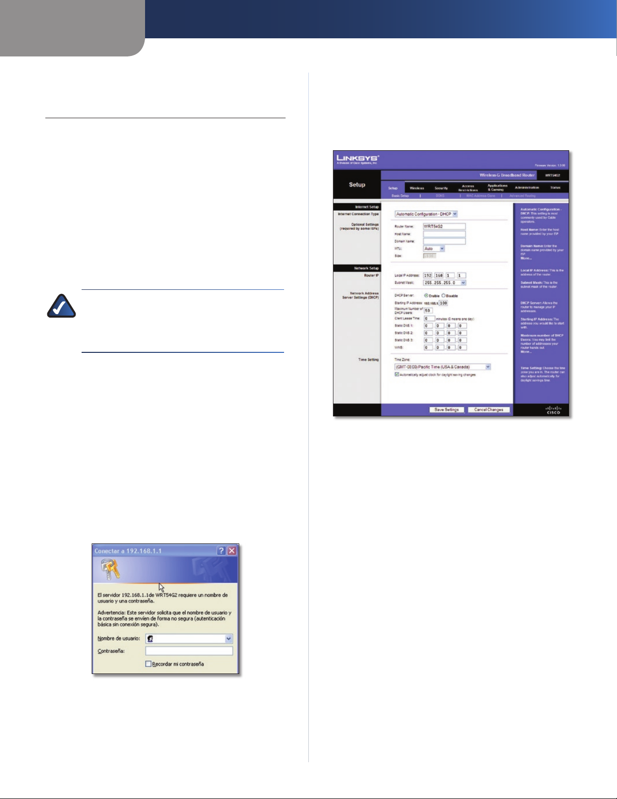
Capítulo 3
Configuración avanzada
Capítulo 3: Configuración avanzada
Después de configurar el router con el asistente de
configuración (ubicado en el CD-ROM), el router estará
listo para utilizarse. Sin embargo, si desea modificar los
parámetros avanzados, utilice la utilidad basada en web del
router. En este capítulo se describen las páginas web de la
utilidad y las funciones clave de cada una. Puede acceder a la
utilidad mediante un explorador web en una computadora
conectado al router.
La utilidad basada en web cuenta con las siguientes fichas
principales: Setup (Configuración), Wireless (Inalámbrico),
Security (Seguridad), Access Restrictions (Restricciones de
acceso), Applications & Gaming (Aplicaciones y juegos),
Administration (Administración) y Status (Estado). Al hacer
clic en una de las fichas principales, aparecerán fichas
adicionales.
NOTA: Al instalar por primera vez el router, deberá
utilizar el CD-ROM del asistente de configuración. Si
desea configurar los parámetros avanzados, utilice
este capítulo para obtener información sobre la
utilidad basada en web.
Setup > Basic Setup (Configuración > Configuración básica)
La primera pantalla que aparece es Basic Setup (Configuración
básica). Permite cambiar los parámetros generales del
router.
Cómo acceder a la utilidad basada en web
Para acceder a la utilidad basada en web, inicie el explorador
web en la computadora e introduzca la dirección IP
predeterminada del router, 192.168.1.1, en el campo
Dirección. A continuación, pulse Intro.
Aparece una pantalla en la que se le solicita una contraseña.
(Si no es usuario de Windows XP, verá una pantalla parecida).
Deje el campo Nombre de usuario en blanco. A continuación,
introduzca la contraseña establecida durante la ejecución del
asistente de configuración. Si no ha ejecutado el asistente
de configuración, utilice la contraseña predeterminada,
admin. Puede establecer una nueva contraseña en la ficha
Administration (Administración) de la pantalla Management
(Gestión). Haga clic en OK (Aceptar) para continuar.
Pantalla de la contraseña
Setup > Basic Setup (Configuración > Configuración básica)
Internet Setup (Configuración de Internet)
En la sección Internet Setup (Configuración de Internet) se
configura el router para la conexión a Internet. La mayor
parte de esta información se puede obtener del proveedor
de servicios de Internet (ISP).
Internet Connection Type (Tipo de conexión a Internet)
Seleccione el tipo de conexión a Internet que proporcione el
ISP en el menú desplegable. Los tipos disponibles son:
•
Automatic Configuration - DHCP (Configuración
automática - DHCP)
•
Static IP (IP estática)
PPPoE •
PPTP •
L2TP •
Telstra Cable •
Automatic Configuration - DHCP (Configuración automática DHCP)
El tipo de conexión a Internet predeterminado es Automatic
Configuration - DHCP (Configuración automática - DHCP).
Mantenga el tipo predeterminado sólo si su ISP admite
DHCP o si la conexión se va a realizar mediante una dirección
IP dinámica. (Esta opción se aplica normalmente a las
conexiones por cable.)
Router de banda ancha Wireless-G
4
Page 63
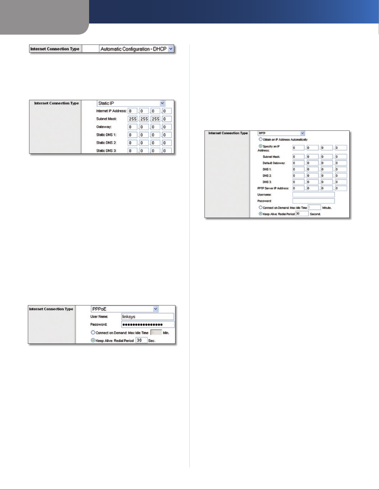
Capítulo 3
Internet Connection Type > Automatic Configuration - DHCP (Tipo de
conexión a Internet > Configuración automática - DHCP)
Static IP (IP estática)
Si necesita utilizar una dirección IP permanente para
conectarse a Internet, seleccione Static IP (IP estática).
Configuración avanzada
Keep Alive: Redial Period (Mantener activo: Periodo
para nueva marcación) Si selecciona esta opción, el router
comprobará periódicamente la conexión a Internet. Si se
desconecta, el router restablecerá automáticamente la
conexión. Para utilizar esta opción, seleccione Keep Alive
(Mantener activo). En el campo Redial Period (Periodo para
nueva marcación) especifique la frecuencia con que desea
que el router compruebe la conexión a Internet. El valor
predeterminado es 30 segundos.
PPTP
El protocolo de túnel de punto a punto (PPTP) es un servicio
que se utiliza únicamente en conexiones europeas.
Internet Connection Type > Static IP (Tipo de conexión a Internet > IP
estática)
Internet IP Address (Dirección IP de Internet) Se trata
de la dirección IP del router, vista desde Internet. El ISP le
proporcionará la dirección IP que debe especificar.
Subnet Mask (Máscara de subred) Se trata de la máscara
de subred del router, tal como la ven los usuarios en Internet
(incluido el ISP). El ISP le proporcionará la máscara de
subred.
Gateway El ISP le proporcionará la dirección del gateway,
que es la dirección IP del servidor del ISP.
Static DNS (DNS estático) El ISP le proporcionará al menos
una dirección IP de servidor DNS (sistema de nombres de
dominio).
PPPoE
Algunos ISP basados en DSL utilizan PPPoE (protocolo de
punto a punto en Ethernet) para establecer conexiones a
Internet. Si se conecta a Internet a través de una línea DSL,
consulte con el ISP si utiliza PPPoE. En ese caso, tendrá que
activar PPPoE.
Internet Connection Type (Tipo de conexión a Internet) > PPPoE
User Name y Password (Nombre de usuario y Contraseña)
Introduzca el nombre de usuario y la contraseña
proporcionados por el ISP.
Connect on Demand: Max Idle Time (Conectar cuando se
solicite: Tiempo máximo de inactividad) Puede configurar el
router para que interrumpa la conexión a Internet cuando
esté inactiva durante un periodo de tiempo especificado (Max
Idle Time [Tiempo máximo de inactividad]). Si la conexión a
Internet finaliza debido a la inactividad, Connect on Demand
(Conectar cuando se solicite) permite al router restablecer
automáticamente la conexión si intenta acceder de nuevo
a Internet. Para utilizar esta opción, seleccione Connect on
Demand (Conectar cuando se solicite). En el campo Max Idle
Time (Tiempo máximo de inactividad), introduzca el número
de minutos que desea que transcurran para que finalice la
conexión a Internet. El valor predeterminado es 5 minutos.
Internet Connection Type (Tipo de conexión a Internet) > PPTP
Si su ISP admite DHCP o si la conexión se realiza mediante
una dirección IP dinámica, seleccione Obtain an IP Address
Automatically (Obtener una dirección IP automáticamente).
Si necesita utilizar una dirección IP permanente para
conectarse a Internet, seleccione Specify an IP Address
(Especificar una dirección IP). A continuación, realice las
siguientes configuraciones:
• (Especificar una dirección IP) Se
Specify an IP Address
trata de la dirección IP del router, vista desde Internet. El
ISP le proporcionará la dirección IP que debe especificar.
• (Máscara de subred) Se trata de la máscara
Subnet Mask
de subred del router, tal como la ven los usuarios en
Internet (incluido el ISP). El ISP le proporcionará la máscara
de subred.
• (Gateway predeterminado) Su ISP le
Default Gateway
proporcionará la dirección IP del servidor ISP.
• El ISP le proporcionará al menos una dirección
DNS 1-3
IP de servidor DNS (sistema de nombres de dominio).
PPTP Server IP Address (Dirección IP del servidor PPTP) Su
ISP le proporcionará la dirección IP del servidor PPTP.
User Name y Password (Nombre de usuario y Contraseña)
Introduzca el nombre de usuario y la contraseña
proporcionados por el ISP.
Connect on Demand: Max Idle Time (Conectar cuando se
solicite: Tiempo máximo de inactividad) Puede configurar el
router para que interrumpa la conexión a Internet cuando
esté inactiva durante un periodo de tiempo especificado (Max
Idle Time [Tiempo máximo de inactividad]). Si la conexión a
Internet finaliza debido a la inactividad, Connect on Demand
(Conectar cuando se solicite) permite al router restablecer
automáticamente la conexión si intenta acceder de nuevo
a Internet. Para utilizar esta opción, seleccione Connect on
Demand (Conectar cuando se solicite). En el campo Max Idle
Time (Tiempo máximo de inactividad), introduzca el número
Router de banda ancha Wireless-G
5
Page 64

Capítulo 3
de minutos que desea que transcurran para que finalice la
conexión a Internet. El valor predeterminado es 5 minutos.
Keep Alive: Redial Period (Mantener activo: Periodo
para nueva marcación)
comprobará periódicamente la conexión a Internet. Si se
desconecta, el router restablecerá automáticamente la
conexión. Para utilizar esta opción, seleccione
(Mantener activo). En el campo Redial Period (Periodo para
nueva marcación) especifique la frecuencia con que desea
que el router compruebe la conexión a Internet. El valor
predeterminado es 30 segundos.
L2TP
L2TP es un servicio que se utiliza únicamente en conexiones
en Israel.
Internet Connection Type (Tipo de conexión a Internet) > L2TP
User Name y Password (Nombre de usuario y Contraseña)
Introduzca el nombre de usuario y la contraseña
proporcionados por el ISP.
L2TP Server (Servidor L2TP) Ésta es la dirección IP del
servidor L2TP. El ISP le proporcionará la dirección IP que debe
especificar.
Connect on Demand: Max Idle Time (Conectar cuando se
solicite: Tiempo máximo de inactividad) Puede configurar el
router para que interrumpa la conexión a Internet cuando
esté inactiva durante un periodo de tiempo especificado (Max
Idle Time [Tiempo máximo de inactividad]). Si la conexión a
Internet finaliza debido a la inactividad, Connect on Demand
(Conectar cuando se solicite) permite al router restablecer
automáticamente la conexión si intenta acceder de nuevo
a Internet. Para utilizar esta opción, seleccione Connect on
Demand (Conectar cuando se solicite). En el campo Max Idle
Time (Tiempo máximo de inactividad), introduzca el número
de minutos que desea que transcurran para que finalice la
conexión a Internet. El valor predeterminado es 5 minutos.
Keep Alive: Redial Period (Mantener activo: Periodo
para nueva marcación) Si selecciona esta opción, el router
comprobará periódicamente la conexión a Internet. Si se
desconecta, el router restablecerá automáticamente la
conexión. Para utilizar esta opción, seleccione Keep Alive
(Mantener activo). En el campo Redial Period (Periodo para
nueva marcación) especifique la frecuencia con que desea
que el router compruebe la conexión a Internet. El valor
predeterminado es 30 segundos.
Telstra Cable
Telstra Cable es un servicio que se utiliza únicamente en las
conexiones australianas. Si el ISP utiliza HeartBeat Signal
(HBS), seleccione Telstra Cable (Conexión por cable de
Telstra).
Si selecciona esta opción, el router
Keep Alive
Configuración avanzada
Internet Connection Type (Tipo de conexión a Internet) > Telstra Cable
User Name y Password (Nombre de usuario y Contraseña)
Introduzca el nombre de usuario y la contraseña
proporcionados por el ISP.
Heart Beat Server (Servidor de Heart Beat) Ésta es la
dirección IP del servidor de Heart Beat. El ISP le proporcionará
la dirección IP que debe especificar.
Connect on Demand: Max Idle Time (Conectar cuando se
solicite: Tiempo máximo de inactividad) Puede configurar el
router para que interrumpa la conexión a Internet cuando
esté inactiva durante un periodo de tiempo especificado (Max
Idle Time [Tiempo máximo de inactividad]). Si la conexión a
Internet finaliza debido a la inactividad, Connect on Demand
(Conectar cuando se solicite) permite al router restablecer
automáticamente la conexión si intenta acceder de nuevo
a Internet. Para utilizar esta opción, seleccione Connect on
Demand (Conectar cuando se solicite). En el campo Max Idle
Time (Tiempo máximo de inactividad), introduzca el número
de minutos que desea que transcurran para que finalice la
conexión a Internet. El valor predeterminado es 5 minutos.
Keep Alive: Redial Period (Mantener activo: Periodo
para nueva marcación) Si selecciona esta opción, el router
comprobará periódicamente la conexión a Internet. Si se
desconecta, el router restablecerá automáticamente la
conexión. Para utilizar esta opción, seleccione Keep Alive
(Mantener activo). En el campo Redial Period (Periodo para
nueva marcación) especifique la frecuencia con que desea
que el router compruebe la conexión a Internet. El valor
predeterminado es 30 segundos.
Parámetros opcionales
Es posible que el ISP exija el uso de algunos de estos
parámetros. Verifique con el ISP si es necesario realizar algún
cambio.
Optional Settings (Parámetros opcionales)
Router Name (Nombre de router) En este campo puede
introducir un nombre de hasta 39 caracteres para representar
el router.
Host Name/Domain Name (Nombre de host/Nombre de
dominio) En estos campos puede proporcionar un nombre de
host y de dominio para el router. Algunos ISP, normalmente
los de cable, solicitan estos nombres como identificación.
Puede que deba consultar al ISP si el servicio de Internet
de banda ancha se ha configurado con un nombre de host
y de dominio. En la mayoría de los casos, no habrá ningún
problema si se dejan estos campos en blanco.
Router de banda ancha Wireless-G
6
Page 65

Capítulo 3
Configuración avanzada
MTU MTU es la unidad de transmisión máxima. Especifica el
tamaño máximo de paquete permitido para la transmisión de
Internet. Seleccione Manual si desea introducir manualmente
el tamaño máximo de paquete que se transmitirá. Para que el
router seleccione la MTU óptima para la conexión a Internet,
mantenga el parámetro predeterminado Auto (Automático).
Size (Tamaño) Esta opción está habilitada cuando se
selecciona Manual en el campo MTU. Este valor debe estar
comprendido entre 1200 y 1500. El tamaño predeterminado
depende del tipo de conexión a Internet:
• 1500
DHCP, IP estática o Telstra:
• 1492
PPPoE:
• 1460
PPTP o L2TP:
Network Setup (Configuración de red)
La sección Network Setup (Configuración de red) permite
cambiar los parámetros de la red conectada a los puertos
Ethernet del router. La configuración inalámbrica se realiza
mediante la ficha Wireless (Inalámbrico).
Router IP (IP del router)
Muestra la dirección IP y la máscara de subred del router tal y
como las ve la red.
Maximum Number of DHCP Users (Número máximo de
usuarios de DHCP) Introduzca el número máximo de PC a los
que desea que el servidor DHCP asigne direcciones IP. Este
número no puede ser superior a 253. El valor predeterminado
es 50.
Client Lease Time (Tiempo de concesión del cliente) El
tiempo de concesión del cliente es la cantidad de tiempo que
un usuario podrá estar conectado al router con la dirección IP
dinámica actual. Introduzca el tiempo, en minutos, durante el
que se “concederá” al usuario esta dirección IP dinámica. Una
vez transcurrido este tiempo, se le asignará automáticamente
una nueva dirección IP dinámica al usuario o se le renovará
la concesión. El valor predeterminado es 0 minutos, lo que
significa un día.
Static DNS
dominio (DNS) es el método que se utiliza en Internet para
traducir los nombres de dominio o sitio web en direcciones
de Internet o URL. El ISP le proporcionará al menos una
dirección IP de servidor DNS. Si desea utilizar otra, introduzca
dicha dirección IP en uno de estos campos. Puede introducir
aquí hasta tres direcciones IP de servidor DNS. El router las
utilizará para acceder más rápidamente a los servidores DNS
en funcionamiento.
WINS El servicio de nombres de Internet de Windows (WINS)
administra la interacción de cada PC con Internet. Si va a
utilizar un servidor WINS, introduzca aquí la dirección IP del
mismo. De lo contrario, deje los campos en blanco.
(DNS estático)
(1-3)
El sistema de nombres de
Router IP Address (Dirección IP del router)
Network Address Server Settings (DHCP) [Parámetros de
servidor de direcciones de red (DHCP)]
Los parámetros le permiten configurar la función de servidor
de protocolo de configuración dinámica de host (DHCP)
del router. El router se puede utilizar como servidor DHCP
para la red. Un servidor DHCP asigna automáticamente una
dirección IP a cada computadora de la red. Si desea activar la
opción de servidor DHCP del router, asegúrese de que no hay
otro servidor DHCP en la red.
Network Address Server Settings (DHCP) [Parámetros de servidor de
DHCP Server (Servidor DHCP) DHCP viene activado de
fábrica, de forma predeterminada. Si ya dispone de un
servidor DHCP en la red o si no desea utilizar un servidor DHCP,
seleccione Disable (Desactivar) (no estarán disponibles otras
funciones de DHCP).
Starting IP Address (Dirección IP inicial) Introduzca un
valor para el servidor DHCP con el que se empezarán em
direcciones IP. Debido a que la dirección IP predeterminada
del router es 192.168.1.1, la dirección IP inicial debe ser
192.168.1.2 o mayor, pero menor que 192.168.1.253. El valor
predeterminado es 192.168.1.100
direcciones de red (DHCP)]
itir
.
Time Setting (Parámetro de hora)
Seleccione la zona horaria en la que funciona la red, en el menú
desplegable. (Puede incluso ajustarla automáticamente para
el horario de verano.)
Time Setting (Parámetro de hora)
Haga clic en Save Settings (Guardar parámetros) para guardar
los cambios o en Cancel Changes (Cancelar cambios) para
eliminarlos.
Setup (Configuración) > DDNS
El router proporciona una función de sistema dinámico de
nombres de dominio (DDNS). DDNS permite asignar un
nombre de host y de dominio fijo a una dirección IP dinámica
de Internet. Así podrá alojar su propio sitio web, servidor FTP
u otro servidor que se encuentre detrás del router.
Para poder utilizar esta función, debe suscribirse al s
www.dyndns.org o www.TZO.com. Si no desea utilizar esta
función, mantenga el parámetro predeterminado, Disable
(Desactivar).
DDNS
El router proporciona una función de sistema dinámico de
nombres de dominio (DDNS). DDNS permite asignar un
nombre de host y de dominio fijo a una dirección IP dinámica
de Internet. Así podrá alojar su propio sitio web, servidor FTP
u otro servidor que se encuentre detrás del router.
Router de banda ancha Wireless-G
7
Page 66

Capítulo 3
Configuración avanzada
Para poder utilizar esta función debe suscribirse al servicio
DDNS con uno de los distribuidores de dicho servicio,
DynDNS.org o TZO.com. Si no desea utilizar esta función,
mantenga el valor predeterminado Disable (Desactivar).
DDNS Service (Servicio DDNS)
Si DynDNS.org proporciona el servicio DDNS, seleccione
DynDNS.org en el menú desplegable. Si TZO proporciona
el servicio DDNS, seleccione TZO.com. Las funciones
disponibles en la pantalla DDNS varían según el proveedor
del servicio DDNS que utilice.
DynDNS.org
Setup (Configuración) > DDNS > DynDNS
E-mail Address (Correo electrónico), TZO Key (Clave de
TZO) y Domain Name (Nombre de dominio) Introduzca los
parámetros de la cuenta que haya configurado en TZO.
Internet IP Address (Dirección IP de Internet) Se muestra la
dirección IP de Internet del router. Esta dirección cambiará,
ya que es dinámica.
Status (Estado) Se muestra el estado de la conexión del
servicio DDNS.
Haga clic en Save Settings (Guardar parámetros) para guardar
los cambios o en Cancel Changes (Cancelar cambios) para
eliminarlos.
Setup > MAC Address Clone (Configuración > Clonación de direcciones MAC)
Algunos ISP requieren que se registre una dirección MAC
para acceder a Internet. Una dirección MAC es un código
de 12 dígitos asignado a un dispositivo de hardware para
su identificación. Si no desea volver a registrar la dirección
MAC con el ISP, puede utilizar la función MAC Address Clone
(Clonación de dirección MAC) para asignar al router la
dirección MAC actualmente registrada.
User Name (Nombre de usuario) Introduzca el nombre de
usuario de la cuenta DDNS.
Password (Contraseña) Introduzca la contraseña de la
cuenta DDNS.
Host Name (Nombre de host) Se trata de la dirección URL de
DDNS asignada por el servicio DDNS.
Internet IP Address (Dirección IP de Internet) Se muestra la
dirección IP de Internet del router. Esta dirección cambiará,
ya que es dinámica.
Status (Estado) Se muestra el estado de la conexión del
servicio DDNS.
Haga clic en Save Settings (Guardar parámetros) para guardar
los cambios o en Cancel Changes (Cancelar cambios) para
eliminarlos.
TZO.com
Setup > MAC Address Clone (Configuración > Clonación de direcciones
MAC)
MAC Address Clone (Clonación de direcciones
MAC)
Enable/Disable (Activar/Desactivar) Para que se clone la
dirección MAC, seleccione Enable (Activar).
User Defined Entry (Entrada definida por el usuario)
Introduzca aquí la dirección MAC registrada con el ISP.
Clone Your PC’s MAC (Clonar la MAC del PC) Al hacer clic en
este botón se clonará la dirección MAC de la computadora
que esté utilizando.
Haga clic en Save Settings (Guardar parámetros) para guardar
los cambios o en Cancel Changes (Cancelar cambios) para
eliminarlos.
Setup > Advanced Routing (Configuración
Setup (Configuración) > DDNS > TZO
Router de banda ancha Wireless-G
> Enrutamiento avanzado)
Esta pantalla se utiliza para configurar las funciones avanzadas
de enrutamiento del router. NAT (Traducción de direcciones
de red) dirige a Internet la conexión de red del router host.
Con Dynamic Routing (Enrutamiento dinámico), se ajusta
automáticamente el modo en que los paquetes recorren la
red. Con Enrutamiento estático se puede configurar una ruta
fija a otro destino de red.
8
Page 67

Capítulo 3
Setup > Advanced Routing (Configuración > Enrutamiento avanzado)
(Gateway)
Setup > Advanced Routing (Configuración > Enrutamiento avanzado)
(Router)
Configuración avanzada
Select set number (Seleccionar número configurado)
Para configurar una ruta estática entre el router y otra
red, seleccione un número en la lista desplegable Static
Routing (Enrutamiento estático). Una ruta estática es la ruta
predeterminada por la que se desplaza la información de
red hasta alcanzar un host determinado o una red concreta.
Introduzca la información descrita a continuación para
configurar una nueva ruta estática. Haga clic en el botón
Delete This Entry (Eliminar esta entrada) para eliminar una
ruta estática.
Enter Route Name (Introducir nombre de ruta) Introduzca
aquí el nombre de la ruta, con un máximo de 25 caracteres
alfanuméricos.
Destination LAN IP (IP de red LAN de destino) La IP de la red
LAN de destino es la dirección de la red o el host remoto al
que desea asignar una ruta estática.
Subnet Mask (Máscara de subred) La máscara de subred
determina qué parte de una dirección IP de red LAN de
destino corresponde a la parte de la red y cuál a la parte del
host.
Default Gateway (Gateway predeterminado) Se trata de
la dirección IP del dispositivo de gateway que permite el
contacto entre el router y la red o el host remoto.
Interface (Interfaz) Esta interfaz indica si la dirección IP de
destino está en LAN & Wireless (Red LAN e inalámbrica)
(para redes Ethernet e inalámbricas) o WAN (Internet).
Delete This Entry (Eliminar esta entrada) Para eliminar una
ruta, seleccione su número en el menú desplegable y haga
clic en este botón.
Show Routing Table (Mostrar tabla de enrutamiento) Haga
clic en el botón Show Routing Table (Mostrar tabla de
enrutamiento) para abrir una pantalla en la que se mostrará
cómo se enrutan los datos a través de la red local. Para cada
ruta se muestran la dirección IP de red LAN de destino, la
máscara de subred, el gateway y la interfaz. Haga clic en
Refresh (Actualizar) para actualizar la información. Haga clic
en Close (Cerrar) para salir de esta pantalla.
Advanced Routing (Enrutamiento avanzado)
Operating Mode (Modo de funcionamiento) Seleccione
el modo en que funcionará este router. Si el router aloja la
conexión a Internet de la red, seleccione Gateway. Si existe
otro router en la red, seleccione Router. Al seleccionar el
router, la opción Dynamic Routing (Enrutamiento dinámico)
estará disponible.
Dynamic Routing (Enrutamiento dinámico)
RIP Esta función permite que el router se ajuste
automáticamente a los cambios físicos que se produzcan en
el diseño de la red e intercambie tablas de enrutamiento con
el resto de routers. El router determina la ruta de los paquetes
de red basándose en el menor número de saltos entre el
origen y el destino. El valor predeterminado de esta función
es Disabled (Desactivado). En el menú desplegable también
puede seleccionar LAN & Wireless (Red LAN e inalámbrica),
que realiza un enrutamiento dinámico por las redes Ethernet
e inalámbrica. También puede seleccionar WAN (Internet),
que realiza un enrutamiento dinámico con los datos
procedentes de Internet. Finalmente, al seleccionar Both
(Ambas) se permite el enrutamiento dinámico para ambas
redes, así como para los datos procedentes de Internet.
Router de banda ancha Wireless-G
Tabla de enrutamiento
Haga clic en Save Settings (Guardar parámetros) para guardar
los cambios o en Cancel Changes (Cancelar cambios) para
eliminarlos.
Wireless > Basic Wireless Settings (Inalámbrico > Parámetros inalámbricos básicos)
Los parámetros básicos para la red inalámbrica se establecen
en esta pantalla.
Hay dos formas de configurar las redes inalámbricas del
router: De forma manual y mediante la configuración Wi-Fi
protegida.
9
Page 68

Capítulo 3
Configuración avanzada
Esta última facilita la configuración de la red inalámbrica.
Si dispone de dispositivos cliente, como adaptadores
inalámbricos, que sean compatibles con la configuración WiFi protegida, podrá utilizar este tipo de configuración.
Inalámbrico > Parámetros inalámbricos básicos: Configuración manual
Wireless Configuration (Configuración inalámbrica) Para
configurar la red inalámbrica de forma manual, seleccione
Manual. Vaya a la sección “Wireless Network (Red inalámbrica)
(Manual)”. Para utilizar la configuración Wi-Fi protegida,
seleccione Wi-Fi Protected Setup (Configuración Wi-Fi
protegida). Consulte Wi-Fi Protected Setup (Configuración
Wi-Fi protegida) en la página 10.
Wireless Network (Red inalámbrica) (Manual)
Wi-Fi Protected Setup (Configuración Wi-Fi
protegida)
Hay tres métodos disponibles. Utilice el método que
corresponda al dispositivo cliente que está configurando.
Wireless > Basic Wireless Settings: Wi-Fi Protected Setup (Inalámbrico >
Parámetros inalámbricos básicos: Configuración Wi-Fi protegida)
Wireless Network Mode (Modo de red inalámbrica) En
este menú desplegable puede seleccionar los estándares
inalámbricos que se utilizan en la red. Si cuenta con dispositivos
Wireless-N, Wireless-G y Wireless-B en la red, mantenga el
parámetro predeterminado, Mixed (Mixto). Si sólo dispone
de dispositivos Wireless-G y Wireless-B en la red, seleccione
BG-Mixed (Mixto BG). Si sólo dispone de dispositivos
Wireless-N, seleccione Wireless-B Only (Sólo Wireless-N).
Si sólo tiene dispositivos Wireless-G, seleccione Wireless-G
Only (Sólo Wireless-G). Si sólo tiene dispositivos Wireless-B,
seleccione Wireless-B Only (Sólo Wireless-B). Si la red no
tiene ningún dispositivo inalámbrico, o si desea desactivar la
red inalámbrica, seleccione Disabled (Desactivado).
Wireless Network Name (SSID) (Nombre de la red
inalámbrica, SSID) El SSID es un nombre de red que
comparten todos los dispositivos de una red inalámbrica.
Debe ser el mismo para todos los dispositivos de la red
inalámbrica. El nombre distingue entre mayúsculas y
minúsculas y no debe tener una longitud superior a los
32 caracteres. Para mayor seguridad, debe cambiar el SSID
predeterminado (linksys) por otro que sea exclusivo.
Wireless Channel (Canal inalámbrico) Seleccione el canal
de la lista que coincida con los parámetros de red. Para que
el funcionamiento sea correcto, debe realizarse la difusión
para todos los dispositivos de la red inalámbrica en el mismo
canal.
Wireless SSID Broadcast (Difusión inalámbrica de SSID)
Cuando los clientes inalámbricos sondeen el área local
en busca de redes inalámbricas con las que asociarse,
detectarán el SSID que difunde el router. Para difundir el
SSID del router, mantenga el parámetro predeterminado
Enabled (Activado). Si no desea difundir el SSID del router,
seleccione Disabled (Desactivado).
Haga clic en Save Settings (Guardar parámetros) para guardar
los cambios o en Cancel Changes (Cancelar cambios) para
eliminarlos.
Wi-Fi Protected Setup > Congratulations (Configuración Wi-Fi protegida
> Enhorabuena)
NOTA: La configuración Wi-Fi protegida configura
los dispositivos cliente de uno en uno. Repita las
instrucciones para cada dispositivo cliente que sea
compatible con la configuración Wi-Fi protegida.
Método n.º 1
Utilice este método si el dispositivo cliente cuenta con un
botón Wi-Fi Protected Setup (Configuración Wi-Fi protegida).
Haga clic o pulse el botón 1. Wi-Fi Protected Setup
(Configuración Wi-Fi protegida) del dispositivo cliente.
Haga clic en el botón 2. Wi-Fi Protected Setup
(Configuración Wi-Fi protegida) que aparece en esta
pantalla.
Router de banda ancha Wireless-G
10
Page 69

Capítulo 3
Configuración avanzada
Una vez que el dispositivo cliente se haya configurado, 3.
haga clic en OK (Aceptar). A continuación, vuelva al
dispositivo cliente o consulte la documentación para
obtener más instrucciones.
Método n.º 2
Utilice este método si el dispositivo cliente cuenta con un
número PIN de configuración Wi-Fi protegida.
Introduzca el número PIN en el1. campo que aparece en
esta pantalla.
Haga clic en 2. Register (Registro).
Una vez que el dispositivo cliente se haya configurado, 3.
haga clic en OK (Aceptar). A continuación, vuelva al
dispositivo cliente o consulte la documentación para
obtener más instrucciones.
Método n.º 3
Utilice este método si el dispositivo cliente solicita el número
PIN del router.
Introduzca el número PIN que aparece en esta pantalla. 1.
(También aparece en la etiqueta que hay en la parte
inferior del router).
Una vez que el dispositivo cliente se haya configurado, 2.
haga clic en OK (Aceptar). A continuación, vuelva al
dispositivo cliente o consulte la documentación para
obtener más instrucciones.
En la parte inferior de la pantalla aparecen las opciones
Wi-Fi Protected Setup Status (Estado de la configuración
Wi-Fi protegida), Network Name (SSID) (Nombre de la red,
SSID), Security (Seguridad), Encryption (Encriptación) y
Passphrase (Frase de paso).
NOTA: Si dispone de dispositivos cliente que
no son compatibles con la configuración Wi-Fi
protegida, anote los parámetros inalámbricos y, a
continuación, configure los dispositivos cliente de
forma manual.
Security Mode (Modo de seguridad)
Seleccione el método de seguridad para la red inalámbrica.
Si no desea utilizar la seguridad inalámbrica, mantenga el
parámetro predeterminado Disabled (Desactivado).
WPA2 Personal
NOTA: Si utiliza WPA2 o WPA, cada dispositivo de
la red inalámbrica DEBE utilizar el mismo método
WPA y la misma clave compartida; de lo contrario,
la red no funcionará correctamente.
Security Mode (Modo de seguridad) > WPA2 Personal
WPA Algorithm (Algoritmo WPA) WPA2 admite dos métodos
de encriptación, TKIP y AES, con claves de encriptación
dinámica. Seleccione el tipo de algoritmo, AES o TKIP + AES.
El nombre predeterminado es AES.
WPA Shared Key (Clave compartida WPA) Introduzca una
clave compartida WPA que contenga de 8 a 63 caracteres.
Group Key Renewal (Renovación de clave de grupo)
Introduzca un periodo de renovación de clave de grupo,
que indica al router la frecuencia con que debe cambiar las
claves de encriptación. El valor predeterminado es 3.600
segundos.
Wireless > Wireless Security (Inalámbrico > Seguridad inalámbrica)
Los parámetros de la ficha Wireless Security (Seguridad
inalámbrica) configuran la seguridad de la red inalámbrica.
El router admite seis opciones de modo de seguridad
inalámbrica: WPA2 Personal, WPA Personal, WPA2 Enterprise,
WPA Enterprise, RADIUS, y WEP. WPA (acceso Wi-Fi protegido)
es un estándar de seguridad más fiable que WEP (privacidad
equivalente a conexión con cables), y WPA2 es incluso más
seguro que WPA. RADIUS son las siglas en inglés para "servicio
de usuario de acceso telefónico de autenticación remota".
Estas seis opciones se analizan a continuación. Para obtener
más información sobre seguridad inalámbrica, consulte
el Capítulo 2: Lista de comprobación de seguridad
inalámbrica en la página 3.
Wireless Security (Seguridad inalámbrica)
Se recomienda encarecidamente el uso de seguridad
inalámbrica. WPA2 es el método más fiable. Utilice WPA2 si es
compatible con todos sus dispositivos inalámbricos.
Router de banda ancha Wireless-G
WPA Personal
NOTA: Si utiliza WPA2 o WPA, cada dispositivo de
la red inalámbrica DEBE utilizar el mismo método
WPA y la misma clave compartida; de lo contrario,
la red no funcionará correctamente.
Security Mode (Modo de seguridad) > WPA Personal
11
Page 70

Capítulo 3
WPA Algorithm (Algoritmo WPA) WPA admite dos métodos
de encriptación, TKIP y AES, con claves de encriptación
dinámica. Seleccione el tipo de algoritmo, TKIP o AES. (AES
es un método de encriptación más seguro que TKIP.)
WPA Shared Key (Clave compartida WPA) Introduzca la
clave compartida por el router y el resto de dispositivos de
red. Debe tener entre 8 y 63 caracteres.
Group Key Renewal (Renovación de clave de grupo)
Introduzca un periodo de renovación de clave, que indica
al router la frecuencia con que debe cambiar las claves de
encriptación. El valor predeterminado es 3.600 segundos.
WPA2 Enterprise
Esta opción permite el uso de WPA2 junto con un servidor
RADIUS. (Sólo se debe utilizar si hay un servidor RADIUS
conectado al router.)
Security Mode (Modo de seguridad) > WPA2 Enterprise
WPA Algorithm (Algoritmo WPA) WPA2 admite dos métodos
de encriptación, TKIP y AES, con claves de encriptación
dinámica. Seleccione el tipo de algoritmo, AES o TKIP + AES.
El nombre predeterminado es AES.
RADIUS Server Address (Dirección de servidor RADIUS)
Introduzca la dirección IP del servidor RADIUS.
RADIUS Port (Puerto RADIUS) Introduzca el número de
puerto del servidor RADIUS. El valor predeterminado es
1812.
Shared Key (Clave compartida) Introduzca la clave
compartida entre el router y el servidor.
Key Renewal Timeout (Tiempo de espera de renovación
de claves) Introduzca un periodo de renovación de claves
que indique al router la frecuencia con que debe cambiar
las claves de encriptación. El valor predeterminado es 3.600
segundos.
Configuración avanzada
Security Mode (Modo de seguridad) > WPA Enterprise
WPA Algorithm (Algoritmo WPA) WPA admite dos métodos
de encriptación, TKIP y AES, con claves de encriptación
dinámica. Seleccione el tipo de algoritmo, TKIP o AES. (AES
es un método de encriptación más seguro que TKIP.)
RADIUS Server Address (Dirección de servidor RADIUS)
Introduzca la dirección IP del servidor RADIUS.
RADIUS Port (Puerto RADIUS) Introduzca el número de
puerto del servidor RADIUS. El valor predeterminado es
1812.
Shared Key (Clave compartida) Introduzca la clave
compartida entre el router y el servidor.
Key Renewal Timeout (Tiempo de espera de renovación
de claves) Introduzca un periodo de renovación de claves
que indique al router la frecuencia con que debe cambiar
las claves de encriptación. El valor predeterminado es 3.600
segundos.
RADIUS
Esta opción permite el uso de WEP junto con un servidor
RADIUS (Sólo se debe utilizar si hay un servidor RADIUS
conectado al router).
WPA Enterprise
Esta opción permite el uso de WPA junto con un servidor
RADIUS. (Sólo se debe utilizar si hay un servidor RADIUS
conectado al router).
Router de banda ancha Wireless-G
Security Mode (Modo de seguridad) > RADIUS
IMPORTANTE: Si utiliza encriptación WEP, cada
dispositivo de la red inalámbrica DEBE utilizar el
mismo método de encriptación WEP y la misma clave
de encriptación; de lo contrario, la red inalámbrica no
funcionará correctamente.
12
Page 71

Capítulo 3
Configuración avanzada
RADIUS Server Address (Dirección de servidor RADIUS)
Introduzca la dirección IP del servidor RADIUS.
RADIUS Port (Puerto RADIUS) Introduzca el número de
puerto del servidor RADIUS. El valor predeterminado es
1812.
Shared Key (Clave compartida) Introduzca la clave
compartida entre el router y el servidor.
Default Transmit Key (Clave de transmisión
predeterminada) Seleccione una clave de transmisión
predeterminada (elija la que desea utilizar). El valor
predeterminado es 1.
WEP Encryption (Encriptación WEP) Seleccione un nivel
de cifrado WEP, 64 bits 10 hex digits (64 bits, 10 dígitos
hexadecimales) o 128 bits 26 hex digits (128 bits, 26 dígitos
hexadecimales). El valor predeterminado es 64 bits 10 hex
digits (64 bits, 10 dígitos hexadecimales).
Passphrase (Frase de paso) Introduzca una frase de paso para
generar las claves WEP de forma automática. A continuación,
haga clic en Generate (Generar).
Key 1-4 (Clave 1-4) Si no ha introducido ninguna frase de
paso, introduzca las claves WEP de forma manual.
WEP
WEP es un método de encriptación básico y no es tan seguro
como WPA.
Key 1-4 (Clave 1-4) Si no ha introducido ninguna frase de
paso, introduzca las claves WEP de forma manual.
Haga clic en Save Settings (Guardar parámetros) para guardar
los cambios o en Cancel Changes (Cancelar cambios) para
eliminarlos.
Wireless > Wireless MAC Filter (Inalámbrico > Filtro de MAC inalámbrico)
Se puede filtrar (restringir) el acceso inalámbrico si se
especifican las direcciones MAC de los dispositivos de la red
inalámbrica.
Wireless > Wireless MAC Filter (Inalámbrico > Filtro de MAC inalámbrico)
IMPORTANTE: Si utiliza encriptación WEP, cada
dispositivo de la red inalámbrica DEBE utilizar el
mismo método de encriptación WEP y la misma clave
de encriptación; de lo contrario, la red inalámbrica no
funcionará correctamente.
Security Mode (Modo de seguridad) > WEP
Default Transmit Key (Clave de transmisión predeterminada)
Seleccione una clave de transmisión predeterminada (elija la
que desea utilizar). El valor predeterminado es 1.
WEP Encryption (Encriptación WEP) Seleccione un nivel de
encriptación WEP, 64 bits 10 hex digits (64 bits, 10 dígitos
hexadecimales) o 128 bits 26 hex digits (128 bits, 26 dígitos
hexadecimales). El valor predeterminado es 64 bits 10 hex
digits (64 bits, 10 dígitos hexadecimales).
Passphrase (Frase de paso) Introduzca una frase de paso para
generar las claves WEP de forma automática. A continuación,
haga clic en Generate (Generar).
Wireless MAC Filter (Filtro de MAC inalámbrico)
Wireless MAC Filter (Filtro de MAC inalámbrico)
los usuarios por dirección MAC, ya sea para permitir o bloquear
el acceso, haga clic en Enable (Activar). Si no desea filtrar los
usuarios por la dirección MAC, mantenga el valor predeterminado
Disable
Prevent (Evitar) Selecciónelo para bloquear el acceso
inalámbrico por dirección MAC. Este botón está seleccionado
de forma predeterminada.
Permit Only (Permitir sólo) Selecciónelo para tener el
acceso inalámbrico por dirección MAC. Este botón no está
seleccionado de forma predeterminada.
Edit MAC Filter List (Editar lista de filtros de direcciones
MAC)
Address Filter List (Lista de filtros de direcciones MAC). En esta
pantalla se pueden enumerar por dirección MAC los usuarios a
los que desea proporcionar o bloquear el acceso. Para facilitar la
referencia, haga clic en Wireless Client MAC List (Lista de MAC
de clientes inalámbricos) para mostrar una lista de usuarios de la
red por dirección MAC
(Desactivar).
Haga clic en esta opción para abrir la pantalla MAC
.
Para filtrar
Router de banda ancha Wireless-G
13
Page 72
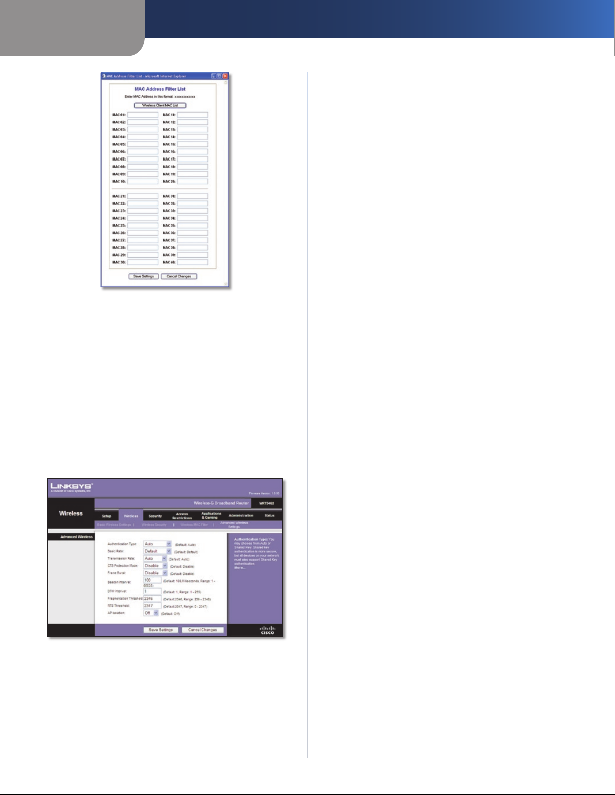
Capítulo 3
MAC Address Filter List (Lista de filtros de direcciones MAC)
Haga clic en Save Settings (Guardar parámetros) para guardar
los cambios o en Cancel Changes (Cancelar cambios) para
eliminarlos.
Wireless > Advanced Wireless Settings (Inalámbrico > Parámetros inalámbricos avanzados)
La pantalla Wireless > Advanced Wireless Settings (Inalámbrico
> Parámetros inalámbricos avanzados) se utiliza para
configurar las funciones inalámbricas avanzadas del router.
Estos parámetros sólo los debe ajustar un administrador
experto, ya que unos parámetros incorrectos pueden reducir
el rendimiento inalámbrico.
Wireless > Advanced Wireless Settings (Inalámbrico > Parámetros
inalámbricos avanzados)
Advanced Wireless (Parámetros inalámbricos
avanzados)
Authentication Type (Tipo de autenticación) El valor
predeterminado está establecido en Auto (Automático),
que permite utilizar la autenticación Open System
(Sistema abierto) o Shared Key (Clave compartida). Con la
Router de banda ancha Wireless-G
Configuración avanzada
autenticación Open System (Sistema abierto), el emisor y el
receptor NO utilizan una clave WEP para la autenticación. Con
la autenticación Shared Key (Clave compartida), el emisor y
el receptor utilizan una clave WEP para la autenticación.
Basic Rate (Velocidad básica) Este parámetro en realidad
no es una única velocidad de transmisión, sino una serie de
velocidades a las que puede transmitir el router. El router
anunciará su velocidad básica a los demás dispositivos
inalámbricos de la red para que conozcan las velocidades que
se utilizarán. El router también anunciará que seleccionará
automáticamente la mejor velocidad para la transmisión. El
parámetro predeterminado es Default (Predeterminada),
indicado para transmitir a todas las velocidades inalámbricas
estándar (1-2 Mbps, 5.5 Mbps, 1 Mbps, 18 Mbps y 24 Mbps).
Otras opciones son 1-2 Mbps (1-2 Mbps), indicada para
tecnología inalámbrica antigua, y All (Todas), para transmitir a
todas las velocidades inalámbricas. La velocidad básica no es
la velocidad real de transmisión de datos. Si desea especificar
la velocidad de transmisión de datos del router, configure el
parámetro Transmission Rate (Velocidad de transmisión).
Transmission Rate (Velocidad de transmisión) La velocidad
de transmisión de datos se debe establecer según la velocidad
de la red inalámbrica. Puede seleccionar un valor entre una
serie de velocidades de transmisión o bien seleccionar Auto
(Automática) para que el router utilice automáticamente la
máxima velocidad de transferencia de datos posible y active
la función de reserva automática. Dicha función negociará
la mejor velocidad de conexión posible entre el router y
un cliente inalámbrico. El valor predeterminado es Auto
(Automática).
CTS Protection Mode (Modo de protección CTS) El modo
de protección CTS (listo para emitir) debe permanecer
desactivado a menos que tenga problemas graves con los
productos Wireless-G y éstos no puedan transmitir al router
en un entorno con tráfico 802.11b intenso. Esta función
incrementa la capacidad del router para captar todas las
transmisiones Wireless-G, pero reduce el rendimiento en
gran medida.
Frame Burst (Ráfaga de tramas) Al activar esta opción se
debe conseguir un mayor rendimiento de la red, en función
del fabricante de los productos inalámbricos. Para activar la
opción Frame Burst (Ráfaga de tramas), seleccione Enable
(Activar). La opción predeterminada es Disable (Desactivar).
Beacon Interval (Intervalo de baliza) Una baliza consiste
en un paquete difundido por el router para sincronizar la
red inalámbrica. El valor predeterminado es 100. Introduzca
un valor entre 1 y 65.535 milisegundos. Este valor indica el
intervalo de frecuencia de la baliza.
DTIM Interval (Intervalo DTIM) Este valor, entre 1 y 255,
indica el intervalo de mensajes de indicación de tráfico
de entrega (DTIM). El campo DTIM es un campo de cuenta
atrás que informa a los clientes del siguiente intervalo para
la recepción de mensajes de difusión y multidifusión. Una
vez que el router ha almacenado en el búfer los mensajes de
difusión o multidifusión para los clientes asociados, envía el
siguiente DTIM con un valor de intervalo DTIM. Sus clientes
reciben las balizas y se activan para recibir los mensajes de
difusión y multidifusión. El valor predeterminado es 1.
Fragmentation Threshold (Umbral de fragmentación) Este
valor especifica el tamaño máximo de un paquete antes de
fragmentar los datos en varios paquetes. Si experimenta
una tasa alta de errores de paquete, puede aumentar
ligeramente el umbral de fragmentación. Si establece un
umbral de fragmentación demasiado bajo, se puede reducir
el rendimiento de la red. Sólo se recomiendan reducciones
14
Page 73

Capítulo 3
Configuración avanzada
mínimas del valor predeterminado. En la mayoría de los
casos, debe permanecer en su valor predeterminado, 2346.
RTS Threshold (Umbral RTS) Si detecta un flujo de datos
irregular, sólo se recomienda realizar una reducción mínima
del valor predeterminado, 2347. Si un paquete de red es
más pequeño que el tamaño de umbral RTS predefinido, el
mecanismo RTS/CTS no se activará. El router envía tramas
de petición de envío (RTS) a una determinada estación de
recepción y negocia el envío de una trama de datos. Después
de recibir una RTS, la estación inalámbrica responde con una
trama de listo para emitir (CTS) para confirmar el inicio de la
transmisión. El valor del umbral RTS debe permanecer en su
valor predeterminado, 2347.
AP Isolation (Aislamiento de PA) Este parámetro aísla entre sí
todos los clientes y los dispositivos inalámbricos de la red. Los
dispositivos inalámbricos se podrán comunicar con el router,
pero no entre ellos. Para utilizar esta función, seleccione On
(Activado). El aislamiento de PA está en Off (Desactivado) de
forma predeterminada.
Haga clic en Save Settings (Guardar parámetros) para guardar
los cambios o en Cancel Changes (Cancelar cambios) para
eliminarlos.
Security (Seguridad) > Firewall
La pantalla Security (Seguridad) > Firewall se utiliza para
configurar un firewall que pueda filtrar varios tipos de tráficos
no deseados en la red local del router.
Filter Internet NAT Redirection (Filtrar redirección NAT
de Internet) Esta función utiliza el reenvío de puertos
para bloquear el acceso a los servidores locales desde
computadoras en red locales. Seleccione
Redirection (Filtrar redirección NAT de Internet) para filtrar
la redirección NAT de Internet. Esta función está activada de
forma predeterminada.
Filter IDENT (Port 113) (Filtrar IDENT, Puerto 113) Esta
función impide que los dispositivos externos a la red local
analicen el puerto 113. Esta función está activada de forma
predeterminada. Desactive esta función para desactivarla.
Haga clic en Save Settings (Guardar parámetros) para guardar
los cambios o en Cancel Changes (Cancelar cambios) para
eliminarlos.
Filter Internet NAT
Security > VPN Passthrough (Seguridad > Paso a través de VPN)
La pantalla Security > VPN Passthrough (Seguridad > Paso a
través de VPN) le permite activar los túneles VPN que utilicen
los protocolos IPSec, PPTP o L2TP para pasar a través del
firewall del router.
Security (Seguridad) > Firewall
Firewall
Firewall Protection (Protección de firewall) Para utilizar la
protección de firewall, mantenga la selección predeterminada,
Enable (Activar). Para desactivar la protección de firewall,
seleccione Disable (Desactivar).
Block WAN Requests (Bloquear solicitudes WAN)
Block Anonymous Internet Requests (Bloquear
solicitudes anónimas de Internet) Esta función
dificulta a los usuarios externos el acceso a la red. Esta
función está seleccionada de forma predeterminada.
Desactive la función para permitir las solicitudes de Internet
anónimas
Filter Multicast (Filtrar multidifusión) Esta función permite
varias transmisiones simultáneas a receptores específicos. Si
activa la multidifusión, el router permitirá que los paquetes de
multidifusión IP se reenvíen a las computadoras adecuadas.
Esta función está activada de forma predeterminada. Desactive
esta función para desactivarla.
.
Security > VPN Passthrough (Seguridad > Paso a través de VPN)
VPN Passthrough (Paso a través de VPN)
IPSec Passthrough (Paso a través de IPSec) La seguridad de
protocolo de Internet (IPSec) es un conjunto de protocolos
utilizados para implantar el intercambio seguro de paquetes
en la capa IP. Para permitir que los túneles IPSec pasen a
través del router, mantenga el valor predeterminado Enable
(Activar).
PPTP Passthrough (Paso a través de PPTP) El protocolo de
túnel de punto a punto (PPTP) permite establecer túneles
para el protocolo de punto a punto (PPP) a través de una
red IP. Para permitir que los túneles PPTP pasen a través del
router, mantenga el valor predeterminado Enable (Activar).
L2TP Passthrough (Paso a través de L2TP) El protocolo de
túnel de capa 2 es el método que se utiliza para activar las
sesiones de punto a punto a través de Internet en el nivel de
capa 2. Para permitir que los túneles L2TP pasen a través del
router, mantenga el valor predeterminado Enable (Activar).
Haga clic en Save Settings (Guardar parámetros) para guardar
los cambios o en Cancel Changes (Cancelar cambios) para
eliminarlos.
Router de banda ancha Wireless-G
15
Page 74

Capítulo 3
Configuración avanzada
Access Restrictions > Internet Access (Restricciones de acceso > Acceso a Internet)
La pantalla Access Restrictions > Internet Access (Restricciones
de acceso > Acceso a Internet) permite bloquear o aceptar
determinados tipos de uso y tráfico de Internet, como
el acceso a Internet, servicios concretos y sitios web a
determinados días y horas.
Status (Estado) De forma predeterminada, las directivas
están desactivadas. Para activar una directiva, seleccione
su número en el menú desplegable y seleccione Enable
(Activar).
Para crear una directiva de acceso a Internet:
Seleccione un número en el menú desplegable 1. Internet
Access Policy (Directiva de acceso a Internet).
Para activar esta directiva, seleccione 2. Enable (Activar).
Introduzca un nombre de directiva en el campo 3.
proporcionado.
Haga clic en 4. Edit List of PCs (Editar lista de PC) para
seleccionar las computadoras a las que afectará esta
directiva. Aparecerá la pantalla List of PCs (Lista de PC).
Puede seleccionar un PC por dirección MAC o por dirección
IP. También puede introducir un intervalo de direcciones
IP si desea que esta directiva afecte a un grupo de PC.
Tras efectuar los cambios, haga clic en Save Settings
(Guardar parámetros) para aplicar los cambios, o bien
en Cancel Changes (Cancelar cambios) para borrarlos. A
continuación, haga clic en Close (Cerrar).
Access Restrictions > Internet Access (Restricciones de acceso > Acceso
a Internet)
Internet Access (Acceso a Internet)
Internet Access Policy (Directiva de acceso a Internet)
El acceso se puede administrar mediante una directiva.
Utilice los parámetros de esta pantalla para establecer una
directiva de acceso (después de hacer clic en Save Settings
[Guardar parámetros]). Al seleccionar una directiva en el
menú desplegable, se mostrarán los parámetros de la misma.
Para eliminar una directiva, seleccione su número y haga clic
en Delete (Eliminar). Para ver todas las directivas, haga clic
en el botón Summary (Resumen). (Para eliminar directivas
de la pantalla Summary [Resumen], seleccione las políticas
que desee y haga clic en Delete [Eliminar]. Para volver a la
pantalla Internet Access [Acceso a Internet] haga clic en Close
[Cerrar]).
Internet Policy Summary (Resumen de directivas de Internet)
List of PCs (Lista de PC)
Seleccione la opción correspondiente, 5. Deny (Denegar)
o Allow (Permitir), en función de si desea bloquear o
permitir el acceso a Internet de los PC enumerados en la
pantalla List of PCs (Lista de PC).
Decida los días y las horas en que desea que se aplique 6.
esta directiva. Seleccione cada día en que se aplicará
la directiva o seleccione Everyday (Todos los días). A
continuación, introduzca un intervalo de horas y minutos
durante los que se aplicará la directiva o seleccione
24 Hours (24 horas).
Seleccione alguna opción de Blocked Services (Servicios 7.
bloqueados) o de bloqueo de sitios web que desee
utilizar.
Haga clic en 8. Save Settings (Guardar parámetros) para
guardar los parámetros de la directiva o haga clic en
Cancel Changes (Cancelar cambios) para cancelarlos.
Blocked Services (Servicios bloqueados)
Puede filtrar el acceso a diferentes servicios a través de
Internet, como FTP o Telnet, seleccionándolos en los
menús desplegables que aparecen junto a Blocked Services
(Servicios bloqueados). (Puede bloquear hasta 20 servicios.)
A continuación, introduzca el intervalo de puertos que desea
filtrar.
Si el servicio que desea bloquear no se encuentra en la lista o
desea editar los parámetros de un servicio, haga clic en Add/
Edit Service (Agregar/Editar servicio). A continuación, se
abre la pantalla Port Services (Servicios de puertos).
Router de banda ancha Wireless-G
16
Page 75
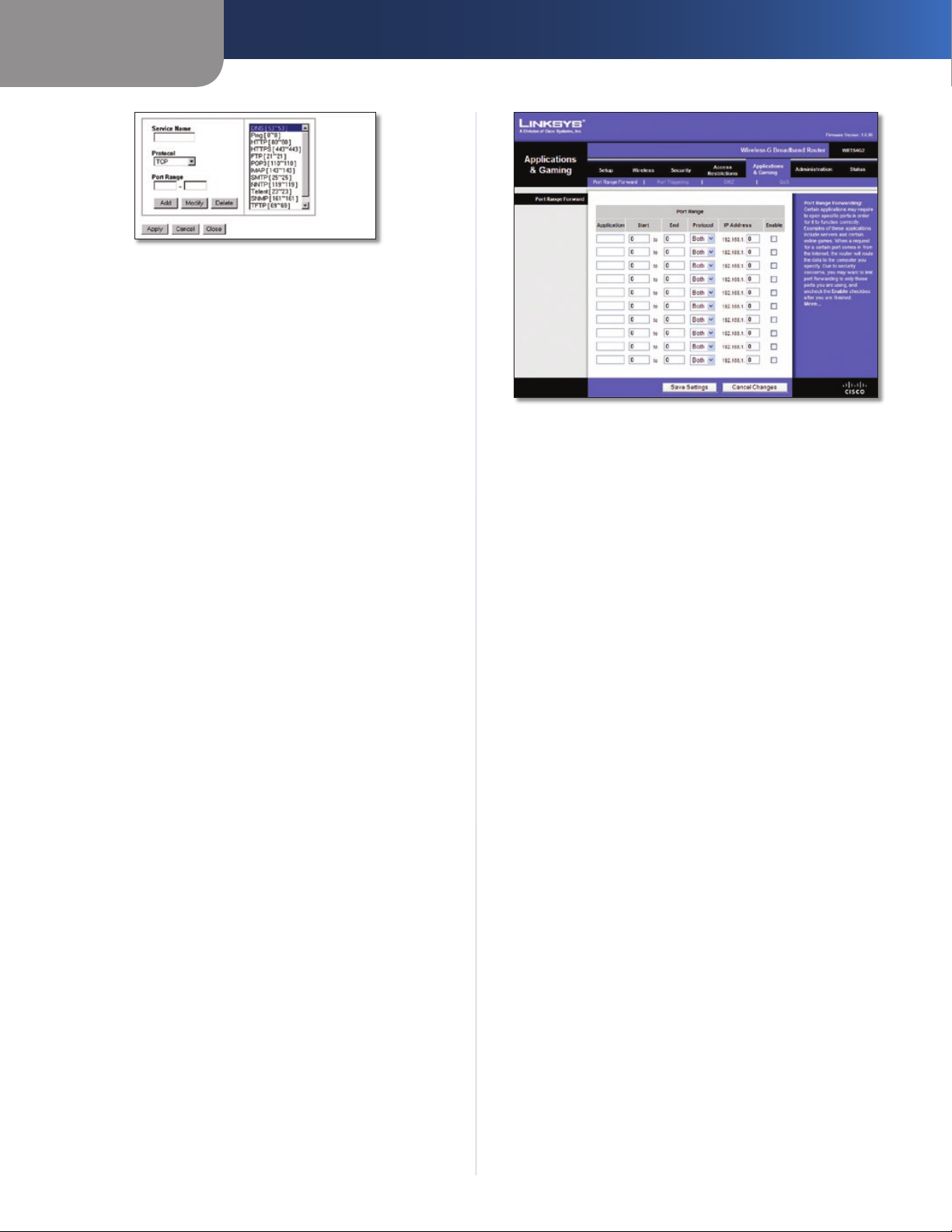
Capítulo 3
Servicios de puertos
Para agregar un servicio, introduzca el nombre del mismo
en el campo Service Name (Nombre de servicio). Seleccione
su protocolo en el menú desplegable Protocol (Protocolo) e
introduzca su intervalo en los campos Port Range (Intervalo
de puertos). A continuación, haga clic en Add (Agregar).
Para modificar un servicio, selecciónelo en la lista de la
parte derecha. Cambie su nombre, parámetro de protocolo
o intervalo de puertos. A continuación, haga clic en Modify
(Modificar).
Para eliminar un servicio, selecciónelo en la lista de la parte
derecha. A continuación, haga clic en Delete (Eliminar).
Cuando termine de efectuar cambios en la pantalla de
servicios de puertos, haga clic en Apply (Aplicar) para guardar
los cambios. Si desea borrar los cambios, haga clic en Cancel
(Cancelar). Para cerrar la pantalla Port Services (Servicios de
puertos) y volver a la pantalla Access Restrictions (Restricciones
de acceso), haga clic en Close (Cerrar).
Website Blocking by URL Address (Bloqueo de sitios web por
dirección URL)
Si desea bloquear sitios web con direcciones URL específicas,
introduzca cada una en un campo independiente situado
junto a Website Blocking by URL Address (Bloqueo de sitios
web por dirección URL).
Website Blocking by Keyword (Bloqueo de sitios web por
palabra clave)
Si desea bloquear sitios web mediante palabras clave
específicas, introduzca cada una en un campo independiente
situado junto a Website Blocking by Keyword (Bloqueo de sitios
web por palabra clave).
Haga clic en Save Settings (Guardar parámetros) para guardar
los cambios o en Cancel Changes (Cancelar cambios) para
eliminarlos.
Configuración avanzada
Applications and Gaming > Port Range Forward (Aplicaciones y juegos
> Reenvío de intervalos de puertos)
Port Range Forward (Reenvío de intervalos de
puertos)
Para reenviar un puerto, introduzca la información solicitada
en cada línea, según los criterios pertinentes.
Application (Aplicación) Introduzca en este campo el
nombre que desea asignar a la aplicación. Cada nombre
puede tener hasta 12 caracteres.
Start/End (Inicio/Final) Se trata del intervalo de puertos.
Introduzca el número que inicia el intervalo de puertos en
la columna Inicio y el número que finaliza el intervalo en la
columna Final.
Protocol (Protocolo) Introduzca el protocolo que se utilizará
para esta aplicación, TCP, UDP o Both (Ambos).
IP Address (Dirección IP) Introduzca para cada aplicación
la dirección IP de la computadora que ejecuta la aplicación
específica.
Enable (Activar) Seleccione Enable (Activar) para activar el
reenvío de puertos para la aplicación correspondiente.
Haga clic en Save Settings (Guardar parámetros) para guardar
los cambios o en Cancel Changes (Cancelar cambios) para
eliminarlos.
Applications and Gaming > Port Range Forward (Aplicaciones y juegos > Reenvío de intervalos de puertos)
La pantalla Applications & Gaming > Port Range Forward
(Aplicaciones y juegos > Reenvío de intervalos de puertos)
permite configurar servicios públicos en la red, como servidores
web, servidores FTP, servidores de correo electrónico u otras
aplicaciones de Internet especializadas. (Las aplicaciones de
Internet especializadas son aquéllas que utilizan el acceso a
Internet para realizar funciones como videoconferencias o
juegos en línea. Puede que algunas aplicaciones de Internet no
requieran ningún reenvío).
Router de banda ancha Wireless-G
Applications & Gaming > Port Triggering (Aplicaciones y juegos > Desencadenado de puertos)
La pantalla Applications & Gaming > Port Triggering
(Aplicaciones y juegos > Desencadenado de puertos)
permite que el router controle los datos salientes de números
de puerto específicos. El router recuerda la dirección IP de la
computadora que envía los datos coincidentes, de forma
que, cuando los datos solicitados circulen a través del router,
se dirijan a la computadora correspondiente mediante la
dirección IP y las reglas de asignación de puertos.
17
Page 76

Capítulo 3
Applications and Gaming > Port Triggering (Aplicaciones y juegos >
Desencadenado de puertos)
Port Triggering (Desencadenado de puertos)
Application (Aplicación) Introduzca el nombre de aplicación
del desencadenador.
Triggered Range (Intervalo desencadenado)
Introduzca para cada aplicación el intervalo de números de
puertos desencadenados. Consulte en la documentación de
la aplicación de Internet los números de puerto necesarios.
Start Port (Puerto inicial) Introduzca el número de puerto
inicial del intervalo desencadenado.
End Port (Puerto final) Introduzca el número de puerto final
del intervalo desencadenado.
Forwarded Range (Intervalo reenviado)
Introduzca para cada aplicación el intervalo de números de
puertos reenviados. Consulte en la documentación de la
aplicación de Internet los números de puerto necesarios.
Start Port (Puerto inicial) Introduzca el número de puerto
inicial del intervalo reenviado.
End Port (Puerto final) Introduzca el número de puerto final
del intervalo reenviado.
Enable (Activar) Seleccione Enable (Activar) para
activar el desencadenado de puertos para la aplicación
correspondiente.
Haga clic en Save Settings (Guardar parámetros) para guardar
los cambios o en Cancel Changes (Cancelar cambios) para
eliminarlos.
Configuración avanzada
Applications and Gaming (Aplicaciones y juegos) > DMZ
DMZ
Cualquier PC cuyo puerto se reenvíe debe tener la función de
cliente DHCP desactivada y debe tener asignada una nueva
dirección IP estática, ya que su dirección IP puede cambiar al
utilizar la función DHCP.
Para exponer una computadora, seleccione Enable
(Activar). A continuación, introduzca la dirección IP de la
computadora en el campo DMZ Host IP Address (Dirección
IP de asignación de DMZ). Esta función está desactivada de
forma predeterminada.
Haga clic en Save Settings (Guardar parámetros) para guardar
los cambios o en Cancel Changes (Cancelar cambios) para
eliminarlos.
Applications and Gaming (Aplicaciones y juegos) > QoS
La calidad de servicio (QoS) garantiza un servicio óptimo para
tipos de tráfico de red de alta prioridad, que pueden consistir
en aplicaciones en tiempo real y muy exigentes, como las
videoconferencias.
Existen tres tipos de QoS disponibles: Device Priority (Prioridad
de dispositivos), Ethernet Port Priority (Prioridad de puertos
Ethernet) y Application Priority (Prioridad de aplicaciones).
QoS
Enable/Disable (Activar/Desactivar) Para activar QoS,
seleccione Enable (Activar). En caso contrario, seleccione
Disable (Desactivar). QoS está desactivado de forma
predeterminada.
Upstream Bandwidth (Ancho de banda de flujo
ascendente) Seleccione Auto (Automático) o Manual en el
menú desplegable. La opción manual le permite especificar
el máximo ancho de banda saliente que la aplicación puede
utilizar.
Applications and Gaming (Aplicaciones y
juegos) > DMZ
La función DMZ permite exponer una computadora de red a
Internet para el uso de un servicio especial, como juegos por
Internet y videoconferencias. La asignación de DMZ reenvía
todos los puertos a una computadora al mismo tiempo. La
función de reenvío de intervalos de puertos es más segura
porque sólo abre los puertos que usted desee, mientras
que la asignación de DMZ abre todos los puertos de una
computadora, exponiéndolo a Internet.
Router de banda ancha Wireless-G
18
Page 77
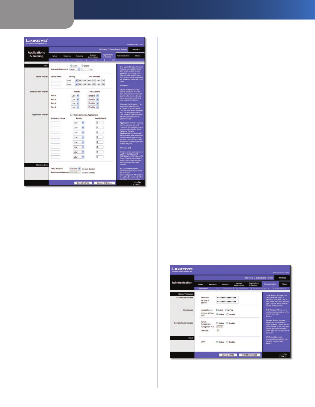
Capítulo 3
Applications and Gaming (Aplicaciones y juegos) > QoS
Device Priority (Prioridad de dispositivos)
Introduzca el nombre del dispositivo de red en el campo
Device name (Nombre de dispositivo), introduzca su dirección
MAC y, a continuación, seleccione su prioridad en el menú
desplegable.
Configuración avanzada
Half-Life, Age of Empires, EverQuest, Quake2/Quake3 y Diablo
II. El valor predeterminado no está seleccionado.
Application Name (Nombre de aplicación) Introduzca
el nombre que desea asignar a la aplicación en el campo
Application Name (Nombre de aplicación).
Priority (Prioridad) Seleccione una prioridad High (Alta) o
Low (Baja) para la aplicación. La selección predeterminada
es Low (Baja).
Specific Port # (Número de puerto específico) Introduzca el
número de puerto para la aplicación.
Wireless QoS (QoS inalámbrica)
WMM Support (Compatibilidad con WMM) Wi-Fi Multimedia
(WMM), antes conocido como Extensiones multimedia
inalámbricas (WME), es una función certificada de Wi-Fi
Alliance basada en el estándar IEEE 802.11. Esta opción
proporciona calidad de servicio a las redes inalámbricas.
Esta opción está especialmente indicada para aplicaciones
de vídeo, música y voz; por ejemplo, voz sobre IP (VoIP),
transmisión de vídeos y juegos interactivos. Si dispone de
otros dispositivos en la red inalámbrica que sean compatibles
con WMM, seleccione Enabled (Activado). De lo contrario,
mantenga el valor predeterminado Disabled (Desactivado).
No Acknowledgement (Sin confirmación) Esta función evita
que el router vuelva a enviar los datos si se produce un error.
Para utilizar esta función, seleccione Enabled (Activado). De
lo contrario, mantenga el valor predeterminado Disabled
(Desactivado).
Haga clic en Save Settings (Guardar parámetros) para guardar
los cambios o en Cancel Changes (Cancelar cambios) para
eliminarlos.
Administration > Management
Ethernet Port Priority (Prioridad de puertos Ethernet)
El tipo de QoS Ethernet Port Priority (Prioridad de puertos
Ethernet) permite asignar prioridades de rendimiento a los
puertos del router, los puertos LAN de 1 a 4. Para cada puerto,
seleccione la prioridad y el parámetro de control de flujo.
Priority (Prioridad) Seleccione High (Alta) o Low (Baja) en la
columna Priority (Prioridad). Se ha asignado prioridad baja a
los cuatro puertos del router de forma predeterminada.
Flow Control (Control de flujo) Si desea que el router
controle la transmisión de datos entre los dispositivos de red,
seleccione Enabled (Activado). Para desactivar esta función,
seleccione Disabled (Desactivado). El tipo de QoS Ethernet
Port Priority (Prioridad de puertos Ethernet) no requiere
compatibilidad por parte del ISP, ya que los puertos con
prioridad (puertos LAN de 1 a 4) se encuentran en la red. Esta
función está activada de forma predeterminada.
Application Priority (Prioridad de aplicaciones)
El tipo de QoS Application Priority (Prioridad de aplicaciones)
administra la información cuando se transmite y se recibe.
Según los parámetros de la pantalla QoS, esta función
asignará a la información una prioridad alta o baja para las
aplicaciones que especifique.
Optimize Gaming Applications (Optimizar juegos)
Seleccione esta función para permitir automáticamente que
los puertos de las aplicaciones de juegos tengan una prioridad
superior. Estos juegos incluyen, entre otros: Counter-Strike,
(Administración > Gestión)
La pantalla Administration > Management (Administración >
Gestión) permite que el administrador de la red administre
funciones específicas del router para el acceso y la
seguridad.
Administration > Management (Administración > Gestión)
Router de banda ancha Wireless-G
19
Page 78
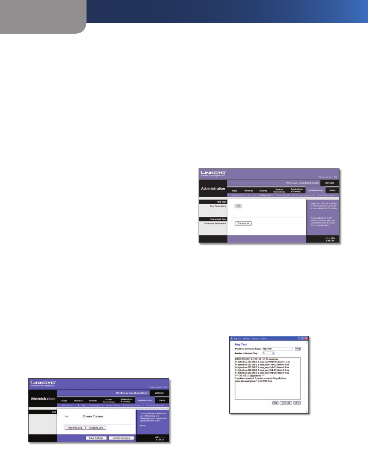
Capítulo 3
Configuración avanzada
Router Password (Contraseña del router)
Local Router Access (Acceso al router local)
Router Password (Contraseña del router) ntroduzca una
nueva contraseña para el router.
Re-enter to confirm (Confirmar contraseña) Vuelva a
introducir la contraseña para confirmarla.
Web Access (Acceso web)
Access Server (Servidor de acceso) HTTP (protocolo de
transferencia de hipertexto) es el protocolo de comunicaciones
utilizado para conectarse a los servidores de la web. HTTPS
utiliza SSL (capa de socket seguro) para encriptar los datos
transmitidos para una mayor seguridad. Seleccione HTTP o
HTTPS. La opción predeterminada es HTTP.
Wireless Access Web (Web de acceso inalámbrico) Si utiliza
el router en un dominio público donde se concede acceso
inalámbrico a los invitados, puede desactivar el acceso
inalámbrico a la utilidad basada en web del router. Si desactiva
el parámetro sólo podrá acceder a la utilidad web mediante
una conexión con cable. Mantenga el valor predeterminado
Enable (Activar) para permitir el acceso inalámbrico a la utilidad
basada en web del router o seleccione Disable (Desactivar)
para desactivar el acceso inalámbrico a la utilidad.
Remote Router Access (Acceso remoto al router)
Remote Management (Administración remota) Para
acceder al router de forma remota desde fuera de la red local,
seleccione Enable (Activar).
Management Port (Puerto de administración) Introduzca
el número de puerto que se abrirá al acceso exterior. Como
es habitual, tendrá que introducir la contraseña del router
cuando acceda al mismo de este modo.
Use https (Utilizar https) Seleccione esta función para
solicitar el uso de HTTPS para acceso remoto.
UPnP
UPnP Mantenga el valor predeterminado Enable (Activar)
para activar la función UPnP; de lo contrario, seleccione
Disable (Desactivar).
Haga clic en Save Settings (Guardar parámetros) para guardar
los cambios o en Cancel Changes (Cancelar cambios) para
eliminarlos.
Log (Registro)
Log (Registro) Para desactivar la función de registro,
mantenga el parámetro predeterminado Disable (Desactivar).
Para controlar el tráfico entre la red e Internet, seleccione
Enable (Activar).
Cuando desee ver los registros, haga clic en Incoming Log
(Registro de entrada) o Outgoing Log (Registro de salida),
según el que desee ver.
Haga clic en Save Settings (Guardar parámetros) para guardar
los cambios o en Cancel Changes (Cancelar cambios) para
eliminarlos.
Administration > Diagnostics (Administración > Diagnóstico)
Las pruebas de diagnóstico (ping y traceroute) permiten
comprobar las conexiones de los componentes de red.
Administration > Diagnostics (Administración > Diagnóstico)
Ping Test (Prueba de ping)
Ping La prueba de ping comprueba el estado de una
conexión. Haga clic en Ping para abrir la pantalla Ping Test
(Prueba de ping). Introduzca la dirección de la computadora
cuya conexión desea probar y el número de veces que desea
probarla. A continuación, haga clic en Ping. La pantalla Ping
Test (Prueba de Ping) mostrará si la prueba se ha realizado
con éxito. Para detener la prueba, haga clic en Stop (Detener).
Haga clic en Clear Log (Borrar registro) para borrar la pantalla.
Haga clic en el botón Close (Cerrar) para volver a la pantalla
Diagnostics (Diagnóstico).
Administration > Log (Administración > Registro)
El router puede mantener registros de todo el tráfico de la
conexión a Internet.
Administration > Log (Administración > Registro)
Router de banda ancha Wireless-G
Ping Test (Prueba de ping)
20
Page 79
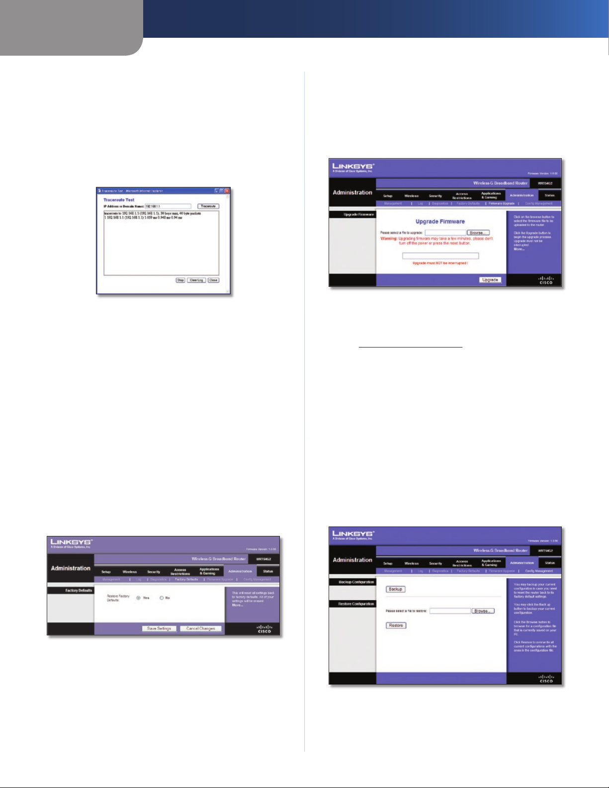
Capítulo 3
Configuración avanzada
Traceroute Test (Prueba de traceroute)
Traceroute Para probar el rendimiento de una conexión,
haga clic en Traceroute para abrir la pantalla Prueba de
traceroute. Introduzca la dirección de la computadora cuya
conexión desea probar y haga clic en Traceroute. La pantalla
Traceroute Test (Prueba de traceroute) mostrará si la prueba
se ha realizado con éxito. Para detener la prueba, haga clic en
Stop (Detener). Haga clic en Clear Log (Borrar registro) para
borrar la pantalla. Haga clic en el botón Close (Cerrar) para
volver a la pantalla Diagnostics (Diagnóstico).
Traceroute Test (Prueba de traceroute)
Administration > Factory Defaults (Administración > Parámetros predeterminados de fábrica)
La pantalla Administration > Factory Defaults
(Administración > Parámetros predeterminados de fábrica)
permite restaurar la configuración del router con los
parámetros predeterminados de fábrica.
Administration > Upgrade Firmware (Administración > Actualizar el firmware)
La pantalla Administration > Upgrade Firmware (Administración
> Actualizar el firmware) permite actualizar el firmware del
router. No actualice el firmware a menos que tenga problemas
con el router o desee utilizar una función del nuevo router.
Administration > Upgrade Firmware (Administración > Actualizar el
Antes de actualizar el firmware, descargue el archivo de
actualización del firmware del router desde el sitio web de
Linksys, www.linksysbycisco.com.
Upgrade Firmware (Actualizar el firmware)
Please select a file to upgrade (Seleccione un archivo que
actualizar) Haga clic en Browse (Examinar) y seleccione el
archivo de actualización de firmware. A continuación, haga
clic
en
Upgrade (Actualizar) y siga las instrucciones que
aparecen en la pantalla.
firmware)
Factory Defaults (Parámetros predeterminados
de fábrica)
Restore Factory Defaults (Restaurar parámetros
predeterminados de fábrica) Para restablecer los parámetros
del router en sus valores predeterminados, seleccione Ye s
(Sí) y, a continuación, haga clic en Save Settings (Guardar
parámetros). Los parámetros que haya guardado se perderán
al restaurar los parámetros predeterminados.
Administration > Factory Defaults (Administración > Parámetros
predeterminados de fábrica)
Administration > Config Management (Administración > Administración de la configuración)
Esta pantalla se utiliza para realizar una copia de seguridad
del archivo de configuración del router o para restaurarlo.
Administration > Config Management (Administración >
Administración de la configuración)
Router de banda ancha Wireless-G
21
Page 80
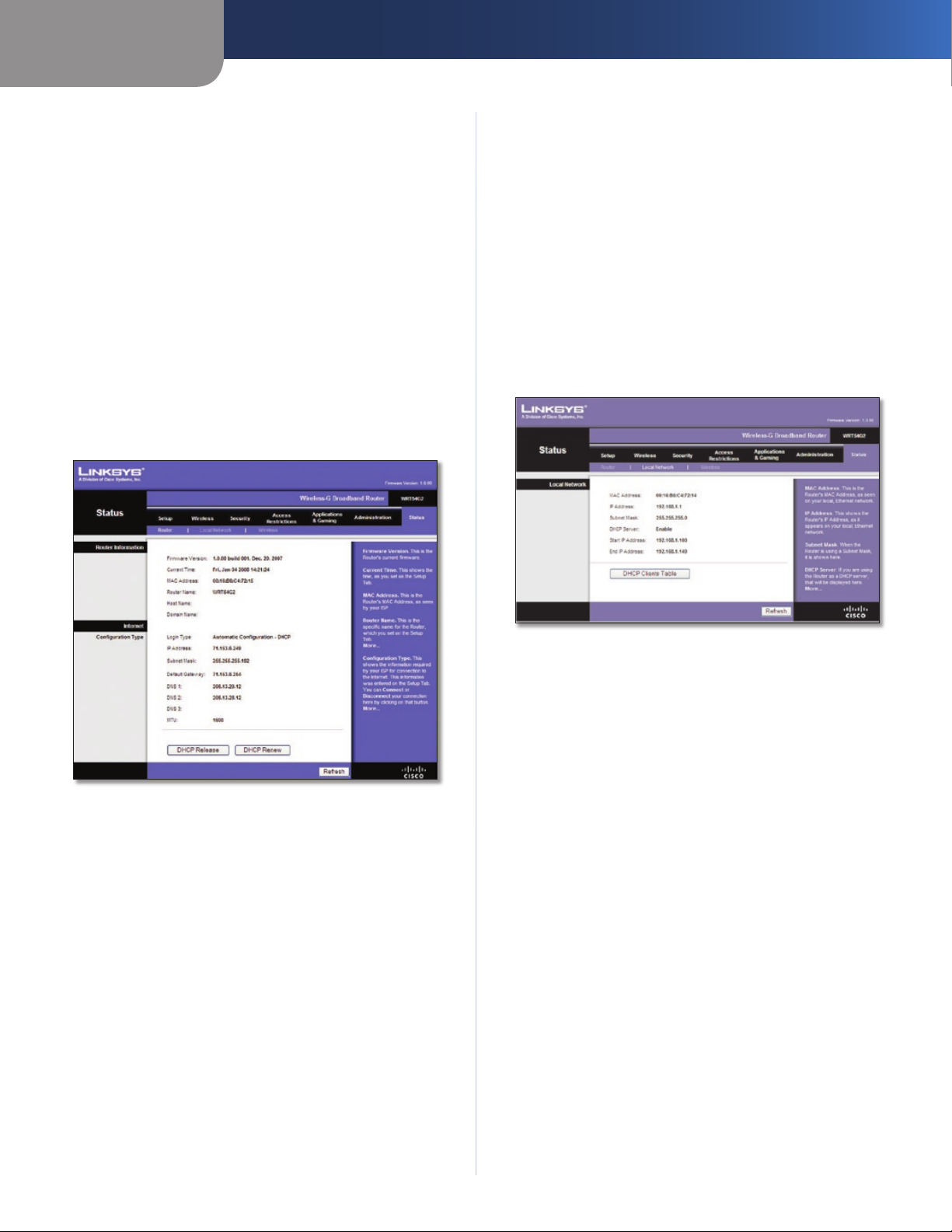
Capítulo 3
Configuración avanzada
Backup Configuration (Configuración de copia de
seguridad)
Para realizar una copia de seguridad del archivo de
configuración del router, haga clic en Backup (Copia de
seguridad). A continuación, siga las instrucciones que
aparecen en pantalla.
Restore Configuration (Restauración de la
configuración)
Please select a file to restore (Seleccione un archivo que
restaurar) Haga clic en Browse (Examinar) y seleccione
el archivo de configuración. A continuación, haga clic en
Restore (Restauración).
Status (Estado) > Router
La pantalla Status (Estado) > Router muestra el estado actual
del router.
Internet
Configuration Type (Tipo de configuración)
Esta sección muestra la información de red actual almacenada
en el router. La información varía en función del tipo de
conexión a Internet seleccionada en la pantalla Setup > Basic
Setup (Configuración > Configuración básica).
Haga clic en el botón Refresh (Actualizar) para actualizar la
información de la pantalla.
Status > Local Network (Estado > Red local)
La pantalla Status > Local Network (Estado > Red local)
muestra el estado de la red.
Status (Estado) > Router
Router Information (Información del router)
Firmware Version (Versión del firmware) Se muestra el
número de versión del firmware actual del router.
Current Time (Hora actual) Se muestra la hora establecida
en el router.
MAC Address (Dirección MAC) Se muestra la dirección MAC
del router tal como la ve el ISP.
Router Name (Nombre de router) Se muestra el nombre de
router, siempre que se haya introducido en la pantalla Setup
> Basic Setup (Configuración > Configuración básica).
Host Name (Nombre de host) Se muestra el nombre de host
del router, siempre que se haya introducido en la pantalla
Setup > Basic Setup (Configuración > Configuración básica).
Domain Name (Nombre de dominio) Se muestra el nombre
de dominio del router, siempre que se haya introducido en la
pantalla Setup > Basic Setup (Configuración > Configuración
básica).
Status > Local Network (Estado > Red local)
Local Network (Red local)
MAC Address (Dirección MAC) Indica la dirección MAC de la
interfaz con cables local del router.
IP Address (Dirección IP) Se muestra la dirección IP del
router, tal como aparece en la red local.
Subnet Mask (Máscara de subred) Se muestra la máscara de
subred del router.
DHCP Server (Servidor DHCP) Aquí se muestra el estado del
funcionamiento del servidor DHCP del router.
Start IP Address (Dirección IP inicial) Aquí se muestra la
dirección IP inicial del intervalo de direcciones IP que pueden
utilizar los dispositivos de la red local.
End IP Address (Dirección IP final) Aquí se muestra la
dirección IP final del intervalo de direcciones IP que pueden
utilizar los dispositivos de la red local.
DHCP Clients Table (Tabla de clientes DHCP) Haga clic
en este botón para ver la lista de computadoras u otros
dispositivos que están utilizando el router como servidor
DHCP.
Router de banda ancha Wireless-G
22
Page 81

Capítulo 3
DHCP Clients Table (Tabla de clientes DHCP)
DHCP Clients Table (Tabla de clientes DHCP)
La tabla de clientes DHCP indica las computadora y otros
dispositivos a los que el router ha asignado direcciones
IP. La lista puede ordenarse por dirección IP, dirección
MAC, interfaz y nombre de cliente. Para quitar un cliente
DHCP, active la casilla de verificación Delete (Eliminar) y,
a continuación, haga clic en Delete (Eliminar). Haga clic
en Refresh (Actualizar) para actualizar la información de
la pantalla. Para salir de esta pantalla y volver a la pantalla
Local Network (Red local), haga clic en Close (Cerrar).
Configuración avanzada
Status > Wireless (Estado > Inalámbrica)
La pantalla Status > Wireless (Estado > Inalámbrica) muestra
el estado de la red inalámbrica.
Status > Wireless (Estado > Inalámbrica)
Wireless (Inalámbrico)
MAC Address (Dirección MAC) Indica la dirección MAC de la
interfaz inalámbrica local del router.
Mode (Modo) Indica el modo inalámbrico que utiliza la red.
(SSID) Se muestra el nombre de la red inalámbrica, también
denominado SSID.
DHCP Server (Servidor DHCP) Se muestra el estado del
funcionamiento del servidor DHCP.
Channel (Canal) Se muestra el canal en el que transmite la
red inalámbrica.
Encryption Function (Función de encriptación) Se muestra
el estado de la función de seguridad inalámbrica del router.
Haga clic en el botón Refresh (Actualizar) para actualizar la
información de la pantalla.
Router de banda ancha Wireless-G
23
Page 82

Apéndice A
Resolución de problemas
Apéndice A: Resolución de problemas
Su computadora no puede conectarse a Internet.
Siga las siguientes instrucciones hasta que la computadora
pueda conectarse a Internet:
•
Asegúrese de que el router está encendido. La luz
de alimentación debe estar encendida y no debe
parpadear.
•
Si la luz de alimentación parpadea, apague todos los
dispositivos de red, incluidos el módem, el router y
las computadoras. A continuación, encienda cada
dispositivo en el siguiente orden:
Módem por cable o DSL1.
Router2.
Computadora3.
•
Compruebe las conexiones de los cables. La computadora
debe estar conectada a uno de los puertos numerados
del 1 al 4 del router y el módem al puerto de Internet
del router.
El módem no dispone de puerto Ethernet.
El módem es un módem de acceso telefónico para el servicio
de acceso telefónico tradicional. Para utilizar este router,
necesita un módem por cable/DSL y una conexión a Internet
de alta velocidad.
No puede utilizar el servicio DSL para conectarse de
forma manual a Internet.
Una vez que haya instalado el router, se conectará
automáticamente al proveedor de servicios de Internet
(ISP), para que no tenga que volver a conectarse de forma
manual.
Al hacer doble clic en el explorador web, se le solicitará
un nombre de usuario y una contraseña. Si desea evitar
esta solicitud, siga las siguientes instrucciones.
Abra el explorador web y complete los siguientes pasos
(estos pasos son específicos para Internet Explorer, pero son
similares para otros exploradores):
Seleccione 1. Herramientas > Opciones de Internet.
Haga clic en la ficha 2. Conexiones.
Seleccione 3. No marcar nunca una conexión.
Haga clic en 4. Aceptar.
El router no tiene un puerto coaxial para la conexión por
cable.
El router no es un sustituto del módem. El módem por cable
sigue siendo necesario para utilizar el router. Conecte la
conexión por cable al módem por cable, inserte el CD de
configuración en la computadora y, a continuación, siga las
instrucciones-que aparecen en pantalla.
La computadora no puede conectarse a la red de forma
inalámbrica.
Asegúrese de que el nombre de la red inalámbrica o SSID
es el mismo en la computadora y el router. Si ha activado la
seguridad inalámbrica, asegúrese de que la computadora y
el router utilizan el mismo método de seguridad y la misma
clave.
Debe modicar los parámetros del router.
Abra el explorador web (por ejemplo, Internet Explorer o
Firefox) e introduzca la dirección IP del router en el campo
de dirección (la dirección IP predeterminada es 192.168.1.1).
Cuando se le solicite, deje en blanco el campo Nombre
de usuario e introduzca la contraseña para el router (la
contraseña predeterminada es admin). Haga clic en la ficha
correspondiente para cambiar los parámetros.
La línea telefónica DSL no encaja en el puerto Internet
del router.
El router no es un sustituto del módem. Sigue siendo
necesario el módem DSL para utilizar el router. Conecte la línea
telefónica al módem DSL, inserte el CD de configuración en
la computadora y, a continuación, siga las instrucciones-que
aparecen en pantalla.
Router de banda ancha Wireless-G
WEB: Si no ha encontrado respuesta a sus
dudas, consulte el sitio web de Linksys,
www.linksysbycisco.com.
24
Page 83

Apéndice B
Apéndice B: Especificaciones
Modelo WRT54G2
Estándares IEEE 802.3, IEEE 802.3u, IEEE
802.11g, IEEE 802.11b
Puertos Internet, Ethernet (1-4),
Alimentación
Botones Reinicio, Wi-Fi Protected Setup™
Luces Alimentación, Internet, Ethernet
(1-4), Conexión inalámbrica,
Wi-Fi Protected Setup™
Tipo de cableado CAT 5
Número de antenas 1 antena interna
Desmontable No
Potencia de salida de
radiofrecuencia 18 dBm
Cert./compat. UPnP Compatible
Funciones de seguridad Firewall con inspección
exhaustiva de paquetes (SPI),
directiva de Internet
Seguridad inalámbrica Wi-Fi Protected Access™ 2
(acceso Wi-Fi protegido, WPA2),
WEP, ltrado de direcciones MAC
inalámbrico
Especificaciones
Condiciones ambientales
Dimensiones 203 mm x 35 mm x 160 mm
(7,99” x 1,38” x 6,30”)
Peso 280 g (9,88 onzas)
Alimentación Externa, 12 V CC, 0,5 A
Certicaciones FCC, UL, ICES-003, RSS210, CE,
Wi-Fi CERTIFIED™ (802.11b,
802.11g), WPA2™, WMM®, Wi-Fi
Protected Setup™
Temperatura de
funcionamiento 0 a 40 °C (32 a 104 °F)
Temperatura de
almacenamiento -20 a 60 °C (-4 a 140 °F)
Humedad de
funcionamiento Entre 10 y 85%, sin condensación
Humedad de
almacenamiento Entre 5 y 90%, sin condensación
Router de banda ancha Wireless-G
25
Page 84

Apéndice C
Información de garantía
Apéndice C: Información de garantía
Garantía limitada
Linksys garantiza que este producto de hardware de Linksys
estará exento de defectos de fabricación en los materiales
y en condiciones normales de uso durante el periodo de
garantía, que comienza en la fecha de adquisición por parte
del comprador y usuario final inicial y se extiende durante el
periodo que se especifica a continuación:
•
Un (1) año para productos nuevos
Noventa (90) días para productos reparados •
El único recurso y la responsabilidad de Linksys en virtud de
la presente garantía limitada será que Linksys, a su elección,
(a) repare el producto con piezas nuevas o reparadas, (b)
sustituya el producto por otro producto nuevo o reparado
de Linksys equivalente que se encuentre disponible de
forma razonable, o (c) reembolse el precio de la compra del
producto, excepto los posibles descuentos. Todo producto
reparado o sustituido estará garantizado durante el tiempo
restante del periodo de garantía original o durante treinta
(30) días, siendo válida la opción de mayor duración. Todos los
productos y piezas que se sustituyan pasarán a ser propiedad
de Linksys.
Linksys garantiza de forma adicional que cualquier medio en
el que se proporcione el software estará exento de defectos
de materiales y fabricación en condiciones normales de
uso durante un periodo de noventa (90) días a partir de la
fecha original de compra. En virtud de esta garantía limitada,
el único recurso del usuario y toda la responsabilidad de
Linksys consistirá en que Linksys, a su discreción, (a) sustituya
el medio del software, o (b) reembolse el precio de compra
del software.
Exclusiones y limitaciones
Esta garantía limitada dejará de tener vigor si: (a) se ha
eliminado o dañado el sello de montaje del producto, (b)
el producto se ha modificado o alterado, salvo si Linksys ha
efectuado tal modificación o reparación; (c) el producto se ha
dañado debido a un uso con productos de otros fabricantes,
(d) el producto no se ha instalado, utilizado, reparado o
mantenido de acuerdo con las instrucciones suministradas
por Linksys, (e) se ha sometido al producto a una fuerza física
o eléctrica no habituales, un uso incorrecto, negligencias o
accidentes, (f) el número de serie del producto se ha alterado,
eliminado o borrado, o (g) el producto se suministra o se
otorga con licencia para una versión beta, para su evaluación
o para realización de demostraciones, por tanto, Linksys no
cobra una tasa de compra ni de licencia.
SALVO POR LA GARANTÍA LIMITADA A LOS MEDIOS
ESTABLECIDA ANTERIORMENTE Y EN EL ÁMBITO DE LEY
APLICABLE, TODO EL SOFTWARE QUE LINKSYS PROPORCIONA
JUNTO CON EL PRODUCTO, YA SEA CARGADO EN FÁBRICA, EN
EL PRODUCTO O EN UNO DE LOS MEDIOS QUE ACOMPAÑAN
AL PRODUCTO, SE FACILITA "TAL CUAL", SIN GARANTÍA
DE NINGÚN TIPO. Sin perjuicio de lo anterior, Linksys no
garantiza que el funcionamiento del producto o del software
se realice de forma continuada o que no tenga errores. Del
mismo modo y debido al continuo desarrollo de nuevas
técnicas de intrusión y ataques a la red, Linksys no garantiza
que el producto, el software o cualquier tipo de dispositivo,
sistema o red en los que se utilice el producto o el software
estén exentos de vulnerabilidades a intrusiones o ataques.
Es posible que este producto incluya o contenga software u
ofertas de servicio de terceros. Esta garantía limitada no se
aplicará a dicho software u ofertas de servicio de terceros.
La presente garantía limitada no asegura la disponibilidad
continuada de un servicio de terceros que pudiera ser
necesario para la utilización o el funcionamiento de este
producto.
EN LA MEDIDA EN QUE LA LEGISLACIÓN APLICABLE LO
PERMITA, TODAS LAS GARANTÍAS IMPLÍCITAS Y CONDICIONES
DE COMERCIALIZACIÓN, CALIDAD SATISFACTORIA O
IDONEIDAD PARA UN FIN EN PARTICULAR ESTÁN LIMITADAS
A LA DURACIÓN DEL PERIODO DE GARANTÍA. SE NIEGAN
EL RESTO DE CONDICIONES, ASUNCIONES Y GARANTÍAS
IMPLÍCITAS O EXPLÍCITAS. En algunas jurisdicciones no está
permitido limitar la duración de una garantía implícita, por
lo que es posible que la limitación mencionada no se aplique
en su caso. Esta garantía limitada confiere al usuario derechos
legales específicos. Además, es posible que goce de otros
derechos que varían según la jurisdicción.
EN LA MEDIDA EN QUE LA LEGISLACIÓN APLICABLE LO
PERMITA, LINKSYS NO SERÁ RESPONSABLE EN NINGÚN CASO
POR LAS PÉRDIDAS DE DATOS, INGRESOS O BENEFICIOS, NI
POR DAÑOS O PERJUICIOS CUANTIFICABLES, INDIRECTOS
O PUNITIVOS, CON INDEPENDENCIA DE LA TEORÍA DE LA
RESPONSABILIDAD (INCLUIDA LA NEGLIGENCIA), DERIVADOS
DEL USO DEL PRODUCTO, EL SOFTWARE O EL SERVICIO O
RELACIONADO CON ÉSTE, AUNQUE SE HAYA ADVERTIDO
A LINKSYS DE LA POSIBILIDAD DE TALES DAÑOS. EN LA
MEDIDA EN QUE LA LEGISLACIÓN APLICABLE LO PERMITA,
EN NINGÚN CASO LA RESPONSABILIDAD DE LINKSYS SERÁ
SUPERIOR AL IMPORTE QUE EL USUARIO HAYA ABONADO
POR EL PRODUCTO. Se aplicarán las limitaciones precedentes
incluso en el caso de que algún recurso o garantía estipulados
en esta garantía limitada no cumpla con su finalidad esencial.
En algunas jurisdicciones no está permitido excluir o limitar
los daños derivados o indirectos, por lo que puede que la
limitación o exclusión mencionada no se aplique en su caso.
Obtención del servicio de garantía
Si tiene alguna pregunta sobre el producto o si tiene problemas
al utilizarlo, visite www.linksysbycisco.com/support,
donde podrá encontrar diversas herramientas de asistencia
técnica en línea, así como información de ayuda relacionada
con el producto. Si el producto presenta defectos durante
el periodo de garantía, póngase en contacto con el servicio
de asistencia técnica de Linksys para obtener instrucciones
sobre cómo disfrutar del servicio de garantía. Podrá
encontrar el número de teléfono de asistencia técnica de
Linksys correspondiente a su zona en la guía del usuario y
en la dirección www.linksysbycisco.com. Cuando llame,
tenga preparado el número de serie de su producto y la
prueba de compra. PARA PROCESAR RECLAMACIONES DE
GARANTÍA, ES NECESARIO CONTAR CON UNA PRUEBA DE
COMPRA ORIGINAL FECHADA. Si se le solicita la devolución
del producto, se le asignará un número RMA (Autorización de
devolución de material). El envío y el embalaje correctos del
producto a Linksys corren por su cuenta y riesgo. Al devolver
el producto, debe incluir el número RMA y una copia de la
prueba de compra original fechada. No se aceptarán los
productos recibidos sin número RMA y sin una prueba de
compra original fechada. No incluya ningún otro elemento
junto con el producto que vaya a devolver a Linksys. Los
productos defectuosos que cubra esta garantía limitada se
Router de banda ancha Wireless-G
26
Page 85

Apéndice C
repararán o sustituirán y se devolverán sin ningún tipo de
cargo. Aquellos clientes ubicados fuera de los Estados Unidos
de América y Canadá serán responsables de todos los gastos
de embalaje y envío, gestión, aduanas, IVA y otros impuestos
y cargos asociados. Las reparaciones o sustituciones que
no cubra esta garantía limitada estarán sujetas a las tarifas
vigentes de Linksys.
Asistencia técnica
Esta garantía limitada no es un contrato de servicio ni
de asistencia. Podrá encontrar información acerca de las
ofertas y políticas de asistencia técnica actuales de Linksys
(incluidas las tarifas de los servicios de asistencia técnica) en
www.linksysbycisco.com/support.
Esta garantía limitada está sujeta a las leyes de la jurisdicción
donde adquirió el producto.
Dirija todas sus preguntas a: Linksys, P.O. Box 18558, Irvine,
CA 92623 (EE. UU.).
Información de garantía
Router de banda ancha Wireless-G
27
Page 86

Apéndice D
Información sobre normativa
Apéndice D: Información sobre normativa
FCC Statement
This device complies with Part 15 of the FCC Rules.
Operation is subject to the following two conditions: (1)
This device may not cause harmful interference, and (2) this
device must accept any interference received, including
interference that may cause undesired operation.
This product has been tested and complies with the
specifications for a Class B digital device, pursuant to Part
15 of the FCC Rules. These limits are designed to provide
reasonable protection against harmful interference in
a residential installation. This equipment generates,
uses, and can radiate radio frequency energy and, if not
installed and used according to the instructions, may
cause harmful interference to radio communications.
However, there is no guarantee that interference will not
occur in a particular installation. If this equipment does
cause harmful interference to radio or television reception,
which is found by turning the equipment off and on, the
user is encouraged to try to correct the interference by
one or more of the following measures:
•
Reorient or relocate the receiving antenna
Increase the separation between the equipment or •
devices
Safety Notices
WARNING: Do not use this product near water,
for example, in a wet basement or near a
swimming pool.
WARNING: Avoid using this product during an
electrical storm. There may be a remote risk of
electric shock from lightning.
WARNING: This product contains lead, known
to the State of California to cause cancer, and
birth defects or other reproductive harm. Wash
hands after handling.
Industry Canada Statement
This Class B digital apparatus complies with Canadian
ICES-003 and RSS210.
Operation is subject to the following two conditions:
This device may not cause interference and1.
This device must accept any interference, including 2.
interference that may cause undesired operation of
the device. This device has been designed to operate
with an antenna having a maximum gain of 1.8 dBi.
Antenna having a higher gain is strictly prohibited per
regulations of Industry Canada. The required antenna
impedance is 50 ohms.
Connect the equipment to an outlet other than the •
receiver’s
•
Consult a dealer or an experienced radio/TV technician
for assistance
FCC Caution: Any changes or modifications not expressly
approved by the party responsible for compliance could
void the user’s authority to operate this equipment.
FCC Radiation Exposure Statement
This equipment complies with FCC radiation exposure
limits set forth for an uncontrolled environment. This
equipment should be installed and operated with
minimum distance 20 cm between the radiator and your
body.
This transmitter must not be co-located or operating in
conjunction with any other antenna or transmitter. IEEE
802.11b or 802.11g operation of this product in the USA is
firmware-limited to channels 1 through 11.
Industry Canada Radiation Exposure Statement:
This equipment complies with IC radiation exposure limits
set forth for an uncontrolled environment. This equipment
should be installed and operated with minimum distance
20 cm between the radiator & your body.
This transmitter must not be co-located or operating in
conjunction with any other antenna or transmitter.
Router de banda ancha Wireless-G
28
Page 87

Apéndice D
Información sobre normativa
Avis d’Industrie Canada
Cet appareil numérique de la classe B est conforme aux
normes NMB-003 et RSS210 du Canada.
L’utilisation de ce dispositif est autorisée seulement aux
conditions suivantes :
il ne doit pas produire de brouillage et 1.
il doit accepter tout brouillage radioélectrique reçu, 2.
même si ce brouillage est susceptible de compromettre
le fonctionnement du dispositif. Le dispositif a été
conçu pour fonctionner avec une antenne ayant un
gain maximum de 1,8 dBi. Les règlements d’Industrie
Canada interdisent strictement l’utilisation d’antennes
dont le gain est supérieur à cette limite. L’impédance
requise de l’antenne est de 50 ohms.
Avis d’Industrie Canada concernant l’exposition
aux radiofréquences :
Ce matériel est conforme aux limites établies par IC
en matière d’exposition aux radiofréquences dans un
environnement non contrôlé. Ce matériel doit être installé
et utilisé à une distance d’au moins 20 cm entre l’antenne
et le corps de l’utilisateur.
L’émetteur ne doit pas être placé près d’une autre antenne
ou d’un autre émetteur, ou fonctionner avec une autre
antenne ou un autre émetteur.
Wireless Disclaimer
The maximum performance for wireless is derived from
IEEE Standard 802.11 specifications. Actual performance
can vary, including lower wireless network capacity,
data throughput rate, range and coverage. Performance
depends on many factors, conditions and variables,
including distance from the access point, volume of
network traffic, building materials and construction,
operating system used, mix of wireless products used,
interference and other adverse conditions.
Avis de non-responsabilité concernant les appareils sans fil
Les performances maximales pour les réseaux sans fil
sont tirées des spécifications de la norme IEEE 802.11.
Les performances réelles peuvent varier, notamment
en fonction de la capacité du réseau sans fil, du débit
de la transmission de données, de la portée et de la
couverture. Les performances dépendent de facteurs,
conditions et variables multiples, en particulier de la
distance par rapport au point d’accès, du volume du trafic
réseau, des matériaux utilisés dans le bâtiment et du
type de construction, du système d’exploitation et de la
combinaison de produits sans fil utilisés, des interférences
et de toute autre condition défavorable.
Router de banda ancha Wireless-G
29
Page 88

Apéndice D
Información sobre normativa
Información para el usuario sobre productos de consumo incluidos en la directiva de la UE 2002/96/CE sobre residuos de aparatos eléctricos y electrónicos (WEEE)
Este documento contiene información importante para
los usuarios en relación con la eliminación y el reciclaje
adecuados de los productos de Linksys. Los consumidores
están obligados a cumplir este aviso con todos los
productos electrónicos en los que figure el símbolo
siguiente:
English - Environmental Information for Customers in
the European Union
European Directive 2002/96/EC requires that the equipment
bearing this symbol on the product and/or its packaging must
not be disposed of with unsorted municipal waste. The symbol
indicates that this product should be disposed of separately
from regular household waste streams. It is your responsibility to
dispose of this and other electric and electronic equipment via
designated collection facilities appointed by the government or
local authorities. Correct disposal and recycling will help prevent
potential negative consequences to the environment and
human health. For more detailed information about the disposal
of your old equipment, please contact your local authorities,
waste disposal service, or the shop where you purchased the
product.
Български (Bulgarian) - Информация относно
опазването на околната среда за потребители в
Европейския съюз
Европейска директива 2002/96/EC изисква уредите, носещи
този символ върху изделието и/или опаковката му, да не
се изхвърля т с несортирани битови отпадъци. Символът
обозначава, че изделието трябва да се изхвърля отделно от
сметосъбирането на обикновените битови отпадъци. Ваша
е отговорността този и другите електрически и електронни
уреди да се изхвърлят в предварително определени от
държавните или общински органи специализирани пунктове
за събиране. Правилното изхвърляне и рециклиране
ще спомогнат да се предотвратят евентуални вредни за
околната среда и здравето на населението последствия. За
по-подробна информация относно изхвърлянето на вашите
стари уреди се обърнете към местните власти, службите за
сметосъбиране или магазина, от който сте закупили уреда.
Čeština (Czech) - Informace o ochraně životního
prostředí pro zákazníky v zemích Evropské unie
Evropská směrnice 2002/96/ES zakazuje, aby zařízení označené
tímto symbolem na produktu anebo na obalu bylo likvidováno
s netříděným komunálním odpadem. Tento symbol udává,
že daný produkt musí být likvidován odděleně od běžného
komunálního odpadu. Odpovídáte za likvidaci tohoto produktu
a dalších elektrických a elektronických zařízení prostřednictvím
určených sběrných míst stanovených vládou nebo místními
úřady. Správná likvidace a recyklace pomáhá předcházet
potenciálním negativním dopadům na životní prostředí a lidské
zdraví. Podrobnější informace o likvidaci starého vybavení si
laskavě vyžádejte od místních úřadů, podniku zabývajícího se
likvidací komunálních odpadů nebo obchodu, kde jste produkt
zakoupili.
Dansk (Danish) - Miljøinformation for kunder i EU
EU-direktiv 2002/96/EF kræver, at udstyr der bærer dette symbol
på produktet og/eller emballagen ikke må bortskaffes som
usorteret kommunalt affald. Symbolet betyder, at dette produkt
skal bortskaffes adskilt fra det almindelige husholdningsaffald.
Det er dit ansvar at bortskaffe dette og andet elektrisk og
elektronisk udstyr via bestemte indsamlingssteder udpeget
af staten eller de lokale myndigheder. Korrekt bortskaffelse
og genvinding vil hjælpe med til at undgå mulige skader for
miljøet og menneskers sundhed. Kontakt venligst de lokale
myndigheder, renovationstjenesten eller den butik, hvor du
har købt produktet, angående mere detaljeret information om
bortskaffelse af dit gamle udstyr.
Deutsch (German) - Umweltinformation für Kunden
innerhalb der Europäischen Union
Die Europäische Richtlinie 2002/96/EC verlangt, dass technische
Ausrüstung, die direkt am Gerät und/oder an der Verpackung mit
diesem Symbol versehen ist , nicht zusammen mit unsortiertem
Gemeindeabfall entsorgt werden darf. Das Symbol weist darauf
hin, dass das Produkt von regulärem Haushaltmüll getrennt
entsorgt werden sollte. Es liegt in Ihrer Verantwortung, dieses
Gerät und andere elektrische und elektronische Geräte über
die dafür zuständigen und von der Regierung oder örtlichen
Behörden dazu bestimmten Sammelstellen zu entsorgen.
Ordnungsgemäßes Entsorgen und Recyceln trägt dazu bei,
potentielle negative Folgen für Umwelt und die menschliche
Gesundheit zu vermeiden. Wenn Sie weitere Informationen zur
Entsorgung Ihrer Altgeräte benötigen, wenden Sie sich bitte an
die örtlichen Behörden oder städtischen Entsorgungsdienste
oder an den Händler, bei dem Sie das Produkt erworben haben.
Router de banda ancha Wireless-G
30
Page 89

Apéndice D
Información sobre normativa
Eesti (Estonian) - Keskkonnaalane informatsioon
Euroopa Liidus asuvatele klientidele
Euroopa Liidu direktiivi 2002/96/EÜ nõuete kohaselt on
seadmeid, millel on tootel või pakendil käesolev sümbol ,
keelatud kõrvaldada koos sorteerimata olmejäätmetega. See
sümbol näitab, et toode tuleks kõrvaldada eraldi tavalistest
olmejäätmevoogudest. Olete kohustatud kõrvaldama käesoleva
ja ka muud elektri- ja elektroonikaseadmed riigi või kohalike
ametiasutuste poolt ette nähtud kogumispunktide kaudu.
Seadmete korrektne kõrvaldamine ja ringlussevõtt aitab vältida
võimalikke negatiivseid tagajärgi keskkonnale ning inimeste
tervisele. Vanade seadmete kõrvaldamise kohta täpsema
informatsiooni saamiseks võtke palun ühendust kohalike
ametiasutustega, jäätmekäitlusfirmaga või kauplusega, kust te
toote ostsite.
Español (Spanish) - Información medioambiental para
clientes de la Unión Europea
La Directiva 2002/96/CE de la UE exige que los equipos que
lleven este símbolo en el propio aparato y/o en su embalaje
no deben eliminarse junto con otros residuos urbanos no
seleccionados. El símbolo indica que el producto en cuestión
debe separarse de los residuos domésticos convencionales con
vistas a su eliminación. Es responsabilidad suya desechar este y
cualesquiera otros aparatos eléctricos y electrónicos a través de
los puntos de recogida que ponen a su disposición el gobierno y
las autoridades locales. Al desechar y reciclar correctamente estos
aparatos estará contribuyendo a evitar posibles consecuencias
negativas para el medio ambiente y la salud de las personas. Si
desea obtener información más detallada sobre la eliminación
segura de su aparato usado, consulte a las autoridades locales,
al servicio de recogida y eliminación de residuos de su zona o
pregunte en la tienda donde adquirió el producto.
Ελληνικά (Greek) - Στοιχεία περιβαλλοντικής
προστασίας για πελάτες εντός της Ευρωπαϊκής
Ένωσης
Σύμφωνα με την Κοινοτική Οδηγία 2002/96/EC, ο εξοπλισμός που
φέρει αυτό το σύμβολο στο προϊόν ή/και τη συσκευασία του
δεν πρέπει να απορρίπτεται μαζί με τα μη διαχωρισμένα αστικά
απορρίμματα. Το σύμβολο υποδεικνύει ότι αυτό το προϊόν θα
πρέπει να απορρίπτεται ξεχωριστά από τα συνήθη οικιακά
απορρίμματα. Είστε υπεύθυνος για την απόρριψη του παρόντος
και άλλου ηλεκτρικού και ηλεκτρονικού εξοπλισμού μέσω των
καθορισμένων εγκαταστάσεων συγκέντρωσης απορριμμάτων,
οι οποίες ορίζονται από το κράτος ή τις αρμόδιες τοπικές αρχές.
Η σωστή απόρριψη και ανακύκλωση συμβάλλει στην πρόληψη
ενδεχόμενων αρνητικών επιπτώσεων στο περιβάλλον και την
υγεία. Για περισσότερες πληροφορίες σχετικά με την απόρριψη
του παλαιού σας εξοπλισμού, επικοινωνήστε με τις τοπικές αρχές,
τις υπηρεσίες αποκομιδής απορριμμάτων ή το κατάστημα από
το οποίο αγοράσατε το προϊόν.
Français (French) - Informations environnementales
pour les clients de l’Union européenne
La directive européenne 2002/96/CE exige que l’équipement
sur lequel est apposé ce symbole sur le produit et/ou son
emballage ne soit pas jeté avec les autres ordures ménagères. Ce
symbole indique que le produit doit être éliminé dans un circuit
distinct de celui pour les déchets des ménages. Il est de votre
responsabilité de jeter ce matériel ainsi que tout autre matériel
électrique ou électronique par les moyens de collecte indiqués
par le gouvernement et les pouvoirs publics des collectivités
territoriales. L’élimination et le recyclage en bonne et due forme
ont pour but de lutter contre l’impact néfaste potentiel de ce
type de produits sur l’environnement et la santé publique. Pour
plus d’informations sur le mode d’élimination de votre ancien
équipement, veuillez prendre contact avec les pouvoirs publics
locaux, le service de traitement des déchets, ou l’endroit où vous
avez acheté le produit.
Italiano (Italian) - Informazioni relative all’ambiente
per i clienti residenti nell’Unione Europea
La direttiva europea 2002/96/EC richiede che le apparecchiature
contrassegnate con questo simbolo sul prodotto e/o
sull’imballaggio non siano smaltite insieme ai rifiuti urbani
non differenziati. Il simbolo indica che questo prodotto non
deve essere smaltito insieme ai normali rifiuti domestici. È
responsabilità del proprietario smaltire sia questi prodotti sia
le altre apparecchiature elettriche ed elettroniche mediante
le specifiche strutture di raccolta indicate dal governo o dagli
enti pubblici locali. Il corretto smaltimento ed il riciclaggio
aiuteranno a prevenire conseguenze potenzialmente negative
per l’ambiente e per la salute dell’essere umano. Per ricevere
informazioni più dettagliate circa lo smaltimento delle vecchie
apparecchiature in Vostro possesso, Vi invitiamo a contattare gli
enti pubblici di competenza, il servizio di smaltimento rifiuti o il
negozio nel quale avete acquistato il prodotto.
Latviešu valoda (Latvian) - Ekoloģiska informācija
klientiem Eiropas Savienības jurisdikcijā
Direktīvā 2002/96/EK ir prasība, ka aprīkojumu, kam pievienota
zīme uz paša izstrādājuma vai uz tā iesaiņojuma, nedrīkst
izmest nešķirotā veidā kopā ar komunālajiem atkritumiem
(tiem, ko rada vietēji iedzīvotāji un uzņēmumi). Šī zīme nozīmē
to, ka šī ierīce ir jāizmet atkritumos tā, lai tā nenonāktu kopā ar
parastiem mājsaimniecības atkritumiem. Jūsu pienākums ir šo
un citas elektriskas un elektroniskas ierīces izmest atkritumos,
izmantojot īpašus atkritumu savākšanas veidus un līdzekļus, ko
nodrošina valsts un pašvaldību iestādes. Ja izmešana atkritumos
un pārstrāde tiek veikta pareizi, tad mazinās iespējamais
kaitējums dabai un cilvēku veselībai. Sīkākas ziņas par
novecojuša aprīkojuma izmešanu atkritumos jūs varat saņemt
vietējā pašvaldībā, atkritumu savākšanas dienestā, kā arī veikalā,
kur iegādājāties šo izstrādājumu.
Router de banda ancha Wireless-G
31
Page 90

Apéndice D
Información sobre normativa
Lietuvškai (Lithuanian) - Aplinkosaugos informacija,
skirta Europos Sąjungos vartotojams
Europos direktyva 2002/96/EC numato, kad įrangos, kuri ir
kurios pakuotė yra pažymėta šiuo simboliu (įveskite simbolį),
negalima šalinti kartu su nerūšiuotomis komunalinėmis
atliekomis. Šis simbolis rodo, kad gaminį reikia šalinti atskirai
nuo bendro buitinių atliekų srauto. Jūs privalote užtikrinti, kad
ši ir kita elektros ar elektroninė įranga būtų šalinama per tam
tikras nacionalinės ar vietinės valdžios nustatytas atliekų rinkimo
sistemas. Tinkamai šalinant ir perdirbant atliekas, bus išvengta
galimos žalos aplinkai ir žmonių sveikatai. Daugiau informacijos
apie jūsų senos įrangos šalinimą gali pateikti vietinės valdžios
institucijos, atliekų šalinimo tarnybos arba parduotuvės, kuriose
įsigijote tą gaminį.
Malti (Maltese) - Informazzjoni Ambjentali għal Klijenti
fl-Unjoni Ewropea
Id-Direttiva Ewropea 2002/96/KE titlob li t-tagħmir li jkun fih
is-simbolu fuq il-prodott u/jew fuq l-ippakkjar ma jistax
jintrema ma’ skart muniċipali li ma ġiex isseparat. Is-simbolu
jindika li dan il-prodott għandu jintrema separatament minn ma’
l-iskart domestiku regolari. Hija responsabbiltà tiegħek li tarmi
dan it-tagħmir u kull tagħmir ieħor ta’ l-elettriku u elettroniku
permezz ta’ faċilitajiet ta’ ġbir appuntati apposta mill-gvern jew
mill-awtoritajiet lokali. Ir-rimi b’mod korrett u r-riċiklaġġ jgħin
jipprevjeni konsegwenzi negattivi potenzjali għall-ambjent u
għas-saħħa tal-bniedem. Għal aktar informazzjoni dettaljata
dwar ir-rimi tat-tagħmir antik tiegħek, jekk jogħġbok ikkuntattja
lill-awtoritajiet lokali tiegħek, is-servizzi għar-rimi ta’ l-iskart, jew
il-ħanut minn fejn xtrajt il-prodott.
Nederlands (Dutch) - Milieu-informatie voor klanten
in de Europese Unie
De Europese Richtlijn 2002/96/EC schrijft voor dat apparatuur die
is voorzien van dit symbool op het product of de verpakking,
niet mag worden ingezameld met niet-gescheiden huishoudelijk
afval. Dit symbool geeft aan dat het product apart moet worden
ingezameld. U bent zelf verantwoordelijk voor de vernietiging
van deze en andere elektrische en elektronische apparatuur via de
daarvoor door de landelijke of plaatselijke overheid aangewezen
inzamelingskanalen. De juiste vernietiging en recycling van
deze apparatuur voorkomt mogelijke negatieve gevolgen voor
het milieu en de gezondheid. Voor meer informatie over het
vernietigen van uw oude apparatuur neemt u contact op met
de plaatselijke autoriteiten of afvalverwerkingsdienst, of met de
winkel waar u het product hebt aangeschaft.
Norsk (Norwegian) - Miljøinformasjon for kunder i EU
EU-direktiv 2002/96/EF krever at utstyr med følgende symbol
avbildet på produktet og/eller pakningen, ikke må kastes
sammen med usortert avfall. Symbolet indikerer at dette
produktet skal håndteres atskilt fra ordinær avfallsinnsamling
for husholdningsavfall. Det er ditt ansvar å kvitte deg med
dette produktet og annet elektrisk og elektronisk avfall via egne
innsamlingsordninger slik myndighetene eller kommunene
bestemmer. Korrekt avfallshåndtering og gjenvinning vil
være med på å forhindre mulige negative konsekvenser for
miljø og helse. For nærmere informasjon om håndtering av
det kasserte utstyret ditt, kan du ta kontakt med kommunen,
en innsamlingsstasjon for avfall eller butikken der du kjøpte
produktet.
Magyar (Hungarian) - Környezetvédelmi információ az
európai uniós vásárlók számára
A 2002/96/EC számú európai uniós irányelv megkívánja, hogy
azokat a termékeket, amelyeken, és/vagy amelyek csomagolásán
az alábbi címke megjelenik, tilos a többi szelektálatlan lakossági
hulladékkal együtt kidobni. A címke azt jelöli, hogy az adott
termék kidobásakor a szokványos háztartási hulladékelszállítási
rendszerektõl elkülönített eljárást kell alkalmazni. Az Ön
felelõssége, hogy ezt, és más elektromos és elektronikus
berendezéseit a kormányzati vagy a helyi hatóságok által
kijelölt gyűjtõredszereken keresztül számolja fel. A megfelelõ
hulladékfeldolgozás segít a környezetre és az emberi egészségre
potenciálisan ártalmas negatív hatások megelõzésében. Ha
elavult berendezéseinek felszámolásához további részletes
információra van szüksége, kérjük, lépjen kapcsolatba a helyi
hatóságokkal, a hulladékfeldolgozási szolgálattal, vagy azzal
üzlettel, ahol a terméket vásárolta.
Polski (Polish) - Informacja dla klientów w Unii
Europejskiej o przepisach dotyczących ochrony
środowiska
Dyrektywa Europejska 2002/96/EC wymaga, aby sprzęt
oznaczony symbolem znajdującym się na produkcie i/lub jego
opakowaniu nie był wyrzucany razem z innymi niesortowanymi
odpadami komunalnymi. Symbol ten wskazuje, że produkt
nie powinien być usuwany razem ze zwykłymi odpadami z
gospodarstw domowych. Na Państwu spoczywa obowiązek
wyrzucania tego i innych urządzeń elektrycznych oraz
elektronicznych w punktach odbioru wyznaczonych przez władze
krajowe lub lokalne. Pozbywanie się sprzętu we właściwy sposób
i jego recykling pomogą zapobiec potencjalnie negatywnym
konsekwencjom dla środowiska i zdrowia ludzkiego. W celu
uzyskania szczegółowych informacji o usuwaniu starego sprzętu,
prosimy zwrócić się do lokalnych władz, służb oczyszczania
miasta lub sklepu, w którym produkt został nabyty.
Router de banda ancha Wireless-G
32
Page 91

Apéndice D
Información sobre normativa
Português (Portuguese) - Informação ambiental para
clientes da União Europeia
A Directiva Europeia 2002/96/CE exige que o equipamento
que exibe este símbolo no produto e/ou na sua embalagem
não seja eliminado junto com os resíduos municipais não
separados. O símbolo indica que este produto deve ser
eliminado separadamente dos resíduos domésticos regulares.
É da sua responsabilidade eliminar este e qualquer outro
equipamento eléctrico e electrónico através das instalações
de recolha designadas pelas autoridades governamentais ou
locais. A eliminação e reciclagem correctas ajudarão a prevenir
as consequências negativas para o ambiente e para a saúde
humana. Para obter informações mais detalhadas sobre a
forma de eliminar o seu equipamento antigo, contacte as
autoridades locais, os serviços de eliminação de resíduos ou o
estabelecimento comercial onde adquiriu o produto.
Română (Romanian) - Informaţii de mediu pentru
clienţii din Uniunea Europeană
Directiva europeană 2002/96/CE impune ca echipamentele care
prezintă acest simbol pe produs şi/sau pe ambalajul acestuia să
nu fie casate împreună cu gunoiul menajer municipal. Simbolul
indică faptul că acest produs trebuie să fie casat separat de
gunoiul menajer obişnuit. Este responsabilitatea dvs. să casaţi
acest produs şi alte echipamente electrice şi electronice prin
intermediul unităţilor de colectare special desemnate de guvern
sau de autorităţile locale. Casarea şi reciclarea corecte vor ajuta
la prevenirea potenţialelor consecinţe negative asupra sănătăţii
mediului şi a oamenilor. Pentru mai multe informaţii detaliate
cu privire la casarea acestui echipament vechi, contactaţi
autorităţile locale, serviciul de salubrizare sau magazinul de la
care aţi achiziţionat produsul.
Slovenčina (Slovak) - Informácie o ochrane životného
prostredia pre zákazníkov v Európskej únii
Podľa európskej smernice 2002/96/ES zariadenie s týmto
symbolom na produkte a/alebo jeho balení nesmie byť
likvidované spolu s netriedeným komunálnym odpadom.
Symbol znamená, že produkt by sa mal likvidovať oddelene
od bežného odpadu z domácností. Je vašou povinnosťou
likvidovať toto i ostatné elektrické a elektronické zariadenia
prostredníctvom špecializovaných zberných zariadení určených
vládou alebo miestnymi orgánmi. Správna likvidácia a recyklácia
pomôže zabrániť prípadným negatívnym dopadom na životné
prostredie a zdravie ľudí. Ak máte záujem o podrobnejšie
informácie o likvidácii starého zariadenia, obráťte sa, prosím, na
miestne orgány, organizácie zaoberajúce sa likvidáciou odpadov
alebo obchod, v ktorom ste si produkt zakúpili.
Slovenščina (Slovene) - Okoljske informacije za stranke
v Evropski uniji
Evropska direktiva 2002/96/ES prepoveduje odlaganje opreme s
tem simbolom – na izdelku in/ali na embalaži z nesortiranimi
komunalnimi odpadki. Ta simbol opozarja, da je treba izdelek
zavreči ločeno od preostalih gospodinjskih odpadkov. Vaša
odgovornost je, da to in preostalo električno in elektronsko
opremo oddate na posebna zbirališča, ki jih določijo državne
ustanove ali lokalne oblasti. S pravilnim odlaganjem in
recikliranjem boste preprečili morebitne škodljive vplive na
okolje in zdravje ljudi. Če želite izvedeti več o odlaganju stare
opreme, se obrnite na lokalne oblasti, odlagališče odpadkov ali
trgovino, kjer ste izdelek kupili.
Suomi (Finnish) - Ympäristöä koskevia tietoja EUalueen asiakkaille
EU-direktiivi 2002/96/EY edellyttää, että jos laitteistossa on tämä
symboli itse tuotteessa ja/tai sen pakkauksessa, laitteistoa
ei saa hävittää lajittelemattoman yhdyskuntajätteen mukana.
Symboli merkitsee sitä, että tämä tuote on hävitettävä erillään
tavallisesta kotitalousjätteestä. Sinun vastuullasi on hävittää
tämä elektroniikkatuote ja muut vastaavat elektroniikkatuotteet
viemällä tuote tai tuotteet viranomaisten määräämään
keräyspisteeseen. Laitteiston oikea hävittäminen estää
mahdolliset kielteiset vaikutukset ympäristöön ja ihmisten
terveyteen. Lisätietoja vanhan laitteiston oikeasta hävitystavasta
saa paikallisilta viranomaisilta, jätteenhävityspalvelusta tai siitä
myymälästä, josta ostit tuotteen.
Svenska (Swedish) - Miljöinformation för kunder i
Europeiska unionen
Det europeiska direktivet 2002/96/EC kräver att utrustning med
denna symbol på produkten och/eller förpackningen inte får
kastas med osorterat kommunalt avfall. Symbolen visar att denna
produkt bör kastas efter att den avskiljts från vanligt hushållsavfall.
Det faller på ditt ansvar att kasta denna och annan elektrisk och
elektronisk utrustning på fastställda insamlingsplatser utsedda
av regeringen eller lokala myndigheter. Korrekt kassering och
återvinning skyddar mot eventuella negativa konsekvenser
för miljön och personhälsa. För mer detaljerad information om
kassering av din gamla utrustning kontaktar du dina lokala
myndigheter, avfallshanteringen eller butiken där du köpte
produkten.
WEB: Para obtener información adicional, visite
www.linksysbycisco.com.
Router de banda ancha Wireless-G
33
Page 92

Apéndice E
Acuerdo de licencia del software para el usuario final
Apéndice E: Acuerdo de licencia del software para el usuario final
Productos Cisco
Este producto de Cisco Systems, Inc. o de su empresa filial que
otorga la licencia del software en su nombre (en adelante,
“Cisco”) contiene software original (incluido el firmware) de
Cisco y de sus distribuidores. Del mismo modo, es posible
que contenga software de la comunidad de código abierto.
Cualquier software creado por Cisco y sus distribuidores
está cubierto por el Acuerdo de licencia de software de
Cisco detallado en el Anexo 1 que aparece más adelante.
Igualmente, es posible que se le solicite revisar y aceptar
el presente Acuerdo de licencia de software de Cisco en el
momento de la instalación. Los términos y características de
Network Magic (un producto software de Cisco) se establecen
en el Anexo 2 que se encuentra más adelante.
Cualquier software de la comunidad de código abierto
está cubierto por los términos específicos de la licencia
aplicables a dicho software que Cisco pone a su disposición
en www.linksysbycisco.com/gpl o como se indica en el
Anexo 3 incluido más adelante. La utilización del Software
implica la lectura y aceptación de los términos de la licencia.
En caso de que los términos específicos de la licencia
den derecho al usuario a disponer del código fuente del
software, Cisco pondrá dicho código a su disposición,
previo pago, durante al menos tres años desde la fecha de
compra del producto. También será posible descargarlo en
www.linksysbycisco.com/gpl. Para obtener información
adicional sobre los términos de la licencia y el software de
código abierto de los productos de Cisco, visite el sitio web
público de la empresa en www.linksysbycisco.com/gpl/
o consulte el Anexo 3 que aparece más adelante, según
proceda. Si desea recibir una copia del código fuente GPL o
cualquier otro tipo de código abierto del Software en un CD,
Cisco se lo enviará por correo por 9,99 dólares, más gastos de
envío, tras recibir la solicitud correspondiente.
EL PRESENTE ACUERDO DE LICENCIA DEL SOFTWARE PARA EL
USUARIO FINAL ES UN CONTRATO LEGAL ENTRE ESTE Y CISCO.
ES OBLIGATORIO LEERLO CON ATENCIÓN ANTES DE INSTALAR
Y UTILIZAR EL SOFTWARE, YA QUE CONTIENE LA LICENCIA
DE USO DEL MISMO, ASÍ COMO INFORMACIÓN SOBRE LA
GARANTÍA Y LA RENUNCIA DE RESPONSABILIDADES. HACER
CLIC EN "SIGUIENTE", DESCARGAR, INSTALAR O UTILIZAR EL
SOFTWARE O EL PRODUCTO QUE LO CONTENGA IMPLICAN
LA ACEPTACIÓN DEL SOFTWARE Y LA CONFIRMACIÓN DE
LAS OBLIGACIONES DETALLADAS EN EL PRESENTE ACUERDO.
SI NO ACEPTA LOS TÉRMINOS, NO HAGA CLIC EN EL BOTÓN
"SIGUIENTE" NI DESCARGUE, INSTALE O UTILICE EL SOFTWARE.
PUEDE DEVOLVER EL SOFTWARE SIN HABERLO UTILIZADO
(O, SI EL SOFTWARE SE SUMINISTRA COMO PARTE DE OTRO
PRODUCTO, SIN HABER UTILIZADO DICHO PRODUCTO) PARA
OBTENER UN REEMBOLSO TOTAL EN UN PLAZO MÁXIMO
DE 30 DÍAS DESPUÉS DE LA COMPRA ORIGINAL, SEGÚN LAS
DIRECTRICES Y EL PROCESO DE DEVOLUCIÓN DEL VENDEDOR
DE DICHO PRODUCTO O SOFTWARE.
SI SELECCIONA OBTENER UNA LICENCIA DE SUSCRIPCIÓN,
COMO SE INDICA EN LA SOLICITUD, ACEPTARÁ LAS
OBLIGACIONES ADICIONALES INCLUIDAS EN LAS
“CONDICIONES DEL SERVICIO”, DETALLADAS EN EL ANEXO 2,
SI PROCEDE.
Licencias de software
Las licencias aplicables al software de Cisco se
encuentran a disposición del usuario en el sitio web
público de Cisco en: www.linksysbycisco.com y en
www.linksysbycisco.com/gpl/. Los Anexos que aparecen
más adelante incluyen, a título informativo, una copia del
Acuerdo de licencia del software de Cisco y de las licencias
principales del software de código abierto utilizadas por
Cisco en sus productos.
Anexo 1
Acuerdo de licencia del software de Cisco
Licencia. En virtud de los términos y condiciones del presente
Acuerdo, Cisco concede al comprador y usuario final original
del Software una licencia no exclusiva para (i) utilizar el
Software únicamente tal como está incorporado en dicho
producto, como aplicación independiente o, si se autoriza
en la documentación correspondiente, para establecer la
comunicación con dicho producto, a decisión de Cisco;
(ii) si se compra el Software por separado, instalarlo en las
computadoras personales de un único domicilio o empresa de
acuerdo con la cantidad de licencias adquiridas; y (iii) realizar
una copia de seguridad del Software en formato electrónico
y una copia de seguridad de la documentación con este
único fin. Queda prohibido conceder sublicencias de esta
licencia, ni se puede transferir, salvo a una persona o entidad
a la que el Usuario transfiera la propiedad del producto Cisco
completo que contiene el Software, siempre que transfiera
permanentemente todos los derechos del presente Acuerdo,
no conserve ninguna copia total o parcial del Software y el
beneficiario acepte los términos de este Acuerdo.
El "Software" incluye y el presente Acuerdo se aplica a: (a)
el software de Cisco o de sus distribuidores adquirido por
separado o incluido en el producto Cisco correspondiente;
y (b) cualquier actualización, mejora, corrección de errores,
versión modificada (“Actualización”) o copia de seguridad
del Software que Linksys o un distribuidor autorizado
haya suministrado al Usuario (ya sea de manera gratuita
o remunerada), siempre que éste ya posea una licencia
válida del software original y haya pagado la tarifa de la
Actualización correspondiente.
Por “Documentación” habrá de entenderse toda información
o material relacionado ofrecida por Cisco con arreglo a lo
estipulado por el presente Acuerdo.
Router de banda ancha Wireless-G
34
Page 93

Apéndice E
Acuerdo de licencia del software para el usuario final
Limitaciones de la licencia. Además de lo estipulado
en el presente Acuerdo, el usuario estará obligado a lo
siguiente: (i) no realizar o distribuir copias del Software o
de la Documentación ni transferir de manera electrónica
el Software o la Documentación entre computadoras o
a través de una red; (ii) no alterar, combinar, modificar,
adaptar, descifrar o traducir el Software o la Documentación
correspondiente, ni descomprimir, aplicar ingeniería inversa,
desensamblar o convertir de cualquier otra forma el Software
en formato perceptible (salvo en el grado permitido por la
ley, sin perjuicio de la presente disposición); (iii) no compartir,
vender, alquilar u ofrecer en concesión o sublicencia el
Software o la Documentación correspondiente; (iv) no
modificar el Software o crear trabajos derivados a partir
del mismo; (v) reproducir todos los avisos de copyright
y marcas de propiedad incluidas en el Software y la
Documentación cuando realice copias de seguridad de los
mismos; (vi) no utilizar el Software para la gestión de redes
comerciales con más de 8 computadoras; (vii) no emplear
bajo ningún concepto el Software para evaluaciones de la
competencia, incluido el desarrollo de software competidor;
(ix) en la medida en que lo permita la ley, no ceder, otorgar
sublicencias o transferir de cualquier modo el Software, salvo
que el cesionario, sublicenciatario o receptor acepte de forma
expresa todos los términos del presente Acuerdo.
El Software y la Documentación contienen secretos
comerciales o materiales con derechos de autor de Cisco o
sus distribuidores. Está totalmente prohibido revelar o poner
a disposición de terceros el material y la información citados
anteriormente.
En caso de incumplimiento del presente Acuerdo, la licencia
concedida quedará invalidada de inmediato. En tal caso, el
usuario deberá (i) interrumpir todo uso del producto Cisco que
integre el Software, o (ii) desinstalar el Software y destruir todas
las copias del mismo y de la Documentación, si se adquirió por
separado. El resto de derechos y obligaciones de ambas partes
recogidos en el presente Acuerdo, mantendrán su vigencia.
Propiedad. El Software y la Documentación se otorgan
mediante licencia y no suponen la venta de los mismos
por parte de Cisco ni de ningún tercero de acuerdo con lo
estipulado por el Anexo 3. Todo derecho, título o interés,
incluidos los derechos de copyright y de propiedad intelectual
del Software y la Documentación y de todas las copias y
partes de los mismos continuarán en posesión de Cisco y de
sus otorgantes de licencias. Cisco y sus otorgantes de licencias
se reservan los derechos que no hayan sido concedidos al
usuario por el presente Acuerdo. La utilización de productos
de software recomendados por Cisco pero fabricados por
otras empresas queda regulada por los acuerdos de licencia
de usuario final de dicho producto.
Servicios de terceros, enlaces y publicidad. Es posible que
Cisco incluya en el Software enlaces a sitios web o a productos
de software de terceros. Asimismo, el Software puede incluir
servicios de terceros que estén sujetos a los términos y
condiciones del proveedor de dichos servicios. Cisco no
garantiza la calidad, adecuación, funcionalidad o legalidad de
ninguno de dichos sitios o productos y el usuario no efectuará
reclamaciones a Cisco por dichos sitios web y productos de
software. Toda correspondencia, acuerdos comerciales o
participación en promociones de terceros encontrados en
el Software, así como todo tipo de términos, condiciones,
garantías o asunciones emanadas de dichos acuerdos, serán
responsabilidad exclusiva del usuario y de dichos terceros. El
usuario admite que Cisco no tendrá ninguna responsabilidad
por las pérdidas o daños, de cualquier especie, provocados
por dichos acuerdos ni por la presencia de los citados enlaces,
productos o servicios de terceros en el Software de Cisco, y
Cisco podrá suspender o modificar los servicios o enlaces en
cualquier momento.
Recopilación y procesamiento de la información. El usuario
acuerda que Cisco o sus filiales pueden, de forma ocasional,
recopilar y procesar información acerca del Software, el
producto Cisco o la utilización que el usuario haga de
los mismos con el objeto de (i) permitir a Cisco ofrecer
Actualizaciones; (ii) facilitar asistencia para el producto o el
Software; (iii) garantizar que el producto Cisco propiedad
del usuario o el Software se están utilizando con arreglo a
lo estipulado por el presente Acuerdo; (iv) favorecer mejoras
en los métodos empleados por Cisco para hacer llegar su
tecnología al usuario y al resto de sus clientes; (v) presentar
informes sobre el estado y el mantenimiento de la red, como
el tráfico de la misma y el uso de aplicaciones; (vi) permitir
a Cisco cumplir con los términos de cualquier acuerdo que
tenga con algún tercero y relacionado con el Software o el
producto Cisco propiedad del usuario o (vii) permitir a Cisco
cumplir con todas las leyes y normativas aplicables, así como
con los requisitos establecidos por cualquier autoridad u
organismo del gobierno. Cisco o sus filiales podrán reunir
y procesar esta información siempre que no identifiquen
al usuario. El usuario admite que Cisco no tendrá ninguna
responsabilidad por la eliminación o fallo al guardar cualquier
dato u otra información referente al producto Cisco, el
Software o los Servicios relacionados.
La función para la creación de informes de ciertos Software
permite al usuario efectuar un seguimiento de la actividad
llevada a cabo en las computadoras de su hogar u oficina.
Es necesario activar dicha función para recibir los informes.
Si activa la función mencionada, el usuario asume que: (a) el
Software efectúa un seguimiento de los componentes y
actividades mencionados a continuación: tráfico de la red (p.
ej., megabytes por hora), uso de aplicaciones (se controla la
ventana que permanece en primer plano y cuánto tiempo
permanece cada aplicación en uso durante la utilización
activa de la computadora) e historial de Internet. (b) Las
computadoras en las que se active esta función enviarán
los datos anteriores a los servidores de Cisco o de algún
tercero a intervalos periódicos mientras la computadora esté
conectada a Internet. La información se asociará a la dirección
de correo electrónico que haya proporcionado el usuario
al activar la función y se almacenarán juntos. Los datos
recopilados se resumirán en un informe oficial y se enviarán
a la dirección de correo electrónico indicada. © Cualquier
computadora conectada a la red que disponga del Software
podrá permitir a otras computadoras generar informes
(siempre que se encuentren en la misma red principal). En
tal caso, la computadora controlada mostrará un mensaje de
notificación en este sentido. Siempre que se inicie el Software
Router de banda ancha Wireless-G
35
Page 94

Apéndice E
Acuerdo de licencia del software para el usuario final
y mientras la opción de seguimiento permanezca activada
en dicha computadora, el usuario del mismo verá aparecer
el mensaje de notificación. Es posible activar o desactivar la
función de seguimiento desde cualquier computadora que
disponga del Software.
Además, Cisco puede recopilar y almacenar información
detallada sobre la configuración y utilización de la red
del usuario con el fin de ofrecer asistencia técnica de red.
La información sólo se vincula al usuario cuando facilita
el número de identificación exclusivo al representante
de asistencia que le atiende en caso de que surja algún
problema. La identificación única se genera al azar en la
computadora del usuario tras la instalación del Software y
queda enteramente bajo su control.
El uso del Software o del producto Cisco implica el
consentimiento para que la empresa o sus filiales reúnan
y utilicen dicha información. En el caso de los clientes del
Espacio Económico Europeo (EEE), también implica el
consentimiento para la transferencia de la misma a una
ubicación fuera del EEE. Todos los datos se recopilarán y
utilizarán por el Software o el producto Cisco, de acuerdo con
lo estipulado por la política de privacidad, disponible en la
Declaración de privacidad. La decisión de utilizar el Software
o el producto Cisco implican la aceptación por parte del
usuario de los términos de la política de privacidad de Cisco.
Por ello, la empresa recomienda la lectura atenta de dicha
política, así como el acceso periódico a su sitio web para
comprobar las actualizaciones de la misma.
Actualizaciones de software, etc. Si el Software le permite
recibir Actualizaciones, podrá elegir en cualquier momento
recibir estas actualizaciones de forma automática o manual.
Si decide recibir las Actualizaciones manualmente, no
recibirlas o no recibir notificaciones sobre Actualizaciones, la
seguridad de su Software o producto Cisco quedará expuesta
a graves amenazas y es posible que se pierda el acceso a
ciertas funciones del Software o producto Cisco. Es posible
que en determinadas ocasiones la empresa aplique alguna
Actualización de forma automática con el fin de responder
a cambios en la legislación, de cumplir requisitos legales o
normativos o como resultado de la necesidad de cumplir los
términos de cualquier acuerdo que pueda tener Cisco con
terceros relacionados con el Software o producto Cisco. En
todo momento se le notificarán las Actualizaciones que se le
vayan a enviar. Se aplicarán los términos de esta licencia a
cualquier Actualización similar, excepto si la Actualización en
cuestión viniera acompañada de una licencia independiente,
en cuyo caso se aplicarían los términos de esa licencia.
Cambios en los ajustes del explorador y procesamiento de
errores. Al instalar el Software, el usuario admite y acepta
que el Software pueda modificar algunos parámetros
del software de su explorador de Internet, incluidos los
parámetros predeterminados del distribuidor de búsquedas
y el origen de las páginas de error DNS y que pueda dirigir
URL erróneas a una página de aterrizaje de error alojada por
Cisco. El usuario puede optar por no aceptar estos parámetros
como parte del proceso de instalación o por solicitar la
modificación de los parámetros del software en el proceso
de errores. La instalación del software y la modificación de
dichos parámetros pueden entrar en conflicto con el acuerdo
de licencia formalizado entre el usuario y otras entidades,
como su proveedor de servicios de Internet. Cisco y sus
distribuidores podrán optar por no procesar las consultas
acerca de errores que se consideren libelo, calumnia o
difamación, o que puedan violar los derechos de propiedad
intelectual de terceros.
Período de vigencia y finalización. El Usuario puede finalizar
esta Licencia en cualquier momento mediante la destrucción
de todas las copias del Software y la documentación.
Sus derechos en virtud del presente Acuerdo finalizarán
inmediatamente y sin previo aviso por parte de Cisco si el
usuario no cumple alguna disposición del Acuerdo.
Garantía limitada. Cisco garantiza de forma adicional que
cualquier medio en el que se proporcione el Software estará
exento de defectos de materiales y fabricación en condiciones
normales de uso durante un periodo de noventa (90) días a
partir de la fecha original de compra. En virtud de esta garantía
limitada, el único recurso del usuario y toda la responsabilidad
de Cisco consistirá en que Cisco, a su discreción, (a) sustituya
el medio del software, o (b) reembolse el precio de compra
del Software.
SALVO POR LA GARANTÍA LIMITADA A LOS MEDIOS
ESTABLECIDA ANTERIORMENTE Y EN EL ÁMBITO DE LEY
APLICABLE, CISCO OFRECE EL SOFTWARE Y LOS SERVICIOS
"TAL CUAL" CON TODOS SUS DEFECTOS Y SIN GARANTÍAS
DE OTRA ESPECIE. Sin perjuicio de lo anterior, Cisco no
garantiza que el funcionamiento del producto, el software o
los servicios se realice de forma continuada o que no tenga
errores. Asimismo y debido al continuo desarrollo de nuevas
técnicas de intrusión y ataques a la red, Cisco no garantiza
que el producto, el software, los servicios o cualquier tipo de
dispositivo, sistema o red en los que se utilice el producto, el
software o los servicios estén exentos de vulnerabilidades a
intrusiones o ataques. Es posible que este producto incluya
o contenga software u ofertas de servicio de terceros. Esta
garantía limitada no se aplicará a dicho software u ofertas de
servicio de terceros. La presente garantía limitada no asegura
la disponibilidad continuada de un servicio de terceros que
pudiera ser necesario para la utilización o el funcionamiento
de este producto.
EN LA MEDIDA EN QUE LA LEGISLACIÓN APLICABLE LO
PERMITA, TODAS LAS GARANTÍAS IMPLÍCITAS Y CONDICIONES
DE COMERCIALIZACIÓN, CALIDAD SATISFACTORIA,
AUSENCIA DE INFRACCIÓN O IDONEIDAD PARA UN FIN EN
PARTICULAR ESTÁN LIMITADAS A LA DURACIÓN DEL PERIODO
DE GARANTÍA. SE NIEGAN EL RESTO DE CONDICIONES,
ASUNCIONES Y GARANTÍAS IMPLÍCITAS O EXPLÍCITAS. En
algunas jurisdicciones no está permitido limitar la duración de
una garantía implícita, por lo que es posible que la limitación
mencionada no se aplique en su caso. Esta garantía limitada
confiere al usuario derechos legales específicos. Además,
es posible que goce de otros derechos que varían según la
jurisdicción.
Router de banda ancha Wireless-G
36
Page 95

Apéndice E
Acuerdo de licencia del software para el usuario final
Renuncia de responsabilidades. EN LA MEDIDA EN QUE
LA LEGISLACIÓN APLICABLE LO PERMITA, CISCO NO SERÁ
RESPONSABLE EN NINGÚN CASO POR LAS PÉRDIDAS
DE DATOS, INGRESOS O BENEFICIOS, NI POR DAÑOS O
PERJUICIOS CUANTIFICABLES, INDIRECTOS O PUNITIVOS, CON
INDEPENDENCIA DE LA TEORÍA DE LA RESPONSABILIDAD
(INCLUIDA LA NEGLIGENCIA), DERIVADOS DEL USO DEL
PRODUCTO, EL SOFTWARE O EL SERVICIO O RELACIONADO
CON ESTE, AUNQUE SE HAYA ADVERTIDO A CISCO DE LA
POSIBILIDAD DE TALES DAÑOS. EN LA MEDIDA EN QUE LA
LEGISLACIÓN APLICABLE LO PERMITA, EN NINGÚN CASO LA
RESPONSABILIDAD DE CISCO SERÁ SUPERIOR AL IMPORTE
QUE EL USUARIO HAYA ABONADO POR EL PRODUCTO. SI EL
USUARIO RESIDE EN LA UNIÓN EUROPEA, LAS REFERENCIAS
A “DAÑOS ESPECIALES, INDIRECTOS, DERIVADOS O
PUNITIVOS” SE REFIEREN A CUALQUIER PÉRDIDA QUE (i) NO
FUERA RAZONABLEMENTE PREVISIBLE POR AMBAS PARTES,
Y/O (ii) FUERA CONOCIDA POR EL USUARIO PERO NO POR
NOSOTROS Y/O (iii) FUERA RAZONABLEMENTE PREVISIBLE
POR AMBAS PARTES Y EL USUARIO HUBIERA PODIDO
PREVENIRLA, INCLUIDAS, SIN LIMITACIONES, LAS PÉRDIDAS
PROVOCADAS POR VIRUS, TROYANOS Y OTROS PROGRAMAS
PELIGROSOS, O LA PÉRDIDA O LOS DAÑOS PROVOCADOS
A LOS DATOS DEL USUARIO. Se aplicarán las limitaciones
precedentes incluso en el caso de que algún recurso o
garantía estipulados en esta garantía limitada no cumpla con
su finalidad esencial.
Asistencia técnica. Esta garantía limitada no es un contrato
de servicio ni de asistencia. Encontrará información acerca de
las ofertas y políticas de asistencia técnica actuales de Cisco
(incluidas las tarifas de los servicios de asistencia técnica) en
www.linksysbycisco.com/support.
Exportación. El Software, incluidos los datos técnicos,
puede estar sujeto a la legislación y normativa de control
de exportación de EE. UU. o la normativa de exportación
o importación de otros países. El Usuario acepta cumplir
estrictamente dicha legislación y normativa.
Usuarios del gobierno de EE. UU. El Software y la
Documentación se consideran "artículos comerciales" según
se define en 48 C.F.R. 2.101 y 48 C.F.R. 12.212. Todos los usuarios
del gobierno adquieren el Software y la Documentación
con los mismos derechos estipulados en el presente
documento para los usuarios sin relación con el gobierno. La
utilización del Software, de la Documentación o de ambos
supone el reconocimiento por parte del gobierno de la
categoría de “software comercial para computadoras” y de
“documentación de software comercial para computadoras”
de ambos productos, así como la aceptación de los derechos
y restricciones contenidas en el presente Acuerdo.
Términos generales. Este Acuerdo se regirá e interpretará
según las leyes del estado de California, sin referencia al
conflicto de principios legales. No se aplicará la convención de
Naciones Unidas sobre contratos para la venta internacional
de mercancías. Si se considera que alguna parte de este
Acuerdo es nula o no se puede aplicar, las demás disposiciones
seguirán siendo vigentes y efectivas. Este Acuerdo constituye
el acuerdo completo entre las partes con respecto al Software
y reemplaza cualquier término contradictorio o adicional que
se incluya en cualquier orden de compra u otro documento.
Linksys, Cisco, el logotipo de Cisco y el resto de marcas
comerciales presentes en el Software o en la Documentación
son marcas registradas o comerciales de Linksys, Cisco, sus
otorgantes de licencias o de terceros, según corresponda
en cada caso. Queda prohibida la alteración o la eliminación
de toda marca comercial, nombre comercial, nombre de
producto, logotipo, etiqueta, símbolo, mención o aviso de
copyright o de otros derechos de propiedad del Software
o de la Documentación. El presente Acuerdo no concede
autorización alguna al usuario para utilizar el nombre o las
marcas comerciales de Cisco o de sus otorgantes.
FIN DEL ANEXO 1
Anexo 2
Características de Network Magic
Limitaciones de la licencia de Network Magic A excepción
de lo estipulado en el presente Acuerdo o de lo expresamente
permitido por Cisco, el usuario no podrá instalar o ejecutar
el Software de Network Magic en ninguna computadora
no personal, incluidos, entre otros, aplicaciones web,
decodificadores, dispositivos portátiles, teléfonos, Tablet PC
o cualquier dispositivo que cuente con el sistema operativo
Microsoft Windows CE.
Condiciones del servicio para licencias de suscripción. Las
siguientes Condiciones del servicio solo serán aplicables si el
usuario ha obtenido una licencia de suscripción a Network
Magic, de acuerdo con lo indicado en su solicitud. Dicha
licencia de suscripción puede obligar al usuario al pago de
tarifas de suscripción a los Servicios.
1. Cancelación de los servicios de Network Magic. El
usuario puede cancelar los Servicios en cualquier momento.
Si decide cancelarlos, Cisco no tendrá obligación de ofrecerle
nuevas Actualizaciones de Network Magic. En caso de cancelar
los servicios, Cisco podrá eliminar los datos relacionados
con el usuario o con el uso que el usuario haya hecho de los
Servicios de los servidores de Cisco o de sus distribuidores.
En la medida en la que lo permita la ley aplicable, el usuario
acepta y asume que la cancelación de los Servicios es el único
recurso de que dispone en caso de conflicto con Cisco.
2. Modificaciones. Cisco podrá modificar o cancelar
los términos del presente Acuerdo, así como el precio,
el contenido o la naturaleza de los Servicios (incluida la
interrupción de los mismos), tras notificar al usuario. En
caso de modificación de los términos, podrá cancelar el
Servicio mediante notificación por escrito enviada a Cisco
a través de www.networkmagic.com/support. Tras ello,
deberá desinstalar el Software e interrumpir su uso. Cisco
comunicará las modificaciones pertinentes por correo
electrónico, Network Magic o mediante la publicación de las
mismas en su sitio web.
3. Notificación por correo electrónico. Cisco enviará
mensajes de correo electrónico con periodicidad al usuario
para comunicarle la existencia de nuevos productos y servicios
disponibles. El usuario podrá rechazar la recepción de dichas
notificaciones mediante el enlace incluido en el propio
mensaje. No obstante, Cisco se reserva el derecho de enviar
mensajes de correo electrónico relacionados con los Servicios,
siempre y cuando el usuario disponga de suscripción a los
Router de banda ancha Wireless-G
37
Page 96

Apéndice E
Acuerdo de licencia del software para el usuario final
mismos. Si el usuario desea cancelar la recepción de mensajes
de correo electrónico relacionadas con los Servicios, podrá
hacerlo mediante el envío de una notificación por escrito a
Cisco a través de www.networkmagic.com/support. Tras ello,
deberá desinstalar el Software e interrumpir su uso.
FIN DEL ANEXO 2
Anexo 3
Licencias de terceros y de código abierto
Anexo 3-A
Si el producto Cisco contuviese software de código abierto
cubierto por la versión 2 de la "Licencia Pública General de
GNU", los términos de la licencia recogidos en el presente
Anexo 3-A se aplicarán a dicho software de código abierto.
Los términos de la licencia detallados más adelante
en el Anexo 3-A se han extraído del sitio web público:
http://www.gnu.org/licenses/old-licenses/gpl-2.0.html.
LICENCIA PÚBLICA GENERAL DE GNU
Esta es una traducción no oficial de la Licencia Pública
General de GNU al español. No ha sido publicada por la
Free Software Foundation y no estipula legalmente los
términos de distribución del software que utiliza la Licencia
Pública General de GNU. Únicamente el texto inglés
original de la Licencia Pública General de GNU lo hace. Sin
embargo, esperamos que esta traducción sirva para que
los hispanohablantes obtengan más información sobre la
Licencia Pública General de GNU.
Versión 2, junio de 1991
Copyright © 1989, 1991 Free Software Foundation, Inc.
51 Franklin Street, Fifth Floor, Boston, MA 02110-1301,
EE. UU.
Se permite la realización de copias y la distribución de copias
literales de este documento de licencia, pero queda prohibida
la realización de cambios en el mismo.
Preámbulo
Las licencias que cubren la mayor parte del software están
diseñadas para privarle de la libertad de compartirlo o
modificarlo. Por el contrario, la Licencia Pública General
de GNU tiene como objetivo garantizar la libertad para
compartir y modificar software libre, a fin de garantizar que
el software sea libre para todos sus usuarios. Esta Licencia
Pública General se aplica a la mayor parte del software de la
Free Software Foundation y a cualquier otro programa si sus
autores se comprometen a utilizarla. Existe otro software de
la Free Software Foundation cubierto por la Licencia Pública
General Reducida de GNU. Si lo desea, también puede
aplicarla a sus propios programas.
Cuando hablamos de software libre, estamos refiriéndonos
a libertad, no a precio. Nuestras Licencias Públicas Generales
están diseñadas para garantizar que dispone de libertad para
distribuir copias de software libre (y cobrar por ese servicio
si así lo desea), que recibe el código fuente o que puede
conseguirlo si lo desea, que puede modificar el software o
utilizar fragmentos de él en nuevos programas libres, y que
tiene conocimiento de que puede realizar todo ello.
Para proteger sus derechos necesitamos establecer algunas
restricciones que aseguren que nadie pueda negarle tales
derechos o pedirle que renuncie a ellos. Estas restricciones se
traducen en ciertas obligaciones que le afectan si distribuye
copias del software o si lo modifica.
Por ejemplo, si distribuye copias de uno de estos programas,
ya sea gratuitamente o a cambio de una contraprestación,
debe ceder a los receptores todos los derechos que usted
tiene. Debe asegurarse de que ellos también reciben o pueden
conseguir el código fuente. Asimismo, debe mostrarles estas
condiciones de forma que conozcan sus derechos.
Protegemos sus derechos mediante la combinación de dos
medidas: (1) Protegemos el software con derechos de autor
y (2) le ofrecemos esta licencia, que le da permiso legal para
copiar, distribuir o modificar el software.
También, para la protección de cada autor y la nuestra
propia, queremos asegurarnos de que todos los usuarios
comprenden que no se proporciona ninguna garantía para
este software libre. Si alguien modifica este software y lo
distribuye, queremos que sus receptores sepan que lo que
tienen no es el software original, de forma que cualquier
problema que otros hayan introducido no afecte a la
reputación de los autores originales.
Por último, cualquier programa libre está constantemente
amenazado por las patentes del software. Queremos evitar
el peligro de que los redistribuidores de un programa libre
obtengan licencias de patente por su cuenta y puedan así
patentar el programa. Para evitar esto, hemos querido aclarar
que cualquier patente que pueda obtenerse debe ponerse a
disposición para el uso libre de cualquier persona o, en caso
contrario, no debe obtenerse en absoluto.
Los términos y las condiciones exactas para la copia,
distribución y modificación se exponen más adelante.
Router de banda ancha Wireless-G
38
Page 97

Apéndice E
Acuerdo de licencia del software para el usuario final
TÉRMINOS Y CONDICIONES PARA LA COPIA, DISTRIBUCIÓN Y
MODIFICACIÓN
Esta Licencia se aplica a cualquier programa u otro tipo 0.
de trabajo que contenga una nota colocada por el titular
del derecho de autor que especifique que puede ser
distribuido bajo los términos de esta Licencia Pública
General. En adelante, “Programa” se referirá a cualquier
programa o trabajo que cumpla esa condición y “trabajo
basado en el Programa” se referirá a cualquier Programa
o a cualquier trabajo derivado de él, según la ley de
derechos de autor. Esto es, un trabajo que contenga el
Programa o una parte del mismo, ya sea de forma literal,
con modificaciones o traducido a otro idioma. (Por lo
tanto, la traducción está incluida sin limitaciones en
el término “modificación”.) Cada licenciatario (persona
autorizada) será denominado en la licencia como “usted”.
Cualquier otra actividad que no sea la copia, distribución
o modificación no está cubierta por esta Licencia y está
fuera de su ámbito. El acto de ejecutar el Programa no está
restringido y los resultados del Programa están cubiertos
únicamente si el contenido de los mismos constituye un
trabajo basado en el Programa, independientemente
de que se hayan producido mediante la ejecución del
Programa. El cumplimiento de esta disposición depende
de las funciones que realice el Programa.
Usted puede copiar y distribuir copias literales del 1.
código fuente del Programa tal y como las recibe, a
través de cualquier medio, a condición de que usted
publique de forma manifiesta y apropiada, en cada una
de las copias, un aviso de derechos de autor adecuado
y una renuncia de garantía; así como de que mantenga
intactos todos los avisos que se refieran a esta Licencia
y a la ausencia de cualquier garantía y de que distribuya
una copia de esta Licencia junto con el Programa.
Puede cobrar un importe por el acto físico de traspasar
una copia y, si lo desea, puede ofrecer una protección de
garantía a cambio de un importe.
Puede modificar su copia o copias del Programa o de 2.
cualquier parte de él y formar así un trabajo basado en
el Programa. Asimismo, puede copiar y distribuir tales
modificaciones o trabajo bajo los términos del apartado
1 que aparece más arriba, siempre que usted también
cumpla con todas estas condiciones:
Debe hacer que los archivos modificados lleven a)
avisos llamativos que indiquen que usted cambió los
archivos y la fecha de cualquier cambio.
Debe hacer que a todo el trabajo que distribuya o b)
publique, que contenga el Programa en su totalidad o
en parte, o que sea derivado del mismo o de cualquier
parte de él, le sea concedida una licencia, sin cargo a
terceras partes, bajo los términos de esta Licencia.
Si el programa modificado lee normalmente órdenes c)
de forma interactiva cuando se ejecuta, debe hacer
que, cuando comience su ejecución para ese uso
interactivo de la forma más habitual, muestre o
imprima un mensaje que incluya el aviso de derechos
de autor pertinente y un aviso de que no se ofrece
ninguna garantía (o de que, por el contrario, sí se ofrece
garantía) y de que los usuarios pueden redistribuir el
programa bajo estas condiciones. Por último, también
debe hacer que indique al usuario cómo ver una copia
de esta Licencia. Excepción: Si el Programa en sí es
interactivo y no imprime normalmente este mensaje,
no es necesario que su trabajo basado en el Programa
imprima ningún mensaje.
Estos requisitos se aplican al trabajo modificado como un
todo. Si hay secciones identificables de ese trabajo que no
se derivan del Programa y que pueden ser consideradas
como claramente independientes y como trabajos
separados por sí mismas, esta Licencia y sus términos
no se aplicarán a aquellas secciones cuando usted las
distribuya como trabajos separados. Sin embargo, cuando
usted distribuya estas mismas secciones como parte de
un todo que sea un trabajo basado en el Programa, la
distribución del todo debe realizarse bajo los términos
de esta Licencia, cuyos permisos para otros licenciatarios
se extienden a todo el conjunto y, por tanto, a todas y
cada una de las partes, independientemente de quién las
escribiera.
Así pues, la intención de este apartado no es reclamar
derechos o discutir los derechos sobre un trabajo escrito
completamente por usted, sino que, más bien, su intención
es ejercer el derecho a controlar la distribución de trabajos
derivados o colectivos basados en el Programa.
Además, el simple hecho de reunir un trabajo no basado
en el Programa con el Programa (o con un trabajo basado
en el Programa) en un volumen de almacenamiento o en
un medio de distribución no hace que dicho trabajo entre
dentro del ámbito cubierto por esta Licencia.
Puede copiar y distribuir el Programa (o un trabajo basado 3.
en él, según se especifica en el apartado 2) como código
objeto o en formato ejecutable según los términos de los
apartados 1 y 2, siempre que además cumpla una de las
siguientes condiciones:
Que se acompañe al Programa con el código fuente a)
completo correspondiente en formato electrónico,
que debe ser distribuido según se especifica en
los apartados 1 y 2 de esta Licencia en un medio
habitualmente utilizado para el intercambio de
software, o
Que se acompañe al Programa con una oferta b)
por escrito, válida durante al menos tres años, de
proporcionar a cualquier tercera parte una copia
completa en formato electrónico del código fuente
correspondiente, a un coste no mayor que el de
realizar físicamente la distribución del código fuente,
que será distribuida bajo las condiciones descritas
en los apartados 1 y 2 anteriores, en un medio
habitualmente utilizado para el intercambio de
software, o
Router de banda ancha Wireless-G
39
Page 98

Apéndice E
Acuerdo de licencia del software para el usuario final
Que se incluya la información que recibió relacionada c)
con la oferta para distribuir el código fuente
correspondiente. Esta opción se permite sólo para
distribución no comercial y sólo si usted recibió
el programa como código objeto o en formato
ejecutable con tal oferta, de acuerdo con el apartado
b anterior.
Por código fuente de un trabajo se entiende el formato
preferido del trabajo para aplicarle modificaciones. En
el caso de un trabajo ejecutable, se entiende por código
fuente completo todo el código fuente para todos los
módulos que contiene, además de cualquier archivo
asociado de definición de interfaces, más las secuencias
de comandos utilizadas para controlar la compilación
e instalación del ejecutable. Como excepción especial,
el código fuente distribuido no necesita incluir nada
que se distribuya normalmente (bien como fuente o
bien en forma binaria) con los componentes principales
(compilador, kernel y similares) del sistema operativo
en el cual funciona el ejecutable, a no ser que el propio
componente acompañe al ejecutable.
Si la distribución del ejecutable o del código objeto se
realiza mediante una oferta de acceso para copiarlo
desde un lugar determinado, la oferta de acceso para
copiar el código fuente desde el mismo lugar se considera
como una distribución del código fuente, incluso para los
casos en que terceras partes no estén forzadas a copiar el
código fuente junto con el código objeto.
No puede copiar, modificar, sublicenciar o distribuir el 4.
Programa excepto como se estipula expresamente en
esta Licencia. Cualquier intento de copiar, modificar,
sublicenciar o distribuir el Programa de otra manera no es
válido y producirá el cese automático de los derechos que
le otorga esta Licencia. En cualquier caso, las partes que
hayan recibido copias o derechos por parte de usted de
acuerdo con esta Licencia mantendrán sus derechos en
vigor mientras dichas partes continúen cumpliéndola.
No está obligado a aceptar esta Licencia, ya que no la ha 5.
firmado. Sin embargo, no hay nada más que le proporcione
permiso para modificar o distribuir el Programa o sus
trabajos derivados. Estas acciones están prohibidas por la
ley si no acepta esta Licencia. Por lo tanto, al modificar o
distribuir el Programa (o cualquier trabajo basado en el
Programa), está indicando que acepta esta Licencia para
poder hacerlo, así como todos sus términos y condiciones
para copiar, distribuir o modificar el Programa o trabajos
basados en él.
Cada vez que redistribuya el Programa (o cualquier 6.
trabajo basado en el Programa), el receptor recibe
automáticamente una licencia del otorgante original
para copiar, distribuir o modificar el Programa, sujeta
a estos términos y condiciones. No puede imponer al
receptor ninguna otra restricción sobre el ejercicio de los
derechos aquí garantizados. Usted no es responsable del
cumplimiento de esta Licencia por terceras partes.
Router de banda ancha Wireless-G
Si, como consecuencia de una resolución judicial, de una 7.
alegación de infracción de patente o por cualquier otra
razón (no limitada a asuntos relacionados con patentes)
se le imponen condiciones (ya sea por mandato judicial,
acuerdo o de cualquier otro modo) que contradigan
las condiciones de esta Licencia, ello no le exime de
cumplirlas. Si no puede realizar distribuciones de forma
que se satisfagan simultáneamente sus obligaciones
según esta Licencia y cualquier otra obligación
pertinente, entonces no puede distribuir el Programa de
ninguna forma. Por ejemplo, si una patente no permite la
redistribución libre de derechos de autor del Programa
por parte de todos aquellos que reciban copia directa o
indirectamente a través de usted, la única forma en que
podría satisfacer tanto esa condición como esta Licencia
será evitar completamente la distribución del Programa.
Si cualquier parte de este apartado se considera no válida
o no se puede hacer cumplir en cualquier circunstancia
particular, ha de cumplirse el resto. El apartado completo
ha de cumplirse en las demás circunstancias.
El propósito de este apartado no es inducirle a infringir
ninguna demanda de patente ni de ningún otro derecho
de propiedad o impugnar la validez de ninguna de dichas
reivindicaciones. Este apartado tiene el único propósito
de proteger la integridad del sistema de distribución de
software libre, que se realiza mediante prácticas de licencia
pública. Muchas personas han hecho contribuciones
generosas a la amplia variedad de software distribuido
mediante ese sistema con la confianza de que el sistema
se aplicará de forma coherente. Será el autor/donante
quien decida si desea distribuir software mediante
cualquier otro sistema, ya que un licenciatario no puede
imponer esa elección.
Este apartado pretende dejar completamente claro lo
que se supone que es una consecuencia del resto de esta
Licencia.
Si la distribución o uso del Programa están restringidos 8.
en ciertos países, bien por patentes o por interfaces con
derecho de autor, el titular del derecho de autor que
coloca este Programa bajo esta Licencia puede añadir una
limitación explícita de distribución geográfica y excluir
esos países, de forma que la distribución se permita sólo
en o entre los países no excluidos de esta manera. En
tal caso, esta Licencia incorporará la limitación como si
estuviese escrita en el cuerpo de esta Licencia.
La Free Software Foundation puede publicar versiones 9.
nuevas o revisadas de la Licencia Pública General de
forma periódica. Tales versiones nuevas serán similares
en espíritu a la presente versión, pero pueden diferir
en detalles a la hora de abordar nuevos problemas o
intereses.
A cada versión se le asigna un número de versión que la
distingue. Si el Programa especifica un número de versión
de esta Licencia que se aplica a aquél y a "cualquier
versión posterior", usted tiene la opción de cumplir los
términos y condiciones tanto de esa versión como de
cualquier versión posterior publicada por la Free Software
Foundation. Si el Programa no especifica ningún número
de versión de licencia, usted puede elegir cualquier
versión publicada por la Free Software Foundation.
40
Page 99

Apéndice E
Acuerdo de licencia del software para el usuario final
Si desea incorporar partes del Programa en otros 10.
programas libres cuyas condiciones de distribución
son incompatibles, deberá escribir al autor para pedirle
permiso. Para el software cuyos derechos de autor
pertenecen a la Free Software Foundation, escriba a
la Free Software Foundation. En ocasiones, hacemos
excepciones en esta situación. Nuestra decisión se guiará
generalmente por dos objetivos: Preservar el estatus libre
de todo lo derivado de nuestro software libre y promover
que se comparta y reutilice el software.
AUSENCIA DE GARANTÍA
DEBIDO A QUE EL PROGRAMA ESTÁ CUBIERTO POR UNA 11.
LICENCIA LIBRE DE CARGAS, NO HAY GARANTÍA PARA
EL PROGRAMA EN EL ÁMBITO DE LA LEY APLICABLE.
EXCEPTO EN EL CASO EN QUE SE ESTABLEZCA DE OTRO
MODO POR ESCRITO, LOS TITULARES DEL DERECHO DE
AUTOR U OTRAS PARTES SUMINISTRARÁN EL PROGRAMA
"TAL CUAL", SIN GARANTÍA DE NINGUNA CLASE, YA SEA DE
FORMA EXPRESA O IMPLÍCITA, INCLUIDAS, ENTRE OTRAS,
LAS GARANTÍAS IMPLÍCITAS DE COMERCIABILIDAD E
IDONEIDAD PARA UN FIN PARTICULAR. CUALQUIER
RIESGO RELACIONADO CON LA CALIDAD Y EJECUCIÓN
DEL PROGRAMA SERÁ ASUMIDO POR USTED. EN CASO
DE QUE EL PROGRAMA ESTUVIESE DEFECTUOSO,
USTED ASUMIRÁ EL COSTE DE CUALQUIER SERVICIO,
REPARACIÓN O CORRECCIÓN.
EN NINGÚN CASO, A EXCEPCIÓN DE QUE ASÍ LO 12.
REQUIERA LA LEGISLACIÓN APLICABLE O DE QUE HAYA
SIDO ACORDADO POR ESCRITO, CUALQUIER TITULAR
DE DERECHOS DE AUTOR O CUALQUIER OTRA PARTE
QUE PUEDA MODIFICAR O REDISTRIBUIR EL PROGRAMA
SEGÚN SE PERMITE EN ESTA LICENCIA SERÁ RESPONSABLE
ANTE USTED POR DAÑOS, INCLUIDO CUALQUIER DAÑO
GENERAL, ESPECIAL, ACCIDENTAL O CONSECUENTE
ORIGINADO POR EL USO O LA IMPOSIBILIDAD DE USO DEL
PROGRAMA (QUE INCLUYE, ENTRE OTRAS, LA PÉRDIDA
DE DATOS O LA GENERACIÓN DE DATOS INCORRECTOS,
LAS PÉRDIDAS SUFRIDAS POR USTED O POR TERCERAS
PARTES, O LOS FALLOS DEL PROGRAMA AL FUNCIONAR
CON CUALQUIER OTRO SOFTWARE), INCLUSO SI ESE
TITULAR U OTRA PARTE HA SIDO ADVERTIDA DE LA
POSIBILIDAD DE TALES DAÑOS.
FIN DE LOS TÉRMINOS Y CONDICIONES
FIN DEL ANEXO 3-A
Anexo 3-B
Si el producto Cisco contuviese software de código abierto
cubierto por la versión 2.1 de la "Licencia Pública General
Reducida de GNU", los términos de la licencia recogidos en el
presente Anexo 3-B se aplicarán a dicho software de código
abierto. Los términos de la licencia detallados a continuación
en el Anexo 3-B se han extraído del sitio web público
http://www.gnu.org/licenses/old-licenses/lgpl-2.1.html.
LICENCIA PÚBLICA GENERAL REDUCIDA DE GNU
Esta es una traducción no oficial de la Licencia Pública
General Reducida de GNU al español. No ha sido publicada
por la Free Software Foundation y no estipula legalmente los
términos de distribución del software que utiliza la Licencia
Pública General Reducida de GNU. Únicamente el texto inglés
original de la Licencia Pública General Reducida de GNU lo
hace. Sin embargo, esperamos que esta traducción sirva para
que los hispanohablantes obtengan más información sobre
la Licencia Pública General Reducida de GNU.
Versión 2.1, febrero de 1999
Copyright © 1991, 1999 Free Software Foundation, Inc.
51 Franklin Street, Fifth Floor, Boston, MA 02110-1301,
EE. UU.
Se permite la realización de copias y la distribución de copias
literales de este documento de licencia, pero queda prohibida
la realización de cambios en el mismo.
[Ésta es la primera versión publicada de la Licencia Pública
General Reducida. Además, es la sucesora de la Licencia
Pública de Bibliotecas de GNU, versión 2 y, por tanto, la
versión número 2.1.]
Preámbulo
Las licencias que cubren la mayor parte del software están
diseñadas para privarle de la libertad de compartirlo o
modificarlo. Por el contrario, las Licencias Públicas Generales
de GNU tienen como objetivo garantizar la libertad de
compartir y modificar software libre, para garantizar que el
software sea libre para todos sus usuarios.
Esta Licencia Pública General Reducida se aplica a
algunos paquetes de software especialmente diseñados,
generalmente bibliotecas, de Free Software Foundation y
otros autores que decidan utilizarlo. Usted también puede
utilizarla, pero le recomendamos que considere primero si
es mejor utilizar esta licencia o la Licencia Pública General
normal para un caso específico, de conformidad con los
términos y condiciones que se detallan a continuación.
Cuando hablamos de software libre, estamos refiriéndonos
a libertad de uso, no a precio. Nuestras Licencias Públicas
Generales están diseñadas para garantizar que dispone de
libertad para distribuir copias de software libre (y cobrar
por ese servicio si así lo desea); que recibe el código fuente
o que puede conseguirlo si lo desea; que puede modificar
el software o utilizar fragmentos de él en nuevos programas
libres y que tiene conocimiento de que puede realizar todo
ello.
Para proteger sus derechos necesitamos establecer algunas
restricciones que aseguren que ningún distribuidor pueda
negarle tales derechos o pedirle que renuncie a ellos. Estas
restricciones se traducen en ciertas obligaciones que le
afectan si distribuye copias de la biblioteca o si la modifica.
Por ejemplo, si distribuye copias de la biblioteca, ya sea
gratuitamente o a cambio de una contraprestación, debe
ceder a los receptores todos los derechos que le ofrecimos.
Debe asegurarse de que ellos también reciben o pueden
conseguir el código fuente. Si usted vincula otro código a
Router de banda ancha Wireless-G
41
Page 100

Apéndice E
Acuerdo de licencia del software para el usuario final
una biblioteca, debe proporcionar a los receptores archivos
completos de objetos, de modo que puedan volver a
vincularlos a la biblioteca después de modificarla y volver a
compilarla. Asimismo, debe mostrarles estas condiciones de
forma que conozcan sus derechos.
Protegemos sus derechos mediante la combinación de dos
medidas: (1) Protegemos la biblioteca con derechos de autor
y (2) le ofrecemos esta licencia, que le da permiso legal para
copiar, distribuir o modificar la biblioteca.
Para proteger a todos los distribuidores, deseamos aclarar
que no hay ninguna garantía para la biblioteca libre. Además,
si alguien modifica la biblioteca y la distribuye, deseamos
informar a los receptores de la misma de que lo que tienen
no es la versión original, de forma que cualquier problema
que otros hayan introducido no afectará a la reputación de
los autores originales.
Por último, las patentes de software suponen una amenaza
constante para la existencia de cualquier programa libre.
Deseamos asegurar que ninguna empresa puede limitar de
forma eficaz el número de usuarios de un programa libre
mediante la obtención de una licencia restrictiva por parte
del titular de una patente. Por tanto, insistimos en que
cualquier patente que se obtenga para cualquier versión de
la biblioteca debe ser coherente con la libertad total de uso
especificada en esta licencia.
La mayor parte del software GNU, incluidas algunas
bibliotecas, está cubierto por la Licencia Pública General de
GNU normal. La Licencia Pública General Reducida de GNU se
aplica a ciertas bibliotecas designadas y es muy diferente de
la Licencia Pública General normal. Utilizamos esta licencia
para determinadas bibliotecas a fin de permitir el enlace de
las mismas con programas no libres.
Cuando se enlaza un programa con una biblioteca, ya sea de
manera estática o mediante una biblioteca compartida, la
combinación de ambas es, legalmente hablando, un trabajo
combinado derivado de la biblioteca original. Por tanto, la
Licencia Pública General normal permite dicho enlace sólo
si la totalidad de la combinación se ajusta a su criterio de
libertad. La Licencia Pública General Reducida de GNU posee
criterios menos estrictos para los enlaces de otro código con
la biblioteca.
La denominamos Licencia Pública General "Reducida" porque
la protección de la libertad del usuario que ofrece es menor
que la ofrecida por la Licencia Pública General normal. Además,
ofrece una menor ventaja a los desarrolladores de software
libre frente a sus competidores no libres. Estas desventajas
son la razón por la que utilizamos la Licencia Pública General
normal para muchas bibliotecas. Sin embargo, la licencia
reducida ofrece beneficios en determinadas circunstancias.
Por ejemplo, en algunas ocasiones, puede presentarse la
necesidad de tener que fomentar el uso de una determinada
biblioteca para que se convierta en un estándar. Para
lograrlo, es necesario permitir que programas que no sean
libres utilicen la biblioteca. Un caso más frecuente es que
una biblioteca libre realice el mismo trabajo que bibliotecas
no libres ampliamente utilizadas. En este caso, no resulta
beneficioso limitar el uso de la biblioteca únicamente a
programas libres, por lo que utilizamos la Licencia Pública
General Reducida.
Router de banda ancha Wireless-G
En otras ocasiones, la posibilidad de utilizar una biblioteca
concreta con programas que no son libres permite a un
mayor número de personas disfrutar de una gran cantidad
de software libre. Por ejemplo, el permiso para utilizar la
biblioteca C de GNU con programas que no son libres ofrece
a muchos más usuarios la posibilidad de utilizar el sistema
operativo GNU completo, así como sus variantes, el sistema
operativo GNU/Linux.
Aunque la Licencia Pública General Reducida es menos
protectora de la libertad de los usuarios, garantiza que el
usuario de un programa que esté vinculado a la Biblioteca
tenga la libertad y los medios para ejecutar el programa
mediante una versión modificada de la Biblioteca.
Los términos y las condiciones exactas para la copia,
distribución y modificación se exponen más adelante.
Preste atención a la diferencia entre un "trabajo basado en la
biblioteca" y un "trabajo que utiliza la biblioteca". El primero
contiene código derivado de la biblioteca, mientras que el
segundo debe combinarse con la biblioteca para ejecutarse.
LICENCIA PÚBLICA GENERAL REDUCIDA DE GNU
TÉRMINOS Y CONDICIONES PARA LA COPIA, DISTRIBUCIÓN Y
MODIFICACIÓN
Este Acuerdo de licencia se aplica a cualquier biblioteca 0.
de software u otro programa que contenga una nota
colocada por el titular del copyright u otra parte
autorizada que especifique que puede ser distribuido
bajo los términos de esta Licencia Pública General
Reducida (también denominada "esta Licencia"). Cada
licenciatario (persona autorizada) será denominado en la
licencia como “usted”.
"Biblioteca" hace referencia a una recopilación de
funciones de software y datos preparada para vincularse
según corresponda a los programas de aplicaciones (que
utilizan algunas de esas funciones y datos) para crear
ejecutables.
A continuación, "Biblioteca" hace referencia a cualquier
biblioteca de software o trabajo que haya sido distribuido
bajo estos términos. "Trabajo basado en la Biblioteca"
se referirá a cualquier biblioteca o a cualquier trabajo
derivado de ella según las leyes de copyright. Es decir,
un trabajo que contenga la Biblioteca o una parte de
la misma, ya sea de forma literal, con modificaciones o
traducida a otro idioma. Por lo tanto, la traducción está
incluida sin limitaciones en el término “modificación”.
Por "código fuente" de un trabajo se entiende el formato
preferido del trabajo para aplicarle modificaciones. En el
caso de una biblioteca, se entiende por código fuente
completo todo el código fuente para todos los módulos
que contiene, además de cualquier archivo asociado de
definición de interfaces, más las secuencias de comandos
utilizadas para controlar la compilación e instalación de
la biblioteca.
Cualquier otra actividad que no sea la copia, distribución
o modificación no está cubierta por esta Licencia y está
fuera de su ámbito. El acto de ejecutar un programa
utilizando la Biblioteca no está restringido y los resultados
de dicho programa están cubiertos únicamente si el
contenido del mismo constituye un trabajo basado en la
42
 Loading...