

Page 1
USER GUIDE
Wireless-N Broadband Router
Model: WRT160N
Page 2
About This Guide
Icon Descriptions
While reading through the User Guide you may see
various icons that call attention to specific items. Below is
a description of these icons:
NOTE: This check mark indicates that there is
a note of interest and is something that you
should pay special attention to while using the
product.
WARNING: This exclamation point indicates
that there is a caution or warning and it is
something that could damage your property or
product.
About This Guide
WEB: This globe icon indicates a noteworthy
website address or e-mail address.
Online Resources
Website addresses in this document are listed without
http:// in front of the address because most current web
browsers do not require it. If you use an older web browser,
you may have to add http:// in front of the web address.
Resource Website
Linksys www.linksys.com
Linksys International www.linksys.com/international
Glossary www.linksys.com/glossary
Network Security www.linksys.com/security
Copyright and Trademarks
Linksys, Cisco and the Cisco Logo
are registered trademarks or
trademarks of Cisco Systems, Inc.
and/or its affiliates in the U.S. and
certain other countries. Copyright
© 2009 Cisco Systems, Inc. All rights
reserved. Other brands and product
names are trademarks or registered
trademarks of their respective
holders.
Wireless-N Broadband Router
i
Page 3

Table of Contents
Chapter 1:
Product Overview 4
Front Panel. . . . . . . . . . . . . . . . . . . . . . . . . . . . . . . . . . . . . . . . . . . . . . . . . . 4
Back Panel . . . . . . . . . . . . . . . . . . . . . . . . . . . . . . . . . . . . . . . . . . . . . . . . . . 4
Placement Positions. . . . . . . . . . . . . . . . . . . . . . . . . . . . . . . . . . . . . . . . . . . . 4
Chapter 2:
Wireless Security Checklist 6
General Network Security Guidelines . . . . . . . . . . . . . . . . . . . . . . . . . . . . . . . . . 6
Additional Security Tips . . . . . . . . . . . . . . . . . . . . . . . . . . . . . . . . . . . . . . . . . 6
Chapter 3:
Advanced Conguration 7
Setup > Basic Setup . . . . . . . . . . . . . . . . . . . . . . . . . . . . . . . . . . . . . . . . . . . . 7
Setup > DDNS. . . . . . . . . . . . . . . . . . . . . . . . . . . . . . . . . . . . . . . . . . . . . . . .11
Setup > MAC Address Clone. . . . . . . . . . . . . . . . . . . . . . . . . . . . . . . . . . . . . . .12
Setup > Advanced Routing . . . . . . . . . . . . . . . . . . . . . . . . . . . . . . . . . . . . . . .12
Wireless > Basic Wireless Settings . . . . . . . . . . . . . . . . . . . . . . . . . . . . . . . . . . .13
Wireless > Wireless Security . . . . . . . . . . . . . . . . . . . . . . . . . . . . . . . . . . . . . . .14
Wireless > Wireless MAC Filter. . . . . . . . . . . . . . . . . . . . . . . . . . . . . . . . . . . . . .16
Wireless > Advanced Wireless Settings . . . . . . . . . . . . . . . . . . . . . . . . . . . . . . . .17
Security > Firewall . . . . . . . . . . . . . . . . . . . . . . . . . . . . . . . . . . . . . . . . . . . . .18
Security > VPN Passthrough. . . . . . . . . . . . . . . . . . . . . . . . . . . . . . . . . . . . . . .18
Access Restrictions > Internet Access . . . . . . . . . . . . . . . . . . . . . . . . . . . . . . . . .19
Applications and Gaming > Single Port Forwarding. . . . . . . . . . . . . . . . . . . . . . . .20
Applications and Gaming > Port Range Forwarding . . . . . . . . . . . . . . . . . . . . . . .21
Applications & Gaming > Port Range Triggering . . . . . . . . . . . . . . . . . . . . . . . . . .21
Applications and Gaming > DMZ . . . . . . . . . . . . . . . . . . . . . . . . . . . . . . . . . . .22
Applications and Gaming > QoS . . . . . . . . . . . . . . . . . . . . . . . . . . . . . . . . . . . .22
Administration > Management. . . . . . . . . . . . . . . . . . . . . . . . . . . . . . . . . . . . .24
Administration > Log . . . . . . . . . . . . . . . . . . . . . . . . . . . . . . . . . . . . . . . . . . .25
Administration > Diagnostics . . . . . . . . . . . . . . . . . . . . . . . . . . . . . . . . . . . . . .26
Administration > Factory Defaults . . . . . . . . . . . . . . . . . . . . . . . . . . . . . . . . . . .26
Administration > Firmware Upgrade . . . . . . . . . . . . . . . . . . . . . . . . . . . . . . . . .27
Status > Router . . . . . . . . . . . . . . . . . . . . . . . . . . . . . . . . . . . . . . . . . . . . . . .27
Status > Local Network . . . . . . . . . . . . . . . . . . . . . . . . . . . . . . . . . . . . . . . . . .27
Status > Wireless Network . . . . . . . . . . . . . . . . . . . . . . . . . . . . . . . . . . . . . . . .28
Wireless-N Broadband Router
Appendix A:
Troubleshooting 29
Appendix B:
Specications 30
ii
Page 4

Table of Contents
Appendix C:
Warranty Information 31
Limited Warranty. . . . . . . . . . . . . . . . . . . . . . . . . . . . . . . . . . . . . . . . . . . . . .31
Exclusions and Limitations . . . . . . . . . . . . . . . . . . . . . . . . . . . . . . . . . . . . . . .31
Obtaining Warranty Service . . . . . . . . . . . . . . . . . . . . . . . . . . . . . . . . . . . . . . .31
Technical Support . . . . . . . . . . . . . . . . . . . . . . . . . . . . . . . . . . . . . . . . . . . . .32
Appendix D:
Regulatory Information 33
FCC Statement . . . . . . . . . . . . . . . . . . . . . . . . . . . . . . . . . . . . . . . . . . . . . . .33
Safety Notices. . . . . . . . . . . . . . . . . . . . . . . . . . . . . . . . . . . . . . . . . . . . . . . .33
Industry Canada Statement . . . . . . . . . . . . . . . . . . . . . . . . . . . . . . . . . . . . . . .34
Wireless Disclaimer . . . . . . . . . . . . . . . . . . . . . . . . . . . . . . . . . . . . . . . . . . . .34
Avis de non-responsabilité concernant les appareils sans l . . . . . . . . . . . . . . . . . .34
Declaration of Conformity with Regard to EU Directive 1999/5/EC (R&TTE Directive). . .35
Wireless Equipment (Wireless-N/G/A/B Products) . . . . . . . . . . . . . . . . . . . . . . . . .36
CE Marking . . . . . . . . . . . . . . . . . . . . . . . . . . . . . . . . . . . . . . . . . . . . . . . . .36
National Restrictions . . . . . . . . . . . . . . . . . . . . . . . . . . . . . . . . . . . . . . . . . . .36
Product Usage Restrictions . . . . . . . . . . . . . . . . . . . . . . . . . . . . . . . . . . . . . . .37
Technical Documents on
www.linksysbycisco.com/international. . . . . . . . . . . . . . . . . . . . . . . . . . . . . . . .37
User Information for Consumer Products Covered by EU Directive 2002/96/EC on Waste
Electric and Electronic Equipment (WEEE) . . . . . . . . . . . . . . . . . . . . . . . . . . . . . .38
Appendix E: Software End User License Agreement 42
Cisco Products . . . . . . . . . . . . . . . . . . . . . . . . . . . . . . . . . . . . . . . . . . . . . . .42
Software Licenses . . . . . . . . . . . . . . . . . . . . . . . . . . . . . . . . . . . . . . . . . . . . .42
Wireless-N Broadband Router
iii
Page 5
Chapter 1
Product Overview
Chapter 1: Product Overview
Thank you for choosing the Linksys Wireless-N Broadband
Router. The Router lets you access the Internet via a
wireless connection or through one of its four switched
ports. You can also use the Router to share resources, such
as computers. A variety of security features help to protect
your data and your privacy while online. Security features
include WPA2 security, a Stateful Packet Inspection (SPI)
firewall and NAT technology. Configuring the Router is
easy using the provided browser-based utility.
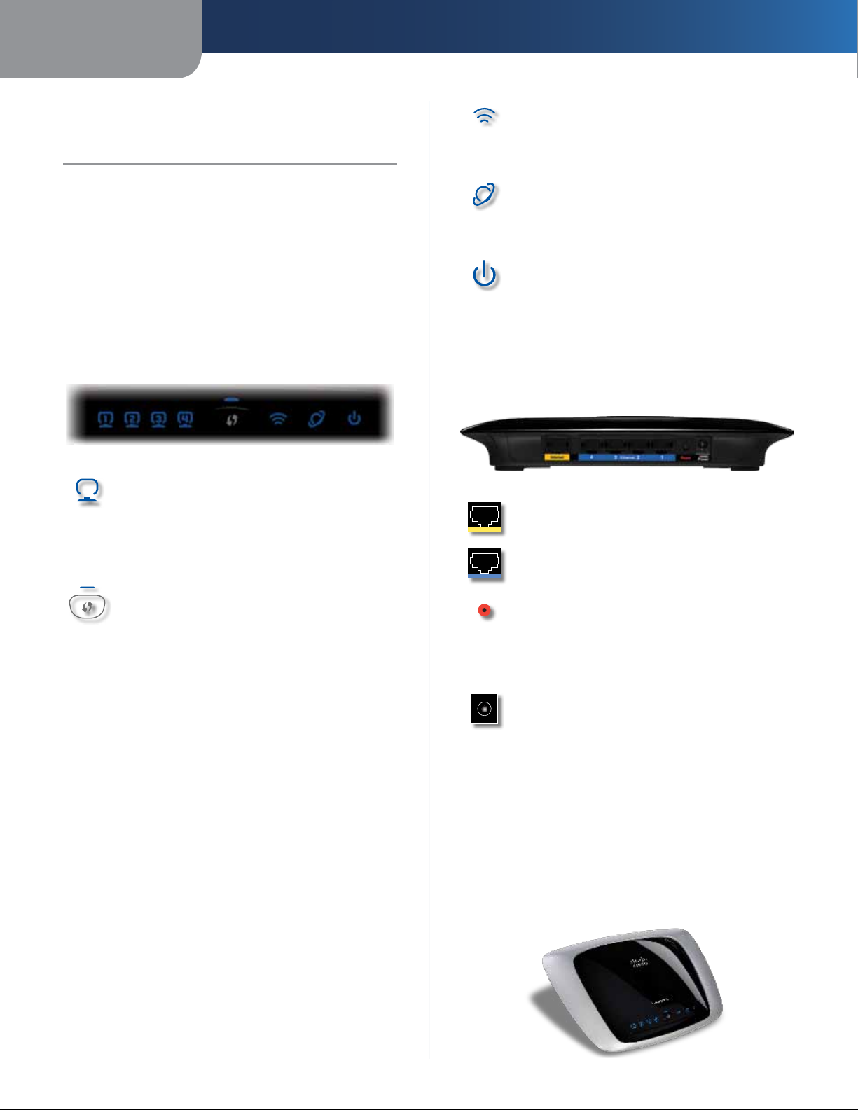
Front Panel
1, 2, 3, 4 (Green/Blue) These numbered LEDs,
corresponding with the numbered ports on the
Router’s back panel, serve two purposes. The
LED is solidly lit when the Router is connected
to a device through that port. It flashes to
indicates network activity.
Wi-Fi Protected Setup Button If you have
client devices, such as wireless adapters, that
support Wi-Fi Protected Setup, then you can
use Wi-Fi Protected Setup to automatically
configure wireless security for your wireless
network(s).
To use Wi-Fi Protected Setup, run the Setup
Wizard, or refer to the “Wireless > Basic Wireless
Settings” section of “Chapter 3: Advanced
Configuration”.
Wi-Fi Protected Setup LED (Blue/Amber) It
lights up blue when wireless security is
enabled. The LED flashes blue for two
minutes during Wi-Fi Protected Setup.
The LED lights up amber if there is an error
during the Wi-Fi Protected Setup process. Make
sure the client device supports Wi-Fi Protected
Setup. Wait until the LED is off, and then try again.
The LED flashes amber when a Wi-Fi Protected
Setup session is active, and a second session
begins. The Router supports one session at a
time. Wait until the LED is off before starting the
next Wi-Fi Protected Setup session.
Wireless (Blue) The Wireless LED lights up
when the wireless feature is enabled. If the LED
is flashing, the Router is actively sending or
receiving data over the network.
Internet (Blue) The Internet LED lights up
when there is a connection made through the
Internet port. A flashing LED indicates network
activity over the Internet port.
Power (Blue) The Power LED lights up and will
stay on while the Router is powered on. When
the Router goes through its self-diagnostic
mode during every boot-up, this LED will flash.
When the diagnostic is complete, the LED will
be solidly lit.
Back Panel
Internet This port is where you will connect
your cable or DSL Internet connection.
4, 3, 2, 1 These ports (4, 3, 2, 1) connect the
Router to computers and other Ethernet
network devices on your wired network.
Reset There are two ways to reset the Router’s
factory defaults. Either press and hold the Reset
Button for approximately five seconds, or restore
the defaults from Administration > Factory
Defaults in the Router’s web-based utility.
Power The Power port is where you will
connect the power adapter.
Placement Positions
There are two ways to physically install the Router. The
first way is to place the Router horizontally on a surface.
The second way is to mount the Router on a wall.
Horizontal Placement
The Router has four rubber feet on its bottom panel. Place
the Router on a level surface near an electrical outlet.
Wireless-N Broadband Router
4
Page 6
Chapter 1
Product Overview
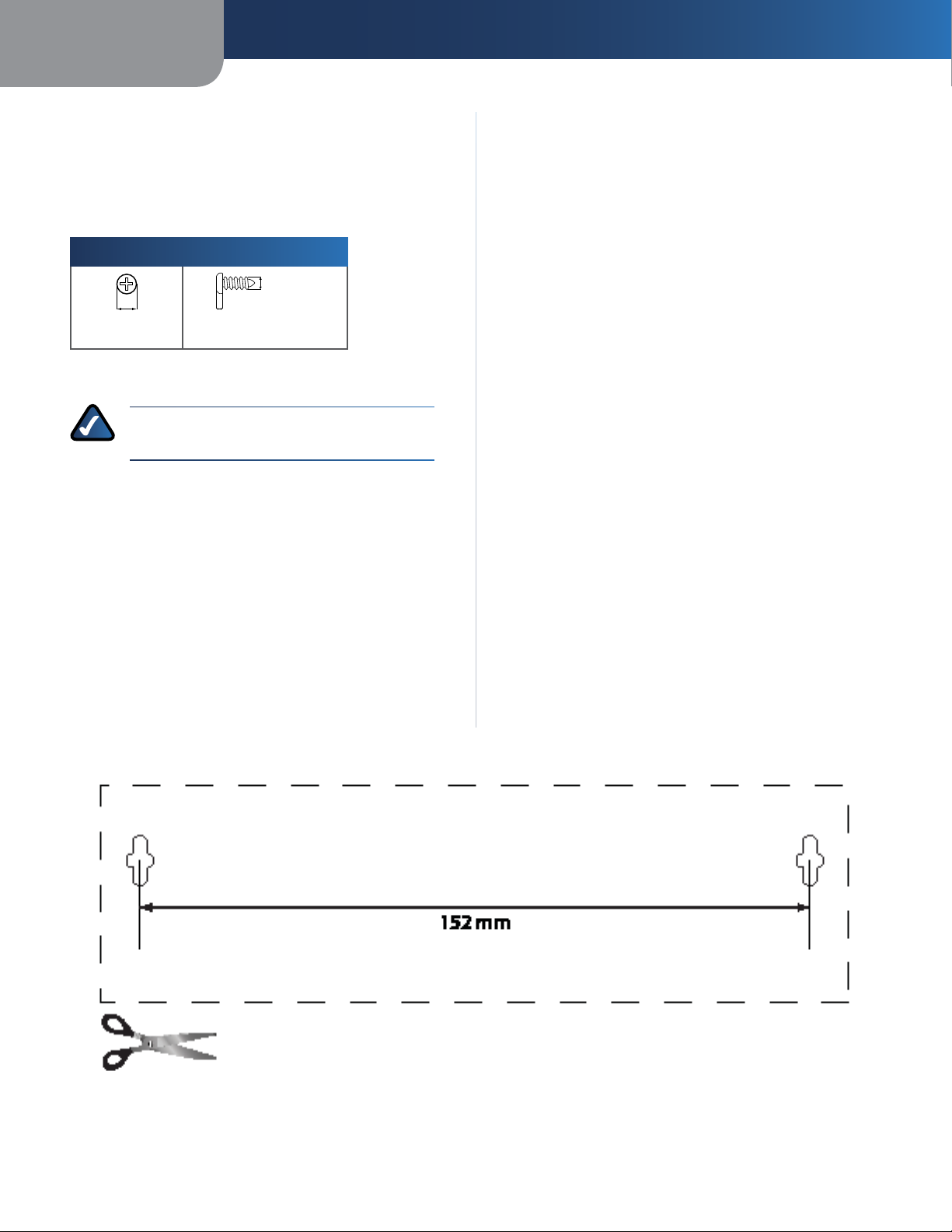
Wall-Mounting Placement
The Router has two wall-mount slots on its bottom
panel. The distance between the slots is 152 mm
(6 inches).
Two screws are needed to mount the Router.
Suggested Mounting Hardware
4-5 mm 1-1.5 mm
†Note: Mounting hardware illustrations are not
true to scale.
NOTE: Linksys is not responsible for damages
incurred by insecure wall-mounting hardware.
2.5-3.0 mm
Follow these instructions:
1. Determine where you want to mount the Router. Make
sure that the wall you use is smooth, flat, dry, and
sturdy. Also make sure the location is within reach of
an electrical outlet.
2. Drill two holes into the wall. Make sure the holes are
152 mm (6 inches) apart.
3. Insert a screw into each hole and leave 3 mm
(0.12 inches) of its head exposed.
4. Maneuver the Router so the wall-mount slots line up
with the two screws.
5. Place the wall-mount slots over the screws and slide
the Router down until the screws fit snugly into the
wall-mount slots.
Wireless-N Broadband Router
Print this page at 100% size.
Cut along the dotted line, and place on the wall to drill precise spacing.
Wall Mounting Template
5
Page 7

Chapter 2
Wireless Security Checklist
Chapter 2: Wireless Security Checklist
Wireless networks are convenient and easy to install, so
homes with high-speed Internet access are adopting them
at a rapid pace. Because wireless networking operates by
sending information over radio waves, it can be more
vulnerable to intruders than a traditional wired network.
Like signals from your cellular or cordless phones, signals
from your wireless network can also be intercepted. Since
you cannot physically prevent someone from connecting
to your wireless network, you need to take some additional
steps to keep your network secure.
1. Change the default wireless
network name or SSID
Wireless devices have a default wireless network name
or Service Set Identifier (SSID) set by the factory. This
is the name of your wireless network, and can be up
to 32 characters in length. Linksys wireless products
use linksys as the default wireless network name. You
should change the wireless network name to something
unique to distinguish your wireless network from other
wireless networks that may exist around you, but do not
use personal information (such as your Social Security
number) because this information may be available for
anyone to see when browsing for wireless networks.
2. Change the default password
For wireless products such as access points and routers,
you will be asked for a password when you want to change
their settings. These devices have a default password set
by the factory. The Linksys default password is admin.
Hackers know these defaults and may try to use them
to access your wireless device and change your network
settings. To thwart any unauthorized changes, customize
the device’s password so it will be hard to guess.
4. Enable encryption
Encryption protects data transmitted over a wireless
network. Wi-Fi Protected Access (WPA/WPA2) and Wired
Equivalent Privacy (WEP) offer different levels of security
for wireless communication.
A network encrypted with WPA/WPA2 is more secure
than a network encrypted with WEP, because WPA/WPA2
uses dynamic key encryption. To protect the information
as it passes over the airwaves, you should enable the
highest level of encryption supported by your network
equipment.
WEP is an older encryption standard and may be the
only option available on some older devices that do not
support WPA.
General Network Security Guidelines
Wireless network security is useless if the underlying
network is not secure.
• Password protect all computers on the network and
individually password protect sensitive files.
• Change passwords on a regular basis.
• Install anti-virus software and personal firewall
software.
• Disable file sharing (peer-to-peer). Some applications
may open file sharing without your consent and/or
knowledge.
Additional Security Tips
• Keep wireless routers, access points, or gateways away
from exterior walls and windows.
• Turn wireless routers, access points, or gateways
off when they are not being used (at night, during
vacations).
• Use strong passphrases that are at least eight characters
in length. Combine letters and numbers to avoid using
standard words that can be found in the dictionary.
3. Enable MAC address filtering
Linksys routers give you the ability to enable Media Access
Control (MAC) address filtering. The MAC address is a
unique series of numbers and letters assigned to every
networking device. With MAC address filtering enabled,
wireless network access is provided solely for wireless
devices with specific MAC addresses. For example, you can
specify the MAC address of each computer in your home
so that only those computers can access your wireless
network.
Wireless-N Broadband Router
WEB: For more information on wireless
security, visit www.linksys.com/security
6
Page 8
Chapter 3
Chapter 3: Advanced Configuration
After setting up the Router with the Setup Wizard (located
on the CD-ROM), the Router will be ready for use. However,
if you’d like to change its advanced settings, use the
Router’s web-based utility. This chapter describes each
web page of the utility and each page’s key functions. You
can access the utility via a web browser on a computer
connected to the Router.
The web-based utility has these main tabs: Setup,
Wireless, Security, Access Restrictions, Applications &
Gaming, Administration, and Status. Additional tabs will
be available after you click one of the main tabs.
NOTE: When first installing the Router, you
should use the Setup Wizard on the Setup
CD-ROM. If you want to configure advanced
settings, use this chapter to learn about the
web-based utility.
Advanced Configuration
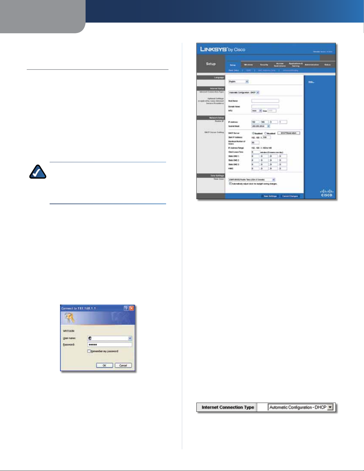
Setup > Basic Setup
How to Access the Web-Based Utility
To access the web-based utility, launch the web browser on
your computer, and enter the Router’s default IP address,
192.168.1.1, in the Address field. Then, press Enter.
A login screen will appear. (Non-Windows XP users will
see a similar screen.) Leave the User name field blank. The
first time you open the Web-based utility, use the default
password admin. (You can set a new password from the
Administration tab’s Management screen.) Click OK to
continue.
Login Screen
Setup > Basic Setup
Internet Setup
The Internet Setup section configures the Router to your
Internet connection. Most of this information can be
obtained through your ISP.
Internet Connection Type
Select the type of Internet connection your ISP provides
from the drop-down menu. These are the available types:
• Automatic Configuration - DHCP
• Static IP
• PPPoE
• PPTP
• L2TP
• Telstra Cable
Automatic Configuration - DHCP
By default, the Router’s Internet Connection Type is set
to Automatic Configuration - DHCP, which should be
kept only if your ISP supports DHCP or you are connecting
through a dynamic IP address. (This option usually applies
to cable connections.)
The first screen that appears is the Basic Setup screen. This
allows you to change the Router’s general settings.
Wireless-N Broadband Router
Internet Connection Type > Automatic Configuration - DHCP
7
Page 9
Chapter 3
Advanced Configuration
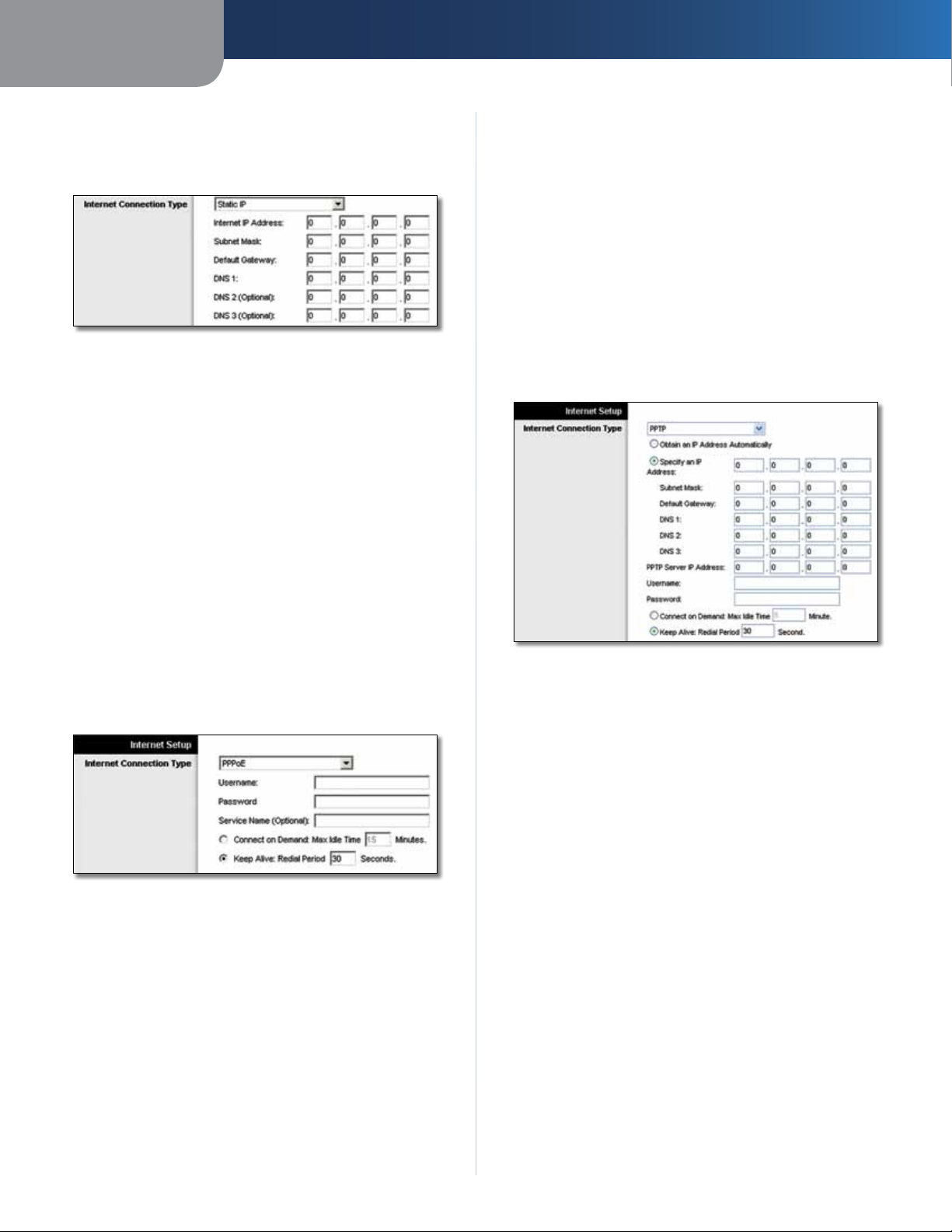
Static IP
If you are required to use a permanent IP address to
connect to the Internet, select Static IP.
Internet Connection Type > Static IP
Internet IP Address This is the Router’s IP address, when
seen from the Internet. Your ISP will provide you with the
IP Address you need to specify here.
Subnet Mask This is the Router’s Subnet Mask, as seen
by users on the Internet (including your ISP). Your ISP will
provide you with the Subnet Mask.
Default Gateway Your ISP will provide you with the IP
address of the ISP server.
DNS 1-3 Your ISP will provide you with at least one DNS
(Domain Name System) server IP address.
before your Internet connection terminates. The default
Max Idle Time is 15 minutes.
Keep Alive: Redial Period If you select this option,
the Router will periodically check your Internet
connection. If you are disconnected, then the Router
will automatically re-establish your connection. To use
this option, select Keep Alive. In the Redial Period field,
you specify how often you want the Router to check
the Internet connection. The default Redial Period is
30 seconds.
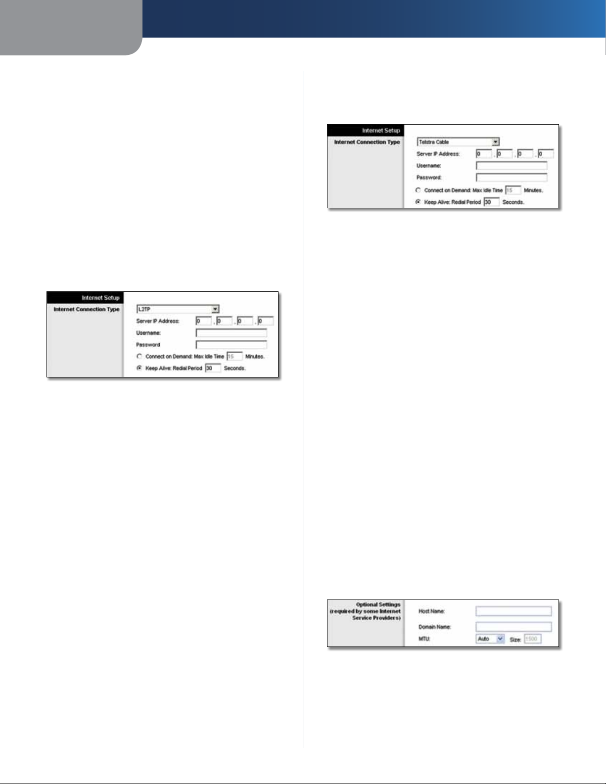
PPTP
Point-to-Point Tunneling Protocol (PPTP) is a service that
applies to connections in Europe only.
PPPoE
Some DSL-based ISPs use PPPoE (Point-to-Point Protocol
over Ethernet) to establish Internet connections. If you are
connected to the Internet through a DSL line, check with
your ISP to see if they use PPPoE. If they do, you will have
to enable PPPoE.
Internet Connection Type > PPPoE
Username and Password Enter the Username and
Password provided by your ISP.
Service Name If provided by your ISP, enter the Service
Name.
Connect on Demand: Max Idle Time You can configure
the Router to cut the Internet connection after it has been
inactive for a specified period of time (Max Idle Time). If
your Internet connection has been terminated due to
inactivity, Connect on Demand enables the Router to
automatically re-establish your connection as soon as you
attempt to access the Internet again. To use this option,
select Connect on Demand. In the Max Idle Time field,
enter the number of minutes you want to have elapsed
Internet Connection Type > PPTP
If your ISP supports DHCP or you are connecting through
a dynamic IP address, then select Obtain an IP Address
Automatically. If you are required to use a permanent IP
address to connect to the Internet, then select Specify an
IP Address. Then configure the following:
• Specify an IP Address This is the Router’s IP address,
as seen from the Internet. Your ISP will provide you
with the IP Address you need to specify here.
• Subnet Mask This is the Router’s Subnet Mask, as
seen by users on the Internet (including your ISP). Your
ISP will provide you with the Subnet Mask.
• Default Gateway Your ISP will provide you with the
IP address of the ISP server.
• DNS 1-3 Your ISP will provide you with at least one
DNS (Domain Name System) server IP address.
PPTP Server IP Address Your ISP will provide you with
the IP address of the PPTP server.
Username and Password Enter the Username and
Password provided by your ISP.
Connect on Demand: Max Idle Time You can configure
the Router to cut the Internet connection after it has been
inactive for a specified period of time (Max Idle Time). If
your Internet connection has been terminated due to
Wireless-N Broadband Router
8
Page 10
Chapter 3
Advanced Configuration
inactivity, Connect on Demand enables the Router to
automatically re-establish your connection as soon as you
attempt to access the Internet again. To use this option,
select Connect on Demand. In the Max Idle Time field,
enter the number of minutes you want to have elapsed
before your Internet connection terminates. The default
Max Idle Time is 15 minutes.
Keep Alive: Redial Period
Router will periodically check your Internet connection. If
you are disconnected, then the Router will automatically
re-establish your connection. To use this option, select
Keep Alive. In the Redial Period field, you specify how often
you want the Router to check the Internet connection. The
default value is 30 seconds.
If you select this option, the
L2TP
L2TP is a service that applies to connections in Israel only.
Internet Connection Type > L2TP
Server IP Address This is the IP address of the L2TP
Server. Your ISP will provide you with the IP Address you
need to specify here.
Username and Password Enter the Username and
Password provided by your ISP.
Connect on Demand: Max Idle Time You can configure
the Router to cut the Internet connection after it has been
inactive for a specified period of time (Max Idle Time). If
your Internet connection has been terminated due to
inactivity, Connect on Demand enables the Router to
automatically re-establish your connection as soon as you
attempt to access the Internet again. To use this option,
select Connect on Demand. In the Max Idle Time field,
enter the number of minutes you want to have elapsed
before your Internet connection terminates. The default
Max Idle Time is 15 minutes.
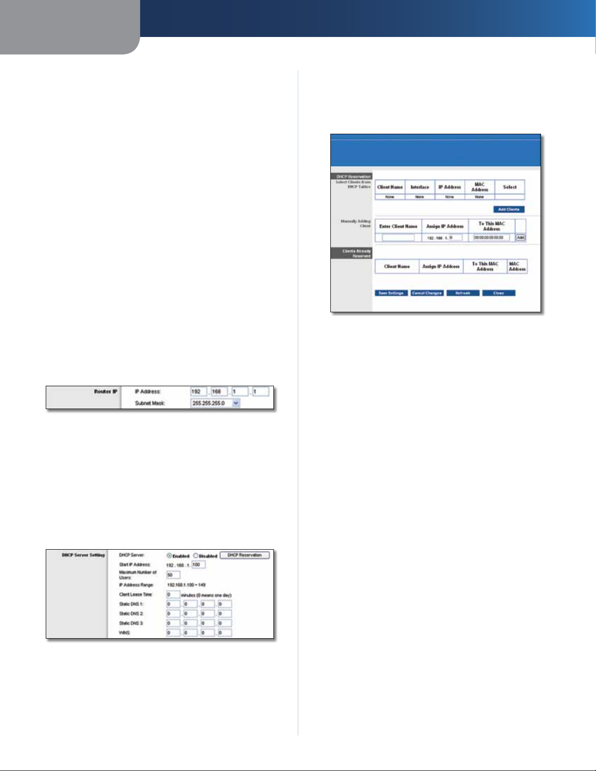
Telstra Cable
Telstra Cable is a service that applies to connections in
Australia only.
Internet Connection Type > Telstra Cable
Server IP Address This is the IP address of the Heartbeat
Server. Your ISP will provide you with the IP Address you
need to specify here.
Username and Password Enter the Username and
Password provided by your ISP.
Connect on Demand: Max Idle Time You can configure
the Router to cut the Internet connection after it has been
inactive for a specified period of time (Max Idle Time). If
your Internet connection has been terminated due to
inactivity, Connect on Demand enables the Router to
automatically re-establish your connection as soon as you
attempt to access the Internet again. To use this option,
select Connect on Demand. In the Max Idle Time field,
enter the number of minutes you want to have elapsed
before your Internet connection terminates. The default
Max Idle Time is 15 minutes.
Keep Alive: Redial Period If you select this option,
the Router will periodically check your Internet
connection. If you are disconnected, then the Router
will automatically re-establish your connection. To use
this option, select Keep Alive. In the Redial Period field,
you specify how often you want the Router to check
the Internet connection. The default Redial Period is
30 seconds.
Optional Settings
Some of these settings may be required by your ISP. Verify
with your ISP before making any changes.
Keep Alive: Redial Period If you select this option,
the Router will periodically check your Internet
connection. If you are disconnected, then the Router
will automatically re-establish your connection. To use
this option, select Keep Alive. In the Redial Period field,
you specify how often you want the Router to check
the Internet connection. The default Redial Period is
30 seconds.
Wireless-N Broadband Router
Optional Settings
Host Name and Domain Name These fields allow you to
supply a host and domain name for the Router. Some ISPs,
usually cable ISPs, require these names as identification.
You may have to check with your ISP to see if your
broadband Internet service has been configured with a
9
Page 11
Chapter 3
Advanced Configuration
host and domain name. In most cases, leaving these fields
blank will work.
MTU MTU is the Maximum Transmission Unit. It specifies
the largest packet size permitted for Internet transmission.
Select Manual if you want to manually enter the largest
packet size that is transmitted. To have the Router select
the best MTU for your Internet connection, keep the
default setting, Auto.
Size When Manual is selected in the MTU field, this option
is enabled. Leave this value in the 1200 to 1500 range. The
default size depends on the Internet Connection Type:
• DHCP, Static IP, or Telstra: 1500
• PPPoE: 1492
• PPTP or L2TP: 1460
Network Setup
The Network Setup section changes the settings on the
network connected to the Router’s Ethernet ports. Wireless
setup is performed through the Wireless tab.
Router IP
This presents both the Router’s IP Address and Subnet
Mask as seen by your network.
Router IP
DHCP Server Setting
The settings allow you to configure the Router’s Dynamic
Host Configuration Protocol (DHCP) server function. The
Router can be used as a DHCP server for your network. A
DHCP server automatically assigns an IP address to each
computer on your network. If you choose to enable the
Router’s DHCP server option, make sure there is no other
DHCP server on your network.
DHCP Reservation
You will see a list of DHCP clients with the following
information: Client Name, Interface, IP Address, and
MAC Address.
DHCP Reservation
• Select Clients from DHCP Table Click the Select
check box to reserve a client’s IP address. Then click
Add Clients.
• Manually Adding Client To manually assign an IP
address, enter the client’s name in the Enter Client
Name field. Enter the IP address you want it to have in
the Assign IP Address field. Enter its MAC address in the
To This MAC Address field. Then click Add.
Clients Already Reserved
A list of DHCP clients and their fixed local IP addresses
will be displayed at the bottom of the screen. If you
want to remove a client from this list, click Remove.
Click Save Settings to apply your changes, or click
Cancel Changes to cancel your changes. To view the
most up-to-date information, click Refresh. To exit this
screen, click Close.
DHCP Server Setting
DHCP Server DHCP is enabled by factory default. If you
already have a DHCP server on your network, or you don’t
want a DHCP server, then select Disabled (no other DHCP
features will be available).
DHCP Reservation Click this button if you want to assign
a fixed local IP address to a MAC address.
Wireless-N Broadband Router
Start IP Address Enter a value for the DHCP server to
start with when is
default IP address is 192.168.1.1, the Start IP Address must
be 192.168.1.2 or greater, but smaller than 192.168.1.253.
The default Starting IP Address is 192.168.1.100
Maximum Number of Users Enter the maximum
number of PCs that you want the DHCP server to assign
IP addresses to. This number cannot be greater than 253.
The default is 50.
IP Address Range Displayed here is the range of available
IP addresses.
Client Lease Time The Client Lease Time is the amount
of time a network user will be allowed connection to the
Router with their current dynamic IP address. Enter the
suing IP addresses. Because the Router’s
.
10
Page 12
Chapter 3
Advanced Configuration
amount of time, in minutes, that the user will be “leased”
this dynamic IP address. After the time is up, the user will
be automatically assigned a new dynamic IP address. The
default is 0 minutes, which means one day.
Static DNS 1-3
the Internet translates domain or website names into
Internet addresses or URLs. Your ISP will provide you with at
least one DNS Server IP Address. If you wish to use another,
enter that IP Address in one of these fields. You can enter up
to three DNS Server IP Addresses here. The Router will use
these for quicker access to functioning DNS servers
WINS The Windows Internet Naming Service (WINS)
manages each PC’s interaction with the Internet. If you
use a WINS server, enter that server’s IP Address here.
Otherwise, leave this blank.
The Domain Name System (DNS) is how
.
Time Setting
Time Zone Select the time zone in which your network
functions from this drop-down menu. (You can even
automatically adjust for daylight saving time.)
Time Setting
Click Save Settings to apply your changes, or click Cancel
Changes to cancel your changes.
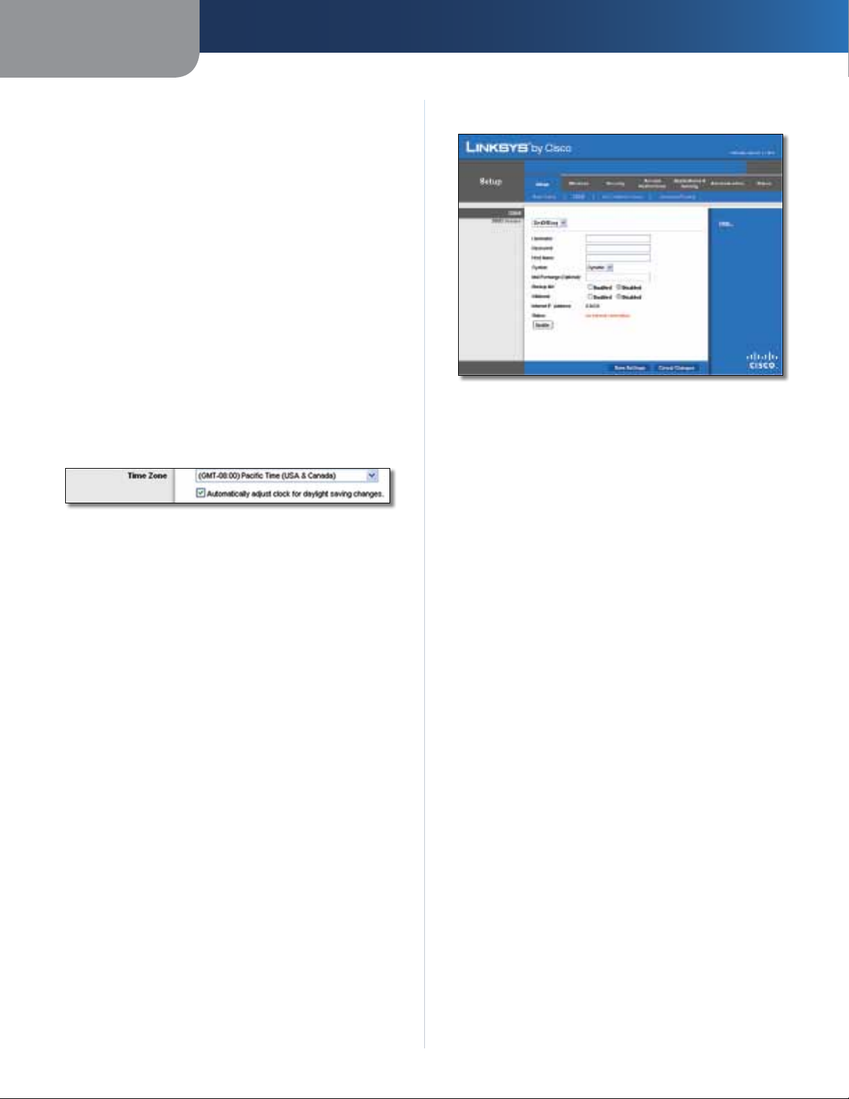
Setup > DDNS
The Router offers a Dynamic Domain Name System (DDNS)
feature. DDNS lets you assign a fixed host and domain
name to a dynamic Internet IP address. It is useful when
you are hosting your own website, FTP server, or other
server behind the Router.
Before you can use this feature, you need to sign
up for DDNS service with a DDNS service provider,
www.dyndns.org or www.TZO.com. If you do not want to
use this feature, keep the default setting, Disabled.
DDNS
DDNS Service
If your DDNS service is provided by DynDNS.org, then
select DynDNS.org from the drop-down menu. If your
DDNS service is provided by TZO, then select TZO.com.
The features available on the DDNS screen will vary,
depending on which DDNS service provider you use.
DynDNS.org
Setup > DDNS > DynDNS
Username Enter the Username for your DDNS account.
Password Enter the Password for your DDNS account.
Host Name The is the DDNS URL assigned by the DDNS
service.
System Select the DynDNS service you use: Dynamic,
Static, or Custom. The default selection is Dynamic.
Mail Exchange (Optional) Enter the address of your mail
exchange server, so e-mails to your DynDNS address go to
your mail server.
Backup MX This feature allows the mail exchange server
to be a backup. To disable this feature, keep the default,
Disabled. To enable the feature, select Enabled. If you
are not sure which setting to select, keep the default,
Disabled.
Wildcard This setting enables or disables wildcards
for your host. For example, if your DDNS address is
myplace.dyndns.org and you enable wildcards, then
x.myplace.dyndns.org will work as well (x is the wildcard).
To disable wildcards, keep the default, Disabled. To enable
wildcards, select Enabled. If you are not sure which setting
to select, keep the default, Disabled.
Internet IP Address The Router’s Internet IP address is
displayed here. Because it is dynamic, it will change.
Status The status of the DDNS service connection is
displayed here.
Update To manually trigger an update, click this button.
Click Save Settings to apply your changes, or click Cancel
Changes to cancel your changes.
Wireless-N Broadband Router
11
Page 13
Chapter 3
Advanced Configuration
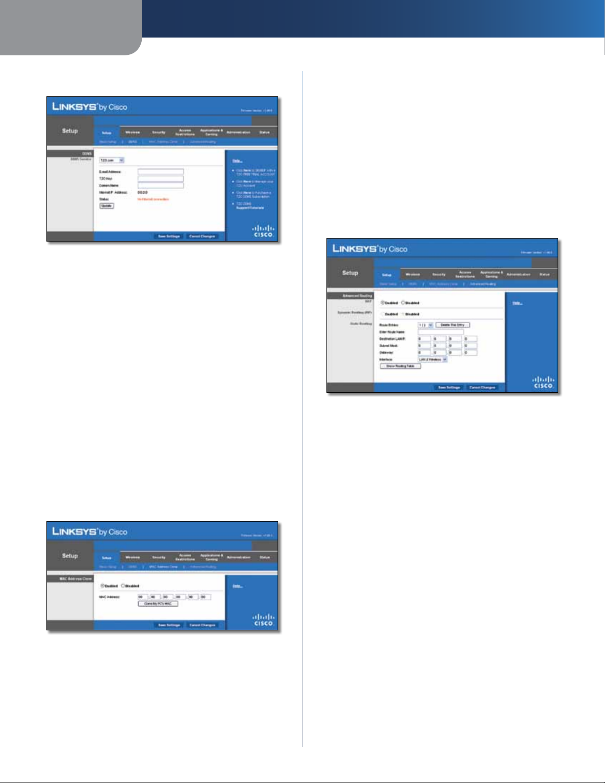
TZO.com
Setup > DDNS > TZO
E-mail Address, TZO Key, and Domain Name Enter the
settings of the account you set up with TZO.
Internet IP Address The Router’s Internet IP address is
displayed here. Because it is dynamic, it will change.
Status The status of the DDNS service connection is
displayed here.
Update To manually trigger an update, click this button.
Clone My PC’s MAC Click this button to clone the MAC
address of the computer you are using.
Click Save Settings to apply your changes, or click Cancel
Changes to cancel your changes.
Setup > Advanced Routing
This screen is used to set up the Router’s advanced
functions. Operating Mode allows you to select the
type(s) of advanced functions you use. Dynamic Routing
automatically adjusts how packets travel on your network.
Static Routing sets up a fixed route to another network
destination.
Click Save Settings to apply your changes, or click Cancel
Changes to cancel your changes.
Setup > MAC Address Clone
A MAC address is a 12-digit code assigned to a unique
piece of hardware for identification. Some ISPs will require
you to register a MAC address in order to access the
Internet. If you do not wish to re-register the MAC address
with your ISP, you may assign the MAC address you have
currently registered with your ISP to the Router with the
MAC Address Clone feature.
Setup > MAC Address Clone
MAC Address Clone
Enabled/Disabled To have the MAC Address cloned,
select Enabled.
MAC Address Enter the MAC Address registered with
your ISP here.
Setup > Advanced Routing
Advanced Routing
NAT
Enabled/Disabled If this Router is hosting your network’s
connection to the Internet, keep the default, Enabled. If
another router exists on your network, select Disabled.
When the NAT setting is disabled, dynamic routing will be
enabled.
Dynamic Routing (RIP)
Enabled/Disabled This feature enables the Router to
automatically adjust to physical changes in the network’s
layout and exchange routing tables with the other router(s).
The Router determines the network packets’ route based
on the fewest number of hops between the source and
the destination. When the NAT setting is enabled, the
Dynamic Routing feature is automatically disabled. When
the NAT setting is disabled, this feature is available. Select
Enabled to use the Dynamic Routing feature.
Static Routing
A static route is a pre-determined pathway that network
information must travel to reach a specific host or network.
Enter the information described below to set up a new
static route.
Wireless-N Broadband Router
12
Page 14
Chapter 3
Advanced Configuration
Route Entries To set up a static route between the Router
and another network, select a number from the dropdown list. Click Delete This Entry to delete a static route.
Enter Route Name Enter a name for the Route here,
using a maximum of 25 alphanumeric characters.
Destination LAN IP The Destination LAN IP is the address
of the remote network or host to which you want to assign
a static route.
Subnet Mask The Subnet Mask determines which
portion of a Destination LAN IP address is the network
portion, and which portion is the host portion.
Gateway This is the IP address of the gateway device that
allows for contact between the Router and the remote
network or host.
Interface This interface tells you whether the Destination
IP Address is on the LAN & Wireless (Ethernet and wireless
networks) or the WAN (Internet).
Click Show Routing Table to view the static routes you
have already set up.
Wi-Fi Protected Setup. Proceed to the “Wi-Fi Protected
Setup” section.
Basic Wireless Settings
Wireless > Basic Wireless Settings (Manual Setup)
Network Mode From this drop-down menu, you can
select the wireless standards running on your network. If
you have Wireless-N, Wireless-G, and Wireless-B devices in
your network, keep the default setting, Mixed. If you have
only Wireless-G and Wireless-B devices in your network,
select BG-Mixed. If you have only Wireless-N devices,
select Wireless-N Only. If you have only Wireless-G
devices, select Wireless-G Only. If you have only Wireless-B
devices, select Wireless-B Only. If you do not have any
wireless devices in your network, select Disabled.
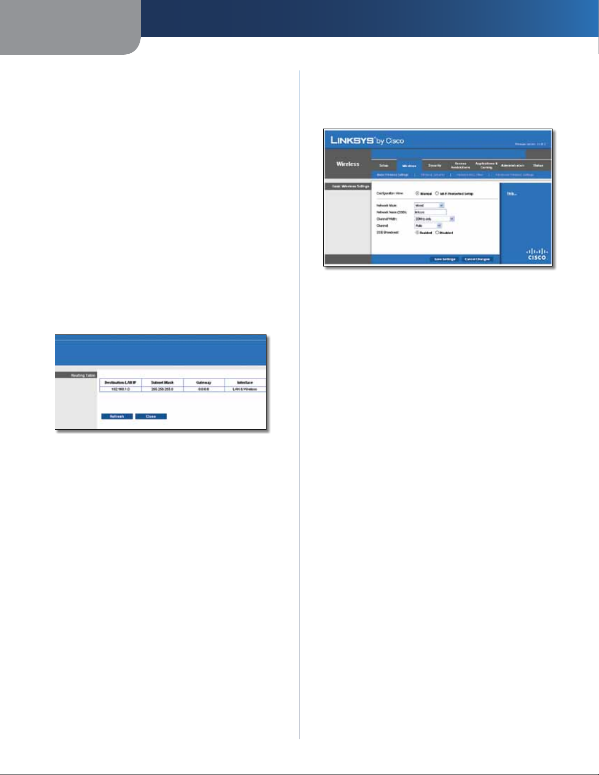
Advanced Routing > Routing Table
Routing Table
For each route, the Destination LAN IP address, Subnet
Mask, Gateway, and Interface are displayed. Click
Refresh to update the information. Click Close to exit
this screen.
Click Save Settings to apply your changes, or click Cancel
Changes to cancel your changes.
Wireless > Basic Wireless Settings
The basic settings for wireless networking are set on this
screen.
There are two ways to configure the Router’s wireless
network(s), manual and Wi-Fi Protected Setup.
Wi-Fi Protected Setup is a feature that makes it easy to set
up your wireless network. If you have client devices, such
as wireless adapters, that support Wi-Fi Protected Setup,
then you can use Wi-Fi Protected Setup.
Configuration View To manually configure your wireless
network, select Manual. Proceed to the “Basic Wireless
Settings” section. To use Wi-Fi Protected Setup, select
Network Name (SSID) The SSID is the network name
shared among all points in a wireless network. The
SSID must be identical for all devices in the wireless
network. It is case-sensitive and must not exceed
32 characters (use any of the characters on the keyboard).
Make sure this setting is the same for all points in your
wireless network. For added security, you should change
the default SSID (linksys) to a unique name.
Channel Width Select Auto if you want the Router
to automatically determine the proper channel width
(20 MHz or 40 MHz) to use, or select 20 MHz only
(default) if you want the Router to operate in Wireless-B
and Wireless-G mode only. For best performance, Auto is
recommended.
Channel Select a channel from 1 to 11, or Auto (default).
SSID Broadcast When wireless clients survey the local
area for wireless networks to associate with, they will
detect the SSID broadcast by the Router. To broadcast the
Router’s SSID, keep the default setting, Enabled. If you
do not want to broadcast the Router’s SSID, then select
Disabled.
Click Save Settings to apply your changes, or click Cancel
Changes to cancel your changes.
Wireless-N Broadband Router
13
Page 15
Chapter 3
Advanced Configuration
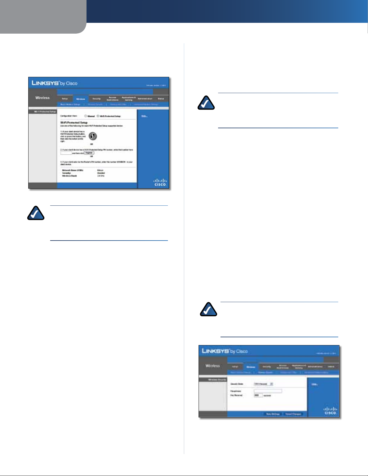
Wi-Fi Protected Setup
There are three methods available. Use the method that
applies to the client device you are configuring.
Wireless > Basic Wireless Settings (Wi-Fi Protected Setup)
NOTE: Wi-Fi Protected Setup configures one
client device at a time. Repeat the instructions
for each client device that supports Wi-Fi
Protected Setup.
2. After the client device has been configured, click
OK. Then refer back to your client device or its
documentation for further instructions.
The Wi-Fi Protected Setup Status, Network Name (SSID),
Security, Encryption, and Passphrase are displayed at the
bottom of the screen.
NOTE: If you have client devices that do not
support Wi-Fi Protected Setup, note the wireless
settings, and then manually configure those
client devices.
Wireless > Wireless Security
The Wireless Security screen configures the security of
your wireless network. There are six wireless security
mode options supported by the Router: WPA Personal,
WPA Enterprise, WPA2 Personal, WPA2 Enterprise, RADIUS,
and WEP. (WPA stands for Wi-Fi Protected Access, which
is a security standard stronger than WEP encryption. WEP
stands for Wired Equivalent Privacy, while RADIUS stands
for Remote Authentication Dial-In User Service.) These
six are briefly discussed here. For detailed instructions
on configuring wireless security for the Router, refer to
“Chapter 2: Wireless Security.”
Wireless Security
Method #1
Use this method if your client device has a Wi-Fi Protected
Setup button.
1. Click or press the Wi-Fi Protected Setup button on
the client device.
2. Click the Wi-Fi Protected Setup button on this
screen.
3. After the client device has been configured, click
OK. Then refer back to your client device or its
documentation for further instructions.
Method #2
Use this method if your client device has a Wi-Fi Protected
Setup PIN number.
1. Enter the PIN number in the field on this screen.
2. Click Register.
3. After the client device has been configured, click
OK. Then refer back to your client device or its
documentation for further instructions.
Method #3
Use this method if your client device asks for the Router’s
PIN number.
1. Enter the PIN number listed on this screen. (It is also
listed on the label on the bottom of the Router.)
Security Mode
Select the security method for your wireless network. If
you do not want to use wireless security, keep the default,
Disabled.
WPA Personal
NOTE: If you are using WPA, always remember
that each device in your wireless network MUST
use the same WPA method and shared key, or
else the network will not function properly.
Security Mode > WPA Personal
Passphrase Enter a Passphrase of 8-63 characters.
Wireless-N Broadband Router
14
Page 16
Chapter 3
Advanced Configuration
Key Renewal Enter a Key Renewal period, which instructs
the Router how often it should change the encryption keys.
The default Group Key Renewal period is 3600 seconds.
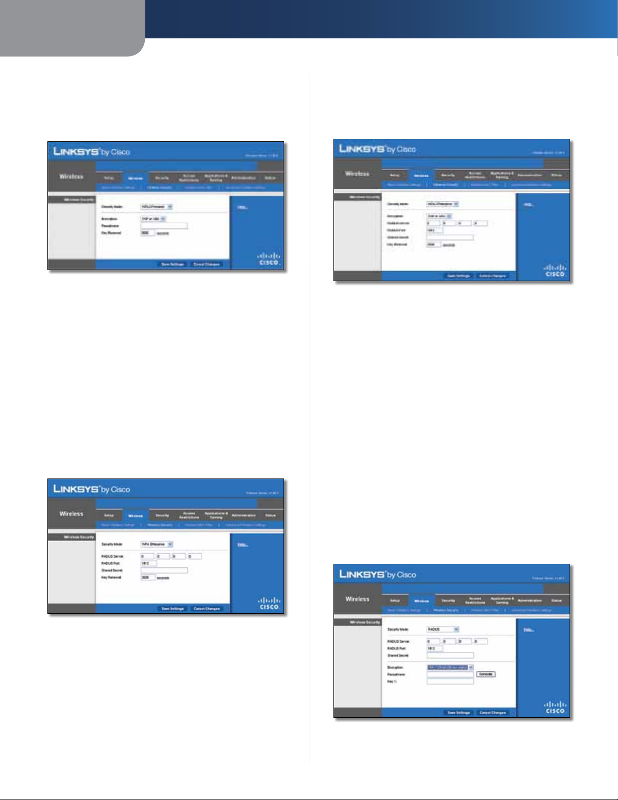
WPA2 Personal
Security Mode > WPA2 Personal
Encryption WPA2 supports two encryption methods,
TKIP and AES, with dynamic encryption keys. Select the
type of algorithm, AES or TKIP or AES. The default is TKIP
or AES.
Passphrase Enter a Passphrase of 8-63 characters.
Key Renewal Enter a Key Renewal period, which instructs
the Router how often it should change the encryption keys.
The default Group Key Renewal period is 3600 seconds.
WPA Enterprise
This option features WPA used in coordination with a
RADIUS server. (This should only be used when a RADIUS
server is connected to the Router.)
WPA2 Enterprise
This option features WPA2 used in coordination with a
RADIUS server. (This should only be used when a RADIUS
server is connected to the Router.)
Security Mode > WPA2 Enterprise
Encryption WPA2 supports two encryption methods,
TKIP and AES, with dynamic encryption keys. Select the
type of algorithm, AES or TKIP or AES. The default is TKIP
or AES.
RADIUS Server Enter the IP Address of the RADIUS
server.
RADIUS Port Enter the port number of the RADIUS
server. The default value is 1812.
Shared Secret Enter the key shared between the Router
and the server.
Key Renewal Enter a Key Renewal period, which instructs
the Router how often it should change the encryption
keys. The default Key Renewal period is 3600 seconds.
Security Mode > WPA Enterprise
RADIUS Server Enter the IP Address of the RADIUS
server.
RADIUS Port Enter the port number of the RADIUS
server. The default value is 1812.
Shared Secret Enter the key shared between the Router
and the server.
Key Renewal Enter a Key Renewal period, which instructs
the Router how often it should change the encryption
keys. The default Key Renewal period is 3600 seconds.
Wireless-N Broadband Router
RADIUS
This option features WEP used in coordination with a
RADIUS server. (This should only be used when a RADIUS
server is connected to the Router.)
Security Mode > RADIUS
15
Page 17
Chapter 3
IMPORTANT: If you are using WEP encryption,
always remember that each device in your
wireless network MUST use the same WEP
encryption method and encryption key, or else
your wireless network will not function properly.
RADIUS Server Enter the IP Address of the RADIUS
server.
RADIUS Port Enter the port number of the RADIUS
server. The default value is 1812.
Shared Secret Enter the key shared between the Router
and the server.
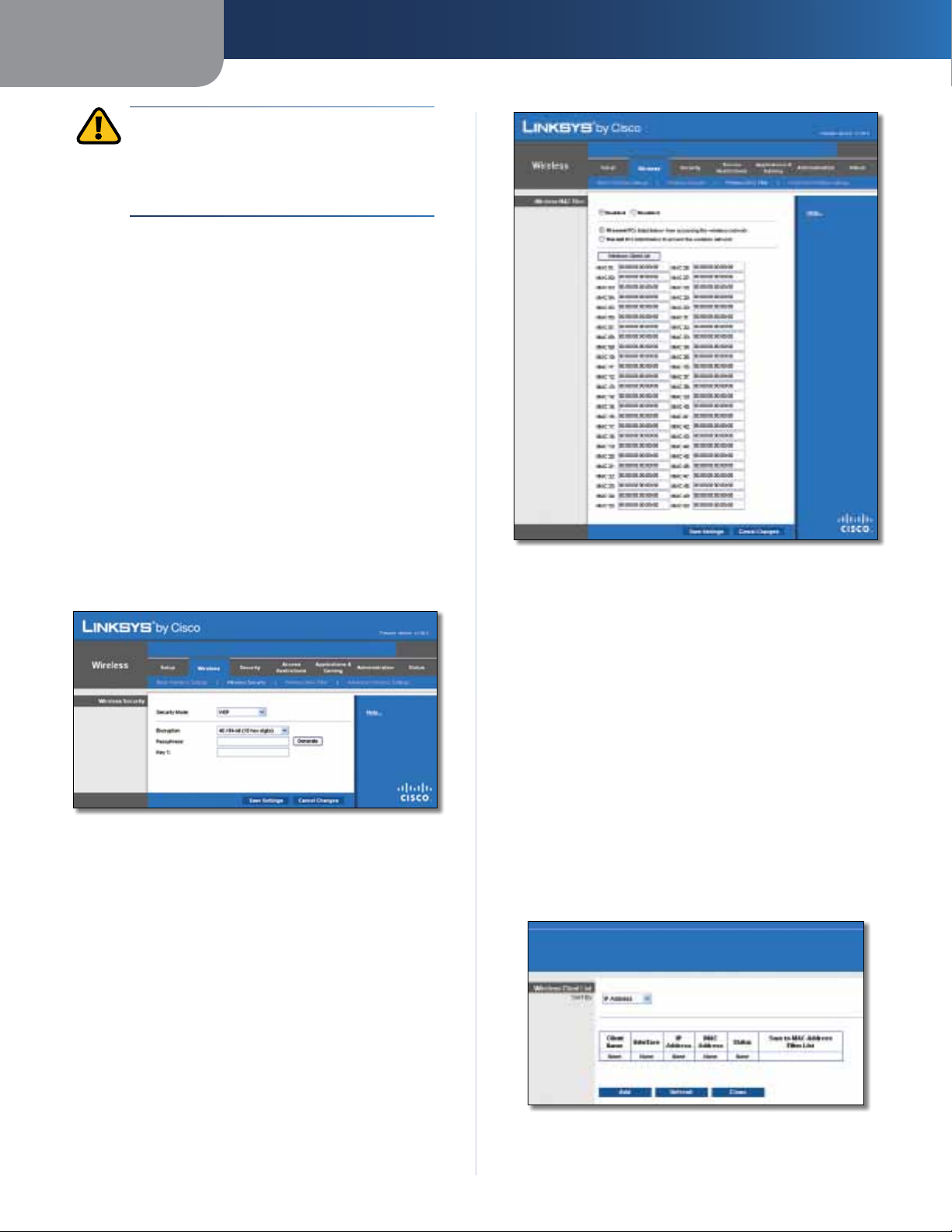
Encryption Select a level of WEP encryption,
40/64 bits (10 hex digits) or 104/128 bits (26 hex digits).
The default is 40/64 bits (10 hex digits).
Passphrase Enter a Passphrase to automatically generate
WEP keys. Then click Generate.
Key 1 If you did not enter a Passphrase, enter the WEP
key manually.
Advanced Configuration
WEP
WEP is a basic encryption method, which is not as secure
as WPA.
Security Mode > WEP
Encryption Select a level of WEP encryption,
40/64 bits (10 hex digits) or 104/128 bits (26 hex digits).
The default is 40/64 bits (10 hex digits).
Passphrase Enter a Passphrase to automatically generate
WEP keys. Then click Generate.
Key 1 If you did not enter a Passphrase, enter the WEP
key manually.
Wireless > Wireless MAC Filter
Wireless MAC Filter
Enabled/Disabled
either permitting or blocking access, select Enabled. If you
do not wish to filter users by MAC Address, keep the default
setting, Disabled
Access Restriction
Prevent Select this to block wireless access by MAC
Address. This option is selected by default.
Permit Select this to allow wireless access by MAC
Address. This option is not selected by default.
MAC Address Filter List
Wireless Client List Click this to open the Wireless Client
List screen.
To filter wireless users by MAC Address,
.
Click Save Settings to apply your changes, or click Cancel
Changes to cancel your changes.
Wireless > Wireless MAC Filter
Wireless access can be filtered by using the MAC addresses of
the wireless devices transmitting within your network’s radius.
Wireless-N Broadband Router
Wireless Client List
16
Page 18
Chapter 3
Advanced Configuration
Wireless Client List
This screen shows computers and other devices on
the wireless network. The list can be sorted by Client
Name, Interface, IP Address, MAC Address, and Status.
Select Save to MAC Address Filter List for any device
you want to add to the MAC Address Filter List. Then
click Add.
To retrieve the most up-to-date information, click
Refresh. To exit this screen and return to the Wireless
MAC Filter screen, click Close.
MAC 01-50 Enter the MAC addresses of the devices
whose wireless access you want to block or allow.
Click Save Settings to apply your changes, or click Cancel
Changes to cancel your changes.
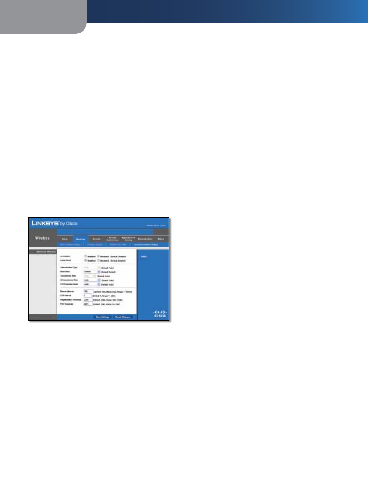
Wireless > Advanced Wireless Settings
This Advanced Wireless Settings screen is used to set up
the Router’s advanced wireless functions. These settings
should only be adjusted by an expert administrator as
incorrect settings can reduce wireless performance.
With Shared Key authentication, the sender and recipient
use a WEP key for authentication. Select Shared Key to
only use Shared Key authentication.
Basic Rate The Basic Rate setting is not actually one rate
of transmission but a series of rates at which the Router
can transmit. The Router will advertise its Basic Rate to the
other wireless devices in your network, so they know which
rates will be used. The Router will also advertise that it will
automatically select the best rate for transmission. The
default setting is Default, when the Router can transmit
at all standard wireless rates (1-2Mbps, 5.5Mbps, 11Mbps,
18Mbps, and 24Mbps). Other options are 1-2Mbps, for
use with older wireless technology, and All, when the
Router can transmit at all wireless rates. The Basic Rate
is not the actual rate of data transmission. If you want to
specify the Router’s rate of data transmission, configure
the Transmission Rate setting.
Transmission Rate The rate of data transmission should
be set depending on the speed of your wireless network.
You can select from a range of transmission speeds, or you
can select Auto to have the Router automatically use the
fastest possible data rate and enable the Auto-Fallback
feature. Auto-Fallback will negotiate the best possible
connection speed between the Router and a wireless
client. The default is Auto.
Wireless > Advanced Wireless Settings
Advanced Wireless
AP Isolation This isolates all wireless clients and wireless
devices on your network from each other. Wireless devices
will be able to communicate with the Router but not
with each other. To use this function, select Enabled. AP
Isolation is disabled by default.
Frame Burst Enabling this option should provide your
network with greater performance, depending on the
manufacturer of your wireless products. To use this option,
keep the default, Enabled. Otherwise, select Disabled.
Authentication Type The default is set to Auto, which
allows either Open System or Shared Key authentication
to be used. With Open System authentication, the sender
and the recipient do NOT use a WEP key for authentication.
N Transmission Rate The rate of data transmission
should be set depending on the speed of your Wireless-N
networking. You can select from a range of transmission
speeds, or you can select Auto to have the Router
automatically use the fastest possible data rate and enable
the Auto-Fallback feature. Auto-Fallback will negotiate the
best possible connection speed between the Router and a
wireless client. The default is Auto.
CTS Protection Mode The Router will automatically
use CTS (Clear-To-Send) Protection Mode when your
Wireless-N and Wireless-G products are experiencing
severe problems and are not able to transmit to the
Router in an environment with heavy 802.11b traffic. This
function boosts the Router’s ability to catch all WirelessN and Wireless-G transmissions but will severely decrease
performance. The default is Auto.
Beacon Interval Enter a value between 1 and 65,535
milliseconds. The Beacon Interval value indicates the
frequency interval of the beacon. A beacon is a packet
broadcast by the Router to synchronize the wireless
network. The default value is 100.
DTIM Interval This value, between 1 and 255, indicates
the interval of the Delivery Traffic Indication Message
(DTIM). A DTIM field is a countdown field informing
clients of the next window for listening to broadcast
and multicast messages. When the Router has buffered
broadcast or multicast messages for associated clients, it
sends the next DTIM with a DTIM Interval value. Its clients
Wireless-N Broadband Router
17
Page 19
Chapter 3
Advanced Configuration
hear the beacons and awaken to receive the broadcast
and multicast messages. The default value is 1.
Fragmentation Threshold This value specifies the
maximum size for a packet before data is fragmented
into multiple packets. If you experience a high packet
error rate, you may slightly increase the Fragmentation
Threshold. Setting the Fragmentation Threshold too low
may result in poor network performance. Only minor
reduction of the default value is recommended. In most
cases, it should remain at its default value of 2346.
RTS Threshold Should you encounter inconsistent data
flow, only minor reduction of the default value, 2347, is
recommended. If a network packet is smaller than the
preset RTS threshold size, the RTS/CTS mechanism will
not be enabled. The Router sends Request to Send (RTS)
frames to a particular receiving station and negotiates
the sending of a data frame. After receiving an RTS, the
wireless station responds with a Clear to Send (CTS) frame
to acknowledge the right to begin transmission. The RTS
Threshold value should remain at its default value of
2347.
Click Save Settings to apply your changes, or click Cancel
Changes to cancel your changes.
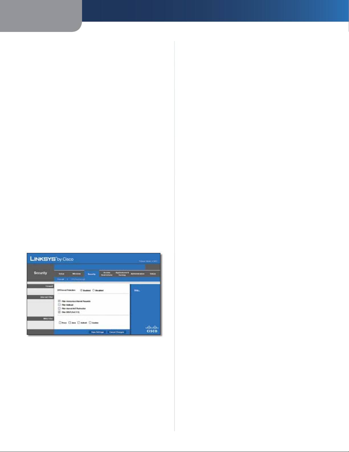
Security > Firewall
The Firewall screen is used to configure a firewall that can
filter out various types of unwanted traffic on the Router’s
local network.
Deselect the feature to allow anonymous Internet
requests
Filter Multicast Multicasting allows for multiple
transmissions to specific recipients at the same time. If
multicasting is permitted, then the Router will allow IP
multicast packets to be forwarded to the appropriate
computers. Select this feature to filter multicasting. This
feature is not selected by default.
Filter Internet NAT Redirection This feature uses port
forwarding to block access to local servers from local
networked computers. Select this feature to filter Internet
NAT redirection. It is not selected by default.
Filter IDENT (Port 113) This feature keeps port 113 from
being scanned by devices outside of your local network.
This feature is selected by default. Deselect this feature to
disable it.
.
Web Filter
Proxy Use of WAN proxy servers may compromise the
Gateway’s security. Denying Proxy will disable access to
any WAN proxy servers. Select this feature to enable proxy
filtering. Deselect the feature to allow proxy access
Java Java is a programming language for websites. If you
deny Java, you run the risk of not having access to Internet
sites created using this programming language. Select
this feature to enable Java filtering. Deselect the feature
to allow Java usage
ActiveX ActiveX is a programming language for websites.
If you deny ActiveX, you run the risk of not having access to
Internet sites created using this programming language.
Select this feature to enable ActiveX filtering. Deselect the
feature to allow ActiveX usage
.
.
.
Security > Firewall
Firewall
SPI Firewall Protection To use firewall protection,
keep the default selection, Enabled. To turn off firewall
protection, select Disabled.
Internet Filter
Filter Anonymous Internet Requests This feature
makes it more difficult for outside users to work their
way into your network. This feature is selected by default.
Wireless-N Broadband Router
Cookies A cookie is data stored on your computer and
used by Internet sites when you interact with them. Select
this feature to filter cookies. Deselect the feature to allow
cookie usage
Click Save Settings to apply your changes, or click Cancel
Changes to cancel your changes.
.
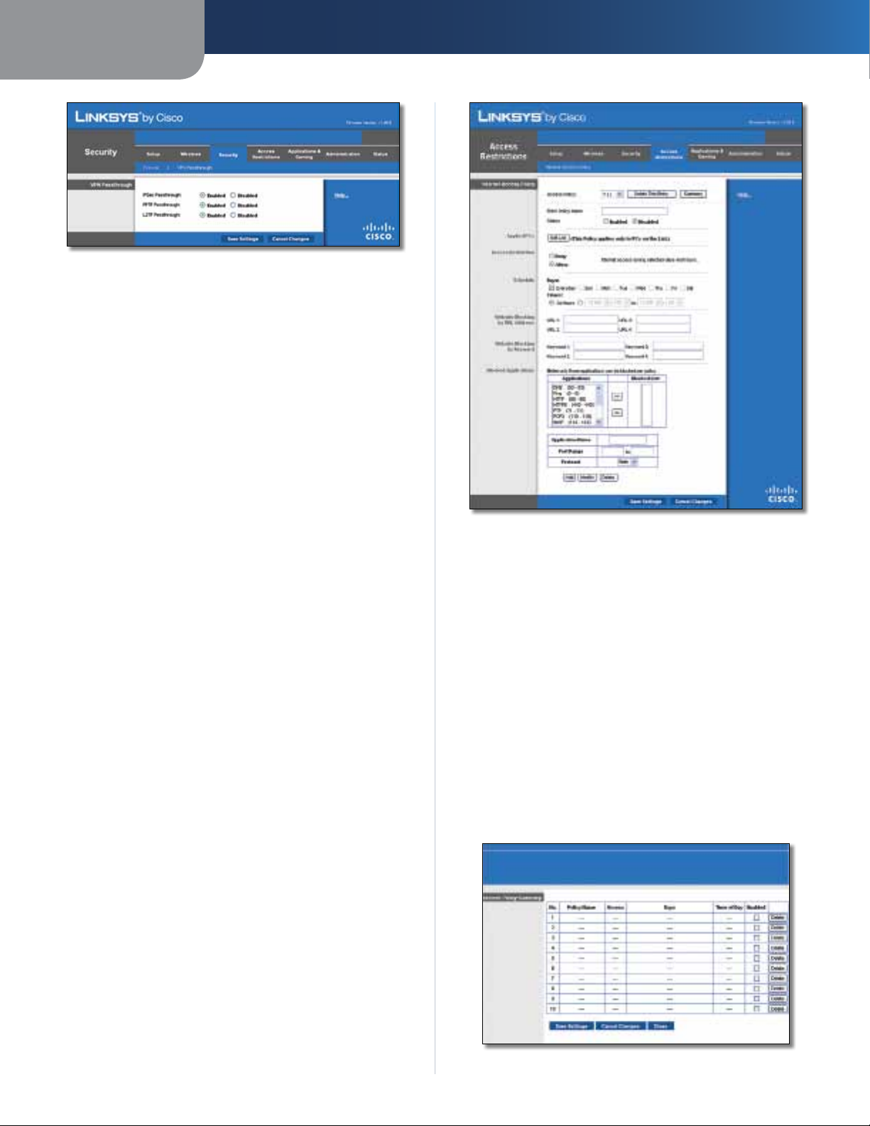
Security > VPN Passthrough
The VPN Passthrough screen allows you to enable VPN
tunnels using IPSec, PPTP, or L2TP protocols to pass through
the Router’s firewall.
18
Page 20
Chapter 3
Security > VPN Passthrough
VPN Passthrough
IPSec Passthrough Internet Protocol Security (IPSec) is
a suite of protocols used to implement secure exchange
of packets at the IP layer. To allow IPSec tunnels to pass
through the Router, keep the default, Enabled.
PPTP Passthrough Point-to-Point Tunneling Protocol
(PPTP) allows the Point-to-Point Protocol (PPP) to be
tunneled through an IP network. To allow PPTP tunnels to
pass through the Router, keep the default, Enabled.
Advanced Configuration
L2TP Passthrough Layer 2 Tunneling Protocol is the
method used to enable Point-to-Point sessions via the
Internet on the Layer 2 level. To allow L2TP tunnels to pass
through the Router, keep the default, Enabled.
Click Save Settings to apply your changes, or click Cancel
Changes to cancel your changes.
Access Restrictions > Internet Access
The Internet Access screen allows you to block or allow
specific kinds of Internet usage and traffic, such as Internet
access, designated services, and websites during specific
days and times.
Access Restrictions > Internet Access
Internet Access Policy
Access Policy Access can be managed by a policy. Use the
settings on this screen to establish an access policy (after
Save Settings is clicked). Selecting a policy from the dropdown menu will display that policy’s settings. To delete a
policy, select that policy’s number and click Delete This
Policy. To view all the policies, click Summary.
Summary
The policies are listed with the following information: No.,
Policy Name, Access, Days, Time, and status (Enabled). To
enable a policy, select Enabled. To delete a policy, click
Delete. Click Save Settings to save your changes, or click
Cancel Changes to cancel your changes. To return to the
Internet Access Policy screen, click Close.
Wireless-N Broadband Router
Summary
19
Page 21
Chapter 3
Advanced Configuration
Status Policies are disabled by default. To enable a policy,
select the policy number from the drop-down menu, and
select Enabled.
To create a policy, follow steps 1-11. Repeat these steps to
create additional policies, one at a time.
1. Select a number from the Access Policy drop-down
menu.
2. Enter a Policy Name in the field provided.
3. To enable this policy, select Enabled.
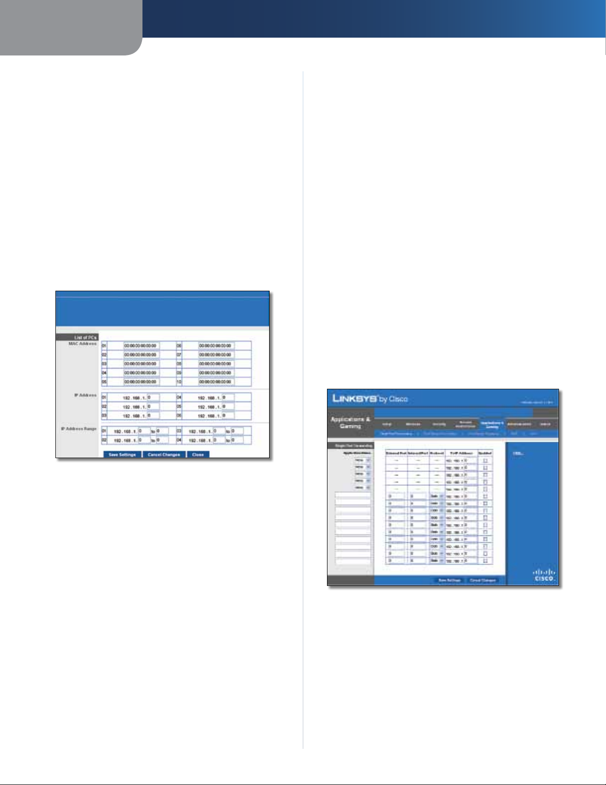
4. Click Edit List to select which PCs will be affected by
the policy. The List of PCs screen appears. You can
select a PC by MAC address or IP address. You can also
enter a range of IP addresses if you want this policy to
affect a group of PCs. After making your changes, click
Save Settings to apply your changes, or click Cancel
Changes to cancel your changes. Then click Close.
10. If the application you want to block is not listed or you
want to edit a service’s settings, enter the application’s
name in the Application Name field. Enter its range
in the Port Range fields. Select its protocol from the
Protocol drop-down menu. Then click Add.
To modify a service, select it from the Application list.
Change its name, port range, and/or protocol setting.
Then click Modify.
To delete a service, select it from the Application list.
Then click Delete.
11. Click Save Settings to save the policy’s settings. To
cancel the policy’s settings, click Cancel Changes.
Applications and Gaming > Single Port Forwarding
The Single Port Forwarding screen allows you to customize
port services for common applications on this screen.
When users send these types of requests to your network via
the Internet, the Router will forward those requests to the
appropriate servers (computers). Before using forwarding,
you should assign static IP addresses to the designated
servers (use the DHCP Reservation feature on the Basic Setup
screen).
List of PCs
5. Select the appropriate option, Deny or Allow,
depending on whether you want to block or allow
Internet access for the PCs you listed on the List of PCs
screen.
6. Decide which days and what times you want this policy
to be enforced. Select the individual days during which
the policy will be in effect, or select Everyday. Then
enter a range of hours and minutes during which the
policy will be in effect, or select 24 Hours.
7. You can block websites with specific URL addresses.
Enter each URL in a separate URL field.
8. You can also block websites using specific keywords.
Enter each keyword in a separate Keyword field.
9. You can filter access to various services accessed over
the Internet, such as FTP or telnet. (You can block up to
three applications per policy.)
From the Applications list, select the application you
want to block. Then click the >> button to move it to
the Blocked List. To remove an application from the
Blocked List, select it and click the << button.
Applications and Gaming > Single Port Forwarding
Single Port Forwarding
Common applications are available for the first five
entries. Select the appropriate application. Then enter the
IP address of the server that should receive these requests.
Select Enabled to activate this entry.
For additional applications, complete the following fields:
Application Name Enter the name you wish to give the
application. Each name can be up to 12 characters.
Wireless-N Broadband Router
20
Page 22
Chapter 3
Advanced Configuration
External Port Enter the external port number used by
the server or Internet application. Check with the Internet
application documentation for more information.
Internal Port Enter the internal port number used by
the server or Internet application. Check with the Internet
application documentation for more information.
Protocol Select the protocol used for this application,
either TCP or UDP, or Both.
To IP Address For each application, enter the IP address
of the PC that should receive the requests. If you assigned
a static IP address to the PC, then you can click DHCP
Reservation on the Basic Setup screen to look up its static
IP address.
Enabled For each application, select Enabled to enable
port forwarding.
Click Save Settings to apply your changes, or click Cancel
Changes to cancel your changes.
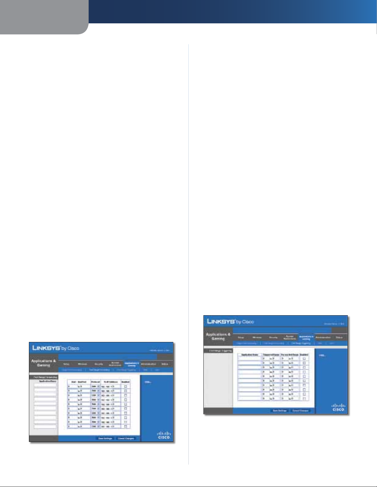
Applications and Gaming > Port Range Forwarding
The Port Range Forwarding screen allows you to set up
public services on your network, such as web servers,
ftp servers, e-mail servers, or other specialized Internet
applications. (Specialized Internet applications are any
applications that use Internet access to perform functions
such as videoconferencing or online gaming. Some Internet
applications may not require any forwarding.)
When users send these types of requests to your network via
the Internet, the Router will forward those requests to the
appropriate servers (computers). Before using forwarding,
you should assign static IP addresses to the designated
servers (use the DHCP Reservation feature on the Basic Setup
screen).
Port Range Forwarding
To forward a port, enter the information on each line for
the criteria required.
Application Name In this field, enter the name you
wish to give the application. Each name can be up to 12
characters.
Start~End Port Enter the number or range of port(s)
used by the server or Internet applications. Check
with the Internet application documentation for more
information.
Protocol Select the protocol used for this application,
either TCP or UDP, or Both.
To IP Address For each application, enter the IP address
of the PC running the specific application. If you assigned
a static IP address to the PC, then you can click DHCP
Reservation on the Basic Setup screen to look up its static
IP address.
Enabled Select Enabled to enable port forwarding for
the applications you have defined.
Click Save Settings to apply your changes, or click Cancel
Changes to cancel your changes.
Applications & Gaming > Port Range Triggering
The Port Range Triggering screen allows the Router to
watch outgoing data for specific port numbers. The IP
address of the computer that sends the matching data is
remembered by the Router, so that when the requested
data returns through the Router, the data is pulled back
to the proper computer by way of IP address and port
mapping rules.
If you need to forward all ports to one computer, click the
DMZ tab.
Applications and Gaming > Port Range Forwarding
Wireless-N Broadband Router
Applications and Gaming > Port Range Triggering
Port Range Triggering
Application Name Enter the application name of the
trigger.
21
Page 23
Chapter 3
Advanced Configuration
Triggered Range For each application, enter the starting
and ending port numbers of the triggered port number
range. Check with the Internet application documentation
for the port number(s) needed.
Forwarded Range For each application, enter the starting
and ending port numbers of the forwarded port number
range. Check with the Internet application documentation
for the port number(s) needed.
Enabled Select Enabled to enable port triggering for the
applications you have defined.
Click Save Settings to apply your changes, or click Cancel
Changes to cancel your changes.
Applications and Gaming > DMZ
The DMZ feature allows one network computer to be
exposed to the Internet for use of a special-purpose
service such as Internet gaming or videoconferencing.
DMZ hosting forwards all the ports at the same time to
one PC. The Port Range Forwarding feature is more secure
because it only opens the ports you want to have opened,
while DMZ hosting opens all the ports of one computer,
exposing the computer to the Internet.
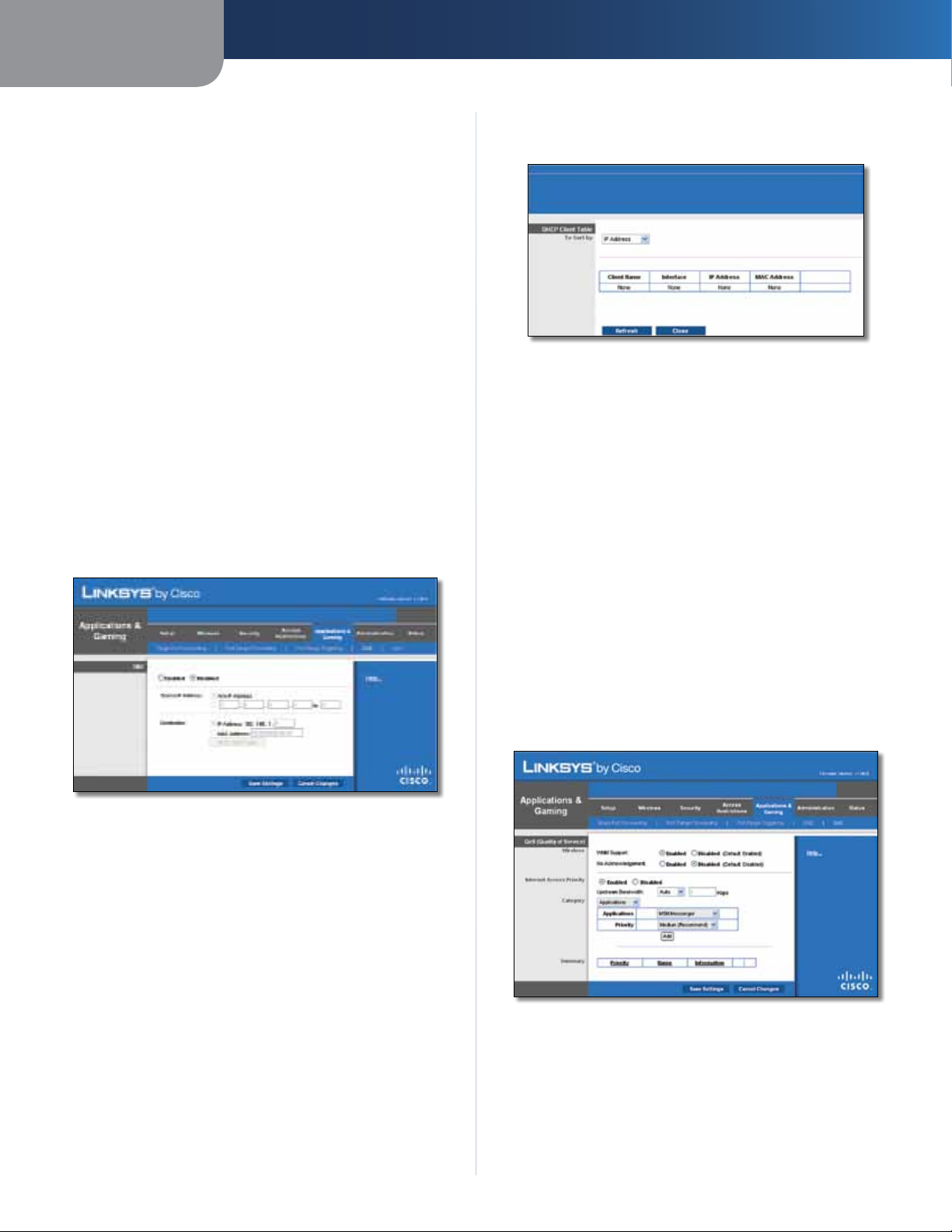
address in the field provided. To retrieve this information,
click DHCP Client Table.
DMZ > DHCP Client Table
DHCP Client Table
The DHCP Client Table lists computers and other
devices that have been assigned IP addresses by the
Router. The list can be sorted by Client Name, Interface,
IP Address, MAC Address, and Expired Time (how much
time is left for the current IP address). To select a DHCP
client, click Select. To retrieve the most up-to-date
information, click Refresh. To exit this screen and
return to the DMZ screen, click Close.
Applications and Gaming > DMZ
DMZ
Any PC whose port is being forwarded must have its DHCP
client function disabled and should have a new static IP
address assigned to it because its IP address may change
when using the DHCP function.
Enabled/Disabled To disable DMZ hosting, select
Disabled. To expose one PC, select Enabled. Then
configure the following settings:
Source IP Address If you want any IP address to be the
source, select Any IP Address. If you want to specify an IP
address or range of IP addresses as the designated source,
select and complete the IP address range fields.
Destination If you want to specify the DMZ host by IP
address, select IP Address and enter the IP address in
the field provided. If you want to specify the DMZ host
by MAC address, select MAC Address and enter the MAC
Click Save Settings to apply your changes, or click Cancel
Changes to cancel your changes.
Applications and Gaming > QoS
Quality of Service (QoS) ensures better service to
high-priority types of network traffic, which may
involve demanding, real-time applications, such as
videoconferencing.
Applications and Gaming > QoS
QoS (Quality of Service)
Wireless
You can configure the support and No Acknowledgement
settings in this section.
Wireless-N Broadband Router
22
Page 24
Chapter 3
Advanced Configuration
WMM Support If you have other devices that support Wi-
Fi Multimedia (WMM) on your network, keep the default,
Enabled. Otherwise, select Disabled.
No Acknowledgement If you want to disable the Router’s
Acknowledgement feature, so the Router will not re-send
data if an error occurs, then select Enabled. Otherwise,
keep the default, Disabled.
Internet Access Priority
In this section, you can set the bandwidth priority for a
variety of applications and devices. There are four levels
priority: High, Medium, Normal, or Low. When you set
priority, do not set all applications to High, because this will
defeat the purpose of allocating the available bandwidth.
If you want to select below normal bandwidth, select Low.
Depending on the application, a few attempts may be
needed to set the appropriate bandwidth priority.
Enabled/Disabled To use the QoS policies you have set,
keep the default, Enabled. Otherwise, select Disabled.
Category
There are four categories available. Select one of the
following: Applications, Online Games, MAC Address,
Ethernet Port, or Voice Device. Proceed to the instructions
for your selection.
can range from 1 to 65535. Check your application’s
documentation for details on the service ports used.
Select the protocol TCP or UDP, or select Both.
Priority Select the appropriate priority: High, Medium
(Recommend), Normal, or Low.
Click Add to save your changes. Your new entry will appear
in the Summary list.
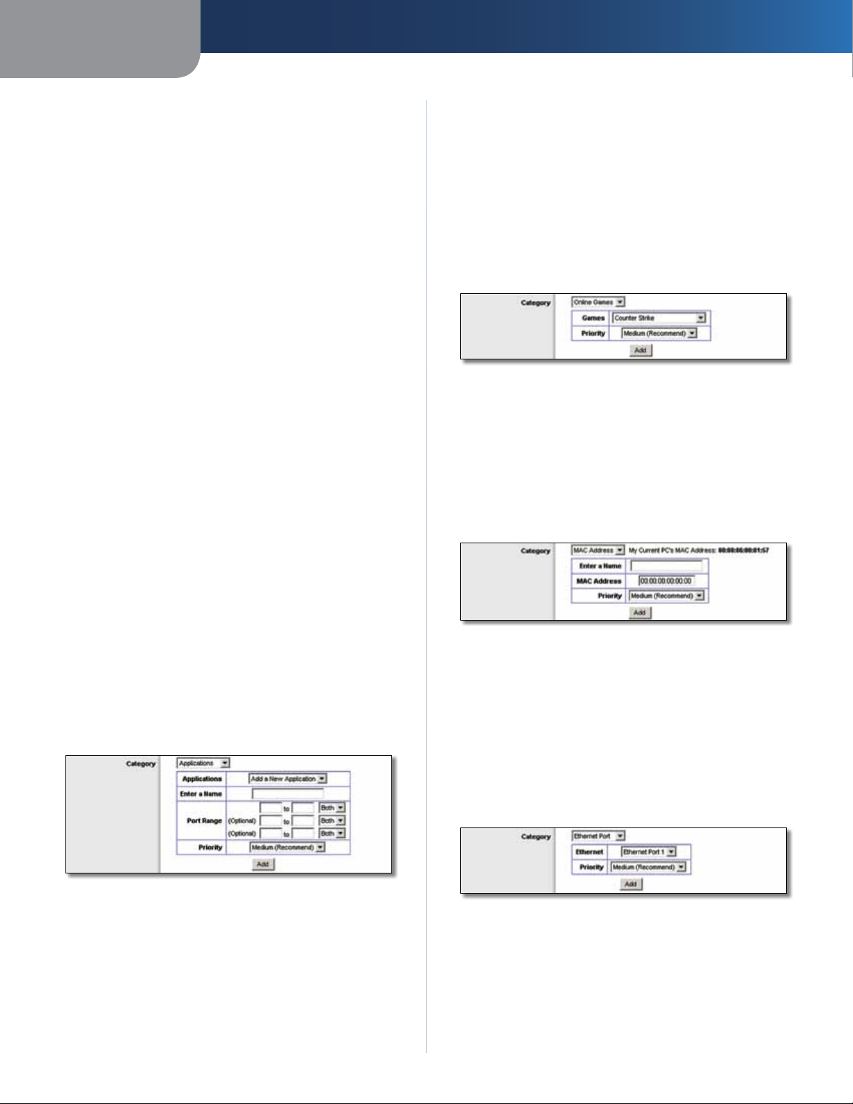
Online Games
QoS > Online Games
Games Select the appropriate game.
Priority Select the appropriate priority: High, Medium
(Recommend), Normal, or Low.
Click Add to save your changes. Your new entry will appear
in the Summary list.
MAC Address
Applications
Applications Select the appropriate application. If you
select Add a New Application, follow the Add a New
Application instructions.
Priority Select the appropriate priority: High, Medium,
Normal, or Low.
Click Add to save your changes. Your new entry will appear
in the Summary list.
Add a New Application
QoS > Add a New Application
Enter a Name Enter any name to indicate the name of
the entry.
Port Range Enter the port range that the application will
be using. For example, if you want to allocate bandwidth
for FTP, you can enter 21-21. If you need services for an
application that uses from 1000 to 1250, you enter 10001250 as your settings. You can have up to three ranges
to define for this bandwidth allocation. Port numbers
QoS > MAC Address
Enter a Name Enter a name for your device.
MAC Address Enter the MAC address of your device.
Priority Select the appropriate priority: High, Medium
(Recommend), Normal, or Low.
Click Add to save your changes. Your new entry will appear
in the Summary list.
Ethernet Port
QoS > Ethernet Port
Ethernet Select the appropriate Ethernet port.
Priority Select the appropriate priority: High, Medium
(Recommend), Normal, or Low.
Click Add to save your changes. Your new entry will appear
in the Summary list.
Wireless-N Broadband Router
23
Page 25
Chapter 3
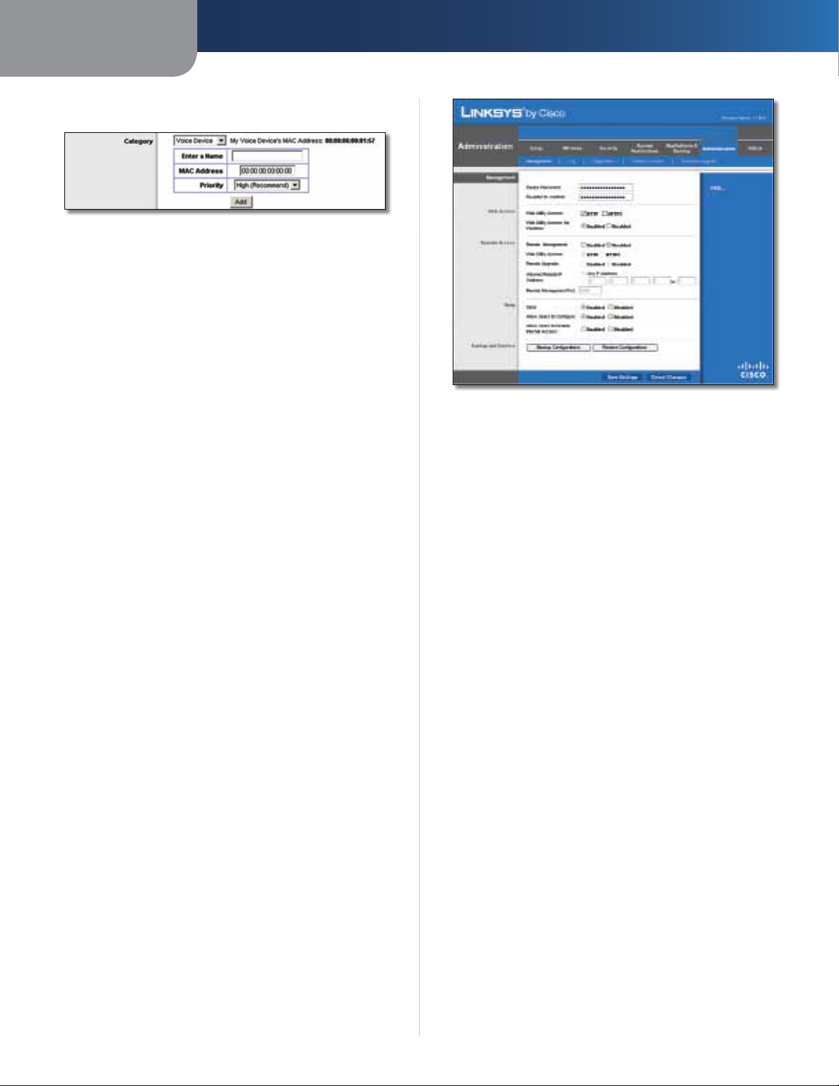
Voice Device
QoS > Voice Device
Enter a Name Enter a name for your voice device.
MAC Address Enter the MAC address of your voice
device.
Priority Select the appropriate priority: High
(Recommend), Medium, Normal, or Low.
Click Add to save your changes. Your new entry will appear
in the Summary list.
Summary
Advanced Configuration
Administration > Management
This lists the QoS entries you have created for your
applications and devices.
Priority This column displays the bandwidth priority of
High, Medium, Normal, or Low.
Name This column displays the application, device, or
port name.
Information This column displays the port range or
MAC address entered for your entry. If a pre-configured
application or game was selected, there will be no valid
entry shown in this section.
Remove Click this button to remove an entry.
Edit Click this button to make changes.
Click Save Settings to apply your changes, or click Cancel
Changes to cancel your changes.
Administration > Management
The Administration > Management screen allows the
network’s administrator to manage specific Router
functions for access and security.
Management
Router Access
To ensure the Router’s security, you will be asked for your
password when you access the Router’s web-based utility.
The default is admin.
Router Password Enter a new password for the Router.
Re-enter to confirm Enter the password again to
confirm.
Web Access
Web Utility Access HTTP (HyperText Transport Protocol)
is the communications protocol used to connect to servers
on the World Wide Web. HTTPS uses SSL (Secured Socket
Layer) to encrypt data transmitted for higher security.
Select HTTP or HTTPS. HTTP is the default.
Web Utility Access via Wireless If you are using the
Router in a public domain where you are giving wireless
access to your guests, you can disable wireless access to
the Router’s web-based utility. You will only be able to
access the utility via a wired connection if you disable
the setting. Keep the default, Enabled, to allow wireless
access to the utility, or select Disabled to block wireless
access to the utility.
Wireless-N Broadband Router
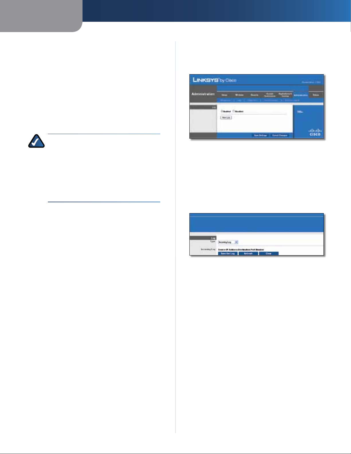
Remote Access
Remote Management To permit remote access of the
Router, from outside the local network, select Enabled.
Otherwise, keep the default, Disabled.
Web Utility Access HTTP (HyperText Transport Protocol)
is the communications protocol used to connect to servers
on the World Wide Web. HTTPS uses SSL (Secured Socket
Layer) to encrypt data transmitted for higher security.
Select HTTP or HTTPS. HTTP is the default.
24
Page 26
Chapter 3
Advanced Configuration
Remote Upgrade If you want to be able to upgrade the
Router remotely, from outside the local network, select
Enabled. (You must have the Remote Management
feature enabled as well.) Otherwise, keep the default,
Disabled.
Allowed Remote IP Address If you want to be able to
access the Router from any external IP address, select Any
IP Address. If you want to specify an external IP address or
range of IP addresses, then select the second option and
complete the fields provided.
Remote Management Port Enter the port number that
will be open to outside access.
NOTE: When you are in a remote location
and wish to manage the Router, enter
http://<Internet_IP_address>:port or
ht tp s:/ /<I nte rn et_ IP_ add re ss> :po rt ,
depending on whether you use HTTP or HTTPS.
Enter the Router’s specific Internet IP address in
place of <Internet_IP_address>, and enter the
Remote Management Port number in place of
the word port.
UPnP
Administration > Log
The Router can keep logs of all traffic for your Internet
connection.
Administration > Log
Log
Log To disable the Log function, select Disabled. To
monitor traffic between the network and the Internet,
keep the default, Enabled. With logging enabled, you can
choose to view temporary logs.
View Log To view the logs, click View Log.
Universal Plug and Play (UPnP) allows Windows Me and XP
to automatically configure the Router for various Internet
applications, such as gaming and videoconferencing.
UPnP If you want to use UPnP, keep the default setting,
Enabled. Otherwise, select Disabled.
Allow Users to Configure Keep the default, Enabled,
if you want to be able to make manual changes to the
Router while using the UPnP feature. Otherwise, select
Disabled.
Allow Users to Disable Internet Access Select Enabled,
if you want to be able to prohibit any and all Internet
connections. Otherwise, keep the default setting,
Disabled.
Backup and Restore
Backup Configurations To back up the Router’s
configuration settings, click this button and follow the onscreen instructions.
Restore Configurations To restore the Router’s
configuration settings, click this button and follow the onscreen instructions. (You must have previously backed up
the Router’s configuration settings.)
Click Save Settings to apply your changes, or click Cancel
Changes to cancel your changes.
Administration > Log > View Log
Log
• Type Select Incoming Log, Outgoing Log, Security
Log, or DHCP Client Log.
• <Type> Log The Incoming Log will display a
temporary log of the source IP addresses and
destination port numbers for the incoming Internet
traffic. The Outgoing Log will display a temporary
log of the local IP addresses, destination URLs/IP
addresses, and service/port numbers for the outgoing
Internet traffic. The Security log will display the login
information for the web-based utility. The DHCP
Client Log will display the LAN DHCP server status
information.
Click Save the Log to save this information to a file
on your PC’s hard drive. Click Refresh to update the
log. Click Clear to clear all the information that is
displayed.
Click Save Settings to apply your changes, or click Cancel
Changes to cancel your changes.
Wireless-N Broadband Router
25
Page 27
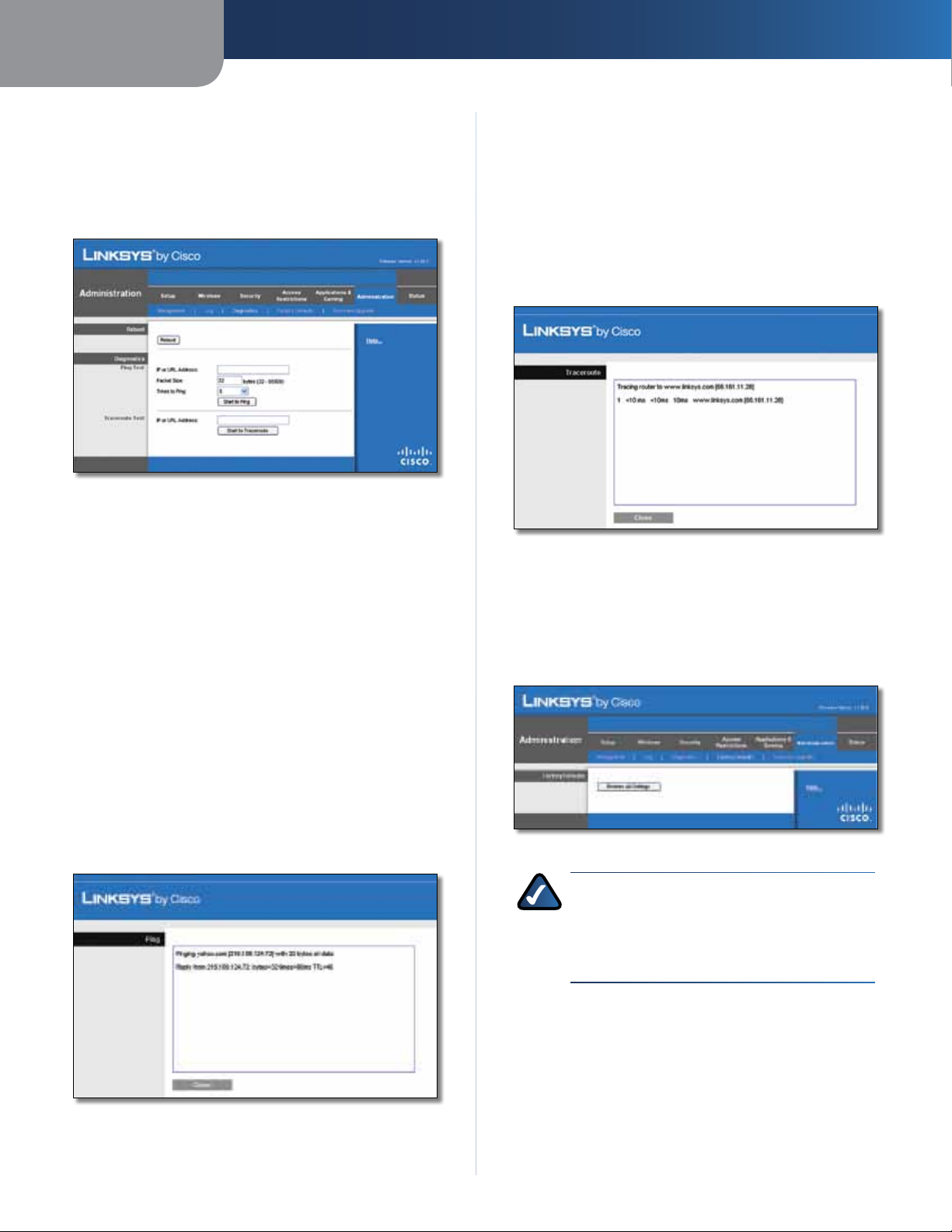
Chapter 3
Advanced Configuration
Administration > Diagnostics
The diagnostic tests (Ping and Traceroute) allow you to
check the connections of your network devices, including
connection to the Internet. This screen also allows you to
reset the router.
Administration > Diagnostics
Reboot
Reboot Click Reboot to reset the router.
Traceroute Test
The Traceroute test tests the performance of a
connection.
IP or URL Address Enter the address of the PC whose
connection you wish to test.
Start to Traceroute To run the test, click this button. The
Traceroute Test screen will show if the test was successful.
Click Close to return to the Diagnostics screen.
Diagnostics > Traceroute
Diagnostics
Ping Test
The Ping test checks the status of a connection.
IP or URL Address Enter the address of the PC whose
connection you wish to test.
Packet Size Enter the packet size you want to use. The
default is 32 bytes.
Times to Ping Enter many times you wish to test it.
Start to Ping To run the test, click this button. The Ping
Test screen will show if the test was successful. Click Close
to return to the Diagnostics screen.
Administration > Factory Defaults
The Administration > Factory Defaults screen allows you
to restore the Router’s configuration to its factory default
settings.
Administration > Factory Defaults
NOTE: Do not restore the factory defaults unless
you are having difficulties with the Router and
have exhausted all other troubleshooting
measures. Once the Router is reset, you will have
to re-enter all of your configuration settings.
Factory Defaults
Diagnostics > Ping
Wireless-N Broadband Router
Restore All Settings To reset the Router’s settings to the
default values, click this button and then follow the onscreen instructions. Any settings you have saved will be
lost when the default settings are restored.
26
Page 28
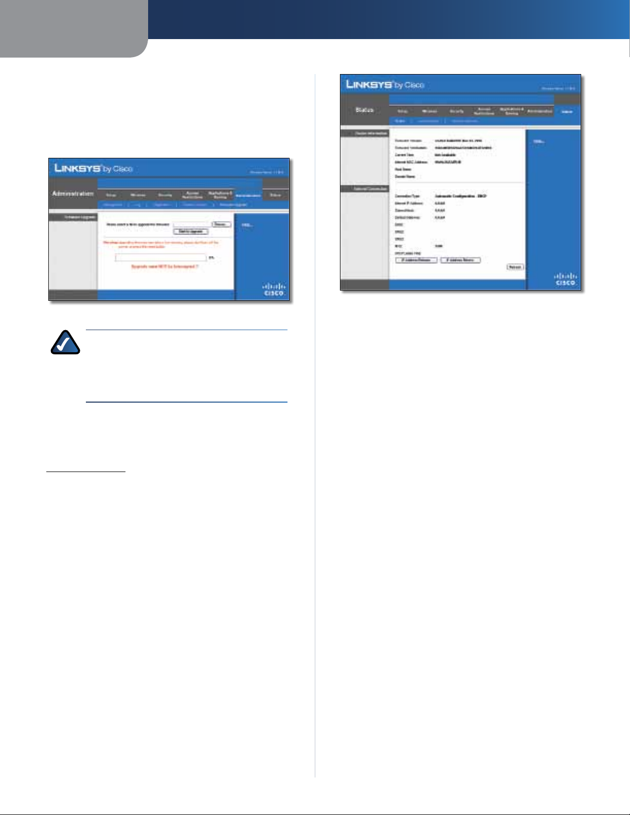
Chapter 3
Administration > Firmware Upgrade
The Firmware Upgrade screen allows you to upgrade the
Router’s firmware. Do not upgrade the firmware unless
you are experiencing problems with the Router or the new
firmware has a feature you want to use.
Administration > Firmware Upgrade
Advanced Configuration
Status > Router
NOTE: The Router may lose the settings you
have customized. Before you upgrade its
firmware, write down all of your custom settings.
After you upgrade its firmware, you will have to
re-enter all of your configuration settings.
Firmware Upgrade
Before upgrading the firmware, download the Router’s
firmware upgrade file from the Linksys website,
www.linksys.com. Then extract the file.
Please select a file to upgrade the firmware Click
Browse and select the extracted firmware upgrade file.
Start to Upgrade After you have selected the
appropriate file, click this button, and f
instructions.
ollow the on-screen
Status > Router
The Router screen displays information about the Router
and its current settings.
Router Information
Firmware Version This is the version number of the
Router’s current firmware.
Firmware Verification This shows the MD5 value
generated during code compilation.
Current Time This shows the time set on the Router.
Internet MAC Address This is the Router’s MAC Address,
as seen by your ISP.
Host Name If required by your ISP, this was entered on
the Basic Setup screen.
Domain Name If required by your ISP, this was entered
on the Basic Setup screen.
Internet Connection
This section shows the current network information
stored in the Router. The information varies depending on
the Internet connection type selected on the Basic Setup
screen.
Click Refresh to update the on-screen information.
Status > Local Network
Wireless-N Broadband Router
The Local Network screen displays information about the
local, wired network.
27
Page 29
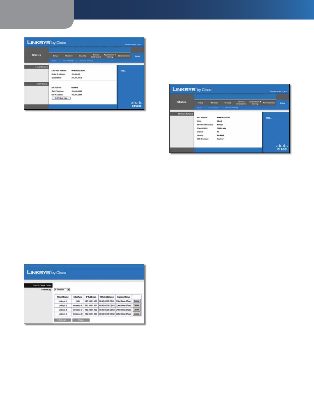
Chapter 3
Status > Local Network
Local Network
Local MAC Address The MAC address of the Router’s
local, wired interface is displayed here.
Advanced Configuration
date information, click Refresh. To exit this screen and
return to the Local Network screen, click Close.
Status > Wireless Network
The Wireless Network screen displays information about
your wireless network.
Router IP Address This shows the Router’s IP address, as
it appears on your local network.
Subnet Mask This shows the Subnet Mask of the Router.
DHCP Server
DHCP Server The status of the Router’s DHCP server
function is displayed here.
Start IP Address For the range of IP addresses used by
devices on your local network, the starting IP address is
shown here.
End IP Address For the range of IP addresses used by
devices on your local network, the ending IP address is
shown here.
DHCP Clients Table Click this button to view a list of PCs
that are using the Router as a DHCP server.
Status > Wireless
Wireless Network
MAC Address The MAC address of the Router’s local,
wireless interface is displayed here.
Mode Displayed here is the wireless mode used by the
network.
Network Name (SSID) Displayed here is the name of the
wireless network, which is also called the SSID.
Channel Width Shown here is the Radio Band setting
selected on the Basic Wireless Settings screen.
Channel Shown here is the Channel setting selected on
the Basic Wireless Settings screen.
Security Displayed here is the wireless security method
used by the Router.
SSID Broadcast Displayed here is the status of the SSID
Broadcast feature.
DHCP Clients Table
DHCP Client Table
The DHCP Client Table lists computers and other
devices that have been assigned IP addresses by the
Router. The list can be sorted by Client Name, Interface,
IP Address, MAC Address, and Expired Time (how
much time is left for the current IP address). To remove
a DHCP client, click Delete. To retrieve the most up-to-
Wireless-N Broadband Router
28
Page 30

Appendix A
Troubleshooting
Appendix A: Troubleshooting
Your computer cannot connect to the Internet.
Follow these instructions until your computer can connect
to the Internet:
• Make sure that the Router is powered on. The Power
LED should be green and not flashing.
• If the Power LED is flashing, then power off all of
your network devices, including the modem, Router,
and computers. Then power on each device in the
following order:
1. Cable or DSL modem
2. Router
3. Computer
• Check the cable connections. The computer should
be connected to one of the ports numbered 1-4 on
the Router, and the modem must be connected to the
Internet port on the Router.
The modem does not have an Ethernet port.
The modem is a dial-up modem for traditional dial-up
service. To use the Router, you need a cable/DSL modem
and high-speed Internet connection.
You cannot use the DSL service to connect manually to
the Internet.
After you have installed the Router, it will automatically
connect to your Internet Service Provider (ISP), so you no
longer need to connect manually.
When you double-click the web browser, you are
prompted for a username and password. If you want to
get rid of the prompt, follow these instructions.
Launch the web browser and perform the following steps
(these steps are specific to Internet Explorer but are similar
for other browsers):
1. Select Tools > Internet Options.
2. Click the Connections tab.
3. Select Never dial a connection.
4. Click OK.
The Router does not have a coaxial port for the cable
connection.
The Router does not replace your modem. You still need
your cable modem in order to use the Router. Connect
your cable connection to the cable modem, and then
insert the setup CD into your computer. Click Setup and
follow the on-screen instructions.
The computer cannot connect wirelessly to the network.
Make sure the wireless network name or SSID is the same
on both the computer and the Router. If you have enabled
wireless security, then make sure the same security
method and key are used by both the computer and the
Router.
You need to modify the settings on the Router.
Open the web browser (for example, Internet Explorer or
Firefox), and enter the Router’s IP address in the address
field (the default IP address is 192.168.1.1). When
prompted, enter the password to the Router (the default is
admin). Click the appropriate tab to change the settings.
The DSL telephone line does not t into the Router’s
Internet port.
The Router does not replace your modem. You still need
your DSL modem in order to use the Router. Connect the
telephone line to the DSL modem, and then insert the
setup CD into your computer. Click Setup and follow the
on-screen instructions.
Wireless-N Broadband Router
WEB: If your questions are not addressed here,
refer to the Linksys website, www.linksys.com
29
Page 31

Appendix B
Appendix B: Specifications
Model WRT160N
Standards Draft 802.11n, 802.11g, 802.11b,
802.3, 802.3u
Ports Power, Internet, and Ethernet (1-4)
Buttons Reset, Wi-Fi Protected Setup
LEDs Ethernet (1-4), Wi-Fi Protected
Setup, Wireless, Internet, Power
Cabling Type CAT 5e
RF Pwr (EIRP) in dBm 17 dBm
Antenna Gain in dBi 1.5 dBi
UPnP able/cert Able
Security Features WEP, WPA, WPA2
Security Key Bits 128-Bit,
Specifications
Environmental
Dimensions 7.95" x 6.3" x 1.34"
(202 x 160 x 34 mm)
Weight 10.4 oz (0.29 kg)
Power 12V, 0.5A
Certication FCC, CE, IC-03, Wi-Fi
Operating Temp. 0 to 40°C (32 to 104°F)
Storage Temp. -20 to 60°C (-4 to 140°F)
Operating Humidity 10 to 85% Noncondensing
Storage Humidity 5 to 90% Noncondensing
Wireless-N Broadband Router
30
Page 32

Appendix C
Warranty Information
Appendix C: Warranty Information
Limited Warranty
Linksys warrants that this Linksys hardware product will be
substantially free of defects in materials and workmanship
arising under normal use during the Warranty Period,
which begins on the date of purchase by the original enduser purchaser and lasts for the period specified below:
• Two (2) years for new product
• Ninety (90) days for refurbished product
This limited warranty is non-transferable and extends only
to the original end-user purchaser. Your exclusive remedy
and Linksys’ entire liability under this limited warranty
will be for Linksys, at its option, to (a) repair the product
with new or refurbished parts, (b) replace the product
with a reasonably available equivalent new or refurbished
Linksys product, or (c) refund the purchase price of the
product less any rebates. Any repaired or replacement
products will be warranted for the remainder of the
original Warranty Period or thirty (30) days, whichever is
longer. All products and/or parts that are replaced become
the property of Linksys.
This limited warranty shall apply in addition to any
statutory or other rights which you may have under a
contract of sale.
Exclusions and Limitations
This limited warranty does not apply if: (a) the product
assembly seal has been removed or damaged, (b) the
product has been altered or modified, except by Linksys,
(c) the product damage was caused by use with nonLinksys products, (d) the product has not been installed,
operated, repaired, or maintained in accordance with
instructions supplied by Linksys, (e) the product has
been subjected to abnormal physical or electrical stress,
misuse, negligence, or accident, (f ) the serial number on
the Product has been altered, defaced, or removed, or (g)
the product is supplied or licensed for beta, evaluation,
testing or demonstration purposes for which Linksys does
not charge a purchase price or license fee.
ALL SOFTWARE PROVIDED BY LINKSYS WITH THE PRODUCT,
WHETHER FACTORY LOADED ON THE PRODUCT OR
CONTAINED ON MEDIA ACCOMPANYING THE PRODUCT,
IS PROVIDED “AS IS” WITHOUT ANY WARRANTY OF ANY
KIND. Without limiting the foregoing, Linksys does not
warrant that the operation of the product or software will
be uninterrupted or error free. Also, due to the continual
development of new techniques for intruding upon and
attacking networks, Linksys does not warrant that the
product, service, software or any equipment, system or
network on which the product or software is used will be
free of vulnerability to intrusion or attack. The product
may include or be bundled with third party software or
service offerings. This limited warranty shall not apply to
such third party software or service offerings. This limited
warranty does not guarantee any continued availability
of a third party’s service for which this product’s use or
operation may require.
TO THE EXTENT NOT PROHIBITED BY LAW, ALL IMPLIED
WARRANTIES AND CONDITIONS OF MERCHANTABILITY,
SATISFACTORY QUALITY OR FITNESS FOR A PARTICULAR
PURPOSE ARE LIMITED TO THE DURATION OF THE
WARRANTY PERIOD. ALL OTHER EXPRESS OR IMPLIED
CONDITIONS, REPRESENTATIONS AND WARRANTIES,
INCLUDING, BUT NOT LIMITED TO, ANY IMPLIED
WARRANTY OF NON-INFRINGEMENT, ARE DISCLAIMED.
Some jurisdictions do not allow limitations on how long
an implied warranty lasts, so the above limitation may not
apply to you. This limited warranty gives you specific legal
rights, and you may also have other rights which vary by
jurisdiction.
TO THE EXTENT NOT PROHIBITED BY LAW, IN NO EVENT
WILL LINKSYS BE LIABLE FOR ANY LOST DATA, REVENUE
OR PROFIT, OR FOR SPECIAL, INDIRECT, CONSEQUENTIAL,
INCIDENTAL OR PUNITIVE DAMAGES, REGARDLESS OF THE
THEORY OF LIABILITY (INCLUDING NEGLIGENCE), ARISING
OUT OF OR RELATED TO THE USE OF OR INABILITY TO
USE THE PRODUCT (INCLUDING ANY SOFTWARE), EVEN
IF LINKSYS HAS BEEN ADVISED OF THE POSSIBILITY OF
SUCH DAMAGES. IN NO EVENT WILL LINKSYS’ LIABILITY
EXCEED THE AMOUNT PAID BY YOU FOR THE PRODUCT.
The foregoing limitations will apply even if any warranty
or remedy provided under this limited warranty fails of
its essential purpose. Some jurisdictions do not allow
the exclusion or limitation of incidental or consequential
damages, so the above limitation or exclusion may not
apply to you.
Obtaining Warranty Service
If you have a question about your product or experience a
problem with it, please go to www.linksys.com/support
where you will find a variety of online support tools and
information to assist you with your product. If the product
proves defective during the Warranty Period, contact
Linksys Technical Support for instructions on how to
obtain warranty service. The telephone number for Linksys
Technical Support in your area can be found in the product
User Guide and at www.linksys.com. Have your product
serial number and proof of purchase on hand when calling.
A DATED PROOF OF ORIGINAL PURCHASE IS REQUIRED
TO PROCESS WARRANTY CLAIMS. If you are requested to
return your product, you will be given a Return Materials
Authorization (RMA) number. You are responsible for
properly packaging and shipping your product to Linksys
at your cost and risk. You must include the RMA number
Wireless-N Broadband Router
31
Page 33

Appendix C
and a copy of your dated proof of original purchase when
returning your product. Products received without a RMA
number and dated proof of original purchase will be
rejected. Do not include any other items with the product
you are returning to Linksys. Defective product covered
by this limited warranty will be repaired or replaced and
returned to you without charge. Customers outside of
the United States of America and Canada are responsible
for all shipping and handling charges, custom duties,
VAT and other associated taxes and charges. Repairs or
replacements not covered under this limited warranty will
be subject to charge at Linksys’ then-current rates.
Technical Support
This limited warranty is neither a service nor a
support contract. Information about Linksys’ current
technical support offerings and policies (including
any fees for support services) can be found at
www.linksys.com/support
Warranty Information
General
This limited warranty is governed by the laws of the
jurisdiction in which the Product was purchased by you.
If any portion of this limited warranty is found to be void
or unenforceable, its remaining provisions shall remain in
full force and effect.
Please direct all inquiries to: Linksys, P.O. Box 18558, Irvine,
CA 92623.
For more information, please contact us
www.linksys.com
Select your country, and then select SUPPORT/
TECHNICAL
For product returns:
Select your Country and then select CUSTOMER SUPPORT
Wireless-N Broadband Router
32
Page 34

Appendix D
Regulatory Information
Appendix D: Regulatory Information
FCC Statement
This device complies with Part 15 of the FCC Rules.
Operation is subject to the following two conditions: (1)
This device may not cause harmful interference, and (2) this
device must accept any interference received, including
interference that may cause undesired operation.
This product has been tested and complies with the
specifications for a Class B digital device, pursuant to Part
15 of the FCC Rules. These limits are designed to provide
reasonable protection against harmful interference in
a residential installation. This equipment generates,
uses, and can radiate radio frequency energy and, if not
installed and used according to the instructions, may
cause harmful interference to radio communications.
However, there is no guarantee that interference will not
occur in a particular installation. If this equipment does
cause harmful interference to radio or television reception,
which is found by turning the equipment off and on, the
user is encouraged to try to correct the interference by
one or more of the following measures:
Safety Notices
WARNING: Do not use this product near water,
for example, in a wet basement or near a
swimming pool.
WARNING: Avoid using this product during an
electrical storm. There may be a remote risk of
electric shock from lightning.
• Reorient or relocate the receiving antenna
• Increase the separation between the equipment or
devices
• Connect the equipment to an outlet other than the
receiver’s
• Consult a dealer or an experienced radio/TV technician
for assistance
FCC Caution: Any changes or modifications not expressly
approved by the party responsible for compliance could
void the user’s authority to operate this equipment.
FCC Radiation Exposure Statement
This equipment complies with FCC radiation exposure limits
set forth for an uncontrolled environment. This equipment
should be installed and operated with minimum distance
20 cm between the radiator and your body.
Wireless-N Broadband Router
33
Page 35

Appendix D
Regulatory Information
Industry Canada Statement
This Class B digital apparatus complies with Canadian
ICES-003 and RSS210.
Operation is subject to the following two conditions:
1. This device may not cause interference and
2. This device must accept any interference, including
interference that may cause undesired operation of
the device.
Industry Canada Radiation Exposure Statement
This equipment complies with IC radiation exposure limits
set forth for an uncontrolled environment. This equipment
should be installed and operated with minimum distance
20 cm between the radiator & your body.
This transmitter must not be co-located or operating in
conjunction with any other antenna or transmitter.
Avis d’Industrie Canada
Cet appareil numérique de la classe B est conforme aux
normes NMB-003 et RSS210 du Canada.
L’utilisation de ce dispositif est autorisée seulement aux
conditions suivantes :
1. il ne doit pas produire de brouillage et
2. il doit accepter tout brouillage radioélectrique reçu,
même si ce brouillage est susceptible de compromettre
le fonctionnement du dispositif.
Wireless Disclaimer
The maximum performance for wireless is derived from
IEEE Standard 802.11 specifications. Actual performance
can vary, including lower wireless network capacity,
data throughput rate, range and coverage. Performance
depends on many factors, conditions and variables,
including distance from the access point, volume of
network traffic, building materials and construction,
operating system used, mix of wireless products used,
interference and other adverse conditions.
Avis de non-responsabilité concernant les appareils sans fil
Les performances maximales pour les réseaux sans fil
sont tirées des spécifications de la norme IEEE 802.11.
Les performances réelles peuvent varier, notamment
en fonction de la capacité du réseau sans fil, du débit
de la transmission de données, de la portée et de la
couverture. Les performances dépendent de facteurs,
conditions et variables multiples, en particulier de la
distance par rapport au point d’accès, du volume du trafic
réseau, des matériaux utilisés dans le bâtiment et du
type de construction, du système d’exploitation et de la
combinaison de produits sans fil utilisés, des interférences
et de toute autre condition défavorable.
Avis d’Industrie Canada concernant l’exposition
aux radiofréquences
Ce matériel est conforme aux limites établies par IC
en matière d’exposition aux radiofréquences dans un
environnement non contrôlé. Ce matériel doit être installé
et utilisé à une distance d’au moins 20 cm entre l’antenne
et le corps de l’utilisateur.
L’émetteur ne doit pas être placé près d’une autre antenne
ou d’un autre émetteur, ou fonctionner avec une autre
antenne ou un autre émetteur.
Wireless-N Broadband Router
34
Page 36

Appendix D
Regulatory Information
Declaration of Conformity with Regard to EU Directive 1999/5/EC (R&TTE Directive)
Compliance Information for 2.4-GHz and 5-GHz Wireless
Products Relevant to the EU and Other Countries Following
the EU Directive 1999/5/EC (R&TTE Directive)
Бъ л га р ск и
[Bulgarian]
Česky
[Czech]:
Dansk
[Danish]:
Deutsch
[German]:
Eesti
[Estonian]:
Това оборудване отговаря на съществените
изисквания и приложими клаузи на
Директива 1999/5/ЕС.
Toto zařízení je v souladu se základními
požadavky a ostatními odpovídajícími
ustanoveními Směrnice 1999/5/EC.
Dette udstyr er i overensstemmelse med
de væsentlige krav og andre relevante
bestemmelser i Direktiv 1999/5/EF.
Dieses Gerät entspricht den grundlegenden
Anforderungen und den weiteren
entsprechenden Vorgaben der Richtlinie
1999/5/EU.
See seade vastab direktiivi 1999/5/EÜ olulistele
nõuetele ja teistele asjakohastele sätetele.
Nederlands
[Dutch]:
Malti
[Maltese]:
Magyar
[Hungarian]:
Norsk
[Norwegian]:
Polski
[Polish]:
Português
[Portuguese]:
Română
[Romanian]
Dit apparaat voldoet aan de essentiele eisen
en andere van toepassing zijnde bepalingen
van de Richtlijn 1999/5/EC.
Dan l-apparat huwa konformi mal-ħtiġiet
essenzjali u l-provedimenti l-oħra rilevanti
tad-Direttiva 1999/5/EC.
Ez a készülék teljesíti az alapvető
követelményeket és más 1999/5/EK
irányelvben meghatározott vonatkozó
rendelkezéseket.
Dette utstyret er i samsvar med de
grunnleggende krav og andre relevante
bestemmelser i EU-direktiv 1999/5/EF.
Urządzenie jest zgodne z ogólnymi
wymaganiami oraz szczególnymi warunkami
określonymi Dyrektywą UE: 1999/5/EC.
Este equipamento está em conformidade com
os requisitos essenciais e outras provisões
relevantes da Directiva 1999/5/EC.
Acest echipament este in conformitate
cu cerintele esentiale si cu alte prevederi
relevante ale Directivei 1999/5/EC.
English:
Español
[Spanish]:
Ελληνική
[Greek]:
Français
[French]:
Íslenska
[Icelandic]:
Italiano
[Italian]:
Latviski
[Latvian]:
Lietuvių
[Lithuanian]:
This equipment is in compliance with the
essential requirements and other relevant
provisions of Directive 1999/5/EC.
Este equipo cumple con los requisitos
esenciales asi como con otras disposiciones
de la Directiva 1999/5/CE.
Αυτός ο εξοπλισµός είναι σε συµµόρφωση µε
τις ουσιώδεις απαιτήσεις και άλλες σχετικές
διατάξεις της Οδηγίας 1999/5/EC.
Cet appareil est conforme aux exigences
essentielles et aux autres dispositions
pertinentes de la Directive 1999/5/EC.
Þetta tæki er samkvæmt grunnkröfum og
öðrum viðeigandi ákvæðum Tilskipunar
1999/5/EC.
Questo apparato é conforme ai requisiti
essenziali ed agli altri principi sanciti dalla
Direttiva 1999/5/CE.
Šī iekārta atbilst Direktīvas 1999/5/
EK būtiskajām prasībām un citiem ar to
saistītajiem noteikumiem.
Šis įrenginys tenkina 1999/5/EB Direktyvos
esminius reikalavimus ir kitas šios direktyvos
nuostatas.
Slovensko
[Slovenian]:
Slovensky
[Slovak]:
Suomi
[Finnish]:
Svenska
[Swedish]:
Ta naprava je skladna z bistvenimi zahtevami
in ostalimi relevantnimi pogoji Direktive
1999/5/EC.
Toto zariadenie je v zhode so základnými
požiadavkami a inými príslušnými nariadeniami
direktív: 1999/5/EC.
Tämä laite täyttää direktiivin 1999/5/EY
olennaiset vaatimukset ja on siinä asetettujen
muiden laitetta koskevien määräysten
mukainen.
Denna utrustning är i överensstämmelse med
de väsentliga kraven och andra relevanta
bestämmelser i Direktiv 1999/5/EC.
For all products, the Declaration of Conformity (DofC) is
available through one or more of these options:
• A pdf file is included on the product’s CD.
• A print copy is included with the product.
• A pdf file is available on the product’s webpage.
Visit www.linksysbycisco.com/international and
select your country or region. Then select your
product.
If you need any other technical documentation, see the
“Technical Documents on www.linksysbycisco.com/
international” section, as shown later in this appendix.
Wireless-N Broadband Router
35
Page 37

Appendix D
XXXX
Regulatory Information
Wireless Equipment (Wireless-N/G/A/B Products)
The following standards were applied during the
assessment of the product against the requirements of
the Directive 1999/5/EC:
• Radio: EN 300 328 and/or EN 301 893 as applicable
• EMC: EN 301 489-1, EN 301 489-17
• Safety: EN 60950 and either EN 50385 or EN 50371
Dynamic Frequency Selection (DFS) and Transmit Power
Control (TPC) are required for operation in the 5 GHz
band.
DFS: The equipment meets the DFS requirements as
defined in ETSI EN 301 893. This feature is required by
the regulations to avoid interference with Radio Location
Services (radars).
TPC: For operation in the 5 GHz band, the maximum power
level is 3 dB or more below the applicable limit. As such,
TPC is not required.
CE Marking
For the Linksys Wireless-N, -G, -B and/or -A products,
the following CE mark, notified body number (where
applicable) and class 2 identifier are added to the
equipment.
In the majority of the EU and other European countries,
the 2.4- and 5-GHz bands have been made available
for the use of wireless local area networks (LANs). The
table labelled “Overview of Regulatory Requirements for
Wireless LANs” provides an overview of the regulatory
requirements applicable for the 2.4- and 5-GHz bands.
Later in this document you will find an overview of
countries in which additional restrictions or requirements
or both are applicable.
The requirements for any country may evolve. Linksys
recommends that you check with the local authorities for
the latest status of their national regulations for both the
2.4- and 5-GHz wireless LANs.
Overview of Regulatory Requirements for Wireless LANs
Frequency
Band (MHz)
2400-2483,5 100 X
5150-5250 200 X
5250-5350
5470-5725
†Dynamic Frequency Selection and Transmit Power Control are required
in the frequency ranges of 5250-5350 MHz and 5470-5725 MHz.
The following countries have restrictions and/or
requirements in addition to those given in the table
labelled “Overview of Regulatory Requirements for
Wireless LANs”:
Max Power Level
†
†
Indoor
(EIRP) (mW)
200 X
1000 X
ONLY
Indoor &
Outdoor
or
Check the CE label on the product to find out which
notified body was involved during the assessment.
National Restrictions
This product may be used in all EU countries (and other
countries following the EU directive 1999/5/EC) without
any limitation except for the countries mentioned below:
Ce produit peut être utilisé dans tous les pays de l’UE (et dans
tous les pays ayant transposés la directive 1999/5/CE) sans
aucune limitation, excepté pour les pays mentionnés cidessous:
Questo prodotto è utilizzabile in tutte i paesi EU (ed in tutti
gli altri paesi che seguono le direttive EU 1999/5/EC) senza
nessuna limitazione, eccetto per i paesi menzionati di
seguito:
Das Produkt kann in allen EU Staaten ohne Einschränkungen
eingesetzt werden (sowie in anderen Staaten die der EU
Direktive 1999/5/CE folgen) mit Außnahme der folgenden
aufgeführten Staaten:
Wireless-N Broadband Router
Croatia
License is required in the band 5150-5350 MHz.
Za pojas od 5150-5350 MHz potrebna je licenca.
Denmark
In Denmark, the band 5150 - 5350 MHz is also allowed for
outdoor usage.
I Danmark må frekvensbåndet 5150 - 5350 også anvendes
udendørs.
France
For 2,4 GHz, the product is allowed to be used outdoors
in the band 2454 - 2483,5 MHz with the condition of
eirp limited to 10mW (10 dBm). When operating in the
band 2400-2454 MHz, it is restricted for indoor and
outdoor use with eirp limited to 100mW (20 dBm). Check
http://www.arcep.fr/ for more details.
Pour la bande 2,4 GHz, l’équipement peut être utilisé en
extérieur dans la bande 2 454 – 2 483,5 MHz, seulement si
la puissance PIRE ne dépasse pas 10 mW (10 dBm). Lors
du fonctionnement dans la bande 2 400 – 2 454 MHz,
l’utilisation est limitée en intérieur et en extérieur avec une
36
Page 38

Appendix D
Regulatory Information
puissance PIRE de à 100 mW (20 dBm) maximum. Consultez
http://www.arcep.fr/ pour de plus amples détails.
Applicable Power Levels in France
Frequency
Band (MHz)
2400-2454 100 (20 dBm) X X
2454-2483,5 100 (20 dBm) X
2454-2483,5 10 (10 dBm) X
Power Level
(EIRP), (mW)
Indoor Outdoor
Italy
This product meets the National Radio Interface and
the requirements specified in the National Frequency
Allocation Table for Italy. Unless this 2,4-GHz wireless
LAN product is operating within the boundaries of the
owner’s property, its use requires a “general authorization”.
Bands 5150-5350 MHz and 5470-5725 MHz require
general authorization if used outdoors. Please check
http://www.comunicazioni.it/it/ for more details.
Questo prodotto è conforme alla specifiche di Interfaccia
Radio Nazionali e rispetta il Piano Nazionale di ripartizione
delle frequenze in Italia. Se non viene installato all’interno
del proprio fondo, l’utilizzo di prodotti Wireless LAN a 2,4
GHz richiede una “Autorizzazione Generale”. L’utilizzo
all’aperto delle bande di frequenza 5150-5350 MHz e 54705725 MHz è soggetto ad autorizzazione generale. Consultare
http://www.comunicazioni.it/it/ per maggiori dettagli.
Latvia
The outdoor usage of the 2,4 GHz band requires an
authorization from the Electronic Communications Office.
Please check http://www.esd.lv for more details.
2,4 GHz frekveču joslas izmantošanai ārpus telpām
nepieciešama atļauja no Elektronisko sakaru direkcijas.
Vairāk informācijas: http://www.esd.lv.
Notes:
1. Although Norway, Switzerland and Liechtenstein are
not EU member states, the EU Directive 1999/5/EC has
also been implemented in those countries.
2. The regulatory limits for maximum output power are
specified in EIRP. The EIRP level of a device can be
calculated by adding the gain of the antenna used
(specified in dBi) to the output power available at the
connector (specified in dBm).
2.4 GHz Restrictions
This product is designed for use with the standard, integral
or dedicated (external) antenna(s) that is/are shipped
together with the equipment. However, some applications
may require the antenna(s), if removable, to be separated
from the product and installed remotely from the device
by using extension cables. For these applications, Linksys
offers an R-SMA extension cable (AC9SMA) and an R-TNC
extension cable (AC9TNC). Both of these cables are 9
metres long and have a cable loss (attenuation) of 5 dB. To
compensate for the attenuation, Linksys also offers higher
gain antennas, the HGA7S (with R-SMA connector) and
HGA7T (with R-TNC connector). These antennas have a
gain of 7 dBi and may only be used with either the R-SMA
or R-TNC extension cable.
Combinations of extension cables and antennas resulting
in a radiated power level exceeding 100 mW EIRP are
illegal.
Third-Party Software or Firmware
The use of software or firmware not supported/provided
by Linksys may result in the equipment no longer being
compliant with the regulatory requirements.
Technical Documents on www.linksysbycisco.com/international
Follow these steps to access technical documents:
1. Enter http://www.linksysbycisco.com/international
in your web browser.
2. Select the country or region in which you live.
3. Click the Products tab.
4. Select the appropriate product category.
5. Select the product sub-category, if necessary.
6. Select the product.
7. Select the type of documentation you want from the
More Information section. The document will open
in PDF format if you have Adobe Acrobat installed on
your computer.
NOTE: If you have questions regarding
the compliance of this product or you
cannot find the information you need,
please contact your local sales office or visit
www.linksysbycisco.com/international
Product Usage Restrictions
This product is designed for indoor usage only. Outdoor
usage is not recommended, unless otherwise noted.
Wireless-N Broadband Router
37
Page 39

Appendix D
Regulatory Information
User Information for Consumer Products Covered by EU Directive 2002/96/EC on Waste Electric and Electronic Equipment (WEEE)
This document contains important information for users
with regards to the proper disposal and recycling of
Linksys products. Consumers are required to comply with
this notice for all electronic products bearing the following
symbol:
English - Environmental Information for Customers in
the European Union
European Directive 2002/96/EC requires that the equipment
bearing this symbol on the product and/or its packaging must
not be disposed of with unsorted municipal waste. The symbol
indicates that this product should be disposed of separately
from regular household waste streams. It is your responsibility to
dispose of this and other electric and electronic equipment via
designated collection facilities appointed by the government or
local authorities. Correct disposal and recycling will help prevent
potential negative consequences to the environment and
human health. For more detailed information about the disposal
of your old equipment, please contact your local authorities,
waste disposal service, or the shop where you purchased the
product.
Български (Bulgarian) - Информация относно
опазването на околната среда за потребители в
Европейския съюз
Европейска директива 2002/96/EC изисква уредите, носещи
този символ върху изделието и/или опаковката му, да не
се изхвърля т с несортирани битови отпадъци. Символът
обозначава, че изделието трябва да се изхвърля отделно от
сметосъбирането на обикновените битови отпадъци. Ваша
е отговорността този и другите електрически и електронни
уреди да се изхвърлят в предварително определени от
държавните или общински органи специализирани пунктове
за събиране. Правилното изхвърляне и рециклиране
ще спомогнат да се предотвратят евентуални вредни за
околната среда и здравето на населението последствия. За
по-подробна информация относно изхвърлянето на вашите
стари уреди се обърнете към местните власти, службите за
сметосъбиране или магазина, от който сте закупили уреда.
Čeština (Czech) - Informace o ochraně životního
prostředí pro zákazníky v zemích Evropské unie
Evropská směrnice 2002/96/ES zakazuje, aby zařízení označené
tímto symbolem na produktu anebo na obalu bylo likvidováno
s netříděným komunálním odpadem. Tento symbol udává,
že daný produkt musí být likvidován odděleně od běžného
komunálního odpadu. Odpovídáte za likvidaci tohoto produktu
a dalších elektrických a elektronických zařízení prostřednictvím
určených sběrných míst stanovených vládou nebo místními
úřady. Správná likvidace a recyklace pomáhá předcházet
potenciálním negativním dopadům na životní prostředí a lidské
zdraví. Podrobnější informace o likvidaci starého vybavení si
laskavě vyžádejte od místních úřadů, podniku zabývajícího se
likvidací komunálních odpadů nebo obchodu, kde jste produkt
zakoupili.
Dansk (Danish) - Miljøinformation for kunder i EU
EU-direktiv 2002/96/EF kræver, at udstyr der bærer dette symbol
på produktet og/eller emballagen ikke må bortskaffes som
usorteret kommunalt affald. Symbolet betyder, at dette produkt
skal bortskaffes adskilt fra det almindelige husholdningsaffald.
Det er dit ansvar at bortskaffe dette og andet elektrisk og
elektronisk udstyr via bestemte indsamlingssteder udpeget
af staten eller de lokale myndigheder. Korrekt bortskaffelse
og genvinding vil hjælpe med til at undgå mulige skader for
miljøet og menneskers sundhed. Kontakt venligst de lokale
myndigheder, renovationstjenesten eller den butik, hvor du
har købt produktet, angående mere detaljeret information om
bortskaffelse af dit gamle udstyr.
Deutsch (German) - Umweltinformation für Kunden
innerhalb der Europäischen Union
Die Europäische Richtlinie 2002/96/EC verlangt, dass technische
Ausrüstung, die direkt am Gerät und/oder an der Verpackung mit
diesem Symbol versehen ist , nicht zusammen mit unsortiertem
Gemeindeabfall entsorgt werden darf. Das Symbol weist darauf
hin, dass das Produkt von regulärem Haushaltmüll getrennt
entsorgt werden sollte. Es liegt in Ihrer Verantwortung, dieses
Gerät und andere elektrische und elektronische Geräte über
die dafür zuständigen und von der Regierung oder örtlichen
Behörden dazu bestimmten Sammelstellen zu entsorgen.
Ordnungsgemäßes Entsorgen und Recyceln trägt dazu bei,
potentielle negative Folgen für Umwelt und die menschliche
Gesundheit zu vermeiden. Wenn Sie weitere Informationen zur
Entsorgung Ihrer Altgeräte benötigen, wenden Sie sich bitte an
die örtlichen Behörden oder städtischen Entsorgungsdienste
oder an den Händler, bei dem Sie das Produkt erworben haben.
Wireless-N Broadband Router
38
Page 40

Appendix D
Regulatory Information
Eesti (Estonian) - Keskkonnaalane informatsioon
Euroopa Liidus asuvatele klientidele
Euroopa Liidu direktiivi 2002/96/EÜ nõuete kohaselt on
seadmeid, millel on tootel või pakendil käesolev sümbol ,
keelatud kõrvaldada koos sorteerimata olmejäätmetega. See
sümbol näitab, et toode tuleks kõrvaldada eraldi tavalistest
olmejäätmevoogudest. Olete kohustatud kõrvaldama käesoleva
ja ka muud elektri- ja elektroonikaseadmed riigi või kohalike
ametiasutuste poolt ette nähtud kogumispunktide kaudu.
Seadmete korrektne kõrvaldamine ja ringlussevõtt aitab vältida
võimalikke negatiivseid tagajärgi keskkonnale ning inimeste
tervisele. Vanade seadmete kõrvaldamise kohta täpsema
informatsiooni saamiseks võtke palun ühendust kohalike
ametiasutustega, jäätmekäitlusfirmaga või kauplusega, kust te
toote ostsite.
Español (Spanish) - Información medioambiental para
clientes de la Unión Europea
La Directiva 2002/96/CE de la UE exige que los equipos que
lleven este símbolo en el propio aparato y/o en su embalaje
no deben eliminarse junto con otros residuos urbanos no
seleccionados. El símbolo indica que el producto en cuestión
debe separarse de los residuos domésticos convencionales con
vistas a su eliminación. Es responsabilidad suya desechar este y
cualesquiera otros aparatos eléctricos y electrónicos a través de
los puntos de recogida que ponen a su disposición el gobierno y
las autoridades locales. Al desechar y reciclar correctamente estos
aparatos estará contribuyendo a evitar posibles consecuencias
negativas para el medio ambiente y la salud de las personas. Si
desea obtener información más detallada sobre la eliminación
segura de su aparato usado, consulte a las autoridades locales,
al servicio de recogida y eliminación de residuos de su zona o
pregunte en la tienda donde adquirió el producto.
Ελληνικά (Greek) - Στοιχεία περιβαλλοντικής
προστασίας για πελάτες εντός της Ευρωπαϊκής
Ένωσης
Σύμφωνα με την Κοινοτική Οδηγία 2002/96/EC, ο εξοπλισμός
που φέρει αυτό το σύμβολο στο προϊόν ή/και τη συσκευασία
του δεν πρέπει να απορρίπτεται μαζί με τα μη διαχωρισμένα
αστικά απορρίμματα. Το σύμβολο υποδεικνύει ότι αυτό το προϊόν
θα πρέπει να απορρίπτεται ξεχωριστά από τα συνήθη οικιακά
απορρίμματα. Είστε υπεύθυνος για την απόρριψη του παρόντος
και άλλου ηλεκτρικού και ηλεκτρονικού εξοπλισμού μέσω των
καθορισμένων εγκαταστάσεων συγκέντρωσης απορριμμάτων,
οι οποίες ορίζονται από το κράτος ή τις αρμόδιες τοπικές αρχές.
Η σωστή απόρριψη και ανακύκλωση συμβάλλει στην πρόληψη
ενδεχόμενων αρνητικών επιπτώσεων στο περιβάλλον και την
υγεία. Για περισσότερες πληροφορίες σχετικά με την απόρριψη
του παλαιού σας εξοπλισμού, επικοινωνήστε με τις τοπικές αρχές,
τις υπηρεσίες αποκομιδής απορριμμάτων ή το κατάστημα από
το οποίο αγοράσατε το προϊόν.
Français (French) - Informations environnementales
pour les clients de l’Union européenne
La directive européenne 2002/96/CE exige que l’équipement
sur lequel est apposé ce symbole sur le produit et/ou son
emballage ne soit pas jeté avec les autres ordures ménagères. Ce
symbole indique que le produit doit être éliminé dans un circuit
distinct de celui pour les déchets des ménages. Il est de votre
responsabilité de jeter ce matériel ainsi que tout autre matériel
électrique ou électronique par les moyens de collecte indiqués
par le gouvernement et les pouvoirs publics des collectivités
territoriales. L’élimination et le recyclage en bonne et due forme
ont pour but de lutter contre l’impact néfaste potentiel de ce
type de produits sur l’environnement et la santé publique. Pour
plus d’informations sur le mode d’élimination de votre ancien
équipement, veuillez prendre contact avec les pouvoirs publics
locaux, le service de traitement des déchets, ou l’endroit où vous
avez acheté le produit.
Italiano (Italian) - Informazioni relative all’ambiente
per i clienti residenti nell’Unione Europea
La direttiva europea 2002/96/EC richiede che le apparecchiature
contrassegnate con questo simbolo sul prodotto e/o
sull’imballaggio non siano smaltite insieme ai rifiuti urbani
non differenziati. Il simbolo indica che questo prodotto non
deve essere smaltito insieme ai normali rifiuti domestici. È
responsabilità del proprietario smaltire sia questi prodotti sia
le altre apparecchiature elettriche ed elettroniche mediante
le specifiche strutture di raccolta indicate dal governo o dagli
enti pubblici locali. Il corretto smaltimento ed il riciclaggio
aiuteranno a prevenire conseguenze potenzialmente negative
per l’ambiente e per la salute dell’essere umano. Per ricevere
informazioni più dettagliate circa lo smaltimento delle vecchie
apparecchiature in Vostro possesso, Vi invitiamo a contattare gli
enti pubblici di competenza, il servizio di smaltimento rifiuti o il
negozio nel quale avete acquistato il prodotto.
Latviešu valoda (Latvian) - Ekoloģiska informācija
klientiem Eiropas Savienības jurisdikcijā
Direktīvā 2002/96/EK ir prasība, ka aprīkojumu, kam pievienota
zīme uz paša izstrādājuma vai uz tā iesaiņojuma, nedrīkst
izmest nešķirotā veidā kopā ar komunālajiem atkritumiem
(tiem, ko rada vietēji iedzīvotāji un uzņēmumi). Šī zīme nozīmē
to, ka šī ierīce ir jāizmet atkritumos tā, lai tā nenonāktu kopā ar
parastiem mājsaimniecības atkritumiem. Jūsu pienākums ir šo
un citas elektriskas un elektroniskas ierīces izmest atkritumos,
izmantojot īpašus atkritumu savākšanas veidus un līdzekļus, ko
nodrošina valsts un pašvaldību iestādes. Ja izmešana atkritumos
un pārstrāde tiek veikta pareizi, tad mazinās iespējamais
kaitējums dabai un cilvēku veselībai. Sīkākas ziņas par
novecojuša aprīkojuma izmešanu atkritumos jūs varat saņemt
vietējā pašvaldībā, atkritumu savākšanas dienestā, kā arī veikalā,
kur iegādājāties šo izstrādājumu.
Wireless-N Broadband Router
39
Page 41

Appendix D
Regulatory Information
Lietuvškai (Lithuanian) - Aplinkosaugos informacija,
skirta Europos Sąjungos vartotojams
Europos direktyva 2002/96/EC numato, kad įrangos, kuri ir
kurios pakuotė yra pažymėta šiuo simboliu (įveskite simbolį),
negalima šalinti kartu su nerūšiuotomis komunalinėmis
atliekomis. Šis simbolis rodo, kad gaminį reikia šalinti atskirai
nuo bendro buitinių atliekų srauto. Jūs privalote užtikrinti, kad
ši ir kita elektros ar elektroninė įranga būtų šalinama per tam
tikras nacionalinės ar vietinės valdžios nustatytas atliekų rinkimo
sistemas. Tinkamai šalinant ir perdirbant atliekas, bus išvengta
galimos žalos aplinkai ir žmonių sveikatai. Daugiau informacijos
apie jūsų senos įrangos šalinimą gali pateikti vietinės valdžios
institucijos, atliekų šalinimo tarnybos arba parduotuvės, kuriose
įsigijote tą gaminį.
Malti (Maltese) - Informazzjoni Ambjentali għal Klijenti
fl-Unjoni Ewropea
Id-Direttiva Ewropea 2002/96/KE titlob li t-tagħmir li jkun fih
is-simbolu fuq il-prodott u/jew fuq l-ippakkjar ma jistax
jintrema ma’ skart muniċipali li ma ġiex isseparat. Is-simbolu
jindika li dan il-prodott għandu jintrema separatament minn ma’
l-iskart domestiku regolari. Hija responsabbiltà tiegħek li tarmi
dan it-tagħmir u kull tagħmir ieħor ta’ l-elettriku u elettroniku
permezz ta’ faċilitajiet ta’ ġbir appuntati apposta mill-gvern jew
mill-awtoritajiet lokali. Ir-rimi b’mod korrett u r-riċiklaġġ jgħin
jipprevjeni konsegwenzi negattivi potenzjali għall-ambjent u
għas-saħħa tal-bniedem. Għal aktar informazzjoni dettaljata
dwar ir-rimi tat-tagħmir antik tiegħek, jekk jogħġbok ikkuntattja
lill-awtoritajiet lokali tiegħek, is-servizzi għar-rimi ta’ l-iskart, jew
il-ħanut minn fejn xtrajt il-prodott.
Nederlands (Dutch) - Milieu-informatie voor klanten
in de Europese Unie
De Europese Richtlijn 2002/96/EC schrijft voor dat apparatuur die
is voorzien van dit symbool op het product of de verpakking,
niet mag worden ingezameld met niet-gescheiden huishoudelijk
afval. Dit symbool geeft aan dat het product apart moet worden
ingezameld. U bent zelf verantwoordelijk voor de vernietiging
van deze en andere elektrische en elektronische apparatuur via de
daarvoor door de landelijke of plaatselijke overheid aangewezen
inzamelingskanalen. De juiste vernietiging en recycling van
deze apparatuur voorkomt mogelijke negatieve gevolgen voor
het milieu en de gezondheid. Voor meer informatie over het
vernietigen van uw oude apparatuur neemt u contact op met
de plaatselijke autoriteiten of afvalverwerkingsdienst, of met de
winkel waar u het product hebt aangeschaft.
Norsk (Norwegian) - Miljøinformasjon for kunder i EU
EU-direktiv 2002/96/EF krever at utstyr med følgende symbol
avbildet på produktet og/eller pakningen, ikke må kastes
sammen med usortert avfall. Symbolet indikerer at dette
produktet skal håndteres atskilt fra ordinær avfallsinnsamling
for husholdningsavfall. Det er ditt ansvar å kvitte deg med
dette produktet og annet elektrisk og elektronisk avfall via egne
innsamlingsordninger slik myndighetene eller kommunene
bestemmer. Korrekt avfallshåndtering og gjenvinning vil
være med på å forhindre mulige negative konsekvenser for
miljø og helse. For nærmere informasjon om håndtering av
det kasserte utstyret ditt, kan du ta kontakt med kommunen,
en innsamlingsstasjon for avfall eller butikken der du kjøpte
produktet.
Magyar (Hungarian) - Környezetvédelmi információ az
európai uniós vásárlók számára
A 2002/96/EC számú európai uniós irányelv megkívánja, hogy
azokat a termékeket, amelyeken, és/vagy amelyek csomagolásán
az alábbi címke megjelenik, tilos a többi szelektálatlan lakossági
hulladékkal együtt kidobni. A címke azt jelöli, hogy az adott
termék kidobásakor a szokványos háztartási hulladékelszállítási
rendszerektõl elkülönített eljárást kell alkalmazni. Az Ön
felelõssége, hogy ezt, és más elektromos és elektronikus
berendezéseit a kormányzati vagy a helyi hatóságok által
kijelölt gyűjtõredszereken keresztül számolja fel. A megfelelõ
hulladékfeldolgozás segít a környezetre és az emberi egészségre
potenciálisan ártalmas negatív hatások megelõzésében. Ha
elavult berendezéseinek felszámolásához további részletes
információra van szüksége, kérjük, lépjen kapcsolatba a helyi
hatóságokkal, a hulladékfeldolgozási szolgálattal, vagy azzal
üzlettel, ahol a terméket vásárolta.
Polski (Polish) - Informacja dla klientów w Unii
Europejskiej o przepisach dotyczących ochrony
środowiska
Dyrektywa Europejska 2002/96/EC wymaga, aby sprzęt
oznaczony symbolem znajdującym się na produkcie i/lub jego
opakowaniu nie był wyrzucany razem z innymi niesortowanymi
odpadami komunalnymi. Symbol ten wskazuje, że produkt
nie powinien być usuwany razem ze zwykłymi odpadami z
gospodarstw domowych. Na Państwu spoczywa obowiązek
wyrzucania tego i innych urządzeń elektrycznych oraz
elektronicznych w punktach odbioru wyznaczonych przez władze
krajowe lub lokalne. Pozbywanie się sprzętu we właściwy sposób
i jego recykling pomogą zapobiec potencjalnie negatywnym
konsekwencjom dla środowiska i zdrowia ludzkiego. W celu
uzyskania szczegółowych informacji o usuwaniu starego sprzętu,
prosimy zwrócić się do lokalnych władz, służb oczyszczania
miasta lub sklepu, w którym produkt został nabyty.
Wireless-N Broadband Router
40
Page 42

Appendix D
Regulatory Information
Português (Portuguese) - Informação ambiental para
clientes da União Europeia
A Directiva Europeia 2002/96/CE exige que o equipamento
que exibe este símbolo no produto e/ou na sua embalagem
não seja eliminado junto com os resíduos municipais não
separados. O símbolo indica que este produto deve ser
eliminado separadamente dos resíduos domésticos regulares.
É da sua responsabilidade eliminar este e qualquer outro
equipamento eléctrico e electrónico através das instalações
de recolha designadas pelas autoridades governamentais ou
locais. A eliminação e reciclagem correctas ajudarão a prevenir
as consequências negativas para o ambiente e para a saúde
humana. Para obter informações mais detalhadas sobre a
forma de eliminar o seu equipamento antigo, contacte as
autoridades locais, os serviços de eliminação de resíduos ou o
estabelecimento comercial onde adquiriu o produto.
Română (Romanian) - Informaţii de mediu pentru
clienţii din Uniunea Europeană
Directiva europeană 2002/96/CE impune ca echipamentele care
prezintă acest simbol pe produs şi/sau pe ambalajul acestuia să
nu fie casate împreună cu gunoiul menajer municipal. Simbolul
indică faptul că acest produs trebuie să fie casat separat de
gunoiul menajer obişnuit. Este responsabilitatea dvs. să casaţi
acest produs şi alte echipamente electrice şi electronice prin
intermediul unităţilor de colectare special desemnate de guvern
sau de autorităţile locale. Casarea şi reciclarea corecte vor ajuta
la prevenirea potenţialelor consecinţe negative asupra sănătăţii
mediului şi a oamenilor. Pentru mai multe informaţii detaliate
cu privire la casarea acestui echipament vechi, contactaţi
autorităţile locale, serviciul de salubrizare sau magazinul de la
care aţi achiziţionat produsul.
Slovenčina (Slovak) - Informácie o ochrane životného
prostredia pre zákazníkov v Európskej únii
Podľa európskej smernice 2002/96/ES zariadenie s týmto
symbolom na produkte a/alebo jeho balení nesmie byť
likvidované spolu s netriedeným komunálnym odpadom.
Symbol znamená, že produkt by sa mal likvidovať oddelene
od bežného odpadu z domácností. Je vašou povinnosťou
likvidovať toto i ostatné elektrické a elektronické zariadenia
prostredníctvom špecializovaných zberných zariadení určených
vládou alebo miestnymi orgánmi. Správna likvidácia a recyklácia
pomôže zabrániť prípadným negatívnym dopadom na životné
prostredie a zdravie ľudí. Ak máte záujem o podrobnejšie
informácie o likvidácii starého zariadenia, obráťte sa, prosím, na
miestne orgány, organizácie zaoberajúce sa likvidáciou odpadov
alebo obchod, v ktorom ste si produkt zakúpili.
Slovenščina (Slovene) - Okoljske informacije za stranke
v Evropski uniji
Evropska direktiva 2002/96/ES prepoveduje odlaganje opreme s
tem simbolom – na izdelku in/ali na embalaži z nesortiranimi
komunalnimi odpadki. Ta simbol opozarja, da je treba izdelek
zavreči ločeno od preostalih gospodinjskih odpadkov. Vaša
odgovornost je, da to in preostalo električno in elektronsko
opremo oddate na posebna zbirališča, ki jih določijo državne
ustanove ali lokalne oblasti. S pravilnim odlaganjem in
recikliranjem boste preprečili morebitne škodljive vplive na
okolje in zdravje ljudi. Če želite izvedeti več o odlaganju stare
opreme, se obrnite na lokalne oblasti, odlagališče odpadkov ali
trgovino, kjer ste izdelek kupili.
Suomi (Finnish) - Ympäristöä koskevia tietoja EUalueen asiakkaille
EU-direktiivi 2002/96/EY edellyttää, että jos laitteistossa on tämä
symboli itse tuotteessa ja/tai sen pakkauksessa, laitteistoa
ei saa hävittää lajittelemattoman yhdyskuntajätteen mukana.
Symboli merkitsee sitä, että tämä tuote on hävitettävä erillään
tavallisesta kotitalousjätteestä. Sinun vastuullasi on hävittää
tämä elektroniikkatuote ja muut vastaavat elektroniikkatuotteet
viemällä tuote tai tuotteet viranomaisten määräämään
keräyspisteeseen. Laitteiston oikea hävittäminen estää
mahdolliset kielteiset vaikutukset ympäristöön ja ihmisten
terveyteen. Lisätietoja vanhan laitteiston oikeasta hävitystavasta
saa paikallisilta viranomaisilta, jätteenhävityspalvelusta tai siitä
myymälästä, josta ostit tuotteen.
Svenska (Swedish) - Miljöinformation för kunder i
Europeiska unionen
Det europeiska direktivet 2002/96/EC kräver att utrustning med
denna symbol på produkten och/eller förpackningen inte får
kastas med osorterat kommunalt avfall. Symbolen visar att denna
produkt bör kastas efter att den avskiljts från vanligt hushållsavfall.
Det faller på ditt ansvar att kasta denna och annan elektrisk och
elektronisk utrustning på fastställda insamlingsplatser utsedda
av regeringen eller lokala myndigheter. Korrekt kassering och
återvinning skyddar mot eventuella negativa konsekvenser
för miljön och personhälsa. För mer detaljerad information om
kassering av din gamla utrustning kontaktar du dina lokala
myndigheter, avfallshanteringen eller butiken där du köpte
produkten.
WEB: For additional information, please visit
www.linksysbycisco.com
Wireless-N Broadband Router
41
Page 43

Appendix E
Software End User License Agreement
Appendix E: Software End User License Agreement
Cisco Products
This product from Cisco Systems, Inc. or its subsidiary
licensing the Software instead of Cisco Systems, Inc.
(“Cisco”) contains software (including firmware) originating
from Cisco and its suppliers and may also contain software
from the open source community.
Any software originating from Cisco and its suppliers is
licensed under the Cisco Software License Agreement
contained at Schedule 1 below. You may also be prompted
to review and accept the Cisco Software License Agreement
upon installation of the software. Separate terms and
features of Network Magic, a Cisco Software product, are
set forth in Schedule 2 below.
Any software from the open source community is licensed
under the specific license terms applicable to that software
made available by Cisco at www.linksysbycisco.com/gpl
or as provided for in Schedule 3 below. By using the Software,
you acknowledge that you have reviewed such license
terms and that you agree to be bound by the terms of
such licenses. Where such specific license terms entitle
you to the source code of such software, that source
code is available upon request at cost from Cisco for
at least three years from the purchase date of this
product and may also be available for download from
www.linksysbycisco.com/gpl. For detailed license terms
and additional information on open source software in
Cisco products please look at the Cisco public web site at:
www.linksysbycisco.com/gpl/ or Schedule 3 below as
applicable. If you would like a copy of the GPL or certain
other open source code in this Software on a CD, Cisco will
mail to you a CD with such code for $9.99 plus the cost of
shipping, upon request.
THIS SOFTWARE END USER LICENSE AGREEMENT IS
A LEGAL AGREEMENT BETWEEN YOU AND CISCO.
READ IT CAREFULLY BEFORE INSTALLING AND USING
THE SOFTWARE. IT PROVIDES A LICENSE TO USE THE
SOFTWARE AND CONTAINS WARRANTY INFORMATION
AND LIABILITY DISCLAIMERS. BY CHECKING THE “I
ACCEPT” BOX, DOWNLOADING, INSTALLING OR USING THE
SOFTWARE, OR USING THE PRODUCT CONTAINING THE
SOFTWARE, YOU ARE CONFIRMING YOUR ACCEPTANCE
OF THE SOFTWARE AND CONSENTING TO BE BOUND
BY THIS AGREEMENT. IF YOU DO NOT AGREE TO ALL OF
THESE TERMS, THEN DO NOT CLICK ON THE “I ACCEPT”
BUTTON AND DO NOT DOWNLOAD, INSTALL OR USE THE
SOFTWARE. YOU MAY RETURN UNUSED SOFTWARE (OR,
IF THE SOFTWARE IS SUPPLIED AS PART OF ANOTHER
PRODUCT, THE UNUSED PRODUCT) FOR A FULL REFUND
UP TO 30 DAYS AFTER ORIGINAL PURCHASE, SUBJECT TO
THE RETURN PROCESS AND POLICIES OF THE PARTY FROM
WHICH YOU PURCHASED SUCH PRODUCT OR SOFTWARE.
IN THE EVENT THAT YOU HAVE ELECTED TO OBTAIN A
SUBSCRIPTION LICENSE, AS INDICATED IN YOUR ORDER,
YOU ADDITIONALLY AGREE TO BE BOUND BY THE “TERMS
OF SERVICE” SET FORTH IN SCHEDULE 2 IF APPLICABLE.
Software Licenses
The software licenses applicable to software
from Cisco are made available at the Cisco public
web site at: www.linksysbycisco.com and
www.linksysbycisco.com/gpl/ respectively. For your
convenience of reference, a copy of the Cisco Software
License Agreement and the main open source code
licenses used by Cisco in its products are contained in the
Schedules below.
Schedule 1
Cisco Software License Agreement
License. Subject to the terms and conditions of this
Agreement, Cisco grants the original end user purchaser of
the Software a nonexclusive license to (i) use the Software
solely as embedded in, as a stand-alone application or
(where authorized in the applicable documentation) for
communication with such product, each solely at Cisco’s
discretion; (ii) if the Software is purchased separately
from any Cisco Product, install the Software on personal
computers within a single household or business
location according to the maximum number of licenses
you have purchased; and (iii) make one copy of the
Software in machine-readable form and one copy of the
Documentation, solely for backup purposes. This license
may not be sublicensed, and is not transferable except
to a person or entity to which you transfer ownership of
the complete Cisco product containing the Software or
complete Software product, provided you permanently
transfer all rights under this Agreement and do not retain
any full or partial copies of the Software, and the recipient
agrees to the terms of this Agreement.
“Software” includes, and this Agreement will apply to
(a) the software of Cisco or its suppliers purchased
separately or provided in or with the applicable Cisco
product, and (b) any upgrades, updates, bug fixes or
modified versions (“Upgrades”) or backup copies of
the Software supplied to you by Cisco or an authorized
reseller (whether or not for a fee), provided you already
hold a valid license to the original software and have paid
any applicable fee for the Upgrade.
“Documentation” means all documentation and other
related materials supplied by Cisco to you pursuant to this
Agreement.
License Restrictions. Other than as set forth in this
Agreement, you may not (i) make or distribute copies
Wireless-N Broadband Router
42
Page 44

Appendix E
Software End User License Agreement
of the Software or its related Documentation, or
electronically transfer the Software or Documentation
from one computer to another or over a network; (ii)alter,
merge, modify, adapt, decrypt or translate the Software or
related Documentation, or decompile, reverse engineer,
disassemble, or otherwise reduce the Software to a
human-perceivable form (except to the extent expressly
permitted by law notwithstanding this provision);
(iii) share, sell, rent, lease, or sublicense the Software or
related Documentation; (iv)modify the Software or create
derivative works based upon the Software; (v) if you
make a backup copy of the Software and Documentation,
you must reproduce all copyright notices and any other
proprietary legends found on the original Software and
Documentation; (vi)use the Software for management of
a business network with more than 8 computers; (vii)use
the Software under any circumstances for competitive
evaluation, including developing competing software;
(ix)to the extent permitted under applicable law, assign,
sublicense or otherwise transfer the Software unless
the prospective assignee, sublicensee or transferee
expressly agrees to all the terms and conditions under this
Agreement.
The Software and Documentation contain trade secrets
and/or copyrighted materials of Cisco or its suppliers. You
will not disclose or make available such trade secrets or
copyrighted material in any form to any third party.
In the event that you fail to comply with this Agreement,
the license granted to you will automatically terminate,
at which time you must immediately (i) stop using the
Cisco Product in which the Software is embedded, or
(ii) uninstall the Software and destroy all copies of the
Software and Documentation where the Software is
purchased separately. All other rights of both parties and
all other provisions of this Agreement will survive this
termination.
Ownership. The Software and Documentation are
licensed and not sold to you by Cisco and the relevant
third parties set forth in Schedule 3. Cisco and its licensors
retain all right, title and interest, including all copyright
and intellectual property rights, in and to, the Software
and Documentation and all copies and portions thereof.
All rights not specifically granted to you in this Agreement
are reserved by Cisco and its licensors. Your use of any
software product from an entity other than Cisco that may
have been recommended by Cisco is governed by such
software product’s end user license agreement.
Links and Advertising. Cisco may provide from within
the Software links to websites or third party software
products that are beyond our control. Cisco makes no
representations as to the quality, suitability, functionality,
or legality of any sites or products to which links may
be provided, and you hereby waive any claim you
might have against Cisco with respect to such sites or
third party software products. Your correspondence or
business dealings with, or participation in promotions
of advertisers found through the Software and any
other terms, conditions, warranties, or representations
associated with such dealings, are solely between you and
such advertiser. You agree that Cisco is not responsible or
liable for any loss or damage of any sort incurred as the
result of any such dealings or as the result of the presence
of such advertisers in the Cisco Software.
Collection and Processing of Information. You agree
that Cisco and/or its affiliates may, from time to time,
collect and process information about your Cisco product
and/or the Software and/or your use of either in order
(i)to enable Cisco to offer you Upgrades; (ii)to provide
support and assistance with your product and/or the
Software; (iii)to ensure that your Cisco product and/or
the Software is being used in accordance with the terms
of this Agreement; (iv) to provide improvements to the
way Cisco delivers technology to you and to other Cisco
customers; (v) to provide reports regarding the status
and health of the network, including network traffic and
application usage; (vi) to enable Cisco to comply with
the terms of any agreements it has with any third parties
regarding your Cisco product and/or Software; and/or
(vii) to enable Cisco to comply with all applicable laws
and/or regulations, or the requirements of any regulatory
authority or government agency. Cisco and/ or its affiliates
may collect and process this information provided that it
does not identify you personally.
The reports feature of certain Software allows you to
monitor the activity of computers running the Software in
your home or small office. You must activate this feature in
order to receive reports. If you activate the reports feature,
you agree to the following: (a) the Software tracks and
monitors the following components and activities in your
home or office: network traffic (e.g. megabytes per hour),
application usage (the foreground window is tracked and
the time each application is in the foreground during
active usage of the computer) and internet history. (b)For
all computers on which reports feature is enabled, the
above information is transmitted to servers at Cisco and/
or a third party at periodic intervals while the computer
is online. This information is associated and stored with
the email address supplied by you when you activated
the reports feature. This information is summarized into
a formal report and is emailed to the identified email
address. (c) Any computer on the network running the
Software can enable any other computer (on the same
primary network) to generate reports. When a computer
is enabled, that computer shows a notification that it is
being monitored. As long as that computer is enabled,
each time the Software is started the user of that particular
computer will see a notification that it is being monitored
by the reports feature. Any computer on the network with
the Software installed can enable or disable any other
computer from the reports feature.
Wireless-N Broadband Router
43
Page 45

Appendix E
Software End User License Agreement
In addition, Cisco may collect and store detailed
information regarding your network configuration
and usage for the purpose of providing you technical
networking support. The information is associated with
you only when you provide a unique ID number to the
support representative while you are receiving help. The
unique ID is generated randomly on your computer upon
installation and is completely under your control.
Your use of your Cisco product and/or the Software
constitutes consent by you to Cisco’s and/or its affiliates’
collection and use of such information and, for European
Economic Area (EEA) customers, to the transfer of such
information to a location outside the EEA. Any information
collected by your Cisco product and/or the Software is
done and utilized in accordance with our Privacy Policy
available at Privacy Statement. Your election to use the
Cisco product and/or Software indicates your acceptance
of the terms of the Cisco Privacy Policy, so please review
the policy carefully and check the Web site above to
review updates to it.
Software Upgrades etc. If the Software enables you to
receive Upgrades, you may elect at any time to receive
these Upgrades either automatically or manually. If you
elect to receive Upgrades manually or you otherwise
elect not to receive or be notified of any Upgrades, you
may expose your Cisco product and/or the Software to
serious security threats and/or some features within your
Cisco product and/or Software may become inaccessible.
There may be circumstances where we apply an Upgrade
automatically in order to comply with changes in
legislation, legal, security or regulatory requirements or
as a result of requirements to comply with the terms of
any agreements Cisco has with any third parties regarding
your Cisco product and/or the Software. You will always
be notified of any Upgrades being delivered to you. The
terms of this license will apply to any such Upgrade unless
the Upgrade in question is accompanied by a separate
license, in which event the terms of that license will
apply.
Term and Termination. You may terminate this License
at any time by destroying all copies of the Software
and documentation. Your rights under this License will
terminate immediately without notice from Cisco if you
fail to comply with any provision of this Agreement.
Limited Warranty. Cisco additionally warrants that any
media on which the Software may be provided will be
free from defects in materials and workmanship under
normal use for a period of ninety (90) days from the date of
original purchase. Your exclusive remedy and Cisco’s entire
liability under this limited warranty will be for Cisco, at its
option, to (a)replace the Software media, or (b)refund the
purchase price of the Software media.
EXCEPT FOR THE LIMITED WARRANTY ON MEDIA SET
FORTH ABOVE AND TO THE MAXIMUM EXTENT PERMITTED
BY APPLICABLE LAW, ALL SOFTWARE PROVIDED BY CISCO
Wireless-N Broadband Router
IS PROVIDED “AS IS” WITH ALL FAULTS AND WITHOUT
WARRANTY OF ANY KIND. Without limiting the foregoing,
Cisco does not warrant that the operation of the product
or software will be uninterrupted or error free. Also, due
to the continual development of new techniques for
intruding upon and attacking networks, Cisco does not
warrant that the product, software or any equipment,
system or network on which the product or software is
used will be free of vulnerability to intrusion or attack.
The product may include or be bundled with third party
software or service offerings. This limited warranty shall
not apply to such third party software or service offerings.
This limited warranty does not guarantee any continued
availability of a third party’s service for which this product’s
use or operation may require.
TO THE EXTENT NOT PROHIBITED BY APPLICABLE
LAW, ALL IMPLIED WARRANTIES AND CONDITIONS
OF MERCHANTABILITY, SATISFACTORY QUALITY OR
FITNESS FOR A PARTICULAR PURPOSE ARE LIMITED TO
THE DURATION OF THE WARRANTY PERIOD. ALL OTHER
EXPRESS OR IMPLIED CONDITIONS, REPRESENTATIONS
AND WARRANTIES ARE DISCLAIMED. Some jurisdictions
do not allow limitations on how long an implied warranty
lasts, so the above limitation may not apply to you. This
limited warranty gives you specific legal rights, and you
may also have other rights which vary by jurisdiction.
Disclaimer of Liabilities. TO THE EXTENT NOT PROHIBITED
BY APPLICABLE LAW, IN NO EVENT WILL CISCO BE LIABLE
FOR ANY LOST DATA, REVENUE OR PROFIT, OR FOR SPECIAL,
INDIRECT, CONSEQUENTIAL, INCIDENTAL OR PUNITIVE
DAMAGES, REGARDLESS OF THE THEORY OF LIABILITY
(INCLUDING NEGLIGENCE), ARISING OUT OF OR RELATED
TO THE USE OF OR INABILITY TO USE THE PRODUCT,
SOFTWARE OR ANY SERVICES PROVIDED IN RESPECT OF
SUCH PRODUCT OR SOFTWARE, EVEN IF CISCO HAS BEEN
ADVISED OF THE POSSIBILITY OF SUCH DAMAGES. TO
THE EXTENT NOT PROHIBITED BY APPLICABLE LAW, IN NO
EVENT WILL CISCO’S LIABILITY EXCEED THE AMOUNT PAID
BY YOU FOR THE PRODUCT. The foregoing limitations will
apply even if any warranty or remedy provided under this
limited warranty fails of its essential purpose.
Technical Support. This limited warranty is neither
a service nor a support contract. Information about
Cisco’s current technical support offerings and policies
(including any fees for support services) can be found at
www.linksysbycisco.com/support.
Export. Software, including technical data, may be subject
to U.S. export control laws and regulations and/or export
or import regulations in other countries. You agree to
comply strictly with all such laws and regulations.
U.S. Government Users. The Software and Documentation
qualify as “commercial items” as defined at 48 C.F.R. 2.101
and 48 C.F.R. 12.212. All Government users acquire the
Software and Documentation with only those rights
herein that apply to non-governmental customers. Use of
44
Page 46

Appendix E
Software End User License Agreement
either the Software or Documentation or both constitutes
agreement by the Government that the Software and
Documentation are “commercial computer software”
and “commercial computer software documentation,”
and constitutes acceptance of the rights and restrictions
herein.
General Terms. This Agreement will be governed by and
construed in accordance with the laws of the State of
California, without reference to conflict of laws principles.
The United Nations Convention on Contracts for the
International Sale of Goods will not apply. If any portion
of this Agreement is found to be void or unenforceable,
the remaining provisions will remain in full force and
effect. This Agreement constitutes the entire agreement
between the parties with respect to the Software and
supersedes any conflicting or additional terms contained
in any purchase order or elsewhere.
Linksys, Cisco and the Cisco Logo and other trademarks
contained in the Software and Documentation are
trademarks or registered trademarks of Linksys, Cisco,
its licensors and third parties, as the case may be. You
may not remove or alter any trademark, trade names,
product names, logo, copyright or other proprietary
notices, legends, symbols or labels in the Software and
Documentation. This Agreement does not authorize
you to use Cisco’s or its licensors’ names or respective
trademarks.
www.networkmagic.com/support of such cancellation
and uninstalling the Software and discontinuing your
use of the Service. Cisco may provide notice by e-mail, via
Network Magic, or by publishing the changes on its Web
site.
3. Email Notification. Cisco may send you email from time
to time to let you know about new products and services
that are available to you. You will be able to opt-out of
receiving these emails using the link provided within the
email. Cisco reserves the right, however, to send you Service
related email messages as long as you are a subscriber to the
Service. If you wish to opt-out of receiving Service related
email messages, you may cancel the Service by providing
written notice via www.networkmagic.com/support to
Cisco of such cancellation and uninstalling the Software
and discontinuing your use of the Service.
4. WARRANTY DISCLAIMER FOR SERVICES. TO THE
EXTENT NOT PROHIBITED BY APPLICABLE LAW THE
SERVICES ARE PROVIDED ON AN “AS-IS” BASIS, AND
CISCO AND ITS SUPPLIERS DISCLAIM ALL WARRANTIES
AND REPRESENTATIONS REGARDING THE SERVICES,
WHETHER EXPRESS, IMPLIED, OR OTHERWISE, INCLUDING
THE WARRANTIES OF MERCHANTABILITY, FITNESS FOR A
PARTICULAR PURPOSE, NON-INFRINGEMENT, TITLE, QUIET
ENJOYMENT, QUALITY, AND ACCURACY. CISCO DOES NOT
WARRANT THAT THE SERVICE IS ERROR-FREE OR THAT THE
SERVICE WILL OPERATE WITHOUT INTERRUPTION
END OF SCHEDULE 1
Schedule 2
Network Magic Features
Network Magic License Restrictions. Other than as set
forth in this Agreement, you may not install or execute the
Network Magic Software on any non-personal computer
product, including, but not limited to, a Web appliance,
set top box, handheld device, phone, Web pad device, or
any device running the Microsoft Windows CE operating
system.
Terms of Service for Subscription Licenses. These Terms
of Service only apply if you have obtained a subscription
license to Network Magic as specified in your order.
1. Network Magic Cancellation. You may cancel the
Services at any time. If you cancel the Services, Cisco will not
be obligated to provide you any Network Magic product
Upgrades. To the extent not prohibited by applicable
law, you understand and agree that cancellation of your
Services is your sole remedy with respect to any dispute
with Cisco.
2. Modifications. Cisco may modify or cancel the terms of
this Agreement or the price, content, or nature of the Services
(including discontinuing the Services program), upon
notice to you. If Cisco modifies any of these terms, you may
cancel the Service by providing written notice to Cisco via
Wireless-N Broadband Router
END OF SCHEDULE 2
Schedule 3
Open Source and Third Party Licenses
Schedule 3-A
If this Cisco product contains open source software
licensed under Version 2 of the “GNU General Public
License” then the license terms below in this Schedule 3-A
will apply to that open source software. The license terms
below in this Schedule 3-A are from the public web site at
http://www.gnu.org/copyleft/gpl.html
GNU GENERAL PUBLIC LICENSE
Version 2, June 1991
Copyright © 1989, 1991 Free Software Foundation, Inc.
51 Franklin Street, Fifth Floor, Boston, MA 02110-1301,
USA
Everyone is permitted to copy and distribute verbatim
copies of this license document, but changing it is not
allowed.
Preamble
The licenses for most software are designed to take away
your freedom to share and change it. By contrast, the
GNU General Public License is intended to guarantee your
45
Page 47

Appendix E
Software End User License Agreement
freedom to share and change free software--to make sure
the software is free for all its users. This General Public
License applies to most of the Free Software Foundation’s
software and to any other program whose authors
commit to using it. (Some other Free Software Foundation
software is covered by the GNU Lesser General Public
License instead.) You can apply it to your programs, too.
When we speak of free software, we are referring to
freedom, not price. Our General Public Licenses are
designed to make sure that you have the freedom to
distribute copies of free software (and charge for this
service if you wish), that you receive source code or can
get it if you want it, that you can change the software or
use pieces of it in new free programs; and that you know
you can do these things.
To protect your rights, we need to make restrictions that
forbid anyone to deny you these rights or to ask you to
surrender the rights. These restrictions translate to certain
responsibilities for you if you distribute copies of the
software, or if you modify it.
For example, if you distribute copies of such a program,
whether gratis or for a fee, you must give the recipients
all the rights that you have. You must make sure that they,
too, receive or can get the source code. And you must
show them these terms so they know their rights.
We protect your rights with two steps: (1) copyright the
software, and (2) offer you this license which gives you
legal permission to copy, distribute and/or modify the
software.
Also, for each author’s protection and ours, we want to
make certain that everyone understands that there is no
warranty for this free software. If the software is modified
by someone else and passed on, we want its recipients
to know that what they have is not the original, so that
any problems introduced by others will not reflect on the
original authors’ reputations.
Finally, any free program is threatened constantly by
software patents. We wish to avoid the danger that
redistributors of a free program will individually obtain
patent licenses, in effect making the program proprietary.
To prevent this, we have made it clear that any patent must
be licensed for everyone’s free use or not licensed at all.
The precise terms and conditions for copying, distribution
and modification follow.
TERMS AND CONDITIONS FOR COPYING, DISTRIBUTION AND
MODIFICATION
0. This License applies to any program or other work
which contains a notice placed by the copyright
holder saying it may be distributed under the terms
of this General Public License. The “Program”, below,
refers to any such program or work, and a “work
based on the Program” means either the Program
or any derivative work under copyright law: that is
to say, a work containing the Program or a portion
of it, either verbatim or with modifications and/
or translated into another language. (Hereinafter,
translation is included without limitation in the term
“modification”.) Each licensee is addressed as “you”.
Activities other than copying, distribution and
modification are not covered by this License; they
are outside its scope. The act of running the Program
is not restricted, and the output from the Program is
covered only if its contents constitute a work based on
the Program (independent of having been made by
running the Program). Whether that is true depends
on what the Program does.
1. You may copy and distribute verbatim copies of the
Program’s source code as you receive it, in any medium,
provided that you conspicuously and appropriately
publish on each copy an appropriate copyright
notice and disclaimer of warranty; keep intact all the
notices that refer to this License and to the absence
of any warranty; and give any other recipients of the
Program a copy of this License along with the Program.
You may charge a fee for the physical act of transferring
a copy, and you may at your option offer warranty
protection in exchange for a fee.
2. You may modify your copy or copies of the Program
or any portion of it, thus forming a work based on the
Program, and copy and distribute such modifications
or work under the terms of Section 1 above, provided
that you also meet all of these conditions:
a. You must cause the modified files to carry
prominent notices stating that you changed the
files and the date of any change.
b. You must cause any work that you distribute or
publish, that in whole or in part contains or is
derived from the Program or any part thereof, to be
licensed as a whole at no charge to all third parties
under the terms of this License.
Wireless-N Broadband Router
46
Page 48

Appendix E
Software End User License Agreement
c. If the modified program normally reads commands
interactively when run, you must cause it, when
started running for such interactive use in the most
ordinary way, to print or display an announcement
including an appropriate copyright notice and
a notice that there is no warranty (or else, saying
that you provide a warranty) and that users may
redistribute the program under these conditions,
and telling the user how to view a copy of
this License. (Exception: if the Program itself is
interactive but does not normally print such an
announcement, your work based on the Program
is not required to print an announcement.)
These requirements apply to the modified work as
a whole. If identifiable sections of that work are not
derived from the Program, and can be reasonably
considered independent and separate works in
themselves, then this License, and its terms, do not
apply to those sections when you distribute them as
separate works. But when you distribute the same
sections as part of a whole which is a work based on
the Program, the distribution of the whole must be on
the terms of this License, whose permissions for other
licensees extend to the entire whole, and thus to each
and every part regardless of who wrote it.
Thus, it is not the intent of this section to claim rights
or contest your rights to work written entirely by you;
rather, the intent is to exercise the right to control the
distribution of derivative or collective works based on
the Program.
In addition, mere aggregation of another work not
based on the Program with the Program (or with a
work based on the Program) on a volume of a storage
or distribution medium does not bring the other work
under the scope of this License.
3. You may copy and distribute the Program (or a
work based on it, under Section 2) in object code or
executable form under the terms of Sections 1 and 2
above provided that you also do one of the following:
a. Accompany it with the complete corresponding
machine-readable source code, which must be
distributed under the terms of Sections 1 and 2
above on a medium customarily used for software
interchange; or,
b. Accompany it with a written offer, valid for at least
three years, to give any third party, for a charge
no more than your cost of physically performing
source distribution, a complete machine-readable
copy of the corresponding source code, to be
distributed under the terms of Sections 1 and 2
above on a medium customarily used for software
interchange; or,
c. Accompany it with the information you received as
to the offer to distribute corresponding source code.
(This alternative is allowed only for noncommercial
distribution and only if you received the program
in object code or executable form with such an
offer, in accord with Subsection b above.)
The source code for a work means the preferred form
of the work for making modifications to it. For an
executable work, complete source code means all
the source code for all modules it contains, plus any
associated interface definition files, plus the scripts
used to control compilation and installation of the
executable. However, as a special exception, the source
code distributed need not include anything that is
normally distributed (in either source or binary form)
with the major components (compiler, kernel, and so
on) of the operating system on which the executable
runs, unless that component itself accompanies the
executable.
If distribution of executable or object code is made
by offering access to copy from a designated place,
then offering equivalent access to copy the source
code from the same place counts as distribution of
the source code, even though third parties are not
compelled to copy the source along with the object
code.
4. You may not copy, modify, sublicense, or distribute
the Program except as expressly provided under
this License. Any attempt otherwise to copy, modify,
sublicense or distribute the Program is void, and will
automatically terminate your rights under this License.
However, parties who have received copies, or rights,
from you under this License will not have their licenses
terminated so long as such parties remain in full
compliance.
5. You are not required to accept this License, since you
have not signed it. However, nothing else grants you
permission to modify or distribute the Program or its
derivative works. These actions are prohibited by law if
you do not accept this License. Therefore, by modifying
or distributing the Program (or any work based on the
Program), you indicate your acceptance of this License
to do so, and all its terms and conditions for copying,
distributing or modifying the Program or works based
on it.
6. Each time you redistribute the Program (or any work
based on the Program), the recipient automatically
receives a license from the original licensor to copy,
distribute or modify the Program subject to these
terms and conditions. You may not impose any further
restrictions on the recipients’ exercise of the rights
granted herein. You are not responsible for enforcing
compliance by third parties to this License.
Wireless-N Broadband Router
47
Page 49

Appendix E
Software End User License Agreement
7. If, as a consequence of a court judgment or allegation
of patent infringement or for any other reason (not
limited to patent issues), conditions are imposed on
you (whether by court order, agreement or otherwise)
that contradict the conditions of this License, they do
not excuse you from the conditions of this License. If
you cannot distribute so as to satisfy simultaneously
your obligations under this License and any other
pertinent obligations, then as a consequence you
may not distribute the Program at all. For example,
if a patent license would not permit royalty-free
redistribution of the Program by all those who receive
copies directly or indirectly through you, then the only
way you could satisfy both it and this License would
be to refrain entirely from distribution of the Program.
If any portion of this section is held invalid or
unenforceable under any particular circumstance,
the balance of the section is intended to apply and
the section as a whole is intended to apply in other
circumstances.
It is not the purpose of this section to induce you to
infringe any patents or other property right claims or
to contest validity of any such claims; this section has
the sole purpose of protecting the integrity of the free
software distribution system, which is implemented
by public license practices. Many people have
made generous contributions to the wide range of
software distributed through that system in reliance
on consistent application of that system; it is up to
the author/donor to decide if he or she is willing to
distribute software through any other system and a
licensee cannot impose that choice.
This section is intended to make thoroughly clear
what is believed to be a consequence of the rest of this
License.
8. If the distribution and/or use of the Program is
restricted in certain countries either by patents or by
copyrighted interfaces, the original copyright holder
who places the Program under this License may add an
explicit geographical distribution limitation excluding
those countries, so that distribution is permitted only
in or among countries not thus excluded. In such case,
this License incorporates the limitation as if written in
the body of this License.
9. The Free Software Foundation may publish revised
and/or new versions of the General Public License
from time to time. Such new versions will be similar in
spirit to the present version, but may differ in detail to
address new problems or concerns.
Each version is given a distinguishing version number.
If the Program specifies a version number of this
License which applies to it and “any later version”, you
have the option of following the terms and conditions
either of that version or of any later version published
by the Free Software Foundation. If the Program does
Wireless-N Broadband Router
not specify a version number of this License, you
may choose any version ever published by the Free
Software Foundation.
10. If you wish to incorporate parts of the Program into
other free programs whose distribution conditions are
different, write to the author to ask for permission. For
software which is copyrighted by the Free Software
Foundation, write to the Free Software Foundation; we
sometimes make exceptions for this. Our decision will
be guided by the two goals of preserving the free status
of all derivatives of our free software and of promoting
the sharing and reuse of software generally.
NO WARRANTY
11. BECAUSE THE PROGRAM IS LICENSED FREE OF CHARGE,
THERE IS NO WARRANTY FOR THE PROGRAM, TO THE
EXTENT PERMITTED BY APPLICABLE LAW. EXCEPT
WHEN OTHERWISE STATED IN WRITING THE COPYRIGHT
HOLDERS AND/OR OTHER PARTIES PROVIDE THE
PROGRAM “AS IS” WITHOUT WARRANTY OF ANY
KIND, EITHER EXPRESSED OR IMPLIED, INCLUDING,
BUT NOT LIMITED TO, THE IMPLIED WARRANTIES OF
MERCHANTABILITY AND FITNESS FOR A PARTICULAR
PURPOSE. THE ENTIRE RISK AS TO THE QUALITY AND
PERFORMANCE OF THE PROGRAM IS WITH YOU.
SHOULD THE PROGRAM PROVE DEFECTIVE, YOU
ASSUME THE COST OF ALL NECESSARY SERVICING,
REPAIR OR CORRECTION.
12. IN NO EVENT UNLESS REQUIRED BY APPLICABLE LAW OR
AGREED TO IN WRITING WILL ANY COPYRIGHT HOLDER,
OR ANY OTHER PARTY WHO MAY MODIFY AND/OR
REDISTRIBUTE THE PROGRAM AS PERMITTED ABOVE,
BE LIABLE TO YOU FOR DAMAGES, INCLUDING ANY
GENERAL, SPECIAL, INCIDENTAL OR CONSEQUENTIAL
DAMAGES ARISING OUT OF THE USE OR INABILITY TO
USE THE PROGRAM (INCLUDING BUT NOT LIMITED TO
LOSS OF DATA OR DATA BEING RENDERED INACCURATE
OR LOSSES SUSTAINED BY YOU OR THIRD PARTIES OR
A FAILURE OF THE PROGRAM TO OPERATE WITH ANY
OTHER PROGRAMS), EVEN IF SUCH HOLDER OR OTHER
PARTY HAS BEEN ADVISED OF THE POSSIBILITY OF
SUCH DAMAGES.
END OF TERMS AND CONDITIONS
END OF SCHEDULE 3-A
Schedule 3-B
If this Cisco product contains open source software licensed
under Version 2.1 of the “GNU Lesser General Public
License” then the license terms below in this Schedule 3-B
will apply to that open source software. The license terms
below in this Schedule 3-B are from the public web site at
http://www.gnu.org/licenses/old-licenses/lgpl-2.1.html
48
Page 50

Appendix E
Software End User License Agreement
GNU LESSER GENERAL PUBLIC LICENSE
Version 2.1, February 1999
Copyright (C) 1991, 1999 Free Software Foundation, Inc.
51 Franklin Street, Fifth Floor, Boston, MA 02110-1301,
USA
Everyone is permitted to copy and distribute verbatim
copies of this license document, but changing it is not
allowed.
[This is the first released version of the Lesser GPL. It also
counts as the successor of the GNU Library Public License,
version 2, hence the version number 2.1.]
Preamble
The licenses for most software are designed to take away
your freedom to share and change it. By contrast, the GNU
General Public Licenses are intended to guarantee your
freedom to share and change free software—to make
sure the software is free for all its users.
This license, the Lesser General Public License, applies to
some specially designated software packages—typically
libraries—of the Free Software Foundation and other
authors who decide to use it. You can use it too, but we
suggest you first think carefully about whether this license
or the ordinary General Public License is the better strategy
to use in any particular case, based on the explanations
below.
When we speak of free software, we are referring to
freedom of use, not price. Our General Public Licenses
are designed to make sure that you have the freedom
to distribute copies of free software (and charge for this
service if you wish); that you receive source code or can
get it if you want it; that you can change the software and
use pieces of it in new free programs; and that you are
informed that you can do these things.
To protect your rights, we need to make restrictions that
forbid distributors to deny you these rights or to ask you
to surrender these rights. These restrictions translate to
certain responsibilities for you if you distribute copies of
the library or if you modify it.
For example, if you distribute copies of the library,
whether gratis or for a fee, you must give the recipients
all the rights that we gave you. You must make sure that
they, too, receive or can get the source code. If you link
other code with the library, you must provide complete
object files to the recipients, so that they can relink them
with the library after making changes to the library and
recompiling it. And you must show them these terms so
they know their rights.
We protect your rights with a two-step method: (1) we
copyright the library, and (2) we offer you this license,
which gives you legal permission to copy, distribute and/
or modify the library.
To protect each distributor, we want to make it very clear
that there is no warranty for the free library. Also, if the
library is modified by someone else and passed on, the
recipients should know that what they have is not the
original version, so that the original author’s reputation
will not be affected by problems that might be introduced
by others.
Finally, software patents pose a constant threat to the
existence of any free program. We wish to make sure
that a company cannot effectively restrict the users of
a free program by obtaining a restrictive license from a
patent holder. Therefore, we insist that any patent license
obtained for a version of the library must be consistent
with the full freedom of use specified in this license.
Most GNU software, including some libraries, is covered
by the ordinary GNU General Public License. This license,
the GNU Lesser General Public License, applies to certain
designated libraries, and is quite different from the
ordinary General Public License. We use this license for
certain libraries in order to permit linking those libraries
into non-free programs.
When a program is linked with a library, whether
statically or using a shared library, the combination of
the two is legally speaking a combined work, a derivative
of the original library. The ordinary General Public
License therefore permits such linking only if the entire
combination fits its criteria of freedom. The Lesser General
Public License permits more lax criteria for linking other
code with the library.
We call this license the “Lesser” General Public License
because it does Less to protect the user’s freedom than
the ordinary General Public License. It also provides
other free software developers Less of an advantage over
competing non-free programs. These disadvantages are
the reason we use the ordinary General Public License
for many libraries. However, the Lesser license provides
advantages in certain special circumstances.
For example, on rare occasions, there may be a special
need to encourage the widest possible use of a certain
library, so that it becomes a de-facto standard. To achieve
this, non-free programs must be allowed to use the library.
A more frequent case is that a free library does the same
job as widely used non-free libraries. In this case, there is
little to gain by limiting the free library to free software
only, so we use the Lesser General Public License.
In other cases, permission to use a particular library in nonfree programs enables a greater number of people to use
a large body of free software. For example, permission to
use the GNU C Library in non-free programs enables many
more people to use the whole GNU operating system, as
well as its variant, the GNU/Linux operating system.
Although the Lesser General Public License is Less
protective of the users’ freedom, it does ensure that the
user of a program that is linked with the Library has the
Wireless-N Broadband Router
49
Page 51

Appendix E
Software End User License Agreement
freedom and the wherewithal to run that program using a
modified version of the Library.
The precise terms and conditions for copying, distribution
and modification follow. Pay close attention to the
difference between a “work based on the library” and a
“work that uses the library”. The former contains code
derived from the library, whereas the latter must be
combined with the library in order to run.
GNU LESSER GENERAL PUBLIC LICENSE
TERMS AND CONDITIONS FOR COPYING, DISTRIBUTION AND
MODIFICATION
0. This License Agreement applies to any software library
or other program which contains a notice placed by
the copyright holder or other authorized party saying
it may be distributed under the terms of this Lesser
General Public License (also called “this License”). Each
licensee is addressed as “you”.
A “library” means a collection of software functions
and/or data prepared so as to be conveniently linked
with application programs (which use some of those
functions and data) to form executables.
The “Library”, below, refers to any such software library
or work which has been distributed under these terms.
A “work based on the Library” means either the Library
or any derivative work under copyright law: that is to
say, a work containing the Library or a portion of it,
either verbatim or with modifications and/or translated
straightforwardly into another language. (Hereinafter,
translation is included without limitation in the term
“modification”.)
“Source code” for a work means the preferred form of
the work for making modifications to it. For a library,
complete source code means all the source code for
all modules it contains, plus any associated interface
definition files, plus the scripts used to control
compilation and installation of the library.
Activities other than copying, distribution and
modification are not covered by this License; they are
outside its scope. The act of running a program using
the Library is not restricted, and output from such a
program is covered only if its contents constitute a
work based on the Library (independent of the use
of the Library in a tool for writing it). Whether that is
true depends on what the Library does and what the
program that uses the Library does.
Wireless-N Broadband Router
1. You may copy and distribute verbatim copies of the
Library’s complete source code as you receive it, in
any medium, provided that you conspicuously and
appropriately publish on each copy an appropriate
copyright notice and disclaimer of warranty; keep
intact all the notices that refer to this License and to
the absence of any warranty; and distribute a copy of
this License along with the Library.
You may charge a fee for the physical act of transferring
a copy, and you may at your option offer warranty
protection in exchange for a fee.
2. You may modify your copy or copies of the Library or
any portion of it, thus forming a work based on the
Library, and copy and distribute such modifications
or work under the terms of Section 1 above, provided
that you also meet all of these conditions:
a) The modified work must itself be a software
library.
b) You must cause the files modified to carry
prominent notices stating that you changed the
files and the date of any change.
c) You must cause the whole of the work to be
licensed at no charge to all third parties under the
terms of this License.
d) If a facility in the modified Library refers to a function
or a table of data to be supplied by an application
program that uses the facility, other than as an
argument passed when the facility is invoked, then
you must make a good faith effort to ensure that,
in the event an application does not supply such
function or table, the facility still operates, and
performs whatever part of its purpose remains
meaningful.
(For example, a function in a library to compute
square roots has a purpose that is entirely welldefined independent of the application. Therefore,
Subsection 2d requires that any applicationsupplied function or table used by this function
must be optional: if the application does not supply
it, the square root function must still compute
square roots.)
These requirements apply to the modified work as
a whole. If identifiable sections of that work are not
derived from the Library, and can be reasonably
considered independent and separate works in
themselves, then this License, and its terms, do
not apply to those sections when you distribute
them as separate works. But when you distribute
the same sections as part of a whole which is a
work based on the Library, the distribution of the
whole must be on the terms of this License, whose
permissions for other licensees extend to the entire
whole, and thus to each and every part regardless
of who wrote it.
50
Page 52

Appendix E
Software End User License Agreement
Thus, it is not the intent of this section to claim
rights or contest your rights to work written entirely
by you; rather, the intent is to exercise the right to
control the distribution of derivative or collective
works based on the Library.
In addition, mere aggregation of another work
not based on the Library with the Library (or with
a work based on the Library) on a volume of a
storage or distribution medium does not bring the
other work under the scope of this License.
3. You may opt to apply the terms of the ordinary GNU
General Public License instead of this License to a
given copy of the Library. To do this, you must alter all
the notices that refer to this License, so that they refer
to the ordinary GNU General Public License, version
2, instead of to this License. (If a newer version than
version 2 of the ordinary GNU General Public License
has appeared, then you can specify that version
instead if you wish.) Do not make any other change in
these notices.
Once this change is made in a given copy, it is
irreversible for that copy, so the ordinary GNU General
Public License applies to all subsequent copies and
derivative works made from that copy.
This option is useful when you wish to copy part of the
code of the Library into a program that is not a library.
4. You may copy and distribute the Library (or a portion
or derivative of it, under Section 2) in object code or
executable form under the terms of Sections 1 and
2 above provided that you accompany it with the
complete corresponding machine-readable source
code, which must be distributed under the terms of
Sections 1 and 2 above on a medium customarily used
for software interchange.
If distribution of object code is made by offering
access to copy from a designated place, then offering
equivalent access to copy the source code from the
same place satisfies the requirement to distribute
the source code, even though third parties are not
compelled to copy the source along with the object
code.
5. A program that contains no derivative of any portion
of the Library, but is designed to work with the Library
by being compiled or linked with it, is called a “work
that uses the Library”. Such a work, in isolation, is not
a derivative work of the Library, and therefore falls
outside the scope of this License.
However, linking a “work that uses the Library” with
the Library creates an executable that is a derivative
of the Library (because it contains portions of the
Library), rather than a “work that uses the library”. The
executable is therefore covered by this License. Section
6 states terms for distribution of such executables.
When a “work that uses the Library” uses material from
a header file that is part of the Library, the object code
for the work may be a derivative work of the Library
even though the source code is not. Whether this is
true is especially significant if the work can be linked
without the Library, or if the work is itself a library. The
threshold for this to be true is not precisely defined by
law.
If such an object file uses only numerical parameters,
data structure layouts and accessors, and small macros
and small inline functions (ten lines or less in length),
then the use of the object file is unrestricted, regardless
of whether it is legally a derivative work. (Executables
containing this object code plus portions of the Library
will still fall under Section 6.)
Otherwise, if the work is a derivative of the Library, you
may distribute the object code for the work under the
terms of Section 6. Any executables containing that
work also fall under Section 6, whether or not they are
linked directly with the Library itself.
6. As an exception to the Sections above, you may also
combine or link a “work that uses the Library” with the
Library to produce a work containing portions of the
Library, and distribute that work under terms of your
choice, provided that the terms permit modification
of the work for the customer’s own use and reverse
engineering for debugging such modifications.
You must give prominent notice with each copy of
the work that the Library is used in it and that the
Library and its use are covered by this License. You
must supply a copy of this License. If the work during
execution displays copyright notices, you must include
the copyright notice for the Library among them, as
well as a reference directing the user to the copy of this
License. Also, you must do one of these things:
a) Accompany the work with the complete
corresponding machine-readable source code
for the Library including whatever changes were
used in the work (which must be distributed
under Sections 1 and 2 above); and, if the work
is an executable linked with the Library, with the
complete machine-readable “work that uses the
Library”, as object code and/or source code, so that
the user can modify the Library and then relink
to produce a modified executable containing the
modified Library. (It is understood that the user
who changes the contents of definitions files in the
Library will not necessarily be able to recompile the
application to use the modified definitions.)
Wireless-N Broadband Router
51
Page 53

Appendix E
Software End User License Agreement
b) Use a suitable shared library mechanism for linking
with the Library. A suitable mechanism is one that
(1) uses at run time a copy of the library already
present on the user’s computer system, rather than
copying library functions into the executable, and
(2) will operate properly with a modified version of
the library, if the user installs one, as long as the
modified version is interface-compatible with the
version that the work was made with.
c) Accompany the work with a written offer, valid
for at least three years, to give the same user the
materials specified in Subsection 6a, above, for a
charge no more than the cost of performing this
distribution.
d) If distribution of the work is made by offering access
to copy from a designated place, offer equivalent
access to copy the above specified materials from
the same place.
e) Verify that the user has already received a copy of
these materials or that you have already sent this
user a copy.
For an executable, the required form of the “work that
uses the Library” must include any data and utility
programs needed for reproducing the executable from
it. However, as a special exception, the materials to be
distributed need not include anything that is normally
distributed (in either source or binary form) with the
major components (compiler, kernel, and so on) of the
operating system on which the executable runs, unless
that component itself accompanies the executable.
It may happen that this requirement contradicts the
license restrictions of other proprietary libraries that
do not normally accompany the operating system.
Such a contradiction means you cannot use both
them and the Library together in an executable that
you distribute.
7. You may place library facilities that are a work based
on the Library side-by-side in a single library together
with other library facilities not covered by this License,
and distribute such a combined library, provided that
the separate distribution of the work based on the
Library and of the other library facilities is otherwise
permitted, and provided that you do these two
things:
a) Accompany the combined library with a copy of the
same work based on the Library, uncombined with
any other library facilities. This must be distributed
under the terms of the Sections above.
b) Give prominent notice with the combined library of
the fact that part of it is a work based on the Library,
and explaining where to find the accompanying
uncombined form of the same work.
8. You may not copy, modify, sublicense, link with, or
distribute the Library except as expressly provided
under this License. Any attempt otherwise to copy,
modify, sublicense, link with, or distribute the Library
is void, and will automatically terminate your rights
under this License. However, parties who have received
copies, or rights, from you under this License will not
have their licenses terminated so long as such parties
remain in full compliance.
9. You are not required to accept this License, since you
have not signed it. However, nothing else grants you
permission to modify or distribute the Library or its
derivative works. These actions are prohibited by law if
you do not accept this License. Therefore, by modifying
or distributing the Library (or any work based on the
Library), you indicate your acceptance of this License
to do so, and all its terms and conditions for copying,
distributing or modifying the Library or works based
on it.
10. Each time you redistribute the Library (or any work
based on the Library), the recipient automatically
receives a license from the original licensor to copy,
distribute, link with or modify the Library subject
to these terms and conditions. You may not impose
any further restrictions on the recipients’ exercise of
the rights granted herein. You are not responsible
for enforcing compliance by third parties with this
License.
11. If, as a consequence of a court judgment or allegation
of patent infringement or for any other reason (not
limited to patent issues), conditions are imposed on
you (whether by court order, agreement or otherwise)
that contradict the conditions of this License, they do
not excuse you from the conditions of this License. If
you cannot distribute so as to satisfy simultaneously
your obligations under this License and any other
pertinent obligations, then as a consequence you may
not distribute the Library at all. For example, if a patent
license would not permit royalty-free redistribution of
the Library by all those who receive copies directly or
indirectly through you, then the only way you could
satisfy both it and this License would be to refrain
entirely from distribution of the Library.
If any portion of this section is held invalid or
unenforceable under any particular circumstance,
the balance of the section is intended to apply, and
the section as a whole is intended to apply in other
circumstances.
It is not the purpose of this section to induce you to
infringe any patents or other property right claims or
to contest validity of any such claims; this section has
the sole purpose of protecting the integrity of the free
software distribution system which is implemented
by public license practices. Many people have
made generous contributions to the wide range of
Wireless-N Broadband Router
52
Page 54

Appendix E
Software End User License Agreement
software distributed through that system in reliance
on consistent application of that system; it is up to
the author/donor to decide if he or she is willing to
distribute software through any other system and a
licensee cannot impose that choice.
This section is intended to make thoroughly clear
what is believed to be a consequence of the rest of this
License.
12. If the distribution and/or use of the Library is restricted
in certain countries either by patents or by copyrighted
interfaces, the original copyright holder who places
the Library under this License may add an explicit
geographical distribution limitation excluding those
countries, so that distribution is permitted only in or
among countries not thus excluded. In such case, this
License incorporates the limitation as if written in the
body of this License.
13. The Free Software Foundation may publish revised
and/or new versions of the Lesser General Public
License from time to time. Such new versions will be
similar in spirit to the present version, but may differ in
detail to address new problems or concerns.
Each version is given a distinguishing version number.
If the Library specifies a version number of this License
which applies to it and “any later version”, you have the
option of following the terms and conditions either of
that version or of any later version published by the Free
Software Foundation. If the Library does not specify a
license version number, you may choose any version
ever published by the Free Software Foundation.
14. If you wish to incorporate parts of the Library into
other free programs whose distribution conditions are
incompatible with these, write to the author to ask for
permission. For software which is copyrighted by the
Free Software Foundation, write to the Free Software
Foundation; we sometimes make exceptions for
this. Our decision will be guided by the two goals of
preserving the free status of all derivatives of our free
software and of promoting the sharing and reuse of
software generally.
NO WARRANTY
15. BECAUSE THE LIBRARY IS LICENSED FREE OF CHARGE,
THERE IS NO WARRANTY FOR THE LIBRARY, TO THE
EXTENT PERMITTED BY APPLICABLE LAW. EXCEPT
WHEN OTHERWISE STATED IN WRITING THE COPYRIGHT
HOLDERS AND/OR OTHER PARTIES PROVIDE THE
LIBRARY “AS IS” WITHOUT WARRANTY OF ANY KIND,
EITHER EXPRESSED OR IMPLIED, INCLUDING, BUT
NOT LIMITED TO, THE IMPLIED WARRANTIES OF
MERCHANTABILITY AND FITNESS FOR A PARTICULAR
PURPOSE. THE ENTIRE RISK AS TO THE QUALITY AND
PERFORMANCE OF THE LIBRARY IS WITH YOU. SHOULD
THE LIBRARY PROVE DEFECTIVE, YOU ASSUME THE
COST OF ALL NECESSARY SERVICING, REPAIR OR
CORRECTION.
16. IN NO EVENT UNLESS REQUIRED BY APPLICABLE LAW
OR AGREED TO IN WRITING WILL ANY COPYRIGHT
HOLDER, OR ANY OTHER PARTY WHO MAY MODIFY
AND/OR REDISTRIBUTE THE LIBRARY AS PERMITTED
ABOVE, BE LIABLE TO YOU FOR DAMAGES,
INCLUDING ANY GENERAL, SPECIAL, INCIDENTAL OR
CONSEQUENTIAL DAMAGES ARISING OUT OF THE
USE OR INABILITY TO USE THE LIBRARY (INCLUDING
BUT NOT LIMITED TO LOSS OF DATA OR DATA BEING
RENDERED INACCURATE OR LOSSES SUSTAINED BY
YOU OR THIRD PARTIES OR A FAILURE OF THE LIBRARY
TO OPERATE WITH ANY OTHER SOFTWARE), EVEN IF
SUCH HOLDER OR OTHER PARTY HAS BEEN ADVISED
OF THE POSSIBILITY OF SUCH DAMAGES.
END OF TERMS AND CONDITIONS
END OF SCHEDULE 3-B
Schedule 3-C
OPENSSL LICENSE
If this Cisco product contains open source software
licensed under the OpenSSL license:
This product includes software developed by the
OpenSSL Project for use in the OpenSSL Toolkit.
(http://www.openssl.org/).
Wireless-N Broadband Router
This product includes cryptographic software written
by Eric Young (eay@cryptsoft.com).
This product includes software written by Tim Hudson
(tjh@cryptsoft.com).
In addition, if this Cisco product contains open source
software licensed under the OpenSSL license then the
license terms below in this Schedule 3-C will apply to
that open source software. The license terms below
in this Schedule 3-C are from the public web site at
http://www.openssl.org/source/license.html.
53
Page 55

Appendix E
Software End User License Agreement
The OpenSSL toolkit stays under a dual license, i.e. both
the conditions of the OpenSSL License and the original
SSLeay license apply to the toolkit. See below for the
actual license texts. Actually both licenses are BSD-style
Open Source licenses. In case of any license issues related
to OpenSSL please contact openssl-core@openssl.org.
OpenSSL License
Copyright © 1998-2007 The OpenSSL Project. All rights
reserved.
Redistribution and use in source and binary forms, with
or without modification, are permitted provided that the
following conditions are met:
1. Redistributions of source code must retain the above
copyright notice, this list of conditions and the
following disclaimer.
2. Redistributions in binary form must reproduce the
above copyright notice, this list of conditions and the
following disclaimer in the documentation and/or
other materials provided with the distribution.
3. All advertising materials mentioning features or
use of this software must display the following
acknowledgment: “This product includes software
developed by the OpenSSL Project for use in the
OpenSSL Toolkit. (http://www.openssl.org/)”
4. The names “OpenSSL Toolkit” and “OpenSSL Project”
must not be used to endorse or promote products
derived from this software without prior written
permission. For written permission, please contact
openssl-core@openssl.org.
5. Products derived from this software may not be called
“OpenSSL” nor may “OpenSSL” appear in their names
without prior written permission of the OpenSSL
Project.
6. Redistributions of any form whatsoever must retain
the following acknowledgment: “This product includes
software developed by the OpenSSL Project for use in
the OpenSSL Toolkit (http://www.openssl.org/)”
THIS SOFTWARE IS PROVIDED BY THE OpenSSL PROJECT
“AS IS” AND ANY EXPRESSED OR IMPLIED WARRANTIES,
INCLUDING, BUT NOT LIMITED TO, THE IMPLIED
WARRANTIES OF MERCHANTABILITY AND FITNESS FOR
A PARTICULAR PURPOSE ARE DISCLAIMED. IN NO EVENT
SHALL THE OpenSSL PROJECT OR ITS CONTRIBUTORS BE
LIABLE FOR ANY DIRECT, INDIRECT, INCIDENTAL, SPECIAL,
EXEMPLARY, OR CONSEQUENTIAL DAMAGES (INCLUDING,
BUT NOT LIMITED TO, PROCUREMENT OF SUBSTITUTE
GOODS OR SERVICES; LOSS OF USE, DATA, OR PROFITS;
OR BUSINESS INTERRUPTION) HOWEVER CAUSED AND
ON ANY THEORY OF LIABILITY, WHETHER IN CONTRACT,
STRICT LIABILITY, OR TORT (INCLUDING NEGLIGENCE OR
OTHERWISE) ARISING IN ANY WAY OUT OF THE USE OF
THIS SOFTWARE, EVEN IF ADVISED OF THE POSSIBILITY OF
SUCH DAMAGE.
This product includes cryptographic software written by
Eric Young (eay@cryptsoft.com). This product includes
software written by Tim Hudson (tjh@cryptsoft.com).
Original SSLeay License
Copyright © 1995-1998 Eric Young (eay@cryptsoft.com)
All rights reserved.
This package is an SSL implementation written by Eric
Young (eay@cryptsoft.com).
The implementation was written so as to conform with
Netscape’s SSL.
This library is free for commercial and non-commercial
use as long as the following conditions are adhered to.
The following conditions apply to all code found in this
distribution, be it the RC4, RSA, lhash, DES, etc., code; not
just the SSL code. The SSL documentation included with
this distribution is covered by the same copyright terms
except that the holder is Tim Hudson (tjh@cryptsoft.
com).
Copyright remains Eric Young’s, and as such any Copyright
notices in the code are not to be removed.
If this package is used in a product, Eric Young should be
given attribution as the author of the parts of the library
used. This can be in the form of a textual message at
program startup or in documentation (online or textual)
provided with the package.
Redistribution and use in source and binary forms, with
or without modification, are permitted provided that the
following conditions are met:
1. Redistributions of source code must retain the
copyright notice, this list of conditions and the
following disclaimer.
2. Redistributions in binary form must reproduce the
above copyright notice, this list of conditions and the
following disclaimer in the documentation and/or
other materials provided with the distribution.
3. All advertising materials mentioning features or
use of this software must display the following
acknowledgement:
“This product includes cryptographic software written
by Eric Young (eay@cryptsoft.com)”
The word ‘cryptographic’ can be left out if the routines
from the library being used are not cryptographic
related.
4. If you include any Windows specific code (or a derivative
thereof) from the apps directory (application code)
you must include an acknowledgement: “This product
includes software written by Tim Hudson (tjh@
cryptsoft.com)”
THIS SOFTWARE IS PROVIDED BY ERIC YOUNG “AS IS” AND
ANY EXPRESS OR IMPLIED WARRANTIES, INCLUDING,
Wireless-N Broadband Router
54
Page 56

Appendix E
BUT NOT LIMITED TO, THE IMPLIED WARRANTIES OF
MERCHANTABILITY AND FITNESS FOR A PARTICULAR
PURPOSE ARE DISCLAIMED. IN NO EVENT SHALL THE
AUTHOR OR CONTRIBUTORS BE LIABLE FOR ANY
DIRECT, INDIRECT, INCIDENTAL, SPECIAL, EXEMPLARY,
OR CONSEQUENTIAL DAMAGES (INCLUDING, BUT NOT
LIMITED TO, PROCUREMENT OF SUBSTITUTE GOODS OR
SERVICES; LOSS OF USE, DATA, OR PROFITS; OR BUSINESS
INTERRUPTION) HOWEVER CAUSED AND ON ANY THEORY
OF LIABILITY, WHETHER IN CONTRACT, STRICT LIABILITY,
OR TORT (INCLUDING NEGLIGENCE OR OTHERWISE)
ARISING IN ANY WAY OUT OF THE USE OF THIS SOFTWARE,
EVEN IF ADVISED OF THE POSSIBILITY OF SUCH DAMAGE.
The license and distribution terms for any publicly available
version or derivative of this code cannot be changed. i.e.
this code cannot simply be copied and put under another
distribution license [including the GNU Public License.]
END OF SCHEDULE 3-C
Software End User License Agreement
Wireless-N Broadband Router
9010910A-ST
55
Page 57

BENUTZERHANDBUCH
Wireless-N Broadband-Router
Modell: WRT160N
Page 58

Info zu diesem Handbuch
Beschreibung der Symbole
Im Benutzerhandbuch finden Sie verschiedene Symbole,
die auf bestimmte Elemente hinweisen. Nachfolgend
finden Sie eine Beschreibung dieser Symbole:
HINWEIS: Dieses Häkchen kennzeichnet einen
Hinweis, den Sie bei Verwendung des Produkts
besonders beachten sollten.
WARNUNG: Dieses Ausrufezeichen kennzeichnet
eine Warnung und weist darauf hin, dass unter
bestimmten Umständen Schäden an Ihrem
Eigentum oder am Produkt verursacht werden
können.
Info zu diesem Handbuch
WEB: Dieses Globussymbol kennzeichnet eine
interessante Website- oder E-Mail-Adresse.
Online-Ressourcen
Website-Adressen werden in diesem Dokument ohne
http:// angegeben, da die meisten aktuellen Browser
diese Angabe nicht benötigen. Falls Sie einen älteren
Browser verwenden, müssen Sie der Webadresse ggf.
http:// voranstellen.
Ressource Website
Linksys www.linksys.com
Linksys International www.linksys.com/international
Glossar www.linksys.com/glossary
Netzwerksicherheit www.linksys.com/security
Copyright und Marken
Linksys, Cisco und das Cisco Logo
sind eingetragene Marken bzw.
Marken von Cisco Systems, Inc.
und/oder deren Zweigunternehmen
in den USA und anderen Ländern.
Copyright © 2009 Cisco Systems,
Inc. Alle Rechte vorbehalten. Andere
Handelsmarken und Produktnamen
sind Marken bzw. eingetragene
Marken der jeweiligen Inhaber.
Wireless-N Broadband-Router
i
Page 59

Inhalt
Kapitel 1: Produktübersicht 4
Vorderseite . . . . . . . . . . . . . . . . . . . . . . . . . . . . . . . . . . . . . . . . . . . . . . . . . 4
Rückseite. . . . . . . . . . . . . . . . . . . . . . . . . . . . . . . . . . . . . . . . . . . . . . . . . . . 4
Aufbaumöglichkeiten. . . . . . . . . . . . . . . . . . . . . . . . . . . . . . . . . . . . . . . . . . . 4
Kapitel 2: Checkliste für Wireless-Sicherheit 6
Allgemeine Richtlinien für die Netzwerksicherheit . . . . . . . . . . . . . . . . . . . . . . . . 6
Weitere Sicherheitstipps . . . . . . . . . . . . . . . . . . . . . . . . . . . . . . . . . . . . . . . . . 6
Kapitel 3: Erweiterte Konguration 7
Einrichtung > Grundlegende Einrichtung . . . . . . . . . . . . . . . . . . . . . . . . . . . . . . 7
Einrichtung > DDNS . . . . . . . . . . . . . . . . . . . . . . . . . . . . . . . . . . . . . . . . . . . .11
Einrichtung > MAC-Adresse kopieren. . . . . . . . . . . . . . . . . . . . . . . . . . . . . . . . .12
Einrichtung > Erweitertes Routing. . . . . . . . . . . . . . . . . . . . . . . . . . . . . . . . . . .12
Wireless > Grundlegende Wireless-Einstellungen . . . . . . . . . . . . . . . . . . . . . . . . .13
Wireless > Wireless-Sicherheit. . . . . . . . . . . . . . . . . . . . . . . . . . . . . . . . . . . . . .14
Wireless > Wireless-MAC-Filter . . . . . . . . . . . . . . . . . . . . . . . . . . . . . . . . . . . . .16
Wireless > Erweiterte Wireless-Einstellungen . . . . . . . . . . . . . . . . . . . . . . . . . . . .17
Sicherheit > Firewall. . . . . . . . . . . . . . . . . . . . . . . . . . . . . . . . . . . . . . . . . . . .18
Sicherheit > VPN-Passthrough . . . . . . . . . . . . . . . . . . . . . . . . . . . . . . . . . . . . .19
Zugrisbeschränkungen > Internetzugri. . . . . . . . . . . . . . . . . . . . . . . . . . . . . .19
Anwendungen und Spiele > Einfache Port-Weiterleitung . . . . . . . . . . . . . . . . . . . .20
Anwendungen und Spiele > Port-Bereich-Weiterleitung. . . . . . . . . . . . . . . . . . . . .21
Anwendungen und Spiele > Port-Bereich-Triggering . . . . . . . . . . . . . . . . . . . . . . .22
Anwendungen und Spiele > DMZ . . . . . . . . . . . . . . . . . . . . . . . . . . . . . . . . . . .22
Anwendungen und Spiele > QoS . . . . . . . . . . . . . . . . . . . . . . . . . . . . . . . . . . .23
Verwaltung > Verwaltungsfunktionen . . . . . . . . . . . . . . . . . . . . . . . . . . . . . . . .24
Verwaltung > Protokoll . . . . . . . . . . . . . . . . . . . . . . . . . . . . . . . . . . . . . . . . . .25
Verwaltung > Diagnose . . . . . . . . . . . . . . . . . . . . . . . . . . . . . . . . . . . . . . . . .26
Verwaltung > Werkseinstellungen . . . . . . . . . . . . . . . . . . . . . . . . . . . . . . . . . . .27
Verwaltung > Aktualisieren der Firmware . . . . . . . . . . . . . . . . . . . . . . . . . . . . . .27
Status > Router . . . . . . . . . . . . . . . . . . . . . . . . . . . . . . . . . . . . . . . . . . . . . . .27
Status > Lokales Netzwerk . . . . . . . . . . . . . . . . . . . . . . . . . . . . . . . . . . . . . . . .28
Status > Wireless-Netzwerk . . . . . . . . . . . . . . . . . . . . . . . . . . . . . . . . . . . . . . .28
Wireless-N Broadband-Router
Anhang A: Fehlerbehebung 29
Anhang B: Spezikationen 30
Anhang C: Garantieinformationen 31
Eingeschränkte Gewährleistung . . . . . . . . . . . . . . . . . . . . . . . . . . . . . . . . . . . .31
Ausschlüsse und Einschränkungen . . . . . . . . . . . . . . . . . . . . . . . . . . . . . . . . . .31
Kundendienst im Rahmen der Gewährleistung. . . . . . . . . . . . . . . . . . . . . . . . . . .31
Technischer Support . . . . . . . . . . . . . . . . . . . . . . . . . . . . . . . . . . . . . . . . . . .32
ii
Page 60

Inhalt
Anhang D: Zulassungsinformationen 33
FCC Statement . . . . . . . . . . . . . . . . . . . . . . . . . . . . . . . . . . . . . . . . . . . . . . .33
Safety Notices. . . . . . . . . . . . . . . . . . . . . . . . . . . . . . . . . . . . . . . . . . . . . . . .33
Industry Canada Statement . . . . . . . . . . . . . . . . . . . . . . . . . . . . . . . . . . . . . . .34
Avis d’Industrie Canada. . . . . . . . . . . . . . . . . . . . . . . . . . . . . . . . . . . . . . . . . .34
Wireless Disclaimer . . . . . . . . . . . . . . . . . . . . . . . . . . . . . . . . . . . . . . . . . . . .34
Avis de non-responsabilité concernant les appareils sans l . . . . . . . . . . . . . . . . . .34
Konformitätserklärung zur EU-Richtlinie 1999/5/EG (R&TTE-Richtlinie) . . . . . . . . . . .35
Wireless-Geräte (Wireless-N-, Wireless-G-, Wireless-A-, Wireless-B-Produkte) . . . . . . . .36
CE-Kennzeichnung . . . . . . . . . . . . . . . . . . . . . . . . . . . . . . . . . . . . . . . . . . . .36
Nationale Beschränkungen . . . . . . . . . . . . . . . . . . . . . . . . . . . . . . . . . . . . . . .36
Beschränkungen hinsichtlich der Verwendung des Produkts . . . . . . . . . . . . . . . . . .37
Technische Dokumente unter www.linksys.com/international . . . . . . . . . . . . . . . . .37
Benutzerinformationen für Konsumgüter, die der EU-Richtlinie 2002/96/EG
über Elektro- und Elektronik-Altgeräte (WEEE, Waste Electric and Electronic
Equipment) unterliegen . . . . . . . . . . . . . . . . . . . . . . . . . . . . . . . . . . . . . . . . .38
Anhang E: Software-Endbenutzer-Lizenzvereinbarung 42
Cisco Produkte . . . . . . . . . . . . . . . . . . . . . . . . . . . . . . . . . . . . . . . . . . . . . . .42
Software-Lizenzen . . . . . . . . . . . . . . . . . . . . . . . . . . . . . . . . . . . . . . . . . . . . .42
Wireless-N Broadband-Router
iii
Page 61

Kapitel 1
Produktübersicht
Kapitel 1: Produktübersicht
Danke, dass Sie sich für einen Wireless-N Broadband-Router
von Linksys entschieden haben. Der Router ermöglicht Ihnen
den Zugriff auf das Internet, entweder über eine WirelessVerbindung oder über einen der vier Switched Ports. Weiterhin
können Sie mithilfe des Routers Ressourcen wie Computer
gemeinsam nutzen. Während Sie online sind, tragen eine
Reihe von Sicherheitsmerkmalen zur Sicherheit Ihrer Daten
sowie zu Ihrem Datenschutz bei. Die Sicherheitsmerkmale
umfassen WPA2-Sicherheit, eine SPI-Firewall (Stateful Packet
Inspection) sowie NAT-Technologie. Über das bereitgestellte
browserbasierte Dienstprogramm lässt sich der Router
problemlos konfigurieren.
Vorderseite
1, 2, 3, 4 (Grün/Blau): Diese nummerierten LEDs
entsprechen den nummerierten Ports auf der
Rückseite des Routers und dienen den beiden
folgenden Zwecken: Die betreffende LED leuchtet
durchgehend, wenn der Router über diesen Port mit
einem Gerät verbunden ist. Bei Netzwerkaktivität
blinkt sie.
Wi-Fi Protected Setup: Wenn Sie Clientgeräte
haben, beispielsweise Wireless-Adapter, die
Wi-Fi Protected Setup unterstützen, können
Sie Wi-Fi Protected Setup verwenden, um die
Wireless-Sicherheit für Ihr(e) Wireless-Netzwerk(e)
automatisch zu konfigurieren.
Weitere Informationen zur Verwendung von
Wi-Fi Protected Setup finden Sie in „Kapitel 3:
Erweiterte Konfiguration“ unter „Wireless >
Grundlegende Wireless-Einstellungen“, oder starten
Sie den Setup-Assistenten.
Wi-Fi Protected Setup-LED (Blau/Orange):
Leuchtet blau, wenn die Wireless-Sicherheitsfunktion
aktiviert ist. Die LED blinkt während des Wi-Fi
Protected Setups zwei Minuten lang blau.
Die LED leuchtet orange, wenn während des Wi-Fi
Protected Setup-Prozesses ein Fehler auftritt.
Vergewissern Sie sich, dass das Clientgerät Wi-Fi
Protected Setup unterstützt. Bitte warten Sie, bis
die LED erlischt, und versuchen Sie es dann erneut.
Die LED blinkt orange, wenn eine Wi-Fi Protected
Setup-Session aktiv ist und eine zweite beginnt.
Der Router unterstützt jeweils nur eine Session.
Bitte warten Sie, bis die LED erlischt, bevor Sie
eine neue Wi-Fi Protected Setup-Session beginnen.
Wireless (Blau): Die Wireless-LED leuchtet, wenn
die Wireless-Funktion aktiviert ist. Wenn die LED
blinkt, sendet oder empfängt der Router aktiv
Daten über das Wireless-Netzwerk.
Internet (Blau): Die Internet-LED leuchtet, wenn
eine Verbindung über den Internet-Port hergestellt
wird. Wenn die betreffende LED blinkt, findet
an diesem Port Netzwerkaktivität statt.
Ein/Aus (Blau): Die Ein/Aus-LED leuchtet, während
der Router mit Strom versorgt wird. Wenn der
Router beim Hochfahren eine Selbstdiagnose
durchführt, blinkt die LED. Nach Abschluss der
Diagnose leuchtet die LED konstant.
Rückseite
Internet Der Internet-Port dient zum Anschließen
Ihrer Kabel- oder DSL-Internetverbindung.
4, 3, 2, 1 Diese Ports (4, 3, 2, 1) verbinden den
Router mit Computern in Wired-Netzwerken
und anderen Ethernet-Netzwerkgeräten.
Reset Es gibt zwei Möglichkeiten, den Router
auf die Werkseinstellungen zurückzusetzen.
Halten Sie entweder die Reset-Taste ungefähr
fünf Sekunden lang gedrückt, oder stellen Sie
die Standardeinstellungen im webbasierten
Dienstprogramm des Routers unter Administration
(Verwaltung) > Factory Defaults (Werkseinstellungen)
wieder her.
Stromanschluss Das Netzteil wird am Netzstromanschluss
angeschlossen.
Aufbaumöglichkeiten
Der Router kann auf zwei verschiedene Arten installiert werden.
Die erste Möglichkeit besteht darin, den Router horizontal
auf einer Fläche aufzustellen. Die zweite Möglichkeit besteht
darin, den Router an einer Wand zu befestigen.
Horizontale Installation
An der Unterseite des Routers befinden sich vier Gummifüße.
Positionieren Sie den Router auf einer ebenen Fläche in Nähe
einer Steckdose.
Wireless-N Broadband-Router
4
Page 62

Kapitel 1
152 mm
Produktübersicht
Wandmontage
An der Unterseite des Routers befinden sich zwei
Aussparungen für die Wandmontage. Der Abstand
zwischen den Löchern beträgt 152 mm.
Zur Befestigung des Routers sind zwei Schrauben
erforderlich.
Empfohlenes Montagezubehör
4 - 5 mm 1 – 1,5 mm
Hinweis: Die Darstellung des Montagezubehörs ist †
nicht maßstabsgerecht.
HINWEIS: Linksys übernimmt keine Verantwortung
für Schäden, die auf für die Wandmontage
ungeeignetes Zubehör zurückzuführen sind.
2,5 - 3,0 mm
Führen Sie die folgenden Schritte aus:
Legen Sie eine Stelle fest, an der Sie den Router anbringen 1.
möchten. Die Wand, an der Sie den Router befestigen,
muss glatt, flach, trocken und fest sein. Außerdem
muss die Montageposition so gewählt werden, dass
sie sich in der Nähe einer Steckdose befindet.
Bohren Sie zwei Löcher in die Wand. Stellen Sie sicher, 2.
dass der Abstand zwischen den Löchern 152 mm beträgt.
Drehen Sie in jedes Loch eine Schraube, wobei die 3.
Köpfe der Schrauben jeweils 3 mm herausstehen sollten.
Halten Sie den Router so, dass sich die beiden 4.
Aussparungen für die Wandmontage über den zwei
Schrauben befinden.
Platzieren Sie die Aussparungen für die Wandmontage 5.
auf den Schrauben, und schieben Sie den Router nach
unten, bis die Schrauben fest in den Aussparungen
für die Wandmontage sitzen.
Wireless-N Broadband-Router
Drucken Sie diese Seite in Originalgröße (100 %) aus.
Schneiden Sie die Schablone entlang der gestrichelten Linie aus, und positionieren Sie sie auf
der Wand, damit Sie die Bohrlöcher im richtigen Abstand voneinander setzen können.
Schablone für Wandmontage
5
Page 63

Kapitel 2
Checkliste für Wireless-Sicherheit
Kapitel 2:
Checkliste für WirelessSicherheit
Wireless-Netzwerke sind praktisch und einfach zu installieren,
folglich greifen immer mehr Privatanwender mit HighspeedInternetzugang darauf zurück. Da die Daten bei WirelessNetzwerken per Funk übertragen werden, ist diese Art
von Netzwerk anfälliger für unberechtigte Zugriffe als ein
herkömmliches Wired-Netzwerk. Wie Signale von mobilen
oder schnurlosen Telefonen können auch Signale aus WirelessNetzwerken abgefangen werden. Da Sie unberechtigte Personen
nicht physisch daran hindern können, eine Verbindung mit
Ihrem Wireless-Netzwerk herzustellen, müssen Sie einige
zusätzliche Maßnahmen zum Schutz des Netzwerks ergreifen.
1. Ändern des Standardnamens
für das Wireless-Netzwerk
(SSID)
Wireless-Geräten wird werkseitig ein Standard-WirelessNetzwerkname bzw. eine SSID (Service Set Identifier) zugewiesen.
Dies ist der Name Ihres Wireless-Netzwerks, der bis zu 32 Zeichen
umfassen darf. Wireless-Produkte von Linksys verwenden
linksys als Standardnamen für das Wireless-Netzwerk. Sie sollten
den Wireless-Netzwerknamen in einen eindeutigen Namen
ändern, um ihn von anderen Netzwerken zu unterscheiden,
die möglicherweise in Ihrer Umgebung vorhanden sind.
Verwenden Sie jedoch keine personenbezogenen Informationen
(wie etwa Ihre Kontonummer), da diese Informationen bei
der Suche nach Wireless-Netzwerken für jeden sichtbar sind.
2.
Ändern des Standardpassworts
4.
Aktivieren der Verschlüsselung
Mit der Verschlüsselung werden die über ein Wireless-Netzwerk
gesendeten Daten geschützt. WPA/WPA2 (Wi-Fi Protected
Access) und WEP (Wired Equivalent Privacy) bieten verschiedene
Sicherheitsstufen für die Wireless-Kommunikation.
Ein mit WPA/WPA2 verschlüsseltes Netzwerk ist sicherer als
ein Netzwerk, das mit WEP verschlüsselt ist, da bei WPA/WPA2
eine Verschlüsselung mit dynamischen Schlüsseln verwendet
wird. Um Daten zu schützen, während diese per Funk übertragen
werden, sollten Sie die höchste Verschlüsselungsstufe einsetzen,
die von Ihren Netzwerkgeräten unterstützt wird.
Bei WEP handelt es sich um einen älteren
Verschlüsselungsstandard, der eventuell auf bestimmten
älteren Geräten, die WPA nicht unterstützen, die einzig
verfügbare Möglichkeit ist.
Allgemeine Richtlinien für die Netzwerksicherheit
Sämtliche Sicherheitsmaßnahmen für Ihr Wireless-Netzwerk
sind jedoch zwecklos, wenn das zugrunde liegende Netzwerk
nicht sicher ist.
Schützen Sie alle Computer im Netzwerk sowie vertrauliche •
Dateien durch Passwörter.
Ändern Sie die Passwörter regelmäßig. •
Installieren Sie Software für den Virenschutz und eine •
persönliche Firewall.
Deaktivieren Sie die Dateifreigabe für Peer-to-Peer- •
Netzwerke, die gemeinsam auf Dateien zugreifen. Manche
Anwendungen aktivieren die Dateifreigabe möglicherweise
ohne Ihr Wissen bzw. Ihre Zustimmung.
Wenn Sie die Einstellungen von Wireless-Geräten wie Access
Points und Routern ändern möchten, werden Sie zur Eingabe
des Passworts aufgefordert. Für diese Geräte wurde werkseitig
ein Standardpasswort festgelegt. Das Standardpasswort von
Linksys lautet admin. Hacker kennen diese Passwörter und
könnten versuchen, damit auf Ihr Wireless-Gerät zuzugreifen
und Ihre Netzwerkeinstellungen zu ändern. Um jegliche
unberechtigten Änderungen zu verhindern, sollten Sie das
Gerätepasswort so anpassen, dass es schwer zu erraten ist.
3. Aktivieren der
MAC-Adressfilterung
Router von Linksys bieten Ihnen die Möglichkeit, die MACAdressfilterung (Media Access Control) zu aktivieren. Eine MACAdresse ist eine eindeutige Folge von Zahlen und Buchstaben,
die dem jeweiligen Netzwerkgerät zugewiesen wird. Wenn die
MAC-Adressfilterung aktiviert ist, können nur Wireless-Geräte
mit bestimmten MAC-Adressen auf das Wireless-Netzwerk
zugreifen. Beispielsweise können Sie die MAC-Adressen der
verschiedenen Computer bei sich zu Hause angeben, sodass
nur diese Computer Zugang zu Ihrem Wireless-Netzwerk haben.
Wireless-N Broadband-Router
Weitere Sicherheitstipps
Halten Sie Wireless-Geräte wie Router, Access Points oder •
Gateways von Außenwänden und Fenstern fern.
Schalten Sie Wireless-Router, Access Points oder Gateways •
aus, wenn sie nicht genutzt werden (nachts, im Urlaub).
Verwenden Sie sichere Passwörter, die mindestens •
acht Zeichen lang sind. Kombinieren Sie Zahlen und
Buchstaben, um keine Standardwörter zu verwenden,
die in Wörterbüchern zu finden sind.
WEB: Weitere Informationen zur Wireless-Sicherheit
finden Sie unter www.linksys.com/security
6
Page 64

Kapitel 3
Kapitel 3: Erweiterte Konfiguration
Der Router steht direkt nach der Installation mit dem SetupAssistenten (auf der CD-ROM) zur Verfügung. Sie können
jedoch die erweiterten Einstellungen mithilfe des webbasierten
Dienstprogramms ändern. In diesem Kapitel werden alle
Webseiten des Dienstprogramms und deren Hauptfunktionen
beschrieben. Sie können das Dienstprogramm über einen
Web-Browser auf einem Computer aufrufen, der an den Router
angeschlossenen ist.
Das webbasierte Dienstprogramm verfügt über sieben
Hauptregisterkarten: Setup (Einrichtung), Wireless, Security
(Sicherheit), Restrictions (Zugriffsbeschränkungen), Applications &
Gaming (Anwendungen und Spiele), Administration (Verwaltung)
und Status. Wenn Sie auf eine der Hauptregisterkarten klicken,
werden zusätzliche Registerkarten angezeigt.
HINWEIS: Wenn Sie den Router erstmals installieren,
sollten Sie unbedingt den Setup-Assistenten auf
der Installations-CD-ROM verwenden. Wenn Sie die
erweiterten Einstellungen konfigurieren möchten,
lesen Sie die Informationen über das webbasierte
Dienstprogramm in diesem Kapitel.
Erweiterte Konfiguration
„Setup“ (Einrichtung) > „Basic Setup“ (Grundlegende Einrichtung)
Zugreifen auf das webbasierte
Dienstprogramm
Um das webbasierte Dienstprogramm aufzurufen, starten Sie
Ihren Web-Browser, und geben Sie die Standard-IP-Adresse
des Routers, 192.168.1.1, in das Adressfeld ein. Drücken Sie
anschließend die Eingabetaste.
Das Anmeldefenster wird angezeigt. (Unter anderen
Betriebssystemen als Windows XP wird ein ähnliches Fenster
angezeigt.) Lassen Sie das Feld Benutzername leer. Wenn Sie
das webbasierte Dienstprogramm zum ersten Mal öffnen,
verwenden Sie das Standardpasswort admin. (Über die
Registerkarte Administration (Verwaltung) können Sie im
Fenster Management (Verwaltungsfunktionen) ein neues
Passwort festlegen.) Klicken Sie auf OK, um fortzufahren.
Internet-Einrichtung
Im Bereich Internet Setup (Internet-Einrichtung) wird der
Router für Ihre Internetverbindung konfiguriert. Die meisten
Informationen hierzu erhalten Sie von Ihrem ISP.
Internet-Verbindungstyp
Wählen Sie aus dem Dropdown-Menü den von Ihrem ISP
bereitgestellten Internetverbindungstyp aus. Es sind folgende
Typen verfügbar:
Automatische Konfiguration – DHCP •
Statische IP-Adresse •
PPPoE •
PPTP •
L2TP •
Telstra-Kabel •
Automatische Konfiguration – DHCP
Standardmäßig ist der Internetverbindungstyp Automatic
Configuration – DHCP (Automatische Konfiguration – DHCP)
für den Router ausgewählt. Behalten Sie diese Einstellung
nur bei, wenn DHCP von Ihrem ISP unterstützt wird oder wenn
Sie über eine dynamische IP-Adresse mit dem Internet
verbunden sind. (Diese Option wird gewöhnlich für
Kabelverbindungen verwendet.)
Anmeldefenster
Einrichtung > Grundlegende Einrichtung
Im ersten geöffneten Fenster wird die Registerkarte Basic
Setup (Grundlegende Einrichtung) angezeigt. Hier können
Sie die allgemeinen Einstellungen des Routers ändern.
Wireless-N Broadband-Router
„Internet Connection Type“ (Internetverbindungstyp) > „Automatic
Configuration - DHCP“ (Automatische Konfiguration - DHCP)
7
Page 65

Kapitel 3
Erweiterte Konfiguration
Statische IP-Adresse
Wenn Sie für die Internetverbindung eine permanente
IP-Adresse verwenden müssen, wählen Sie die Option
Static IP (Statische IP-Adresse) aus.
„Internet Connection Type“ (Internet-Verbindungstyp) > „Static IP“
(Statische IP-Adresse)
Internet IP Address (Internet-IP-Adresse): Hierbei handelt
es sich um die IP-Adresse des Routers, vom Standpunkt der
Internetbenutzer aus gesehen. Sie erhalten die hier anzugebende
IP-Adresse von Ihrem ISP.
Subnet Mask (Subnetzmaske): Hierbei handelt es sich um
die vom Standpunkt der Internetbenutzer (einschließlich
Ihres ISPs) aus gesehene Subnetzmaske des Routers. Sie erhalten
die Subnetzmaske von Ihrem ISP.
Default Gateway (Standard-Gateway): Bei dieser Adresse
handelt es sich um die IP-Adresse des ISP-Servers.
DNS 1-3 : Sie erhalten von Ihrem ISP mindestens eine
Server-IP-Adresse für das DNS (Domain Name System).
die Internetverbindung getrennt werden soll. Der Standardwert
für die maximale Leerlaufzeit beträgt 15 Minuten.
Keep Alive: Redial Period (Verbindung aufrecht halten:
Wahlwiederholung): Bei Auswahl dieser Option überprüft der
Router die Internetverbindung in regelmäßigen Abständen.
Wenn die Verbindung getrennt wird, stellt der Router Ihre
Verbindung automatisch wieder her. Aktivieren Sie zur
Verwendung dieser Option Keep Alive (Verbindung aufrecht
halten). Im Feld Redial Period (Wahlwiederholung) legen Sie
fest, wie oft der Router Ihre Internetverbindung überprüfen
soll. Standardmäßig erfolgt die Wahlwiederholung nach
30 Sekunden.
PPTP
PPTP (Point-to-Point Tunneling Protocol) ist ein Dienst, der nur
für Verbindungen in Europa gültig ist.
PPPoE
Einige ISPs mit DSL-Option verwenden PPPoE (Point-to-Point
Protocol over Ethernet) zur Herstellung von Internetverbindungen.
Wenn die Verbindung mit dem Internet über eine DSL-Leitung
hergestellt wird, klären Sie mit dem ISP, ob PPPoE verwendet
wird. Falls ja, wählen Sie die Option PPPoE aus.
„Internet Connection Type“ (Internet-Verbindungstyp) > „PPPoE“
Username and Password (Benutzername und Passwort):
Geben Sie Benutzernamen und Passwort ein, die Sie von
Ihrem ISP erhalten haben.
Service Name (Dienstname): Falls Ihnen Ihr ISP einen
Dienstnamen genannt hat, geben Sie diesen ein.
Connect on Demand: Max Idle Time (Bei Bedarf verbinden:
Max. Leerlaufzeit): Sie können den Router so konfigurieren,
dass er die Internetverbindung nach einer bestimmten
Leerlaufzeit (Max Idle Time; Max. Leerlaufzeit) trennt. Wenn
Ihre Internetverbindung wegen Leerlauf getrennt wurde, kann
der Router mithilfe der Option Connect on Demand (Bei Bedarf
verbinden) Ihre Verbindung automatisch wiederherstellen,
sobald Sie erneut auf das Internet zugreifen. Aktivieren Sie
zur Verwendung dieser Option Connect on Demand (Bei
Bedarf verbinden). Geben Sie im Feld Max Idle Time (Max.
Leerlaufzeit) die Anzahl der Minuten ein, nach deren Ablauf
Wireless-N Broadband-Router
„Internet Connection Type“ (Internet-Verbindungstyp) > „PPTP“
Wenn DHCP von Ihrem ISP unterstützt wird oder wenn Sie über
eine dynamische IP-Adresse mit dem Internet verbunden sind,
wählen Sie Obtain an IP Address Automatically (IP-Adresse
automatisch beziehen). Wenn Sie für die Internetverbindung eine
permanente IP-Adresse verwenden, wählen Sie Specify an IP
Address (IP-Adresse festlegen). Konfigurieren Sie anschließend
die folgende Einstellung:
Specify an IP Address • (IP-Adresse festlegen): Hierbei
handelt es sich um die IP-Adresse des Routers, vom
Standpunkt der Internetbenutzer aus gesehen. Sie erhalten
die hier anzugebende IP-Adresse von Ihrem ISP.
Subnet Mask • (Subnetzmaske): Hierbei handelt es sich um
die vom Standpunkt der Internetbenutzer (einschließlich
Ihres ISPs) aus gesehene Subnetzmaske des Routers.
Sie erhalten die Subnetzmaske von Ihrem ISP.
Default Gateway • (Standard-Gateway): Bei dieser Adresse
handelt es sich um die IP-Adresse des ISP-Servers.
DNS 1-3 • : Sie erhalten von Ihrem ISP mindestens eine
Server-IP-Adresse für das DNS (Domain Name System).
PPTP Server IP Address (PPTP Server-IP-Adresse): Hierbei
handelt es sich um die IP-Adresse des PPTP-Servers.
Username and Password (Benutzername und Passwort):
Geben Sie Benutzernamen und Passwort ein, die Sie von
Ihrem ISP erhalten haben.
Connect on Demand: Max Idle Time (Bei Bedarf verbinden:
Max. Leerlaufzeit): Sie können den Router so konfigurieren,
dass er die Internetverbindung nach einer bestimmten
Leerlaufzeit (Max Idle Time; Max. Leerlaufzeit) trennt. Wenn
Ihre Internetverbindung wegen Leerlauf getrennt wurde, kann
8
Page 66

Kapitel 3
Erweiterte Konfiguration
der Router mithilfe der Option Connect on Demand (Bei Bedarf
verbinden) Ihre Verbindung automatisch wiederherstellen,
sobald Sie erneut auf das Internet zugreifen. Aktivieren
Sie zur Verwendung dieser Option Connect on Demand
(Bei Bedarf verbinden). Geben Sie im Feld Max Idle Time
(Max. Leerlaufzeit) die Anzahl der Minuten ein, nach deren
Ablauf die Internetverbindung getrennt werden soll. Der
Standardwert für die maximale Leerlaufzeit beträgt 15 Minuten.
Keep Alive: Redial Period (Verbindung aufrecht halten:
Wahlwiederholung):
Router die Internetverbindung in regelmäßigen Abständen. Wenn
die Verbindung getrennt wird, stellt der Router Ihre Verbindung
automatisch wieder her. Aktivieren Sie zur Verwendung dieser
Option Keep Alive (Verbindung aufrecht halten). Im Feld Redial
Period (Wahlwiederholung) legen Sie fest, wie oft der Router Ihre
Internetverbindung überprüfen soll. Der Standardwert lautet
30 Sekunden.
Bei Auswahl dieser Option überprüft der
L2TP
L2TP ist ein Dienst, der nur für Verbindungen in Israel gültig ist.
„Internet Connection Type“ (Internet-Verbindungstyp) > „L2TP“
Server IP Address (IP-Adresse des Servers): Dies ist die
IP-Adresse des L2TP-Servers. Sie erhalten die hier anzugebende
IP-Adresse von Ihrem ISP.
Username and Password (Benutzername und Passwort):
Geben Sie Benutzernamen und Passwort ein, die Sie von Ihrem
ISP erhalten haben.
Connect on Demand: Max Idle Time (Bei Bedarf verbinden:
Max. Leerlaufzeit): Sie können den Router so konfigurieren,
dass er die Internetverbindung nach einer bestimmten
Leerlaufzeit (Max Idle Time; Max. Leerlaufzeit) trennt. Wenn
Ihre Internetverbindung wegen Leerlauf getrennt wurde, kann
der Router mithilfe der Option Connect on Demand (Bei Bedarf
verbinden) Ihre Verbindung automatisch wiederherstellen,
sobald Sie erneut auf das Internet zugreifen. Aktivieren Sie
zur Verwendung dieser Option Connect on Demand (Bei
Bedarf verbinden). Geben Sie im Feld Max Idle Time (Max.
Leerlaufzeit) die Anzahl der Minuten ein, nach deren Ablauf
die Internetverbindung getrennt werden soll. Der Standardwert
für die maximale Leerlaufzeit beträgt 15 Minuten.
Keep Alive: Redial Period (Verbindung aufrecht halten:
Wahlwiederholung): Bei Auswahl dieser Option überprüft der
Router die Internetverbindung in regelmäßigen Abständen.
Wenn die Verbindung getrennt wird, stellt der Router Ihre
Verbindung automatisch wieder her. Aktivieren Sie zur
Verwendung dieser Option Keep Alive (Verbindung aufrecht
halten). Im Feld Redial Period (Wahlwiederholung) legen Sie
fest, wie oft der Router Ihre Internetverbindung überprüfen
soll. Standardmäßig erfolgt die Wahlwiederholung nach
30 Sekunden.
Telstra-Kabel
Telstra-Kabel ist ein Dienst, der nur für Verbindungen in
Australien gültig ist.
„Internet Connection Type“ (Internet-Verbindungstyp) > „Telstra Cable“
(Telstra-Kabel)
Server IP Address (IP-Adresse des Servers): Dies ist die
IP-Adresse des Heartbeat-Servers. Sie erhalten die hier
anzugebende IP-Adresse von Ihrem ISP.
Username and Password (Benutzername und Passwort):
Geben Sie Benutzernamen und Passwort ein, die Sie von
Ihrem ISP erhalten haben.
Connect on Demand: Max Idle Time (Bei Bedarf verbinden:
Max. Leerlaufzeit): Sie können den Router so konfigurieren,
dass er die Internetverbindung nach einer bestimmten
Leerlaufzeit (Max Idle Time; Max. Leerlaufzeit) trennt. Wenn
Ihre Internetverbindung wegen Leerlauf getrennt wurde,
kann der Router mithilfe der Option Connect on Demand
(Bei Bedarf verbinden) Ihre Verbindung automatisch
wiederherstellen, sobald Sie erneut auf das Internet zugreifen.
Aktivieren Sie zur Verwendung dieser Option Connect on
Demand (Bei Bedarf verbinden). Geben Sie im Feld Max Idle
Time (Max. Leerlaufzeit) die Anzahl der Minuten ein, nach
deren Ablauf die Internetverbindung getrennt werden soll. Der
Standardwert für die maximale Leerlaufzeit beträgt 15 Minuten.
Keep Alive: Redial Period (Verbindung aufrecht halten:
Wahlwiederholung): Bei Auswahl dieser Option überprüft der
Router die Internetverbindung in regelmäßigen Abständen.
Wenn die Verbindung getrennt wird, stellt der Router Ihre
Verbindung automatisch wieder her. Aktivieren Sie zur
Verwendung dieser Option Keep Alive (Verbindung aufrecht
halten). Im Feld Redial Period (Wahlwiederholung) legen Sie
fest, wie oft der Router Ihre Internetverbindung überprüfen
soll. Standardmäßig erfolgt die Wahlwiederholung nach
30 Sekunden.
Optionale Einstellungen
Einige dieser Einstellungen sind unter Umständen für Ihren ISP
erforderlich. Klären Sie jegliche Änderungen mit Ihrem ISP ab.
„Optional Settings“ (Optionale Einstellungen)
Host Name and Domain Name (Hostname und Domänenname):
In diese Felder können Sie einen Hostnamen und einen
Domänennamen für den Router eingeben. Für einige ISPs, in der Regel
Kabel-ISPs, sind diese Namen zu Identifikationszwecken erforderlich.
Erfragen Sie bei Ihrem ISP, ob Ihr Breitband-Internetdienst
mit einem Host- und Domänennamen konfiguriert wurde. In
den meisten Fällen können diese Felder leer gelassen werden.
Wireless-N Broadband-Router
9
Page 67

Kapitel 3
Erweiterte Konfiguration
MTU: MTU steht für Maximum Transmission Unit (Maximale
Übertragungseinheit). Hiermit wird die größte zulässige
Paketgröße für Internetübertragungen angegeben. Wählen Sie
Manual (Manuell) aus, wenn Sie die größte zu übertragende
Paketgröße manuell eingeben möchten. Um den Router die
beste MTU für Ihre Internetverbindung auswählen zu lassen,
behalten Sie die Standardauswahl Auto (Automatisch) bei.
Size (Größe): Diese Option ist aktiviert, wenn Sie im Feld MTU
die Option Manual (Manuell) ausgewählt haben. Hier sollte
ein Wert zwischen 1200 und 1500 eingegeben sein. Die
Standardgröße hängt vom Internet-Verbindungstyp ab:
DHCP, Statische IP-Adresse oder Telstra: • 1500
PPPoE: • 1492
PPTP oder L2TP: • 1460
Netzwerkeinrichtung
Im Bereich Network Setup (Netzwerkeinrichtung) werden die
Einstellungen des Netzwerks geändert, das an die EthernetPorts des Routers angeschlossen ist. Die Wireless-Einrichtung
erfolgt über die Registerkarte Wireless.
IP-Adresse des Routers
Hierbei handelt es sich sowohl um die IP-Adresse als auch die
Subnetzmaske des Routers, vom Standpunkt des Netzwerks
aus gesehen.
„Router IP“ (IP-Adresse des Routers)
DHCP-Servereinstellungen
Mit diesen Einstellungen können Sie die DHCP-Serverfunktion
(Dynamic Host Configuration Protocol) des Routers
konfigurieren. Der Router kann als DHCP-Server für Ihr
Netzwerk verwendet werden. Ein DHCP-Server weist jedem
Computer im Netzwerk automatisch eine IP-Adresse zu.
Wenn Sie die DHCP-Serverfunktion des Routers aktivieren,
müssen Sie dafür sorgen, dass kein anderer DHCP-Server in
Ihrem Netzwerk vorhanden ist.
„DHCP Server Setting“ (DHCP-Servereinstellungen)
DHCP Server (DHCP-Server): Die DHCP-Option ist werkseitig
aktiviert. Wenn in Ihrem Netzwerk bereits ein DHCP-Server
vorhanden ist oder kein DHCP-Server eingerichtet werden soll,
wählen Sie Disabled (Deaktiviert) aus (daraufhin sind keine
weiteren DHCP-Funktionen verfügbar).
DHCP Reservation (DHCP-Reservierung): Klicken Sie auf diese
Schaltfläche, wenn Sie einer MAC-Adresse eine feste lokale
IP-Adresse zuweisen möchten.
DHCP-Reservierung
Es wird eine Liste mit DHCP-Clients angezeigt, die folgende
Informationen enthält: Client Name (Client-Name), Interface
(Schnittstelle), IP Address (IP-Adresse) und MAC Address
(MAC-Adresse).
„DHCP Reservation“ (DHCP-Reservierung)
Select Clients from DHCP Table • (Clients aus DHCP-
Tabellen auswählen): Klicken Sie auf das Kontrollkästchen
Select (Auswählen), um die IP-Adresse eines Clients zu
reservieren. Klicken Sie anschließend auf Add Clients
(Clients hinzufügen).
Manually Adding Client • (Manuelles Hinzufügen eines
Clients): Wenn Sie eine IP-Adresse manuell zuweisen
möchten, geben Sie im Feld Enter Client Name (ClientNamen eingeben) den Namen des Clients ein. Geben Sie die
gewünschte IP-Adresse im Feld Assign IP Address (IP-Adresse
zuweisen) ein. Geben Sie die zugehörige MAC-Adresse im
Feld To This MAC Address (Dieser MAC-Adresse zuweisen) ein.
Klicken Sie anschließend auf Add (Hinzufügen).
Bereits reservierte Clients
Eine Liste mit DHCP-Clients und ihren festen lokalen
IP-Adressen wird im unteren Bereich des Fensters angezeigt.
Wenn Sie einen Client aus dieser Liste löschen möchten,
klicken Sie auf die Schaltfläche Remove (Entfernen).
Klicken Sie auf Save Settings (Einstellungen speichern),
um die Änderungen zu speichern, bzw. auf Cancel
Changes (Änderungen verwerfen), um Ihre Änderungen
zu verwerfen. Wenn Sie aktuelle Informationen anzeigen
möchten, klicken Sie auf Refresh (Aktualisieren). Um dieses
Fenster zu schließen, klicken Sie auf Close (Schließen).
Starting IP Address (Start-IP-Adresse): Geben Sie einen Wert
ein, mit dem der DHCP-Server beim Zuweisen von IP-Adressen
beginnen soll. Da die Standard-IP-Adresse des Routers 192.168.1.1
ist, muss die Start-IP-Adresse 192.168.1.2 oder höher lauten;
sie darf 192.168.1.253 jedoch nicht überschreiten. Die StandardStart-IP-Adresse lautet 192.168.1.100
Maximum Number of Users (Maximale Anzahl der Benutzer):
Geben Sie die maximale Anzahl der PCs ein, denen der
DHCP-Server IP-Adressen zuweisen soll. Diese Zahl darf nicht
größer als 253 sein. Die Standardeinstellung lautet 50.
IP Address Range (IP-Adressenbereich): Hier erscheint der
Bereich der verfügbaren IP-Adressen.
.
Wireless-N Broadband-Router
10
Page 68

Kapitel 3
Erweiterte Konfiguration
Client Lease Time (Client-Leasedauer): Bei der Client-
Leasedauer handelt es sich um den Zeitraum, über den
ein Netzwerkgerät mithilfe seiner aktuellen dynamischen
IP-Adresse eine Verbindung mit dem Router herstellen darf.
Geben Sie den Zeitraum in Minuten ein, über den dem Benutzer
diese dynamische IP-Adresse gewährt wird. Nach Ablauf
dieses Zeitraums wird dem Benutzer automatisch eine neue
dynamische IP-Adresse zugewiesen. Der Standardwert
beträgt 0 Minuten, was einen Tag bedeutet.
Static DNS 1-3 (Statisches DNS 1-3):
Name System) übersetzt das Internet Domänen- oder WebsiteNamen in Internetadressen oder URLs. Sie erhalten von Ihrem
ISP für den DNS-Server mindestens eine IP-Adresse. Wenn Sie
eine andere IP-Adresse verwenden möchten, geben Sie diese
in eines der Felder ein. Hier können Sie bis zu drei IP-Adressen
für den DNS-Server eingeben. Der Router verwendet diese für
einen schnelleren Zugriff auf laufende DNS-Server.
WINS: Mit dem WINS (Windows Internet Naming Service)
wird der Datenaustausch jedes PCs mit dem Internet verwaltet.
Wenn Sie einen WINS-Server verwenden, geben Sie hier die
IP-Adresse dieses Servers ein. Ist dies nicht der Fall, lassen
Sie diese Felder leer.
Mit dem DNS (Domain
Zeiteinstellung
Time Zone (Zeitzone): Wählen Sie die Zeitzone, in der sich
Ihr Netzwerk befindet, aus diesem Dropdown-Menü aus.
(Sie können die Zeit auch automatisch an die Sommerzeit
anpassen lassen.)
„Time Setting“ (Zeiteinstellung)
Klicken Sie auf Save Settings (Einstellungen speichern),
um die Änderungen zu speichern, bzw. auf Cancel Changes
(Änderungen verwerfen), um Ihre Änderungen zu verwerfen.
Einrichtung > DDNS
Der Router verfügt über die Funktion DDNS (Dynamic Domain
Name System). Mit DDNS können Sie einer dynamischen InternetIP-Adresse einen festen Host- und Domänennamen zuweisen.
DDNS kann sich für das Hosting Ihrer eigenen Website, Ihres
FTP-Servers oder anderer Server hinter dem Router als nützlich
erweisen.
Bevor Sie diese Funktion verwenden können, müssen Sie
sich beim DDNS-Dienstanbieter unter www.dyndns.org oder
www.TZO.com für den DDNS-Dienst anmelden. Wenn Sie
diese Funktion nicht verwenden möchten, behalten Sie die
Standardeinstellung Disabled (Deaktiviert) bei.
DDNS
DDNS-Dienst
Wenn der verwendete DDNS-Dienst von DynDNS.org zur
Verfügung gestellt wird, wählen Sie im Dropdown-Menü die
Option DynDNS.org aus. Wenn der verwendete DDNS-Dienst
von TZO.com zur Verfügung gestellt wird, wählen Sie TZO.com
aus. Die im Fenster DDNS verfügbaren Funktionen hängen
davon ab, welchen DDNS-Dienstanbieter Sie verwenden.
DynDNS.org
„Setup“ (Einrichtung) > „DDNS“ > „DynDNS“
User Name (Benutzername): Geben Sie den Benutzernamen
für Ihr DDNS-Konto ein.
Password (Passwort): Geben Sie das Passwort für Ihr
DDNS-Konto ein.
Host Name (Hostname): Hierbei handelt es sich um die vom
DDNS-Dienst zugewiesene DDNS-URL.
System: Wählen Sie den DynDNS-Dienst aus, den Sie
verwenden: Dynamic (Dynamisch), Static (Statisch) oder
Custom (Benutzerdefiniert). Die Standardauswahl ist
Dynamic (Dynamisch).
Mail Exchange (Optional): Geben Sie die Adresse Ihres Mail
Exchange-Servers ein, damit E-Mails an Ihre DynDNS-Adresse
zu Ihrem Mailserver gelangen.
Backup MX (Sicherung MX): Mit dieser Funktion können Sie
den Mail Exchange-Server zum Sichern verwenden. Wenn
Sie diese Funktion deaktivieren möchten, behalten Sie die
Standardeinstellung Disabled (Deaktiviert) bei. Zum Aktivieren
dieser Funktion wählen Sie Enabled (Aktiviert) aus. Falls Sie
sich nicht sicher sind, welche Einstellung Sie auswählen sollen,
behalten Sie die Standardeinstellung Disabled (Deaktiviert) bei.
Wildcard (Platzhalter): Mit dieser Einstellung können Sie
Platzhalter für Ihren Host aktivieren oder deaktivieren.
Wenn Ihre DDNS-Adresse beispielsweise myplace.dyndns.
org lautet und die Platzhalterfunktion aktiviert ist, funktioniert
x.myplace.dyndns.org ebenso (x ist der Platzhalter). Wenn Sie
die Platzhalterfunktion deaktivieren möchten, behalten Sie
die Standardeinstellung Disabled (Deaktiviert) bei. Wenn
Sie die Platzhalterfunktion aktivieren möchten, wählen Sie
die Option Enabled (Aktiviert) aus. Falls Sie sich nicht sicher
sind, welche Einstellung Sie auswählen sollen, behalten Sie die
Standardeinstellung Disabled (Deaktiviert) bei.
Internet IP Address (Internet-IP-Adresse): Die Internet-IP-
Adresse des Routers wird hier angezeigt. Da es sich hierbei
um eine dynamische Adresse handelt, kann sie sich ändern.
Status: Hier wird der Status der Verbindung mit dem
DDNS-Dienst angezeigt.
Update (Aktualisieren): Wenn Sie eine Aktualisierung manuell
auslösen möchten, klicken Sie auf diese Schaltfläche.
Klicken Sie auf Save Settings (Einstellungen speichern),
um die Änderungen zu speichern, bzw. auf Cancel Changes
(Änderungen verwerfen), um Ihre Änderungen zu verwerfen.
Wireless-N Broadband-Router
11
Page 69

Kapitel 3
Erweiterte Konfiguration
TZO.com
„Setup“ (Einrichtung) > „DDNS“ > „TZO“
E-mail Address, TZO Key, Domain Name (E-Mail-Adresse,
TZO-Passwort, Domänenname): Geben Sie die Einstellungen
des bei TZO eingerichteten Kontos ein.
Internet IP Address (Internet-IP-Adresse): Die Internet-IP-
Adresse des Routers wird hier angezeigt. Da es sich hierbei
um eine dynamische Adresse handelt, kann sie sich ändern.
Status: Hier wird der Status der Verbindung mit dem
DDNS-Dienst angezeigt.
Update (Aktualisieren): Wenn Sie eine Aktualisierung manuell
auslösen möchten, klicken Sie auf diese Schaltfläche.
Klicken Sie auf Save Settings (Einstellungen speichern),
um die Änderungen zu speichern, bzw. auf Cancel Changes
(Änderungen verwerfen), um Ihre Änderungen zu verwerfen.
Clone My PC’s MAC (MAC-Adresse des PCs kopieren): Klicken
Sie auf diese Schaltfläche, um die MAC-Adresse des Computers
zu kopieren, den Sie gegenwärtig verwenden.
Klicken Sie auf Save Settings (Einstellungen speichern),
um die Änderungen zu speichern, bzw. auf Cancel Changes
(Änderungen verwerfen), um Ihre Änderungen zu verwerfen.
Einrichtung > Erweitertes Routing
In diesem Fenster werden die erweiterten Funktionen des Routers
eingerichtet. Mit der Option Operating Mode (Betriebsmodus)
können Sie die Arten der von Ihnen verwendeten erweiterten
Funktionen auswählen. Mit Dynamic Routing (Dynamisches
Routing) wird die Paketübertragung in Ihrem Netzwerk
automatisch angepasst. Mit Static Routing (Statisches Routing)
wird eine feste Route zu einem anderen Netzwerkziel festgelegt.
„Setup“ (Einrichtung) > „Advanced Routing“ (Erweitertes Routing)
Einrichtung > MAC-Adresse kopieren
Eine MAC-Adresse ist ein 12-stelliger Code, der einem einzigen
Hardwareobjekt zu Identifikationszwecken zugewiesen wird. Bei
einigen ISPs (Internet Service Provider) ist für den Internetzugang
die Registrierung einer MAC-Adresse erforderlich. Wenn Sie die
MAC-Adresse nicht erneut bei Ihrem ISP registrieren möchten,
können Sie dem Router die aktuell bei Ihrem ISP registrierte
MAC-Adresse mit der Funktion zum Kopieren von MAC-Adressen
zuweisen.
„Setup“ (Einrichtung) > „MAC Address Clone“ (MAC-Adresse kopieren)
MAC-Adresse kopieren
Enabled/Disabled (Aktiviert/Deaktiviert): Um die MAC-Adresse
zu kopieren, wählen Sie die Option Enabled (Aktiviert) aus.
MAC Address (MAC-Adresse): Geben Sie hier die bei Ihrem
ISP registrierte MAC-Adresse ein.
Wireless-N Broadband-Router
Erweitertes Routing
NAT
Enabled/Disabled (Aktiviert/Deaktiviert): Wenn die Internetverbindung
Ihres Netzwerks über diesen Router stattfindet, behalten Sie
die Standardeinstellung Enabled (Aktiviert) bei. Wenn sich ein
weiterer Router in Ihrem Netzwerk befindet, wählen Sie Disabled
(Deaktiviert) aus. Wenn Sie die Einstellung NAT deaktivieren,
wird die Einstellung Dynamic Routing (Dynamisches Routing)
aktiviert.
Dynamisches Routing (RIP)
Enabled/Disabled (Aktiviert/Deaktiviert): Mit dieser Funktion
kann sich der Router automatisch an Änderungen in der physischen
Anordnung des Netzwerks anpassen und Routing-Tabellen mit
weiteren Routern austauschen. Der Router legt die Route der
Netzwerkpakete auf der Grundlage der geringsten Anzahl von so
genannten Hops (Sprüngen) zwischen Quelle und Ziel fest. Wenn
Sie die Einstellung NAT aktivieren, wird die Einstellung Dynamic
Routing (Dynamisches Routing) automatisch deaktiviert. Wenn
die Einstellung NAT deaktiviert ist, steht diese Funktion zur
Verfügung. Wählen Sie Enabled (Aktiviert), um die Funktion
Dynamic Routing (Dynamisches Routing) zu verwenden.
Statisches Routing
Eine statische Route ist ein vordefinierter Pfad, über den
Netzwerkinformationen an einen bestimmten Host oder ein
bestimmtes Netzwerk übertragen werden. Geben Sie die unten
beschriebenen Informationen ein, um eine neue statische
Route einzurichten.
12
Page 70

Kapitel 3
Erweiterte Konfiguration
Route Entries (Routeneinträge): Um eine statische Route
zwischen dem Router und einem anderen Netzwerk einzurichten,
wählen Sie aus der Dropdown-Liste eine Zahl aus. Klicken Sie auf
Delete This Entry (Diesen Eintrag löschen), um eine statische
Route zu löschen.
Enter Route Name (Routennamen eingeben): Geben Sie hier
einen Namen für die Route ein (maximal 25 alphanumerische
Zeichen).
Destination LAN IP (IP-Adresse des Ziel-LANs): Bei der IP-
Adresse des Ziel-LANs handelt es sich um die Adresse des
entfernten Netzwerks oder Hosts, dem Sie eine statische
Route zuweisen möchten.
Subnet Mask (Subnetzmaske): Die Subnetzmaske bestimmt,
welcher Teil einer Ziel-LAN-IP-Adresse den Netzwerkbereich
und welcher Teil den Hostbereich darstellt.
Gateway: Hierbei handelt es sich um die IP-Adresse des
Gateway-Geräts, das eine Verbindung zwischen dem Router
und dem Remote-Netzwerk bzw. -Host ermöglicht.
Interface (Schnittstelle): Diese Schnittstelle gibt an, ob
sich die Ziel-IP-Adresse im LAN & Wireless (Ethernet- und
Wireless-Netzwerke) oder WAN (Internet) befindet.
Klicken Sie auf Show Routing Table (Routing-Tabelle anzeigen),
um die bereits von Ihnen eingerichteten statischen Routen
anzuzeigen.
„Advanced Routing“ (Erweitertes Routing) > „Routing Table“
(Routing-Tabelle)
Routing-Tabelle
Für jede Route werden die IP-Adresse des Ziel-LANs, die
Subnetzmaske, das Gateway und die Schnittstelle angezeigt.
Klicken Sie auf Refresh (Aktualisieren), um die angezeigten
Informationen zu aktualisieren. Klicken Sie zum Schließen
dieses Fensters auf die Schaltfläche Close (Schließen).
Klicken Sie auf Save Settings (Einstellungen speichern),
um die Änderungen zu speichern, bzw. auf Cancel Changes
(Änderungen verwerfen), um Ihre Änderungen zu verwerfen.
Wireless > Grundlegende WirelessEinstellungen
In diesem Fenster werden die grundlegenden Einstellungen
für den Wireless-Netzwerkbetrieb festgelegt.
Es gibt zwei Möglichkeiten zur Konfiguration der WirelessNetzwerke eines Routers, manuell und mit WPS (Wi-Fi Protected
Setup).
Bei Wi-Fi Protected Setup handelt es sich um eine Funktion,
mit der Sie auf einfache Weise das Wireless-Netzwerk einrichten
können. Wenn Sie Clientgeräte haben, beispielsweise WirelessAdapter, die Wi-Fi Protected Setup unterstützen, können Sie
Wi-Fi Protected Setup verwenden.
Configuration View (Konfigurationsansicht): Wählen Sie zur
manuellen Konfiguration des Wireless-Netzwerks Manual
(Manuell) aus. Fahren Sie mit dem Abschnitt „Grundlegende
Wireless-Einstellungen“ fort. Wenn Sie Wi-Fi Protected Setup
verwenden möchten, wählen Sie Wi-Fi Protected Setup.
Fahren Sie mit dem Abschnitt „Wi-Fi Protected Setup“ fort.
Grundlegende Wireless-Einstellungen
„Wireless“ > „Basic Wireless Settings“ (Grundlegende
Wireless-Einstellungen (Manuelle Einrichtung))
Network Mode (Netzwerkmodus): In diesem Dropdown-Menü
können Sie die Wireless-Standards auswählen, die in Ihrem
Netzwerk ausgeführt werden. Wenn Ihr Netzwerk Wireless-N-,
Wireless-G- und Wireless-B-Geräte enthält, behalten Sie die
Standardeinstellung Mixed (Gemischt) bei. Wenn Ihr Netzwerk
Wireless-G- und Wireless-B-Geräte enthält, wählen Sie die
Option BG-Mixed (BG-Gemischt) aus. Wenn ausschließlich
Wireless-N-Geräte vorhanden sind, wählen Sie Wireless-N Only
(Nur Wireless-N) aus. Wenn ausschließlich Wireless-G-Geräte
vorhanden sind, wählen Sie Wireless-G Only (Nur Wireless-G).
Wenn ausschließlich Wireless-B-Geräte vorhanden sind, wählen
Sie Wireless-B Only (Nur Wireless-B). Wenn sich in Ihrem
Netzwerk keine Wireless-Geräte befinden, wählen Sie Disabled
(Deaktiviert) aus.
Network Name (SSID) (Netzwerkname (SSID)): Bei der SSID
handelt es sich um den Netzwerknamen, der von allen Punkten
im Wireless-Netzwerk verwendet wird. Die SSID muss für alle
Geräte im Wireless-Netzwerk identisch sein. Für die maximal
32 Zeichen lange SSID dürfen alle Zeichen der Tastatur
verwendet werden. Es wird zwischen Groß- und Kleinschreibung
unterschieden. Stellen Sie sicher, dass diese Einstellung für alle
Punkte im Wireless-Netzwerk dieselbe ist. Um die Sicherheit
zu erhöhen, sollten Sie die Standard-SSID (linksys) in einen
eindeutigen Namen ändern.
Channel Width (Kanalbreite): Wählen Sie die Option Auto
(Automatisch), wenn der Router automatisch die korrekte
Kanalbreite (20 MHz oder 40 MHz) ermitteln soll, oder wählen Sie
die Standardeinstellung 20 MHz only (nur 20 MHz), wenn der
Router nur im Wireless-B- und Wireless-G-Modus arbeiten soll.
Die beste Leistung erzielen Sie, wenn Sie die Einstellung Auto
(Automatisch) beibehalten.
Channel (Kanal): Wählen Sie einen Kanal von 1 bis 11 oder
die Standardeinstellung Auto (Automatisch).
SSID Broadcast (SSID-Übertragung): Wenn Wireless-Clients im
lokalen Netzwerk nach einer Verbindung zu Wireless-Netzwerken
suchen, erkennen sie die Übertragung der SSID über den
Router. Zur Übertragung der SSID des Routers behalten Sie
Wireless-N Broadband-Router
13
Page 71

Kapitel 3
Erweiterte Konfiguration
die Standardeinstellung Enabled (Aktiviert) bei. Wenn Sie
die SSID des Routers nicht übertragen möchten, wählen Sie
Disabled (Deaktiviert) aus.
Klicken Sie auf Save Settings (Einstellungen speichern),
um die Änderungen zu speichern, bzw. auf Cancel Changes
(Änderungen verwerfen), um Ihre Änderungen zu verwerfen.
Wi-Fi Protected Setup
Sie können aus drei Methoden auswählen. Verwenden Sie die
Methode, die auf das Clientgerät zutrifft, das Sie konfigurieren
möchten.
„Wireless“ > „Basic Wireless Settings (Wi-Fi Protected Setup)“
(Grundlegende Wireless-Einstellungen (Wi-Fi Protected Setup))
HINWEIS: Wi-Fi Protected Setup kann jeweils nur
ein Clientgerät konfigurieren. Wiederholen Sie
die Anweisungen für jedes Clientgerät, das Wi-Fi
Protected Setup unterstützt.
1. Methode
Verwenden Sie diese Methode, wenn das Clientgerät über
eine Wi-Fi Protected Setup-Taste verfügt.
Drücken Sie auf dem Clientgerät die Taste 1. Wi-Fi Protected
Setup.
Klicken Sie auf diesem Bildschirm auf die Schaltfläche2.
Wi-Fi Protected Setup.
Wenn die Konfiguration des Clientgeräts beendet ist, 3.
klicken Sie auf OK. Weitere Anweisungen finden Sie in
der Dokumentation zu dem bzw. erhalten Sie von dem
Clientgerät.
3. Methode
Verwenden Sie diese Methode, wenn das Clientgerät die PIN
des Routers abfragt.
Geben Sie die PIN-Nummer ein, die auf diesem Bildschirm 1.
angegeben ist. (Sie finden die Nummer auch auf dem
Etikett auf der Unterseite des Routers.)
Wenn die Konfiguration des Clientgeräts beendet ist, 2.
klicken Sie auf OK. Weitere Anweisungen finden Sie in der
Dokumentation zu dem bzw. erhalten Sie von dem Clientgerät.
Wi-Fi Protected Setup Status (Wi-Fi Protected Setup-Status),
Network Name (SSID) (Netzwerkname (SSID)), Security
(Sicherheit), Encryption (Verschlüsselung) und Passphrase
werden im unteren Fensterbereich angezeigt.
HINWEIS: Wenn Sie Clientgeräte haben, die Wi-Fi
Protected Setup nicht unterstützen, konfigurieren
Sie diese unter Beachtung der Wireless-Einstellungen
manuell.
Wireless > Wireless-Sicherheit
Im Fenster Wireless Security (Wireless-Sicherheit) wird die Sicherheit
Ihres Wireless-Netzwerks konfiguriert. Der Router unterstützt
sechs Optionen für den Wireless-Sicherheitsmodus: WPA Personal,
WPA Enterprise, WPA2 Personal, WPA2 Enterprise, RADIUS und
WEP. (WPA steht für Wi-Fi Protected Access. Dies ist ein höherer
Sicherheitsstandard als die WEP-Verschlüsselung. WEP steht für
Wired Equivalent Privacy und RADIUS für Remote Authentication
Dial-In User Service.) Im Folgenden werden diese sechs
Sicherheitsstandards kurz erläutert. Genauere Anweisungen
zur Konfiguration der Wireless-Sicherheit des Routers erhalten
Sie in „Kapitel 2: Wireless-Sicherheit“.
Wireless-Sicherheit
Sicherheitsmodus
Wählen Sie die Sicherheitsmethode für Ihr Wireless-Netzwerk
aus. Wenn Sie keine Wireless-Sicherheit verwenden möchten,
behalten Sie die Standardeinstellung Disabled (Deaktiviert) bei.
WPA-Personal
HINWEIS: Wenn Sie WPA verwenden, MUSS jedes Gerät
im Wireless-Netzwerk dieselbe WPA-Methode und
denselben gemeinsamen Schlüssel verwenden, damit
das Wireless-Netzwerk ordnungsgemäß funktioniert.
2. Methode
Verwenden Sie diese Methode, wenn das Clientgerät über
einen Wi-Fi Protected Setup-PIN verfügt.
Geben Sie die PIN-Nummer in das dafür vorgesehene1.
Feld auf diesem Bildschirm ein.
Klicken Sie dann auf 2. Register (Registrieren).
Wenn die Konfiguration des Clientgeräts beendet ist, 3.
klicken Sie auf OK. Weitere Anweisungen finden Sie in
der Dokumentation zu dem bzw. erhalten Sie von dem
Clientgerät.
Wireless-N Broadband-Router
„Security Mode“ (Sicherheitsmodus) > „WPA Personal“ (WPA-Personal)
14
Page 72

Kapitel 3
Erweiterte Konfiguration
Passphrase: Geben Sie eine Passphrase bestehend aus
8 bis 63 Zeichen ein.
Key Renewal (Schlüsselerneuerung): Legen Sie den Zeitraum
für die Erneuerung des Schlüssels fest. Diese Zeitangabe
teilt dem Router mit, wie oft die Verschlüsselungsschlüssel
auszutauschen sind. Der Standard-Zeitraum für die Erneuerung
des Schlüssels liegt bei 3600 Sekunden.
WPA2-Personal
„Security Mode“ (Sicherheitsmodus) > „WPA2 Personal“ (WPA2-Personal)
Encryption (Verschlüsselung): WPA2 unterstützt zwei
Verschlüsselungsmethoden (TKIP und AES) mit dynamischen
Verschlüsselungsschlüsseln. Wählen Sie den gewünschten
Algorithmus, AES bzw. TKIP or AES (TKIP oder AES) aus.
Die Standardeinstellung ist TKIP or AES (TKIP oder AES).
Passphrase: Geben Sie eine Passphrase bestehend aus
8 bis 63 Zeichen ein.
Key Renewal (Schlüsselerneuerung): Legen Sie den Zeitraum
für die Erneuerung des Schlüssels fest. Diese Zeitangabe teilt
dem Router mit, wie oft die Verschlüsselungsschlüssel
auszutauschen sind. Der Standard-Zeitraum für die Erneuerung
des Schlüssels liegt bei 3600 Sekunden.
WPA-Enterprise
Bei dieser Option wird WPA in Kombination mit einem
RADIUS-Server verwendet. (Diese Vorgehensweise sollte
nur verwendet werden, wenn ein RADIUS-Server mit dem
Router verbunden ist.)
Shared Secret (Gemeinsames Geheimnis): Geben Sie
den Schlüssel ein, der vom Router und dem zugehörigen
Server gemeinsam verwendet wird.
Key Renewal (Schlüsselerneuerung): Legen Sie den Zeitraum
für die Erneuerung des Schlüssels fest. Diese Zeitangabe
dem Router mit, wie oft die Verschlüsselungsschlüssel
teilt
auszutauschen sind. Der standardmäßige Zeitraum für die
Erneuerung des Gruppenschlüssels liegt bei 3600 Sekunden.
WPA2-Enterprise
Bei dieser Option wird WPA2 in Kombination mit einem
RADIUS-Server verwendet. (Diese Vorgehensweise sollte nur
verwendet werden, wenn ein RADIUS-Server mit dem Router
verbunden ist.)
„Security Mode“ (Sicherheitsmodus) > „WPA2 Enterprise“
(WPA2-Enterprise)
Encryption (Verschlüsselung): WPA2 unterstützt zwei
Verschlüsselungsmethoden (TKIP und AES) mit dynamischen
Verschlüsselungsschlüsseln. Wählen Sie den gewünschten
Algorithmus, AES bzw. TKIP oder AES, aus. Die Standardeinstellung
ist TKIP oder AES.
RADIUS Server (RADIUS-Server): Geben Sie die IP-Adresse
des RADIUS-Servers ein.
RADIUS Port (RADIUS-Port): Geben Sie die Port-Nummer des
RADIUS-Servers ein. Der Standardwert lautet 1812.
Shared Secret (Gemeinsames Geheimnis): Geben Sie den
Schlüssel ein, der vom Router und dem zugehörigen Server
gemeinsam verwendet wird.
Key Renewal (Schlüsselerneuerung): Legen Sie den Zeitraum
für die Erneuerung des Schlüssels fest. Diese Zeitangabe
teilt dem Router mit, wie oft die Verschlüsselungsschlüssel
auszutauschen sind. Der standardmäßige Zeitraum für die
Erneuerung des Gruppenschlüssels liegt bei 3600 Sekunden.
„Security Mode“ (Sicherheitsmodus) > „WPA Enterprise“
(WPA-Enterprise)
RADIUS Server (RADIUS-Server): Geben Sie die IP-Adresse
des RADIUS-Servers ein.
RADIUS Port (RADIUS-Port): Geben Sie die Port-Nummer des
RADIUS-Servers ein. Der Standardwert lautet 1812.
Wireless-N Broadband-Router
RADIUS
Bei dieser Option wird WEP in Kombination mit einem
RADIUS-Server verwendet. (Diese Vorgehensweise sollte nur
verwendet werden, wenn ein RADIUS-Server mit dem Router
verbunden ist.)
15
Page 73

Kapitel 3
„Security Mode“ (Sicherheitsmodus) > „RADIUS“
WICHTIG: Wenn Sie die WEP-Verschlüsselung
verwenden, MUSS jedes Gerät im Wireless-Netzwerk
dasselbe WEP-Verschlüsselungsverfahren und denselben
WEP-Verschlüsselungsschlüssel verwenden, damit das
Wireless-Netzwerk ordnungsgemäß funktioniert.
Erweiterte Konfiguration
(104/128 Bit (26 Hexadezimalziffern)). Der Standardwert lautet
40/64 bits (10 hex digits) (40/64-Bit (10 Hexadezimalziffern)).
Passphrase: Geben Sie eine Passphrase zur automatischen
Erstellung von WEP-Schlüsseln ein. Klicken Sie anschließend
auf Generate (Generieren).
Key 1 (Schlüssel 1): Wenn Sie keine Passphrase eingegeben
haben, geben Sie den bzw. die Schlüssel manuell ein.
Klicken Sie auf Save Settings (Einstellungen speichern),
um die Änderungen zu speichern, bzw. auf Cancel Changes
(Änderungen verwerfen), um Ihre Änderungen zu verwerfen.
Wireless > Wireless-MAC-Filter
Der Wireless-Zugriff kann mithilfe der MAC-Adressen der WirelessGeräte innerhalb des Übertragungsbereichs Ihres Netzwerks
gefiltert werden.
RADIUS Server (RADIUS-Server): Geben Sie die IP-Adresse
des RADIUS-Servers ein.
RADIUS Port (RADIUS-Port): Geben Sie die Port-Nummer des
RADIUS-Servers ein. Der Standardwert lautet 1812.
Shared Secret (Gemeinsames Geheimnis): Geben Sie den
Schlüssel ein, der vom Router und dem zugehörigen Server
gemeinsam verwendet wird.
Encryption (Verschlüsselung): Wählen Sie eine WEP-
Verschlüsselungsstufe aus: 40/64bits (10 hex digits) (40/64 Bit
(10 Hexadezimalziffern)) oder 104/128 bits (26 hex digits)
(104/128 Bit (26 Hexadezimalziffern)). Der Standardwert lautet
40/64 bits (10 hex digits) (40/64-Bit (10 Hexadezimalziffern)).
Passphrase: Geben Sie eine Passphrase zur automatischen
Erstellung von WEP-Schlüsseln ein. Klicken Sie anschließend
auf Generate (Generieren).
Key 1 (Schlüssel 1): Wenn Sie keine Passphrase eingegeben
haben, geben Sie den bzw. die Schlüssel manuell ein.
WEP
WEP ist eine einfache Verschlüsselungsmethode, die nicht so
sicher wie WPA ist.
„Wireless“ > „Wireless MAC Filter“ (Wireless-MAC-Filter)
Wireless-MAC-Filter
Enabled/Disabled (Aktiviert/Deaktiviert): Um Wireless-Benutzer
nach der MAC-Adresse zu filtern, wobei der Zugriff entweder
zugelassen oder verweigert wird, klicken Sie auf Enabled
(Aktiviert). Wenn Sie die Benutzer nicht nach der MAC-Adresse
filtern möchten, behalten Sie die Standardeinstellung Disabled
(Deaktiviert) bei.
„Security Mode“ (Sicherheitsmodus) > „WEP“
Encryption (Verschlüsselung): Wählen Sie eine WEP-
Verschlüsselungsstufe aus: 40/64bits (10 hex digits) (40/64 Bit
(10 Hexadezimalziffern)) oder 104/128 bits (26 hex digits)
Wireless-N Broadband-Router
Zugriffsbeschränkung
Prevent (Verweigern): Aktivieren Sie diese Option, um den
Wireless-Zugriff nach MAC-Adresse zu verweigern. Diese
Option ist standardmäßig aktiviert.
Permit (Zulassen): Aktivieren Sie diese Option, um den
Wireless-Zugriff nach MAC-Adresse zuzulassen. Diese Option
ist standardmäßig deaktiviert.
16
Page 74

Kapitel 3
MAC-Adressen-Filterliste
Wireless Client List (Liste der Wireless-Clients): Klicken Sie hier,
um das Fenster Wireless Client List (Liste der Wireless-Clients)
zu öffnen.
Erweiterte Konfiguration
„Wireless Client List“ (Liste der Wireless-Clients)
Liste der Wireless-Clients
In diesem Fenster werden Computer und andere Geräte im
Wireless-Netzwerk angezeigt. Die Liste kann nach Client
Name (Client-Name), Interface (Schnittstelle), IP Address
(IP-Adresse), MAC Address (MAC-Adresse) und Status sortiert
werden.
Aktivieren Sie das Kontrollkästchen Save to MAC Address
Filter List (In der MAC-Adressen-Filterliste speichern) für
jedes Gerät, das Sie der MAC-Adressen-Filterliste hinzufügen
möchten. Klicken Sie anschließend auf Add (Hinzufügen).
Wenn Sie aktuelle Informationen abrufen möchten, klicken
Sie auf Refresh (Aktualisieren). Wenn Sie dieses Fenster
schließen und zum Fenster Wireless MAC Filter (WirelessMAC-Filter) zurückkehren möchten, klicken Sie auf Close
(Schließen).
MAC 01-50: Geben Sie die MAC-Adressen der Geräte ein,
deren Wireless-Zugriff Sie blockieren oder zulassen möchten.
Klicken Sie auf Save Settings (Einstellungen speichern),
um die Änderungen zu speichern, bzw. auf Cancel Changes
(Änderungen verwerfen), um Ihre Änderungen zu verwerfen.
Wireless > Erweiterte WirelessEinstellungen
Im Fenster Advanced Wireless Settings (Erweiterte WirelessEinstellungen) werden erweiterte Wireless-Funktionen für
den Router eingestellt. Diese Einstellungen sollten nur von
einem erfahrenen Administrator angepasst werden, da falsche
Einstellungen die Leistung im Wireless-Betrieb beeinträchtigen
können.
„Wireless“ > „Advanced Wireless Settings“
(Erweiterte Wireless-Einstellungen)
Erweiterte Wireless-Einstellungen
AP Isolation (AP-Isolierung): Alle Wireless-Clients und Wireless-
Geräte in Ihrem Netzwerk werden voneinander isoliert. WirelessGeräte können zwar mit dem Router kommunizieren, aber
nicht miteinander. Klicken Sie zur Verwendung dieser Funktion
auf Enabled (Aktiviert). Die AP-Isolierung ist standardmäßig
deaktiviert.
Frame Burst (Rahmen-Burst): Durch Aktivieren dieser Option
wird die Leistung Ihres Netzwerks gesteigert. Dies hängt jedoch
vom Hersteller Ihrer Wireless-Produkte ab. Behalten Sie zur
Verwendung dieser Option die Standardeinstellung Enabled
(Aktiviert) bei. Andernfalls wählen Sie Disabled (Deaktiviert)
aus.
Authentication Type (Authentifizierungstyp): Standardmäßig
ist die Option Auto (Automatisch) ausgewählt, mit der sowohl
der Authentifizierungstyp Open System (Offenes System) als
auch Shared Key (Gemeinsamer Schlüssel) verwendet werden
kann. Beim Authentifizierungstyp Open System (Offenes
System) verwenden Absender und Empfänger KEINEN WEPSchlüssel zur Authentifizierung. Beim Authentifizierungstyp
Shared Key (Gemeinsamer Schlüssel) verwenden Absender und
Empfänger einen WEP-Schlüssel zur Authentifizierung. Soll nur
die Authentifizierung mit gemeinsamem Schlüssel zugelassen
werden, wählen Sie Shared Key (Gemeinsamer Schlüssel) aus.
Basic Rate (Grundrate): Diese Einstellung verkörpert keine
einzelne Übertragungsrate, sondern eine Reihe von Raten,
mit denen der Router übertragen kann. Der Router teilt
anderen Wireless-Geräten im Netzwerk seine Grundrate mit,
sodass bekannt ist, welche Raten verwendet werden. Der
Router gibt außerdem bekannt, dass automatisch die optimale
Übertragungsrate ausgewählt wird. Die Standardeinstellung ist
Default (Standard), wenn der Router mit allen standardmäßigen
Wireless-Raten (1 - 2 Mbit/s, 5,5 Mbit/s, 11 Mbit/s, 18 Mbit/s und
24 Mbit/s) Übertragungen ausführen kann. Weitere verfügbare
Optionen sind 1-2Mbps (1 – 2 Mbit/s) für die Verwendung
mit älterer Wireless-Technologie und All (Alle), wenn der
Router mit allen Wireless-Raten Daten übertragen kann. Die
Grundrate stellt nicht die tatsächliche Datenübertragungsrate
dar. Wenn Sie die Datenübertragungsrate des Routers festlegen
möchten, konfigurieren Sie die Einstellung Transmission Rate
(Übertragungsrate).
Wireless-N Broadband-Router
17
Page 75

Kapitel 3
Erweiterte Konfiguration
Transmission Rate (Übertragungsrate): Die Datenübertragungsrate
sollte gemäß der Geschwindigkeit des Wireless-Netzwerks
eingestellt werden. Sie können aus einer Reihe von
Übertragungsgeschwindigkeiten oder die Option Auto (Automatisch)
auswählen, mit der der Router automatisch die schnellstmögliche
Datenrate verwendet und die Funktion für automatisches Fallback
aktiviert wird. Mit der Funktion für automatisches Fallback wird die
optimale Verbindungsgeschwindigkeit zwischen dem Router und
einem Wireless-Client ermittelt. Die Standardeinstellung lautet Auto
(Automatisch).
N-Transmission Rate (N-Übertragungsrate): Die Datenübertragungsrate
sollte gemäß der Geschwindigkeit des Wireless-Netzwerks
eingestellt werden. Sie können aus einer Reihe von
Übertragungsgeschwindigkeiten oder die Option Auto
(Automatisch) auswählen, mit der der Router automatisch
die schnellstmögliche Datenrate verwendet und die
Funktion für automatisches Fallback aktiviert wird. Mit der
Funktion für automatisches Fallback wird die optimale
Verbindungsgeschwindigkeit zwischen dem Router und
einem Wireless-Client ermittelt. Die Standardeinstellung
lautet Auto (Automatisch).
CTS Protection Mode (CTS-Schutzmodus): Der Router
verwendet automatisch den CTS-Schutzmodus (Clear-ToSend), wenn bei Ihren Wireless-N- und Wireless-G-Produkten
schwerwiegende Probleme auftreten und diese in einer
Umgebung mit hohem 802.11b-Datenverkehrsaufkommen
keine Übertragungen an den Router ausführen können.
Diese Funktion verbessert zwar die Fähigkeit des Routers,
alle Wireless-N- und -G-Übertragungen zu empfangen, verringert
jedoch auch beträchtlich seine Leistung. Die Standardeinstellung
lautet Auto (Automatisch).
Beacon Interval (Beacon-Intervall): Geben Sie einen Wert
zwischen 1 und 65.535 Millisekunden ein. Der Wert des BeaconIntervalls gibt das Sendeintervall des Beacons an. Ein Beacon
ist eine Paketübertragung des Routers zur Synchronisierung
des Wireless-Netzwerks. Der Standardwert ist 100.
DTIM Interval (DTIM-Interval): Dieser Wert (zwischen 1 und 255)
gibt das Intervall der DTIM (Delivery Traffic Indication Message)
an. Ein DTIM-Feld ist ein Zeitkontrollfeld, das die Clients über das
nächste Fenster informiert, in dem nach Broadcast- und MulticastMeldungen gesucht wird. Wenn der Router Broadcast- oder
Multicast-Meldungen für die zugewiesenen Clients gepuffert
hat, sendet er die nächste DTIM mit einem DTIM-Intervallwert.
Die zugewiesenen Clients empfangen das Beacon-Signal und
sind zum Empfang der Broadcast- und Multicast-Meldungen
bereit. Der Standardwert lautet 1.
Fragmentation Threshold (Fragmentierungsschwelle): Dieser
Wert gibt die maximale Größe eines Pakets an, bevor
die Daten in mehrere Pakete unterteilt werden. Wenn
Sie eine hohe Paketfehlerrate feststellen, können Sie
die Fragmentierungsschwelle leicht anheben. Liegt die
Fragmentierungsschwelle zu niedrig, kann dies zu einer
Herabsetzung der Netzwerkleistung führen. Es wird empfohlen,
den Standardwert nur geringfügig zu senken. In den meisten
Fällen sollte der Standardwert der Fragmentierungsschwelle
von 2346 beibehalten werden.
RTS Threshold (RTS-Schwelle): Bei einem schwankenden
Datenfluss wird nur eine geringfügige Senkung des
Standardwerts von 2347 empfohlen. Ist ein Netzwerkpaket
kleiner als die voreingestellte RTS-Schwellengröße (Request
to Send), wird der RTS/CTS-Mechanismus nicht aktiviert.
Der Router sendet RTS-Blöcke (Request to Send) an eine
bestimmte Empfangsstation und handelt das Senden eines
Datenblocks aus. Nach dem Empfang eines RTS-Blocks antwortet
die Wireless-Station mit einem CTS-Block (Clear to Send),
um das Recht, mit der Übertragung zu beginnen, zu bestätigen.
Der RTS-Schwellenwert sollte bei seinem Standardwert 2347
belassen werden.
Klicken Sie auf Save Settings (Einstellungen speichern),
um die Änderungen zu speichern, bzw. auf Cancel Changes
(Änderungen verwerfen), um Ihre Änderungen zu verwerfen.
Sicherheit > Firewall
Das Fenster Firewall dient zum Konfigurieren einer Firewall,
die verschiedene Arten unerwünschten Datenverkehrs im
lokalen Netzwerk des Gateways herausfiltern kann.
„Security“ (Sicherheit) > „Firewall“
Firewall
SPI Firewall Protection (SPI-Firewall-Schutz): Wenn Sie Firewall-
Schutz verwenden möchten, behalten Sie die Standardeinstellung
Enabled (Aktiviert) bei. Wählen Sie Disabled (Deaktivieren),
um den Firewall-Schutz zu deaktivieren.
Internet-Filter
Filter Anonymous Internet Requests (Anonyme Internet-
Anfragen filtern): Diese Funktion macht es schwieriger, von
außen in Ihr Netzwerk einzudringen. Diese Funktion ist
standardmäßig aktiviert. Deaktivieren Sie die Funktion, um
anonyme Internetanforderungen zuzulassen
Filter Multicast (Multicast filtern): Multicasting ermöglicht
mehrere gleichzeitige Übertragungen an bestimmte Empfänger.
Wenn Multicasting zugelassen ist, können IP-MulticastPakete über den Router an die entsprechenden Computer
weitergeleitet werden. Aktivieren Sie die Funktion, wenn
Multicast-Übertragungen gefiltert werden sollen. Diese Funktion
ist standardmäßig deaktiviert.
Filter Internet NAT Redirection (Internet-NAT-Umleitung
filtern): Mit dieser Funktion wird mithilfe der Port-Weiterleitung
der Zugriff auf lokale Server von Computern in einem lokalen
Netzwerk blockiert. Wählen Sie diese Funktion aus, wenn die
Internet-NAT-Umleitung gefiltert werden soll. Diese Funktion ist
standardmäßig nicht aktiviert.
Filter IDENT (Port 113) (IDENT-Port 113 filtern): Mit dieser
Funktion wird verhindert, dass der Port 113 von Geräten
außerhalb Ihres lokalen Netzwerks abgefragt wird. Diese
Funktion ist standardmäßig aktiviert. Deaktivieren Sie diese
Funktion gegebenenfalls.
.
Wireless-N Broadband-Router
18
Page 76

Kapitel 3
Erweiterte Konfiguration
Web-Filter
Proxy: Die Verwendung von WAN-Proxy-Servern kann die
Sicherheit des Gateways beeinträchtigen. Wenn Sie die ProxyFilterung verweigern, wird der Zugriff auf alle WAN-ProxyServer deaktiviert. Wählen Sie diese Funktion aus, um die
Proxy-Filterung zu aktivieren. Deaktivieren Sie die Funktion,
um Proxy-Zugriff zuzulassen.
Java: Java ist eine Programmiersprache für Websites. Wenn Sie
Java ablehnen, haben Sie möglicherweise keinen Zugriff auf
Websites, die mit dieser Programmiersprache erstellt wurden.
Wählen Sie diese Funktion aus, um die Java-Filterung zu aktivieren.
Deaktivieren Sie die Funktion, um Java-Nutzung zuzulassen.
ActiveX: ActiveX ist eine Programmiersprache für Websites.
Wenn Sie ActiveX nicht zulassen, haben Sie möglicherweise
keinen Zugriff auf Websites, die mit dieser Programmiersprache
erstellt wurden. Wählen Sie diese Funktion aus, um die
ActiveX-Filterung zu aktivieren. Deaktivieren Sie die Funktion,
um Nutzung von ActiveX zuzulassen.
Cookies: Bei einem Cookie handelt es sich um Daten, die
von Websites auf einem Computer gespeichert und bei der
Interaktion mit diesen Sites verwendet werden. Wählen Sie
diese Funktion, um Cookies zu filtern. Deaktivieren Sie die
Funktion, um Cookie-Nutzung zuzulassen.
Klicken Sie auf Save Settings (Einstellungen speichern),
um die Änderungen zu speichern, bzw. auf Cancel Changes
(Änderungen verwerfen), um Ihre Änderungen zu verwerfen.
Klicken Sie auf Save Settings (Einstellungen speichern),
um die Änderungen zu speichern, bzw. auf Cancel Changes
(Änderungen verwerfen), um Ihre Änderungen zu verwerfen.
Zugriffsbeschränkungen > Internetzugriff
Im Fenster Internet Access (Internetzugriff) können Sie bestimmte
Arten von Internetverwendung und -verkehr während
bestimmter Tage und Uhrzeiten blockieren bzw. zulassen,
wie z. B. Internetzugriffe, designierte Dienste und Websites.
Sicherheit > VPN-Passthrough
Mithilfe des Fensters VPN Passthrough (VPN-Passthrough) können
Sie VPN-Tunnel zulassen und die Daten mithilfe der Protokolle
IPSec, PPTP oder L2TP durch die Firewall des Routers leiten.
„Security“ (Sicherheit) > „VPN Passthrough“ (VPN-Passthrough)
VPN-Passthrough
IPSec Passthrough (IPSec-Passthrough): IPSec (Internet
Protocol Security) ist ein Protokollsatz, der zur Implementierung
eines sicheren Paketaustauschs auf der IP-Ebene verwendet
wird. Um IPSec-Tunnel durch den Router zuzulassen, behalten
Sie die Standardeinstellung Enabled (Aktiviert) bei.
PPTP Passthrough (PPTP-Passthrough): Mit PPTP (Point-to-
Point Tunneling Protocol) kann das Point-to-Point Protocol (PPP)
über einen Tunnel durch ein IP-Netzwerk geleitet werden.
Um PPTP-Tunnel durch den Router zuzulassen, behalten Sie
die Standardeinstellung Enabled (Aktiviert) bei.
L2TP Passthrough (L2TP-Passthrough): Mit der Methode
L2TP (Layer 2 Tunneling Protocol) werden Point-to-PointSitzungen über das Internet auf der Ebene 2 aktiviert.
Um L2TP-Tunnel durch den Router zuzulassen, behalten Sie
die Standardeinstellung Enabled (Aktiviert) bei.
Wireless-N Broadband-Router
„Access Restrictions“ (Zugriffsbeschränkungen) > „Internet Access“
(Internetzugriff)
Richtlinien für Internetzugriff
Access Policy (Richtlinien für Zugriff): Der Zugriff kann über
Richtlinien gesteuert werden. Mithilfe der Einstellungen in
diesem Fenster können Sie eine Zugriffsrichtlinie aufstellen
(nachdem Sie auf Save Settings (Einstellungen speichern)
geklickt haben). Wenn Sie im Dropdown-Menü eine Richtlinie
auswählen, werden die Einstellungen dieser Richtlinie angezeigt.
Wenn Sie eine Richtlinie löschen möchten, wählen Sie die
Nummer dieser Richtlinie aus, und klicken auf die Schaltfläche
Delete This Policy (Diese Richtlinie löschen). Klicken Sie zum
Anzeigen aller Richtlinien auf Summary (Zusammenfassung).
Zusammenfassung
Die Richtlinien sind mit folgenden Informationen aufgelistet:
No. (Nr.), Policy Name (Richtlinienname), Access (Zugriff), Days
(Tage), Time (Uhrzeit) und Status (Enabled) (Aktiviert). Um eine
Richtlinie zu aktivieren, wählen Sie Enabled (Aktiviert) aus.
Um eine Richtlinie zu löschen, wählen Sie Delete (Löschen)
aus. Klicken Sie auf Save Settings (Einstellungen speichern),
um die Änderungen zu speichern, bzw. auf Cancel Changes
(Änderungen verwerfen), um Ihre Änderungen zu verwerfen.
Um zum Fenster Internet Access Policy (Richtlinien für
Internetzugriff) zurückzukehren, klicken Sie auf die Schaltfläche
Close (Schließen).
19
Page 77

Kapitel 3
„Summary“ (Zusammenfassung)
Status: Richtlinien sind standardmäßig deaktiviert. Wenn Sie
eine Richtlinie aktivieren möchten, wählen Sie im DropdownMenü zunächst die Nummer der Richtlinie und dann Enabled
(Aktiviert) aus.
Um eine Richtlinie zu erstellen, befolgen Sie die Schritte 1 – 11.
Wiederholen Sie diese Schritte, um jeweils eine weitere
Richtlinie zu erstellen.
Wählen Sie aus dem Dropdown-Menü 1. Access Policy
(Richtlinien für Internetzugriff) eine Nummer aus.
Geben Sie in das vorgesehene Feld einen Richtliniennamen 2.
ein.
Um diese Richtlinie zu aktivieren, wählen Sie 3. Enabled
(Aktiviert) aus.
Klicken Sie auf 4. Edit List (Liste bearbeiten), um die PCs
auszuwählen, für die die Richtlinie gelten soll. Der Bildschirm
List of PCs (PC-Liste) wird angezeigt. Ein PC kann nach
MAC-Adresse oder IP-Adresse ausgewählt werden. Sie
können auch eine Reihe von IP-Adressen eingeben, wenn
die jeweilige Richtlinie für eine Gruppe von PCs gelten soll.
Klicken Sie auf Save Settings (Einstellungen speichern),
um die Änderungen zu speichern, bzw. auf Cancel
Changes (Änderungen verwerfen), um Ihre Änderungen zu
verwerfen. Klicken Sie anschließend auf Close (Schließen).
Erweiterte Konfiguration
Legen Sie fest, an welchen Tagen und zu welchen Uhrzeiten 6.
diese Richtlinie gelten soll. Wählen Sie die einzelnen Tage
aus, an denen die Richtlinie gültig sein soll, oder wählen
Sie die Option Everyday (An allen Tagen) aus. Geben Sie
anschließend den Gültigkeitszeitraum in Stunden und
Minuten für die Richtlinie ein, oder wählen Sie die Option
24 Hours (24 Stunden) aus.
Sie können Websites mit speziellen URLs blockieren. 7.
Geben Sie jede URL in ein separates URL-Feld ein.
Sie können Websites mit speziellen Schlüsselwörtern 8.
blockieren. Geben Sie jedes Schlüsselwort in ein separates
Keyword-Feld (Schlüsselwort-Feld) ein.
Sie können den Zugang zu verschiedenen Diensten 9.
filtern, auf die über das Internet zugegriffen werden kann,
beispielsweise FTP oder Telnet. (Sie können maximal drei
Anwendungen pro Richtlinie blockieren.)
Wählen Sie in der Liste Applications (Anwendungen) die
Anwendung aus, die blockiert werden soll. Klicken Sie dann
auf die Schaltfläche >>, um die Anwendung der Liste Blocked
List (Liste der blockierten Anwendungen) hinzuzufügen.
Um eine Anwendung aus der Liste Blocked List (Liste der
blockierten Anwendungen) zu entfernen, markieren Sie
sie, und klicken Sie auf die Schaltfläche <<.
Wenn die Anwendung, die Sie blockieren möchten, nicht 10.
in der Liste aufgeführt ist, oder wenn Sie die Einstellungen
eines Diensts bearbeiten möchten, geben Sie den
Namen der Anwendung in das Feld Application Name
(Anwendungsname) ein. Geben Sie den Bereich in die Felder
Port Range (Port-Bereich) ein. Wählen Sie im DropdownMenü Protocol (Protokoll) das zugehörige Protokoll aus.
Klicken Sie anschließend auf Add (Hinzufügen).
Um einen Dienst zu bearbeiten, wählen Sie ihn aus der
Liste Applications (Anwendungen) aus. Ändern Sie den
Namen, den Port-Bereich und/oder die Protokolleinstellung.
Klicken Sie anschließend auf Modify (Bearbeiten).
Um einen Dienst zu löschen, wählen Sie ihn aus der Liste
Applications (Anwendungen) aus. Klicken Sie anschließend
auf Delete (Löschen).
Klicken Sie auf 11. Save Settings (Einstellungen speichern),
um die Einstellungen der Richtlinie zu speichern. Um die
Einstellungen der Richtlinie zu verwerfen, klicken Sie auf
Cancel Changes (Änderungen verwerfen).
„List of PCs“ (PC-Liste)
Wählen Sie die entsprechende Option, 5. Deny (Verweigern)
oder Allow (Zulassen), aus, je nachdem, ob Sie den
Internetzugriff für die im Fenster List of PCs (PC-Liste)
aufgeführten Computer blockieren oder zulassen möchten.
Wireless-N Broadband-Router
Anwendungen und Spiele > Einfache PortWeiterleitung
Im Fenster Single Port Forwarding (Einfache Port-Weiterleitung)
können Sie die Port-Dienste für allgemeine Anwendungen
benutzerspezifisch anpassen.
Wenn Benutzer diese Arten von Anfragen über das Internet
an Ihr Netzwerk senden, leitet der Router diese Anfragen an
die entsprechenden Server (Computer) weiter. Bevor Sie die
Weiterleitung verwenden, sollten Sie den designierten PCs
statische IP-Adressen zuweisen. (Verwenden Sie hierzu im
Fenster Basic Setup (Grundlegende Einrichtung) die Funktion
DHCP Reservation (DHCP-Reservierung).)
20
Page 78

Kapitel 3
Erweiterte Konfiguration
Internetanwendungen, in Ihrem Netzwerk einrichten.
(Unter speziellen Internetanwendungen versteht man alle
Anwendungen, die über den Internetzugang Funktionen wie
z. B. Videokonferenzen oder Online-Spiele ausführen. Bei einigen
Internetanwendungen ist keine Weiterleitung erforderlich.)
Wenn Benutzer diese Arten von Anfragen über das Internet
an Ihr Netzwerk senden, leitet der Router diese Anfragen an
die entsprechenden Server (Computer) weiter. Bevor Sie die
Weiterleitung verwenden, sollten Sie den designierten PCs
statische IP-Adressen zuweisen. (Verwenden Sie hierzu im
Fenster Basic Setup (Grundlegende Einrichtung) die Funktion
DHCP Reservation (DHCP-Reservierung).)
Wenn Sie alle Ports an einen PC weiterleiten müssen, klicken
Sie auf die Registerkarte DMZ.
„Applications and Gaming“ (Anwendungen und Spiele) > „Single Port
Forwarding“ (Einfache Port-Weiterleitung)
Einfache Port-Weiterleitung
Allgemeine Anwendungen stehen für die ersten fünf Einträge
zur Verfügung. Wählen Sie die entsprechende Anwendung
aus. Geben Sie anschließend die IP-Adresse des Servers ein,
der diese Anfragen erhalten soll. Wählen Sie Enabled (Aktiviert)
aus, um diesen Eintrag zu aktivieren.
Falls zusätzliche Anwendungen erforderlich sind, füllen Sie
folgende Felder aus:
Application Name (Anwendungsname): Geben Sie den
gewünschten Namen für die Anwendung ein. Jeder Name
darf maximal 12 Zeichen lang sein.
External Port (Externer Port): Geben Sie die Nummer
des externen Ports ein, der vom Server oder von der
Internetanwendung verwendet wird. Weitere Informationen
finden Sie in der Dokumentation für die Internetanwendung.
Internal Port (Interner Port): Geben Sie die Nummer des internen
Ports ein, der vom Server oder von der Internetanwendung
verwendet wird. Weitere Informationen finden Sie in der
Dokumentation für die Internetanwendung.
Protocol (Protokoll): Wählen Sie das Protokoll für die jeweilige
Anwendung aus: TCP, UDP oder Both (Beide).
IP Address (IP-Adresse): Geben Sie für jede Anwendung die
IP-Adresse des PCs ein, der die Anfragen erhalten soll. Wenn Sie
dem Computer eine statische IP-Adresse zugewiesen haben,
können Sie im Fenster Basic Setup (Grundlegende Einrichtung)
auf die Schaltfläche DHCP Reservation (DHCP-Reservierung)
klicken, um die statische IP-Adresse zu suchen.
Enabled (Aktiviert): Wählen Sie für jede Anwendung jeweils
Enabled (Aktiviert), um die Port-Weiterleitung zu aktivieren.
Klicken Sie auf Save Settings (Einstellungen speichern),
um die Änderungen zu speichern, bzw. auf Cancel Changes
(Änderungen verwerfen), um Ihre Änderungen zu verwerfen.
Anwendungen und Spiele > Port-BereichWeiterleitung
Im Fenster Port Range Forwarding (Port-Bereich-Weiterleitung)
können Sie öffentliche Dienste, wie beispielsweise
Webserver, FTP-Server, E-Mail-Server oder andere spezielle
Wireless-N Broadband-Router
„Applications and Gaming“ (Anwendungen und Spiele) > „Port Range
Forwarding“ (Port-Bereich-Weiterleitung)
Port-Bereich-Weiterleitung
Geben Sie zur Port-Weiterleitung in jede Zeile die Informationen
für die erforderlichen Kriterien ein.
Application Name (Anwendungsname): Geben Sie den
gewünschten Namen für die Anwendung in dieses Feld ein.
Jeder Name darf maximal 12 Zeichen lang sein.
Start~End Port (Start-Port – End-Port): Geben Sie die Nummer
oder den Bereich der Ports ein, die vom Server oder von der
Internetanwendung verwendet werden. Weitere Informationen
finden Sie in der Dokumentation für die Internetanwendung.
Protocol (Protokoll): Wählen Sie das Protokoll für die jeweilige
Anwendung aus: TCP, UDP oder Both (Beide).
To IP Address (Ziel-IP-Adresse): Geben Sie die IP-Adresse des PCs
ein, auf dem die jeweilige Anwendung ausgeführt wird. Wenn
Sie dem Computer eine statische IP-Adresse zugewiesen haben,
können Sie im Fenster Basic Setup (Grundlegende Einrichtung)
auf die Schaltfläche DHCP Reservation (DHCP-Reservierung)
klicken, um die statische IP-Adresse zu suchen.
Enabled (Aktiviert): Wählen Sie Enabled (Aktiviert) aus, um die
Port-Weiterleitung für die von Ihnen definierten Anwendungen
zu aktivieren.
Klicken Sie auf Save Settings (Einstellungen speichern),
um die Änderungen zu speichern, bzw. auf Cancel Changes
(Änderungen verwerfen), um Ihre Änderungen zu verwerfen.
21
Page 79

Kapitel 3
Anwendungen und Spiele > Port-BereichTriggering
Im Fenster Port Range Triggering (Port-Bereich-Triggering) kann
der Router so eingestellt werden, dass er ausgehende Daten
für bestimmte Port-Nummern überwacht. Die IP-Adresse des
Computers, der die übereinstimmenden Daten sendet, wird
vom Router gespeichert. Wenn die abgerufenen Daten über
den Router übertragen werden, werden die Daten über IPAdresse und Port-Mapping-Regeln an den richtigen Computer
weitergeleitet.
„Applications and Gaming“ (Anwendungen und Spiele) > „Port Range
Triggering“ (Port-Bereich-Triggering)
Port-Bereich-Triggering
Application Name (Anwendungsname): Geben Sie den
Anwendungsnamen des Triggers ein.
Triggered Range (Triggering-Bereich): Geben Sie für jede
Anwendung die Anfangs- und Endnummern der Ports für
den ausgelösten Port-Nummernbereich ein. Die benötigten
Port-Nummern finden Sie in der Dokumentation der
Internetanwendung.
Forwarded Range (Weiterleitungsbereich): Geben Sie die
Anfangs- und Endnummern der Ports für den weitergeleiteten
Port-Nummernbereich ein. Die benötigten Port-Nummern
finden Sie in der Dokumentation der Internetanwendung.
Enabled (Aktiviert): Wählen Sie Enabled (Aktiviert) aus,
um Port-Triggering für die von Ihnen definierten Anwendungen
zu aktivieren.
Klicken Sie auf Save Settings (Einstellungen speichern),
um die Änderungen zu speichern, bzw. auf Cancel Changes
(Änderungen verwerfen), um Ihre Änderungen zu verwerfen.
Erweiterte Konfiguration
„Applications and Gaming“ (Anwendungen und Spiele) > „DMZ“
DMZ
Auf jedem PC, dessen Port weitergeleitet wird, muss die DHCPClient-Funktion deaktiviert sein; darüber hinaus sollte jedem
PC eine neue statische IP-Adresse zugewiesen werden, da die
IP-Adresse bei Verwendung der DHCP-Funktion u. U. geändert
wird.
Enabled/Disabled (Aktiviert/Deaktiviert): Wenn Sie DMZ-
Hosting deaktivieren möchten, klicken Sie auf Disabled
(Deaktiviert). Um einen PC mit dem Internet zu verbinden,
wählen Sie die Option Enabled (Aktiviert) aus. Nehmen Sie
anschließend folgende Einstellungen vor:
Source IP Address (Quell-IP-Adresse): Wenn Sie möchten,
dass jede IP-Adresse die Quelle sein kann, wählen Sie Any IP
Address (Jede IP-Adresse) aus. Wenn Sie eine IP-Adresse oder
einen Bereich von IP-Adressen als vorgesehene Quelle festlegen
möchten, wählen Sie IP Address (IP-Adresse) aus, und geben
Sie in den entsprechenden Feldern die IP-Adressen ein.
Destination (Ziel): Wenn Sie den DMZ-Host mittels IP-Adresse
festlegen möchten, wählen Sie IP Address (IP-Adresse) aus, und
geben Sie im entsprechenden Feld die IP-Adresse ein. Wenn
Sie den DMZ-Host mittels MAC-Adresse festlegen möchten,
wählen Sie MAC Address (MAC-Adresse) aus und geben im
bereitgestellten Feld die MAC-Adresse ein. Wenn Sie diese
Informationen abrufen möchten, klicken Sie auf die Schaltfläche
DHCP Client Table (DHCP-Client-Tabelle).
Anwendungen und Spiele > DMZ
Mit der Funktion DMZ (Demilitarized Zone; Entmilitarisierte
Zone) kann für einen Netzwerkcomputer eine Verbindung mit
dem Internet hergestellt werden, damit dieser einen speziellen
Dienst, z. B. Internetspiele oder Videokonferenzen, nutzen kann.
Mit DMZ-Hosting werden alle Ports gleichzeitig an einen PC
weitergeleitet. Die Port-Bereich-Weiterleitung ist sicherer, da
durch sie nur die gewünschten Ports geöffnet werden, während
beim DMZ-Hosting alle Ports eines Computers geöffnet werden
und vom Internet auf diesen Computer zugegriffen werden
kann.
Wireless-N Broadband-Router
„DMZ“ > „DHCP Client Table“ (DHCP-Client-Tabelle)
DHCP-Client-Tabelle
Die DHCP-Client-Tabelle enthält Computer und andere
Geräte, denen vom Router IP-Adressen zugewiesen wurden.
Die Liste kann nach Client Name (Client-Name), Interface
(Schnittstelle), IP Address (IP-Adresse), MAC Address
(MAC-Adresse) und Expired Time (Abgelaufene Zeit;
restliche Zeit für die aktuelle IP-Adresse) sortiert werden.
22
Page 80

Kapitel 3
Erweiterte Konfiguration
Wenn Sie einen DHCP-Client auswählen möchten, klicken
Sie auf Select (Auswählen). Wenn Sie aktuelle Informationen
abrufen möchten, klicken Sie auf Refresh (Aktualisieren).
Wenn Sie dieses Fenster schließen und zum Fenster DMZ
zurückkehren möchten, klicken Sie auf Close (Schließen).
Klicken Sie auf Save Settings (Einstellungen speichern),
um die Änderungen zu speichern, bzw. auf Cancel Changes
(Änderungen verwerfen), um Ihre Änderungen zu verwerfen.
Anwendungen und Spiele > QoS
QoS (Quality of Service) sorgt bei Netzwerkverkehr
mit hoher Priorität, beispielsweise bei anspruchsvollen
Echtzeitanwendungen wie Videokonferenzen, für besseren
Service.
Enabled/Disabled (Aktiviert/Deaktiviert): Wenn Sie die QoS-
Richtlinien verwenden möchten, die Sie festgelegt haben,
behalten Sie die Standardeinstellung Enabled (Aktiviert)
bei. Andernfalls wählen Sie Disabled (Deaktiviert) aus.
Kategorie
Es stehen vier Kategorien zur Verfügung. Sie haben folgende
Auswahlmöglichkeiten: Applications (Anwendungen), Online
Games (Online-Spiele), MAC Address (MAC-Adresse), Ethernet
Port (Ethernet-Port) oder Voice Device (Sprachgerät). Fahren
Sie mit den entsprechenden Anweisungen für die Auswahl fort.
Anwendungen
Applications (Anwendungen): Wählen Sie die gewünschte
Anwendung aus. Wenn Sie Add a New Application (Neue
Anwendung hinzufügen) auswählen, befolgen Sie die
entsprechenden Anweisungen zum Hinzufügen neuer
Anwendungen.
Priority (Priorität): Wählen Sie die entsprechende Priorität
aus: High (Hoch), Medium (Mittel), Normal oder Low (Niedrig).
Klicken Sie auf Add (Hinzufügen), um Ihre Änderungen
zu speichern. Der neue Eintrag wird in der Liste Summary
(Zusammenfassung) angezeigt.
Neue Anwendung hinzufügen
„Applications and Gaming“ (Anwendungen und Spiele) >
„QoS (Quality of Service)“
QoS (Quality of Service)
Wireless
In diesem Abschnitt können Sie die Einstellungen WMM Support
(WMM-Unterstützung) und No Acknowledgement (Keine
Bestätigung) konfigurieren.
WMM Support (WMM-Unterstützung): Wenn weitere Geräte
im Netzwerk installiert sind, die Wi-Fi Multimedia (WMM)
unterstützen, behalten Sie die Standardeinstellung Enabled
(Aktiviert) bei. Andernfalls wählen Sie Disabled (Deaktiviert)
aus.
No Acknowledgement (Keine Bestätigung): Wenn Sie die
Bestätigungsfunktion des Routers deaktivieren möchten,
sodass er bei Fehlern Daten nicht erneut sendet, wählen Sie
die Einstellung Enabled (Aktiviert) aus. Andernfalls behalten
Sie die Standardeinstellung Disabled (Deaktiviert) bei.
Priorität für Internetzugriff
In diesem Bereich können Sie die Bandbreitenpriorität für eine
Vielzahl von Anwendungen und Geräten festlegen. Es stehen
vier Prioritätswerte zur Auswahl: High (Hoch), Medium (Mittel),
Normal und Low (Niedrig). Wenn Sie Prioritäten festlegen,
verwenden Sie nicht bei allen Anwendungen die Option High
(Hoch), weil hierdurch der Sinn und Zweck einer Zuweisung der
verfügbaren Bandbreite aufgehoben würde. Soll die Bandbreite
unter dem normalen Wert liegen, wählen Sie Low (Niedrig)
aus. Je nach Anwendung sind mehrere Versuche notwendig,
um die passende Bandbreitenpriorität zu ermitteln.
Wireless-N Broadband-Router
„QoS“ > „Add a New Application“ (Neue Anwendung hinzufügen)
Enter a Name (Namen eingeben): Geben Sie einen Namen
für den Eintrag ein.
Port Range (Port-Bereich): Geben Sie den Port-Bereich ein, den
die Anwendung verwendet. Um beispielsweise die Bandbreite
für FTP zuzuweisen, geben Sie 21-21 ein. Wenn Dienste für eine
Anwendung benötigt werden, die auf Ports zwischen 1000
und 1250 zugreift, geben Sie entsprechend 1000-1250 ein. Sie
können für diese Bandbreitenzuweisung bis zu drei Bereiche
definieren. Zulässige Werte für die Port-Nummern sind 1 bis
65535. Weitere Informationen zu den verwendeten Dienst-Ports
finden Sie in der Dokumentation zur jeweiligen Anwendung.
Wählen Sie das Protokoll TCP oder UDP aus, oder wählen
Sie Both (Beide) aus.
Priority (Priorität): Wählen Sie die entsprechende Priorität
aus: High (Hoch), Medium (Mittel; wird empfohlen),
Normal oder Low (Niedrig).
Klicken Sie auf Add (Hinzufügen), um Ihre Änderungen
zu speichern. Der neue Eintrag wird in der Liste Summary
(Zusammenfassung) angezeigt.
Online-Spiele
„QoS“ > „Online Games“ (Online-Spiele)
23
Page 81

Kapitel 3
Erweiterte Konfiguration
Games (Spiele): Wählen Sie das gewünschte Spiel aus.
Priority (Priorität): Wählen Sie die entsprechende Priorität
aus: High (Hoch), Medium (Recommend) (Mittel; wird
empfohlen), Normal oder Low (Niedrig).
Klicken Sie auf Add (Hinzufügen), um Ihre Änderungen
zu speichern. Der neue Eintrag wird in der Liste Summary
(Zusammenfassung) angezeigt.
MAC-Adresse
„QoS“ > „MAC Address“ (MAC-Adresse)
Enter a Name (Namen eingeben): Geben Sie einen Namen
für Ihr Gerät ein.
MAC Adress (Mac-Adresse): Geben Sie die MAC-Adresse
Ihres Geräts ein.
Priority (Priorität): Wählen Sie die entsprechende Priorität
aus: High (Hoch), Medium (Recommend) (Mittel; wird
empfohlen), Normal oder Low (Niedrig).
Klicken Sie auf Add (Hinzufügen), um Ihre Änderungen
zu speichern. Der neue Eintrag wird in der Liste Summary
(Zusammenfassung) angezeigt.
Ethernet-Port
Klicken Sie auf Add (Hinzufügen), um Ihre Änderungen
zu speichern. Der neue Eintrag wird in der Liste Summary
(Zusammenfassung) angezeigt.
Zusammenfassung
In diesem Bereich werden die QoS-Einträge aufgelistet,
die Sie für Ihre Anwendungen und Geräte erstellt haben.
Priority (Priorität): Hier wird die Bandbreitenpriorität angezeigt:
High (Hoch), Medium (Mittel), Normal oder Low (Niedrig).
Name : Diese Spalte zeigt die Namen von Anwendungen,
Geräten oder Ports an.
Information (Informationen): Diese Spalte zeigt den Port-
Bereich oder die MAC-Adresse an, die Sie für Ihren Listeneintrag
eingegeben haben. Falls Sie eine vorkonfigurierte Anwendung
oder ein vorkonfiguriertes Spiel ausgewählt haben, wird
in diesem Bereich kein gültiger Eintrag aufgeführt.
Remove (Entfernen): Klicken Sie auf diese Schaltfläche,
um einen Eintrag zu löschen.
Edit (Bearbeiten): Klicken Sie auf diese Schaltfläche,
um Änderungen einzugeben.
Klicken Sie auf Save Settings (Einstellungen speichern),
um die Änderungen zu speichern, bzw. auf Cancel Changes
(Änderungen verwerfen), um Ihre Änderungen zu verwerfen.
Verwaltung > Verwaltungsfunktionen
Im Fenster Administration (Verwaltung) > Management
(Verwaltungsfunktionen) kann der Netzwerkadministrator
spezielle Router-Funktionen für Zugriff und Sicherheit
verwalten.
„QoS“ > „Ethernet Port“ (Ethernet-Port)
Ethernet : Wählen Sie den entsprechenden Ethernet-Port aus.
Priority (Priorität): Wählen Sie die entsprechende Priorität
aus: High (Hoch), Medium (Recommend) (Mittel; wird
empfohlen), Normal oder Low (Niedrig).
Klicken Sie auf Add (Hinzufügen), um Ihre Änderungen
zu speichern. Der neue Eintrag wird in der Liste Summary
(Zusammenfassung) angezeigt.
Sprachgerät
„QoS“ > „Voice Device“ (Sprachgerät)
Enter a Name (Namen eingeben): Geben Sie einen Namen
für Ihr Sprachgerät ein.
MAC Address (MAC-Adresse): Geben Sie die MAC-Adresse
Ihres Sprachgeräts ein.
Priority (Priorität): Wählen Sie die entsprechende Priorität
aus: High (Recommend) (Hoch; wird empfohlen), Medium
(Mittel), Normal oder Low (Niedrig).
„Administration“ (Verwaltung) > „Management“
(Verwaltungsfunktionen)
Verwaltungsfunktionen
Router-Zugriff
Um die Sicherheit des Routers zu gewährleisten, werden
Sie beim Zugriff auf das webbasierte Dienstprogramm des
Routers zur Eingabe Ihres Passworts aufgefordert. Das
Standardpasswort lautet admin.
Wireless-N Broadband-Router
24
Page 82

Kapitel 3
Erweiterte Konfiguration
Router Password (Router-Passwort): Geben Sie ein neues
Passwort für den Router ein.
Re-enter to confirm (Zur Bestätigung erneut eingeben):
Geben Sie das Passwort zur Bestätigung erneut ein.
Web-Zugriff
Web Utility Access (Zugriff auf das webbasierte
Dienstprogramm): HTTP (HyperText Transport Protocol) ist das
Kommunikationsprotokoll, das zur Verbindungsherstellung zu
Servern im World Wide Web verwendet wird. HTTPS verwendet
SSL (Secured Socket Layer), um die Datenübertragung aus
Sicherheitsgründen zu verschlüsseln. Wählen Sie die Option
HTTP oder HTTPS aus. HTTP ist die Standardeinstellung.
Web Utility Access via Wireless (Wireless-Zugriff auf das
webbasierte Dienstprogramm): Wenn Sie den Router in einer
öffentlichen Domäne verwenden, für die Ihre Gäste über
Wireless-Zugriff verfügen, können Sie den Wireless-Zugriff
auf das webbasierte Dienstprogramm des Routers
deaktivieren. Sie können nur über eine Wired-Verbindung
auf das Dienstprogramm zugreifen, wenn Sie die Einstellung
deaktivieren. Klicken Sie auf Enabled (Aktiviert), um den
Wireless-Zugriff auf das Dienstprogramm zu aktivieren,
oder klicken Sie auf Disabled (Deaktiviert), um den
Wireless-Zugriff auf das Dienstprogramm zu deaktivieren.
Remote-Zugriff
Remote Management (Remote-Verwaltung): Um den Remote-
Zugriff auf den Router von außerhalb des lokalen Netzwerks zu
ermöglichen, wählen Sie Enabled (Aktiviert) aus. Andernfalls
behalten Sie die Standardeinstellung Disabled (Deaktiviert) bei.
Web Utility Access (Zugriff auf das webbasierte
Dienstprogramm): HTTP (HyperText Transport Protocol) ist das
Kommunikationsprotokoll, das zur Verbindungsherstellung zu
Servern im World Wide Web verwendet wird. HTTPS verwendet
SSL (Secured Socket Layer), um die Datenübertragung aus
Sicherheitsgründen zu verschlüsseln. Wählen Sie die Option
HTTP oder HTTPS aus. HTTP ist die Standardeinstellung.
Remote Upgrade (Remote-Aktualisierung): Um den Router
von außerhalb des lokalen Netzwerks zu aktualisieren, wählen
Sie Enabled (Aktiviert) aus. (Die Funktion Remote Management
(Remote-Verwaltung) muss ebenfalls aktiviert sein.) Andernfalls
behalten Sie die Standardeinstellung Disabled (Deaktiviert) bei.
Allowed Remote IP Address (Zulässige Remote-IP-Adresse):
Um von einer beliebigen externen IP-Adresse auf den Router
zugreifen zu können, wählen Sie Any IP Address (Jede IPAdresse) aus. Wenn Sie eine externe IP-Adresse oder einen
externen IP-Adressenbereich angeben möchten, wählen Sie
die zweite Option aus und füllen das entsprechende Feld aus.
Remote Management Port (Remote-Verwaltungs-Port):
Geben Sie die Port-Nummer ein, auf die von außerhalb des
Netzwerks zugegriffen werden kann.
HINWEIS: Wenn Sie den Router von einem Remote-
Standort aus verwalten möchten, geben Sie abhängig
davon, ob Sie das HTTP- oder HTTPS-Protokoll
verwenden, http://<Internet-IP-Adresse>: Port bzw.
https://<Internet-IP-Adresse>: Port ein. Geben
Sie die Internet-IP-Adresse des Routers anstelle
von <Internet_IP_Adresse> und die Nummer des
Verwaltungsports anstelle des Wortes Port ein.
UPnP
UPnP (Universal Plug and Play) ermöglicht es unter Windows
ME und XP, den Router für verschiedene Internetanwendungen
wie Spiele und Videokonferenzen automatisch zu konfigurieren.
UPnP: Falls Sie UPnP verwenden möchten, behalten Sie
die Standardeinstellung Enabled (Aktiviert) bei. Andernfalls
wählen Sie Disabled (Deaktiviert) aus.
Allow Users to Configure (Allen Benutzern Konfiguration
gestatten): Behalten Sie die Standardeinstellung Enabled
(Aktiviert) bei, wenn Sie während der Verwendung der UPnPFunktion manuelle Änderungen am Router vornehmen
möchten. Andernfalls wählen Sie Disabled (Deaktiviert) aus.
Allow Users to Disable Internet Access (Benutzern gestatten,
Internetzugriff zu deaktivieren): Wählen Sie Enabled (Aktiviert)
aus, wenn Sie bestimmte oder alle Internetverbindungen
unterbinden möchten. Andernfalls behalten Sie die
Standardeinstellung Disabled (Deaktiviert) bei.
Sichern und Wiederherstellen
Backup Configurations (Konfigurationen sichern): Um die
Konfigurationseinstellungen des Routers zu sichern, klicken
Sie auf diese Schaltfläche und befolgen die Anweisungen
auf dem Bildschirm.
Restore Configurations (Konfigurationen wiederherstellen):
Um die Konfigurationseinstellungen des Routers zu sichern,
klicken Sie auf diese Schaltfläche, und befolgen die Anweisungen
auf dem Bildschirm. (Die Router-Konfigurationseinstellungen
müssen zuvor gesichert worden sein.)
Klicken Sie auf Save Settings (Einstellungen speichern),
um die Änderungen zu speichern, bzw. auf Cancel Changes
(Änderungen verwerfen), um Ihre Änderungen zu verwerfen.
Verwaltung > Protokoll
Der Router kann Protokolle über Datenverkehr und Ereignisse
für Ihre Internetverbindung protokollieren.
„Administration“ (Verwaltung) > „Log“ (Protokoll)
Protokoll
Log (Protokoll): Um die Protokollfunktion zu deaktivieren,
wählen Sie Disabled (Deaktiviert). Um den Datenverkehr
zwischen Netzwerk und Internet zu überwachen, behalten Sie
die Standardeinstellung Enabled (Aktiviert) bei. Bei aktivierter
Protokollierung können Sie temporäre Protokolle anzeigen.
View Log (Protokoll anzeigen): Wenn Sie die Protokolle
anzeigen möchten, klicken Sie auf View Log (Protokoll anzeigen).
Wireless-N Broadband-Router
25
Page 83

Kapitel 3
Erweiterte Konfiguration
Neustart
Reboot (Neustart): Klicken Sie zum Neustarten des Routers
auf die Schaltfläche Reboot (Neustart).
Diagnose
„Administration“ (Verwaltung) > „Log“ (Protokoll) > „View Log“
(Protokoll anzeigen)
Protokoll
Type • (Typ): Wählen Sie Incoming Log (Protokoll –
eingehend), Outgoing Log (Protokoll – ausgehend),
Security Log (Sicherheitsprotokoll) oder DHCP Client Log
(DHCP-Client-Protokoll) aus.
<Type> Log • (Protokolltyp): Mit der Option Incoming
Log (Protokoll – eingehend) zeigen Sie ein temporäres
Protokoll der Quell-IP-Adressen und Ziel-Port-Nummern
für den eingehenden Internetdatenverkehr an. Mit der
Option Outgoing Log (Protokoll – ausgehend) zeigen Sie
ein temporäres Protokoll der lokalen IP-Adressen,
Ziel-URLs/IP-Adressen und Dienst-/Port-Nummern für
den ausgehenden Internetdatenverkehr an. Mit der
Option Security Log (Sicherheitsprotokoll) zeigen
Sie die Anmeldeinformationen für das webbasierte
Dienstprogramm an. Mit der Option DHCP Client Log
(DHCP-Client-Protokoll) zeigen Sie die Statusinformationen
des LAN-DHCP-Servers an.
Klicken Sie auf Save the Log (Protokoll speichern),
um diese Informationen in einer Datei auf Ihrer Festplatte
zu speichern. Klicken Sie auf Refresh (Aktualisieren),
um das Protokoll zu aktualisieren. Klicken Sie auf Löschen,
um sämtliche angezeigten Informationen zu löschen.
Klicken Sie auf Save Settings (Einstellungen speichern),
um die Änderungen zu speichern, bzw. auf Cancel Changes
(Änderungen verwerfen), um Ihre Änderungen zu verwerfen.
Verwaltung > Diagnose
Mit den Diagnosetests Ping und Traceroute (Routenverfolgung)
können Sie die Verbindungen Ihrer Netzwerkkomponenten
einschließlich der Internetverbindungen überprüfen. In diesem
Fenster haben Sie die Möglichkeit, den Router auf die
Werkseinstellung zurückzusetzen.
Ping-Test
Mit dem Ping-Test wird der Status einer Verbindung überprüft.
IP or URL Address (IP- oder URL-Adresse): Geben Sie die
IP-Adresse des PCs ein, dessen Verbindung Sie überprüfen möchten.
Packet Size (Paketgröße): Geben Sie die zu verwendende
Größe des Pakets ein. Der Standardwert ist 32 Byte.
Times to Ping (Anzahl der Pings): Geben Sie die Häufigkeit
der Überprüfung ein.
Start to Ping (Ping-Test starten): Klicken Sie auf diese
Schaltfläche, um den Test zu starten. Im Fenster Ping Test (Ping-
Test) wird angegeben, ob der Test erfolgreich war. Klicken Sie
auf Close (Schließen), um zum Fenster Diagnostics (Diagnose)
zurückzukehren.
„Diagnostics“ (Diagnose) > „Ping“
Test zur Routenverfolgung
Der Test zur Routenverfolgung testet die Leistung einer
Verbindung.
IP or URL Address (IP- oder URL-Adresse): Geben Sie die
IP-Adresse des PCs ein, dessen Verbindung Sie überprüfen möchten.
Start to Traceroute (Routenverfolgung starten): Klicken Sie
auf diese Schaltfläche, um den Test zu starten. Im Fenster
Traceroute Test (Test zur Routenverfolgung) wird angegeben,
ob der Test erfolgreich war. Klicken Sie auf Close (Schließen),
um zum Fenster Diagnostics (Diagnose) zurückzukehren.
„Administration“ (Verwaltung) > „Diagnostics“ (Diagnose)
Wireless-N Broadband-Router
„Diagnostics“ (Diagnose) > „Traceroute“ (Routenverfolgung)
26
Page 84

Kapitel 3
Erweiterte Konfiguration
Verwaltung > Werkseinstellungen
Im Fenster Administration (Verwaltung) > Factory Defaults
(Werkseinstellungen) können Sie die Werkseinstellungen
des Routers wiederherstellen.
„Administration“ (Verwaltung) > „Factory Defaults“
(Werkseinstellungen)
HINWEIS: Stellen Sie die Werkseinstellungen
nur wieder her, wenn Sie Probleme mit dem
Router haben und alle anderen Maßnahmen zur
Fehlerbehebung durchgeführt haben. Nach dem
Zurücksetzen des Routers müssen Sie alle eigenen
Konfigurationseinstellungen erneut eingeben.
Werkseinstellungen
Restore All Settings (Alle Einstellungen wiederherstellen):
Um Einstellungen des Routers auf die Standardwerte
zurückzusetzen, klicken Sie auf diese Schaltfläche, und
befolgen Sie die Anweisungen auf dem Bildschirm. Alle
von Ihnen gespeicherten Einstellungen gehen verloren,
wenn die Standardeinstellungen wiederhergestellt werden.
Aktualisieren der Firmware
Laden Sie vor Aktualisierung der Firmware die Aktualisierungsdatei
für die Router-Firmware von der Linksys Website unter
www.linksys.com herunter. Extrahieren Sie anschließend
die Datei.
Please select a file to upgrade the firmware (Wählen Sie eine
Datei für die Aktualisierung der Firmware aus): Klicken Sie auf
Browse (Durchsuchen), und wählen Sie die dekomprimierte
Firmware-Aktualisierungsdatei aus.
Start to Upgrade (Aktualisierung starten): Klicken Sie nach
Wahl der jeweiligen Datei auf diese Schaltfläche, und
Sie den Anweisungen auf dem Bildschirm.
folgen
Status > Router
Im Fenster Router werden Informationen zum Router und zu
dessen aktuellen Einstellungen angezeigt.
Verwaltung > Aktualisieren der Firmware
Im Fenster Firmware Upgrade (Aktualisieren der Firmware) können Sie
die Firmware des Routers aktualisieren. Aktualisieren Sie die Firmware
nur dann, wenn Probleme mit dem Router auftreten oder die
Firmware eine neue Funktion enthält, die Sie verwenden möchten.
„Administration“ (Verwaltung) > „Firmware Upgrade“
(Aktualisieren der Firmware)
HINWEIS: Bei diesem Vorgang gehen möglicherweise
die benutzerspezifischen Einstellungen verloren,
die Sie für den Router vorgenommen haben.
Notieren Sie sich vor dem Aktualisieren der
Firmware alle Einstellungen, die Sie selbst
festgelegt haben. Nach dem Aktualisieren der
Firmware müssen alle Konfigurationseinstellungen
erneut eingegeben werden.
„Status“ > „Router“
Router-Informationen
Firmware Version (Firmware-Version): Hier wird die Version
der aktuellen Firmware des Routers angezeigt.
Firmware Verification (Firmware-Verifizierung): Hier wird der
MD5-Wert angezeigt, der während der Kompilierung des
Codes generiert wird.
Current Time (Aktuelle Uhrzeit): Hier wird die Uhrzeit angezeigt,
die Sie im Router eingestellt haben.
Internet MAC Address (Internet-MAC-Adresse): Hierbei handelt
es sich um die dem ISP angezeigte MAC-Adresse des Routers.
Host Name (Hostname): Sofern es für Ihren ISP erforderlich
ist, wurde der Name im Fenster Basic Setup (Grundlegende
Einrichtung) eingegeben.
Domain Name (Domänenname): Sofern es für Ihren ISP
erforderlich ist, wurde der Name im Fenster Basic Setup
(Grundlegende Einrichtung) eingegeben.
Wireless-N Broadband-Router
27
Page 85

Kapitel 3
Erweiterte Konfiguration
Internetverbindung
In diesem Bereich werden die aktuell im Router gespeicherten
Netzwerkinformationen angezeigt. Die Informationen sind vom
Typ der Internetverbindung abhängig, der auf der Registerkarte
Basic Setup (Grundlegende Einrichtung) ausgewählt ist.
Klicken Sie auf Refresh (Aktualisieren), um die angezeigten
Informationen neu zu laden.
Status > Lokales Netzwerk
Im Fenster Local Network (Lokales Netzwerk) werden
Informationen zum lokalen Wired-Netzwerk angezeigt.
„Status“ > „Local Network“ (Lokales Netzwerk)
DHCP-Client-Tabelle
Die DHCP-Client-Tabelle enthält Computer und andere
Geräte, denen vom Router IP-Adressen zugewiesen wurden.
Die Liste kann nach Client Name (Client-Name), Interface
(Schnittstelle), IP Address (IP-Adresse), MAC Address (MACAdresse) und Expired Time (Abgelaufene Zeit; restliche
Zeit für die aktuelle IP-Adresse) sortiert werden. Wenn Sie
einen DHCP-Client entfernen möchten, klicken Sie auf
Delete (Löschen). Wenn Sie aktuelle Informationen abrufen
möchten, klicken Sie auf Refresh (Aktualisieren). Wenn Sie
dieses Fenster schließen und zum Fenster Local Network
(Lokales Netzwerk) zurückkehren möchten, klicken Sie
auf Close (Schließen).
Status > Wireless-Netzwerk
Im Fenster Wireless Network (Wireless-Netzwerk) werden
Informationen zum Wireless-Netzwerk angezeigt.
Lokales Netzwerk
Local MAC Address (Lokale MAC-Adresse): Hier wird die
MAC-Adresse der Wired-Schnittstelle des Routers angezeigt.
Router IP Address (Router-IP-Adresse): Hier wird die IP-Adresse
des Routers so wie im lokalen Netzwerk angezeigt.
Subnet Mask (Subnetzmaske): Hier wird die Subnetzmaske
des Routers angezeigt.
DHCP-Server
DHCP Server (DHCP-Server): Hier wird der Status der
DHCP-Serverfunktion des Routers angezeigt.
Start IP Address (Start-IP-Adresse): Der Beginn des Bereichs
der IP-Adressen, die von den Geräten in Ihrem lokalen Netzwerk
verwendet werden, wird hier angezeigt.
End IP Address (End-IP-Adresse): Das Ende des Bereichs der
IP-Adressen, die von den Geräten in Ihrem lokalen Netzwerk
verwendet werden, wird hier angezeigt.
DHCP Client Table (DHCP-Client-Tabelle): Klicken Sie auf
diese Schaltfläche, um eine Liste der Geräte aufzurufen,
die den Router als DHCP-Server verwenden.
„Status“ > „Wireless“
Wireless-Netzwerk
MAC Address (MAC-Adresse): Hier wird die MAC-Adresse der
lokalen Wireless-Schnittstelle des Routers angezeigt.
Mode (Modus): Hier wird der vom Netzwerk verwendete
Wireless-Modus angezeigt.
Network Name (SSID) (Netzwerkname (SSID)): Hier wird
der Name des Wireless-Netzwerks oder die SSID angezeigt.
Channel Width (Kanalbreite): Hier wird die
Frequenzbandeinstellung angezeigt, die Sie im Fenster Basic
Wireless Settings (Grundlegende Wireless-Einstellungen)
ausgewählt haben.
Channel (Kanal): Hier wird die Kanaleinstellung angezeigt,
die Sie im Fenster Basic Wireless Settings (Grundlegende
Wireless-Einstellungen) ausgewählt haben.
Security (Sicherheit): Hier wird die Wireless-Sicherheitsmethode
angezeigt, die vom Router verwendet wird.
SSID Broadcast (SSID-Übertragung): Hier wird der Status
der Funktion SSID Broadcast (SSID-Übertragung) angezeigt.
„DHCP Clients Table“ (DHCP-Client-Tabelle)
Wireless-N Broadband-Router
28
Page 86

Anhang A
Fehlerbehebung
Anhang A: Fehlerbehebung
Der Computer kann keine Internetverbindung
herstellen.
Folgen Sie diesen Anweisungen, bis der Computer
eine Verbindung mit dem Internet herstellen kann:
Stellen Sie sicher, dass der Router eingeschaltet ist. •
Die Ein/Aus-LED sollte grün leuchten und nicht
blinken.
Falls die Ein/Aus-LED blinkt, schalten Sie sämtliche •
Netzwerkgeräte aus, einschließlich Modem, Router
und Computer. Schalten Sie die einzelnen Geräte
dann in der folgenden Reihenfolge wieder ein:
Kabel- oder DSL-Modem1.
Router2.
Computer3.
Überprüfen Sie die Kabelanschlüsse. Der Computer
•
sollte an einen der Ports angeschlossen sein,
die auf dem Router mit den Ziffern 1 bis 4 nummeriert
sind. Das Modem muss an den Internet-Port des
Routers angeschlossen sein.
Das Modem besitzt keinen Ethernet-Port.
Das Modem ist ein Einwahlmodem für den herkömmlichen
Einwahldienst. Um den Router verwenden zu können,
benötigen Sie ein Kabel-/DSL-Modem und eine HighspeedInternetverbindung.
Wenn Sie auf den Browser doppelklicken, werden Sie zur
Eingabe von Benutzernamen und Passwort aufgefordert.
Gehen Sie wie folgt vor, wenn diese Eingabeauorderung
nicht mehr angezeigt werden soll:
Starten Sie den Web-Browser, und führen Sie die
folgenden Schritte aus (die hier aufgeführten Schritte
gelten für Internet Explorer, sind jedoch für andere
Browser ähnlich):
Wählen Sie 1. Extras > Internetoptionen.
Klicken Sie auf die Registerkarte 2. Verbindungen.
Aktivieren Sie 3. Keine Verbindung wählen.
Klicken Sie auf 4. OK.
Der Router besitzt keinen Koaxial-Port für die
Kabelverbindung.
Der Router ersetzt nicht das Modem. Um den Router
verwenden zu können, benötigen Sie nach wie vor
das Kabelmodem. Verbinden Sie das Telefonkabel mit
dem Kabelmodem, und legen Sie die Installations-CDROM in das CD-ROM-Laufwerk des Computers ein. Klicken
Sie auf Setup (Einrichtung), und folgen Sie den
Anweisungen auf dem Bildschirm.
Der Computer kann keine Wireless-Verbindung mit
dem Netzwerk herstellen.
Stellen Sie sicher, dass der Wireless-Netzwerkname bzw.
die SSID sowohl auf dem Computer als auch dem Router
gleich lautet. Wenn Sie Wireless-Sicherheit aktiviert
haben, vergewissern Sie sich, dass auf dem Computer und
dem Router dieselbe Sicherheitsmethode und derselbe
Schlüssel verwendet werden.
Sie können mit dem DSL-Dienst keine manuelle
Internetverbindung herstellen.
Nachdem Sie den Router installiert haben, wählt dieser
sich automatisch bei Ihrem Internet-Dienstanbieter
(Internet Service Provider, ISP) ein. Aus diesem Grund
müssen Sie sich nicht mehr manuell einwählen.
Das DSL-Telefonkabel passt nicht in den Internet-Port
des Routers.
Der Router ersetzt nicht das Modem. Um den Router
verwenden zu können, benötigen Sie nach wie vor
das DSL-Modem. Verbinden Sie das Telefonkabel mit
dem DSL-Modem, und legen Sie die Installations-CD-ROM
in das CD-ROM-Laufwerk des Computers ein. Klicken Sie
auf Setup (Einrichtung), und folgen Sie den Anweisungen
auf dem Bildschirm.
Wireless-N Broadband-Router
Sie müssen die Einstellungen auf dem Router ändern.
Öffnen Sie den Web-Browser (z. B. Internet Explorer
oder Firefox), und geben Sie die IP-Adresse des Routers
in das Adressfeld ein. (Die Standard-IP-Adresse lautet
192.168.1.1). Wenn Sie dazu aufgefordert werden, geben
Sie das Passwort für den Router ein (das Standardpasswort
lautet admin). Klicken Sie auf die entsprechende
Registerkarte, um die Einstellungen zu ändern.
WEB: Wenn Ihre Fragen hier nicht beantwortet
wurden, besuchen Sie die Linksys Website unter
www.linksys.com.
29
Page 87

Anhang B
Anhang B: Spezifikationen
Modell WRT160N
Standards Draft 802.11n; 802.11g; 802.11b;
802.3; 802.3u
Ports Stromanschluss, Internet,
Ethernet (1 - 4)
Tasten Reset, Wi-Fi Protected Setup
LEDs Ethernet (1-4), Wi-Fi Protected
Setup, Wireless, Internet, Ein/Aus
Kabeltyp Kat. 5e
RF-Leistung (EIRP)
in dBm 17
Antennengewinn
in dBi 1,5
UPnP-fähig/-
zertiziert fähig
Sicherheitsmerkmale
Sicherheitsschlüssel/
Bit 128-Bit
WEP, WPA, WPA2
Spezifikationen
Betriebsbedingungen
Abmessungen 202 x 160 x 34 mm
Gewicht 0,29 kg
Stromversorgung 12 V oder 0,5 A
Zertizierung FCC, CE, IC-03, Wi-Fi
Betriebstemperatur 0 bis 40 °C
Lagertemperatur -20 bis 60 °C
Luftfeuchtigkeit
bei Betrieb 10 bis 85 % (nicht kondensierend)
Luftfeuchtigkeit
bei Lagerung 5 bis 90 % (nicht kondensierend)
Wireless-N Broadband-Router
30
Page 88

Anhang C
Garantieinformationen
Anhang C: Garantieinformationen
Eingeschränkte Gewährleistung
Linksys sichert Ihnen innerhalb der Gewährleistungsfrist
zu, dass dieses Linksys Hardwareprodukt bei normaler
Verwendung keine Material- oder Verarbeitungsfehler
aufweist. Die Gewährleistungsfrist beginnt mit dem Datum,
an dem das Produkt vom ursprünglichen Käufer erworben
wurde, und endet wie unten angegeben:
•
Nach zwei (2) Jahren für neue Produkte
Nach neunzig (90) Tagen für überholte Produkte •
Diese eingeschränkte Gewährleistung ist nicht übertragbar
und gilt nur für den ursprünglichen Käufer. Im Rahmen
dieser Gewährleistung beschränken sich Ihre Rechtsmittel
und der Haftungsumfang von Linksys wie folgt: Linksys
kann nach eigener Wahl das Produkt (a) mit einem neuen
oder überholten Teil reparieren, (b) gegen ein verfügbares
gleichwertiges, neues oder überholtes Linksys Produkt
austauschen oder (c) den Kaufpreis abzüglich etwaiger
Nachlässe zurückerstatten. Die Gewährleistung für reparierte
oder Ersatzprodukte gilt jeweils für die Restdauer der
ursprünglichen Gewährleistungsfrist, mindestens aber für
dreißig (30) Tage. Alle Produkte oder Teile, die ausgetauscht
werden, gehen in das Eigentum von Linksys über.
Diese Gewährleistung gilt zusätzlich zu etwaigen
anderen Gewährleistungen oder Rechten, die Ihnen im
Rahmen eines Kaufvertrags zustehen.
Ausschlüsse und Einschränkungen
Diese Gewährleistung gilt nicht, wenn (a) das Montagesiegel
des Produkts entfernt oder beschädigt wurde, (b) das Produkt
von einer anderen Partei als Linksys verändert wurde, (c)
die Beschädigung des Produkts auf die Verwendung von
Produkten anderer Anbieter zurückzuführen ist, (d) das
Produkt nicht gemäß den von Linksys bereitgestellten
Anweisungen installiert, betrieben, repariert oder gewartet
wurde, (e) das Produkt unüblichen physischen oder
elektrischen Belastungen ausgesetzt wurde bzw. Gegenstand
von Missbrauch, Nachlässigkeit oder Unfällen war, (f) die
Seriennummer des Produkts geändert, unleserlich gemacht
oder entfernt wurde oder (g) das Produkt von Linksys
kosten- bzw. lizenzgebührenfrei zur Beta-Evaluierung oder
zu Test- oder Vorführzwecken zur Verfügung gestellt
lizenziert wurde.
JEDE VON LINKSYS MIT DEM PRODUKT ZUR VERFÜGUNG
GESTELLTE SOFTWARE, OB AB WERK AUF DEM PRODUKT
VORINSTALLIERT ODER IM LIEFERUMFANG DES PRODUKTS
ENTHALTEN, WIRD OHNE MÄNGELGEWÄHR UND OHNE
IRGENDEINE GEWÄHRLEISTUNG ZUR VERFÜGUNG GESTELLT.
Ohne das Vorangegangene einzuschränken, gewährleistet
Linksys keinen dauerhaften oder fehlerfreien Betrieb des
Produkts oder der Software. Darüber hinaus kann Linksys
angesichts der ständigen Weiterentwicklung der Methoden
oder
zum unerlaubten Zugriff und Angriff auf Netzwerke nicht
gewährleisten, dass das Produkt, der Dienst, die Software
oder jegliches Gerät, System oder Netzwerk, in dem das
Produkt oder die Software eingesetzt wird, keinerlei
Schwachstellen für unbefugte Zugriffe oder Angriffe bietet.
Dieses Produkt enthält möglicherweise Software von
Drittanbietern oder wird in Kombination mit Software oder
Serviceangeboten von Drittanbietern ausgeliefert. Diese
eingeschränkte Gewährleistung bezieht sich nicht auf
diese Software oder Serviceangebote von Drittanbietern.
Diese eingeschränkte Gewährleistung beinhaltet nicht die
dauerhafte Verfügbarkeit des Dienstes eines Drittanbieters,
der eventuell für die Verwendung oder den Betrieb
dieses Produkts benötigt wird.
SOWEIT NICHT GESETZLICH UNTERSAGT, SIND
ALLE IMPLIZIERTEN GARANTIEERKLÄRUNGEN DER
HANDELSÜBLICHEN QUALITÄT UND DER EIGNUNG
FÜR EINEN BESTIMMTEN ZWECK AUF DIE DAUER DER
GEWÄHRLEISTUNGSFRIST BESCHRÄNKT. JEGLICHE
WEITEREN BEDINGUNGEN, ZUSICHERUNGEN UND
GEWÄHRLEISTUNGEN SOWOHL AUSDRÜCKLICHER ALS
AUCH STILLSCHWEIGENDER ART, INSBESONDERE JEGLICHER
IMPLIZIERTER GEWÄHRLEISTUNG DER GESETZMÄSSIGKEIT,
SIND AUSGESCHLOSSEN. Einige Gerichtsbarkeiten gestatten
keine Beschränkungen hinsichtlich der Gültigkeitsdauer
einer stillschweigenden Gewährleistung; die oben genannte
Beschränkung findet daher unter Umständen auf Sie keine
Anwendung. Diese eingeschränkte Gewährleistung sichert
Ihnen bestimmte gesetzlich verankerte Rechte zu. Darüber
hinaus stehen Ihnen je nach Gerichtsbarkeit unter Umständen
weitere Rechte zu.
SOWEIT NICHT GESETZLICH UNTERSAGT, SCHLIESST LINKSYS
JEGLICHE HAFTUNG FÜR VERLOREN GEGANGENE DATEN,
EINKOMMENS- BZW. GEWINNVERLUSTE ODER SONSTIGE
SCHÄDEN BESONDERER, INDIREKTER, MITTELBARER,
ZUFÄLLIGER ODER BESTRAFENDER ART AUS, DIE SICH AUS
DER VERWENDUNG BZW. DER NICHTVERWENDBARKEIT
DES PRODUKTS (AUCH DER SOFTWARE) ERGEBEN ODER
MIT DIESER ZUSAMMENHÄNGEN, UNABHÄNGIG VON DER
HAFTUNGSTHEORIE (EINSCHLIESSLICH NACHLÄSSIGKEIT),
AUCH WENN LINKSYS ÜBER DIE MÖGLICHKEIT SOLCHER
SCHÄDEN INFORMIERT WURDE. DIE HAFTUNG VON LINKSYS
IST STETS AUF DEN FÜR DAS PRODUKT GEZAHLTEN BETRAG
BESCHRÄNKT. Die oben genannten Beschränkungen
kommen auch dann zur Anwendung, wenn eine in
dieser eingeschränkten Gewährleistung aufgeführte
Gewährleistung oder Zusicherung ihren wesentlichen Zweck
verfehlt. Einige Gerichtsbarkeiten gestatten keinen Ausschluss
bzw. keine Beschränkung der Haftung für zufällige oder
Folgeschäden; die oben genannte Beschränkung oder der
oben genannte Ausschluss finden daher unter Umständen
auf Sie keine Anwendung.
Kundendienst im Rahmen der Gewährleistung
Bei Fragen zum Produkt oder Problemen finden Sie unter
www.linksys.com/support eine Reihe von Online-SupportTools sowie Informationen, die Ihnen weiterhelfen können.
Wireless-N Broadband-Router
31
Page 89

Anhang C
Wenn das Gerät während der Gewährleistungsfrist einen
Defekt aufweist, wenden Sie sich an den technischen
Support von Linksys. Hier erhalten Sie Informationen zur
Inanspruchnahme des Kundendiensts. Die Telefonnummer
des technischen Supports von Linksys in Ihrer Nähe finden
Sie im Benutzerhandbuch des Produkts sowie unter
www.linksys.com. Für den Telefonanruf sollten Sie die
Seriennummer des Produkts und Ihren Kaufbeleg zur Hand
haben. EIN DATIERTER KAUFBELEG IST ERFORDERLICH,
UM ANSPRÜCHE AUF KUNDENDIENST IM RAHMEN DER
GEWÄHRLEISTUNG ZU BEARBEITEN. Wenn Sie zur Rückgabe
des Produkts aufgefordert werden, erhalten Sie eine
Nummer zur berechtigten Rücksendung. Sie sind für die
ordnungsgemäße Verpackung und den Versand Ihres
Produkts an Linksys verantwortlich und tragen die Kosten und
das damit verbundene Risiko. Wenn das Produkt eingesendet
wird, müssen die Nummer zur berechtigten Rücksendung
und eine Kopie des datierten Kaufbelegs beigelegt werden.
Produkte ohne Nummer zur berechtigten Rücksendung
und ohne datierten Kaufbeleg werden nicht angenommen.
Legen Sie bei der Rücksendung des Produkts an Linksys keine
weiteren Gegenstände bei. Fehlerhafte Produkte, für die
diese eingeschränkte Gewährleistung gilt, werden repariert
oder ausgetauscht und an Sie zurückgesendet, ohne dass
Kosten für Sie entstehen. Bei Kunden außerhalb der USA
und Kanadas sind sämtliche Versandkosten, Bearbeitungs-
und Zollgebühren sowie Mehrwertsteuer durch die Kunden
selbst zu tragen. Für Reparaturen oder Ersatzprodukte,
für die diese eingeschränkte Gewährleistung nicht gilt,
berechnet Linksys die jeweils aktuellen Preise.
Garantieinformationen
Technischer Support
Diese eingeschränkte Gewährleistung ist weder ein
Dienstleistungs- noch ein Supportvertrag. Aktuelle
Informationen zum Leistungsumfang sowie Richtlinien
(inklusive Preise der Support-Dienstleistungen) des
technischen Supports von Linksys finden Sie unter
www.linksys.com/support.
Allgemeines
Diese eingeschränkte Gewährleistung unterliegt den
Gesetzen des Landes, in dem das Produkt erworben wurde.
Sollte ein Teil dieser Gewährleistung nichtig oder nicht
durchsetzbar sein, bleiben die übrigen Bestimmungen
in vollem Umfang gültig.
Richten Sie alle Anfragen direkt an: Linksys, P.O. Box 18558,
Irvine, CA 92623, USA.
Weitere Informationen erhalten Sie unter
www.linksys.com
Wählen Sie zunächst Ihr Land und dann SUPPORT/TECHNICAL
(TECHNISCHER SUPPORT) aus.
Für Produktrücksendungen:
Wählen Sie zuerst Ihr Land und dann CUSTOMER
SUPPORT (KUNDEN-SUPPORT) aus.
Wireless-N Broadband-Router
32
Page 90

Anhang D
Zulassungsinformationen
Anhang D: Zulassungsinformationen
FCC Statement
This device complies with Part 15 of the FCC Rules.
Operation is subject to the following two conditions: (1)
This device may not cause harmful interference, and (2) this
device must accept any interference received, including
interference that may cause undesired operation.
This product has been tested and complies with the
specifications for a Class B digital device, pursuant to Part
15 of the FCC Rules. These limits are designed to provide
reasonable protection against harmful interference in
a residential installation. This equipment generates,
uses, and can radiate radio frequency energy and, if not
installed and used according to the instructions, may
cause harmful interference to radio communications.
However, there is no guarantee that interference will not
occur in a particular installation. If this equipment does
cause harmful interference to radio or television reception,
which is found by turning the equipment off and on, the
user is encouraged to try to correct the interference by
one or more of the following measures:
Safety Notices
WARNING: Do not use this product near water,
for example, in a wet basement or near a
swimming pool.
WARNING: Avoid using this product during an
electrical storm. There may be a remote risk of
electric shock from lightning.
•
Reorient or relocate the receiving antenna
Increase the separation between the equipment or •
devices
Connect the equipment to an outlet other than the •
receiver’s
•
Consult a dealer or an experienced radio/TV technician
for assistance
FCC Caution: Any changes or modifications not expressly
approved by the party responsible for compliance could
void the user’s authority to operate this equipment.
FCC Radiation Exposure Statement
This equipment complies with FCC radiation exposure limits
set forth for an uncontrolled environment. This equipment
should be installed and operated with minimum distance
20 cm between the radiator and your body.
Wireless-N Broadband-Router
33
Page 91

Anhang D
Zulassungsinformationen
Industry Canada Statement
This Class B digital apparatus complies with Canadian
ICES-003 and RSS210.
Operation is subject to the following two conditions:
This device may not cause interference and1.
This device must accept any interference, including 2.
interference that may cause undesired operation of
the device.
Industry Canada Radiation Exposure Statement
This equipment complies with IC radiation exposure limits
set forth for an uncontrolled environment. This equipment
should be installed and operated with minimum distance
20 cm between the radiator & your body.
This transmitter must not be co-located or operating in
conjunction with any other antenna or transmitter.
Avis d’Industrie Canada
Cet appareil numérique de la classe B est conforme aux
normes NMB-003 et RSS210 du Canada.
L’utilisation de ce dispositif est autorisée seulement aux
conditions suivantes :
il ne doit pas produire de brouillage et 1.
il doit accepter tout brouillage radioélectrique reçu, 2.
même si ce brouillage est susceptible de compromettre
le fonctionnement du dispositif.
Wireless Disclaimer
The maximum performance for wireless is derived from
IEEE Standard 802.11 specifications. Actual performance
can vary, including lower wireless network capacity,
data throughput rate, range and coverage. Performance
depends on many factors, conditions and variables,
including distance from the access point, volume of
network traffic, building materials and construction,
operating system used, mix of wireless products used,
interference and other adverse conditions.
Avis de non-responsabilité concernant les appareils sans fil
Les performances maximales pour les réseaux sans fil
sont tirées des spécifications de la norme IEEE 802.11.
Les performances réelles peuvent varier, notamment
en fonction de la capacité du réseau sans fil, du débit
de la transmission de données, de la portée et de la
couverture. Les performances dépendent de facteurs,
conditions et variables multiples, en particulier de la
distance par rapport au point d’accès, du volume du trafic
réseau, des matériaux utilisés dans le bâtiment et du
type de construction, du système d’exploitation et de la
combinaison de produits sans fil utilisés, des interférences
et de toute autre condition défavorable.
Avis d’Industrie Canada concernant l’exposition
aux radiofréquences
Ce matériel est conforme aux limites établies par IC
en matière d’exposition aux radiofréquences dans un
environnement non contrôlé. Ce matériel doit être installé
et utilisé à une distance d’au moins 20 cm entre l’antenne
et le corps de l’utilisateur.
L’émetteur ne doit pas être placé près d’une autre antenne
ou d’un autre émetteur, ou fonctionner avec une autre
antenne ou un autre émetteur.
Wireless-N Broadband-Router
34
Page 92

Anhang D
Zulassungsinformationen
Konformitätserklärung zur EURichtlinie 1999/5/EG (R&TTE-Richtlinie)
Informationen zur Einhaltung gesetzlicher Vorschriften bei
2,4-GHz- und 5-GHz-Wireless-Produkten für den Bereich der
EU und anderer Länder gemäß der EU-Richtlinie 1999/5/EG
(R&TTE-Richtlinie, auch: FTEG-Richtlinie)
Бъ л га р ск и
[Bulgarian]
Česky
[Czech]:
Dansk
[Danish]:
Deutsch
[German]:
Eesti
[Estonian]:
Това оборудване отговаря на съществените
изисквания и приложими клаузи на
Директива 1999/5/ЕС.
Toto zařízení je v souladu se základními
požadavky a ostatními odpovídajícími
ustanoveními Směrnice 1999/5/EC.
Dette udstyr er i overensstemmelse med
de væsentlige krav og andre relevante
bestemmelser i Direktiv 1999/5/EF.
Dieses Gerät entspricht den grundlegenden
Anforderungen und den weiteren
entsprechenden Vorgaben der Richtlinie
1999/5/EU.
See seade vastab direktiivi 1999/5/EÜ olulistele
nõuetele ja teistele asjakohastele sätetele.
Nederlands
[Dutch]:
Malti
[Maltese]:
Magyar
[Hungarian]:
Norsk
[Norwegian]:
Polski
[Polish]:
Português
[Portuguese]:
Română
[Romanian]
Dit apparaat voldoet aan de essentiele eisen
en andere van toepassing zijnde bepalingen
van de Richtlijn 1999/5/EC.
Dan l-apparat huwa konformi mal-ħtiġiet
essenzjali u l-provedimenti l-oħra rilevanti
tad-Direttiva 1999/5/EC.
Ez a készülék teljesíti az alapvető
követelményeket és más 1999/5/EK
irányelvben meghatározott vonatkozó
rendelkezéseket.
Dette utstyret er i samsvar med de
grunnleggende krav og andre relevante
bestemmelser i EU-direktiv 1999/5/EF.
Urządzenie jest zgodne z ogólnymi
wymaganiami oraz szczególnymi warunkami
określonymi Dyrektywą UE: 1999/5/EC.
Este equipamento está em conformidade com
os requisitos essenciais e outras provisões
relevantes da Directiva 1999/5/EC.
Acest echipament este in conformitate
cu cerintele esentiale si cu alte prevederi
relevante ale Directivei 1999/5/EC.
English:
Español
[Spanish]:
Ελληνική
[Greek]:
Français
[French]:
Íslenska
[Icelandic]:
Italiano
[Italian]:
Latviski
[Latvian]:
Lietuvių
[Lithuanian]:
This equipment is in compliance with the
essential requirements and other relevant
provisions of Directive 1999/5/EC.
Este equipo cumple con los requisitos
esenciales asi como con otras disposiciones
de la Directiva 1999/5/CE.
Αυτός ο εξοπλισµός είναι σε συµµόρφωση µε
τις ουσιώδεις απαιτήσεις και άλλες σχετικές
διατάξεις της Οδηγίας 1999/5/EC.
Cet appareil est conforme aux exigences
essentielles et aux autres dispositions
pertinentes de la Directive 1999/5/EC.
Þetta tæki er samkvæmt grunnkröfum og
öðrum viðeigandi ákvæðum Tilskipunar
1999/5/EC.
Questo apparato é conforme ai requisiti
essenziali ed agli altri principi sanciti dalla
Direttiva 1999/5/CE.
Šī iekārta atbilst Direktīvas 1999/5/
EK būtiskajām prasībām un citiem ar to
saistītajiem noteikumiem.
Šis įrenginys tenkina 1999/5/EB Direktyvos
esminius reikalavimus ir kitas šios direktyvos
nuostatas.
Slovensko
[Slovenian]:
Slovensky
[Slovak]:
Suomi
[Finnish]:
Svenska
[Swedish]:
Ta naprava je skladna z bistvenimi zahtevami
in ostalimi relevantnimi pogoji Direktive
1999/5/EC.
Toto zariadenie je v zhode so základnými
požiadavkami a inými príslušnými nariadeniami
direktív: 1999/5/EC.
Tämä laite täyttää direktiivin 1999/5/EY
olennaiset vaatimukset ja on siinä asetettujen
muiden laitetta koskevien määräysten
mukainen.
Denna utrustning är i överensstämmelse med
de väsentliga kraven och andra relevanta
bestämmelser i Direktiv 1999/5/EC.
Für alle Produkte ist die Konformitätserklärung in folgender
Form verfügbar:
PDF-Datei auf der Produkt-CD •
Druckversion im Lieferumfang des Produkts •
PDF-Datei auf der Produkt-Website Wählen Sie auf •
der Website
Sie zutreffende Land bzw. die entsprechende
www.linksys.com/international das für
Region
aus. Wählen Sie dann Ihr Produkt aus.
Informationen zu weiteren technischen Dokumenten
finden Sie im Abschnitt „Technische Dokumente unter
www.linksys.com/international” weiter hinten in diesem
Anhang.
Wireless-N Broadband-Router
35
Page 93

Anhang D
XXXX
Zulassungsinformationen
Wireless-Geräte (Wireless-N-, Wireless-G-, Wireless-A-, Wireless-B-Produkte)
Bei der Bewertung des Produkts hinsichtlich der
Anforderung der Richtlinie 1999/5/EG kamen die
folgenden Standards zur Anwendung:
Radio: EN 300 328 und/oder EN 301 893 •
EMV: EN 301 489-1, EN 301 489-17 •
Sicherheit: EN 60950 und EN 50385 oder EN 50371 •
Für den Betrieb im 5-GHz-Frequenzbereich sind
die dynamische Frequenzkanalwahl (DFS) und eine
Sendeleistungssteuerung (TPC) erforderlich.
DFS: Die Geräte erfüllen die DFS-Anforderungen wie in
ETSI EN 301 893 festgelegt. Diese Funktion ist gemäß
den Richtlinien erforderlich, um Interferenzen mit
Funkortungsdiensten (Radarstationen) zu verhindern.
TPC: Für den Betrieb im 5-GHz-Frequenzbereich beträgt
der maximale Leistungspegel 3 dB oder mehr unterhalb
der geltenden Grenze. TCP ist deshalb nicht erforderlich.
CE-Kennzeichnung
Die Wireless-N-, Wireless-G-, Wireless-B- und/oder
Wireless-A-Produkte von Linksys sind mit der folgenden
CE-Kennzeichnung, der Nummer der Überwachungs- und
Zertifizierungsstelle (sofern zutreffend) und der Kennung
der Klasse 2 versehen.
oder
In den meisten EU-Mitgliedsstaaten oder anderen
europäischen Ländern wurden die 2,4- und 5-GHzFrequenzbereiche für die Verwendung durch lokale
Wireless-Netzwerke (LANs) zur Verfügung gestellt. Die
Tabelle „Übersicht über die gesetzlichen Anforderungen
für Wireless-LANs“ gibt einen Überblick über die für
2,4- und 5-GHz-Frequenzbereiche gültigen Richtlinien.
Weiter unten in diesem Dokument finden Sie eine Übersicht
der Länder, in denen zusätzliche Beschränkungen oder
Richtlinien gelten.
Die Bestimmungen für ein Land können sich von Zeit
zu Zeit ändern. Linksys empfiehlt, dass Sie sich bei den
lokalen Behörden über den aktuellen Stand der nationalen
Bestimmungen für 2,4- und 5-GHz-Wireless-LANs erkundigen.
Übersicht über die gesetzlichen Anforderungen für
Wireless-LANs
In
Gebäuden
und im
Freien
Frequenzbereich
(MHz)
2400 – 2483,5 100 X
5150 – 5350 200 X
5250 - 5350
5470 – 5725
Dynamische Frequenzkanalwahl und Sendeleistungssteuerung sind †
in den Frequenzbereichen 5250 – 5350 MHz und 5470 – 5725 MHz
erforderlich.
In den folgenden Ländern gelten zusätzliche
Beschränkungen und/oder Richtlinien, die nicht in der
Tabelle „Übersicht über die gesetzlichen Anforderungen
für Wireless-LANs“ aufgeführt sind:
Leistungspegel
†
†
Maximaler
(EIRP) (mW)
200 X
1000 X
NUR in
Gebäuden
Croatia
Informationen darüber, welche Überwachungs- und
Zertifizierungsstelle die Bewertung durchgeführt hat,
finden Sie auf dem CE-Etikett auf dem Produkt.
Nationale Beschränkungen
This product may be used in all EU countries (and other
countries following the EU directive 1999/5/EC) without
any limitation except for the countries mentioned below:
Ce produit peut être utilisé dans tous les pays de l’UE (et dans
tous les pays ayant transposés la directive 1999/5/CE) sans
aucune limitation, excepté pour les pays mentionnés cidessous:
Questo prodotto è utilizzabile in tutte i paesi EU (ed in tutti
gli altri paesi che seguono le direttive EU 1999/5/EC) senza
nessuna limitazione, eccetto per i paesi menzionati di
seguito:
Das Produkt kann in allen EU Staaten ohne Einschränkungen
eingesetzt werden (sowie in anderen Staaten die der EU
Direktive 1999/5/CE folgen) mit Außnahme der folgenden
aufgeführten Staaten:
Wireless-N Broadband-Router
License is required in the band 5150-5350 MHz.
Za pojas od 5150-5350 MHz potrebna je licenca.
Denmark
In Denmark, the band 5150 - 5350 MHz is also allowed for
outdoor usage.
I Danmark må frekvensbåndet 5150 - 5350 også anvendes
udendørs.
France
For 2,4 GHz, the product is allowed to be used outdoors
in the band 2454 - 2483,5 MHz with the condition of
eirp limited to 10mW (10 dBm). When operating in the
band 2400-2454 MHz, it is restricted for indoor and
outdoor use with eirp limited to 100mW (20 dBm). Check
http://www.arcep.fr/ for more details.
Pour la bande 2,4 GHz, l’équipement peut être utilisé en
extérieur dans la bande 2 454 – 2 483,5 MHz, seulement si
la puissance PIRE ne dépasse pas 10 mW (10 dBm). Lors
du fonctionnement dans la bande 2 400 – 2 454 MHz,
l’utilisation est limitée en intérieur et en extérieur avec une
36
Page 94

Anhang D
Zulassungsinformationen
puissance PIRE de à 100 mW (20 dBm) maximum. Consultez
http://www.arcep.fr/ pour de plus amples détails.
Applicable Power Levels in France
Frequency
Band (MHz)
2400-2454 100 (20 dBm) X X
2454-2483,5 100 (20 dBm) X
2454-2483,5 10 (10 dBm) X
Power Level
(EIRP), (mW)
Indoor Outdoor
Italy
This product meets the National Radio Interface and
the requirements specified in the National Frequency
Allocation Table for Italy. Unless this 2,4-GHz wireless
LAN product is operating within the boundaries of the
owner’s property, its use requires a “general authorization”.
Bands 5150-5350 MHz and 5470-5725 MHz require
general authorization if used outdoors. Please check
http://www.comunicazioni.it/it/ for more details.
Questo prodotto è conforme alla specifiche di Interfaccia
Radio Nazionali e rispetta il Piano Nazionale di ripartizione
delle frequenze in Italia. Se non viene installato all’interno
del proprio fondo, l’utilizzo di prodotti Wireless LAN a 2,4
GHz richiede una “Autorizzazione Generale”. L’utilizzo
all’aperto delle bande di frequenza 5150-5350 MHz e 54705725 MHz è soggetto ad autorizzazione generale. Consultare
http://www.comunicazioni.it/it/ per maggiori dettagli.
2,4-GHz-Beschränkungen
Dieses Produkt wurde für die Verwendung mit der
im Lieferumfang enthaltenen integrierten bzw.
externen (speziell für diesen Zweck vorgesehenen)
Standardantenne entwickelt. Manche Anwendungen
setzen jedoch unter Umständen voraus, dass Sie die
Antenne(n) vom Produkt trennen (sofern abnehmbar)
und mit einem Verlängerungskabel getrennt vom Gerät
installieren. Für diese Anwendungen bietet Linksys ein
R-SMA-Verlängerungskabel (AC9SMA) und ein R-TNCVerlängerungskabel (AC9TNC) an. Beide Kabel sind neun
Meter lang. Der Verlust durch das Kabel (Dämpfung)
liegt bei 5 dB. Zum Dämpfungsausgleich bietet Linksys
außerdem die Hochleistungsantennen HGA7S (mit
R-SMA-Stecker) und HGA7T (mit R-TNC-Stecker) an.
Diese Antennen verfügen über eine Verstärkung von
7 dBi und dürfen nur mit dem R-SMA- oder R-TNCVerlängerungskabel eingesetzt werden.
Kombinationen von Verlängerungskabeln und Antennen,
durch die ein abgestrahlter Leistungspegel von mehr als
100 mW EIRP (Effective Isotropic Radiated Power) erreicht
wird, sind unzulässig.
Soft- und Firmware von Drittanbietern
Die Verwendung von Software oder Firmware, die nicht
von Linksys zur Verfügung gestellt oder unterstützt
wird, kann zur Aufhebung der Produktkonformität mit
bestehenden Richtlinien führen.
Technische Dokumente unter
Latvia
The outdoor usage of the 2,4 GHz band requires an
authorization from the Electronic Communications Office.
Please check http://www.esd.lv for more details.
2,4 GHz frekveču joslas izmantošanai ārpus telpām
nepieciešama atļauja no Elektronisko sakaru direkcijas.
Vairāk informācijas: http://www.esd.lv.
Notes:
Although Norway, Switzerland and Liechtenstein are 1.
not EU member states, the EU Directive 1999/5/EC has
also been implemented in those countries.
The regulatory limits for maximum output power are 2.
specified in EIRP. The EIRP level of a device can be
calculated by adding the gain of the antenna used
(specified in dBi) to the output power available at the
connector (specified in dBm).
Beschränkungen hinsichtlich der Verwendung des Produkts
Dieses Produkt wurde ausschließlich für die Verwendung
in Gebäuden entwickelt. Die Verwendung im Freien wird,
sofern nicht anders angegeben, nicht empfohlen.
www.linksys.com/international
Führen Sie die folgenden Schritte aus, um auf die
gewünschten technischen Dokumente zuzugreifen:
Geben Sie 1.
Ihren Web-Browser ein.
Wählen Sie das Land bzw. die Region aus, in dem bzw. 2.
in der Sie leben.
Klicken Sie auf die Registerkarte 3. Produkte.
Wählen Sie die entsprechende Produktkategorie aus.4.
Wählen Sie gegebenenfalls die Produktunterkategorie aus.5.
Wählen Sie das Produkt aus.6.
Wählen Sie im Bereich Weitere Informationen den 7.
gewünschten Dokumentationstyp aus. Wenn Adobe
Acrobat auf Ihrem Computer installiert ist, wird das
Dokument als PDF-Datei geöffnet.
HINWEIS: Wenn Sie Fragen zur Einhaltung
gesetzlicher Vorschriften in Bezug auf dieses
Produkt haben oder die gewünschten
Informationen nicht finden können, wenden
Sie sich an die Vertriebsniederlassung vor
Ort. Weitere Informationen finden Sie unter
www.linksys.com/international
http://www.linksys.com/international
in
Wireless-N Broadband-Router
37
Page 95

Anhang D
Zulassungsinformationen
Benutzerinformationen für Konsumgüter, die der EU-Richtlinie 2002/96/EG über Elektro- und Elektronik-Altgeräte (WEEE, Waste Electric and Electronic Equipment) unterliegen
Dieses Dokument enthält wichtige Informationen für
Benutzer in Bezug auf die korrekte Entsorgung und
Wiederverwertung von Linksys Produkten. Verbraucher
sind angehalten, diesen Anweisungen bei allen
elektronischen Produkten nachzukommen, die folgendes
Symbol tragen:
English - Environmental Information for Customers in
the European Union
European Directive 2002/96/EC requires that the equipment
bearing this symbol on the product and/or its packaging must
not be disposed of with unsorted municipal waste. The symbol
indicates that this product should be disposed of separately
from regular household waste streams. It is your responsibility to
dispose of this and other electric and electronic equipment via
designated collection facilities appointed by the government or
local authorities. Correct disposal and recycling will help prevent
potential negative consequences to the environment and
human health. For more detailed information about the disposal
of your old equipment, please contact your local authorities,
waste disposal service, or the shop where you purchased the
product.
Български (Bulgarian) - Информация относно
опазването на околната среда за потребители в
Европейския съюз
Европейска директива 2002/96/EC изисква уредите, носещи
този символ върху изделието и/или опаковката му, да не
се изхвърля т с несортирани битови отпадъци. Символът
обозначава, че изделието трябва да се изхвърля отделно от
сметосъбирането на обикновените битови отпадъци. Ваша
е отговорността този и другите електрически и електронни
уреди да се изхвърлят в предварително определени от
държавните или общински органи специализирани пунктове
за събиране. Правилното изхвърляне и рециклиране
ще спомогнат да се предотвратят евентуални вредни за
околната среда и здравето на населението последствия. За
по-подробна информация относно изхвърлянето на вашите
стари уреди се обърнете към местните власти, службите за
сметосъбиране или магазина, от който сте закупили уреда.
Čeština (Czech) - Informace o ochraně životního
prostředí pro zákazníky v zemích Evropské unie
Evropská směrnice 2002/96/ES zakazuje, aby zařízení označené
tímto symbolem na produktu anebo na obalu bylo likvidováno
s netříděným komunálním odpadem. Tento symbol udává,
že daný produkt musí být likvidován odděleně od běžného
komunálního odpadu. Odpovídáte za likvidaci tohoto produktu
a dalších elektrických a elektronických zařízení prostřednictvím
určených sběrných míst stanovených vládou nebo místními
úřady. Správná likvidace a recyklace pomáhá předcházet
potenciálním negativním dopadům na životní prostředí a lidské
zdraví. Podrobnější informace o likvidaci starého vybavení si
laskavě vyžádejte od místních úřadů, podniku zabývajícího se
likvidací komunálních odpadů nebo obchodu, kde jste produkt
zakoupili.
Dansk (Danish) - Miljøinformation for kunder i EU
EU-direktiv 2002/96/EF kræver, at udstyr der bærer dette symbol
på produktet og/eller emballagen ikke må bortskaffes som
usorteret kommunalt affald. Symbolet betyder, at dette produkt
skal bortskaffes adskilt fra det almindelige husholdningsaffald.
Det er dit ansvar at bortskaffe dette og andet elektrisk og
elektronisk udstyr via bestemte indsamlingssteder udpeget
af staten eller de lokale myndigheder. Korrekt bortskaffelse
og genvinding vil hjælpe med til at undgå mulige skader for
miljøet og menneskers sundhed. Kontakt venligst de lokale
myndigheder, renovationstjenesten eller den butik, hvor du
har købt produktet, angående mere detaljeret information om
bortskaffelse af dit gamle udstyr.
Deutsch (German) - Umweltinformation für Kunden
innerhalb der Europäischen Union
Die Europäische Richtlinie 2002/96/EC verlangt, dass technische
Ausrüstung, die direkt am Gerät und/oder an der Verpackung mit
diesem Symbol versehen ist , nicht zusammen mit unsortiertem
Gemeindeabfall entsorgt werden darf. Das Symbol weist darauf
hin, dass das Produkt von regulärem Haushaltmüll getrennt
entsorgt werden sollte. Es liegt in Ihrer Verantwortung, dieses
Gerät und andere elektrische und elektronische Geräte über
die dafür zuständigen und von der Regierung oder örtlichen
Behörden dazu bestimmten Sammelstellen zu entsorgen.
Ordnungsgemäßes Entsorgen und Recyceln trägt dazu bei,
potentielle negative Folgen für Umwelt und die menschliche
Gesundheit zu vermeiden. Wenn Sie weitere Informationen zur
Entsorgung Ihrer Altgeräte benötigen, wenden Sie sich bitte an
die örtlichen Behörden oder städtischen Entsorgungsdienste
oder an den Händler, bei dem Sie das Produkt erworben haben.
Wireless-N Broadband-Router
38
Page 96

Anhang D
Zulassungsinformationen
Eesti (Estonian) - Keskkonnaalane informatsioon
Euroopa Liidus asuvatele klientidele
Euroopa Liidu direktiivi 2002/96/EÜ nõuete kohaselt on
seadmeid, millel on tootel või pakendil käesolev sümbol ,
keelatud kõrvaldada koos sorteerimata olmejäätmetega. See
sümbol näitab, et toode tuleks kõrvaldada eraldi tavalistest
olmejäätmevoogudest. Olete kohustatud kõrvaldama käesoleva
ja ka muud elektri- ja elektroonikaseadmed riigi või kohalike
ametiasutuste poolt ette nähtud kogumispunktide kaudu.
Seadmete korrektne kõrvaldamine ja ringlussevõtt aitab vältida
võimalikke negatiivseid tagajärgi keskkonnale ning inimeste
tervisele. Vanade seadmete kõrvaldamise kohta täpsema
informatsiooni saamiseks võtke palun ühendust kohalike
ametiasutustega, jäätmekäitlusfirmaga või kauplusega, kust te
toote ostsite.
Español (Spanish) - Información medioambiental para
clientes de la Unión Europea
La Directiva 2002/96/CE de la UE exige que los equipos que
lleven este símbolo en el propio aparato y/o en su embalaje
no deben eliminarse junto con otros residuos urbanos no
seleccionados. El símbolo indica que el producto en cuestión
debe separarse de los residuos domésticos convencionales con
vistas a su eliminación. Es responsabilidad suya desechar este y
cualesquiera otros aparatos eléctricos y electrónicos a través de
los puntos de recogida que ponen a su disposición el gobierno y
las autoridades locales. Al desechar y reciclar correctamente estos
aparatos estará contribuyendo a evitar posibles consecuencias
negativas para el medio ambiente y la salud de las personas. Si
desea obtener información más detallada sobre la eliminación
segura de su aparato usado, consulte a las autoridades locales,
al servicio de recogida y eliminación de residuos de su zona o
pregunte en la tienda donde adquirió el producto.
Ελληνικά (Greek) - Στοιχεία περιβαλλοντικής
προστασίας για πελάτες εντός της Ευρωπαϊκής
Ένωσης
Σύμφωνα με την Κοινοτική Οδηγία 2002/96/EC, ο εξοπλισμός που
φέρει αυτό το σύμβολο στο προϊόν ή/και τη συσκευασία του
δεν πρέπει να απορρίπτεται μαζί με τα μη διαχωρισμένα αστικά
απορρίμματα. Το σύμβολο υποδεικνύει ότι αυτό το προϊόν θα
πρέπει να απορρίπτεται ξεχωριστά από τα συνήθη οικιακά
απορρίμματα. Είστε υπεύθυνος για την απόρριψη του παρόντος
και άλλου ηλεκτρικού και ηλεκτρονικού εξοπλισμού μέσω των
καθορισμένων εγκαταστάσεων συγκέντρωσης απορριμμάτων,
οι οποίες ορίζονται από το κράτος ή τις αρμόδιες τοπικές αρχές.
Η σωστή απόρριψη και ανακύκλωση συμβάλλει στην πρόληψη
ενδεχόμενων αρνητικών επιπτώσεων στο περιβάλλον και την
υγεία. Για περισσότερες πληροφορίες σχετικά με την απόρριψη
του παλαιού σας εξοπλισμού, επικοινωνήστε με τις τοπικές αρχές,
τις υπηρεσίες αποκομιδής απορριμμάτων ή το κατάστημα από
το οποίο αγοράσατε το προϊόν.
Français (French) - Informations environnementales
pour les clients de l’Union européenne
La directive européenne 2002/96/CE exige que l’équipement
sur lequel est apposé ce symbole sur le produit et/ou son
emballage ne soit pas jeté avec les autres ordures ménagères. Ce
symbole indique que le produit doit être éliminé dans un circuit
distinct de celui pour les déchets des ménages. Il est de votre
responsabilité de jeter ce matériel ainsi que tout autre matériel
électrique ou électronique par les moyens de collecte indiqués
par le gouvernement et les pouvoirs publics des collectivités
territoriales. L’élimination et le recyclage en bonne et due forme
ont pour but de lutter contre l’impact néfaste potentiel de ce
type de produits sur l’environnement et la santé publique. Pour
plus d’informations sur le mode d’élimination de votre ancien
équipement, veuillez prendre contact avec les pouvoirs publics
locaux, le service de traitement des déchets, ou l’endroit où vous
avez acheté le produit.
Italiano (Italian) - Informazioni relative all’ambiente
per i clienti residenti nell’Unione Europea
La direttiva europea 2002/96/EC richiede che le apparecchiature
contrassegnate con questo simbolo sul prodotto e/o
sull’imballaggio non siano smaltite insieme ai rifiuti urbani
non differenziati. Il simbolo indica che questo prodotto non
deve essere smaltito insieme ai normali rifiuti domestici. È
responsabilità del proprietario smaltire sia questi prodotti sia
le altre apparecchiature elettriche ed elettroniche mediante
le specifiche strutture di raccolta indicate dal governo o dagli
enti pubblici locali. Il corretto smaltimento ed il riciclaggio
aiuteranno a prevenire conseguenze potenzialmente negative
per l’ambiente e per la salute dell’essere umano. Per ricevere
informazioni più dettagliate circa lo smaltimento delle vecchie
apparecchiature in Vostro possesso, Vi invitiamo a contattare gli
enti pubblici di competenza, il servizio di smaltimento rifiuti o il
negozio nel quale avete acquistato il prodotto.
Latviešu valoda (Latvian) - Ekoloģiska informācija
klientiem Eiropas Savienības jurisdikcijā
Direktīvā 2002/96/EK ir prasība, ka aprīkojumu, kam pievienota
zīme uz paša izstrādājuma vai uz tā iesaiņojuma, nedrīkst
izmest nešķirotā veidā kopā ar komunālajiem atkritumiem
(tiem, ko rada vietēji iedzīvotāji un uzņēmumi). Šī zīme nozīmē
to, ka šī ierīce ir jāizmet atkritumos tā, lai tā nenonāktu kopā ar
parastiem mājsaimniecības atkritumiem. Jūsu pienākums ir šo
un citas elektriskas un elektroniskas ierīces izmest atkritumos,
izmantojot īpašus atkritumu savākšanas veidus un līdzekļus, ko
nodrošina valsts un pašvaldību iestādes. Ja izmešana atkritumos
un pārstrāde tiek veikta pareizi, tad mazinās iespējamais
kaitējums dabai un cilvēku veselībai. Sīkākas ziņas par
novecojuša aprīkojuma izmešanu atkritumos jūs varat saņemt
vietējā pašvaldībā, atkritumu savākšanas dienestā, kā arī veikalā,
kur iegādājāties šo izstrādājumu.
Wireless-N Broadband-Router
39
Page 97

Anhang D
Zulassungsinformationen
Lietuvškai (Lithuanian) - Aplinkosaugos informacija,
skirta Europos Sąjungos vartotojams
Europos direktyva 2002/96/EC numato, kad įrangos, kuri ir
kurios pakuotė yra pažymėta šiuo simboliu (įveskite simbolį),
negalima šalinti kartu su nerūšiuotomis komunalinėmis
atliekomis. Šis simbolis rodo, kad gaminį reikia šalinti atskirai
nuo bendro buitinių atliekų srauto. Jūs privalote užtikrinti, kad
ši ir kita elektros ar elektroninė įranga būtų šalinama per tam
tikras nacionalinės ar vietinės valdžios nustatytas atliekų rinkimo
sistemas. Tinkamai šalinant ir perdirbant atliekas, bus išvengta
galimos žalos aplinkai ir žmonių sveikatai. Daugiau informacijos
apie jūsų senos įrangos šalinimą gali pateikti vietinės valdžios
institucijos, atliekų šalinimo tarnybos arba parduotuvės, kuriose
įsigijote tą gaminį.
Malti (Maltese) - Informazzjoni Ambjentali għal Klijenti
fl-Unjoni Ewropea
Id-Direttiva Ewropea 2002/96/KE titlob li t-tagħmir li jkun fih issimbolu fuq il-prodott u/jew fuq l-ippakkjar ma jistax jintrema
ma’ skart muniċipali li ma ġiex isseparat. Is-simbolu jindika
li dan il-prodott għandu jintrema separatament minn ma’ liskart domestiku regolari. Hija responsabbiltà tiegħek li tarmi
dan it-tagħmir u kull tagħmir ieħor ta’ l-elettriku u elettroniku
permezz ta’ faċilitajiet ta’ ġbir appuntati apposta mill-gvern jew
mill-awtoritajiet lokali. Ir-rimi b’mod korrett u r-riċiklaġġ jgħin
jipprevjeni konsegwenzi negattivi potenzjali għall-ambjent u
għas-saħħa tal-bniedem. Għal aktar informazzjoni dettaljata
dwar ir-rimi tat-tagħmir antik tiegħek, jekk jogħġbok ikkuntattja
lill-awtoritajiet lokali tiegħek, is-servizzi għar-rimi ta’ l-iskart, jew
il-ħanut minn fejn xtrajt il-prodott.
Nederlands (Dutch) - Milieu-informatie voor klanten
in de Europese Unie
De Europese Richtlijn 2002/96/EC schrijft voor dat apparatuur die
is voorzien van dit symbool op het product of de verpakking,
niet mag worden ingezameld met niet-gescheiden huishoudelijk
afval. Dit symbool geeft aan dat het product apart moet worden
ingezameld. U bent zelf verantwoordelijk voor de vernietiging
van deze en andere elektrische en elektronische apparatuur via de
daarvoor door de landelijke of plaatselijke overheid aangewezen
inzamelingskanalen. De juiste vernietiging en recycling van
deze apparatuur voorkomt mogelijke negatieve gevolgen voor
het milieu en de gezondheid. Voor meer informatie over het
vernietigen van uw oude apparatuur neemt u contact op met
de plaatselijke autoriteiten of afvalverwerkingsdienst, of met de
winkel waar u het product hebt aangeschaft.
Norsk (Norwegian) - Miljøinformasjon for kunder i EU
EU-direktiv 2002/96/EF krever at utstyr med følgende symbol
avbildet på produktet og/eller pakningen, ikke må kastes
sammen med usortert avfall. Symbolet indikerer at dette
produktet skal håndteres atskilt fra ordinær avfallsinnsamling
for husholdningsavfall. Det er ditt ansvar å kvitte deg med
dette produktet og annet elektrisk og elektronisk avfall via egne
innsamlingsordninger slik myndighetene eller kommunene
bestemmer. Korrekt avfallshåndtering og gjenvinning vil
være med på å forhindre mulige negative konsekvenser for
miljø og helse. For nærmere informasjon om håndtering av
det kasserte utstyret ditt, kan du ta kontakt med kommunen,
en innsamlingsstasjon for avfall eller butikken der du kjøpte
produktet.
Magyar (Hungarian) - Környezetvédelmi információ az
európai uniós vásárlók számára
A 2002/96/EC számú európai uniós irányelv megkívánja, hogy
azokat a termékeket, amelyeken, és/vagy amelyek csomagolásán
az alábbi címke megjelenik, tilos a többi szelektálatlan lakossági
hulladékkal együtt kidobni. A címke azt jelöli, hogy az adott
termék kidobásakor a szokványos háztartási hulladékelszállítási
rendszerektõl elkülönített eljárást kell alkalmazni. Az Ön
felelõssége, hogy ezt, és más elektromos és elektronikus
berendezéseit a kormányzati vagy a helyi hatóságok által
kijelölt gyűjtõredszereken keresztül számolja fel. A megfelelõ
hulladékfeldolgozás segít a környezetre és az emberi egészségre
potenciálisan ártalmas negatív hatások megelõzésében. Ha
elavult berendezéseinek felszámolásához további részletes
információra van szüksége, kérjük, lépjen kapcsolatba a helyi
hatóságokkal, a hulladékfeldolgozási szolgálattal, vagy azzal
üzlettel, ahol a terméket vásárolta.
Polski (Polish) - Informacja dla klientów w Unii
Europejskiej o przepisach dotyczących ochrony
środowiska
Dyrektywa Europejska 2002/96/EC wymaga, aby sprzęt
oznaczony symbolem znajdującym się na produkcie i/lub jego
opakowaniu nie był wyrzucany razem z innymi niesortowanymi
odpadami komunalnymi. Symbol ten wskazuje, że produkt
nie powinien być usuwany razem ze zwykłymi odpadami z
gospodarstw domowych. Na Państwu spoczywa obowiązek
wyrzucania tego i innych urządzeń elektrycznych oraz
elektronicznych w punktach odbioru wyznaczonych przez władze
krajowe lub lokalne. Pozbywanie się sprzętu we właściwy sposób
i jego recykling pomogą zapobiec potencjalnie negatywnym
konsekwencjom dla środowiska i zdrowia ludzkiego. W celu
uzyskania szczegółowych informacji o usuwaniu starego sprzętu,
prosimy zwrócić się do lokalnych władz, służb oczyszczania
miasta lub sklepu, w którym produkt został nabyty.
Wireless-N Broadband-Router
40
Page 98

Anhang D
Zulassungsinformationen
Português (Portuguese) - Informação ambiental para
clientes da União Europeia
A Directiva Europeia 2002/96/CE exige que o equipamento
que exibe este símbolo no produto e/ou na sua embalagem
não seja eliminado junto com os resíduos municipais não
separados. O símbolo indica que este produto deve ser
eliminado separadamente dos resíduos domésticos regulares.
É da sua responsabilidade eliminar este e qualquer outro
equipamento eléctrico e electrónico através das instalações
de recolha designadas pelas autoridades governamentais ou
locais. A eliminação e reciclagem correctas ajudarão a prevenir
as consequências negativas para o ambiente e para a saúde
humana. Para obter informações mais detalhadas sobre a
forma de eliminar o seu equipamento antigo, contacte as
autoridades locais, os serviços de eliminação de resíduos ou o
estabelecimento comercial onde adquiriu o produto.
Română (Romanian) - Informaţii de mediu pentru
clienţii din Uniunea Europeană
Directiva europeană 2002/96/CE impune ca echipamentele care
prezintă acest simbol pe produs şi/sau pe ambalajul acestuia să
nu fie casate împreună cu gunoiul menajer municipal. Simbolul
indică faptul că acest produs trebuie să fie casat separat de
gunoiul menajer obişnuit. Este responsabilitatea dvs. să casaţi
acest produs şi alte echipamente electrice şi electronice prin
intermediul unităţilor de colectare special desemnate de guvern
sau de autorităţile locale. Casarea şi reciclarea corecte vor ajuta
la prevenirea potenţialelor consecinţe negative asupra sănătăţii
mediului şi a oamenilor. Pentru mai multe informaţii detaliate
cu privire la casarea acestui echipament vechi, contactaţi
autorităţile locale, serviciul de salubrizare sau magazinul de la
care aţi achiziţionat produsul.
Slovenčina (Slovak) - Informácie o ochrane životného
prostredia pre zákazníkov v Európskej únii
Podľa európskej smernice 2002/96/ES zariadenie s týmto
symbolom na produkte a/alebo jeho balení nesmie byť
likvidované spolu s netriedeným komunálnym odpadom.
Symbol znamená, že produkt by sa mal likvidovať oddelene
od bežného odpadu z domácností. Je vašou povinnosťou
likvidovať toto i ostatné elektrické a elektronické zariadenia
prostredníctvom špecializovaných zberných zariadení určených
vládou alebo miestnymi orgánmi. Správna likvidácia a recyklácia
pomôže zabrániť prípadným negatívnym dopadom na životné
prostredie a zdravie ľudí. Ak máte záujem o podrobnejšie
informácie o likvidácii starého zariadenia, obráťte sa, prosím, na
miestne orgány, organizácie zaoberajúce sa likvidáciou odpadov
alebo obchod, v ktorom ste si produkt zakúpili.
Slovenščina (Slovene) - Okoljske informacije za stranke
v Evropski uniji
Evropska direktiva 2002/96/ES prepoveduje odlaganje opreme s
tem simbolom – na izdelku in/ali na embalaži z nesortiranimi
komunalnimi odpadki. Ta simbol opozarja, da je treba izdelek
zavreči ločeno od preostalih gospodinjskih odpadkov. Vaša
odgovornost je, da to in preostalo električno in elektronsko
opremo oddate na posebna zbirališča, ki jih določijo državne
ustanove ali lokalne oblasti. S pravilnim odlaganjem in
recikliranjem boste preprečili morebitne škodljive vplive na
okolje in zdravje ljudi. Če želite izvedeti več o odlaganju stare
opreme, se obrnite na lokalne oblasti, odlagališče odpadkov ali
trgovino, kjer ste izdelek kupili.
Suomi (Finnish) - Ympäristöä koskevia tietoja EUalueen asiakkaille
EU-direktiivi 2002/96/EY edellyttää, että jos laitteistossa on tämä
symboli itse tuotteessa ja/tai sen pakkauksessa, laitteistoa
ei saa hävittää lajittelemattoman yhdyskuntajätteen mukana.
Symboli merkitsee sitä, että tämä tuote on hävitettävä erillään
tavallisesta kotitalousjätteestä. Sinun vastuullasi on hävittää
tämä elektroniikkatuote ja muut vastaavat elektroniikkatuotteet
viemällä tuote tai tuotteet viranomaisten määräämään
keräyspisteeseen. Laitteiston oikea hävittäminen estää
mahdolliset kielteiset vaikutukset ympäristöön ja ihmisten
terveyteen. Lisätietoja vanhan laitteiston oikeasta hävitystavasta
saa paikallisilta viranomaisilta, jätteenhävityspalvelusta tai siitä
myymälästä, josta ostit tuotteen.
Svenska (Swedish) - Miljöinformation för kunder i
Europeiska unionen
Det europeiska direktivet 2002/96/EC kräver att utrustning med
denna symbol på produkten och/eller förpackningen inte får
kastas med osorterat kommunalt avfall. Symbolen visar att denna
produkt bör kastas efter att den avskiljts från vanligt hushållsavfall.
Det faller på ditt ansvar att kasta denna och annan elektrisk och
elektronisk utrustning på fastställda insamlingsplatser utsedda
av regeringen eller lokala myndigheter. Korrekt kassering och
återvinning skyddar mot eventuella negativa konsekvenser
för miljön och personhälsa. För mer detaljerad information om
kassering av din gamla utrustning kontaktar du dina lokala
myndigheter, avfallshanteringen eller butiken där du köpte
produkten.
WEB: Weitere Informationen finden Sie unter
www.linksys.com/international
Wireless-N Broadband-Router
41
Page 99

Anhang E
Software-Endbenutzer-Lizenzvereinbarung
Anhang E:
Software-EndbenutzerLizenzvereinbarung
Cisco Produkte
Dieses Produkt von Cisco Systems, Inc. oder der
Tochtergesellschaft, die die Software anstelle von Cisco Systems,
Inc. („Cisco“) lizenziert, enthält Software (einschließlich Firmware)
von Cisco und Zulieferern von Cisco und möglicherweise auch
Software der Open-Source-Community.
Jede Software von Cisco und seinen Zulieferern wird unter
der in Anhang 1 aufgeführten Cisco Software-Lizenzvereinbarung
lizenziert. Bei der Installation der Software werden Sie u. U.
dazu aufgefordert, die Cisco Software-Lizenzvereinbarung zu
lesen und zu bestätigen. Anhang 2 enthält Details zu separaten
Bestimmungen und Funktionen für Network Magic, ein Cisco
Softwareprodukt.
Jede Software der Open-Source-Community wird unter den
spezifischen Lizenzbedingungen für diese Software, die Sie
auf www.linksysbycisco.com/gpl oder in Anhang 3 finden,
lizenziert. Durch die Verwendung der Software bestätigen
Sie, dass Sie die Lizenzbedingungen gelesen haben und
diese als rechtsverbindlich anerkennen. Wenn Sie gemäß
diesen spezifischen Lizenzbedingungen zum Erhalt des
Quellcodes solcher Software berechtigt sind, wird Ihnen
dieser auf Anfrage für einen Zeitraum von mindestens drei
Jahren ab Erwerb des Produkts bei Cisco gegen Gebühr zur
Verfügung gestellt; alternativ können Sie den Quellcode unter
www.linksysbycisco.com/gpl herunterladen. Die genauen
Lizenzbedingungen und weitere Informationen zu OpenSource-Software in Cisco Produkten finden Sie auf der Cisco
Website unter www.linksysbycisco.com/gpl/ oder, soweit
zutreffend, in Anhang 3. Wenn Sie eine Kopie des in dieser
Software verwendeten GPL-Quellcodes oder eines bestimmten
anderen Open-Source-Codes auf einer CD wünschen, sendet
Cisco Ihnen auf Anfrage eine CD mit diesem Code für US$ 9,99
zuzüglich Versandkosten zu.
DIESE SOFTWARE-ENDBENUTZER-LIZENZVEREINBARUNG IST
EINE RECHTLICH BINDENDE VEREINBARUNG ZWISCHEN
IHNEN UND CISCO. LESEN SIE SIE VOR DER INSTALLATION
UND VERWENDUNG DER SOFTWARE AUFMERKSAM DURCH.
SIE STELLT EINE LIZENZ ZUR VERWENDUNG DER SOFTWARE
BEREIT UND ENTHÄLT GARANTIEINFORMATIONEN SOWIE
HAFTUNGSAUSSCHLÜSSE. DURCH KLICKEN AUF „I ACCEPT“
(ANNEHMEN), HERUNTERLADEN, INSTALLIEREN ODER
VERWENDEN DER SOFTWARE BZW. DURCH VERWENDUNG
DES DIE SOFTWARE ENTHALTENDEN PRODUKTS BESTÄTIGEN
SIE, DASS SIE DIE SOFTWARE ANNEHMEN UND DIESER
VEREINBARUNG ZUSTIMMEN. WENN SIE NICHT SÄMTLICHEN
BEDINGUNGEN ZUSTIMMEN, KLICKEN SIE NICHT AUF „I ACCEPT“
(ANNEHMEN). IN DIESEM FALL DÜRFEN SIE DIE SOFTWARE NICHT
HERUNTERLADEN, INSTALLIEREN ODER VERWENDEN. SIE KÖNNEN
UNBENUTZTE SOFTWARE (ODER DAS UNBENUTZTE PRODUKT,
FALLS DIE SOFTWARE ALS TEIL EINES ANDEREN PRODUKTS
GELIEFERT WIRD) GEMÄSS DEN RÜCKGABEBESTIMMUNGEN DER
PARTEI, VON DER SIE DIESES PRODUKT ODER DIESE SOFTWARE
Wireless-N Broadband-Router
ERWORBEN HABEN, BIS ZU 30 TAGE NACH DEM KAUF GEGEN
RÜCKERSTATTUNG DES VOLLEN KAUFPREISES ZURÜCKGEBEN.
FALLS SIE SICH ZUM ERWERB EINER ABONNEMENTLIZENZ
ENTSCHIEDEN HABEN, WIE AUS IHRER BESTELLUNG HERVORGEHT,
ERKLÄREN SIE SICH AUSSERDEM, SOFERN ZUTREFFEND, MIT DEN
„SERVICEBEDINGUNGEN“ LAUT ANHANG 2 EINVERSTANDEN.
Software-Lizenzen
Die Software-Lizenzen für Software von Cisco sind auf
der Cisco Website unter www.linksysbycisco.com bzw.
www.linksysbycisco.com/gpl/ erhältlich. Der Einfachheit halber
enthalten die unten aufgeführten Anhänge eine Kopie der Cisco
Software-Lizenzvereinbarung sowie der wichtigsten OpenSource-Code-Lizenzen, die Cisco für seine Produkte verwendet.
Anhang 1
Cisco Software-Lizenzvereinbarung
Lizenz. Vorbehaltlich der Bedingungen dieser Vereinbarung
gewährt Cisco dem ursprünglichen Endbenutzer, der die Software
erwirbt, eine nicht exklusive Lizenz (i) zur ausschließlichen
Verwendung der Software als integrierte Software in einem
solchen Produkt, als eigenständige Anwendung oder (sofern
durch die jeweilige Dokumentation dazu berechtigt) für die
Kommunikation mit einem solchen Produkt, jeweils nach
eigenem Ermessen von Cisco, (ii) falls die Software separat von
anderen Cisco Produkten erworben wird, zur Installation der
Software auf PCs in einem einzigen Haushalt oder Unternehmen,
wobei die von Ihnen erworbene Höchstanzahl von Lizenzen
einzuhalten ist, und (iii) zur Anfertigung einer Kopie der Software
in maschinenlesbarer Form sowie einer Kopie der Dokumentation
ausschließlich zu Sicherungszwecken. Diese Lizenz darf
nicht unterlizenziert werden und ist nur auf eine Person oder
Institution übertragbar, an die Sie die Eigentumsrechte des
gesamten Cisco Produkts, das die Software bzw. das vollständige
Softwareprodukt enthält, übertragen, vorausgesetzt, dass
Sie alle Rechte im Rahmen dieser Vereinbarung auf Dauer
übertragen und keine vollständigen Kopien oder Teilkopien der
Software behalten und der Empfänger den Bedingungen dieser
Lizenzvereinbarung zustimmt.
Die „Software“ umfasst und diese Lizenzvereinbarung ist
anwendbar auf (a) die Software von Cisco oder seinen Zulieferern,
die separat erworben bzw. in oder mit dem jeweiligen Produkt
von Cisco geliefert wird, und (b) alle Upgrades, Aktualisierungen,
Patches oder veränderten Versionen („Aktualisierungen“) bzw.
Sicherungskopien der Software, die Ihnen von Cisco oder einem
autorisierten Händler (kostenlos oder gegen eine Gebühr)
geliefert werden, vorausgesetzt, dass Sie bereits über eine
gültige Lizenz für die ursprüngliche Software verfügen und die
entsprechende Gebühr für die Aktualisierung entrichtet haben.
Unter den Begriff „Dokumentation“ fallen die gesamte
Dokumentation und alle zugehörigen Materialien, die Cisco
Ihnen gemäß dieser Vereinbarung bereitstellt.
Lizenzbeschränkungen. Sofern diese Vereinbarung keine
anderslautende Regelung enthält, ist es Ihnen untersagt, (i) Kopien
der Software oder der zugehörigen Dokumentation zu erstellen
oder zu verbreiten oder die Software oder Dokumentation auf
elektronischem Weg von einem Computer an einen anderen
bzw. über ein Netzwerk zu übertragen, (ii) die Software oder
42
Page 100

Anhang E
Software-Endbenutzer-Lizenzvereinbarung
die zugehörige Dokumentation zu ändern, zusammenzuführen,
zu bearbeiten, anzupassen, zu entschlüsseln oder zu übersetzen
oder die Software zu dekompilieren, zurückzuentwickeln, zu
disassemblieren oder anderweitig auf eine frei lesbare Form zu
reduzieren (außer im Rahmen der ausdrücklichen gesetzlichen
Bestimmungen, unbeschadet dieser Regelung), (iii) die Software
oder die zugehörige Dokumentation freizugeben, zu verkaufen,
zu vermieten, zu leasen oder unterzulizenzieren, (iv) die
Software zu verändern oder von der Software abgeleitete Werke
zu entwickeln, (v) beim Erstellen einer Sicherungskopie der
Software und Dokumentation die Urheberrechts- und sonstigen
eigentumsrechtlichen Verweise, die sich auf der Originalsoftware
und -dokumentation befinden, ganz oder teilweise auszulassen,
(vi) die Software zur Leitung eines Geschäftsnetzwerks mit
mehr als 8 Computern einzusetzen, (vii) die Software in
einer Wettbewerbssituation zur Evaluierung zu verwenden,
einschließlich der Entwicklung von Konkurrenzsoftware,
(viii) soweit nach geltendem Recht zulässig, die Software
abzutreten, unterzulizenzieren oder anderweitig zu übertragen,
es sei denn, der potenzielle Empfänger erklärt sich ausdrücklich
mit allen Bedingungen dieser Vereinbarung einverstanden.
Die Software und Dokumentation enthalten Geschäftsgeheimnisse
und/oder urheberrechtlich geschützte
oder seinen Zulieferern. Sie dürfen solche Geschäftsgeheimnisse
oder urheberrechtlich geschützten
einem Dritten gegenüber offenlegen oder zur Verfügung stellen.
Falls Sie diese Vereinbarung nicht einhalten, erlischt die Ihnen
gewährte Lizenz unverzüglich automatisch. In diesem Fall
müssen Sie sofort (i) die Verwendung des Cisco Produkts, in
das die Software integriert ist, einstellen oder (ii) die Software
deinstallieren und alle Kopien der Software sowie der
Dokumentation vernichten, falls die Software separat erworben
wurde. Alle übrigen Rechte beider Parteien sowie alle anderen
Bestimmungen dieser Vereinbarung bestehen nach dem
Erlöschen der Lizenz fort.
Eigentümer. Die Software und Dokumentation werden unter
Lizenz zur Verfügung gestellt und nicht von Cisco und den in
Anhang 3 genannten relevanten Dritten an Sie verkauft. Cisco und
seine Lizenzgeber behalten sich alle Rechte, Rechtsansprüche
und Nutzungsrechte, einschließlich der Urheber- und geistigen
Eigentumsrechte, im Zusammenhang mit der Software und
Dokumentation sowie aller ihrer Kopien und Teile vor. Alle Ihnen
nicht im Rahmen dieser Vereinbarung ausdrücklich gewährten
Rechte bleiben Cisco und seinen Lizenzgebern vorbehalten. Die
Verwendung eines von einer anderen juristischen Person als
Cisco bereitgestellten Softwareprodukts, das gegebenenfalls
von Cisco empfohlen wurde, unterliegt der EndbenutzerLizenzvereinbarung des betreffenden Softwareprodukts.
Links und Werbung. Cisco bietet in der Software möglicherweise
Links zu Websites oder Softwareprodukten von Dritten an, die sich
unserer Kontrolle entziehen. Cisco schließt im Hinblick auf die
Qualität, Eignung, Funktionalität oder Gesetzmäßigkeit von Sites
oder Produkten, zu denen eventuell Links bereitgestellt werden,
jegliche Zusicherungen aus, und Sie verzichten hiermit auf
jegliche Ansprüche, die Sie im Zusammenhang mit derartigen
Sites oder Softwareprodukten Dritter gegenüber Cisco erheben
könnten. Ihre Korrespondenz oder Geschäftsbeziehungen mit
Werbetreibenden bzw. die Teilnahme an deren Werbeaktionen,
auf die Sie über die Software stoßen, sowie alle anderen
Bedingungen, Gewährleistungen oder Zusicherungen
Wireless-N Broadband-Router
Materialien von Cisco
Materialien in keiner Form
im Zusammenhang mit solchen Geschäftsbeziehungen
beschränken sich allein auf Sie und diese Werbetreibenden.
Sie erklären sich damit einverstanden, dass Cisco keinerlei
Haftung für etwaige Verluste oder Schäden jeglicher Art
infolge solcher Geschäftsbeziehungen oder der Präsenz solcher
Werbetreibenden in Cisco Software übernimmt.
Datenerfassung und -verarbeitung. Sie erklären sich damit
einverstanden, dass Cisco und/oder seine Tochterunternehmen
möglicherweise von Zeit zu Zeit Daten zu Ihrem Produkt und/oder
der Software von Cisco und Ihrer Nutzung derselben erfassen und
verarbeiten, (i) damit Cisco Ihnen Aktualisierungen zur Verfügung
stellen kann; (ii) um sie bei der Verwendung des Produkts und/
oder der Software zu unterstützen, (iii) um sicherzustellen,
dass die Nutzung Ihres Produkts und/oder der Software von
Cisco den Bestimmungen dieser Vereinbarung entspricht; (iv)
damit Cisco die Bereitstellung seiner Technologieprodukte und
-dienste für Sie und andere Kunden von Cisco optimieren kann;
(v) um Berichte zum Zustand des Netzwerks bereitzustellen,
einschließlich Netzwerkverkehr und Verwendung von
Anwendungen; (vi) damit Cisco alle Bestimmungen etwaiger
Vereinbarungen mit Drittparteien in Bezug auf Ihr Produkt und/
oder die Software von Cisco einhalten kann; und/oder (vii) damit
Cisco alle geltenden Gesetze und/oder Bestimmungen sowie
Vorgaben von Aufsichts- und Regierungsbehörden erfüllen
kann. Cisco und/oder seine Tochterunternehmen dürfen diese
Daten erfassen und verarbeiten, müssen aber gewährleisten,
dass dadurch keine Rückschlüsse auf Ihre Identität gezogen
werden können.
Einige Softwareprogramme bieten eine Berichtsfunktion,
mit der Sie die Aktivitäten von Computern zu Hause oder im Büro,
auf denen die Software ausgeführt wird, überwachen können.
Sie müssen diese Funktion aktivieren, wenn Sie Berichte erhalten
möchten. Wenn Sie die Berichtsfunktion aktivieren, erklären Sie
sich mit Folgendem einverstanden: (a) Die Software verfolgt und
überwacht zu Hause oder im Büro die folgenden Komponenten
und Aktivitäten: Netzwerkverkehr (z. B. Megabyte pro Stunde),
Verwendung von Anwendungen (während der Arbeit mit dem
Computer wird nachvollzogen, welche Fenster wie lange im
Vordergrund stehen) und Internetnutzung. (b) Die obigen
Daten werden für alle Computer, auf denen die Berichtsfunktion
aktiviert ist, regelmäßig an Server von Cisco und/oder einen
Dritten übermittelt, solange der Computer mit dem Internet
verbunden ist. Diese Daten werden der E-Mail-Adresse, die Sie
bei der Aktivierung der Berichtsfunktion angegeben haben,
zugeordnet und zusammen mit dieser Adresse gespeichert.
Sie werden in Berichtsform zusammengefasst und an die
angegebene E-Mail-Adresse übermittelt. (c) Jeder Computer im
Netzwerk, auf dem die Software ausgeführt wird, kann jeden
anderen Computer (im gleichen primären Netzwerk) aktivieren,
damit er bei der Berichterstellung berücksichtigt wird. Wenn
ein Computer aktiviert ist, wird auf diesem Computer der
Hinweis angezeigt, dass er überwacht wird. Solange dieser
Computer aktiviert ist, wird sein Benutzer jedes Mal, wenn die
Software gestartet wird, darauf hingewiesen, dass er von der
Berichtsfunktion überwacht wird. Jeder Computer im Netzwerk,
auf dem die Software installiert ist, kann die Berichtsfunktion
für andere Computer aktivieren oder deaktivieren.
Darüber hinaus erfasst und speichert Cisco u. U. detaillierte
Informationen über Ihre Netzwerkkonfiguration und -nutzung,
um Ihnen technische Unterstützung leisten zu können. Diese
Informationen werden nur Ihnen zugeordnet, wenn Sie dem
43
 Loading...