

Page 1
Cisco Small Business Pro
WRP400
Wireless-G Broadband Router with 2 Phone Ports and
Built-In Analog Telephone Adapter
ADMINISTRATION
GUIDE
Page 2

CCDE, CCSI, CCENT, Cisco Eos, Cisco HealthPresence, the Cisco logo, Cisco Lumin, Cisco Nexus, Cisco Nurse Connect, Cisco Stackpower,
Cisco StadiumVision, Cisco TelePresence, Cisco WebEx, DCE, and Welcome to the Human Network are trademarks; Changing the Way We Work, Live, Play, and
Learn and Cisco Store are service marks; and Access Registrar, Aironet, AsyncOS, Bringing the Meeting To You, Catalyst, CCDA, CCDP, CCIE, CCIP, CCNA,
CCNP, CCSP, CCVP, Cisco, the Cisco Certified Internetwork Expert logo, Cisco IOS, Cisco Press, Cisco Systems, Cisco Systems Capital, the Cisco Systems
logo, Cisco Unity, Collaboration Without Limitation, EtherFast, EtherSwitch, Event Center, Fast Step, Follow Me Browsing, FormShare, GigaDrive, HomeLink,
Internet Quotient, IOS, iPhone, iQuick Study, IronPort, the IronPort logo, LightStream, Linksys, MediaTone, MeetingPlace, MeetingPlace Chime Sound, MGX,
Networkers, Networking Academy, Network Registrar, PCNow, PIX, PowerPanels, ProConnect, ScriptShare, SenderBase, SMARTnet, Spectrum Expert,
StackWise, The Fastest Way to Increase Your Internet Quotient, TransPath, WebEx, and the WebEx logo are registered trademarks of Cisco Systems, Inc. and/
or its affiliates in the United States and certain other countries.
All other trademarks mentioned in this document or website are the property of their respective owners. The use of the word partner does not imply a
partnership relationship between Cisco and any other company. (0903R)
© 2009 Cisco Systems, Inc. All rights reserved. OL-19688-01
Page 3

Contents
Chapter 1: Product Overview and Deployment Guidelines 5
WRP400 Features and Benefits 5
Deployment Models 6
Deploying the WRP400 in a Basic Network 7
Deploying the WRP400 with a Wireless Guest Network 8
Deploying the WRP400 with Mobile Broadband 9
Local Area Network Guidelines 11
Power, Cabling and Telephone Lines 11
Basic Services and Equipment 11
Special Requirements for Voice Deployments 12
Bandwidth for Voice Deployments 12
NAT Mapping for Voice over IP Deployments 14
Local Area Network Design for Voice Deployments 14
WRP400 Maintenance Operations 15
Remote Provisioning 17
Upgrade URL 17
Resync URL 18
Reboot URL 19
Configuration Profile 19
Chapter 2: Configuring Your System for ITSP Interoperability 21
Configuring NAT Mapping 21
Configuring NAT Mapping with a Static IP Address 21
Configuring NAT Mapping with STUN 23
Determining Whether the Router Uses Symmetric or Asymmetric NAT 25
Firewalls and SIP 26
Configuring SIP Timer Values 27
Chapter 3: Configuring Voice Services 28
Understanding Analog Telephone Adapter Operations 28
ATA Software Features 29
Cisco Small Business WRP400 ATA Administration Guide i
Page 4

Supported Codecs 29
SIP Proxy Redundancy 30
Other ATA Software Features 31
Contents
Registering to the Service Provider 35
Managing Caller ID Service 37
Optimizing Fax Completion Rates 39
Fax Troubleshooting 40
Silence Suppression and Comfort Noise Generation 41
Configuring Dial Plans 42
About Dial Plans 42
Editing Dial Plans 50
Secure Call Implementation 52
Enabling Secure Calls 52
Secure Call Details 53
Using a Mini-Certificate 54
Generating a Mini Certificate 55
Appendix A: Advanced Voice Fields 57
Info page 57
System page 61
SIP page 62
Regional page 72
Line page 92
User page 111
Appendix B: Data Fields 117
Setup 117
Setup > Basic Setup 118
Setup > DDNS 125
Setup > MAC Address Clone 126
Setup > Advanced Routing 126
Cisco Small Business WRP400 ATA Administration Guide ii
Page 5

Setup > Mobile Network 127
Setup > Connection Recovery 129
Contents
Wireless Configuration 130
Wireless > Basic Wireless Settings 131
Wireless > Wireless Security 132
Wireless > Wireless MAC Filter 133
Wireless > Advanced Wireless Settings 134
Security 135
Security > Firewall 136
Security > VPN Passthrough 137
Access Restrictions 138
Access Restrictions > Internet Access 138
Applications and Gaming 139
Applications and Gaming > Single Port Forwarding 139
Applications and Gaming > Port Range Forwarding 139
Applications & Gaming > Port Range Triggering 141
Applications & Gaming > DMZ 141
Applications and Gaming > QoS (Quality of Service) 141
Administration 143
Administration > Management 143
Administration > Log 146
Administration > Diagnostics 147
Administration > Factory Defaults 147
Status 148
Status > Router 148
Status > Mobile Network 149
Status > Local Network 150
Status > Wireless Network 150
Appendix C: WRP400 Provisioning Reference 151
Appendix D: Troubleshooting 165
Cisco Small Business WRP400 ATA Administration Guide iii
Page 6

Contents
Appendix E: Environmental Specifications for the WRP400 169
Appendix F: Where to Go From Here 170
Cisco Small Business WRP400 ATA Administration Guide iv
Page 7

1
Product Overview and Deployment Guidelines
This chapter describes the features and benefits of the WRP400, describes
deployment scenarios, and offers guidelines to help you plan your network.
• “WRP400 Features and Benefits,” on page 5
• “Deployment Models,” on page 6
• “Local Area Network Guidelines,” on page 11
• “Special Requirements for Voice Deployments,” on page 12
• “WRP400 Maintenance Operations,” on page 15
• “Remote Provisioning,” on page 17
WRP400 Features and Benefits
With a variety of features, the WRP400 offers the benefits of five devices in one:
1. Router: The WRP400 is a broadband router with a robust security firewall to
protect your network.
2. Switch: The WRP400 includes a built-in, 4-port, full-duplex, 10/100 Ethernet
switch to connect computers, printers, and other equipment directly or to attach
additional hubs and switches. Advanced Quality of Service functionality
ensures that you can prioritize traffic for data, voice, and video applications.
3. Analog Telephone Adapter: The WRP400 includes a two-port Analog
Telephone Adapter (ATA) that allows you to connect your analog phones or fax
machines to your configured Internet telephone service. Two traditional phone
lines also can be connected for support of legacy phone numbers and fax
numbers.
Cisco Small Business WRP400 Administration Guide 5
Page 8

Product Overview and Deployment Guidelines
Deployment Models
4. Wireless Access Point: The WRP400 has an integrated 802.11b/g wireless
access point that secures your communications with WEP and WPA security
protocols. It is preconfigured to support two wireless networks: one for private
use by your business and one for guest use by customers, temporary
employees, and other visitors.
5. Mobile Broadband Router: When you attach a compatible Mobile Broadband
Modem to the USB port, the WRP400 allows multiple Wi-Fi devices to share a
mobile broadband connection. This feature also can be used to provide
continuous Internet service by providing automatic failover to the mobile
network when the primary Internet connection is unavailable. For the latest copy
of the USB Modem Compatibility List, visit the following URL:
www.cisco.com/en/US/products/ps10028/index.html
NOTE Because this device has many unique functions, the administrative tasks for the
WRP400 may be different from corresponding tasks on other Cisco Small Business
routers, switches, and ATAs. Administrators should refer to this guide for the proper
procedures for installation, configuration, and management of the WRP400.
1
Deployment Models
The versatility of the WRP400 makes it useful for a variety of deployments. Three
are described in this section.
• Deploying the WRP400 in a Basic Network, page 7
• Deploying the WRP400 with a Wireless Guest Network, page 8
• Deploying the WRP400 with Mobile Broadband, page 9
Cisco Small Business WRP400 Administration Guide 6
Page 9

Product Overview and Deployment Guidelines
Private Network
194231
Deployment Models
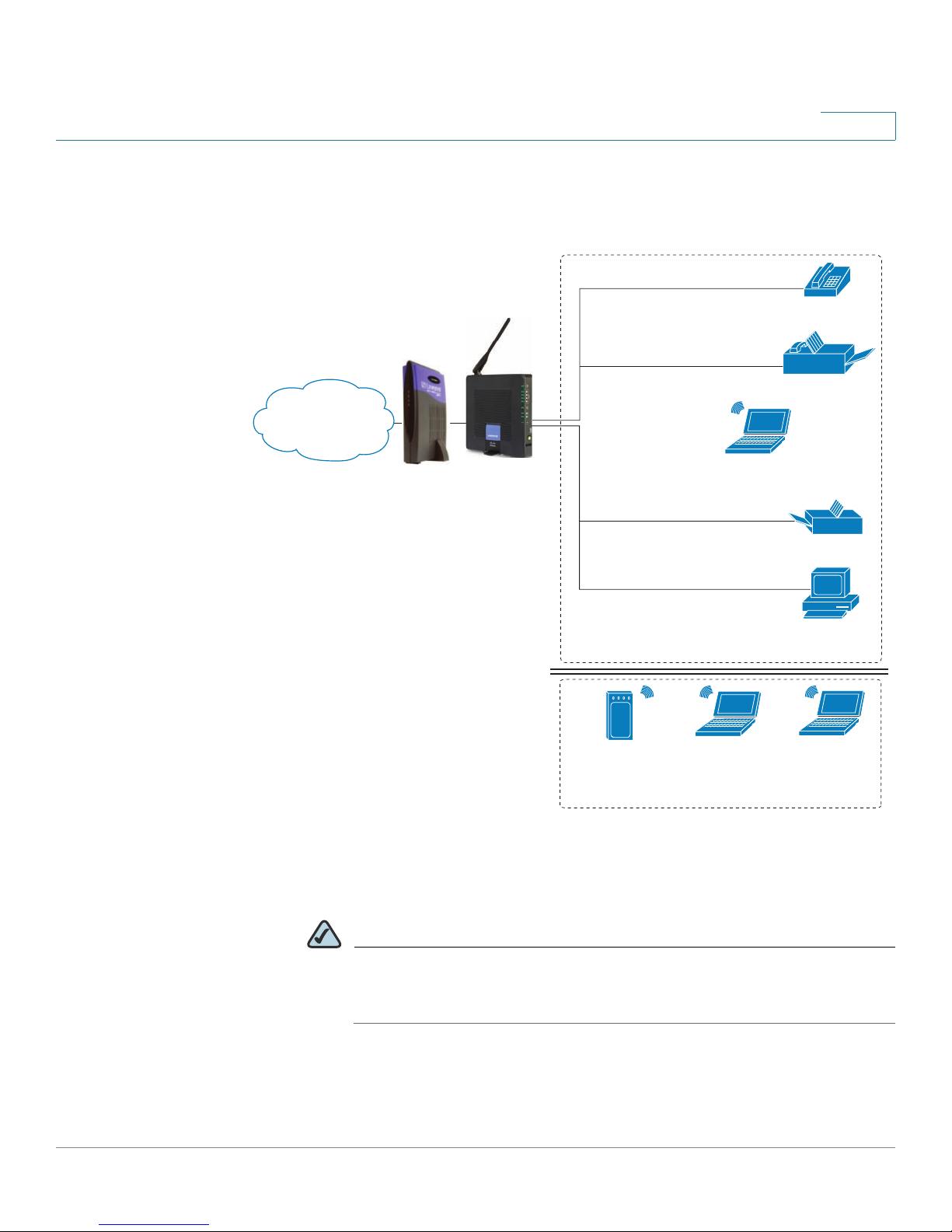
Deploying the WRP400 in a Basic Network
Internet
1
Analog phone
Fax
WRP400
Laptop
computer
Printer
Personal
computer
In this scenario, the WRP400 is deployed in a small business that has a basic
network configuration.
• The WRP400 is preconfigured by the Service Provider to act as the edge
device that routes traffic between the small business network and the
Service Provider network.
NOTE The WRP400 may be configured as an edge device or can be
connected to another device that provides access to the Service
Provider network.
• The WRP400 connects the computers to the Internet. Computers may be
connected by network cables or may operate wirelessly. All computers
have access to the printer on the local network.
• An analog phone and a fax machine are connected to the WRP400 phone
ports and have access to the configured Voice over IP services.
Cisco Small Business WRP400 Administration Guide 7
Page 10
Product Overview and Deployment Guidelines
Internet Access
Device
Wireless Guest Network
Personal
computer
WRP400
Laptop
computer
Analog phone
Fax
Printer
Private Network
Internet
194232
Deployment Models
Deploying the WRP400 with a Wireless Guest Network
1
In this example, the WRP400 is deployed in an Internet cafe.
• The WRP400 is connected to a cable modem that provides Internet access.
NOTE The WRP400 may be configured as an edge device or can be
connected to another device that provides access to the Service
Provider network.
• In the private network, a computer is connected to the WRP400 by an
Ethernet cable. The manager also has a laptop computer that can be used
wirelessly from anywhere on the premises, using the main wireless
Cisco Small Business WRP400 Administration Guide 8
Page 11

Product Overview and Deployment Guidelines
Mobile Office Network
194234
*with compatible 3G USB Modem
WRP400*
Wi-Fi Phone
Deployment Models
network, SSID1. The manager and employees using SSID1 have access to
the printer. If desired, a wireless phone also could be connected to this
network for business use.
• An analog phone and a fax machine are in the private network. The WRP400
is configured for Internet telephone service and for traditional telephone
service through a connected phone line.
• The WRP400 is configured with a guest network, SSID2, that enables the
business to provide its customers with a free wireless hotspot for their
laptop computers and other mobile devices. Because this network is
separate from the main wireless network, the customers have no access to
the manager’s computer, the printer, or the telephone service.
Deploying the WRP400 with Mobile Broadband
1
When a compatible mobile broadband modem is connected to the USB port, the
WRP400 can connect to a mobile broadband network. The mobile network can be
the primary network or can serve as a backup network to ensure continuous
Internet connectivity. Consider the two scenarios illustrated below.
Mobile Office Using the Mobile Network for Internet Access
Laptop
computer
Mobile
network
1
WRP400
Printer
Wireless Phone
In this example, a team has set up a temporary network at a construction site. The
team members have laptop computers and Wi-Fi phones that share a mobile
broadband connection for Internet access. All computers can connect to the
printer on the local network. If a Virtual Private Network (VPN) tunnel is configured
on the laptop computer, team members also can securely connect to resources at
the main office (not illustrated).
Cisco Small Business WRP400 Administration Guide 9
Page 12

Product Overview and Deployment Guidelines
Personal
computer
WRP400
Laptop
computer
Analog phone
Fax
Printer
Private Network
Internet
194233
1
Mobile
network
Failov
e
r
*with compatible 3G USB Modem
WRP400*
Deployment Models
Basic Office Deployment Using the Mobile Network as a Backup
Connection
1
In this example, the business has the same network as illustrated in Deploying the
WRP400 in a Basic Network, page 7. However, this business has the added
benefit of using the mobile broadband network as a backup network to ensure
continuous Internet connectivity. In the event that the Internet connection fails, the
WRP400 fails over to the configured mobile network. When the Internet
connection becomes available, the WRP400 recovers the connection.
Cisco Small Business WRP400 Administration Guide 10
Page 13

Product Overview and Deployment Guidelines
Local Area Network Guidelines
Local Area Network Guidelines
This section offers guidelines for setting up your Local Area Network (LAN).
NOTE As you design your network, be aware that the WRP400 is intended for deployment
in a very small business. The router is designed to handle the data, voice, and video
traffic that would be expected by office personnel who use the Internet to find data,
conduct phone conversations, transmit email, and participate in videoconferences.
For large-scale operations with heavy data, voice, and video requirements,
consider other models of Cisco Small Business routers.
Power, Cabling and Telephone Lines
1
• AC outlets: Ensure there is an AC outlet available for every network device that
requires AC power.
- The WRP400 requires power, and Ethernet switches (optional) require
power.
- Some analog telephones require AC power.
• Ethernet cabling: If an Internet access device is present, you will need to
connect it to the WRP400 with an Ethernet cable. You also will need Ethernet
cable for any devices that do not have wireless connectivity. It is
recommended that Ethernet cables are UTP Cat5e or better.
• PSTN lines: Ensure that the lines are operative and that any features, such as
caller identification, operate properly before starting the installation.
• UPS: It is strongly recommended that you included an Uninterrupted Power
Supply (UPS) mechanism in your network to ensure continuous operation
during a power failure. Connect all essential devices, including the Internet
access device, WRP400, and the Ethernet switch (if present).
Basic Services and Equipment
The following basic services and equipment are required:
• An Integrated access device or modem for broadband access to the Internet
• Business grade Internet service
Cisco Small Business WRP400 Administration Guide 11
Page 14

Product Overview and Deployment Guidelines
Special Requirements for Voice Deployments
• Internet Telephony Service Provider (ITSP) for Voice Over IP telephone service,
supporting a “bring your own device” model
• A computer with Microsoft Windows XP or Windows Vista for system
configuration
Special Requirements for Voice Deployments
Voice deployments have special requirements that you must meet to ensure voice
quality.
• “Bandwidth for Voice Deployments,” on page 12
• “NAT Mapping for Voice over IP Deployments,” on page 14
1
• “Local Area Network Design for Voice Deployments,” on page 14
Bandwidth for Voice Deployments
You can choose from several types of broadband access technologies to provide
symmetric or asymmetric connectivity to a small business. These technologies
vary on the available bandwidth and on the quality of service. For voice
deployments, it is generally recommended that you use broadband access with a
Service Level Agreement that provides quality of service. If there is not a Service
Level Agreement with regard to the broadband connection quality of service, the
downstream audio quality may be affected negatively under heavy load
conditions (bandwidth utilization beyond 80%).
To eliminate or minimize this effect, Cisco recommends one of the following
actions:
• For broadband connections with a bandwidth lower than 2 Mbps, perform the
call capacity calculations by assuming a bandwidth value of 50% of the
existing broadband bandwidth. For example, in the case of a 2 Mbps uplink
broadband connection, assume 1 Mbps. Limit the uplink bandwidth in the
Integrated Access Device to this value. This setting helps to maintain the
utilization levels below 60%, thus reducing jitter and packet loss.
• Use an additional broadband connection for voice services only. A separate
connection is required when the broadband connection services do not offer
quality of service and when it is not possible to apply the above mentioned
utilization mechanism.
Cisco Small Business WRP400 Administration Guide 12
Page 15

Product Overview and Deployment Guidelines
Special Requirements for Voice Deployments
The available connection bandwidth determines the maximum number of
simultaneous calls that the system can support with the appropriate audio quality.
Use this information to determine the maximum number of simultaneous VoIP
connections that the system can support.
For asymmetric connections, such as ADSL, the maximum number of calls is
determined by the upstream bandwidth. In general it is a good practice to use no
more than 75% of the total available bandwidth for calls. This provides space for
data traffic and helps ensure good voice quality.
NOTE Some ITSP SIP trunk services limit the maximum number of simultaneous calls.
Please check with your Service Provider to understand the maximum number of
simultaneous calls each SIP trunk supports.
The following table provides the approximate bandwidth budget for different
codecs.
1
Codec Approximate bandwidth
budget for each side of
conversation
G.711 110 kbps 220
G.726-4087 kbps 174
G.726-3279 kbps 158
G.726-2471 kbps 142
G.726-1663 kbps 126
G.729 55 kbps 110
For more information about bandwidth calculation, refer to the following web sites:
www.erlang.com/calculator/lipb/
www.bandcalc.com/
2 calls 4 calls 6 calls 8 calls
kbps
kbps
kbps
kbps
kbps
kbps
440
kbps
348
kbps
316
kbps
284
kbps
252
kbps
220
kbps
660
kbps
522
kbps
474
kbps
426
kbps
378
kbps
330
kbps
880
kbps
696
kbps
632
kbps
568
kbps
504
kbps
440
kbps
Cisco Small Business WRP400 Administration Guide 13
Page 16

Product Overview and Deployment Guidelines
Special Requirements for Voice Deployments
NAT Mapping for Voice over IP Deployments
Network Address Translation (NAT) is the function that allows multiple devices in
your small business network to share one external (public) IP address that you
receive from your Internet Service Provider. Voice over IP can co-exist with NAT
only when some form of NAT traversal is provided.
Some Internet Telephone Service Providers (ITSPs) provide NAT traversal, but
some do not. For voice deployments, it is strongly recommended that you
choose an ITSP that supports NAT mapping through a Session Border
Controller.
If your ITSP does not provide NAT mapping through a Session Border Controller
(the preferred method), you have three options for providing NAT traversal on your
WRP400:
• Deploy an edge device that has a SIP ALG (Application Layer Gateway). The
Cisco Small Business WRV200 is suited for this purpose, but other SIP-ALG
routers can be used. If your Internet Service Provider is providing the edge
device, check with your provider to determine if the router has a SIP ALG.
1
• Configure NAT mapping with the EXT IP setting. This option requires that you
have (1) a static external (public) IP address from your Internet Service Provider
and (2) an edge device with a symmetric NAT mechanism. If the WRP400 is the
edge device, the second requirement is met. For more information about the
EXT IP setting, see NAT Support Parameters section, page 70.
• Configure Simple Traversal of UDP through NAT (STUN). This option requires
that you have (1) a dynamic external (public) IP address from your service
provider, (2) a computer running STUN server software, and (3) an edge device
with an asymmetric NAT mechanism. If the WRP400 is the edge device, the
third requirement is not met. For more information about the STUN Enable
setting and the STUN Test Enable setting, see NAT Support Parameters
section, page 70.
Local Area Network Design for Voice Deployments
Use the following guidelines to manage the LAN setup for voice deployments.
• Ensure that all telephones are located in the same local area network
subnet.
• Configure your WRP400 as a DHCP server for the purpose of easily adding
network devices to the system. Ensure that the DHCP server can assign
Cisco Small Business WRP400 Administration Guide 14
Page 17

Product Overview and Deployment Guidelines
WRP400 Maintenance Operations
enough IP addresses to serve the devices that you need to connect to your
network.
• Use stable DNS server addresses for URL name resolution. Your Internet
Service Provider can provide the primary and secondary DNS server IP
addresses.
• If you need to directly connect more than four network devices (other than
wireless devices), you will need to connect an Ethernet switch to the
WRP400. For voice deployments, Cisco recommends use of the SLMxxxP,
SRWxxxP and SRWxxxMP switch product families. The SLM224P is a
popular choice. For more information about these switches, visit the
following URL: www.cisco.com/cisco/web/solutions/small_business/
products/routers_switches/index.html
• If you use an Ethernet switch, configure it to ensure voice quality. The
following settings are recommended:
1
- Enable Port Fast and Spanning Tree Protocol on the ports to which your
voice devices are connected. The Cisco phones are capable of
rebooting in a few seconds and will attempt to locate network services
while a switch port is being blocked by STP after it senses a device
reboot. Enabling Port Fast means that the network will be available to the
phones when needed. If the switch does not provide a way to enable
Port Fast, then you must disable Spanning Tree Protocol.
- In the administrative web pages for the switch, you should enable QoS
and choose DSCP as the Trust Mode.
WRP400 Maintenance Operations
Due to its unique functions, the WRP400 has unique maintenance operations as
compared to other Cisco Small Business IP telephony devices.
NOTE For complete instructions about the settings mentioned below, see the WRP400
User Guide.
• Remote Management: For security purposes, remote management is
disabled by default.
- When you first configure the WRP400, connect your administrative
Cisco Small Business WRP400 Administration Guide 15
computer directly to one of the LAN ports and enter the default static IP
Page 18

Product Overview and Deployment Guidelines
WRP400 Maintenance Operations
address into your web browser to log on to the configuration utility.
NOTE The default LAN IP address of the WRP400 is 192.168.15.1. If another
device on the network has the same IP address, the WRP400 will take
the address 192.168.16.1. You can modify the Local IP Address on the
Setup tab > Basic Setup page, Network Setup section.
If you are using the IVR, be aware that this address is NOT the address
reported by the 110 option of the IVR. The device does not respond
to the 110 option address.
- If you wish to enable web access and wireless access to the
configuration utility, you can use the Administration tab > Management
page, Web Access section.
1
• DHCP Server: The DCHP server is disabled by default. If there are no other
DHCP servers on your network, you can enable the DHCP server option to
allow your WRP400 to assign IP addresses to connected devices
automatically. This setting is on the Setup tab > Basic Setup page, DHCP
Server Setting section.
• System Logging: If you wish to enable system logging, be aware that there
are two sets of system logs: one for the data (router) functions and another
for the voice functions.
- Data (router) logging: See the Administration tab > Logging page.
- Voice logging: See the Voice tab > System page, Miscellaneous
Settings section.
• Factory Reset: If you wish to reset your WRP400 to the factory default
settings, you can reset the data (router) settings and the voice settings
separately.
Factory reset of data (router) settings: Use one of the following methods:
- Option 1: Log on to the configuration utility, and then click
Administration > Factory Defaults. Next to Restore Router Factory
Defaults, click Yes . Then click Save Settings to begin the operation.
- Option 2: Press and hold the reset button located on the side panel for
Cisco Small Business WRP400 Administration Guide 16
approximately ten seconds.
Page 19

Product Overview and Deployment Guidelines
Remote Provisioning
Factory reset of voice settings: Use one of the following methods:
- Option 1: Log on to the configuration utility, and then click
Administration tab > Factory Defaults. Next to Restore Voice Factory
Defaults, click Yes . Then click Save Settings to begin the operation.
- Option 2: Connect an analog phone to the Phone 1 or Phone 2 port.
Press **** to access the Interactive Voice Response menu. After you
hear the greeting, press 73738 for factory reset. Listen to the prompts
and then press 1 to confirm or * to cancel. After you hear “Option
successful,” you can hang up the phone.
Remote Provisioning
Like other Cisco Small Business IP Telephony Devices, the WRP400 provides for
secure provisioning and remote upgrade. Provisioning is achieved through
configuration profiles transferred to the device via TFTP, HTTP, or HTTPS. To
configure Provisioning, go to the Provisioning tab in the Configuration Utility.
1
NOTE For complete details, see the Provisioning Guide at the following URL:
www.cisco.com/en/US/docs/voice_ip_comm/csbpvga/ata/provisioning/guide/
Cisco_Small_Business_IP_Telephony_Provisioning_Guide.pdf
Upgrade URL
Remote firmware upgrade is achieved via TFTP or HTTP (firmware upgrades
using HTTPS are not supported). Remote upgrades are initiated by causing the
WRP400 to request the upgrade firmware image by providing a URL for the
WRP400 to retrieve the firmware.
NOTE If the value of the
cannot upgrade the WRP400 even if the web page indicates otherwise.
The syntax of the Upgrade URL is as follows:
http://WRP400_ip_address/admin/upgrade?[protocol://][server-
name[:port]][/firmware-pathname]
Upgrade Enable
parameter in the Provisioning page is No, you
Cisco Small Business WRP400 Administration Guide 17
Page 20

Product Overview and Deployment Guidelines
Remote Provisioning
Both HTTP and TFTP are supported for the upgrade operation.
1
protocol
If no
host that requests the URL is used as
If no port specified, the default port of the protocol is used. (69 for TFTP or 80 for
HTTP)
The
firmware-pathname
directory on the TFTP or HTTP server. If no
spa.bin
http://192.168.2.217/admin/upgrade?tftp://192.168.2.251/
spa.bin
is specified, TFTP is assumed. If no
server-name
is typically the file name of the binary located in a
firmware-pathname
is assumed, as in the following example:
server-name
.
is specified, the
is specified,
/
Resync URL
The WRP400 can be configured to automatically resync its internal configuration
state to a remote profile periodically and on power up. The automatic resyncs are
controlled by configuring the desired profile URL into the device.
The Resync URL lets you force the WRP400 to do a resync to a profile specified in
the URL, which can identify either a TFTP, HTTP, or HTTPS server. The syntax of
the Resync URL is as follows:
http://WRP400_ip_address/admin/resync?[[protocol://][server-
name[:port]]/profile-pathname]
NOTE The WRP400 resyncs only when it is idle.
If no parameter follows
page is used.
protocol
If no
host that requests the URL is used as
If no port is specified, the default port is used (69 for TFTP, 80 for HTTP, and 443
for HTTPS).
The profile-path is the path to the new profile with which to resync, for example:
http://192.168.2.217/admin/resync?tftp://192.168.2.251/
spaconf.cfg
is specified, TFTP is assumed. If no
/resync?,
the Profile Rule setting from the Provisioning
server-name
server-name
.
is specified, the
Cisco Small Business WRP400 Administration Guide 18
Page 21

Product Overview and Deployment Guidelines
Remote Provisioning
Reboot URL
The Reboot URL lets you reboot the WRP400. The Reboot URL is as follows:
http://WRP400_ip_address/admin/reboot
NOTE The WRP400 reboots only when it is idle.
Configuration Profile
Because the WRP400 has two sets of parameters, one set for data and one set for
voice, the requirements vary from the provisioning of other Cisco Small Business
IP Telephony Devices. You will have two profiles: one for the data (router)
parameters and one for the voice parameters. One benefit of having separate
profiles for voice parameters and data parameters is that you can deploy the
common data parameters to all of your customer sites and deploy the custom
voice parameters to each site individually.
1
• Data (router) parameters: Use the XML format only, as described in the
Provisioning Guide. Binary files are not supported for the configuration of
data (router) parameters. For more information about the data parameters,
see Appendix B, “Data Fields.”
• Voice parameters: Use the binary or XML format. The binary format is
generated by a profile compiler tool available from Cisco. Find the correct
SPA Profiler Compiler (SPC) for the firmware that you have installed on your
WRP400. For more information about the data parameters, see Appendix A,
“Advanced Voice Fields.”
NOTE You can download the SPC at the following URL: tools.cisco.com/
support/ downloads/go/Redirect.x?mdfid=282414113
Cisco Small Business WRP400 Administration Guide 19
Page 22

Product Overview and Deployment Guidelines
Remote Provisioning
XML Format
Use the XML format for data (router) parameters. The XML file consists of a series
of elements (one per configuration parameter), encapsulated within the element
tags <flat-profile> … </flat-profile>. The encapsulated elements specify values for
individual parameters. Here is an example of a valid XML profile:
<flat-profile>
<Admin_Passwd>some secret</Admin_Passwd>
<Upgrade_Enable>Yes</Upgrade_Enable>
</flat-profile>
The names of parameters in XML profiles can generally be inferred from the
WRP400 Configuration Utility, by substituting underscores (_) for spaces and other
control characters. To distinguish between Lines 1, 2, 3, and 4, corresponding
parameter names are augmented by the strings _1_, _2_, _3_, and _4_. For
example, Line 1 Proxy is named Proxy_1_ in XML profiles. For more information,
see Appendix C, “WRP400 Provisioning Reference.”
1
Binary Format
Binary format profiles contain voice parameter values and user access
permissions for the parameters. By convention, the profile uses the extension .cfg
(for example, spa2102.cfg). The Profile Compiler (SPC) tool compiles a plain-text
file containing parameter-value pairs into a properly formatted and encrypted .cfg
file.
The syntax of the plain-text file accepted by the profile compiler is a series of
parameter-value pairs, with the value in double quotes. Each parameter-value pair
is followed by a semicolon. Here is an example of a valid text source profile for
input to the SPC tool:
Admin_Passwd “some secret”;
Upgrade_Enable “Yes”;
The names of parameters in the source text files for the SPC tool can generally be
inferred from the WRP400 Configuration Utility, by substituting underscores (_) for
spaces and other control characters. To distinguish between Line 1, 2, 3, and 4,
corresponding parameter names are augmented by adding [1], [2], [3], or [4]. For
example, the Line 1 Proxy is named Proxy[1] in source text profiles for input to the
SPC.
Cisco Small Business WRP400 Administration Guide 20
Page 23

Configuring Your System for ITSP
Interoperability
This chapter provides configuration details to help you to ensure that your
infrastructure properly supports voice services.
• “Configuring NAT Mapping,” on page 21
• “Firewalls and SIP,” on page 26
2
• “Configuring SIP Timer Values,” on page 27
Configuring NAT Mapping
As discussed in Chapter 1, “Product Overview and Deployment Guidelines,”
some form of NAT mapping is needed to support VoIP. If your ITSP does not
support NAT mapping through a Session Border Controller, and your edge device
is not a SIP-ALG router, you can address this issue through one of the following
methods:
• “Configuring NAT Mapping with a Static IP Address,” on page 21
• “Configuring NAT Mapping with STUN,” on page 23
Configuring NAT Mapping with a Static IP Address
This option can be used if the following requirements are met:
• You must have a static external (public) IP address from your ISP.
• The edge device—that is, the router between your local area network and your
ISP network—must have a symmetric NAT mechanism. If the WRP400 is the
edge device, this requirement is met. If another device is used as the edge
device, see “Determining Whether the Router Uses Symmetric or
Asymmetric NAT,” on page 25.
Cisco Small Business WRP400 Administration Guide 21
Page 24
Configuring Your System for ITSP Interoperability
Configuring NAT Mapping
• If the WRP400 is connected to an Ethernet switch, the switch must be
configured to enable Spanning Tree Protocol and Port Fast on the port to which
the WRP400 is connected.
NOTE Use NAT mapping only if the ITSP network does not provide a Session Border
Controller functionality.
STEP 1 Start Internet Explorer, connect to the Configuration Utility, and choose Voice >
Admin Login. If prompted, enter the administrative login provided by the Service
Provider. (The default username and password are both admin.)
STEP 2 Under the Voice menu, click SIP.
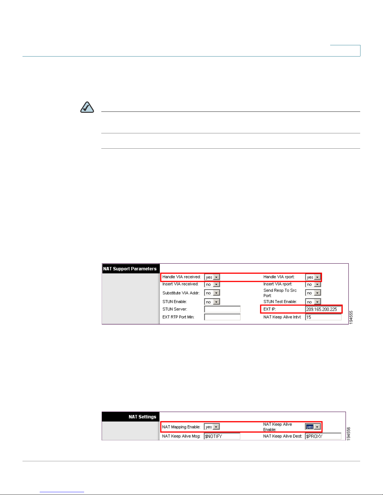
STEP 3 In the NAT Support Parameters section, enter the following settings:
2
• Handle VIA received, Insert VIA received, Substitute VIA Addr: Choose yes.
• Handle VIA rport, Insert VIA rport, Send Resp To Src Port: Choose yes.
• EXT IP: Enter the public IP address that was assigned by your ISP.
Voice tab > SIP: NAT Support Parameters
STEP 4
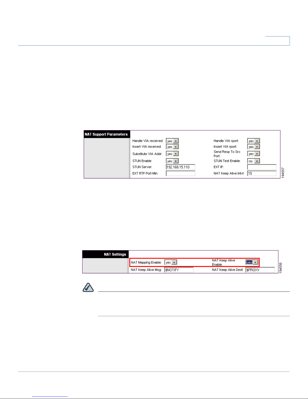
STEP 5 In the NAT Settings section, enter the following settings:
Under the Voice menu, click Line 1 or Line 2 to choose the line interface that you
want to modify.
• NAT Mapping Enable: Choose yes.
• NAT Keep Alive Enable: Choose yes.
Cisco Small Business WRP400 Administration Guide 22
Voice tab > Line N > NAT Settings
Page 25

Configuring Your System for ITSP Interoperability
Configuring NAT Mapping
STEP 6 Click Save Settings.
NOTE You also need to configure the firewall settings on your router to allow SIP
traffic. See “Firewalls and SIP,” on page 26.
Configuring NAT Mapping with STUN
This option is considered a practice of last resort and should be used only if the
other methods are unavailable. This option can be used if the following
requirements are met:
• You have a dynamically assigned external (public) IP address from your ISP.
2
• You must have a computer running STUN server software.
• The edge device uses an asymmetric NAT mechanism. If the WRP400 is the
edge device, this requirement is not met. For more information, see
“Determining Whether the Router Uses Symmetric or Asymmetric NAT,” on
page 25.
• If the WRP400 is connected to an Ethernet switch, the switch must be
configured to enable Spanning Tree Protocol and Port Fast on the port to which
the WRP400 is connected.
NOTE Use NAT mapping only if the ITSP network does not provide a Session Border
Controller functionality.
STEP 1 Start Internet Explorer, connect to the Configuration Utility, choose Voice > Admin
Login. If prompted, enter the administrative login provided by the Service
Provider. (The default username and password are both admin.)
STEP 2 Under the Voice menu, click SIP.
STEP 3 In the NAT Support Parameters section, enter the following settings:
• Handle VIA received: yes
• Handle VIA rport: yes
Cisco Small Business WRP400 Administration Guide 23
Page 26
Configuring Your System for ITSP Interoperability
Configuring NAT Mapping
• Insert VIA received: yes
• Insert VIA rport: yes
• Substitute VIA Addr: yes
• Send Resp To Src Port: yes
• STUN Enable: Choose yes.
• STUN Server: Enter the IP address for your STUN server.
Voice tab > SIP > NAT Support Parameters
2
STEP 4
STEP 5 In the NAT Settings section, enter the following settings:
Under the Voice menu, click Line 1 or Line 2 to choose the line interface that you
want to modify.
• NAT Mapping Enable: Choose yes.
• NAT Keep Alive Enable: Choose yes (optional).
Voice tab > Line N > NAT Settings
NOTE Your ITSP may require the WRP400 to send NAT keep alive messages to
keep the NAT ports open permanently. Check with your ITSP to determine
the requirements.
Cisco Small Business WRP400 Administration Guide 24
Page 27

Configuring Your System for ITSP Interoperability
Configuring NAT Mapping
STEP 6 Click Save Settings.
NOTE You also need to configure the firewall settings on your router to allow SIP
traffic. See “Firewalls and SIP,” on page 26.
Determining Whether the Router Uses Symmetric or
Asymmetric NAT
To use a STUN server, the edge device—that is, the device that routes traffic
between your private network and your ISP network—must have an asymmetric
NAT mechanism. You need to determine which type of NAT mechanism is
available on that device.
2
STUN does not work on routers with symmetric NAT. With symmetric NAT, IP
addresses are mapped from one internal IP address and port to one external,
routable destination IP address and port. If another packet is sent from the same
source IP address and port to a different destination, then a different IP address
and port number combination is used. This method is restrictive because an
external host can send a packet to a particular port on the internal host only if the
internal host first sent a packet from that port to the external host.
NOTE This procedure assumes that a syslog server is configured and is ready to receive
syslog messages.
STEP 1 Make sure you do not have firewall running on your computer that could block the
syslog port (port 514 by default).
STEP 2 Start Internet Explorer, connect to the Configuration Utility, choose Voice > Admin
Login. If prompted, enter the administrative login provided by the Service
Provider. (The default username and password are both admin.)
STEP 3 To enable debugging, complete the following tasks:
a. Under the Voice menu, click System.
b. In the Debug Server field, enter the IP address of your syslog server. This
address and port number must be reachable from the WRP400.
Cisco Small Business WRP400 Administration Guide 25
Page 28

Configuring Your System for ITSP Interoperability
Firewalls and SIP
c. From the Debug level drop-down list, choose 3.
STEP 4 To collect information about the type of NAT your router is using, complete the
following tasks:
a. Under the Voice menu, click SIP.
2
b. Scroll down to the NAT Support Parameters section.
c. From the STUN Test Enable field, choose yes.
STEP 5 To enable SIP signalling, complete the following task:
a. Under the Voice menu, click Line 1 or Line 2 to choose the line interface that
b. In the SIP Settings section, choose full from the SIP Debug Option field.
STEP 6 Click Save Settings.
STEP 7 View the syslog messages to determine whether your network uses symmetric
NAT. Look for a warning header in the REGISTER messages, such as Warning: 399
spa "Full Cone NAT Detected.”
Firewalls and SIP
To enable SIP requests and responses to be exchanged with the SIP proxy at the
ITSP, you must ensure that your firewall allows both SIP and RTP unimpeded
access to the Internet.
you want to modify.
• Make sure that the following ports are not blocked:
• SIP ports—UDP port 5060 through 5063, which are used for the ITSP line
interfaces
Cisco Small Business WRP400 Administration Guide 26
Page 29

Configuring Your System for ITSP Interoperability
Configuring SIP Timer Values
• RTP ports—16384 to 16482
• Also disable SPI (Stateful Packet Inspection) if this function exists on your
firewall.
Configuring SIP Timer Values
The default timer values should be adequate in most circumstances. However, you
can adjust the SIP timer values as needed to ensure interoperability with your
ISTP. For example, if SIP requests are returned with an “invalid certificate”
message, you may need to enter a longer SIP T1 retry value.
For more information, see ”SIP Timer Values (sec) section,” on page 65 of
Appendix A.
2
Cisco Small Business WRP400 Administration Guide 27
Page 30

Configuring Voice Services
This chapter describes how to configure your WRP400 to meet the customer’s
requirements for voice services.
• “Understanding Analog Telephone Adapter Operations,” on page 28
• “Managing Caller ID Service,” on page 37
• “Silence Suppression and Comfort Noise Generation,” on page 41
3
• “Configuring Dial Plans,” on page 42
• “Secure Call Implementation,” on page 52
Understanding Analog Telephone Adapter Operations
The WRP400 is equipped with a built-in Analog Telephone Adapter (ATA). An ATA
is an intelligent low-density Voice over IP (VoIP) gateway that enables carrierclass residential and business IP Telephony services delivered over broadband or
high-speed Internet connections. Users can access Internet phone services using
standard analog telephone equipment. In addition, the WRP400 has two line ports
that can be connected to the Public Switched Telephone Network (PSTN) so that
your business can support legacy phone numbers and fax numbers.
Cisco Small Business WRP400 Administration Guide 28
Page 31

Configuring Voice Services
T
252075
ATA S of t w ar e F ea tu r es
The WRP400 maintains the state of each call it terminates and makes the proper
reaction to user input events (such as on/off hook or hook flash). The WRP400 uses
the Session Initiation Protocol (SIP) open standard, so there is little or no
involvement by a “middle-man” server or media gateway controller. SIP allows
interoperation with all ITSPs that support SIP.
elephone/fax
V
V
WRP400
Ethernet
Internet
Access Device
Internet
Service Provider
VoIP Infrastructure
IP
SIP proxy
Voice
gateway
V
V
V
3
PSTN
Phone
ATA Software Features
The WRP400 is equipped with a full featured, fully programmable ATA that can be
custom provisioned within a wide range of configuration parameters. The
following sections describe the factors that contribute to voice quality:
• “Supported Codecs,” on page 29
• “SIP Proxy Redundancy,” on page 30
• “Other ATA Software Features,” on page 31
Supported Codecs
The WRP400 supports the following codecs:
• G.711u (configured by default) and G.711a
G.711 (A-law and mμ-law) are very low complexity codecs that support
uncompressed 64 kbps digitized voice transmissions at one through ten 5 ms
voice frames per packet. This codec provides the highest voice quality and
uses the most bandwidth of any of the available codecs.
Cisco Small Business WRP400 Administration Guide 29
Page 32

Configuring Voice Services
ATA S of t w ar e F ea tu r es
• G.726-32
• G.729a
The administrator can select the preferred codecs to be used for each line. See
“Audio Configuration section,” on page 104.
In addition, negotiation of the optimal voice codec sometimes depends on the
ability of an ATA to match a codec name with the codec used by the far-end
device. You can individually name the various codecs so that the WRP400 can
successfully negotiate the codec with the far-end equipment. For more
information, see Audio Configuration section, page 104.
3
This low complexity codec supports compressed 16, 24, 32, and 40 kbps
digitized voice transmission at one through ten 10 ms voice frames per packet.
This codec provides high voice quality.
The ITU G.729 voice coding algorithm is used to compress digitized speech.
G.729a is a reduced complexity version of G.729. It requires about half the
processing power as compared to G.729. The G.729 and G.729a bit streams
are compatible and interoperable, but not identical.
SIP Proxy Redundancy
In typical commercial IP Telephony deployments, all calls are established through
a SIP proxy server. An average SIP proxy server may handle thousands of
subscribers. It is important that a backup server be available so that an active
server can be temporarily switched out for maintenance. The WRP400 supports
the use of backup SIP proxy servers (via DNS SRV) so that service disruption
should be nearly eliminated.
A relatively simple way to support proxy redundancy is to configure your DNS
server with a list of SIP proxy addresses. The WRP400 can be instructed to
contact a SIP proxy server in a domain named in the SIP message. The WRP400
consults the DNS server to get a list of hosts in the given domain that provides SIP
services. If an entry exists, the DNS server returns an SRV record that contains a
list of SIP proxy servers for the domain, with their host names, priority, listening
ports, and so on. The WRP400 tries to contact the list of hosts in the order of their
stated priority.
If the WRP400 is currently using a lower priority proxy server, it periodically
probes the higher priority proxy to see whether it is back on line, and switches
back to the higher priority proxy when possible. SIP Proxy Redundancy is
configured in the Line and PSTN Line pages in the Configuration Utility. See
Appendix B, “Data Fields.”.
Cisco Small Business WRP400 Administration Guide 30
Page 33

Configuring Voice Services
ATA S of t w ar e F ea tu r es
Other ATA Software Features
The following table summarizes other features provided by the WRP400.
Feature Description
3
Silence
Suppression
Modem and Fax
Pass-Through
Adaptive Jitter
Buffer
See “Silence Suppression and Comfort Noise
Generation,” on page 41.
Modem pass-through mode can be triggered only by
•
predialing the number set in the
(Set in the Regional tab.)
• FAX pass-through mode is triggered by a CED/CNG tone or
an NSE event.
• Echo canceller is automatically disabled for Modem pass-
through mode.
• Echo canceller is disabled for FAX pass-through if the
parameter
for that line (in that case FAX pass-through is the same as
Modem pass-through).
• Call waiting and silence suppression is automatically
disabled for both FAX and Modem pass-through. In addition,
out-of-band DTMF Tx is disabled during modem or fax passthrough.
The WRP400 can buffer incoming voice packets to
minimize out-of-order packet arrival. This process is
known as jitter buffering. The jitter buffer size proactively
adjusts or adapts in size, depending on changing network
conditions.
FAX Disa bl e E CA N
Modem Line Toggle Code.
(Line 1 or 2 tab) is set to “yes”
International Caller
ID Delivery
Cisco Small Business WRP400 Administration Guide 31
The WRP400 has a Network Jitter Level control setting for
each line of service. The jitter level determines how
aggressively the WRP400 tries to shrink the jitter buffer
over time to achieve a lower overall delay. If the jitter level
is higher, it shrinks more gradually. If jitter level is lower, it
shrinks more quickly.
Adaptive Jitter Buffer is configured in the Line and PSTN
Line tabs. See “Advanced Voice Fields,” on page 57.
In addition to support of the Bellcore (FSK) and Swedish/
Danish (DTMF) methods of Caller ID (CID) delivery, ATAs
provide a large subset of ETSI-compliant methods to
support international CID equipment. International CID is
configured in the Line and PSTN Line tabs. See
“Advanced Voice Fields,” on page 57.
Page 34

Configuring Voice Services
ATA S of t w ar e F ea tu r es
Feature Description
Secure Calls A user (if enabled by service provider or administrator)
3
has the option to make an outbound call secure in the
sense that the audio packets in both directions are
encrypted. See “Secure Call Implementation” section
on page 52.
Adjustable Audio
Frames Per Packet
DTMF The WRP400 may relay DTMF digits as out-of-band events
Call Progress Tone
Generation
This feature allows the user to set the number of audio
frames contained in one RTP packet. Packets can be
adjusted to contain from 1–10 audio frames. Increasing the
number of packets decreases the bandwidth utilized, but
it also increases delay and may affect voice quality. See
the RTP Packet Size parameter found in the SIP tab in the
“Advanced Voice Fields,” on page 57.
to preserve the fidelity of the digits. This can enhance the
reliability of DTMF transmission required by many IVR
applications such as dial-up banking and airline
information. DTMF is configured in the
parameter found in the Line tabs. See the “Advanced
Voice Fields,” on page 57.
The WRP400 has configurable call progress tones. Call
progress tones are generated locally on the WRP400 so
an end user is advised of status (such as ringback).
Parameters for each type of tone (for instance a dial tone
played back to an end user) may include frequency and
amplitude of each component, and cadence information.
See the Regional tab in the “Advanced Voice Fields,” on
page 57.
DTMF Tx Mode
Call Progress Tone
Pass Through
Echo Cancellation Impedance mismatch between the telephone and the IP
Cisco Small Business WRP400 Administration Guide 32
This feature allows the user to hear the call progress tones
(such as ringing) that are generated from the far-end
network. See the Regional tab in the “Adv anc ed Vo ice
Fields,” on page 57.
Telephony gateway phone port can lead to near-end echo.
The WRP400 has a near-end echo canceller that
compensates for impedance match. The WRP400 also
implements an echo suppressor with comfort noise
generator (CNG) so that any residual echo is not
noticeable. Echo Cancellation is configured in the
Regional, Line, and PSTN Line tabs. See “Advanced Voice
Fields,” on page 57.
Page 35

Configuring Voice Services
ATA S of t w ar e F ea tu r es
Feature Description
3
Signaling Hook
Flash Event
Configurable Dial
Plan with Interdigit
Time rs
The WRP400 can signal hook flash events to the remote
party on a connected call. This feature can be used to
provide advanced mid-call services with third-party-callcontrol. Depending on the features that the service
provider offers using third-party-call-control, the following
ATA features may be disabled to correctly signal a hookflash event to the softswitch:
•
Call Waiting Service (parameter
Line tab)
• Three Way Conference Service (parameter
set in the Line tab)
serv
• Three Way Call Service (parameter
in the Line tab)
You can configure the length of time allowed for detection
of a hook flash using the Hook Flash Timer parameter on
the Regional tab of the Configuration Utility. See
“Advanced Voice Fields,” on page 57.
The WRP400 has three configurable interdigit timers:
Initial timeout (T)—Signals that the handset is off the hook
•
and that no digit has been pressed yet.
call waiting serv
three-way conf
three-way call serv
set in the
set
• Long timeout (L)—Signals the end of a dial string; that is, no
more digits are expected.
• Short timeout (S)—Used between digits; that is after a digit
is pressed a short timeout prevents the digit from being
recognized a second time.
See “Configuring Dial Plans,” on page 42 for more
information.
Polarity Control The WRP400 allows the polarity to be set when a call is
connected and when a call is disconnected. This feature is
required to support some pay phone system and
answering machines. Polarity Control is configured in the
Line and PSTN Line tabs. See “Advanced Voice Fields,”
on page 57.
Cisco Small Business WRP400 Administration Guide 33
Page 36

Configuring Voice Services
ATA S of t w ar e F ea tu r es
Feature Description
3
Calling Party
Control
Report Generation
and Event Logging
Syslog and Debug
Server Records
Calling Party Control (CPC) signals to the called party
equipment that the calling party has hung up during a
connected call by removing the voltage between the tip
and ring momentarily. This feature is useful for autoanswer equipment, which then knows when to disengage.
CPC is configured in the Regional, Line, and PSTN Line
tabs. See “Advanced Voice Fields,” on page 57.
The WRP400 reports a variety of status and error reports
to assist service providers to diagnose problems and
evaluate the performance of their services. The
information can be queried by an authorized agent, using
HTTP with digested authentication, for instance. The
information may be organized as an XML page or HTML
page. Report Generation and Event Logging are
configured in the System, Line, and PSTN Line tabs. See
“Advanced Voice Fields,” on page 57.
Syslog and Debug Sever Records log more details than
Report Generation and Event Logging. Using the
configuration parameters, the WRP400 allows you to
select which type of activity/events should be logged.
Syslog and Debug Server allow the information captured
to be sent to a Syslog Server. Syslog and Debug Server
Records are configured in the System, Line, and PSTN
Line tabs. See “Advanced Voice Fields,” on page 57.
SIP Over TLS The WRP400 allows the use of SIP over Transport Layer
Security (TLS). SIP over TLS is designed to eliminate the
possibility of malicious activity by encrypting the SIP
messages of the service provider and the end user. SIP
over TLS relies on the widely-deployed and standardized
TLS protocol. SIP Over TLS encrypts only the signaling
messages and not the media. A separate secure protocol
such as Secure Real-Time Transport Protocol (SRTP) can
be used to encrypt voice packets. SIP over TLS is
configured in the SIP Transport parameter configured in
the Line tab(s). See “Advanced Voice Fields,” on
page 57.
Cisco Small Business WRP400 Administration Guide 34
Page 37

Configuring Voice Services
Registering to the Service Provider
Registering to the Service Provider
To use VoIP phone service, you must configure your WRP400 to the Internet
Telephony Service Provider (ITSP).
NOTE Each line tab must be configured separately. Each line tab can be configured
for a different ITSP.
STEP 1 Start Internet Explorer, connect to the Configuration Utility, choose Voice > Admin
Login. If prompted, enter the administrative login provided by the Service
Provider. (The default username and password are both admin.)rovided by your
Service Provider.
3
STEP 2 Under the Voice menu, click Line 1 or Line 2 to choose the line interface that you
want to modify.
STEP 3 In the Proxy and Registration section, enter the Proxy.
STEP 4 In the Subscriber Information section, enter the User ID and Password.
NOTE These are the minimum settings for most ITSP connections. Enter the
account information as required by your ITSP.
STEP 5 Click Save Settings. The devices reboot.
Cisco Small Business WRP400 Administration Guide 35
Page 38

Configuring Voice Services
Registering to the Service Provider
STEP 6 To verify your progress, perform the following tasks:
• Under the Voice menu, click Info. Scroll down to the
Status section of the page, depending on which line you configured. Verify that
the line is registered. Refer to the following example.
• Use an external phone to place an inbound call to the telephone number that
was assigned by your ITSP. Assuming that you have left the default settings in
place, the phone should ring and you can pick up the phone to get two-way
audio.
• If the line is not registered, you may need to refresh the browser several times
because it can take a few seconds for the registration to succeed. Also verify
that your DNS is configured properly.
3
Line 1 Status or Line 2
Cisco Small Business WRP400 Administration Guide 36
Page 39

Configuring Voice Services
Managing Caller ID Service
Managing Caller ID Service
The choice of caller ID (CID) method is dependent on your area/region. To
configure CID, use the following parameters:
Parameter Ta b Description and Value
3
Caller ID
Method
Regional The following choices are available:
•
Bellcore (N.Amer,China)—CID, CIDCW, and VMWI.
FSK sent after first ring (same as ETSI FSK sent after
first ring) (no polarity reversal or DTAS).
• DTMF (Finland, Sweden)—CID only. DTMF sent after
polarity reversal (and no DTAS) and before first ring.
• DTMF (Denmark)—CID only. DTMF sent before first
ring with no polarity reversal and no DTAS.
• ETSI DTMF—CID only. DTMF sent after DTAS (and no
polarity reversal) and before first ring.
• ETSI DTMF With PR—CID only. DTMF sent after
polarity reversal and DTAS and before first ring.
• ETSI DTMF After Ring—CID only. DTMF sent after
first ring (no polarity reversal or DTAS).
• ETSI FSK—CID, CIDCW, and VMWI. FSK sent after
DTAS (but no polarity reversal) and before first ring.
Waits for ACK from CPE after DTAS for CIDCW.
• ETSI FSK With PR (UK)—CID, CIDCW, and VMWI.
FSK is sent after polarity reversal and DTAS and
before first ring. Waits for ACK from CPE after DTAS for
CIDCW. Polarity reversal is applied only if equipment
is on hook.
Caller ID
FSK
Standard
Cisco Small Business WRP400 Administration Guide 37
Regional
• DTMF (Denmark) With PR—CID only. DTMF sent after
polarity reversal (and no DTAS) and before first ring.
The default is Bellcore(N.Amer, China).
The WRP400 supports bell 202 and v.23 standards
for caller ID generation. Select the FSK standard you
want to use, bell 202 or v.23 .
The default is bell 202.
Page 40

Configuring Voice Services
Polarity
Reversal
First
Ring
CAS
(DTAS)
DTMF/
FSK
Polarity
Reversal
CAS
(DTAS)
FSK
CAS
(DTAS)
Wait For
ACK
FSK
First
Ring
FSK
OSI FSK
a) Bellcore/ETSI Onhook Post-Ring FSK
d) Bellcore Onhook FSK w/o Ring
f) Bellcore/ETSI Offhook FSK
c) ETSI Onhook Pre-Ring FSK/DTMF
e) ETSI Onhook FSK w/o Ring
DTMF
b) ETSI Onhook Post-Ring DTMF
First
Ring
Managing Caller ID Service
There are three types of Caller ID:
3
• On Hook Caller ID Associated with Ringing — This type of Caller ID is used
for incoming calls when the attached phone is on hook. See the following
figure (a) – (c). All CID methods can be applied for this type of CID.
• On Hook Caller ID Not Associated with Ringing — This feature is used to
send VMWI signal to the phone to turn the message waiting light on and off
(see Figure 1 (d) and (e)). This is available only for FSK-based CID methods:
(Bellcore, ETSI FSK, and ETSI FSK With PR).
• Off Hook Caller ID — This is used to delivery caller-id on incoming calls
when the attached phone is off hook (see the following figure). This can be
call waiting caller ID (CIDCW) or to notify the user that the far end party
identity has changed or updated (such as due to a call transfer). This is
available only for FSK-based CID methods: (Bellcore, ETSI FSK, and ETSI
FSK With PR).
Cisco Small Business WRP400 Administration Guide 38
Page 41

Configuring Voice Services
Optimizing Fax Completion Rates
Optimizing Fax Completion Rates
Issues can occur with fax transmissions over IP networks, even with the T.38
standard, which is supported by the WRP400. You can adjust several settings on
your WRP400 to optimize your fax completion rates.
NOTE Only T.38 Fax is supported. The WRP400 supports one connection.
STEP 1 Ensure that you have enough bandwidth for the uplink and the downlink.
• For G.711 fallback, it is recommend to have approximately 100Kbps.
• For T.38, allocate at least 50 kbps.
3
STEP 2 To optimize G.711 fallback fax completion rates, set the following on the Line tab
of your ATA device:
• Network Jitter Buffer: very high
• Jitter buffer adjustment: disable
• Call Waiting: no
• 3 Way Calling: no
• Echo Canceller: no
• Silence suppression: no
• Preferred Codec: G.711
• Use pref. codec only: yes
STEP 3 If you are using a Cisco media gateway for PSTN termination, disable T.38 (fax relay)
and enable fax using modem passthrough.
For example:
modem passthrough nse payload-type 110 codec g711ulaw
fax rate disable
fax protocol pass-through g711ulaw
STEP 4 Enable T.38 fax on the WRP400 by configuring the following parameter on the Line
tab for the FXS port to which the FAX machine is connected:
FAX_Passthru_Method: ReINVITE
Cisco Small Business WRP400 Administration Guide 39
Page 42

Configuring Voice Services
Optimizing Fax Completion Rates
NOTE If a T.38 call cannot be set-up, then the call automatically reverts to G.711
STEP 5 If you are using a Cisco media gateway use the following settings:
Make sure the Cisco gateway is correctly configured for T.38 with the SPA dial
peer. For example:
fax protocol T38
fax rate voice
fax-relay ecm disable
fax nsf 000000
no vad
3
fallback.
Fax Troubleshooting
If you have problems sending or receiving faxes, complete the following steps:
STEP 1 Verify that your fax machine is set to a speed between 7200 and 14400.
STEP 2 Send a test fax in a controlled environment between two ATAs.
STEP 3 Determine the success rate.
STEP 4 Monitor the network and record the following statistics:
• Jitter
• Loss
• Delay
STEP 5 If faxes fail consistently, capture a copy of the voice settings by selecting Save As
> Web page, complete from the administration web server page. You can send
this configuration file to Technical Support.
STEP 6 Enable and capture the debug log. For instructions, refer to Appendix D,
“Troubleshooting.”
NOTE You may also capture data using a sniffer trace.
STEP 7 Identify the type of fax machine connected to the ATA device.
Cisco Small Business WRP400 Administration Guide 40
Page 43

Configuring Voice Services
Silence Suppression and Comfort Noise Generation
STEP 8 Contact technical support:
• If you are an end user of VoIP products, contact the reseller or Internet
telephony service provider (ITSP) that supplied the equipment.
• If you are an authorized Cisco partner, contact Cisco technical support.
Silence Suppression and Comfort Noise Generation
Voice Activity Detection (VAD) with Silence Suppression is a means of increasing
the number of calls supported by the network by reducing the required bandwidth
for a single call. VAD uses a sophisticated algorithm to distinguish between
speech and non-speech signals. Based on the current and past statistics, the VAD
algorithm decides whether or not speech is present. If the VAD algorithm decides
speech is not present, the silence suppression and comfort noise generation is
activated. This is accomplished by removing and not transmitting the natural
silence that occurs in normal two-way connection. The IP bandwidth is used only
when someone is speaking. During the silent periods of a telephone call, additional
bandwidth is available for other voice calls or data traffic because the silence
packets are not being transmitted across the network.
3
Comfort Noise Generation provides artificially-generated background white noise
(sounds), designed to reassure callers that their calls are still connected during
silent periods. If Comfort Noise Generation is not used, the caller may think the call
has been disconnected because of the “dead silence” periods created by the VAD
and Silence Suppression feature.
Silence suppression is configured in the Line and PSTN Line tabs. See
Appendix B, “Data Fields.”
Cisco Small Business WRP400 Administration Guide 41
Page 44

Configuring Dial Plans
Configuring Dial Plans
Dial plans determine how the digits are interpreted and transmitted. They also
determine whether the dialed number is accepted or rejected. You can use a dial
plan to facilitate dialing or to block certain types of calls such as long distance or
international.
This section includes information that you need to understand dial plans, as well as
procedures for configuring your own dial plans. This section includes the following
topics:
• “About Dial Plans,” on page 42
• “Editing Dial Plans,” on page 50
About Dial Plans
3
This section provides information to help you understand how dial plans are
implemented.
Refer to the following topics:
• “Digit Sequences,” on page 42
• “Digit Sequence Examples,” on page 44
• “Acceptance and Transmission the Dialed Digits,” on page 47
• “Dial Plan Timer (Off-Hook Timer),” on page 48
• “Interdigit Long Timer (Incomplete Entry Timer),” on page 49
• “Interdigit Short Timer (Complete Entry Timer),” on page 49
Digit Sequences
A dial plan contains a series of digit sequences, separated by the | character. The
entire collection of sequences is enclosed within parentheses. Each digit
sequence within the dial plan consists of a series of elements, which are
individually matched to the keys that the user presses.
NOTE White space is ignored, but may be used for readability.
Cisco Small Business WRP400 Administration Guide 42
Page 45

Configuring Dial Plans
3
Digit Sequence Function
0 1 2 3 4 5 6 7 8 9 0
* #
x Enter x to represent any character on the phone
[sequence] Enter characters within square brackets to create
.
(period)
<dialed:substituted> Use this format to indicate that certain dialed
Enter any of these characters to represent a key
that the user must press on the phone keypad.
keypad.
a list of accepted key presses. The user can press
any one of the keys in the list.
Numeric range
•
For example, you would enter
user to press any one digit from 2 through 9.
• Numeric range with other characters
For example, you would enter
the user to press 3, 5, 6, 7, 8, or *.
Enter a period for element repetition. The dial plan
accepts 0 or more entries of the digit. For
example, 01. allows users to enter 0, 01, 011,
0111, and so on.
digits are replaced by other characters when the
sequence is transmitted. The dialed digits can
be zero or more characters.
[2-9] to allow the
[35-8*] to allow
Cisco Small Business WRP400 Administration Guide 43
EXAMPLE 1: <8:1650>xxxxxxx
When the user presses 8 followed by a sevendigit number, the system automatically replaces
the dialed 8 with 1650. If the user dials
85550112, the system transmits 16505550112.
EXAMPLE 2: <:1>xxxxxxxxxx
In this example, no digits are replaced. When the
user enters a 10-digit string of numbers, the
number 1 is added at the beginning of the
sequence. If the user dials 9725550112, the
system transmits 19725550112
Page 46

Configuring Dial Plans
3
Digit Sequence Function
,
(comma)
!
(exclamation point)
*xx
S0 or L0
Enter a comma between digits to play an “outside
line” dial tone after a user-entered sequence.
EXAMPLE: 9, 1xxxxxxxxxx
An “outside line” dial tone is sounded after the
user presses 9, and the tone continues until the
user presses 1.
Enter an exclamation point to prohibit a dial
sequence pattern.
EXAMPLE: 1900xxxxxxx!
The system rejects any 11-digit sequence that
begins with 1900.
Enter an asterisk to allow the user to enter a 2digit star code.
Enter S0 to reduce the short inter-digit timer to 0
seconds, or enter L0 to reduce the long inter-digit
timer to 0 seconds.
Digit Sequence Examples
The following examples show digit sequences that you can enter in a dial plan.
In a complete dial plan entry, sequences are separated by a pipe character (|), and
the entire set of sequences is enclosed within parentheses.
EXAMPLE: ( [1-8]xx | 9, xxxxxxx | 9, <:1>[2-9]xxxxxxxxx | 8,
<:1212>xxxxxxx | 9, 1 [2-9] xxxxxx xxx | 9, 1 900 xxxxxx x ! |
9, 011xxxxxx. | 0 | [49]11 )
• Extensions on your system
EXAMPLE: (
<:1212>xxxxxxx | 9, 1 [2-9] xxxxxxxxx | 9, 1 900 xxxxxxx !
| 9, 011xxxxxx. | 0 | [49]11 )
[1-8]xx Allows a user dial any three-digit number that starts with the digits 1
through 8. If your system uses four-digit extensions, you would instead enter
the following string:
[1-8]xx | 9, xxxxxxx | 9, <:1>[2-9]xxxxxxxxx | 8,
[1-8]xx x
Cisco Small Business WRP400 Administration Guide 44
Page 47

Configuring Dial Plans
3
• Local dialing with seven-digit number
EXAMPLE: ( [1-8]xx |
<:1212>xxxxxxx | 9, 1 [2-9] xxxxxxxxx | 9, 1 900 xxxxxxx !
| 9, 011xxxxxx. | 0 | [49]111)
9, xxxxxxx After a user presses 9, an external dial tone sounds. The user can
enter any seven-digit number, as in a local call.
• Local dialing with 3-digit area code and a 7-digit local number
EXAMPLE: ( [1-8]xx | 9, xxxxxxx |
<:1212>xxxxxxx | 9, 1 [2-9] xxxxxxxxx | 9, 1 900 xxxxxxx !
| 9, 011xxxxxx. | 0 | [49]11 )
9, <:1>[2-9]xxxxxxxxx This example is useful where a local area code is required.
After a user presses 9, an external dial tone sounds. The user must enter a 10digit number that begins with a digit 2 through 9. The system automatically
inserts the 1 prefix before transmitting the number to the carrier.
• Local dialing with an automatically inserted 3-digit area code
EXAMPLE: ( [1-8]xx | 9, xxxxxxx | 9, <:1>[2- 9]xxxxxxxxx |
<:1212>xxxxxxx
011xxxxxx. | 0 | [49]11 )
| 9, 1 [2-9] xxxxxxxxx | 9, 1 900 xxxxxxx ! | 9,
9, xxxxxxx | 9, <:1>[2-9]xxxxxxxxx | 8,
9, <:1>[2-9]xxxxxxxxx | 8,
8,
8, <:1212>xxxxxxx This is example is useful where a local area code is required
by the carrier but the majority of calls go to one area code. After the user
presses 8, an external dial tone sounds. The user can enter any seven-digit
number. The system automatically inserts the 1 prefix and the 212 area code
before transmitting the number to the carrier.
• U.S. long distance dialing
EXAMPLE: ( [1-8]xx | 9, xxxxxxx | 9, <:1>[2-9]xxxxxxxxx |
8, <:1212>xxxxxxx |
011xxxxxx. | 0 | [49]11 )
9, 1 [2-9] xxxxxxxxx After the user presses 9, an external dial tone sounds. The
user can enter any 11-digit number that starts with 1 and is followed by a digit
2 through 9.
9, 1 [2-9] xxxxxxxxx | 9, 1 900 xxxxx xx ! | 9,
Cisco Small Business WRP400 Administration Guide 45
Page 48

Configuring Dial Plans
• Blocked number
EXAMPLE: ( [1-8]xx | 9, xxxxxxx | 9, <:1>[2-9]xxxxxxxxx |
8, <:1212>xxxxxxx | 9, 1 [2-9] xxxxxxxxx |
9, 011xxxxxx. | 0 | [49]11 )
9, 1 900 xxxxxxx ! This digit sequence is useful if you want to prevent users from
dialing numbers that are associated with high tolls or inappropriate content,
such as 1-900 numbers in the U.S.. After the user press 9, an external dial tone
sounds. If the user enters an 11-digit number that starts with the digits 1900,
the call is rejected.
• U.S. international dialing
EXAMPLE: ( [1-8]xx | 9, xxxxxxx | 9, <:1>[2-9]xxxxxxxxx |
8, <:1212>xxxxxxx | 9, 1 [ 2-9] xxxxxxxxx | 9, 1 900 xx xxxxx
9, 011xxxxxx. | 0 | [49]11 )
! |
9, 01 1xxxxxx. After the user presses 9, an external dial tone sounds. The user can
enter any number that starts with 011, as in an international call from the U.S.
9, 1 900 xxxxxxx ! |
3
• Informational numbers
EXAMPLE: ( [1-8]xx | 9, xxxxxxx |
<:1212>xxxxxxx | 9, 1 [2-9] xxxxxxxxx | 9, 1 900 xxxxxxx !
| 9, 011xxxxxx. |
0 | [49]11 This example includes two digit sequences, separated by the pipe
character. The first sequence allows a user to dial 0 for an operator. The second
sequence allows the user to enter 411 for local information or 911 for
emergency services.
0 | [49]11 )
9, <:1>[2-9]xxxx xxxxx | 8,
Cisco Small Business WRP400 Administration Guide 46
Page 49

Configuring Dial Plans
3
Acceptance and Transmission the Dialed Digits
When a user dials a series of digits, each sequence in the dial plan is tested as a
possible match. The matching sequences form a set of candidate digit sequences.
As more digits are entered by the user, the set of candidates diminishes until only
one or none are valid. When a terminating event occurs, the WRP400 either
accepts the user-dialed sequence and initiates a call, or else rejects the sequence
as invalid. The user hears the reorder (fast busy) tone if the dialed sequence is
invalid.
The following table explains how terminating events are processed.
Ter min ati ng E ven t Processing
The dialed digits do not match
any sequence in the dial plan.
The dialed digits exactly match
one sequence in the dial plan.
A timeout occurs. The number is rejected if the dialed digits are
The user presses the # key or
the dial softkey on the phone
display.
The number is rejected.
•
If the sequence is allowed by the dial plan, the
number is accepted and is transmitted
according to the dial plan.
• If the sequence is blocked by the dial plan, the
number is rejected.
not matched to a digit sequence in the dial
plan within the time specified by the
applicable interdigit timer.
The Interdigit Long Timer applies when the
•
dialed digits do not match any digit sequence
in the dial plan. The default value is 10
seconds.
• The Interdigit Short Timer applies when the
dialed digits match one or more candidate
sequences in the dial plan. The default value is
3 seconds.
If the sequence is complete and is allowed by
•
the dial plan, the number is accepted and is
transmitted according to the dial plan.
• If the sequence is incomplete or is blocked by
the dial plan, the number is rejected.
Cisco Small Business WRP400 Administration Guide 47
Page 50

Configuring Dial Plans
3
Dial Plan Timer (Off-Hook Timer)
You can think of the Dial Plan Timer as “the off-hook timer.” This timer starts
counting when the phone goes off hook. If no digits are dialed within the specified
number of seconds, the timer expires and the null entry is evaluated. Unless you
have a special dial plan string to allow a null entry, the call is rejected. The default
value is 5.
Syntax for the Dial Plan Timer
SYNTAX: (Ps<: n> | dial plan )
• s: The number of seconds; if no number is entered after P, the default timer of 5
seconds applies.
• n: (optional): The number to transmit automatically when the timer expires; you
can enter an extension number or a DID number. No wildcard characters are
allowed because the number will be transmitted as shown. If you omit the
number substitution, <:n>, then the user hears a reorder (fast busy) tone after
the specified number of seconds.
Examples for the Dial Plan Timer
• Allow more time for users to start dialing after taking a phone off hook.
EXAMPLE: (
| 9,8,011xx. | 9,8,xx.|[1-8]xx )
P9 After taking a phone off hook, a user has 9 seconds to begin dialing. If no
digits are pressed within 9 seconds, the user hears a reorder (fast busy) tone.
By setting a longer timer, you allow more time for users to enter the digits.
• Create a hotline for all sequences on the System Dial Plan
EXAMPLE: (
9]xxxxxxxxx | 9,8,011xx. | 9,8,xx.|[1-8]xx)
P9<:23> After taking the phone off hook, a user has 9 seconds to begin dialing. If
no digits are pressed within 9 seconds, the call is transmitted automatically to
extension 23.
• Create a hotline on a line button for an extension
EXAMPLE:
P9 | (9,8<:1408>[2-9]xxxxx x | 9,8,1[2-9]xxxxxxxxx
P9<:23> | (9,8<:1408>[2-9]xxxxxx | 9,8,1[2-
( P0 <:1000>)
With the timer set to 0 seconds, the call is transmitted automatically to the
specified extension when the phone goes off hook. Enter this sequence in the
Phone Dial Plan for Ext 2 or higher on a client station.
Cisco Small Business WRP400 Administration Guide 48
Page 51

Configuring Dial Plans
NOTE This section explains how to edit a timer as part of a dial plan. Alternatively, you can
3
Interdigit Long Timer (Incomplete Entry Timer)
You can think of this timer as the “incomplete entry” timer. This timer measures the
interval between dialed digits. It applies as long as the dialed digits do not match
any digit sequences in the dial plan. Unless the user enters another digit within the
specified number of seconds, the entry is evaluated as incomplete, and the call is
rejected. The default value is 10 seconds.
modify the Control Timer that controls the default interdigit timers for all calls. See
“Resetting the Control Timers,” on page 51.
Syntax for the Interdigit Long Timer
SYNTAX: L:s, ( dial plan )
• s: The number of seconds; if no number is entered after L:, the default timer of
5 seconds applies.
• Note that the timer sequence appears to the left of the initial parenthesis for the
dial plan.
Example for the Interdigit Long Timer
EXAMPLE: L:15, (9,8<:1408>[2-9]xxxxxx | 9,8,1[2-9]xxxxxxxxx |
9,8,011xx. | 9,8,xx.|[1-8 ]xx)
L:15, This dial plan allows the user to pause for up to 15 seconds between digits
before the Interdigit Long Timer expires. This setting is especially helpful to users
such as sales people, who are reading the numbers from business cards and other
printed materials while dialing.
Interdigit Short Timer (Complete Entry Timer)
You can think of this timer as the “complete entry” timer. This timer measures the
interval between dialed digits. It applies when the dialed digits match at least one
digit sequence in the dial plan. Unless the user enters another digit within the
specified number of seconds, the entry is evaluated. If it is valid, the call proceeds.
If it is invalid, the call is rejected. The default value is 3 seconds.
Cisco Small Business WRP400 Administration Guide 49
Page 52

Configuring Dial Plans
3
Syntax for the Interdigit Short Timer
• SYNTAX 1: S:s, ( dial plan )
Use this syntax to apply the new setting to the entire dial plan within the
parentheses.
• SYNTAX 2: sequence Ss
Use this syntax to apply the new setting to a particular dialing sequence.
s: The number of seconds; if no number is entered after S, the default timer of 5
seconds applies.
Examples for the Interdigit Short Timer
• Set the timer for the entire dial plan.
EXAMPLE:
9,8,011xx. | 9,8,xx.|[1-8 ]xx)
S:6, While entering a number with the phone off hook, a user can pause for up
to 15 seconds between digits before the Interdigit Short Timer expires. This
setting is especially helpful to users such as sales people, who are reading the
numbers from business cards and other printed materials while dialing.
• Set an instant timer for a particular sequence within the dial plan.
EXAMPLE: (9,8<:1408>[2-9]xxxxxx |
9,8,011xx. | 9,8,xx.|[1-8 ]xx)
9,8,1[2-9]xxxxxxxxxS0 With the timer set to 0, the call is transmitted automatically
when the user dials the final digit in the sequence.
S:6, (9,8<:1408>[2-9]xxxx xx | 9,8,1[2-9]xxxxxxxxx |
9,8,1[2-9]xxxxxxxxxS0 |
Editing Dial Plans
You can edit dial plans and can modify the control timers.
Entering the Line Interface Dial Plan
This dial plan is used to strip steering digits from a dialed number before it is
transmitted out to the carrier.
STEP 1 Start Internet Explorer, connect to the Configuration Utility, choose Voice > Admin
Login. If prompted, enter the administrative login provided by the Service
Cisco Small Business WRP400 Administration Guide 50
Page 53

Configuring Dial Plans
STEP 2 Under the Voice menu, click Line 1 or Line 2, depending on the line interface that
STEP 3 Scroll down to the Dial Plan section.
STEP 4 Enter the digit sequences in the Dial Plan field. For more information, see “A b ou t
STEP 5 Click Save Settings.
3
Provider. (The default username and password are both admin.)rovided by your
Service Provider.
you want to configure.
Dial Plans,” on page 42.
Resetting the Control Timers
You can use the following procedure to reset the default timer settings for all calls.
NOTE If you need to edit a timer setting only for a particular digit sequence or type of call,
you can edit the dial plan. See “About Dial Plans,” on page 42.
STEP 1 Start Internet Explorer, connect to the Configuration Utility, choose Voice > Admin
Login. If prompted, enter the administrative login provided by the Service
Provider. (The default username and password are both admin.)rovided by your
Service Provider.
STEP 2 Under the Voice menu, click Regional.
STEP 3 Scroll down to the Control Timer Values section.
STEP 4 Enter the desired values in the Interdigit Long Timer field and the Interdigit Short
Timer field. Refer to the definitions at the beginning of this section.
Cisco Small Business WRP400 Administration Guide 51
Page 54

Secure Call Implementation
Secure Call Implementation
This section describes secure call implementation with the WRP400 . It includes
the following topics:
• “Enabling Secure Calls” section on page 52
• “Secure Call Details” section on page 53
• “Using a Mini-Certificate” section on page 54
• “Generating a Mini Certificate” section on page 55
3
NOTE This is an advanced topic meant for experience installers. Also see the
Guide
www.cisco.com/en/US/docs/voice_ip_comm/csbpvga/ata/provisioning/guide/
Cisco_Small_Business_IP_Telephony_Provisioning_Guide.pdf
at the following URL:
Enabling Secure Calls
A secure call is established in two stages. The first stage is no different from
normal call setup. The second stage starts after the call is established in the
normal way with both sides ready to stream RTP packets.
In the second stage, the two parties exchange information to determine if the
current call can switch over to the secure mode. The information is transported by
base64 encoding embedded in the message body of SIP INFO requests, and
responses using a proprietary format. If the second stage is successful, the
WRP400 plays a special Secure Call Indication Tone for a short time to indicate to
both parties that the call is secured and that RTP traffic in both directions is being
encrypted.
If the user has a phone that supports call waiting caller ID (CIDCW) and that
service is enabled, the CID will be updated with the information extracted from the
Mini-Certificate received from the remote party. The Name field of the CID will be
prepended with a ‘$’ symbol. Both parties can verify the name and number to
ensure the identity of the remote party.
Provisioning
Cisco Small Business WRP400 Administration Guide 52
Page 55

Secure Call Implementation
3
The signing agent is implicit and must be the same for all ATAs that communicate
securely with each other. The public key of the signing agent is pre-configured into
the WRP400 by the administrator and is used by the WRP400 to verify the MiniCertificate of its peer. The Mini-Certificate is valid if it has not expired, and it has a
valid signature.
The WRP400 can be configured so that, by default, all outbound calls are either
secure or not secure. If secure by default, the user has the option to disable
security when making a call by dialing *19 before dialing the target number. If not
secure by default, the user can make a secure outbound call by dialing *18 before
dialing the target number. However, the user cannot force inbound calls to be
secure or not secure; that depends on whether the caller has security enabled or
not.
The WRP400 will not switch to secure mode if the CID of the called party from its
Mini-Certificate does not agree with the user-id used in making the outbound call.
The WRP400 performs this check after receiving the Mini-Certificate of the called
party
Secure Call Details
Looking at the second stage of setting up a secure call in greater detail, this stage
can be further divided into two steps.
STEP 1 The caller sends a “Caller Hello” message (base64 encoded and embedded in the
message body of a SIP INFO request) to the called party with the following
information:
• Message ID (4B)
• Version and flags (4B)
• SSRC of the encrypted stream (4B)
• Mini-Certificate (252B)
Upon receiving the Caller Hello, the called party responds with a Callee Hello
message (base64 encoded and embedded in the message body of a SIP
response to the caller’s INFO request) with similar information, if the Caller Hello
message is valid. The caller then examines the Callee Hello and proceeds to the
next step if the message is valid.
Cisco Small Business WRP400 Administration Guide 53
Page 56

Secure Call Implementation
STEP 2 The caller sends the “Caller Final” message to the called party with the following
3
information:
• Message ID (4B)
• Encrypted Master Key (16B or 128b)
• Encrypted Master Salt (16B or 128b)
Using a Mini-Certificate
The Master Key and Master Salt are encrypted with the public key from the called
party mini-certificate. The Master Key and Master Salt are used by both ends for
deriving session keys to encrypt subsequent RTP packets. The called party then
responds with a Callee Final message (which is an empty message).
The Mini-Certificate (MC) contains the following information:
• User Name (32B)
• User ID or Phone Number (16B)
• Expiration Date (12B)
• Public Key (512b or 64B)
• Signature (1024b or 512B)
The MC has a 512-bit public key used for establishing secure calls. The
administrator must provision each subscriber of the secure call service with an
MC and the corresponding 512-bit private key. The MC is signed with a 1024-bit
private key of the service provider, which acts as the CA of the MC. The 1024-bit
public key of the CA signing the MC must also be provisioned for each subscriber.
The CA public key is used to verify the MC received from the other end. If the MC
is invalid, the call will not switch to secure mode. The MC and the 1024-bit CA
public key are concatenated and base64 encoded into the single parameter
Certificate
parameter, which should be kept secret, like a password. (
SRTP Private Key
. The 512-bit private key is base64 encoded into the
are configured in the Line tabs.)
SRTP Private Key
Mini Certificate
and
Mini
Because the secure call establishment relies on exchange of information
embedded in message bodies of SIP INFO requests/responses, the service
provider must ensure that the network infrastructure allows the SIP INFO
messages to pass through with the message body unmodified.
Cisco Small Business WRP400 Administration Guide 54
Page 57

Secure Call Implementation
NOTE The partner sites require a logon.
3
Generating a Mini Certificate
Cisco provides a Mini Certificate Generator for the generation of mini certificates
and private keys. Partners can download the Mini Certificate Generator by going
to Cisco Partner Central, Voice & Conferencing page, Technical Resources section.
Use the following URL:
www.cisco.com/web/partners/sell/smb/products/
voice_and_conferencing.html#~vc_technical_resources
The Mini Certificate Generator uses the following syntax:
gen_mc ca-key user-name user-id expire-date
Where:
• ca-key is a text file with the base64 encoded 1024-bit CA private/public key
pairs for signing/verifying the MC, such as the following:
9CC9aYU1X5lJuU+EBZmi3AmcqE9U1LxEOGwopaGyGOh3VyhKgi6JaVtQZt87PiJINKW8XQj3B9Qq
e3VgYxWCQNa335YCnDsenASeBxuMIEaBCYd1l1fVEodJZOGwXwfAde0MhcbD0kj7LVlzcsTyk2TZ
YTccnZ75TuTjj13qvYs=5nEtOrkCa84/mEwl3D9tSvVLyliwQ+u/
Hd+C8u5SNk7hsAUZaA9TqH8Iw0J/
IqSrsf6scsmundY5j7Z5mK5J9uBxSB8t8vamFGD0pF4zhNtbrVvIXKI9kmp4vph1C5jzO9gDfs3M
F+zjyYrVUFdM+pXtDBxmM+fGUfrpAuXb7/k=
• user-name is the name of the subscriber, such as “Joe Smith”. Maximum length
is 32 characters
• user-id is the User ID of the subscriber, which must match exactly the user-id
used in the INVITE when making the call, such as “14083331234”. The
maximum length is 16 characters.
• expire-date is the expiration date of the MC, such as “00:00:00 1/1/34”
(34=2034). Internally the date is encoded as a fixed 12B string: 000000010134
The tool generates the
be provisioned.
Mini Certificate
and
SRTP Private Key
parameters that can
Cisco Small Business WRP400 Administration Guide 55
Page 58

Secure Call Implementation
3
EXAMPLE:
gen_mc ca_key “Joe Smith” 14085551234 “00:00:00 1/1/34”
This example produces the following Mini Certificate and SRTP Private Key:
<Mini Certificate>
Sm9lIFNtaXRoAAAAAAAAAAAAAAAAAAAAAAAAAAAAAAAxNDA4NTU1MTIzNAAAAAAAMDAwMDAwMDEw
MTM00OvJakde2vVMF3Rw4pPXL7lAgIagMpbLSAG2+++YlSqt198Cp9rP/
xMGFfoPmDKGx6JFtkQ5sxLcuwgxpxpxkeXvpZKlYlpsb28L4Rhg5qZA+Gqj1hDFCmG6dffZ9SJhx
ES767G0JIS+N8lQBLr0AuemotknSjjjOy8c+1lTCd2t44Mh0vmwNg4fDck2YdmTMBR516xJt4/
uQ/
LJQlni2kwqlm7scDvll5k232EvvvVtCK0AYa4eWd6fQOpiESCO9CC9aYU1X5lJuU+EBZmi3AmcqE
9U1LxEOGwopaGyGOh3VyhKgi6JaVtQZt87PiJINKW8XQj3B9Qqe3VgYxWCQNa335YCnDsenASeBx
uMIEaBCYd1l1fVEodJZOGwXwfAde0MhcbD0kj7LVlzcsTyk2TZYTccnZ75TuTjj13qvYs=
<SRTP Private Key>
b/DWc96X4YQraCnYzl5en1CIUhVQQqrvcr6Qd/8R52IEvJjOw/
e+Klm4XiiFEPaKmU8UbooxKG36SEdKusp0AQ==
Cisco Small Business WRP400 Administration Guide 56
Page 59

Advanced Voice Fields
This appendix describes the Advanced settings that are available after you login
from the Voice > Admin Login page.
NOTE For information about the other pages in the Configuration Utility, see the WRP400
User Guide.
A
Info page
After you click the Voice tab, you can choose the following pages:
• “Info page,” on page 57
• “System page,” on page 61
• “SIP page,” on page 62
• “Regional page,” on page 72
• “Line page,” on page 92
• “User page,” on page 111
You can use the Voice tab > Info page to view information about the WRP400. This
page includes the following sections:
• “Product Information section,” on page 58
• “System Status section,” on page 58
• “Line Status section,” on page 59
NOTE The fields on the Info page are read-only and cannot be edited.
Cisco Small Business WRP400 Administration Guide 57
Page 60

Advanced Voice Fields
Info page
A
Voice tab > Info page >
Product Information section
Product Name Model number/name.
Serial Number Serial number.
Software Version Software version number.
Hardware Version Hardware version number.
MAC Address MAC address.
Client Certificate Status of the client certificate, which can indicate if the
WRP400 has been authorized by your ITSP.
Customization For a Remote Configuration (RC) unit, this field indicates
whether the unit has been customized or not. Pending
indicates a new RC unit that is ready for provisioning. If the
unit has already retrieved its customized profile, this field
displays the name of the company that provisioned the
unit.
Voice tab > Info page >
System Status section
Current Time Current date and time of the system; for example, 10/3/
2003 16:43:00.
Elapsed Time Total time elapsed since the last reboot of the system; for
example, 25 days and 18:12:36.
RTP Packets Sent Total number of RTP packets sent (including redundant
packets).
RTP Bytes Sent Total number of RTP bytes sent.
RTP Packets Recv Total number of RTP packets received (including redundant
packets).
RTP Bytes Recv Total number of RTP bytes received.
SIP Messages Sent Total number of SIP messages sent (including
retransmissions).
SIP Bytes Sent Total number of bytes of SIP messages sent (including
retransmissions).
SIP Messages
Recv
Total number of SIP messages received (including
retransmissions).
Cisco Small Business WRP400 Administration Guide 58
Page 61

Advanced Voice Fields
Info page
A
Current Time Current date and time of the system; for example, 10/3/
2003 16:43:00.
SIP Bytes Recv Total number of bytes of SIP messages received (including
retransmissions).
External IP External IP address used for NAT mapping.
Voice tab > Info page >
Line Status section
(PSTN) Hook State Hook state of the FXO port. Options are either On or Off.
Registration State Indicates if the line has registered with the SIP proxy.
Last Registration At Last date and time the line was registered.
Next Registration In Number of seconds before the next registration renewal.
Message Waiting Indicates whether you have new voice mail waiting.
Options are either Yes or No. The value automatically is set
to Yes when a message is received. You also can clear or
set the flag manually. Setting this value to Yes can activate
stutter tone and VMWI signal. This parameter is stored in
long term memory and survives after reboot or power
cycle.
Call Back Active Indicates whether a call back request is in progress.
Options are either Yes or No.
Last Called Number The last number called from the FXO Line.
Last Caller Number Number of the last caller.
Mapped SIP Port Port number of the SIP port mapped by NAT.
Call 1 and 2 State May take one of the following values:
•
Idle
• Collecting PSTN Pin
• Invalid PSTN PIN
• PSTN Caller Accepted
Call 1 and 2 Tone Type of tone used by the call.
Call 1 and 2
Encoder
Cisco Small Business WRP400 Administration Guide 59
• Connected to PSTN
Codec used for encoding.
Page 62

Advanced Voice Fields
Info page
A
Call 1 and 2
Decoder
Call 1 and 2 FAX Status of the fax pass-through mode.
Call 1 and 2 Type Direction of the call. May take one of the following values:
Call 1 and 2
Remote Hold
Call 1 and 2
Callback
Codec used for decoding.
PSTN Gateway Call = VoIP-To-PSTN Call
•
• VoIP Gateway Call = PSTN-To-VoIP Call
• PSTN To Line 1 = PSTN call ring through and answered by
Line 1
• Line 1 Forward to PSTN Gateway = VoIP calls Line 1 then
forwarded to PSTN GW
• Line 1 Forward to PSTN Number =VoIP calls Line 1 then
forwarded to PSTN number
• Line 1 To PSTN Gateway
• Line 1 Fallback To PSTN Gateway
Indicates whether the far end has placed the call on hold.
Indicates whether the call was triggered by a call back
request.
Call 1 and 2 Peer
Name
Call 1 and 2 Peer
Phone
Call 1 and 2 Call
Duration
Call 1 and 2
Packets Sent
Call 1 and 2
Packets Recv
Call 1 and 2 Bytes
Sent
Call 1 and 2 Bytes
Recv
Call 1 and 2
Decode Latency
Call 1 and 2 Jitter Number of milliseconds for receiver jitter.
Name of the internal phone.
Phone number of the internal phone.
Duration of the call.
Number of packets sent.
Number of packets received.
Number of bytes sent.
Number of bytes received.
Number of milliseconds for decoder latency.
Cisco Small Business WRP400 Administration Guide 60
Page 63

Advanced Voice Fields
System page
A
System page
Call 1 and 2 Round
Trip De lay
Call 1 and 2
Packets Lost
Call 1 and 2 Packet
Error
Call 1 and 2
Mapped RTP Port
Call 1 and 2 Media
Loopback
You can use the Voice tab > System page to configure your system and network
connections. This page includes the following sections:
• “System Configuration section” section on page 61
Number of milliseconds for delay.
Number of packets lost.
Number of invalid packets received.
The port mapped for Real Time Protocol traffic for Call 1/2.
Media loopback is used to quantitatively and qualitatively
measure the voice quality experienced by the end user.
• “Miscellaneous Settings section” section on page 62
Voice tab > System page >
System Configuration section
Restricted Access
Domains
Enable Web Admin
Access
Admin Password Password for the administrator. The default is no password.
User Password Password for the user. The default is no password.
This feature is used when implementing software
customization.
Lets you enable or disable local access to the
Configuration Utility. Select yes or no from the drop-down
menu.
The default is yes.
Cisco Small Business WRP400 Administration Guide 61
Page 64

Advanced Voice Fields
SIP page
A
Voice tab > System page >
Miscellaneous Settings section
Syslog Server Specifies the IP address of the syslog server.
Debug Server Specifies the IP address of the debug server, which logs
debug information. The level of detailed output depends on
the debug level parameter setting.
Debug Level Determines the level of debug information that is
generated. Select 0, 1, 2, or 3 from the drop-down menu.
The higher the debug level, the more debug information is
generated.
The default is 0, which indicates that no debug information
is generated.
SIP page
You can use the Voice tab > SIP page to configure the SIP settings. This page
includes the following sections:
• “SIP Parameters section” section on page 63
• “SIP Timer Values (sec) section” section on page 65
• “Response Status Code Handling section” section on page 67
• “RTP Parameters section” section on page 67
• “SDP Payload Types section” section on page 69
• “NAT Support Parameters section” section on page 70
Cisco Small Business WRP400 Administration Guide 62
Page 65

Advanced Voice Fields
SIP page
A
Voice tab > SIP page >
SIP Parameters section
Max Forward SIP Max Forward value, which can range from 1 to 255.
The default is 70.
Max Redirection Number of times an invite can be redirected to avoid an
infinite loop.
The default is 5.
Max Auth Maximum number of times (from 0 to 255) a request may
be challenged.
The default is 2.
SIP User Agent
Name
SIP Server Name Server header used in responses to inbound responses.
SIP Reg User Agent
Name
SIP Accept
Language
DTMF Relay MIME
Ty pe
Hook Flash MIME
Ty pe
User-Agent header used in outbound requests.
The default is $VERSION. If empty, the header is not
included. Macro expansion of $A to $D corresponding to
GPP_A to GPP_D allowed.
The default is $VERSION.
User-Agent name to be used in a REGISTER request. If this
value is not specified, the
is also used for the REGISTER request.
The default is blank.
Accept-Language header used. There is no default (this
indicates the WRP400 does not include this header). If
empty, the header is not included.
MIME Type used in a SIP INFO message to signal a DTMF
event.
The default is application/dtmf-relay.
MIME Type used in a SIP INFO message to signal a hook
flash event.
SIP User Agent Name
parameter
Remove Last Reg Lets you remove the last registration before registering a
Cisco Small Business WRP400 Administration Guide 63
The default is application/hook-flash.
new one if the value is different. Select yes or no from the
drop-down menu.
The default is no.
Page 66

Advanced Voice Fields
SIP page
A
Use Compact
Header
Escape Display
Name
Lets you use compact SIP headers in outbound SIP
messages. Select yes or no from the drop-down menu. If
set to yes, the WRP400 uses compact SIP headers in
outbound SIP messages. If set to no, the WRP400 uses
normal SIP headers. If inbound SIP requests contain
compact headers, the WRP400 reuses the same compact
headers when generating the response regardless the
settings of the
SIP requests contain normal headers, the WRP400
substitutes those headers with compact headers (if
defined by RFC 261) if
set to yes.
The default is no.
Lets you keep the Display Name private. Select yes if you
want the WRP400 to enclose the string (configured in the
Display Name) in a pair of double quotes for outbound SIP
messages. Any occurrences of or \ in the string is escaped
with \ and \\ inside the pair of double quotes. Otherwise,
select no.
The default is no.
Use Compact Header
Use Compact Header
parameter. If inbound
parameter is
RFC 2543 Call Hold Configures the type of call hold: a:sendonly or 0.0.0.0.
The default is no; do not use the 0.0.0.0 syntax in a HOLD
SDP; use the a:sendonly syntax.
Mark All AVT
Packets
SIP TCP Port Min Specifies the lowest TCP port number that can be used for
SIP TCP Port Max Specifies the highest TCP port number that can be used
If set to yes, all AVT tone packets (encoded for
redundancy) have the marker bit set. If set to no, only the
first packet has the marker bit set for each DTMF event.
The default is yes.
SIP sessions.
for SIP sessions.
Cisco Small Business WRP400 Administration Guide 64
Page 67

Advanced Voice Fields
SIP page
A
Voice tab > SIP page >
SIP Timer Values (sec) section
SIP T1 RFC 3261 T1 value (RTT estimate), which can range from 0
to 64 seconds.
The default is.5.
SIP T2 RFC 3261 T2 value (maximum retransmit interval for non-
INVITE requests and INVITE responses), which can range
from 0 to 64 seconds.
The default is 4.
SIP T4 RFC 3261 T4 value (maximum duration a message remains
in the network), which can range from 0 to 64 seconds.
The default is 5.
SIP Timer B INVITE time-out value, which can range from 0 to 64
seconds.
The default is 32.
SIP Timer F Non-INVITE time-out value, which can range from 0 to 64
seconds.
The default is 32.
SIP Timer H INVITE final response, time-out value, which can range from
0 to 64 seconds.
The default is 32.
SIP Timer D ACK hang-around time, which can range from 0 to 64
seconds.
The default is 32.
SIP Timer J Non-INVITE response hang-around time, which can range
from 0 to 64 seconds.
The default is 32.
INVITE Expires INVITE request Expires header value. If you enter 0, the
Expires header is not included in the request.
ReINVITE Expires ReINVITE request Expires header value. If you enter 0, the
Cisco Small Business WRP400 Administration Guide 65
31
31
–1 ) .
–1 ) .
The default is 240. Range: 0–(2
Expires header is not included in the request.
The default is 30. Range: 0–(2
Page 68

Advanced Voice Fields
SIP page
A
Reg Min Expires Minimum registration expiration time allowed from the
proxy in the Expires header or as a Contact header
parameter. If the proxy returns a value less than this setting,
the minimum value is used.
The default is 1.
Reg Max Expires Maximum registration expiration time allowed from the
proxy in the Min-Expires header. If the value is larger than
this setting, the maximum value is used.
The default is 7200.
Reg Retry Intvl Interval to wait before the WRP400 retries registration after
failing during the last registration.
The default is 30.
Reg Retry Long
Intvl
Reg Retry Random
Delay
Reg Retry Long
Random Delay
Reg Retry Intvl Cap The maximum value to cap the exponential back-off retry
When registration fails with a SIP response code that does
not match
Retry Reg RSC
of time before retrying. If this interval is 0, the WRP400
stops trying. This value should be much larger than the Reg
Retry Intvl value, which should not be 0.
The default is 1200.
Random delay range (in seconds) to add to
Intvl
when retrying REGISTER after a failure.
The default is 0, which disables this feature.
Random delay range (in seconds) to add to
Long Intvl
The default is 0, which disables this feature.
delay (which starts at
every REGISTER retry after a failure). In other words, the
retry interval is always at
a failure. If this feature is enabled,
is added on top of the exponential back-off adjusted delay
value.
, the WRP400 waits for the specified length
Register Retry
Register Retry
when retrying REGISTER after a failure.
Register Retry Intvl
Register Retry Intvl
and doubles on
seconds after
Reg Retry Random Delay
Cisco Small Business WRP400 Administration Guide 66
The default value is 0, which disables the exponential backoff feature.
Page 69

Advanced Voice Fields
SIP page
A
Voice tab > SIP page >
Response Status Code Handling section
SIT1 RSC SIP response status code for the appropriate Special
Information Tone (SIT). For example, if you set the SIT1 RSC
to 404, when the user makes a call and a failure code of
404 is returned, the SIT1 tone is played. Reorder or Busy
tone is played by default for all unsuccessful response
status code for SIT 1 RSC through SIT 4 RSC.
SIT2 RSC SIP response status code to INVITE on which to play the
SIT2 Tone.
SIT3 RSC SIP response status code to INVITE on which to play the
SIT3 Tone.
SIT4 RSC SIP response status code to INVITE on which to play the
S I T4 To n e .
Try Backup RSC SIP response code that retries a backup server for the
current request.
Retry Reg RSC Interval to wait before the WRP400 retries registration after
failing during the last registration.
The default is 30.
Voice tab > SIP page >
RTP Parameters section
RTP Port Min Minimum port number for RTP transmission and reception.
RTP Port Min
The
define a range that contains at least 4 even number ports,
such as 100 – 106.
The default is 16384.
RTP Port Max Maximum port number for RTP transmission and reception.
The default is 16482.
RTP Packet Size Packet size in seconds, which can range from 0.01 to 0.16.
Valid values must be a multiple of 0.01 seconds.
and
RTP Port Max
parameters should
Cisco Small Business WRP400 Administration Guide 67
The default is 0.030.
Page 70

Advanced Voice Fields
SIP page
A
Max RTP ICMP Err Number of successive ICMP errors allowed when
transmitting RTP packets to the peer before the WRP400
terminates the call. If value is set to 0, the WRP400 ignores
the limit on ICMP errors.
The default is 0.
RTCP Tx Interval Interval for sending out RTCP sender reports on an active
connection. It can range from 0 to 255 seconds. During an
active connection, the WRP400 can be programmed to
send out compound RTCP packet on the connection. Each
compound RTP packet except the last one contains a SR
(Sender Report) and a SDES.(Source Description). The last
RTCP packet contains an additional BYE packet. Each SR
except the last one contains exactly 1 RR (Receiver
Report); the last SR carries no RR. The SDES contains
CNAME, NAME, and TOOL identifiers. The CNAME is set to
<User ID>@<Proxy>, NAME is set to <Display Name> (or
Anonymous if user blocks caller ID), and TOOL is set to the
Vendor/Hardware-platform-software-version (such as
Cisco/wrp400-1.0.31(b)). The NTP timestamp used in the
SR is a snapshot of the WRP400’s local time, not the time
reported by an NTP server. If the WRP400 receives a RR
from the peer, it attempts to compute the round trip delay
and show it as the <Call Round Trip Delay> value (ms) in the
Info section of the WRP400 Configuration Utility.
The default is 0.
No UDP Checksum Select yes if you want the WRP400 to calculate the UDP
header checksum for SIP messages. Otherwise, select no.
The default is no.
Stats In BYE Determines whether the WRP400 includes the P-RTP-Stat
header or response to a BYE message. The header
contains the RTP statistics of the current call. Select yes or
no from the drop-down menu. The format of the P-RTP-Stat
header is:
P-RTP-State: PS=<packets sent>,OS=<octets
sent>,PR=<packets received>,OR=<octets
received>,PL=<packets lost>,JI=<jitter in ms>,LA=<delay
in ms>,DU=<call duration in
s>,EN=<encoder>,DE=<decoder>.
The default is no.
Cisco Small Business WRP400 Administration Guide 68
Page 71

Advanced Voice Fields
SIP page
A
Voice tab > SIP page >
SDP Payload Types section
NSE Dynamic
Payload
AV T D yna mi c
Payload
INFOREQ Dynamic
Payload
G726r16 Dynamic
Payload
G726r24 Dynamic
Payload
G726r32 Dynamic
Payload
G726r40 Dynamic
Payload
G729b Dynamic
Payload
NSE dynamic payload type. The valid range is 96-127.
The default is 100.
AVT dynamic payload type. The valid range is 96-127.
The default is 101.
INFOREQ dynamic payload type.
There is no default.
G.726-16 dynamic payload type. The valid range is 96-127.
The default is 98.
G.726-24 dynamic payload type. The valid range is 96-127.
The default is 97.
G726r32 dynamic payload type.
The default is 2.
G.726-40 dynamic payload type. The valid range is 96-127.
The default is 96.
G.729b dynamic payload type. The valid range is 96-127.
The default is 99.
NSE Codec Name NSE codec name used in SDP.
AV T C od ec Nam e AV T c od ec na me use d i n S DP.
G711u Codec
Name
G711a Codec
Name
G726r16 Codec
Name
Cisco Small Business WRP400 Administration Guide 69
The default is NSE.
The default is telephone-event.
G.711u codec name used in SDP.
The default is computerMU.
G.711a codec name used in SDP.
The default is computerMA.
G.726-16 codec name used in SDP.
The default is G726-16.
Page 72

Advanced Voice Fields
SIP page
A
G726r24 Codec
Name
G726r32 Codec
Name
G726r40 Codec
Name
G729a Codec
Name
G729b Codec
Name
G723 Codec Name G.723 codec name used in SDP.
EncapRTP Codec
Name
G.726-24 codec name used in SDP.
The default is G726-24.
G.726-32 codec name used in SDP.
The default is G726-32.
G.726-40 codec name used in SDP.
The default is G726-40.
G.729a codec name used in SDP.
The default is G729a.
G.729b codec name used in SDP.
The default is G729ab.
The default is G723.
EncapRTP codec name used in SDP.
The default is EncapRTP.
Voice tab > SIP page >
NAT Support Parameters section
Handle VIA
received
Handle VIA rport If you select yes, the WRP400 processes the rport
If you select yes, the WRP400 processes the received
parameter in the VIA header (this value is inserted by the
server in a response to anyone of its requests). If you select
no, the parameter is ignored. Select yes or no from the
drop-down menu.
The default is no.
parameter in the VIA header (this value is inserted by the
server in a response to anyone of its requests). If you select
no, the parameter is ignored. Select yes or no from the
drop-down menu.
The default is no.
Cisco Small Business WRP400 Administration Guide 70
Page 73

Advanced Voice Fields
SIP page
A
Insert VIA received Inserts the received parameter into the VIA header of SIP
responses if the received-from IP and VIA sent-by IP
values differ. Select yes or no from the drop-down menu.
The default is no.
Insert VIA rport Inserts the parameter into the VIA header of SIP
responses if the received-from IP and VIA sent-by IP
values differ. Select yes or no from the drop-down menu.
The default is no.
Substitute VIA Addr Lets you use NAT-mapped IP:port values in the VIA header.
Select yes or no from the drop-down menu.
The default is no.
Send Resp To Src
Port
STUN Enable Enables the use of STUN to discover NAT mapping. Select
STUN Test Enable If the STUN Enable feature is enabled and a valid STUN
STUN Server IP address or fully-qualified domain name of the STUN
Sends responses to the request source port instead of the
VIA sent-by port. Select yes or no from the drop-down
menu.
The default is no.
yes or no from the drop-down menu.
The default is no.
server is available, the WRP400 can perform a NAT-type
discovery operation when it powers on. It contacts the
configured STUN server, and the result of the discovery is
reported in a Warning header in all subsequent REGISTER
requests. If the WRP400 detects symmetric NAT or a
symmetric firewall, NAT mapping is disabled.
The default is no.
server to contact for NAT mapping discovery.
Cisco Small Business WRP400 Administration Guide 71
Page 74

Advanced Voice Fields
Regional page
A
EXT IP External IP address to substitute for the actual IP address
of the WRP400 in all outgoing SIP messages. If 0.0.0.0 is
specified, no IP address substitution is performed.
If this parameter is specified, the WRP400 assumes this IP
address when generating SIP messages and SDP (if NAT
Mapping is enabled for that line). However, the results of
STUN and VIA received parameter processing, if available,
supersede this statically configured value.
NOTE: This option requires that you have (1) a static IP
address from your Internet Service Provider and (2) an
edge device with a symmetric NAT mechanism. If the
WRP400 is the edge device, the second requirement is
met.
The default is 0.0.0.0.
Regional page
EXT RTP Port Min External port mapping number of the RTP Port Min.
number. If this value is not zero, the RTP port number in all
outgoing SIP messages is substituted for the
corresponding port value in the external RTP port range.
The default is 0.
NAT Keep Alive
Intvl
You can use the Voice tab > Regional page to localize your system with the
appropriate regional settings. This page includes the following sections:
• “Call Progress Tones section” section on page 73
• “Distinctive Ring Patterns section” section on page 75
• “Distinctive Call Waiting Tone Patterns section” section on page 76
Interval between NAT-mapping keep alive messages.
The default is 15.
• “Distinctive Ring/CWT Pattern Names section” section on page 77
• “Ring and Call Waiting Tone Spec section” section on page 78
• “Control Timer Values (sec) section” section on page 78
• “Vertical Service Activation Codes section” section on page 80
Cisco Small Business WRP400 Administration Guide 72
Page 75

Advanced Voice Fields
Regional page
A
• “Outbound Call Codec Selection Codes section” section on page 86
• “Miscellaneous section” section on page 88
Voice tab > Regional page >
Call Progress Tones section
Dial Tone Prompts the user to enter a phone number. Reorder Tone is
played automatically when
alternatives times out.
The default is 350@-19,440@-19;10(*/0/1+2).
Second Dial Tone Alternative to the Dial Tone when the user dials a three-way
call.
Dial Tone
or any of its
The default is 420@-19,520@-19;10(*/0/1+2).
Outside Dial Tone Alternative to the Dial Tone. It prompts the user to enter an
external phone number, as opposed to an internal
extension. It is triggered by a, (comma) character
encountered in the dial plan.
The default is 420@-19;10(*/0/1).
Prompt Tone Prompts the user to enter a call forwarding phone number.
The default is 520@-19,620@-19;10(*/0/1+2).
Busy Tone Played when a 486 RSC is received for an outbound call.
The default is 480@-19,620@-19;10(.5/.5/1+2).
Reorder Tone Played when an outbound call has failed or after the far end
hangs up during an established call. Reorder Tone is played
Off Hook Warning
To n e
automatically when
out.
The default is 480@-19,620@-19;10(.25/.25/1+2).
Played when the caller has not properly placed the
handset on the cradle. Off Hook Warning Tone is played
when Reorder Tone times out.
Dial Tone
or any of its alternatives times
Ring Back Tone Played during an outbound call when the far end is ringing.
Cisco Small Business WRP400 Administration Guide 73
The default is 480@10,620@0;10(.125/.125/1+2).
The default is 440@-19,480@-19;*(2/4/1+2).
Page 76

Advanced Voice Fields
Regional page
A
Ring Back 2 Tone Your WRP400 plays this ringback tone instead of
To n e
if the called party replies with a SIP 182 response
without SDP to its outbound INVITE request. The default
value is the same as
1s on and 1s off.
The default is 440@-19,480@-19;*(1/1/1+2).
Confirm Tone Brief tone to notify the user that the last input value has
been accepted.
The default is 600@-16; 1(.25/.25/1).
SIT1 Tone Alternative to the Reorder Tone played when an error
occurs as a caller makes an outbound call. The RSC to
trigger this tone is configurable on the SIP
The default is 985@-16,1428@-16,1777@-16;20(.380/0/
1,.380/0/2,.380/0/3,0/4/0).
SIT2 Tone Alternative to the Reorder Tone played when an error
occurs as a caller makes an outbound call. The RSC to
trigger this tone is configurable on the SIP
The default is 914@-16,1371@-16,1777@-16;20(.274/0/
1,.274/0/2,.380/0/3,0/4/0).
Ring Back Tone
, except the cadence is
screen.
screen.
Ring Back
SIT3 Tone Alternative to the Reorder Tone played when an error
occurs as a caller makes an outbound call. The RSC to
trigger this tone is configurable on the SIP
The default is 914@-16,1371@-16,1777@-16;20(.380/0/
1,.380/0/2,.380/0/3,0/4/0).
SIT4 Tone Alternative to the Reorder Tone played when an error
occurs as a caller makes an outbound call. The RSC to
trigger this tone is configurable on the SIP
The default is 985@-16,1371@-16,1777@-16;20(.380/0/
1,.274/0/2,.380/0/3,0/4/0).
MWI Dial Tone Played instead of the Dial Tone when there are unheard
messages in the caller’s mailbox.
The default is 350@-19,440@-19;2(.1/.1/1+2);10(*/0/
1+2).
Cfwd Dial Tone Played when all calls are forwarded.
The default is 350@-19,440@-19;2(.2/.2/1+2);10(*/0/
1+2).
screen.
screen.
Cisco Small Business WRP400 Administration Guide 74
Page 77

Advanced Voice Fields
Regional page
A
Holding Tone Informs the local caller that the far end has placed the call
on hold.
The default is 600@-19*(.1/.1/1,.1/.1/1,.1/9.5/1).
Conference Tone Played to all parties when a three-way conference call is in
progress.
The default is 350@-19;20(.1/.1/1,.1/9.7/1).
Secure Call
Indication Tone
Feature Invocation
To n e
Voice tab > Regional page >
Played when a call has been successfully switched to
secure mode. It should be played only for a short while
(less than 30 seconds) and at a reduced level (less than -19
dBm) so it does not interfere with the conversation.
The default is 397@-19,507@-19;15(0/2/0,.2/.1/1,.1/2.1/
2).
Played when a feature is implemented.
The default is 350@-16;*(.1/.1/1).
Distinctive Ring Patterns section
Ring1 Cadence Cadence script for distinctive ring 1.
The default is 60(2/4).
Ring2 Cadence Cadence script for distinctive ring 2.
The default is 60(.3/.2, 1/.2,.3/4).
Ring3 Cadence Cadence script for distinctive ring 3.
Ring4 Cadence Cadence script for distinctive ring 4.
Ring5 Cadence Cadence script for distinctive ring 5.
Ring6 Cadence Cadence script for distinctive ring 6.
Ring7 Cadence Cadence script for distinctive ring 7.
Cisco Small Business WRP400 Administration Guide 75
The default is 60(.8/.4,.8/4).
The default is 60(.4/.2,.3/.2,.8/4).
The default is 60(.2/.2,.2/.2,.2/.2,1/4).
The default is 60(.2/.4,.2/.4,.2/4).
The default is 60(.4/.2,.4/.2,.4/4).
Page 78

Advanced Voice Fields
Regional page
A
Ring8 Cadence Cadence script for distinctive ring 8.
The default is 60(0.25/9.75).
Voice tab > Regional page >
Distinctive Call Waiting Tone Patterns section
CWT1 Cadence Cadence script for distinctive CWT 1.
The default is 30(.3/9.7).
CWT2 Cadence Cadence script for distinctive CWT 2.
The default is 30(.1/.1, .1/9.7).
CWT3 Cadence Cadence script for distinctive CWT 3.
The default is 30(.1/.1, .1/.1, .1/9.3).
CWT4 Cadence Cadence script for distinctive CWT 4.
The default is 30(.1/.1, .3/ .1, .1/9.5).
CWT5 Cadence Cadence script for distinctive CWT 5.
The default is 30(.3 /.1, .1/.1, .3/ 9.1).
CWT6 Cadence Cadence script for distinctive CWT 6.
The default is 30(.3/.1,.3/.1,.1/9.1).
CWT7 Cadence Cadence script for distinctive CWT 7.
The default is 30 (.1/ .1, .3/.1, .1/9.3) .
CWT8 Cadence Cadence script for distinctive CWT 8.
The default is 2.3(.3/2).
Cisco Small Business WRP400 Administration Guide 76
Page 79

Advanced Voice Fields
Regional page
A
Voice tab > Regional page >
Distinctive Ring/CWT Pattern Names section
Ring1 Name Name in an INVITE’s Alert-Info Header to pick distinctive
ring/CWT 1 for the inbound call.
The default is Bellcore-r1.
Ring2 Name Name in an INVITE’s Alert-Info Header to pick distinctive
ring/CWT 2 for the inbound call.
The default is Bellcore-r2.
Ring3 Name Name in an INVITE’s Alert-Info Header to pick distinctive
ring/CWT 3 for the inbound call.
The default is Bellcore-r3.
Ring4 Name Name in an INVITE’s Alert-Info Header to pick distinctive
ring/CWT 4 for the inbound call.
The default is Bellcore-r4.
Ring5 Name Name in an INVITE’s Alert-Info Header to pick distinctive
ring/CWT 5 for the inbound call.
The default is Bellcore-r5.
Ring6 Name Name in an INVITE’s Alert-Info Header to pick distinctive
ring/CWT 6 for the inbound call.
The default is Bellcore-r6.
Ring7 Name Name in an INVITE’s Alert-Info Header to pick distinctive
ring/CWT 7 for the inbound call.
The default is Bellcore-r7.
Ring8 Name Name in an INVITE’s Alert-Info Header to pick distinctive
ring/CWT 8 for the inbound call.
The default is Bellcore-r8.
Cisco Small Business WRP400 Administration Guide 77
Page 80

Advanced Voice Fields
Regional page
A
Voice tab > Regional page >
Ring and Call Waiting Tone Spec section
IMPORTANT: Ring and Call Waiting tones don’t work the same way on all phones.
When setting ring tones, consider the following recommendations:
• Begin with the default Ring Waveform, Ring Frequency, and Ring Voltage.
• If your ring cadence doesn’t sound right, or your phone doesn’t ring, change
your Ring Waveform, Ring Frequency, and Ring Voltage to the following:
- Ring Waveform: Sinusoid
- Ring Frequency: 25
- Ring Voltage: 80V
Ring Waveform Waveform for the ringing signal. Choices are Sinusoid or
Trapezoid. The default is Trapezoid.
Ring Frequency Frequency of the ringing signal. Valid values are 10–100
(Hz). The default is 20.
Ring Voltage Ringing voltage. Choices are 60–90 (V). The default is 85.
CWT Frequency Frequency script of the call waiting tone. All distinctive
CWTs are based on this tone.
The default is 440@-10.
Voice tab > Regional page >
Control Timer Values (sec) section
Hook Flash Timer
Min
Hook Flash Timer
Max
Minimum on-hook time before off-hook qualifies as hookflash. Less than this the on-hook event is ignored. Range:
0.1–0.4 seconds.
The default is 0.1.
Maximum on-hook time before off-hook qualifies as hookflash. More than this the on-hook event is treated as onhook (no hook-flash event). Range: 0.4–1.6 seconds.
Cisco Small Business WRP400 Administration Guide 78
The default is 0.9.
Page 81

Advanced Voice Fields
Regional page
A
Callee On Hook
Delay
Reorder Delay Delay after far end hangs up before reorder tone is played.
Call Back Expires Expiration time in seconds of a call back activation. Range:
Call Back Retry
Intvl
Call Back Delay Delay after receiving the first SIP 18x response before
Phone must be on-hook for at this time in sec before the
WRP400 will tear down the current inbound call. It does not
apply to outbound calls. Range: 0–255 seconds.
The default is 0.
0 = plays immediately, inf = never plays. Range: 0–255
seconds.
The default is 5.
0–65535 seconds.
The default is 1800.
Call back retry interval in seconds. Range: 0–255 seconds.
The default is 30.
declaring the remote end is ringing. If a busy response is
received during this time, the WRP400 still considers the
call as failed and keeps on retrying.
The default is 0.5.
VMWI Refresh Intvl Interval between VMWI refresh to the CPE.
The default is 0.5.
Interdigit Long
Timer
Interdigit Short
Timer
Long timeout between entering digits when dialing. The
interdigit timer values are used as defaults when dialing.
The Interdigit_Long_Timer is used after any one digit, if all
valid matching sequences in the dial plan are incomplete
as dialed. Range: 0–64 seconds.
The default is 10.
Short timeout between entering digits when dialing. The
Interdigit_Short_Timer is used after any one digit, if at least
one matching sequence is complete as dialed, but more
dialed digits would match other as yet incomplete
sequences. Range: 0–64 seconds.
The default is 3.
Cisco Small Business WRP400 Administration Guide 79
Page 82

Advanced Voice Fields
Regional page
A
Ccomputer Delay Delay in seconds after caller hangs up when the WRP400
starts removing the tip-and-ring voltage to the attached
equipment of the called party. Range: 0–255 seconds. This
feature is generally used for answer supervision on the
caller side to signal to the attached equipment when the
call has been connected (remote end has answered) or
disconnected (remote end has hung up). This feature
should be disabled for the called party (in other words, by
using the same polarity for connected and idle state) and
the Ccomputer feature should be used instead.
Without Ccomputer enabled, reorder tone will is played
after a configurable delay. If Ccomputer is enabled, dial
tone will be played when tip-to-ring voltage is restored
Resolution is 1 second.
The default is 2.
Ccomputer
Duration
Voice tab > Regional page >
Duration in seconds for which the tip-to-ring voltage is
removed after the caller hangs up. After that, tip-to-ring
voltage is restored and dial tone applies if the attached
equipment is still off-hook. Ccomputer is disabled if this
value is set to 0. Range: 0 to 1.000 second. Resolution is
0.001 second.
The default is 0 (Ccomputer disabled).
Vertical Service Activation Codes section
Vertical Service Activation Codes are automatically appended to the dial-plan.
There is no need to include them in dial-plan, although no harm is done if they are
included.
Call Return Code This code calls the last caller.
The default is *69.
Call Redial Code Redials the last number called. .
Blind Transfer Code Begins a blind transfer of the current call to the extension
Cisco Small Business WRP400 Administration Guide 80
The default is *07.
specified after the activation code.
The default is *98.
Page 83

Advanced Voice Fields
Regional page
A
Call Back Act Code Starts a callback when the last outbound call is not busy.
The default is *66.
Call Back Deact
Code
Call Back Busy Act
Code
Cfwd All Act Code Forwards all calls to the extension specified after the
Cfwd All Deact
Code
Cfwd Busy Act
Code
Cfwd Busy Deact
Code
Cfwd No Ans Act
Code
Cancels a callback.
The default is *86.
Starts a callback when the last outbound call is busy.
The default is *05
activation code.
The default is *72.
Cancels call forwarding of all calls.
The default is *73.
Forwards busy calls to the extension specified after the
activation code.
The default is *90.
Cancels call forwarding of busy calls.
The default is *91.
Forwards no-answer calls to the extension specified after
the activation code.
The default is *92.
Cfwd No Ans Deact
Code
Cfwd Last Act
Code
Cfwd Last Deact
Code
Block Last Act
Code
Block Last Deact
Code
Cisco Small Business WRP400 Administration Guide 81
Cancels call forwarding of no-answer calls.
The default is *93.
Forwards the last inbound or outbound calls to the
extension specified after the activation code.
The default is *63.
Cancels call forwarding of the last inbound or outbound
calls.
The default is *83.
Blocks the last inbound call.
The default is *60.
Cancels blocking of the last inbound call.
The default is *80.
Page 84

Advanced Voice Fields
Regional page
A
Accept Last Act
Code
Accept Last Deact
Code
CW Act Code Enables call waiting on all calls.
CW Deact Code Disables call waiting on all calls.
CW Per Call Act
Code
CW Per Call Deact
Code
Block CID Act Code Blocks caller ID on all outbound calls.
Accepts the last outbound call. It lets the call ring through
when do not disturb or call forwarding of all calls are
enabled.
The default is *64.
Cancels the code to accept the last outbound call.
The default is *84.
The default is *56.
The default is *57.
Enables call waiting for the next call.
The default is *71.
Disables call waiting for the next call.
The default is *70.
The default is *67.
Block CID Deact
Code
Block CID Per Call
Act Code
Block CID Per Call
Deact Code
Block ANC Act
Code
Block ANC Deact
Code
DND Act Code Enables the do not disturb feature.
DND Deact Code Disables the do not disturb feature.
Removes caller ID blocking on all outbound calls.
The default is *68.
Blocks caller ID on the next outbound call.
The default is *81.
Removes caller ID blocking on the next inbound call.
The default is *82.
Blocks all anonymous calls.
The default is *77.
Removes blocking of all anonymous calls.
The default is *87.
The default is *78.
The default is *79.
Cisco Small Business WRP400 Administration Guide 82
Page 85

Advanced Voice Fields
Regional page
A
CID Act Code Enables caller ID generation.
The default is *65.
CID Deact Code Disables caller ID generation.
The default is *85.
CWCID Act Code Enables call waiting, caller ID generation.
The default is *25.
CWCID Deact
Code
Dist Ring Act Code Enables the distinctive ringing feature.
Dist Ring Deact
Code
Speed Dial Act
Code
Secure All Call Act
Code
Secure No Call Act
Code
Secure One Call
Act Code
Disables call waiting, caller ID generation.
The default is *45.
The default is *26
Disables the distinctive ringing feature.
The default is *46.
Assigns a speed dial number.
The default is *74.
Makes all outbound calls secure.
The default is *16.
Makes all outbound calls not secure.
The default is *17.
Makes the next outbound call secure. (It is redundant if all
outbound calls are secure by default.)
The default is *18.
Secure One Call
Deact Code
Conference Act
Code
Cisco Small Business WRP400 Administration Guide 83
Makes the next outbound call not secure. (It is redundant if
all outbound calls are not secure by default.)
The default is *19.
If this code is specified, the user must enter it before dialing
the third party for a conference call. Enter the code for a
conference call.
Page 86

Advanced Voice Fields
Regional page
A
Attn-Xfer Act Code If the code is specified, the user must enter it before dialing
the third party for a call transfer. Enter the code for a call
transfer.
Modem Line Toggle
Code
FAX Line Toggle
Code
Referral Services
Codes
Toggles the line to a modem.
The default is *99. Modem pass-through mode can be
triggered only by pre-dialing this code.
Toggles the line to a fax machine.
The default is #99.
These codes tell the WRP400 what to do when the user
places the current call on hold and is listening to the
second dial tone.
One or more *code can be configured into this parameter,
such as *98, or *97|*98|*123, etc. Max total length is 79
chars. This parameter applies when the user places the
current call on hold (by Hook Flash) and is listening to
second dial tone. Each *code (and the following valid target
number according to current dial plan) entered on the
second dial-tone triggers the WRP400 to perform a blind
transfer to a target number that is prepended by the
service *code.
For example, after the user dials *98, the WRP400 plays a
special dial tone called the Prompt Tone while waiting for
the user the enter a target number (which is checked
according to dial plan as in normal dialing). When a
complete number is entered, the WRP400 sends a blind
REFER to the holding party with the Refer-To target equals
to *98
hand off a call to an application server to perform further
processing, such as call park.
target_number
. This feature allows the WRP400 to
Cisco Small Business WRP400 Administration Guide 84
The *codes should not conflict with any of the other vertical
service codes internally processed by the WRP400. You
can empty the corresponding *code that you do not want
the WRP400 to process.
Page 87

Advanced Voice Fields
Regional page
A
Feature Dial
Services Codes
These codes tell the WRP400 what to do when the user is
listening to the first or second dial tone.
One or more *code can be configured into this parameter,
such as *72, or *72|*74|*67|*82, etc. Max total length is 79
chars. This parameter applies when the user has a dial tone
(first or second dial tone). Enter *code (and the following
target number according to current dial plan) entered at the
dial tone triggers the WRP400 to call the target number
prepended by the *code. For example, after user dials *72,
the WRP400 plays a special tone called a Prompt tone
while awaiting the user to enter a valid target number.
When a complete number is entered, the WRP400 sends a
INVITE to *72
feature allows the proxy to process features like call
forward (*72) or BLock Caller ID (*67).
The *codes should not conflict with any of the other vertical
service codes internally processed by the WRP400. You
can empty the corresponding *code that you do not want
to the WRP400 to process.
You can add a parameter to each *code in Features Dial
Services Codes to indicate what tone to play after the
*code is entered, such as *72‘c‘|*67‘p‘. Below are a list of
allowed tone parameters (note the use of back quotes
surrounding the parameter w/o spaces)
target_number
as in a normal call. This
‘c‘ = <Cfwd Dial Tone>
‘d‘ = <Dial Tone>
‘m‘ = <MWI Dial Tone>
‘o‘ = <Outside Dial Tone>
‘p‘ = <Prompt Dial Tone>
‘s‘ = <Second Dial Tone>
‘x‘ = No tones are place, x is any digit not used above
If no tone parameter is specified, the WRP400 plays
Prompt tone by default.
If the *code is not to be followed by a phone number, such
as *73 to cancel call forwarding, do not include it in this
parameter. In that case, simple add that *code in the dial
plan and the WRP400 send INVITE *73@..... as usual when
user dials *73.
Cisco Small Business WRP400 Administration Guide 85
Page 88

Advanced Voice Fields
Regional page
A
Voice tab > Regional page >
Outbound Call Codec Selection Codes section
These codes automatically appended to the dial-plan. So no need to include them
in dial-plan (although no harm to do so either).
Prefer G711u Code Makes this codec the preferred codec for the associated
call.
The default is *017110.
Force G711u Code Makes this codec the only codec that can be used for the
associated call.
The default is *027110.
Prefer G711a Code Makes this codec the preferred codec for the associated
call.
The default is *017111
Force G711a Code Makes this codec the only codec that can be used for the
associated call.
The default is *027111.
Prefer G723 Code Makes this codec the preferred codec for the associated
call.
The default is *01723.
Force G723 Code Makes this codec the only codec that can be used for the
associated call.
The default is *02723.
Prefer G726r16
Code
Force G726r16
Code
Prefer G726r24
Code
Makes this codec the preferred codec for the associated
call.
The default is *0172616.
Makes this codec the only codec that can be used for the
associated call.
The default is *0272616.
Makes this codec the preferred codec for the associated
call.
Cisco Small Business WRP400 Administration Guide 86
The default is *0172624.
Page 89

Advanced Voice Fields
Regional page
A
Force G726r24
Code
Prefer G726r32
Code
Force G726r32
Code
Prefer G726r40
Code
Force G726r40
Code
Prefer G729a Code Makes this codec the preferred codec for the associated
Makes this codec the only codec that can be used for the
associated call.
The default is *0272624.
Makes this codec the preferred codec for the associated
call.
The default is *0172632.
Makes this codec the only codec that can be used for the
associated call.
The default is *0272632.
Makes this codec the preferred codec for the associated
call.
The default is *0172640.
Makes this codec the only codec that can be used for the
associated call.
The default is *0272640.
call.
The default is *01729.
Force G729a Code Makes this codec the only codec that can be used for the
associated call.
The default is *02729.
Cisco Small Business WRP400 Administration Guide 87
Page 90

Advanced Voice Fields
Regional page
A
Voice tab > Regional page >
Miscellaneous section
Set Local Date
(mm/dd)
Set Local Time (HH/
mm)
Time Zone Selects the number of hours to add to GMT to generate the
FXS Port
Impedance
Sets the local date (mm stands for months and dd stands
for days). The year is optional and uses two or four digits.
Sets the local time (hh stands for hours and mm stands for
minutes). Seconds are optional.
local time for caller ID generation. Choices are GMT-12:00,
GMT-11:00,…, GMT, GMT+01:00, GMT+02:00, …,
GMT+13:00.
The default is GMT-08:00.
Sets the electrical impedance of the FXS port. Choices are
600, 900, 600+2.16uF, 900+2.16uF, 270+750||150nF,
220+850||120nF, 220+820||115nF, or 200+600||100nF.
The default is 600.
Cisco Small Business WRP400 Administration Guide 88
Page 91

Advanced Voice Fields
Regional page
A
Daylight Saving
Time Rule
Enter the rule for calculating daylight saving time; it should
include the start, end, and save values. This rule is
comprised of three fields. Each field is separated by ; (a
semicolon) as shown below. Optional values inside [ ] (the
brackets) are assumed to be 0 if they are not specified.
Midnight is represented by 0:0:0 of the given date.
SYNTAX: Start = <start-time>; end=<end-time>; save =
<save-time>.
The <start-time> and <end-time> values specify the start
and end dates and times of daylight saving time. Each value
is in this format: <month> /<day> / <weekday>[/
HH:[mm[:ss]]]
The <save-time> value is the number of hours, minutes,
and/or seconds to add to the current time during daylight
saving time. The <save-time> value can be preceded by a
negative (-) sign if subtraction is desired instead of addition.
The <save-time> value is in this format: [/[+|-]HH:[mm[:ss]]]
The <month> value equals any value in the range 1-12
(January-December).
The <day> value equals [+|-] any value in the range 1-31.
If <day> is 1, it means the <weekday> on or before the end
of the month (in other words the last occurrence of <
weekday> in that month).
The <weekday> value equals any value in the range 1-7
(Monday-Sunday). It can also equal 0. If the <weekday>
value is 0, this means that the date to start or end daylight
saving is exactly the date given. In that case, the <day>
value must not be negative. If the <weekday> value is not 0
and the <day> value is positive, then daylight saving starts
or ends on the <weekday> value on or after the date given.
If the <weekday> value is not 0 and the <day> value is
negative, then daylight saving starts or ends on the
<weekday> value on or before the date given.
The abbreviation HH stands for hours (0-23).
The abbreviation mm stands for minutes (0-59).
The abbreviation ss stands for seconds (0-59).
The default Daylight Saving Time Rule is start=4/1/
7;end=10/-1/7;save=1.
Cisco Small Business WRP400 Administration Guide 89
Page 92

Advanced Voice Fields
Regional page
A
Daylight Saving
Time Enab le
FXS Port Input Gain Input gain in dB, up to three decimal places. The range is
FXS Port Output
Gain
DTMF Playback
Level
DTMF Playback
Length
Detect ABCD To enable local detection of DTMF ABCD, select yes.
Daylight Saving Time can be turned on or off. This option
affects the time stamp on CallerID and affects all the lines
and extensions of the phone. Default is Yes (on).
6.000 to -12.000.
The default is -3.
Output gain in dB, up to three decimal places. The range is
6.000 to -12.000. The Call Progress Tones and DTMF
playback level are not affected by the
parameter.
Gain
The default is -3.
Local DTMF playback level in dBm, up to one decimal
place.
The default is -16.0.
Local DTMF playback duration in milliseconds.
The default is .1.
Otherwise, select no.
FXS Port Output
The default is yes. Setting has no effect if DTMF Tx Method
is INFO; ABCD is always sent OOB regardless in this
setting.
Playback ABCD To enable local playback of OOB DTMF ABCD, select yes.
Otherwise, select no.
The default is yes.
Cisco Small Business WRP400 Administration Guide 90
Page 93

Advanced Voice Fields
Regional page
Caller ID Method The following choices are available:
Bellcore (N.Amer,China)—CID, CIDCW, and VMWI. FSK sent
•
after first ring (same as ETSI FSK sent after first ring) (no
polarity reversal or DTAS).
• DTMF (Finland, Sweden)—CID only. DTMF sent after polarity
reversal (and no DTAS) and before first ring.
• DTMF (Denmark)—CID only. DTMF sentbefore first ring with
no polarity reversal and no DTAS.
• ETSI DTMF—CID only. DTMF sent after DTAS (and no polarity
reversal) and before first ring.
• ETSI DTMF With PR—CID only. DTMF sent after polarity
reversal and DTAS and before first ring.
• ETSI DTMF After Ring—CID only. DTMF sent after first ring
(no polarity reversal or DTAS).
A
Caller ID FSK
Standard
Feature Invocation
Method
More Echo
Suppression
• ETSI FSK—CID, CIDCW, and VMWI. FSK sent after DTAS (but
no polarity reversal) and before first ring. Waits for ACK from
CPE after DTAS for CIDCW.
• ETSI FSK With PR (UK)—CID, CIDCW, and VMWI. FSK is
sent after polarity reversal and DTAS and before first ring.
Waits for ACK from CPE after DTAS for CIDCW. Polarity
reversal is applied only if equipment is on hook.
• DTMF (Denmark) With PR—CID only. DTMF sent after
polarity reversal (and no DTAS) and before first ring.
The default is Bellcore(N.Amer, China).
The WRP400 supports bell 202 and v.23 standards for
caller ID generation. Select the FSK standard you want to
use, bell 202 or v.2 3.
The default is bell 202.
Select the method you want to use, Default or Sweden
default. The default is Default.
Enable or disable more echo suppresion. The default is no.
Cisco Small Business WRP400 Administration Guide 91
Page 94

Advanced Voice Fields
Line page
Line page
A
You can use the Voice tab > Line page to configure the lines for voice service. This
page includes the following sections:
• “Line Enable section” section on page 92
• “Streaming Audio Server (SAS) section” section on page 93
• “NAT Settings section” section on page 94
• “Network Settings section” section on page 94
• “SIP Settings section” section on page 95
• “Call Feature Settings section” section on page 98
• “Proxy and Registration section” section on page 99
• “Subscriber Information section” section on page 101
• “Supplementary Service Subscription section” section on page 102
• “Audio Configuration section” section on page 104
• “Dial Plan section” section on page109
• “FXS Port Polarity Configuration section” section on page 110
In a configuration profile, the Line parameters must be appended with the
appropriate numeral (for example, [1] or [2]) to identify the line to which the setting
applies.
Voice tab > Line page >
Line Enable section
Line Enable
To enable this line for service, select yes. Otherwise, select
no.
The default is yes.
Cisco Small Business WRP400 Administration Guide 92
Page 95

Advanced Voice Fields
Line page
A
Voice tab > Line page >
Streaming Audio Server (SAS) section
SAS Enable
SAS DLG Refresh
Intvl
SAS Inbound RTP
Sink
To enable the use of the line as a streaming audio source,
select yes. Otherwise, select no. If enabled, the line cannot
be used for outgoing calls. Instead, it auto-answers
incoming calls and streams audio RTP packets to the caller.
The default is no.
If this value is not zero, it is the interval at which the
streaming audio server sends out session refresh (SIP reINVITE) messages to determine whether the connection to
the caller is still active. If the caller does not respond to the
refresh message, the WRP400 ends this call with a SIP BYE
message. The range is 0 to 255 seconds (0 means that the
session refresh is disabled).
The default is 30.
This setting works around devices that do not play inbound
RTP if the streaming audio server line declares itself as a
send-only device and tells the client not to stream out
audio. Enter a Fully Qualified Domain Name (FQDN) or IP
address of an RTP sink; this value is used by the streaming
audio server line in the SDP of its 200 response to an
inbound INVITE message from a client.
The purpose of this parameter is to work around devices
that do not play inbound RTP if the SAS line declares itself
as a send-only device and tells the client not to stream out
audio. This parameter is a FQDN or IP address of a RTP
sink to be used by the SAS line in the SDP of its 200
response to inbound INVITE from a client. It will appear in
the c = line and the port number and, if specified, in the m =
line of the SDP. If this value is not specified or equal to 0,
then c = 0.0.0.0 and a=sendonly will be used in the SDP to
tell the SAS client to not to send any RTP to this SAS line. If
a non-zero value is specified, then a=sendrecv and the
SAS client will stream audio to the given address. Special
case: If the value is $IP, then the SAS line’s own IP address
is used in the c = line and a=sendrecv. In that case the SAS
client will stream RTP packets to the SAS line.
The default value is empty.
Cisco Small Business WRP400 Administration Guide 93
Page 96

Advanced Voice Fields
Line page
A
Voice tab > Line page >
NAT Settings section
NAT Mapping
Enable
NAT Keep Alive
Enable
NAT Keep Alive
Msg
NAT Keep Alive
Dest
Voice tab > Line page >
To use externally mapped IP addresses and SIP/RTP ports
in SIP messages, select yes. Otherwise, select no.
The default is no.
To send the configured NAT keep alive message
periodically, select yes. Otherwise, select no.
The default is no.
Enter the keep alive message that should be sent
periodically to maintain the current NAT mapping. If the
value is $NOTIFY, a NOTIFY message is sent. If the value is
$REGISTER, a REGISTER message without contact is sent.
The default is $NOTIFY.
Destination that should receive NAT keep alive messages.
If the value is $PROXY, the messages are sent to the
current proxy server or outbound proxy server.
The default is $PROXY.
Network Settings section
SIP ToS/DiffServ
Value
SIP CoS Value [0-7]
RTP ToS/DiffServ
Value
RTP CoS Value [07]
Cisco Small Business WRP400 Administration Guide 94
TOS/DiffServ field value in UDP IP packets carrying a SIP
message.
The default is 0x68.
CoS value for SIP messages.
The default is 3.
ToS/DiffServ field value in UDP IP packets carrying RTP
data.
The default is 0xb8.
CoS value for RTP data.
The default is 6.
Page 97

Advanced Voice Fields
Line page
A
Network Jitter
Level
Jitter Buffer
Adjustment
Voice tab > Line page >
Determines how jitter buffer size is adjusted by the
WRP400. Jitter buffer size is adjusted dynamically. The
minimum jitter buffer size is 30 milliseconds or (10
milliseconds + current RTP frame size), whichever is larger,
for all jitter level settings. However, the starting jitter buffer
size value is larger for higher jitter levels. This setting
controls the rate at which the jitter buffer size is adjusted to
reach the minimum. Select the appropriate setting: low,
medium, high, very high, or extremely high.
The default is high.
Controls how the jitter buffer should be adjusted. Select
the appropriate setting: up and down, up only, down only,
or disable.
The default is up and down.
SIP Settings section
Field Description
SIP Transport
SIP Port
SIP 100REL Enable
EXT SIP Port The external SIP port number.
The TCP choice provides “guaranteed delivery”, which
assures that lost packets are retransmitted. TCP also
guarantees that the SIP packages are received in the same
order that they were sent. As a result, TCP overcomes the
main disadvantages of UDP. In addition, for security
reasons, most corporate firewalls block UDP ports. With
TCP, new ports do not need to be opened or packets
dropped, because TCP is already in use for basic activities
such as Internet browsing or e-commerce. Options are:
UDP, TCP, TLS. The default is UDP.
Port number of the SIP message listening and transmission
port.
The default is 5060.
To enable the support of 100REL SIP extension for reliable
transmission of provisional responses (18x) and use of
PRACK requests, select yes. Otherwise, select no.
The default is no.
Cisco Small Business WRP400 Administration Guide 95
Page 98

Advanced Voice Fields
Line page
A
Auth ResyncReboot
SIP Proxy-Require
SIP Remote-PartyID
SIP GUID
If this feature is enabled, the WRP400 authenticates the
sender when it receives the NOTIFY resync reboot (RFC
2617) message. To use this feature, select yes. Otherwise,
select no.
The default is yes.
The SIP proxy can support a specific extension or behavior
when it sees this header from the user agent. If this field is
configured and the proxy does not support it, it responds
with the message, unsupported. Enter the appropriate
header in the field provided.
To use the Remote-Party-ID header instead of the From
header, select yes. Otherwise, select no.
The default is yes.
The Global Unique ID is generated for each line for each
device. When it is enabled, the WRP400 adds a GUID
header in the SIP request. The GUID is generated the first
time the unit boots up and stays with the unit through
rebooting and even factory reset. This feature was
requested by Bell Canada (Nortel) to limit the registration of
SIP accounts.
The default is yes.
Cisco Small Business WRP400 Administration Guide 96
Page 99

Advanced Voice Fields
Line page
A
SIP Debug Option SIP messages are received at or sent from the proxy listen
port. This feature controls which SIP messages to log.
Choices are as follows:
none—No logging.
•
• 1-line—Logs the start-line only for all messages.
• 1-line excl. OPT—Logs the start-line only for all messages
except OPTIONS requests/responses.
• 1-line excl. NTFY—Logs the start-line only for all messages
except NOTIFY requests/responses.
• 1-line excl. REG—Logs the start-line only for all messages
except REGISTER requests/responses.
• 1-line excl. OPT|NTFY|REG—Logs the start-line only for all
messages except OPTIONS, NOTIFY, and REGISTER
requests/responses.
• full—Logs all SIP messages in full text.
• full excl. OPT—Logs all SIP messages in full text except
OPTIONS requests/responses.
• full excl. NTFY—Logs all SIP messages in full text except
NOTIFY requests/responses.
• full excl. REG—Logs all SIP messages in full text except
REGISTER requests/responses.
• full excl. OPT|NTFY|REG—Logs all SIP messages in full text
except for OPTIONS, NOTIFY, and REGISTER requests/
responses.
• The default is none.
RTP Log Intvl The interval for the RTP log.
Restrict Source IP
If Lines 1 and 2 use the same SIP Port value and the
Restrict Source IP feature is enabled, the proxy IP address
for Lines 1 and 2 is treated as an acceptable IP address for
both lines. To enable the Restrict Source IP feature, select
yes. Otherwise, select no. If configured, the WRP400 will
drop all packets sent to its SIP Ports originated from an
untrusted IP address. A source IP address is untrusted if it
does not match any of the IP addresses resolved from the
configured
Proxy
Proxy
is yes).
(or
Outbound Proxy
if
Use Outbound
Cisco Small Business WRP400 Administration Guide 97
The default is no.
Page 100

Advanced Voice Fields
Line page
A
Referor Bye Delay
Refer Target Bye
Delay
Referee Bye Delay
R e fe r -To Tar ge t
Contact
Sticky 183
Controls when the WRP400 sends BYE to terminate stale
call legs upon completion of call transfers. Multiple delay
settings (Referor, Refer Target, Referee, and Refer-To
Target) are configured on this screen. For the Referor Bye
Delay, enter the appropriate period of time in seconds.
The default is 4.
For the Refer Target Bye Delay, enter the appropriate
period of time in seconds.
The default is 0.
For the Referee Bye Delay, enter the appropriate period of
time in seconds.
The default is 0.
To contact the refer-to target, select yes. Otherwise, select
no.
The default is no.
If this feature is enabled, the IP telephony ignores further
180 SIP responses after receiving the first 183 SIP
response for an outbound INVITE. To enable this feature,
select yes. Otherwise, select no.
The default is no.
Auth INVITE
Voice tab > Line page >
When enabled, authorization is required for initial incoming
INVITE requests from the SIP proxy.
Call Feature Settings section
Blind Attn-Xfer
Enable
Enables the WRP400 to perform an attended transfer
operation by ending the current call leg and performing a
blind transfer of the other call leg. If this feature is disabled,
the WRP400 performs an attended transfer operation by
referring the other call leg to the current call leg while
maintaining both call legs. To use this feature, select yes.
Otherwise, select no.
The default is no.
Cisco Small Business WRP400 Administration Guide 98
 Loading...